

Page 1

ARENA 30 C
WALL-HUNG, PRE-MIX
GAS-FIRED CONDENSING BOILER
INSTALLATION
AND
OPERATING INSTRUCTIONS
Appr. nr. B99.14 A - CE 0063 BL 3475
cod. 3543643/1 ediz. 04/2002
Page 2

ARENA 30 C
2
IMPORTANT
Your “benchmark” Installation, Commissioning and Service Record Log Book will be enclosed in
your customer information pack.
“This record must be completed and left with the end user”.
Ferroli is a member of the Benchmark initiative and fully supports the aims of the programme.
Benchmark has been introduced to improve the standards of installation and commissioning of central
heating systems in the UK and to encourage the regular servicing of all central heating systems to
ensure safety and efficiency.
Please see installation and servicing guidelines.
CE MARK
CE mark documents that the Ferroli gas appliances comply with the requirement contained in
European directives applicable to them.
In particular, the appliances comply with the following CEE directives and the technical specifications
provided from them:
• Gas appliances directive 90/396
• Efficiencies directive 92/42
• Low tension directive 73/23 (modified from the 93/68)
• Electromagnetic compatibility directive 89/396 (modified from the 93/68)
Year 2000 Compliance Declaration
We will guarantee that this products is altogether suitable for the data change in the Year 2000 (boiler
has no dependence from date change) and that no disruptions will occur which is caused by this
product.
• Read the warnings given in this manual thoroughly. They provide important information for safe
installation, use and maintenance
• Keep the manual carefully for future consultation.
• The instruction manual is an integral and essential
part of the product and must be kept by the user.
• If the appliance is sold or transferred to another
owner or if the owner moves, leaving the appliance behind, always ensure that the manual is
kept with the appliance for consultation by the
new owner and /or installer.
• Incorrect installation or poor maintenance absolves the manufacturer from all liability for damage to people or things.
• Installation and maintenance must be carried out
i conformity with current legislation, according to
the manufacturer’s instructions and by qualified
personnel.
• Before cleaning or maintenance, disconnect the
appliance from the mains via the switch on the
appliance or a suitable isolating device.
• In the event of malfunction or faulty operation,
deactivate the appliance. Do not attempt to repair or carry out any other operation on the
appliance directly. Contact qualified personnel
only.
• Repairs or the replacement of components must
be carried out exclusively by qualified personnel
using original spare parts only. Failure to respect
the above my compromise the safety of the appliance.
• To guarantee efficient operation, the appliance
must be serviced once a year by an authorised
service centre.
• The appliance may not be used for purposes
other than those for which it was explicitly designed. Any other use is considered improper and
therefore dangerous.
• Incorrect installation and use or failure to follow
the instructions provided by the manufacturer
absolve the manufacturer from all liability for
damage.
• After unpacking, check that the contents are
whole and undamaged.
• Keep packing out of reach of children as it is
potentially hazardous.
• To clean external parts, use a damp cloth moistened with soapy water if necessary. Avoid using
abrasive cleaning products and solvents.
Page 3

ARENA 30 C
3
INDEX
1. CHARACTERISTICS AND TECHNICAL DATA ................................................................ 4
1.1 Introduction ......................................................................................................................... 4
1.2 Structural charateristics ....................................................................................................... 5
1.3 Technical data table ............................................................................................................. 8
1.4 Diagrams.............................................................................................................................. 9
1.5 Functional flow chart ......................................................................................................... 10
2. INSTALLATION ............................................................................................................ 11
2.1 General Instructions .......................................................................................................... 11
2.2 Positioning and wall mounting .......................................................................................... 11
2.3 Connection to the hydraulic system.................................................................................. 12
2.4 Characteristics of the boiler water .................................................................................... 13
2.5 Connection to the gas system........................................................................................... 14
2.6 Condensation discharge connection ................................................................................. 14
2.7 Electrical connections ........................................................................................................ 15
2.8 Room thermostat, external unit and auxiliary controls..................................................... 15
2.9 Positioning the external probe.......................................................................................... 16
2.10 Flues................................................................................................................................. 17
2.11 Connection to concentric pipes ...................................................................................... 17
2.12 Connection to separate pipes ......................................................................................... 19
2.13 Table of losses for piping and accessories ...................................................................... 20
2.14 Terminal Position ............................................................................................................. 23
3. SERVICE AND MAINTENANCE .................................................................................. 24
3.1 Settings .............................................................................................................................. 24
3.2 Commissioning and testing ............................................................................................... 27
3.3 Maintenance ...................................................................................................................... 28
3.4 Replacement of parts ........................................................................................................32
3.5 Troubleshooting................................................................................................................. 36
4. OPERATING INSTRUCTIONS ...................................................................................... 39
4.1 Operation and controls ..................................................................................................... 39
4.2 Boiler control panel ........................................................................................................... 39
4.3 Ignition ............................................................................................................................... 40
4.4 Shut-down.......................................................................................................................... 40
4.5 Operating indications on the display ................................................................................ 40
4.6 Accessing the operating menu.......................................................................................... 40
4.7 Setting the heating system temperature .......................................................................... 41
4.8 Setting the domestic hot water temperature ................................................................... 41
4.9 Summer/Winter Selection ................................................................................................. 41
4.10 Aquafast device ............................................................................................................... 41
4.11 Outside temperature compensation ............................................................................... 42
4.12 Maintenance .................................................................................................................... 42
4.13 Anomalies ........................................................................................................................ 42
Page 4

ARENA 30 C
4
1.1 Introduction
Dear Customer,
Thank you for having chosen the Arena 30 C, the latest generation FERROLI wall-hung boiler, featuring
advanced design and cutting-edge technology.
The Arena 30 C is a pre-mix condensing thermal generator for heating and the production of domestic hot
water, with very high thermal efficiency and very low emissions, fired by natural gas or LPG.
The boiler body is made up of a prismatic mono-block heat exchanger, with a hexagonal base made from
aluminium alloy, inserted in a cylindrical steel jacket, with water cavity, and insulated externally with highdensity foam. The special design of the heat exchanger allows effective condensation of the water vapour
contained in the flue gases, making the Arena highly efficient. The heat exchanger has been designed to
maintain its characteristics of high thermal exchange over time.
Inside the aluminium mono-block heat exchanger, in a cooled combustion chamber, lies the pre-mix burner
assembly, with a radial shape and metallic surfaces, featuring electronic ignition with ionisation flame control,
which allows extremely low emission values, and at the same time guarantees high reliability and constant
operation over time.
The combustion circuit and the air intake are sealed from the installation environment.
The boiler is fitted with a variable speed fan and built-in modulating gas valve, connected directly to the
outside.
The boiler control and regulation system is microprocessor-based, with advanced self-diagnostics. The user
interface, made up of a keypad and display, is user-friendly, and shows the operating status of the appliance
at all times. The operating parameters and the data logs are saved internally and can be called up using the
Personal Computer interface to simplify Service operations.
The heat output is regulated continuously across the entire operating range, with temperature-scrolling
climate control, which automatically adapts the operating mode to the characteristics of the internal and
external environments, of the building and its location.
A special internal device allows ultra-fast production of domestic hot water: hot water is available at the boiler
outlet as soon as the hot water tap is opened.
Completing the fitted devices are a variable-speed heating pump and a fixed-speed domestic hot water
pump, a high-capacity expansion vessel, flowmeter, safety valve, drain cock, water pressure switch, flue gas
sensor, temperature sensors and safety thermostat.
1. CHARACTERISTICS AND TECHNICAL DATA
Page 5
ARENA 30 C
5
60
220
205
110120
460
760
368
739576,576,59544
108
50
68
12345
6
8
9
7
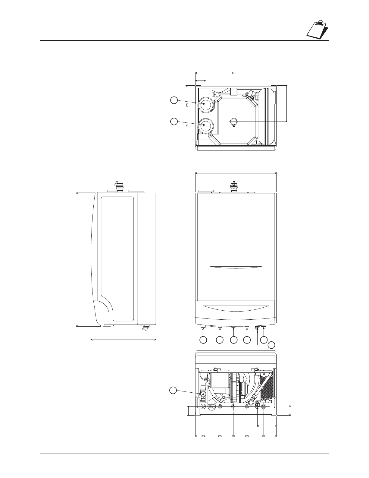
1.2 Structural charateristics
Dimensions and connections
Key
1 Heating outlet
2 Domestic hot water outlet
3 Gas inlet
4 Domestic hot water inlet
5 Heating return
6 Drain cock
7 Safety valve
8 Flue gas outlet
9 Air inlet
Fig. 1
Page 6

ARENA 30 C
6
114
213
14
220 16 136 151 194
32
216
56
44
69
70
215
214
179
161
217
191
186
49
34
35
Overall view and main components
Key
14 Safety valve
16 Fan
32 Heating pump
34 Heating temperature sensor
35 Auto air vent.
44 Gas valve
49 Safety thermostat
56 Expansion vessel
69 Flue gas outlet pipe
70 Air intake pipe
114 Water pressure switch
136 Flow-meter
151 System drain cock
161 Condensing heat exchanger
179 Non-return valve
186 Return sensor
191 Flue gas temperature sensor
194 Domestic hot water heat exchanger
213 Flexible inlet air pipe coupling
214 Flue gas outlet reducer
215 Air inlet reducer
216 Domestic hot water pump
217 Boiler body lagging
220 Ignition board
Fig. 2
Page 7

ARENA 30 C
7
Heating
outlet
Domestic
hot water
outlet
Gas
inlet
Domestic
hot water
inlet
Heating
inlet
Air
inlet
Flue gas
outlet
1644
56
49
191
136
32
34
186
22
82
188
216
114 14
Condensation
discharge
42
221
179
194
179
Key
14 Safety valve
16 Fan
22 Main burner assembly
32 Heating pump
34 Heating temperature sensor
42 Domestic hot water temperature sensor
44 Gas valve
49 Safety thermostat
56 Expansion vessel
82 Detection electrode
114 Water pressure switch
136 Flow-meter
179 Non-return valve
186 Return sensor
188 Ignition electrode
191 Flue gas temperature sensor
194 Domestic hot water heat exchanger
216 Domestic hot water pump
221 Bypass cock
Hydraulic diagram
Fig. 3
Page 8

ARENA 30 C
8
Heating
Maximum operating temperature, heating °C
Maximum operating pressure, heating bar
Minimum operating pressure, heating bar
Expansion vessel capacity litri
Expansion vessel pre-fill pressure bar
Boiler total water content litri
Domestic hot water
Domestic hot water supply ∆t 25°C l/min
Domestic hot water supply ∆t 30°C l/min
Domestic hot water supply ∆t 35°C l/min
Range of temperature regulation, domestic hot water °C
Maximum operating pressure, domestic hot water bar
Minimum operating pressure, domestic hot water bar
Dimensions, weights, conections
Height mm
Width mm
Depth mm
Empty weight kg
Gas system connections poll.
Heating system connections poll.
Domestic hot water circuit connections poll.
Condensation discharge (flexible pipe) mm
Maximum length separate flues D=80*
m
eq
(*Values expressed in equivalent air metres - refer to FERROLI calculation system)
Electrical power supply
Max Electrical Power Consumption W
Pump electrical power consumption (Speed I-II-III) W
Power supply voltage/frequency V/Hz
85
3
0,8
12
1
11,8
17,5
14,6
12,5
40 - 65
6
0,25
760
460
368
55
1/2”
3/4”
1/2”
15x20
100
150
48-67-93
230/50
Power
Heat rate Hi
Heat rate Hs
Natural Gas rate (G20)
Natural gas supply pressure (G20)
LPG Gas rate (G31)
LPG Gas supply pressure (G31)
Pmax Pmin
kW 31,5 8,2
kcal/h 27.090 7.052
nm
3
/h 3,27 0,80
mbar 20 20
kg/h 2,44 0,60
mbar 37 37
Useful heat output 80°C - 60°C
Useful heat output 50°C - 30°C
Combustion
CO2 (Natural Gas - G20) %
CO2 (LPG - G31) %
Flue gas temperature 80°C-60°C °C
Flue gas temperature 50°C-30°C °C
Flue gas flow rate kg/h
Quantity of condensation kg/h
pH of condensation water pH
Pmax
9,5
10,2
70
40
49
3,3
Pmin
9,0
9,5
65
32
13
1,4
4,1
kW 30,9 7,6
kcal/h 26.574 6.536
kW 34,3 8,4
kcal/h 29.498 7.224
kW 30,0 7,4
kcal/h 25.800 6.364
1.3 Technical data table
Page 9

ARENA 30 C
9
6,0
III
I
I
0,0
1,0
2,0
3,0
4,0
5,0
0 0,5 1 1,5 2 2,5 3
Q (m3/h)
3,5 4
H (m C.A.)
1.4 Diagrams
Heating pump head
Loss of boiler pressure
Fig. 4
Fig. 5
6,0
41,5 2 2,5 3 3,5
Q (m3/h)
1,0
2,0
3,0
4,0
5,0
1
0,0
0 0,5
H (m C.A.)
Page 10

ARENA 30 C
10
13
12
151412111087654
1245678101112
NL
321
24 V AC
24 V AC
X2
X1
131415
X5
X6
175
X10
X11
PC
3 2
X3
X4
123
6789101112
S4575B 1033
121110
87542
1
9
6
16
-
-
+
Output
-
-
DMF04
NL
L
N
NL
42
114
121110987654321
X7
----
191
72
32
98
216
186
188 82
34
136
139
138
49
4
5
NL
230 V
50 Hz
230 V
50 Hz
83
101
230V 50Hz Low voltage
Eco/Comfort
selection
12
1
DHW
disable switch
Key
16 Fan
32 Central heating pump
34 C.H. flow temperature sensor
42 D.H.W. temperature sensor
49 Overheat cut-off thermostat
72 Room thermostat (not fitted)
82 Ionisation electrode
83 Full sequence automatic control
98 Switch
101 Main P.C.B.
114 Water pressure switch
136 Flowmeter
138 Outside temperature sensor
139 Room unit (not fitted)
175 Transformer
186 Return temperature sensor
188 Hot surface igniter
191 Exhaust temperature sensor
216 Domestic hot water pump
1.5 Functional flow chart
Fig. 6
Page 11

ARENA 30 C
11
2. INSTALLATION
2.1 General Instructions
Gas Safety (Installation & Use) Regulations: 1996
In the interest of safety, it is the law that all gas appliances are installed by a competent person in accordance
with the above Regulations, Building Regulations/Building Standards Scotland, Codes of Practice, current
I.E.E. Regulations and the byelaws of the
Local Water Undertaking. Failure to comply
with the Regulations may lead to prosecution;
it is your responsibility to ensure that the law
is complied with.
N.B. For Northern Ireland the rules in force
apply.
IMPORTANT If the boiler is to be fitted in
a timber framed building it
should be fitted in
accordance with the
Institute of Gas Engineers
document IGE/UP/7. If in
doubt advice should be
sought from the Local
Supplier.
WARNING!! This appliance must be installed
in a room with sufficient ventilation, to avoid
dangerous conditions arising in the event of,
even minor, gas leaks. These safety standards
are imposed by the EEC Directive no. 09/396
for all gas appliances, including the so-called
sealed appliances.
2.2 Positioning and wall
mounting
The installation of the ARENA must be on a
suitable non-combustible load bearing wall
which will provide an adequate fixing for the
boiler mounting bracket assembly. The location should be in an area where the water
pipes will not be subjected to frost conditions.
In siting the combination boiler the following
limitations must be observed:
The combination boiler may be installed in any
room or internal space, although particular attention is drawn to the requirements of the current I.E.E. wiring
regulations and in Scotland the electrical provisions of the building regulations applicable in Scotland, with
respect to the installation of the combination boiler in a room or internal space containing a bath or shower.
Where a room sealed appliance is installed in a room containing a bath or shower any electrical switch or
appliance control utilising mains electricity must be situated so that it cannot be touched by a person using
the bath or shower.
The boiler is supplied ready for wall-hung installation. The rear frame of the appliance has a series of slots
> 50 cm
Minimum Recommended
A
B
D
3 cm
15 cm
1,5 cm
(from any openable panel)
15 cm
30 cm
C 10 cm 15 cm
A A
B
D
C
Fig. 7a
Page 12

ARENA 30 C
12
108
68
12345
6
Key
1 Heating outlet
2 Domestic hot water outlet
3 Gas inlet
4 Domestic hot water inlet
5 Heating return
6 Drain cock
Fig. 8
for fastening it to the wall, using screws with metal wall plugs.
The fastening to the wall must provide stable and effective
support of the appliance.
The boiler must be fastened to a closed part of wall, which is
free of apertures or holes behind the frame of the boiler that
may allow the internal components of the boiler to be reached.
If the appliance is enclosed in a cabinet or alongside another
appliance, space must be allowed for normal maintenance
operations. Fig. 7a shows the minimum and recommended
space to be left free around the appliance.
The boiler is supplied with a paper drilling template used to
trace the holes for fastening the appliance onto the wall.
Furthermore, upon request a metal version of the wall drilling
template is available, which can be reused for more than one
appliance.
Position the drilling template on the part of the wall chosen
for the installation of the boiler; using a spirit level, check that
the lower bracket is perfectly horizontal. Temporarily fasten
the drilling template to the wall using some adesive tape.
Trace the fastening points “A”. Drill two 10 mm holes 90 mm
deep to accept the wall plugs, fit wall plugs. Fit two special
wall plugs on the wall as described in the fig. 7c. Fasten the
wall bracket to the wall using an antitheft nut on the right side
and a standard nut (M8) on the left side. Mount the boiler on
the wall bracket and fix using an antitheft nut on the left side
and a standard nut (M8) on the right side.. The connection for
the water and gas pipes to the boiler are then
defined, from “B” lines (for vertical connections) or
from ”C” holes for horizontal connections (using
optional Ferroli kit).
Note If there is no drilling template for mounting
the appliance, simply fasten the boiler to
the wall using suitable support screws with
metal wall plugs, through the holes in the
boiler frame.
2.3 Connection to the hydraulic system
Make the connections to the corresponding couplings, according to the positions indicated in Fig. 3.
Arena
30 A
748
460
44 109,5 62 62 109,5 73
16 16
11
16
205
220
60
110120
8
9
7511061,561,511045
139
368
760
460
1 2 3 4 5
6
115
Ø 3/4” Ø 1/2” Ø 3/4”
Kit Ferroli
cod. 1KWMA78Y
A
A
B
C
Fig. 7b
Fig. 7c
Page 13

ARENA 30 C
13
In addition, shut-off valves should be installed between the boiler and the heating system to allow, if
necessary, the boiler to be isolated from the system. If a non-return valve is also installed in the domestic hot
water circuit, a safety valve must be fitted between the boiler and this circuit.
The discharge of the safety valve must be connected to a funnel or collection pipe, to avoid water leaking
onto the ground in the event of excessive pressure in the heating circuit.
Make the connections to the boiler so as its internal pipes are not subject to stress. For proper operation and
long-life of the boiler, the hydraulic system must be correctly proportioned and always complete with all the
accessories required to guarantee regular operation and conduction.
Upon request a connection kit can be supplied, simplifying connection to the system.
2.4 Characteristics of the boiler water
In the presence of water with hardness above 18 Clarke degrees, the water should be suitably treated, to avoid
any deposits in the boiler caused by hard water, or corrosion caused by aggressive water. It should also be
remembered that even minor deposits measuring just a few millimetres thick can cause, due to their low
thermal conductivity, significant overheating of the walls of the boiler, with consequent and serious problems.
The water must always be treated in the case of very large systems (with high water capacity) or systems with
the frequent inlet of recovered water. If, in these cases, the system needs to be partially or completely
emptied, it must be refilled with treated water.
Water System
Note The boiler is designed for sealed systems only and must NOT be used on open vented systems.
Central Heating
Detailed recommendations are given in BS6798, BS5449, BS6700 and CP342 Part 2. Pipework not forming
part of the useful heating surface should be insulated to prevent any heat losses or possible freezing (i.e. in
roof spaces or ventilated underfloor spaces). Drain taps should be positioned at the lowest point of the
system in accessible locations to permit the whole system to be drained down. The drain taps should be in
accordance with BS2879. Copper tubing to BS2871, Part 1 is recommended for water carrying pipework.
Pipework in horizontal runs should have a gradient where possible to facilitate the removal of air. Ensure that
the boiler heat exchanger is not a natural point for air collection.
Make Up Water
Provision must be made for replacing water lost from the sealed system. Reference should be made to
BS6798, for methods of filling and making up sealed systems. There must be no direct connection between
the boiler's central heating system and the mains water supply. The use of mains water to charge and
pressurise the system directly, is conditional upon the Local Water Byelaws. Again any such connection must
be disconnected after use.
Domestic Hot Water
Always fit a scale reducer in "hard water areas" (18 clarke degrees or over)". A 15mm copper connection
point on the boiler for attaching to the main supply is provided. The maximum domestic water pressure for
the inlet supply is 10 bar (145 P.S.I.). If the cold mains supply exceeds 5 bar (72 P.S.I.), a water governor
or pressure reducing valve must be fitted by the installer into the mains supply in an inconspicuous but
accessible position preferable between 3 and 5 metres (10-16ft) before the appliance. Such a valve must be
approved by the Water Research Council.
Attention - is drawn to the Model Water Byelaws.
Fittings manufactured from duplex (alpha-beta) brass are not acceptable for underground use and certain
water undertakings will not accept their use above ground.
Ensure all pipework is adequately supported.
Page 14

ARENA 30 C
14
2.5 Connection to the gas system
If necessary the local Gas supplier should be consulted, at the installation planning stage, in order to establish
the availability of an adequate supply of gas.
An existing service pipe must not be used without prior consultation with the Local Gas supplier.
A gas meter can only be connected by the Local Gas supplier, or by a Local Gas suppliers Contractor.
Installation pipes should be fitted in accordance with BS6891-1988.
Appliance inlet working pressure must be 20mbar MINIMUM, for NG and 37 mbar minimum for LPG.
Pipework from the meter to the combination boiler must be of an adequate size.
The boiler requires 2.73m3/h of natural gas, and 2,00 kg/h of LPG.
Do not use pipes of a smaller size than the combination boiler inlet gas connection.
The complete installation must be tested for gas soundness and purged as described in BS6981-1988. All
pipework must be adequately supported. An isolating gas valve is provided and should be fitted on the boiler
gas inlet. Please wait 10 minutes when lighting from cold before checking gas rate. Gas pressures should be
checked after the boiler has operated for 10 minutes to reach thermal equilibrium.
2.6 Condensation discharge connection
The boiler must be connected to the condensation discharge siphon, supplied as standard with the appliance.
1) Take out the flexible grey condensation discharge pipe A, already mounted in the boiler, from the proper
slot on the bottom;
2) Place the siphon on the wall, fix it to the wall with a screw + plug through the fixing point B;
3) Connect the grey pipe A to the hose connector E on the top of siphon, cutting it to the right length if
necessary;
4) Connect the corrugated pipe C to the bottom connector D;
5) Before definitively connecting the corrugated pipe C to the drainage system, fill the siphon with about 0,5
litres of water
Attenzione:
Riempire il sifone con
acqua prima di
collegarlo
A
Fig. 9
B
E
C
D
Attention:
Fill the siphon with
water before connecting
Page 15

ARENA 30 C
15
EDCBA
123456789101112
2.8 Room thermostat, external
unit and auxiliary controls
Below the electrical control box is a multipolar
terminal block, for connecting:
• Room thermostat (1-2)
WARNING: THE ROOM THERMOSTAT MUST
NOT HAVE LIVE CONTACTS. CONNECTING
230V TO THE ROOM THERMOSTAT TERMINALS WILL CAUSE IRREVERSIBLE DAMAGE
TO THE ELECTRONIC BOARD.
When connecting a room thermostat with daily
or weekly program, or a timer, avoid taking the
power supply to these devices from their switch
contacts. Their power supply must derive from
a direct connection to the mains or using batteries, depending on the type of device.
This appliance can also operate without a room
thermostat, yet the latter is recommended for
increased comfort and greater energy savings.
• Switch for economy/comfort remote selection (3-
4). With the switch turned off the boiler is maintained in “Comfort”, independently from the
setting on the menu or on the remote control.
• DHW exclusion switch (5-6) for remotely disable the DHW function. Open contact will exclude DHW.
• External temperature probe (7-8)
With the probe (optional) connected, the boiler
works in outside compensation temperature
mode, depending on the compensation curve
settled (ref. 4.11). If none probe is connected,
the boiler works in standard mode and setting
of a compensation curve (parameter 9 of menu)
is ignored by the control system.
• Remote control (9-10), for remote control and regulation of the boiler, with weekly chronothermostat
and climatic regulation functions.
To make these connections, unscrew the four
screws which fasten the lower protective plate
and connect the wires to the terminal block,
respecting the position of the terminals (refer to
the wiring diagrams, chap. 1.5)
Fig. 10 a
Fig. 10 b
Fig. 10 c
A Room thermostat
B Eco/Comfort selection switch
C Domestic hot water exclusion switch
D External temperature sensor
E Remote control
2.7 Electrical connections
Power supply
The boiler must be connected to a single-phase, 230 Volt-50 Hz power line, with max 3A fuses fitted between
boiler and the line, as well as a bipolar switch ON/OFF with contacts whose opening is at least 3 mm. The
boiler must always be properly earthed.
When electrically connecting the boiler to an electrical system with live and neutral, THE POLARITY MUST BE
RESPECTED (LIVE: brown wire / NEUTRAL: blue wire / EARTH: yellow-green). Note: If replacing the electrical
power cable, use only the “HAR H05 VV-F” cable, 3x0.75 mm2, with a maximum external diameter of 8 mm.
Page 16

ARENA 30 C
16
Fig. 12
Fig. 11
2.9 Positioning the external probe
The external probe is best installed on a wall facing north, north-west or which borders the majority of the
main living area. The probe must never be exposed to the early morning sun, and, in general and where
possible, must not receive direct sunlight; if necessary, it should be shielded.
The probe must not in any case be fitted near windows, doors, ventilation openings, flues, or sources of heat
which may alter the reading.
Note: The maximum length allowed for the electrical cable connecting the boiler to the external probe is
50 m. A common two-lead cable can also be used.
H
1/2H
1/2H
H
N
N W
Page 17

ARENA 30 C
17
2.10 Flues
Arena is a type-C boiler with forced draught, the air inlet and the flue gas outlet must be connected to one
of the exhaust–intake systems indicated as follows. Using the tables and the methods of calculation
described, first verify, before installation, that the flues do not exceed the maximum allowed length.
2.11 Connection to concentric pipes
An aluminium “60/100 concentric adapter” is available for connecting the boiler to 60/100 mm concentric
pipes. The extreme ease of mounting and the use of double-lip gaskets in the couplings makes this solution
extremely advantageous and safe. Furthermore, an aluminium and plastic concentric kit is available for
discharge using 80/125 concentric pipes.
The total length in linear metres of the concentric pipes must not exceed the maximum length indicated in
the first table below. The second table shows the reductions to be used for any bends in the pipes, excluding
the initial one.
For installation, connect the concentric kit directly to two diameter 80
bell-shaped reducers in the boilers, as indicated in Fig. 13. The
concentric kit can then be connected directly to a concentric bend
using a horizontal pipe or a concentric pipe in the vertical position.
Maximum allowable pipe length
Ø100/60 mm concentric
Arena 30 C 12 m
Vertical
11 m
Horizontal*
Reducers for concentric bends
90° concentric bend
45° concentric bend
1 m
0,5 m
Ø125/80 mm concentric
21 m
Vertical
20 m
Horizontal*
Fig. 13
1KWMA55Y
1KWMA57W
1KWMA35W
Ø 100
Ø 60
Øi 100
Øi 60
Page 18

ARENA 30 C
18
To locate the centre of the hole for the passage of the pipes in the wall, refer to Fig. 14:
Please consider that the horizontal concentric piping must have a slope towards the boiler of at least 3 mm/
m, to allow the condensation which forms in the flues to flow back to the boiler, and avoid external dripping.
The concentric pipes should be sealed with the relative pipe coupling seal at the points of coupling to the
wall. The external piping must protrude from the wall between 10 and 60 mm (Fig.15).
Fig. 14
Fig. 15
3°
60
110
142
Page 19

ARENA 30 C
19
Upon request, a wide range of pipes, bends and accessories can be supplied. For the various components,
refer to tables 1 – 2 – 3 or to the flue accessory catalogue.
A simple calculation can be performed to ensure that the maximum allowable pipe length is not exceeded:
1 For each component, table 1 – 2 – 3 lists the loss of pressure in “equivalent air-metres”, depending
on the position of installation of the component itself (air intake or flue gas exhaust, vertical or
horizontal).
The loss is called “equivalent air-metres” as it relates to the loss of a metre of air intake pipe (defined
as being equal to 1). For example, a 90° Ø80 bend in flue gas exhaust has a loss equivalent to 2.5
air-metres, that is equal to 2.5 linear metres of air intake pipe.
2 Once having completely defined the layout of the double flue system, add the losses in equivalent-
metres, according to the position of installation of all the components and accessories in the system
3 Check that the total loss calculated is less than or equal to 100 equivalent metres, that is the maximum
allowable for this model of boiler.
If the flue system chosen exceeds maximum allowable limit, some sections of the pipes should be
larger in diameter.
2.12 Connection to separate pipes
The separate Ø60 pipes for air intake and flue gas exhaust can be connected directly to the boiler, as shown
in Fig. 16a. Separate Ø80 pipes can be connected directly, once the two 80/60 (optional) reducers have been
fitted inside the boiler (Fig. 16b).
Ø60 Ø60
Flue Air
Ø80 Ø80
Ø80 Ø80
Flue Air
Fig. 16 a Fig. 16 b Fig. 16 c
Page 20

ARENA 30 C
20
2.13 Table of losses for piping and accessories
KWMA83U
KWMA86A
KWMA85A
KWMA86U
KWMA84U
Air Flue
Vertical
Horizontal
Vertical
Horizontal
KWMA01K
KWMA02K
KWMA05K
KWMA82A
KWMA38A • 0,50 m
KWMA83A • 1,00 m
KWMA06K • 2,00 m
KWMA07K • 4,00 m
Description
Tubo Ø 80
male-female
Female-female
bend 45° Ø 80 mm
Female-female
bend 90° Ø 80 mm
Male-female
bend 90° Ø 80 mm
Pipe fitting M/M/F Ø80
with inspecting
plug+trap for
condensate drainage
system
Description
Airwall terminal
products of
combustion Ø80 mm
Air terminal of inlet
protection Ø80 mm
Outlet flue air inlet
for concentric system
Ø80
Pipe fitting for
outlet flue Ø80 mm
Outlet flue air inlet
for connection with
split end Ø80 mm
0,5
1
2
4
0,5
1
2
4
0,8
1,6
3,2
6,4
1
2
4
8
1,2 1,8
2,0 2,5
1,5 2,0
7
Reduction
KWMA55U
5
2
4
3
Air Flue
Vertical
Horizontal
Vertical
Horizontal
Reduction
12
Condensate flue
outlet
KWMA03U
Spigot and socket
reduction Ø 80/100 mm
0
Accessories Ø 80 Accessories Ø 80
Tab. 2
The loss values listed refer to original FERROLI
pipes and accessories
Tab. 1
Page 21

ARENA 30 C
21
Air Flue
Vertical
Horizontal
Vertical
Horizontal
Description
3 3 4,0 4,5
3 4,5
4 5,2
Reduction
9
0
Accessories Ø 60
Air/flue wall terminal
Ø60 mm
KWMA90A
Male-female
bend 90° Ø 60 mm
KWMA88W
Male-female
bend 45° Ø 60 mm
KWMA39W
Male-female
flue Ø 60
KWMA89W • 1,00 m
5
KWMA02W
Spigot and socket
reduction
Ø 60/80 mm
Tab. 3
Page 22

ARENA 30 C
22
Fig. 17
For other accessories please refer to the manual: “Flue accessories and installation of forced air appliances”
Example of how to calculate the connection of two separate pipes, max flue length: 100 metres
The flue and air pipes must be sloped towards the boiler by at least 3%.
Ref.
1
2
3
N° Pieces
20
20
1
Vertical flue pipe
Vertical air pipe
Flue
Description
Length
o loss
32 m
20 m
12 m
64 mTotal
20 m
12
3
Page 23

ARENA 30 C
23
2.14 Terminal Position
Fig. 18
P
D, E
Q
Q
l
B
C
A
G
F
L
J
H
H
K
N
N
MM
Q
Directly below an opening, air brick, (0-7 kW)
opening windows, etc. (>7-14 kW)
(>14-32 kW)
(>32-70 kW)
Above an opening, air brick, (0-7 kW)
opening windows, etc. (>7-14 kW)
(>14-32 kW)
(>32-70 kW)
Horizontally to an opening, air brick, (0-7 kW)
opening windows, etc. (>7-14 kW)
(>14-32 kW)
(>32-70 kW)
Below gutters, soil pipes or drain pipes
Below eaves
Below balconies or car port roof
From a vertical drain pipe or soil pipe
From an internal or external corner
Above ground roof or balcony level
From a surface facing the terminal
(also see 6.1.2)
From a terminal facing the terminal
From an opening in the car port ( e.g. door,
window) into the dwelling
Vertically from a terminal on the same wall
Horizontally from a terminal on the same wall
From the wall on which the terminal is mounted
From a vertical structure on the roof
Above intersection with roof
Dimensions Terminal position
(kW input expressed in net)
Balanced flues room
sealed
Open flues
Natural
draught
Natural
draught
Fanned
draught
Fanned
draught
A
a
300 mm
600 mm
1500 mm
2000 mm
300 mm Not allowed 300 mm
B
a
300 mm
300 mm
300 mm
600 mm
300 mm Not allowed 300 mm
C
a
300 mm
400 mm
600 mm
600 mm
300 mm Not allowed 300 mm
D 300 mm 75 mm Not allowed 75 mm
E 300 mm 200 mm Not allowed 200 mm
F 600 mm 200 mm Not allowed 200 mm
G 300 mm 150 mmbNot allowed 150 mm
H 600 mm 300 mm Not allowed 200 mm
I 300 mm 300 mm Not allowed 300 mm
J 600 mm 600 mm N/A 600 mm
K 600 mm 1200 mm N/A 1200 mm
L 1200 mm 1200 mm N/A 1200 mm
M 1500 mm 1500 mm N/A 1500 mm
N 300 mm 300 mm N/A 300 mm
O N/A N/A N/A 50 mm
P N/A N/A See Table 2
and Fig. 6b
N/A
Q N/A N/A See Table 2
and Fig. 4
150 mm
NOTE N/A = Not applicable
a
I
n addition, the terminal should not be nearer than 150 mm (fanned draucht) or 300 mm (natural draught) to an opening in the building fabric formed for the purpose of accommodating
a built-in element such as a window frame, (see Figure C2). Separation distances are linked to the rated heat inputs as shown.
b
This dimension may be reduced to 75 mm for appliances of up to 5 kW heat input.
Minimum dimensions of flue terminal positions
Page 24

ARENA 30 C
24
Supply gas Restrictor
Methane (G20)
Propane (G31)
-
Ø 5,2 mm
Category
2H
3P
Nominal CO2 at maximum power
9,5 %
10,2 %
3.
SERVICE AND MAINTENANCE
3.1 Settings
Gas conversion
The adjustment and transformation operations must only be performed by Qualified Personnel.
FERROLI S.p.A. declines all liability for damage to persons and/or things deriving from tampering with the
appliance by non-authorised persons.
The appliance can operate with natural or LPG supply gas, and is factory configured for use with one of the
two gases, as is clearly marked on the packaging and on the rating plate on the appliance itself.
If the appliance has to be used with a gas other than the one it has been set for, it is necessary to insert (or
remove) the restrictor between the gas valve and the air inlet Venturi, and operate on the regulation screw
F (fig. 19) placed on the Venturi unit to regulate the CO2 content in the flue gas to the nominal value (within
+/- 0.1%) described in the following table::
To convert, proceed as follows:
1 Remove the lower protection plate and open the boiler casing
2 If necessary, insert or remove the restrictor following the instructions to points 3-11, otherwise go
to point 12
3 Disconnect the gas and the electrical power supply if the boiler is already installed
4 Remove the ignition device “A” from the valve body, removing the fastening screw ”B”
Fig. 19
C
D
B
A
F
Page 25

ARENA 30 C
25
5 Unscrew the union nut between the gas valve and the gas inlet pipe
6 Remove the flexible inlet air pipe from the Venturi mouthpiece on the fan
7 Unscrew the fastening screws “C” and remove the Venturi unit + gas valve
8 Unscrew the three fastening screws “D” and separate the gas valve and the Venturi
9 Replace the diaphragm “E”, making sure the new restrictor and the gasket are repositioned correctly
inside the housing in the valve body
10 Reassemble the gas valve, ignition device, connections, following the previous instructions in the
reverse order
11 Check the seal of the gas connections
12 Insert the probe of a combustion analyzer in the outlet flue gas of the boiler
13 Turn on the boiler and bring the burner to the maximum power: it is advised to open one or more
DHW taps and verify on the display that the parameter 8 (boiler power) arrives to 99.
14 By means of the analyzer, note the CO2 content in the flue gas with boiler to maximum power
15 If necessary, slowly operate on the regulation screw F (fig.19) placed on the Venturi to bring the CO
2
content to the nominal value (within +/- 0.1%) expected in the table for the correspondent gas type.
It is recommended to operate only on the screw F and not on the gas valve: this operation could
compromise the correct functioning of the appliance
16 Once the regulation has been made, apply the orange plate contained in the transformation kit next
to the data plate and reassemble the boiler casing and the lower protection plate.
Fig. 20
E
Page 26

ARENA 30 C
26
∆t setting
The thermal head ∆t, that is the difference in heating water
temperature between the central heating outlet and return, can be
set by varying the speed of the pump system (Fig. 21- A). Note that
an increase in speed corresponds to a reduction of the ∆t, and viceversa. The curve of flow rate/ head of the standard pump is shown
in Chapter 1.
To fully exploit the advantages of condensation, the central heating
return inlet should work at low temperatures, possibly below
45-50 °C. The boiler will also work correctly at higher return
temperatures, but in this case the temperature of the flue gas outlet
is near to or above the dew point, with consequent reductions in
condensation.
One specific feature of the ARENA boiler is the possibility to work
with high ∆t, up to 50°C. This feature can be exploited to maintain
a low central heating return inlet temperature even when the
required outlet temperature is high, and thus allow the appliance to
operate in full condensation mode.
Bypass setting
The boiler is fitted with a bypass between the outlet and return,
which guarantees minimum circulation inside the appliance even
with systems fitted with full-closing thermostatic zone valves. To
adjust the bypass, use a screwdriver on the adjustment cock,
operating from the bottom of the boiler
Adjusting the hydraulic system pressure
The fill pressure with the system cold, read on the boiler hydrometer “B”, must be around 1.5 bar. If the
system pressure falls during operation (caused by the evaporation of the gases dissolved in the water) to
values below the minimum described above, reset the initial value. For correct boiler operation, the pressure
inside, when hot, must be around 2 – 2.5 bar.
Fig. 21
Fig. 22
A
B
Page 27

ARENA 30 C
27
3.2 Commissioning and testing
The appliance must only be set-up for use by Qualified Personnel, such as personnel from Technical
organization.
Checks to be performed during the first ignition, and after all maintenance operations which may have
required the disconnection of the systems or intervention on the safety devices or parts of the boiler:
Before igniting the boiler:
• Open any shut-off valves between the boiler and the systems
• Check the seal of the gas system, proceeding with care and using a soapy water solution to find any leaks
from the connections.
• Fill the system as indicated earlier and ensure that the air contained in the boiler and the system has been
completely vented, by opening the air bleeding valve on the top of the appliance (Fig. 2) and any bleeding
valves in the system.
• Check that there are no water leaks in the heating system, in the domestic hot water circuits, in the
connections or in the boiler
• Check the correct connection of the electrical system
• Check that the appliance is properly earthed;.
• Check the correct connection of the appliance to the system for draining the condensation and the
functioning of the condensation drain system itself.
• Check that the pressure value and gas rate for the heating system are correct.
• Check that there are no flammable liquids or materials in the
immediate vicinity of the boiler
• Check that the non-return valve is operating (fig. A)
Igniting the boiler:
• Open the gas cock upstream from the boiler.
• Bleed the air in the pipe upstream from the gas valve.
• Close any switches or insert any plugs upstream of the boiler
• Place the main switch in the ON position.
• The boiler will switch on and perform a complete self-test cycle
lasting around one minute, to check the operation of the main parts. The display shows, in sequence:
Software version
Parameter version
Operation in test - ( )
• If the cycle is performed correctly:
- If domestic hot water or heating is not required, the display shows a small “o“ (standby mode) followed
by the temperature value of the outlet sensor. Then use the room thermostat or remote control to
activate the request for heating
- If there is a request, the display will pass from the standby phase “ o “ to the heating phase “ c “ and
the boiler will automatically begin operation, controlled by its regulation and safety devices.
- If anomalies arise during the self-test cycle or the successive ignition phase, the display will show the
corresponding error code and the boiler will shut-down. Wait around 15 seconds and then press the
reset button. The boiler will repeat the ignition cycle. If, after a second attempt, the boiler does not start,
refer to the paragraph on “Troubleshooting” 3.5.
Note In the case of power failures while the boiler is in operation, the burner assembly will switch off. On
the return of mains power, the boiler will again perform the self-test cycle, following which the burner
assembly will automatically restart (if there is still a request for heat).
operating
locked
fig. A
Page 28

ARENA 30 C
28
Checks during operation
• Ensure there are no gas or water leaks.
• Check the efficiency of the flues and air-flue gas pipes during the operation of the boiler.
• Check that the water circulation between the boiler and the systems is correct.
• Ensure that the gas valve modulates correctly both in the heating phase and the production of domestic
hot water.
• Check the correct ignition of the boiler, effecting a series of ignition and shut-down tests using the room
thermostat or the remote control.
• Ensure that the consumption of the fuel indicated by the counter corresponds to the values indicated in
table at pag. 8.
• Check that there is the correct flow rate of domestic hot water with the ∆t declared in the table: do not
rely on measurements effected using empirical systems. The measurements should be made using special
instruments at a point as close as possible to the boiler, considering the dispersion of heat from the piping.
• Ensure that without the request for heating the burner assembly turns on correctly on opening a domestic
hot water tap. Check that during operation in heating mode, on opening a domestic hot water tap, the
heating pump switches off, the domestic hot water pump starts and there is regular production of
domestic hot water.
• Check the correct setting of the parameters and effect any custom settings required (compensation curve,
heat rates, temperatures, etc.)
Shut-down
Close the gas cock upstream from the boiler and disconnect the electrical power supply to the appliance.
Warning - For long periods of inactivity during the winter months, in order to avoid damage due to freezing,
all the water should be drained from the boiler, both the domestic hot water and the heating system;
alternatively, drain only the domestic hot water and introduce the relative antifreeze into the heating system.
3.3 Maintenance
The following operations must only be performed by Qualified Personnel, such as personnel from our
Technical organization.
Seasonal checks on the boiler and the flue
The following checks should be made on the appliance at least once a year:
• The control and safety devices (gas valve, flow-meter, thermostats, etc.) must be working properly.
• The pipes and the air-flue gas terminals must be free of obstacles and not contain any leaks.
• The condensation draining system must be efficient and must not contain any leaks or blockages
• The gas and water systems must be perfectly sealed.
• The burner assembly and the heat exchanger must be clean. Follow the instructions in the next paragraph.
• The electrodes must be free of deposits and positioned correctly.
• The pressure of the water system when cold must be around 1 – 1.5 bar; if not, reset this value.
• The expansion vessel must be full.
• The circulation and domestic hot water pumps must not be blocked.
Page 29

ARENA 30 C
29
Cleaning the boiler body and the burner assembly
The burner assembly and the parts of the boiler
body in contact with condensation should be
cleaned once a year. To clean these parts, use
soft brushes or compressed air; do not use
chemical products or steel brushes.
To dismount the burner assembly and access
the boiler body, proceed as follows:
1. Close the gas supply cock and disconnect
the electrical power supply
2. Remove the lower protection plate and
the boiler casing
3. Disconnect cables “G” and “H” of the
electrodes from the ignition devices, Fig.
23a
4. Remove the ignition devices from the valve body, unscrewing screw “A”
5. Loosen the two fastening screws “B” and
slide the control panel support bracket
“C” and all the wiring forward. Fasten the
bracket in the position of maximum
extension
6. Disconnect the gas valve from the gas inlet
pipe, unscrewing the union nut behind the
valve, disconnect the flexible inlet air pipe
coupling “E” from the fan and the
compensation pipe “F” from the gas valve.
7. If there is less than 30 centimetres free
space below the fan, remove the fan-gas
valve unit by unscrewing the 4 fan fastening
nuts. If the space is greater, this is not
necessary, and the entire unit can be
removed together with the burner
assembly hexagonal support base (see
following points).
8. Progressively unscrew the 3 fastening nuts
“L”. Once removed, the unit “M” - burner
assembly, electrodes, hexagonal support
base - can be removed from the boiler
body as indicated in the series of images
23d - 23g. Intervene with care, avoiding
excessive force on the fins of the hexagonal
support base if the gasket “K” opposes
resistance due to deposits. Some drops of
water or residues may by released; avoid
where possible having these come into
contact with the electrical parts.
Fig. 23b
B
Fig. 23a
L
E
F
A
G
H
Page 30

ARENA 30 C
30
Fig. 23c
Fig. 23d
Fig. 23e
C
M
WARNING The hot wire spark electrode
is fragile! Both during and
after removal handle the
unit “M” with care to avoid
damaging the electrode.
9. The burner assembly can be cleaned in
place or removed by unscrewing the three
fastening screws on the hexagonal support
base.
10. The lower part of the boiler body – where
condensation takes place - can now be
accessed for cleaning. Carefully clean the
fins “N” and the condensation collection
and discharge area “O”.
The upper part where the burner assembly
is located does not require special
maintenance. If necessary, blow with
compressed air to eliminate small residues
of combustion.
11. Follow the previous instructions in the
reverse order and reassemble the boiler.
Always work with caution and pay special
care to all the sealing systems, especially
the gas seals and the gasket “K” between
the burner assembly hexagonal support
base and the condensation collector.
12. Once the boiler has been reassembled,
perform a complete operating test (as
specified in the previous chapter), checking
all the phases of ignition and operation,
and the correct functioning of the safety
and control devices, the sensors,
thermostats, gas valve, fan and pumps.
13. Check that there are no gas leaks, including
the parts inside the boiler (gas pipe, gas
valve connections, fan connections).
K
Page 31

ARENA 30 C
31
fig. 23g
fig. 23f
fig. 23h
N
O
Page 32

ARENA 30 C
32
Fig. 24
C
D
B
A
3.4 Replacement of parts
Initial procedure
a) The boiler is cold, electricity supply is isolated, and the gas supply is turned off at the inlet of the boiler
b) For replacement of parts where water connections are broken, it will be necessary to isolate and drain
either or both the central heating or domestic hot water circuits of the boiler only. The cold water mains
inlet is isolated at the inlet cock. The D.H.W. is drained by opening a hot tap.
The C.H. flow and return cocks are turned off at the isolation cocks. The C.H. is drained via the pressure
relief valve (twist about 1/2 of a turn) and the discharge tap on right . To ensure complete C.H. water
drainage, turn the screw of the non-return valve on “locked” position (fig. A - pag. 26)
c) Remove components following special notice below and replace in reverse order.
d) Ensure water and gas washers are in good condition.
Removing Boiler Jacket and sliding control panel
To remove the boiler jacket, unscrew the four screws on bottom of the boiler and the two screws on front
supporting the control panel. Gently pull up the jacket.
If necessary, to have more space for working, the control panel could be slid forward , loosing the two screws
“B” (fig. 23b) and pulling the support bracket “C” (fig. 23c)
Final procedure
• Re-open cocks and re-charge the system to about 1.5 bar, and vent boiler and radiators.
Re-charge to 1.5 bar if necessary.
• Upon completion of the work the following. Should be checked:
1) Gas soundness of all joints
2) Water soundness of all joints
3) The electricity supply.
4) The pressure of the sealed system and top up where necessary.
Gas valve
• Isolate gas and electricity supplies
• Remove the lower protection plate jacket
• Remove the ignition device “A” from the valve body, removing the fastening screw “B”
• Unscrew the union nut between the gas valve and the gas inlet pipe
• Remove the flexible inlet air pipe from the Venturi mouthpiece on the fan
• Unscrew the fastening screws “C” and remove the Venturi unit + gas valve
• Unscrew the three fastening screws “D” and separate the gas valve and Venturi
Page 33

ARENA 30 C
33
Fan
• Isolate gas and electricity supplies
• Remove the lower protection plate and jacket
• Remove the ignition device “A” (fig. 26) from the valve body, removing the fastening screw “B” (fig. 25)
• Unscrew the union nut between the gas valve and the gas inlet pipe
• Remove the flexible inlet air pipe from the Venturi mouthpiece on the fan
• Unscrew the four nut “A” fixing the fan (fig. 25)
• Unscrew the fastening screws “C” (fig. 24) and remove the Venturi unit + gas valve
Burner and electrodes
• Follow the “cleaning procedure” at page 29 from 1 to 8 to remove the burner assembly
• Carefully remove the hexagonal ceramic fibre
• To change the burner, remove the three fastening screw “A” (fig. 26)
• To change electrodes, unscrew the two screws to the supporting plate and remove it. Undo the brass nuts,
to electrodes “B” (fig. 27). Reassemble reverce order.
DHW Heat exchanger
• Isolate gas, electricity and water supplies
• Remove the lower protection plate and jacket. Slide forward the control panel.
• Drain water from DHW and CH circuits
• Unscrew the four A nuts connecting the heat exchanger and remove it
A
A
A
B
Fig. 25
Fig. 26
Page 34

ARENA 30 C
34
Replacement of pump head (fig. 27)
• Isolate electricity and flow and return pipes
• Remove casing
• Release pressure from boiler via pressure relief valve
• Unplug the pump lead “B” from the pump head
• Place a piece of cloth or other absorbent material over the rear
of the control panel to catch any drops of water that may fall
when the pump head is removed.
• Using a 4 mm allen wrench undo the two allen screws “C” in the
pump head, lift away pump head from the pump body
• Fit new head into pump body and secure with the allen screws
tightening evenly.
• Replace electrical connection.
Replacement of pump body (fig. 27)
• Proceed as for removal of pump head
• Disconnect the two nuts “D“ fixing the pump body
• Remove pump
• Reassemble in reverse order taking care to ensure the O-rings
are in place and undamaged.
Expansion Vessel (fig. 27)
Isolate electricity and water supplies
Remove outer case
Loosen the “E” connections to expansion vessel
Remove the expansion vessel
Re-assemble in reverse order
Re-pressure expansion vessel
(charge pressure 0,8-1 bar) through the air charging valve
Ensure pressure relief value is open
(twist about 1/2 of a turn) when repressurizing
D.H.W. temperature sensor (fig. 27)
• Isolate electricity
• Remove outer case
• Pull out sensor “F” from tube, with its spring
• Remove electrical connections from sensor
• Remove spring from sensor
• Replace in reverse order
C.H. temperature sensor, overheat cut off
thermostat and Aquafast Sensor
• Isolate electricity
• Remove outer case
• Identify the location of thermostat from fig.
28.
• Pull out thermostat or sensor from tube, with
its spring
• Remove electrical connections from sensor or
thermostat
• Remove spring from sensor or thermostat
Replace in reverse order
Fig. 27
A
F
C
D
D
E
A
B
C.H.
sensor
Fig. 28
Overheat
thermostat
Aquafast
sensor
Page 35

ARENA 30 C
35
D.H.W. flowmeter
• Isolate electricity and water supplies
• Open a hot water tap to release water pressure from the domestic side of the heat exchanger, close tap.
• Remove outer case
• Take off protective cover from main PCB and unplug flow meter lead from terminal
• Place a piece of cloth or some other absorbent material over rear of control panel to catch any drops of
water that may be released when removing the flow meter
• Using a 24mm open ended spanner, undo flow meter unions “A” and “B” (fig. 30) taking care not to twist
the copper tubing (access through base panel).
• Remove flow meter, check + clean filter + restrictor + fit to new flow meter.
• Reassemble in reverse order (fig. 30).
37 3938 38
Take care on correct position of components as reported in fig. 30
Key
37 Cold water inlet filter
38 Gasket
39 Cold water flow limiter
A
B
Fig. 29
Fig. 30
Page 36

ARENA 30 C
36
3.5 Troubleshooting
Diagnostics
The boiler features an advanced self-diagnostic system. In the case of an fault in operation, the display flashes
and the code identifying the fault appears. The faults marked with the letter “A” cause the permanent shutdown of the boiler. To reset operation the boiler must be restarted manually, pressing the “R” (reset) button.
The faults marked by the letter “F” cause temporary shut-down and are reset automatically as soon as the
value returns within the boiler’s normal operating range.
The following table lists a number of indications for resolving the faults signalled by the boiler. Interventions
on the appliance must be effected only by Qualified Personnel, such as the personnel from the FERROLI
Customer Technical Service Centre. For any operations on the appliance or which require the opening of the
boiler, always request the assistance of the service centre.
Failed burner
assembly ignition
• No gas or low gas pressure
• Ignition or detection
electrode fault
• Defective gas valve
• Check that the gas pressure or the
gas flow to the boiler is correct and
that air has been eliminated from
the piping
• Check the wiring to the electrodes
and that these are positioned
correctly and free of deposits
• Check and replace the gas valve
Safety thermostat
activation
• Outlet sensor not active
• No system circulation
• Check the correct positioning and
operation of the outlet sensor
• Check the pump
Flue safety device
intervention
• Flue partially blocked
or insufficient
• Check the efficiency of the flue,
the flue gas exhaust pipes and
the outlet terminal
No flame following the
ignition phase
• Air/flue pipes blocked
• Air in gas supply
• Low gas pressure
• PCB
• Free the obstructions from the flue,
flue gas exhaust and air inlet pipes
and terminals
• Check and purge the gas line
• Check the pipe size and meter
governor
• Check the main board
Insufficient water system
pressure
• System empty • Fill the system
Fan fault • Fan not powered
• Defective fan
• Check the wiring to
the fan
• Replace the fan
Fault Possible cause Solution
Page 37

ARENA 30 C
37
Domestic hot water sensor
faulty
• Sensor damaged or
wiring cut
• Check wiring or replace the
sensor
Flue gas sensor faulty • Sensor damaged or
wiring cut
• Check wiring or replace the
sensor
External probe faulty • Sensor damaged or
wiring short-circuited
• Check wiring or replace the
sensor
No communication between
main board and ignition devices
• Wiring cut or incorrect
between main board and
ignition devices
• Check the wiring and the
connections between the
boards
Fault Possible cause Solution
Microprocessor faulty • Microprocessor operation
faulty
• Disconnect and restore the
electrical power supply. If the
problem persists check and/or
replace the main board
High flue gas temperature • Flue partially blocked
or insufficient
• Check the efficiency of the flue,
the flue gas exhaust pipes and
the outlet terminal
Excessive central heating
outlet temperature
• Pump blocked
• Pump faulty
• Free the pump by removing the
cap and rotating the shaft with a
screwdriver
• Check or replace the condenser
or the pump
Excessive central heating
return temperature
• No system circulation
• Domestic hot water heat
exchanger dirty or
blocked
• Check system and pump
• Clean domestic hot water heat
exchanger
Outlet sensor faulty • Sensor damaged or
wiring cut
• Check wiring or replace the
sensor
Return sensor faulty • Sensor damaged or
wiring cut
• Check wiring or replace the
sensor
Page 38

ARENA 30 C
38
Display and boiler off • Power failure • Check or await the return of the
electrical power supply
Radiators cold in winter • Room thermostat
adjusted too low or
defective
• Adjust the knob to a higher
temperature, replace if
necessary
Radiators hot in summer • Room thermostat
adjusted too high or
defective
• Adjust the knob to a lower
temperature, replace if
necessary
Large variations in
domestic hot water
temperature
• Water flow rate too low • Increase the water flow rate
(minimum three litres per minute)
Fault Possible cause Solution
Low domestic hot water
flow
• Insufficient mains water
pressure
• Heat exchanger with
passages partially blocked
• Install a pressure increase
device
• Request the cleaning of the
heat exchanger
No domestic hot water
flow
• Heat exchanger
blocked
• Defective flow-meter
• Request engineer for the cleaning
operations
• Request engineer for the
replacement of the flow-meter
No temperature increase
with boiler on
• Boiler dirty
• Boiler insufficient
• Check and clean the boiler body
• Check that the boiler is the right
capacity for the requirements of
the heating system
Loss of condensation from
the boiler
• Condensation discharge
blocked
• Check and clean the drain
trap
Page 39

ARENA 30 C
39
4. OPERATING INSTRUCTIONS
4.1 Operation and controls
The Arena 30C is a pre-mix condensing thermal generator for heating and the production of domestic hot
water, using natural gas or LPG (configured at the moment of installation) and managed by an advanced
microprocessor control system.
The operation of the appliance is mostly automatic. The heat rate for the heating function is regulated
automatically by the control system according to the characteristics of the internal and external environment
(with optional external probe installed), the characteristics of the building and its location. The heat rate for
the domestic hot water function is regulated automatically and continuously, to ensure rapid delivery and
comfort in all supply conditions.
The user simply has to set the required temperature from inside the living area (using the room thermostat
or the optional, yet recommended, remote control) or set the heating system temperature and the required
outlet temperature for the domestic hot water service. The regulation and control system will then provide
for optimal operation all year round.
The display provides continuous indication on the operating status of the appliance, and can display
additional information on the temperature of the sensors, the set-point, etc. or be used for the configuration
of such via the operating menu, using the keypad.
Any anomalies in operation involving the boiler or the heating system are signalled on the display and, where
possible, corrected automatically.
Display D1 Display D2
Ignition switch
0
1
L1 L2
fig. 31
4.2 Boiler control panel
MODE button - Use this button to scroll the parameters.
RESET button - Use this button to reset the operation of the boiler in the event of shut-
down.
MODIFY button - Use these buttons to modify the regulation values.
CONFIRM button - Use this button to enable the set regulation value.
MODE display - Indicates the operating mode of the boiler or the selected parameter.
DATA display - Indicates value of the parameters
Led L1 - Indicates:Economy Operation
Led L2 - Indicates:Comfort Operation
Function of the buttons
Display indications
Page 40

ARENA 30 C
40
4.3 Ignition
Check than any shut-off valves in the heating system and domestic hot water circuit outside of the boiler are
open. Open the gas cock upstream from boiler and press the main switch. The boiler will perform an selftest cycle lasting approximately one minute, at the end of which it is ready for operation. The ignition and
shut-down of the burner assembly are completely automatic operations, which depend on the requirements
of the heating system or domestic hot water circuit.
4.4 Shut-down
In the event of extended periods of inactivity close the gas cock upstream from the boiler and disconnect
the electrical power supply to the appliance. In this case, the boiler antifreeze protection function is also
disabled; this function switches on the burner assembly when the heating system temperature falls below
5°C. For extended periods of inactivity during the winter months, in order to avoid damage due to freezing,
all the water should be drained from the boiler, both the domestic hot water and the heating system;
alternatively, drain only the domestic hot water and introduce the special antifreeze into the heating system.
4.5 Operating indications on the display
During operation, without pressing any of the buttons the display shows the operating status of the
appliance:
Operating mode
Standby
Heating
Domestic hot water
Standby following domestic hot water op.
Standby following heating op.
Waiting for DHW production
Display “D1” Display “D2/D3”
Central heating outlet temperature
Central heating outlet temperature
Domestic hot water temperature
Domestic hot water temperature
Central heating outlet temperature
Domestic hot water temperature
Summer/Winter Selection (00=Summer • 11=Winter)
Economy/Comfort Selection
CH outlet temperature view and setting
Aquafast temperature view/DHW output setting
Domestic hot water temperature
External temperature
Flue gas temperature
Domestic hot water flow rate
Boiler power
Compensation curve setting
-
DISPLAY D1 DISPLAY D2/D3
4.6 Accessing the operating menu
Pressing the “ - mode” button once accesses the operating menu. Pressing the “ - mode” button again
displays the following parameters and information in sequence:
Page 41

ARENA 30 C
41
4.7 Setting the heating system temperature
Set, using the room thermostat or remote control, the desired temperature inside the rooms. When acting
on the room thermostat, the boiler is turned on and the heating system water is brought to the central heating
outlet set temperature or calculated temperature (with temperature scrolling active). On reaching the
required temperature inside the rooms, the generator will switch off.
If no room thermostat or remote control is installed, the boiler will maintain the heating system temperature
at the central heating outlet setpoint.
To set the central heating outlet temperature, access the operating menu, and using the button display
parameter 1 – central heating outlet temperature. On pressing one of the buttons the display will start
to flash, showing the outlet temperature setpoint. Use the buttons to set the required value. To
activate the new value, press the button . To cancel the setting, do not press the button , and press
the button .
4.8 Setting the domestic hot water temperature
Set, using the control boiler panel, the required domestic hot water outlet temperature. On opening a hot
water tap, the system regulates itself to supply water at the set temperature, according to the flow rate of
delivery and the temperature of the cold water supplied to the boiler. If in terms of delivery or temperature
difference between the inlet and outlet, the thermal capacity of the generator is exceeded (refer to the
technical data), the outlet temperature will be proportionally lower than the setpoint.
To set the domestic hot water outlet temperature, access the operating menu, and using the button
display parameter 2 – domestic hot water temperature. On pressing one of the buttons the display
will start to flash and the domestic hot water outlet temperature setpoint will be displayed. Use the buttons
to set the required value. To activate the new value, press the button . To cancel the setting, do
not press the button , and press the button .
4.9 Summer/Winter Selection
For Summer/Winter selection, enter functioning menu and visualize parameter “0.” through key . In
correspondence of parameter “0.”, pressing one of keys Summer/Winter selection is visualized
(parameter “0.” flashes); through the same keys it is possible to select Summer functioning (set 00) or Winter
functioning (set 11). To activate new setting, press key , to exit without saving the selection press key .
In “Summer” mode (00) heating is excluded. Antifreeze function remains enabled.
4.10 Aquafast device
The Arena 30C is fitted with a special Aquafast device for the rapid supply of domestic hot water to the boiler
outlet. With Aquafast active, a small amount of water is maintained at temperature inside the boiler body,
in order to immediately heat the domestic hot water upon request, eliminating the waiting time for the
ignition and start-up of the boiler. The energy consumption of this device is quite limited, as its layout exploits
the residual heat generated in the heating phase; Aquafast can however be deactivated by the user in order
to operate in maximum economy.
When the Aquafast device for the ultra-fast production of domestic hot water is active (default setting), the
“Comfort” LED on the control panel is on, while when inactive, the “Economy” LED on the control panel is
on.
To deactivate Aquafast access the operating menu – parameter 0. Pressing one of the buttons , the
display starts to flash, showing 1 if the device is active, 0 if inactive. Use the buttons to set the required
value. To activate the new value press the button. To cancel the setting, do not press the button , and
press the button .
Page 42

ARENA 30 C
42
4.11 Outside temperature compensation
When the (optional) external probe is installed, the boiler regulation system functions in “Outside
temperature compensation” mode. In this mode, the temperature of the heating system is regulated
according to the external climatic conditions, so as to guarantee a high degree of comfort and energy saving
all year round. Specifically, when the external temperature falls, the central heating outlet temperature is
increased, according to a pre-determined “compensation curve”.
In this mode, the temperature set in parameter 1 of the operating menu becomes the maximum central heatin
g outlet temperature. This should be set to Maximum to allow the system to regulate over the entire working
range.
The boiler must be set during installation by qualified personnel. Other minor modifications can be made by
the user to improve the level of comfort: the compensation curve can in fact be modified by accessing the
operating menu with the button and scrolling the menu, again using the button, to parameter 9.
The set compensation curve is displayed (refer to graph below). Pressing one of the buttons the display
starts to flash; use the buttons to set the required value. To activate the new curve, press the button
. To cancel the setting, do not press the button, and press the button .
If the ambient temperature is lower than the required value, it is suggested to set a higher curve, and viceversa. Proceed with single unit increments or decreases, and check the results in the room.
Compensation curve
20
30
40
50
60
70
80
90
20 10 0 -10 -20
Temperatura esterna °C
Temperatura
di mandata impianto C°
1
2
3
4
5
6
7
8
9
10
4.12 Maintenance
It is strongly recommended to effect the annual maintenance of the heating system and at least biennial
checks of the combustion device. Please refer to the “maintenance” section in this manual.
The casing, the control panel and the aesthetic parts of the boiler can be cleaned using a soft and damp cloth.
Do not use abrasives or solvents.
4.13 Anomalies
In the event of operating anomalies or problems, the display flashes and shows the code identifying the
anomaly.
The anomalies marked by the letter “F” cause temporary shut-down, and are reset automatically as soon as
the value returns within the boiler’s normal operating range.
The anomalies marked by the letter “A” cause a shut-down of the boiler which can be reset by the user. To
reset operation, press the (reset) button.
If the problem persists, or for any other anomalies, please refer to the “troubleshooting” chapter in this
manual for more details.
Page 43

Page 44

Lichfield Road, Branston Industrial Estate, Burton Upon Trent, Staffordshire DE14 3HD
Tel. 08707 282 885 - Fax 08707 282 886
ALL SPECIFICATIONS SUBJECT TO CHANGE
Phone numbers:
Installer
Service Engineer
BECAUSE OF OUR CONSTANT ENDEAVOUR FOR IMPROVEMENT DETAILS
MAY VARY SLIGHTLY FROM THOSE QUOTED IN THESE INSTRUCTIONS.
Please note - to avoid incurring unnecessary expense, in the event of a boiler shut down, check
this in not caused by lack of electricity supply, gas supply or low water pressure before calling
our Customer Service Helpline.
Should you require help with any difficulties
call our Technical Service Helpline on
08707 282 885
IMPORTANT
"All CORGI Registered Installers carry a CORGI ID card and have a registration number. Both should
be recorded in your central heating log book. You can check to the CORGI registered by calling CORGI
on 01256 372300".
 Loading...