

Ferroli AquaSol Installation & User Manual
AquaSol
Unvented Solar Hot Water System
Installation & User Manual
THIS MANUAL IS TO BE LEFT WITH THE HOUSEHOLDER
AFTER INSTALLATION
Férroli Ltd.
Lichfield Road
Branston Industrial Estate
Burton-Upon-Trent
Staffordshire
United Kingdom
DE14 3HD
Tel 08707 282 885
Fax 08707 282 886
E-mail technical@ferroli.co.uk

M 1261-06-X AquaSol Ferroli Installation Manual.doc July 2006 Page 2 of 24
Contents
1. General instructions............................................................................................................3
2. Technical Specifications ....................................................................................................4
3. System requirements..........................................................................................................4
4. Component Checklist.........................................................................................................4
5. Handling the Unit............................................................................................................... 5
6. Positioning and Mounting the Unit....................................................................................5
6.1 Locating the Unit........................................................................................................ 5
6.2 Mounting Requirements............................................................................................. 6
6.3 Positioning and Mounting the System ....................................................................... 6
7. Installing the Unit...............................................................................................................7
7.1 Before connecting this unit: ....................................................................................... 8
7.2 Assembling the Pump and filling manifold................................................................8
7.3 Assembling the unit.................................................................................................... 9
7.4 Ferroli AquaSol Solar Drain-back system ............................................................... 10
7.5 Cold water inlet kit and Boiler connections:............................................................ 11
7.6 To connect the unit:..................................................................................................12
7.7 High buildings -> optional drain-back tank ............................................................. 13
7.8 Electrical Connections: ............................................................................................14
7.9 Installing Discharge Pipes........................................................................................ 15
7.10 Advice on use in Hard Water Areas.........................................................................17
7.11 Completing the Installer’s label ............................................................................... 17
8. Commissioning the System and User information........................................................... 18
8.1 Filling the Cylinder .................................................................................................. 18
8.2 Filling the Solar Circuit............................................................................................ 18
8.3 Starting the System...................................................................................................19
8.4 System Failure.......................................................................................................... 19
9. Maintaining the System.................................................................................................... 19
9.1 Annual Maintenance ................................................................................................19
9.2 Draining the System.................................................................................................20
9.3 Flushing the System.................................................................................................20
10. Differential Temperature Controller ............................................................................ 21
10.1 Fault finding errors...................................................................................................21
10.2 Low priority codes ...................................................................................................22
10.3 High priority codes...................................................................................................23
11. Service Log ..................................................................................................................24
All rights reserved
Specifications and information contained in this manual are furnished for informational use only, and are subject to change at
any time without notice, and should not be construed as a commitment by Ferroli. Ferroli assumes no responsibility or liability for
any errors or inaccuracies that may appear in this manual, including the products and functions described in it.
Copyright © 2006
No part of this manual, including the products and functions described in it, may be reproduced, transmitted, transcribed, stored
in a retrieval system, or translated into any language in any form or by any means, except documentation kept by the purchaser
for backup purposes, without the express written permission of Ferroli ltd.

M 1261-06-X AquaSol Ferroli Installation Manual.doc July 2006 Page 3 of 24
1. General instructions
This device must only be used for the purpose for which it is specially designed. T his unit is
designed to heat water to a temperature below boiling point and must be connected to a
heating system and/or a water supply system for domestic use, compatible with its
performance, characteristics and its heating capacity. Any other use is considered improper.
AQUASOL INSTALLATION MUST ONLY BE PERFORMED BY QUALIFIED PERSONNEL, IN
ACCORDANCE WITH ALL THE INSTRUCTIONS GIVEN IN THIS TECHNICAL MANUAL, THE
PROVISIONS OF CURRENT LAW, THE RECOMENDATION OF BS STANDARDS, ANY LOCAL
REGULATIONS AND THE RULES OF COMPETENT WORKMANSHIP.
Incorrect installation can cause damage or physical injury for which the manufacturer
declines any responsibility.
This appliance must be installed strictly in accordance with the following
instructions and regulations:
The Local Building Regulations.
The Building Regulations (Part L).
The Building Regulations for Discharge Pipes
The Buildings Standards (Scotland - Consolidated) Regulations.
British Standards Codes of Practice:
B.S. 5449 FORCED CIRCULATION HOT WATER SYSTEMS
B.S. 7671 IEE WIRING REGULATIONS
B.S. 4814 SPECIFICATION FOR EXPANSION VESSELS
B.S. 7593 TREATMENT OF WATER IN DOMESTIC HOT WATER CENTRAL HEATING
SYSTEMS
B.S. 5546 INSTALLATION OF HOT WATER SUPPLIES FOR DOMESTIC PURPOSES
B.S. 7431 1991 - METHOD FOR ASSESSING SOLAR WATER HEATERS –
ELASTOMETRIC MATERIALS FOR ABSORBERS, CONNECTING PIPES &
FITTINGS.
B.S. 7206 1990 – (Incorporating amendment No1) UNVENTED HOT WATER STORAGE
UNITS & PACKAGES.
Model Water Bye Laws
B.S. 5955-8 PLASTIC PIPEWORK INSTALLATION
For Northern Ireland the rules in force apply

M 1261-06-X AquaSol Ferroli Installation Manual.doc July 2006 Page 4 of 24
2. Technical Specifications
Manufactured by: ZEN-International/Itho dedicated for:
Férroli Ltd.
Lichfield Road
Branston Industrial Estate
Burton-Upon-Trent
Staffordshire
United Kingdom
DE14 3HD
Guarantee period 1 year
Specifications: Maximum mains supply pressure 10 Bar
Minimum mains supply pressure 1.5 Bar
Unit operating pressure 3.5 Bar
Unit test pressure 13 Bar
Expansion vessel charge pressure 3.5 Bar
Expansion valve setting 6.0 Bar
Pressure and temperature relief valve
Opening pressure 7.0 Bar
Opening temperature 95°C
Cold water connection 15 mm
Hot water connection 15 mm
Unit Measurements H930 x W510 x D510 mm
Storage capacity 75 litres
Mass of empty unit 31 kg
Mass of filled unit 118 kg
Maximum primary working pressure 2.5 Bar
Collector Flow connection 10 mm
Collector Return connection 15 mm
3. System requirements
For correct operation the AquaSol must only be installed in conjunction with:
• Ferroli combination boilers capable of receiving pre-heated water and which
incorporate a heat exchanger in which the domestic hot water is maintained at
a minimum temperature of 60°C at all times.
• Ferroli solar collectors suitable to be used in a drain-back system. Advised is
one Ferroli Compact 23 collector.
4. Component Checklist
Before beginning the installation of this unit examine the contents, and determine
that all the components listed below are included:
1 Ferroli AquaSol unit (comprising: 1 Pump, 1 Filling/circulating
manifold with pressure relief valve).
1 Cold water inlet kit (comprising: 1 x 3.5 bar rated pressure
reducing valve, 1 x combined expansion relief / check valve, 1
x 12 litre expansion vessel*). *Packed separately.
1 Tundish.
1 Thermostatic Mixing Valve
1 Water flow limiter valve assembly c/w removable flow limiter.
M 1261-06-X AquaSol Ferroli Installation Manual.doc July 2006 Page 5 of 24
5. Handling the Unit
The unit should be handled with care, stored in dry conditions and not stacked more
than 3 units high. Always store the unit in the indicated upright position.
Do not rest the packed or unpacked unit on its lower side as this will damage the
inlet system.
Do not handle the unit using any of the pipe work or fittings.
6. Positioning and Mounting the Unit
6.1 Locating the Unit
When locating the unit consideration should be given to the following:
• Access to the cold water mains inlet pipe work
• Access to the hot water pipe work
• Access to a 230v a/c electrical 3amp switched fused spur
• Access to waste water system (see paragraph 7.9)
• Suitability of the wall to support the unit (see paragraph 6.2)
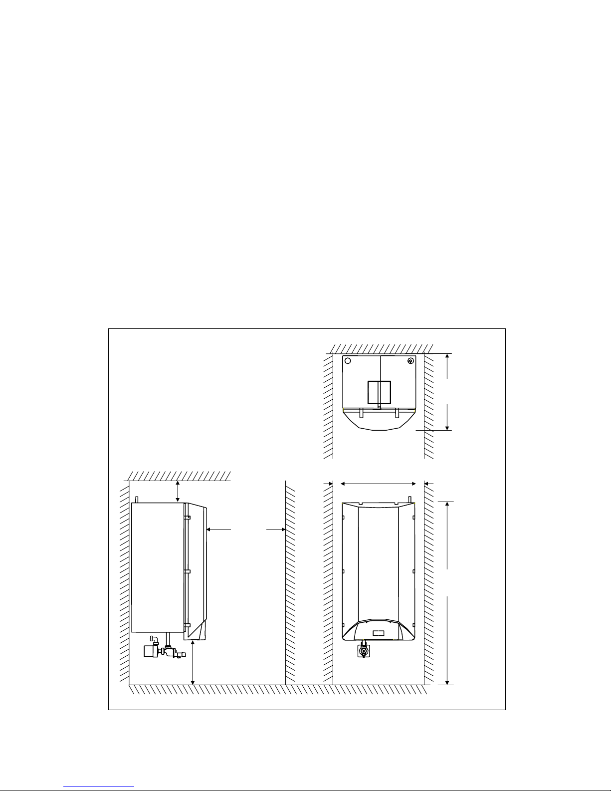
The following clearances are required for maintenance purposes:
Side view Front view
500
m
50mm 50m
m
150mm
510mm
>600mm
1330mm
Top
view
400mm

M 1261-06-X AquaSol Ferroli Installation Manual.doc July 2006 Page 6 of 24
6.2 Mounting Requirements
The unit has a total filled weight of 118 kg, and as such provision must be made for
the mounting wall to accommodate this weight via the wall mounting points. Use the
fixings supplied.
6.3 Positioning and Mounting the System
Once the position of the unit has been determined, the fixing points should be
marked on to the wall at a minimum height of 1300mm from floor level, and at
325mm centres. Holes should be drilled at these points to accept the wall bolts
directly or the supplied plugs, depending on the wall type. Fix the supplied mounting
bracket using the wall bolts, and ensure the bracket is horizontal/level.
Note: if the AquaSol is not mounted on a solid wall, adequate precautions should be
taken to ensure that the fixings are mounted into the battens of the wall and that
these are of sufficient strength to support the unit.
Hang the unit on the wall bolts and secure with the provided nuts. Adjust the support
leg to the correct height.

M 1261-06-X AquaSol Ferroli Installation Manual.doc July 2006 Page 7 of 24
7. Installing the Unit
Installation of this unit should only be carried out by a ‘registered installer’. That is
an installer who has attended a course, or received instruction during their
apprenticeship, on the installation of Unvented Hot Water Systems. All registered
installers should carry an identification card as issued by the Institute of Unvented
Hot Water Systems, the Construction Industry Training Board, or the Institute of
Plumbers.
Schematic layout of water connections for AquaSol and boiler
Collector
AquaSol
Ferroli
Optimax HE
Boiler
HW
Hot
water
T
MV
Mains in
Inlet kit
T
o drain
Water flow-limiter
T
&P valve
CR CW HW
CF = Collector Flow
CR = Collector Return
CW = Cold Water
HW = Hot water
T
undish
CF
Max 4m
Drain-back
level
CW
Drain valve

M 1261-06-X AquaSol Ferroli Installation Manual.doc July 2006 Page 8 of 24
7.1 Before connecting this unit:
• For the installation of a complete Solar system planning permission may be
required especially if the building is located in a conservation area or is a
listed building. These solar thermal systems are classed as a 'permitted
development'. It is however advised to check with the local planning
department prior to installation.
• Ensure that incoming mains pressure is adequate: minimum 1.5 Bar, but
less than 10 Bar. This information may be obtained from the local water
authority, or by conducting a mains pressure & flow test.
• Excessive use of flux can damage this unit, especially the check valves.
Avoid over-use, and ensure that the system and all pipe work is flushed to
BS7593, thus removing all contaminants prior connecting to the AquaSol.
• Ensure that the discharge pipe (tundish) and drain valve are positioned
away from any electrical components.
7.2 Assembling the Pump and filling manifold
Figure 1
Assemble the pump and filling manifold as shown in Figure 1. Do not attach the
expansion relief module at this time, as it is required to be detached for the system
filling process.
Correct pump orientation
 Loading...