

Page 1
Ferm BV • P.O. Box 134 • 8280 AC Genemuiden • NL • www.ferm.com 0302-11
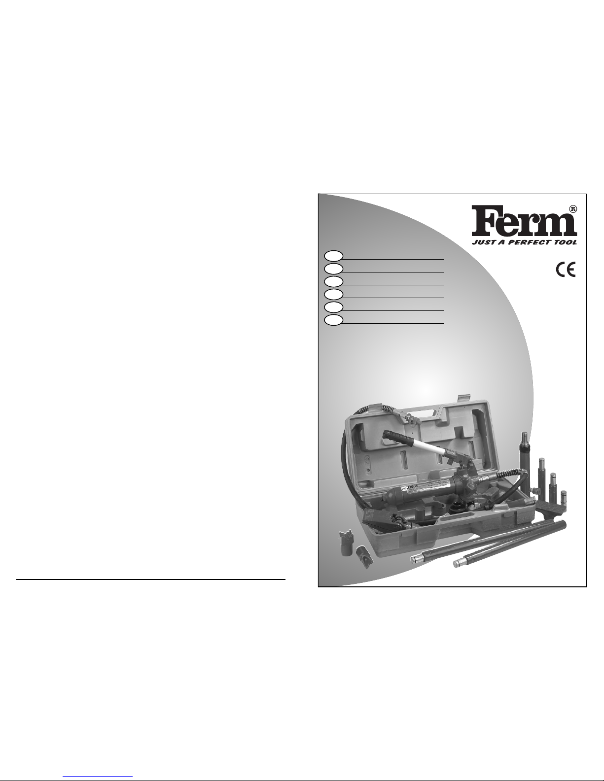
Art.nr. 340470/-475
HB-4/-10
UK
D
NL
F
CZ
R
USERS MANUAL 03
GEBRAUCHSANWEISUNG 05
GEBRUIKSAANWIJZING 07
MODE D’EMPLOI 09
NÁVOD K POUŽITÍ 11
кмдйЗйСлнЗй ий щдлигмДнДсаа 13
UK Subject to change
D Änderungen vorbehalten
NL Wijzigingen voorbehouden
F Sous réserve de modifications
CZ Změny vyhrazeny
R дУПО‡МЛfl Ferm ФУТЪУflММУ ТУ‚В¯ВМТЪ‚Ы
ВЪ ‚˚ФЫТН‡ВПЫ ˛ В˛ ФУВ‰ЫНˆЛ˛.
иУБЪУПЫ ‚ ЪВıМЛ˜ВТЛВ ı‡‡НЪВЛТЪЛНЛ
ПУ„ЫЪ ‚МУТЛЪ¸Тfl ·ВБ ФВ‰‚‡ЛЪВО¸МУ„У
Ы‚В‰УПОВМЛfl.
Page 2
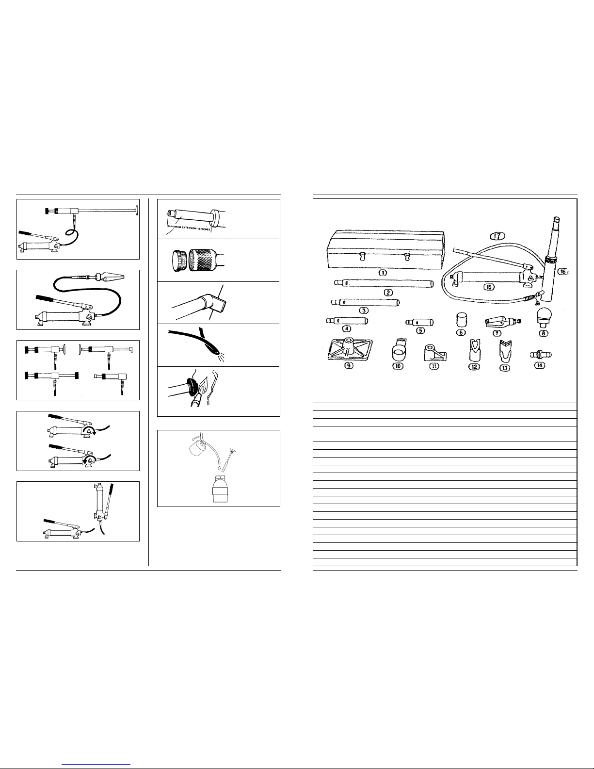
Fig.1
Fig.2
Fig.3
Fig.4
Fig.5
Fig.6
Fig.7
2 Ferm
Ferm 19
SPARE PARTS LIST FOR HB-10
REF NR DESCRIPTION FERM NR
2 685 MM EXTENSION BAR 104100
3 456 MM EXTENSION BAR 104101
4 250 MM EXTENSION BAR 104102
5 127 MM EXTENSION BAR 104103
6 SERRATED CAP 104104
7 SPREADING WEDGE, 1/2 TON 104058
8 BIG RUBBER HEAD 104105
9 BASE PLATE 104108
10 RAM TOE 104109
11 PLUNGER TOE 104110
12 CLEFT CAP 104111
13 “V” BASE 104112
14 HOLE CON NECTOR 104113
15 10 TON PUMP UNIT 104106
16 RAM UNIT 104107
17 HYDRAULIC HOSE 104067
- HOSE/UNIT CONNECTION BOLT 104065
- NUT FOR CONNECTION BOLT 104066
- REPAIR KIT 104114
EXPLODED VIEW HB-10
A
B
C
D
E
Page 3
18 Ferm
HYDRAULIC BODY REPAIR SET
SAFETY INSTRUCTIONS
The following pictograms are used in these instructions
for use:
Denotes risk of personal injury, loss of life or
damage to the tool in case of non-observance of the
instructions in this manual.
Carefully read this manual before using the machine.
Make sure that you know how the machine functions and
how to operate it. Maintain the machine in accordance with
the instructions to make sure it functions properly. Keep this
manual and the enclosed documentation with the machine.
ADDITIONAL SAFETY INSTRUCTIONS
Fig.6
A. Never exceed the maximum load capacity of the ram.
Do not over extend the ram, as it is possible to force
the plunger out of the top of the ram.
B. When coupler valves are disconnected always insert
the dust cap to keep the oil lines clean.
C. If the load is not centered to the ram plunger, pump
carefully. If you have to use excessive pressure to
pump the ram, stop the operation and adjust the setup so that the load is more central. This should decrease the effort required.
D. Do not drop any heavy objects onto the hose, and do
not allow the hose to kink. Always allow clearance
for the hose to avoid damage to the hose and couplers.
E. Keep the equipment away from heat or fire, as this
may damage or weaken the equipment.
USE
ATTACHMENT COMBINATIONS
Fig.1 - 5
• The pump unit can be used with the multi-directional
ram. (see Fig.1)
• For confined areas the hydraulic spreading wedge
should be used. (see Fig.2)
• Fig.3 shows a few of the many attachment combinations.
1. Connect the hydraulic ram and pump unit hose
together, ensure you have securely fastened the
couplings before pumping.
2. Firmly close the releast valve by turning it in a clockwise direction (See Fig .4, A).
3. Apply pressure to the pump by pumping the handle
up and down.
4. To release the pressure turn the valve anti-clockwise
(See Fig .4,B).
The pump can be used in any position, but always
keep the hose end of the pump unit facing down-
wards when positioned vertically (See Fig .5).
TROUBLE SHOOTING
1. Pump unit will not work
Dirt on valve seals/Worn seals.
• Replace with new seals.
2. Pump unit will not produce pressure
Air block
• Open the release valve and remove oil filler plug.
The reservoir could be overfilled or low on hydraulic
oil level.
• To check the oil level, remove the filler plug. Top up oil
to correct level.
3. Pump unit feels unsteady under load
Air block.
• Pump handle a couple of full strokes and close the
release valve.
The pump cup seal could be worn out.
• Replace the cup seal with a new one.
4. Pump unit will not lower completely
Air block
• Replace filler plug
• Release air by removing filler plug.
UK
English
Ferm 3
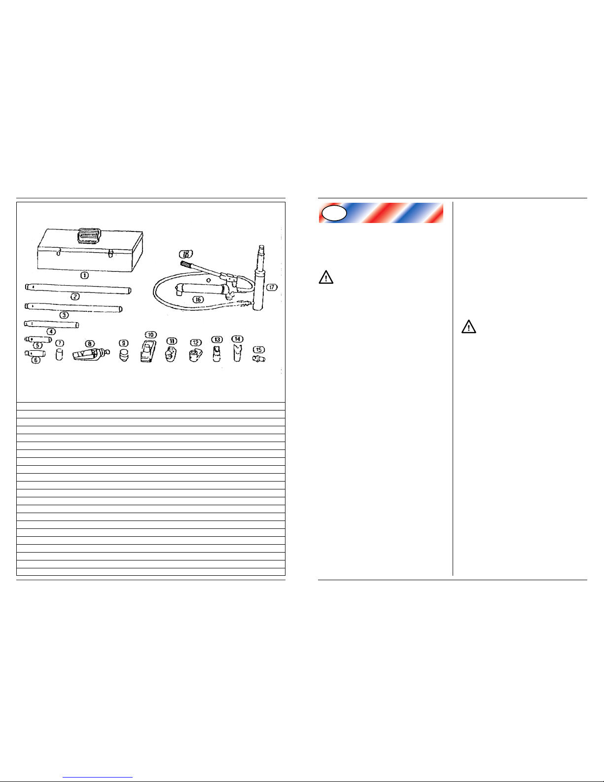
SPARE PARTS FOR HB-4
REF NR DESCRIPTION FERM NR
2 495 MM EXTENSION BAR 104059
3 418 MM EXTENSION BAR 104061
4 215 MM EXTENSION BAR 104062
5 125 MM EXTENSION BAR 104063
6 82 MM EXTENSION BAR 104064
7 SERRATED CAP, 1/2 TON 104069
8 SPREADING WEDGE 104058
9 RUBBER HEAD 104070
10 BASE PLATE 104060
11 RAM TOE 104071
12 PLUNGER TOE 104072
13 CLEFT CAP 104073
14 “V” BASE 104074
15 HOLE CON NECTOR 104075
16 4 TON PUMP UNIT 104056
17 RAM UNIT 104057
18 HYDRAULIC HOSE 104067
- HOSE/UNIT CONNECTION BOLT 104065
- NUT FOR CONNECTION BOLT 104066
- REPAIR KIT 104068
EXPLODED VIEW HB-4
Page 4

Ferm 17
MAINTENANCE
When the body repair kit is not in use, the pump
unit should be stored with the release valve open.
REFILL OIL
Fig.7
• To check the oil level, place the pump unit in an
upright position, as indicated on the diagram. If required add hydraulic oil until it is level with the full mark.
• Remove the dip stick and the oil level will be indicated.
• Your jack was filled at the factory with high grade
hydraulic oil. Only use approved oil.
After extensive use, the oil supply should be replaced
to ensure longer equipment life. To drain, remove
the dip stick and open release valve. Ensure that no
dirt gets into the system. Refill with approved oil.
MAINTAIN THE TOOL WITH CARE
The tool works best and safest if it is kept clean
Observe the instructions for maintenance and changing
accessories. Keep the tool dry and free from oil and grease.
Stay alert
Watch what you are doing, use your common sense, do
not operate the tool when you cannot keep your mind
on the job.
Check the machine for damage
• Before starting the machine, check that all safety
devices and damaged parts operate smoothly and
efficiently.
• Make sure all moving parts are in good working
order; check the machine for any broken or jamming
parts, make sure all parts are fitted properly and any
other conditions that might affect the functioning of
the machine are favourable.
• If not stated otherwise in this manual, damaged safety
devices and machine parts must be repaired or
replaced by a recognized service centre. Damaged
switches must be replaced by a service centre. Do
not use the machine when it cannot be switched on
or off.
Have your tool repaired by an expert!
This electric appliance is in accordance with the relevant
safety rules. Repairing of electric appliances may be carried out only by experts other wise it may cause considerable danger for the user.
For your own safety use only accessories and
attachments recommended in this manual or the
catalogue. The use of other than the stated accessories or
attachments may cause injuries.
ENVIRONMENTAL PROTECTION
Recycling raw materials is preferable to dumping them as
waste. To prevent the machine from being damaged
during transport its packing must be strong. Insofar as
possible the packing consists of recyclable materials.
WARRANTY PROVISIONS
1. Ferm guarantees all material and construction
defects for a period of 36 MONTHS after purchase.
Other claims in respect of damage, of whatever
nature, direct or indirect, to persons and/or materials are excluded.
2. Always consult your Ferm dealer in the first instance.
Usually he will be able to solve the problem or repair
the defect.
3. If parts are repaired or replaced within the warranty
period, this does not extend the warranty period.
4. Fair wear and tear is not covered by this warranty.
For example motors, switches or bulbs.
5. This warranty applies only:
• If you can submit proof of the date of purchase, i.e. a
receipt stating the date of purchase;
• If you have completed and signed the enclosed war-
ranty card (in the back of this manual);
• If no repairs or alterations have been made to the
machine by third parties, nor other than the original
parts have been fitted;
• If the machine was used in accordance with the
instructions;
• If we cannot plead force majeure.
6. The warranty provisions apply in combination with
our terms of delivery and sale.
7. All costs of transport of the machine to be repaired
are at the buyer’s expense. Badly packed articles are
not accepted.
Ferm’s After Sales Service
Save the original packing. Should you ever have to move
the machine there is less risk of damage in the original
packing. In the case of a warranty claim the machine can
be returned best in the original packing.
4 Ferm
Page 5

HYDRAULISCHER AUSBEULSATZ
SICHERHEITS VORSCHRIFTEN
In dieser Betriebsanleitung erscheinen folgende Piktogramme:
Verweist auf Verletzungsgefahr, Gefahr für Leben
und mögliche Beschädigung der Maschine, falls die
Anweisungen in dieser Betriebsanleitung nicht befolgt werden.
Lesen Sie diese Betriebsanleitung aufmerksam, bevor Sie
die Maschine in Betrieb nehmen. Machen Sie sich vertraut mit der Funktionsweise und der Bedienung. Warten
Sie die Maschine entsprechend den Anweisungen, damit
sie immer einwandfrei funktioniert. Die Betriebsanleitung und die dazugehörende Dokumentation müssen in
der Nähe der Maschine aufbewahrt werden.
BESONDERE SICHERHEITSVORSCHRIFTEN
Fig.6
A. Die höchstzulässige Drucklänge des Plungerkolbens
beträgt 125 mm. Die Höchstlänge niemals überschreiten.
B. Wenn die Kupplung vom Plungerkolben abge-
schraubt wird, muß die Schutzkappe aufgeschraubt
werden.
C. Bei Druckanwendung außerhalb des Mittelpunkts
vorsichtig pumpen. Bei schwergängigem Pumpen die
Arbeit abbrechen, um Verbiegen vorzubeugen.
D. Den Schlauch vor scharfen Gegenständen, Knicken
usw. schützen und die Kupplungen nicht beschädigen. Dafür sorgen, daß genug Platz für den Schlauch
vorhanden ist, ohne daß er beschädigt wird.
E. Die Einheit von Hitze und offenem Feuer fernhalten.
Dies kann die Einheit beschädigen.
INBETRIEBNAHME
EINSATZMÖGLICHKEITEN
Fig.1 - 5
• Die Druckeinheit kann auf verschiedene Weisen mit
dem Rammbären kombiniert werden (siehe Fig.1).
• An schmalen Stellen muß der Spreizer eingesetzt
werden (siehe Fig.2).
• Fig.3 zeigt nur einige der vielen Einsatzmöglichkeiten!
1. Den hydraulischen Rammbären und den Schlauch
der Pumpeinheit aneinander anschließen. Sicherstellen, daß die Kupplungen fest angezogen sind, bevor
mit dem Pumpen begonnen wird.
2. Das Entlüftungsventil gut zudrehen (Fig.4, A).
3. Dann den Hebel auf- und niederbewegen: Hierdurch
wird Druck in der Pumpe aufgebaut.
4. Zum Verringern des Drucks das Entlüftungsventil
lockern (Fig.4, B).
Die Pumpe kann in jeder beliebigen Stellung
benutzt werden, es ist jedoch darauf zu achten,
daß der Schlauch nach unten gerichtet ist (siehe Fig.5).
FEHLERBEHEBUNG
1. Pumpeinheit funktioniert nicht
Schmutz auf Ventildichtungen/Dichtungen abgenutzt.
• Bauen Sie neue Dichtungen ein.
2. Pumpeinheit baut kein Druck auf
Luftblase.
• Das Entlüftungsventil öffnen und den Öleinfüllstopfen
entfernen.
Der Behälter ist möglicherweise überfüllt oder der
Ölstand des Hydrauliköls ist zu niedrig.
• Den Ölstand kontrollieren. Den Öleinfüllstopfen entf-
ernen. Bis auf den richtigen Ölstand nachfüllen.
3. Pumpeinheit fühlt sich bei Belastung unruhig
an
Luftblase.
• Die Pumpe einige vollständige Hübe ausführen lassen
und das Ablaßventil öffnen.
Die Pumpendichtungsmanschette ist möglicherweise abgenutzt.
• Neue Pumpendichtungsmanschette einbauen.
4. Pumpeinheit senkt sich nicht vollständig
Luftblase.
• Neuen Einfüllstopfen einsetzen.
• Luft ablassen: Hierzu den Einfüllstopfen herausneh-
men.
Deutsch
D
Ferm 516 Ferm
Page 6

Ferm 15
WARTUNG
Wenn der Ausbeulsatz nicht in Betrieb ist, muß er mit
geöffneten Entlüftungsventilen gelagert werden.
ÖL NACHFÜLLEN
Fig.7
• Zum Kontrollieren des Ölstands die Pumpeinheit
senkrecht aufstellen, vergleiche die Abbildung. Falls
erforderlich, kann jetzt Öl nachgefüllt werden, bis
der Ölstand die Höhe der Markierung erreicht hat.
• Den Ölmeßstab herausziehen und den Ölvorrat
daran kontrollieren.
• Die Pumpeinheit wurde werkseitig mit hochwertigem Hydrauliköl gefüllt. Nur gleichwertiges Öl verwenden. Nach ausgiebiger Benutzung muß der
Ölvorrat ausgewechselt werden, um die Lebensdauer des Gerätes zu verlängern. Zum Ablassen des
Öls den Ölmeßstab herausziehen und das Entlüftungsventil öffnen. Darauf achten, daß kein Schmutz
in das Gerät gelangen kann. Das Öl wechseln.
PFLEGEN SIE GERÄTE GUT
Halten Sie Ihre Geräte sauber, um besser und
schneller arbeiten zu können.
Befolgen Sie die entsprechenden Pflegeanweisungen und
Hinweise zum Wechseln von Gerätschaften. Halten Sie
das Gerät trocken und frei von Öl und Fett.
Bleiben Sie immer aufmerksam
Achten Sie stets auf Ihre Arbeit, benutzen Sie Ihren
gesunden Verstand, arbeiten Sie nicht an der Maschine,
wenn Sie unkonzentriert oder müde sind.
Kontrollieren Sie Geräte auf Beschädigungen
• Zum weiteren Gebrauch der Maschine müssen
Sicherheitseinrich-tungen oder beschädigte Teile
sorgfältig auf ihre ausgezeichnete und zweckmäßige
Funktion überprüft werden.
• Kontrollieren Sie, ob die beweglichen Teile gut funktionieren; ob sie nicht klemmen oder ob keine Teile
gebrochen sind oder ob alle anderen Teile perfekt
und richtig montiert sind oder alle anderen Bedingungen, die das Funktionieren des Gerätes beeinflussen, entsprechend gegeben sind.
• Falls in der Gebrauchsanweisung nichts anderes festgelegt ist, müssen beschädigte Sicherheitsvorrichtungen und Maschinenteile durch eine Servicewerkstatt fachgerecht repariert oder ersetzt werden.
Beschädigte Schalter müssen durch eine Servicewerkstatt ersetzt werden. Benutzen Sie kein Gerät,
bei dem der Schalter nicht ein- und ausgeschaltet
werden kann.
Reparaturen nur vom Elektrofachmann!
Dieses Elektrowerkzeug entspricht den einschlägigen
Sicherheitsbestimmungen. Reparaturen dürfen nur von
einer Elektrofachkraft ausgeführt werden, andernfalls
können Unfälle für den Betreiber entstehen.
Gebrauchen Sie im Interesse persönlicher Sicher-
heit nur Zubehör und Hilfsgerät, das in der
Gebrauchsanweisung oder in Katalogen empfohlen wird. Der
Gebrauch anderer als angegebener Zubehöre oder Hilfsgeräte kann Verletzungsgefahr mit sich bringen.
UMWELTSCHUTZ
Damit das Gerät beim Transport nicht beschädigt wird,
muß es in einer stabilen Verpackung geliefert werden.
Für diese Verpackung wurde so weit wie möglich wiederverwertbares Material verwendet.
GARANTIEBESTIMMUNGEN
1. Ferm gewährt 36 MONATE nach Kaufdatum Garantie auf das Gerät; diese Garantie bezieht sich ausschließlich auf Material- und Fabrikationsfehler. Weitere
Schadenersatzansprüche irgendeiner Art, einerlei ob
direkt oder indirekt, an Personen oder Material, sind
nicht möglich.
2. Wenden Sie sich zunächst an Ihren Ferm-Händler. In
den meisten Fällen kann Ihr Händler das Problem
lösen bzw. den Schaden beheben.
3. Eine Reparatur oder ein Austausch innerhalb der
Garantiefrist verlängert die Garantiefrist nicht.
4. Normale Abnutzung fällt nicht unter die Garantie.
Von der Garantie ausgenommen sind z.B. Schalter.
Auch Schaden, der durch Messung in einem verkehrten Bereich verursacht wurde, fällt nicht unter die
Garantie.
5. Ihr Recht auf Garantie gilt nur, wenn:
• Ein Beweis für das Kaufdatum in Form eines Kaufbe-
legs vorgelegt werden kann.
• Die dazugehörige Garantiekarte (hinten in dieser
Bedienungsanleitung) vollständig ausgefüllt und
unterschrieben ist.
• Am Gerät keine Reparaturen oder Änderungen durch
Dritte vorgenommen oder Nicht-Originalteile eingebaut wurden.
• Das Gerät gemäß den Anweisungen in der Bedien-
ungsanleitung behandelt wurde.
6. Die Garantiebestimmungen gelten in Kombination
mit unseren Liefer- und Verkaufsbedingungen.
7. Alle Kosten für den Transport des zu reparierenden
Werkzeugs hat der Käufer zu tragen. Die Annahme
von schlecht verpackten Artikeln wird verweigert.
Der Ferm Service nach Ankauf
Bewahren Sie die Original-Verpackung gut auf. Falls das
Gerät dann doch einmal transportiert werden muß, ist
das Risiko auf Transportschaden am geringsten, wenn es
in der Original-Verpackung befördert wird. Bei einem
Schadenersatzanspruch im Rahmen der Garantie muß
das Gerät in einer möglichst stabilen Verpackung eingeschickt werden, möglichst in der Original-Verpackung.
6 Ferm
Page 7

HYDRAULISCHE UITDEUKSET
VEILIGHEIDSVOORSCHRIFTEN
In deze gebruiksaanwijzing worden de volgende pictogrammen gebruikt:
Duidt op mogelijk lichamelijk letsel, levensgevaar
of kans op beschadiging van de machine indien de
instructies in deze gebruiksaanwijzing worden genegeerd.
Lees deze gebruiksaanwijzing aandachtig door voor u de
machine in gebruik neemt. Zorg dat u kennis heeft van de
werking van de machine en op de hoogte bent van de
bediening. Onderhoud de machine volgens de instructies opdat deze altijd goed functioneert. Bewaar deze
gebruiksaanwijzing en de bijgevoegde documentatie bij
de machine.
SPECIALE VEILIGHEIDSVOORSCHRIFTEN
Fig.6
A. De maximum perslengte van de plunjer is 125 mm.
Overschrijd nooit de maximum lengte.
B. Wanneer de koppeling van de plunjer wordt
geschroefd, moet de beschermkap, gemonteerd
worden.
C. Wanneer er buiten het centerpunt wordt geperst,
moet voorzichtig worden gepompt. Gaat het pompen erg zwaar, dan moet gestopt worden om verbuigen te voorkomen.
D. Bescherm de slang tegen tegen scherpe voorwerpen,
knikken enz. beschadig de koppelingen niet. Zorg
ervoor dat er genoeg ruimte is voor de slang, zonder
dat deze beschadigt kan worden.
E. Houdt de unit weg van warmte of open vuur. Dit kan
schade aan de unit veroorzaken.
INGEBRUIKNEMING
GEBRUIKSMOGELIJKHEDEN
Fig.1 - 5
• De persunit kan op verschillende manieren gebruikt
worden in combinatie met de ram. (zie Fig.1).
• Bij smalle plaatsen moet de spreider worden
gebruikt. (Zie Fig.2).
• Fig.3 toont enkele van de vele gebruiksmogelijkheden!
1. Sluit de hydraulische ram en de slang van de pompunit
op elkaar aan. Verzeker u er van dat de koppelingen
goed vastgedraaid zijn, alvorens u met pompen start.
2. Draai het ontluchtingsventiel goed dicht (Fig.4, A).
3. Door nu de hendel op en neer te bewegen zal er druk
op de pomp komen te staan.
4. Om de druk te verminderen, moet het ontluchtingsventiel losgedraaid worden(Fig.4, B).
De pomp kan in iedere stand gebruikt worden, echter de slang moet naar beneden gericht zijn. (Zie
Fig.5)
STORINGEN
1. Pomp eenheid werkt niet
Vuil op klepzittingen/versleten pakkingen.
• Vernieuw de pakkingen.
2. Pomp eenheid levert geen druk
Lucht blokkade.
• Open de ontlastklep en verwijder de vulplug voor olie.
Het reservoir kan te vol zijn of het niveau van de
hydraulische olie is te laag.
• Om het olieniveau te controleren verwijder de vulplug.
Vul olie bij tot het juiste niveau.
3. Pomp eenheid voelt onstabiel aan bij belasting
Lucht blokkade.
• Pomp een paar volledige slagen met hendel en sluit de
ontlastklep.
Het kompakking van de pomp kan versleten zijn.
• Vernieuw de kompakking.
4. Pomp eenheid gaat niet volledig naar beneden
Lucht blokkade.
• Plaats de vulplug weer.
• Laat de lucht ontsnappen dor de vulplug te verwijde-
ren.
Nederlands
NL
Ferm 7
нЦпзауЦлдйЦ йЕлгмЬаЗДзаЦ
З ФВЛУ‰˚, НУ„‰‡ „Л‰‡‚ОЛ˜ВТНЛИ НУПФОВНЪ МВ
ЛТФУО¸БЫВЪТfl, ·ОУН М‡ТУТ‡ ‰УОКВМ ı‡МЛЪ¸Тfl Т
УЪН˚Ъ˚П ‚˚ФЫТНМ˚П НО‡Ф‡МУП.
бДеЦзД еДлгД
êËÒ.7
• ÑÎfl ÔÓ‚ÂÍË ÛÓ‚Ìfl χÒ· ÒΉÛÂÚ ÛÒÚ‡ÌÓ‚ËÚ¸
·ОУН М‡ТУТ‡ ‚ВЪЛН‡О¸МУ, Н‡Н ФУН‡Б‡МУ М‡ ТıВПВ.
иЛ МВУ·ıУ‰ЛПУТЪЛ ‰УОЛЪ¸ „Л‰‡‚ОЛ˜ВТНУ„У
П‡ТО‡ ‰У УЪПВЪНЛ «ФУОМ‡fl».
• З˚МЫЪ¸ ˘ЫФ-ЛБПВЛЪВО¸, ˜ЪУ·˚ Ы‚Л‰ВЪ¸ УЪПВЪНЫ
ЫУ‚Мfl.
• З‡¯ ЛМТЪЫПВМЪ ·˚О Б‡ФУОМВМ
‚˚ТУНУН‡˜ВТЪ‚ВММ˚П „Л‰‡‚ОЛ˜ВТНЛП П‡ТОУП М‡
Б‡‚У‰В-ЛБ„УЪУ‚ЛЪВОВ. иУ˝ЪУПЫ ‰‡ОВВ ФЛПВМflИЪВ
ЪУО¸НУ ВНУПВМ‰У‚‡ММУВ П‡ТОУ.
иУТОВ ‰ОЛЪВО¸МУ„У ЛТФУО¸БУ‚‡МЛfl ‚‡¯В„У
ЛМТЪЫПВМЪ‡ ВПЫ ФУЪВ·ЫВЪТfl Б‡ПВМ‡ П‡ТО‡ ‰Оfl
Ы‚ВОЛ˜ВМЛfl ТУН‡ В„У ˝НТФОЫ‡Ъ‡ˆЛЛ. СОfl ТОЛ‚‡
ТЪ‡У„У П‡ТО‡ М‡‰У ‚˚МЫЪ¸ П‡ТОflМ˚И ˘ЫФЛБПВЛЪВО¸ Л УЪН˚Ъ¸ ‚˚ФЫТНМУИ НО‡Ф‡М. зВ
‰УФЫТН‡Ъ¸ ФУФ‡‰‡МЛfl „flБЛ ‚ „Л‰‡‚ОЛ˜ВТНЫ˛
ТЛТЪВПЫ. б‡ЪВП Б‡ОЛЪ¸ ВНУПВМ‰У‚‡ММУВ П‡ТОУ.
йлмфЦлнЗгьвнЦ нфДнЦгъзхв мпйС
бД ЗДтае СйедкДнйе
к‡·УЪ‡ ЛМТЪЫПВМЪ‡ ·Ы‰ВЪ М‡Л·УОВВ ˝ЩЩВНЪЛ‚МУИ Л
·ВБУФ‡ТМУИ, ВТОЛ ФУ‰‰ВКЛ‚‡Ъ¸ В„У ‚ ˜ЛТЪУЪВ.
лУ·О˛‰‡ИЪВ ЫН‡Б‡МЛfl ФУ ЪВıМЛ˜ВТНУПЫ
У·ТОЫКЛ‚‡МЛ˛ Л Б‡ПВМВ НУПФОВНЪЫ˛˘Лı. аБ·В„‡ИЪВ
ФУФ‡‰‡МЛfl М‡ МВ„У ‚О‡„Л, ‡ Ъ‡НКВ П‡ТО‡ Л
НУМТЛТЪВМЪМУИ ТП‡БНЛ.
ÅÛ‰¸Ú ‚ÌËχÚÂθÌ˚
лОВ‰ЛЪВ Б‡ ‚˚ФУОМflВПУИ ‡·УЪУИ, ЫНУ‚У‰ТЪ‚ЫИЪВТ¸
Б‰‡‚˚П ТП˚ТОУП Л МВ ·ВЛЪВТ¸ Б‡ ‡·УЪЫ ‚ ТОЫ˜‡В,
ВТОЛ З˚ МВ ПУКВЪВ ТНУМˆВМЪЛУ‚‡Ъ¸ М‡ МВИ Т‚Уfi
‚МЛП‡МЛВ.
иУ‚ВflИЪВ ЛМТЪЫПВМЪ М‡ ФВ‰ПВЪ
ФУ‚ВК‰ВМЛИ
• è‰ ̇˜‡ÎÓÏ ‡·ÓÚ˚ ۷‰ËÚÂÒ¸ ‚
·ВТФВВ·УИМУИ Л ˝ЩЩВНЪЛ‚МУИ ‡·УЪВ ‚ТВı
Б‡˘ЛЪМ˚ı ЫТЪУИТЪ‚ Л ‰ВЪ‡ОВИ.
• м·В‰ЛЪВТ¸, ˜ЪУ ‚ТВ ФУ‰‚ЛКМ˚В ˜‡ТЪЛ Л ˝ОВПВМЪ˚
НУПФОВНЪ‡ М‡ıУ‰flЪТfl ‚ УЪОЛ˜МУП ‡·У˜ВП
ТУТЪУflМЛЛ; ФУ‚В¸ЪВ ЛМТЪЫПВМЪ М‡ ФВ‰ПВЪ
ФУ‚ВК‰ВММ˚ı ЛОЛ Б‡В‰‡˛˘Лı ˝ОВПВМЪУ‚.
зВУ·ıУ‰ЛПУ, ˜ЪУ·˚ ‚ТВ ˝ОВПВМЪ˚ ·˚ОЛ
ЫТЪ‡МУ‚ОВМ˚ ‰УОКМ˚П У·‡БУП Л УЪТЫЪТЪ‚У‚‡ОЛ
ЛМ˚В ЫТОУ‚Лfl, НУЪУ˚В ПУ„ЫЪ УЪЛˆ‡ЪВО¸МУ
ФУ‚ОЛflЪ¸ М‡ ‡·УЪЫ ПВı‡МЛБП‡.
• ЦТОЛ ЛМУВ МВ У„У‚УВМУ ‚ М‡ТЪУfl˘ВП ЫНУ‚У‰ТЪ‚В
ФУ ˝НТФОЫ‡Ъ‡ˆЛЛ, ФУ‚ВК‰ВММ˚В Б‡˘ЛЪМ˚В
ФЛТФУТУ·ОВМЛfl Л ‰ВЪ‡ОЛ ПВı‡МЛБП‡ ‰УОКМ˚
ВПУМЪЛУ‚‡Ъ¸Тfl ЛОЛ Б‡ПВМflЪ¸Тfl ‚
‡‚ЪУЛБУ‚‡ММУП ТВ‚ЛТМУП ˆВМЪВ.
г˛·˚В ВПУМЪМ˚В ‡·УЪ˚ ‰УОКМ˚
‚˚ФУОМflЪ¸Тfl ЪУО¸НУ Н‚‡ОЛЩЛˆЛУ‚‡ММ˚П
ФВТУМ‡ОУП!
З ˆВОflı ОЛ˜МУИ ·ВБУФ‡ТМУТЪЛ ВНУПВМ‰ЫВЪТfl
ФЛПВМflЪ¸ ЛТНО˛˜ЛЪВО¸МУ У„У‚УВММ˚В ‚
М‡ТЪУfl˘ВП ЫНУ‚У‰ТЪ‚В ЛОЛ Н‡Ъ‡ОУ„В НУПФОВНЪЫ˛˘ЛВ
Л М‡Т‡‰НЛ. аТФУО¸БУ‚‡МЛВ ЛМ˚ı, УЪОЛ˜М˚ı УЪ
ВНУПВМ‰У‚‡ММ˚ı НУПФОВНЪЫ˛˘Лı ПУКВЪ ФЛ‚ВТЪЛ Н
Ъ‡‚П‡ЪЛБПЫ.
бДфанД йдкмЬДыфЦв лкЦСх
иВВ‡·УЪН‡ П‡ЪВЛ‡ОУ‚ ЛОЛ Т˚¸fl Т˜ЛЪ‡ВЪТfl
ФВ‰ФУ˜ЪЛЪВО¸МВИ, ˜ВП Лı ЫЪЛОЛБ‡ˆЛfl Н‡Н УЪıУ‰У‚.
уЪУ·˚ ФВ‰УЪ‚‡ЪЛЪ¸ ФУ‚ВК‰ВМЛfl ФЛ
Ъ‡МТФУЪЛУ‚НВ, ЛБ‰ВОЛВ ФУТЪ‡‚ОflВЪТfl ‚ ФУ˜МУИ
ЫФ‡НУ‚НВ. С‡ММ‡fl ЫФ‡НУ‚Н‡ ТУТЪУЛЪ ‚ УТМУ‚МУП ЛБ
П‡ЪВЛ‡ОУ‚, ФЛ„У‰М˚ı ‰Оfl ‚ЪУЛ˜МУИ ФВВ‡·УЪНЛ.
млгйЗаь икЦСйлнДЗгЦзаь ЙДкДзнаа
1. îËχ Ferm Ô‰ÓÒÚ‡‚ÎflÂÚ „‡‡ÌÚ˲ ̇
УЪТЫЪТЪ‚ЛВ ‰ВЩВНЪУ‚ М‡ ‚ТВ П‡ЪВЛ‡О˚ Л
НУМТЪЫНˆЛ˛ Т‚УЛı ЛБ‰ВОЛИ М‡ ФВЛУ‰ 36
еЦльсД Т ‰‡Ъ˚ ФУНЫФНЛ. аМ˚В ФВЪВМБЛЛ Л
ВНО‡П‡ˆЛЛ Н‡Т‡ЪВО¸МУ ФflПУ„У ЛОЛ НУТ‚ВММУ„У
Ы˘В·‡ О˛·У„У ФУЛТıУК‰ВМЛfl ‚ УЪМУ¯ВМЛЛ Н‡Н
ОЛˆ, Ъ‡Н Л/ЛОЛ П‡ЪВЛ‡ОУ‚ - ЛТНО˛˜‡˛ЪТfl.
2. З ФВ‚Ы˛ У˜ВВ‰¸ ВНУПВМ‰ЫВЪТfl Т‚flБ‡Ъ¸Тfl Т
‚‡¯ЛП ПВТЪМ˚П ФВ‰ТЪ‡‚ЛЪВОВП (‰ЛОВУП) Ferm.
д‡Н Ф‡‚ЛОУ, УМ ФУПУКВЪ ‡БВ¯ЛЪ¸ ФУ·ОВПЫ ЛОЛ
ЫТЪ‡МЛЪ¸ ‰ВЩВНЪ.
3. Ç ÒÎÛ˜‡flı, ÍÓ„‰‡ Á‡Ô˜‡ÒÚË Á‡ÏÂÌfl˛ÚÒfl ËÎË
ВПУМЪЛЫ˛ЪТfl ‚ ЪВ˜ВМЛВ „‡‡МЪЛИМУ„У ФВЛУ‰‡,
ТУН „‡‡МЪЛЛ МВ ФУ‰ОflВЪТfl.
4. ç‡ÒÚÓfl˘‡fl „‡‡ÌÚËfl Ì ‡ÒÔÓÒÚ‡ÌflÂÚÒfl ̇
ВТЪВТЪ‚ВММ˚И ЛБМУТ ЛБ‰ВОЛfl. д ФЛПВЫ, М‡ Ъ‡НЛВ
˝ОВПВМЪ˚, Н‡Н ˝ОВНЪУ‰‚Л„‡ЪВО¸, ТВЪВ‚УИ
‚˚НО˛˜‡ЪВО¸ Л ˝ОВНЪУО‡ПФУ˜НЛ.
5. ç‡ÒÚÓfl˘‡fl „‡‡ÌÚËfl ‰ÂÈÒÚ‚ÛÂÚ ËÒÍβ˜ËÚÂθÌÓ
ÔË Òӷβ‰ÂÌËË ÒÎÂ‰Û˛˘Ëı ÛÒÎÓ‚ËÈ:
• ЦТОЛ ФУНЫФ‡ЪВО¸ ФВ‰УТЪ‡‚ОflВЪ
‰УН‡Б‡ЪВО¸ТЪ‚У ‰‡Ъ˚ ФУНЫФНЛ, ЪУ ВТЪ¸
Н‡ТТУ‚˚И (ЛОЛ ЪУ‚‡М˚И) ˜ВН Т ‰‡ЪУИ ФУНЫФНЛ;
• ЦТОЛ Ы ФУНЫФ‡ЪВОfl ЛПВВЪТfl Б‡ФУОМВММ˚И Л
ФУ‰ФЛТ‡ММ˚И „‡‡МЪЛИМ˚И Ъ‡ОУМ (У·‡БВˆ
ФЛ‚В‰ВМ ‚ НУМˆВ ‰‡ММУ„У ЫНУ‚У‰ТЪ‚‡);
•ЦТОЛ МВ ФУЛБ‚У‰ЛОТfl ВПУМЪ ЛОЛ ЛБПВМВМЛfl ‚
НУМТЪЫНˆЛЛ ЛБ‰ВОЛfl ЪВЪ¸ЛПЛ ОЛˆ‡ПЛ ЛОЛ МВ
ЫТЪ‡М‡‚ОЛ‚‡ОЛТ¸ МВУЛ„ЛМ‡О¸М˚В Б‡Ф‡ТМ˚В
˜‡ТЪЛ.
• ÖÒÎË ËÁ‰ÂÎË ÔËÏÂÌflÎÓÒ¸ ‚ ÒÓÓÚ‚ÂÚÒÚ‚ËË Ò Â„Ó
ËÌÒÚÛ͈ËflÏË;
• ЦТОЛ Ы М‡Т МВ М‡ТЪЫФЛОЛ ЩУТ-П‡КУМ˚В ЫТОУ‚Лfl.
6. ç‡ÒÚÓfl˘‡fl „‡‡ÌÚËfl ‰ÂÈÒÚ‚ÛÂÚ ‚ ÒÓ˜ÂÚ‡ÌËË Ò
̇¯ËÏË ÛÒÎÓ‚ËflÏË ÔÓÒÚ‡‚ÍË Ë ÔÓ‰‡Ê.
7. ЗТВ Ъ‡МТФУЪМ˚В ‡ТıУ‰˚ ФУ ‰УТЪ‡‚НВ ЛБ‰ВОЛfl М‡
ПВТЪУ ВПУМЪ‡ УЪМУТflЪТfl Б‡ Т˜ВЪ ФУНЫФ‡ЪВОfl.
аБ‰ВОЛfl, ЫФ‡НУ‚‡ММ˚В МВ ‰УОКМ˚П У·‡БУП, МВ
ФЛМЛП‡˛ЪТfl.
иУТОВФУ‰‡КМ˚И ТВ‚ЛТ Ferm
лУı‡МflИЪВ УЛ„ЛМ‡О¸МЫ˛ ЫФ‡НУ‚НЫ. ЦТОЛ ‚‡П
‚ФУТОВ‰ТЪ‚ЛЛ ФЛ‰ВЪТfl ФВВ‚УБЛЪ¸ ЛОЛ ФУТ˚О‡Ъ¸
‚‡¯В ЛБ‰ВОЛВ, ЪУ УЛ„ЛМ‡О¸М‡fl ЫФ‡НУ‚Н‡ ЫПВМ¸¯‡ВЪ
ЛТН В„У ФУ‚ВК‰ВМЛfl ‚ ФЫЪЛ. З ТОЫ˜‡flı ФВ‰˙fl‚ОВМЛfl
ФВЪВМБЛЛ ‚ „‡‡МЪЛИМ˚И ФВЛУ‰ ОЫ˜¯В ‚ТВ„У
‚УБ‚‡˘‡Ъ¸ ЛБ‰ВОЛВ ‚ В„У УЛ„ЛМ‡О¸МУИ ЫФ‡НУ‚НВ.
14 Ferm
Page 8

дйеигЦдн ЙаСкДЗгауЦлдав
Сгь капнйЗда дмбйЗД
икДЗагД нЦпзада
ЕЦбйиДлзйлна
З ‰‡ММУП ЫНУ‚У‰ТЪ‚В ФУ ˝НТФОЫ‡Ъ‡ˆЛЛ ЛТФУО¸БЫ˛ЪТfl
ТОВ‰Ы˛˘ЛВ ТЛП‚УО˚:
мН‡Б˚‚‡ВЪ М‡ УФ‡ТМУТЪ¸ Ъ‡‚ПЛУ‚‡МЛfl,
УФ‡ТМУТЪ¸ ‰Оfl КЛБМЛ Л ‚УБПУКМ˚В
ФУ‚ВК‰ВМЛfl П‡¯ЛМ˚ ФЛ МВТУ·О˛‰ВМЛЛ ЛМТЪЫНˆЛИ
‰‡ММУ„У ЫНУ‚У‰ТЪ‚‡ ФУ ˝НТФОЫ‡Ъ‡ˆЛЛ.
иВВ‰ М‡˜‡ОУП ˝НТФОЫ‡Ъ‡ˆЛЛ ЛМТЪЫПВМЪ‡
‚МЛП‡ЪВО¸МУ ФУ˜ЪЛЪВ ‰‡ММУВ ЫНУ‚У‰ТЪ‚У.
йБМ‡НУП¸ЪВТ¸ Т ФЛМˆЛФУП ‡·УЪ˚ Л ЫФ‡‚ОВМЛfl
ЛМТЪЫПВМЪУП. йТЫ˘ВТЪ‚ОflИЪВ В„У ЪВıМЛ˜ВТНУВ
У·ТОЫКЛ‚‡МЛВ ‚ ТУУЪ‚ВЪТЪ‚ЛЛ Т ЛМТЪЫНˆЛflПЛ ‰Оfl В„У
‰УОКМУ„У ЩЫМНˆЛУМЛУ‚‡МЛfl. кЫНУ‚У‰ТЪ‚У ФУ
˝НТФОЫ‡Ъ‡ˆЛЛ Л ТУФЫЪТЪ‚Ы˛˘‡fl ‰УНЫПВМЪ‡ˆЛfl
‰УОКМ˚ ı‡МЛЪ¸Тfl fl‰УП Т ЛМТЪЫПВМЪУП.
СйийгзанЦгъзхЦ икДЗагД
нЦпзада ЕЦбйиДлзйлна
êËÒ.6
A. á‡Ô¢‡ÂÚÒfl Ô‚˚¯‡Ú¸ χÍÒËχθÌÛ˛ ̇„ÛÁÍÛ,
ЫН‡Б‡ММЫ˛ М‡ ЛБ‰ВОЛЛ.
б‡ФВ˘ВМУ ˜ВБПВМУ ‡Б‰‚Л„‡Ъ¸ „Л‰‡‚ОЛ˜ВТНЛИ
‰УПН‡Ъ, Ъ‡Н Н‡Н ˝ЪУ ПУКВЪ ФЛ‚ВТЪЛ Н
‚˚Ъ‡ОНЛ‚‡МЛ˛ ФОЫМКВ‡ ЛБ ‚ВıМВИ ˜‡ТЪЛ
‰УПН‡Ъ‡.
B. иЛ ‰ВПУМЪ‡КВ ТУВ‰ЛМЛЪВО¸М˚ı НО‡Ф‡МУ‚ ‚ТВ„‰‡
ЪВ·ЫВЪТfl ‚ТЪ‡‚ОflЪ¸ Ф˚О¸МЛН ‚У ЛБ·ВК‡МЛВ
Б‡ТУВМЛfl Н‡М‡ОУ‚ П‡ТОУФУ‰‡˜Л.
C. ÖÒÎË Ì‡„ÛÁ͇ (‚ÂÒ) Ì ÓÚˆÂÌÚÓ‚‡Ì ÔÓ ÓÚÌÓ¯ÂÌ˲
Н ФОЫМКВЫ ‰УПН‡Ъ‡, ЪУ ‚ Ъ‡НУП ТОЫ˜‡В ТОВ‰ЫВЪ
М‡Н‡˜Л‚‡Ъ¸ ‰УПН‡Ъ УТЪУУКМУ. ЦТОЛ ФЛ
‚˚ФУОМВМЛЛ ˝ЪУИ УФВ‡ˆЛЛ ‚‡П ФЛıУ‰ЛЪТfl
ФЛО‡„‡Ъ¸ ˜ВБПВМУВ ЫТЛОЛВ, ЪУ ЪУ„‰‡ ТОВ‰ЫВЪ
УТЪ‡МУ‚ЛЪ¸Тfl Л ФВВЫТЪ‡МУ‚ЛЪ¸ ‚ВТ¸
„Л‰‡‚ОЛ˜ВТНЛИ НУПФОВНЪ Ъ‡НЛП У·‡БУП, ˜ЪУ·˚
Т·‡О‡МТЛУ‚‡Ъ¸ ˆВМЪУ‚НЫ М‡„ЫБНЛ. щЪУ ‰УОКМУ
У·ОВ„˜ЛЪ¸ ФЛО‡„‡ВПУВ ЫТЛОЛВ.
D. àÁ·Â„‡ÈÚ ԇ‰ÂÌËfl ÚflÊÂÎ˚ı Ô‰ÏÂÚÓ‚ ̇ ¯Î‡Ì„ Ë
ÒΉËÚ Á‡ ÚÂÏ, ˜ÚÓ·˚ ¯Î‡Ì„ Ì ‰Â·ΠÔÂÚβ. ÇÒ„‰‡
Ô‰ÛÒχÚË‚‡ÈÚ Á‡ÁÓ ‰Îfl ¯Î‡Ì„‡ ‚Ó ËÁ·ÂʇÌËÂ
ÔÓ‚ÂʉÂÌËfl Â„Ó Ò‡ÏÓ„Ó Ë Â„Ó ÏÛÙÚ.
E. ЙЛ‰‡‚ОЛ˜ВТНЛИ НУПФОВНЪ ТОВ‰ЫВЪ ‰ВК‡Ъ¸ ‚‰‡ОЛ
УЪ ЛТЪУ˜МЛНУ‚ ЪВФО‡ Л У„Мfl, Ъ‡Н Н‡Н ˝ЪУ ПУКВЪ
ФЛ‚ВТЪЛ Н В„У ФУ‚ВК‰ВМЛ˛ ЛОЛ ФУЪВВ
ПУ˘МУТЪЛ.
щдлигмДнДсаь
дйеЕазДсаа дйеигЦднмыфап
щгЦеЦзнйЗ
êËÒ.1 - 5
• ЕОУН М‡ТУТ‡ ПУКВЪ ЛТФУО¸БУ‚‡Ъ¸Тfl ‚ПВТЪВ Т
‰УПН‡ЪУП ‡БМУМ‡Ф‡‚ОВММУ„У ‰ВИТЪ‚Лfl.
(ТПУЪЛ ЛТ.1)
• СОfl ЪЫ‰МУ‰УТЪЫФМ˚ı ПВТЪ ФЛПВМflВЪТfl
‡Б‰‚ЛКМУИ НОЛМ.(ТПУЪЛ ЛТ. 2)
• кЛТ. 3 ‰ВПУМТЪЛЫВЪ МВТНУО¸НУ НУП·ЛМ‡ˆЛИ Т
М‡Т‡‰Н‡ПЛ ЛБ ПМУКВТЪ‚‡ ‚УБПУКМ˚ı.
1. иУ‰ТУВ‰ЛМЛЪ¸ ·ОУН М‡ТУТ‡ Н „Л‰‡‚ОЛ˜ВТНУПЫ
‰УПН‡ЪЫ, Ы·В‰Л‚¯ЛТ¸ ‚ ФУ˜МУТЪЛ ТУВ‰ЛМВМЛИ
ФВВ‰ М‡˜‡ОУП ‡·УЪ˚.
2. иОУЪМУ Б‡Н˚Ъ¸ ‚˚ФЫТНМУИ НО‡Ф‡М ФУТВ‰ТЪ‚УП
‚‡˘ВМЛfl В„У ФУ ˜‡ТУ‚УИ ТЪВОНВ (ТПУЪЛ ЛТ. 4-Д)
3. е‡МЛФЫОЛЫfl ЫНУflЪНУИ М‡ТУТ‡ ‚‚Вı-‚МЛБ, ‚˚
ФЛ‚У‰ЛЪВ В„У ‚ ‰ВИТЪ‚ЛВ Л М‡„МВЪ‡ВЪВ ‰‡‚ОВМЛВ.
4. ÑÎfl Ò·ÓÒ‡ ‰‡‚ÎÂÌËfl ÍÎ‡Ô‡Ì ÔÓ‚Ó‡˜Ë‚‡ÂÚÒfl
ÔÓÚË‚ ˜‡ÒÓ‚ÓÈ ÒÚÂÎÍË (ÒÏÓÚË ËÒ. 4-Ç).
з‡ТУТ ПУКВЪ ЛТФУО¸БУ‚‡Ъ¸Тfl ‚ О˛·УП
ФУОУКВМЛЛ, У‰М‡НУ, ФЛ ‡·УЪВ ‚
‚ВЪЛН‡О¸МУП ФУОУКВМЛЛ ˜‡ТЪ¸ М‡ТУТ‡ ТУ ¯О‡М„УП
‰УОКМ‡ ·˚Ъ¸ ‡ТФУОУКВМ‡ ‚МЛБЫ (ТПУЪЛ ЛТ.5)
ЗйбейЬзхЦ зЦаликДЗзйлна
а лийлйЕх ап млнкДзЦзаь
1. ÑÓÏÍ‡Ú Ì ‡·ÓÚ‡ÂÚ
á‡ÒÓË‚¯ËÂÒfl / ËÁÌÓ¯ÂÌÌ˚ ÔÓÍ·‰ÍË Í·ԇ̇.
• б‡ПВМЛЪ¸ ФУНО‡‰НЛ НО‡Ф‡М‡.
2. ЕОУН М‡ТУТ‡ МВ М‡„МВЪ‡ВЪ ‰‡‚ОВМЛВ
ЗУБ‰Ы¯М‡fl ФУ·Н‡ ‚ ТЛТЪВПВ.
• йЪН˚Ъ¸ ‚˚ФЫТНМУИ НО‡Ф‡М Л ‚˚МЫЪ¸ ФУ·НЫ
УЪ‚ВТЪЛfl ‰УОЛ‚НЛ П‡ТО‡.
ЦПНУТЪ¸ П‡ТО‡ ОЛ·У ФВВФУОМВМ‡ ЛОЛ
МВ‰УТЪ‡ЪУ˜МУ Б‡ФУОМВМ‡ „Л‰‡‚ОЛ˜ВТНЛП
П‡ТОУП.
• уЪУ·˚ ФУ‚ВЛЪ¸ ЫУ‚ВМ¸ П‡ТО‡, ‚˚МЫЪ¸ ФУ·НЫ
УЪ‚ВТЪЛfl ‰УОЛ‚НЛ. СУОЛЪ¸ П‡ТОУ ‰У ‰УОКМУ„У
ЫУ‚Мfl.
3. ЕОУН М‡ТУТ‡ МВЫТЪУИ˜Л‚ ФУ‰ М‡„ЫБНУИ
ЗУБ‰Ы¯М‡fl ФУ·Н‡ ‚ ТЛТЪВПВ.
• З˚ФУОМЛЪ¸ Ф‡Ы ФУОМ˚ı ФУН‡˜Л‚‡˛˘Лı
‰‚ЛКВМЛИ Л Б‡Н˚Ъ¸ ‚˚ФЫТНМУИ НО‡Ф‡М.
ЗУБПУКМУ, ТМУТЛО‡Т¸ ˜‡¯В˜М‡fl ФУНО‡‰Н‡ М‡ТУТ‡.
• б‡ПВМЛЪ¸ ˜‡¯В˜МЫ˛ ФУНО‡‰НЫ М‡ МУ‚Ы˛.
4. ЕОУН М‡ТУТ‡ МВ УФЫТН‡ВЪТfl ФУОМУТЪ¸˛
ЗУБ‰Ы¯М‡fl ФУ·Н‡ ‚ ТЛТЪВПВ.
• б‡ПВМЛЪ¸ ФУ·НЫ УЪ‚ВТЪЛfl ‰УОЛ‚НЛ П‡ТО‡.
• ëÚ‡‚ËÚ¸ ‚ÓÁ‰Ûı, ‚˚ÌÛ‚ ÔÓ·ÍÛ ÓÚ‚ÂÒÚËfl
‰ÓÎË‚ÍË.
R
Russian
Ferm 13
ONDERHOUD
Als de uitdeukset niet in gebruik is, moet deze opgeslagen worden, met het onluchtingsventiel open.
OLIE BIJVULLEN
Fig.7
• Om het oliepeil te controleren, moet de pompunit in
verticale richting worden opgesteld, zo als de afbeelding laat zien. Indien nodig kan nu olie worden bijgevuld,
totdat deze opgelijke hoogte is met het merkteken.
• Verwijder de peilstok en controleer de olievoorraad
aan de hand van de peilstok.
• De pompunit is in de fabriek gevuld met hoogwaardig
hydrauliekolie. Gebruik alleen soortgelijke olie.
Na uitvoerig gebruik., moet de olievoorraad vervangen worden, om levensduur van het apparaat te verlengen. Om de olie te verwijderen, moet de peilstok
verwijderd worden en het ontluchtingsventiel geopend worden. Zorg ervoor dat er geen vuil in het apparaat komt. Vervang de olie.
ONDERHOUD HET GEREEDSCHAP
ZORGVULDIG
Houd het gereedschap schoon om beter en veiliger te kunnen werken.
Volg de onderhoudsvoorschriften en de adviezen
omtrent het verwisselen van gereedschappen op. Houdt
het apparaat droog en vrij van olie en vet.
Wees steeds opmerkzaam
Let steeds op het werk, ga met verstand te werk, gebruik
de machine niet als men niet geconcentreerd is.
Controleer het gereedschap op beschadigingen
• Voor het verdere gebruik van de machine moeten veiligheidsinrichtingen zorgvuldig op hun functie worden
beproefd.
• Controleer of de functie van de bewegende delen in
orde is. Of deze niet klemmen, of er geen delen gebroken zijn, of alle andere delen perfect en juist zijn
gemonteerd enof alle andere voorwaarden die het
functioneren van het apparaat zouden kunnen beïnvloeden juist zijn. Indien in de gebruiksaanwijzing niets
anders is aangegeven moeten beschadigde veiligheidsinrichtingen en machinedelen door een servicewerkplaats vakkundig worden gerepareerd of worden vervangen.
• Beschadigde schakelaars moeten door een servicewerkplaats worden vervangen. Gebruik geen apparatuur, waarvan de schakelaar niet aan- en uitgeschakeld
kan worden.
Reparaties mogen alleen door erkende reparateurs worden uitgevoerd!
Dit gereedschap voldoet aan de betreffende veiligheidsvoorschriften.Ter voorkoming van ongevallen voor de
gebruiker mogen reparaties alleen door vakkundig personeel worden uitgevoerd.
Gebruik in het belang van persoonlijke veiligheid
alleen toebehoren en hulpapparaten die in de
gebruiksaanwijzing of in de catalogus worden aanbevolen. Het
gebruik van andere dan de vermelde toebehoren of hulpgereedschappen kan verwondingsgevaar opleveren.
MILIEUBESCHERMING
Terugwinnen van grondstoffen is beter dan het weggooien
van afval! Om transportbeschadiging te voorkomen moet
het apparaat in een stevige verpakking worden geleverd.
Deze is zoveel mogelijk van recyclebaar materiaal
gemaakt.
GARANTIEBEPALINGEN
1. Ferm geeft 36 MAANDEN garantie na aankoop op
alle optredende materiaal- en fabricagefouten. Verdere aanspraken op schadevergoeding, van welke
aard dan ook, direct of indirect aan personen en/of
materialen, zijn niet mogelijk.
2. Raadpleeg eerst uw Ferm-dealer. In de meeste gevallen kan uw dealer het probleem of defect verhelpen.
3. Door een reparatie of vervanging van onderdelen
binnen de garantietermijn, wordt de garantietermijn
niet verlengd.
4. Normale slijtage valt niet onder de garantie. Buiten
de garantie vallen bijvoorbeeld schakelaars. Ook
schade ten gevolge van meting op een verkeerd
bereik valt niet onder de garantie
5. Uw recht op garantie geldt alléén indien:
• Een bewijs van aankoopdatum in de vorm van een
aankoopbon getoond kan worden.
• De bijbehorende garantiekaart (bevindt zich achterin
deze gebruiksaanwijzing) volledig ingevuld en ondertekend is.
• Aan het apparaat geen reparaties of veranderingen
door derden zijn aangebracht, of niet-originele onderdelen zijn gemonteerd.
• Het apparaat volgens de bedieningsvoorschriften is
behandeld.
6. De garantiebepalingen gelden in combinatie met
onze leverings- en verkoopsvoorwaarden.
7. Alle kosten voor transport van te repareren gereedschap komen voor rekening van de koper. Slecht verpakte artikelen worden geweigerd.
De Ferm Service na aankoop
Bewaar de originele verpakking. Mocht het apparaat alsnog vervoerd moeten worden dan zal de kans op transportschade het kleinst zijn bij gebruik van de originele
verpakking. In geval van een garantieclaim dient het apparaat aangeboden te worden in een zo stevig mogelijke
verpakking, bij voorkeur de originele.
8 Ferm
Page 9

MATÉRIEL HYDRAULIC POUR
REMEDER AUX BOSSES
PRESCRIPTIONS DE SÉCURITÉ
Dans ce mode d’emploi, il est fait usage des pictogrammes suivants:
Indique un éventuel risque de lésion corporelle, un
danger de mort ou un risque d’endommagement
de la machine si les instructions de ce mode d’emploi ne sont
pas respectées.
Lisez attentivement ce mode d’emploi avant d’utiliser la
machine. Assurez-vous d’avoir bien pris connaissance du
fonctionnement de la machine et de son utilisation.
Entretenez la machine conformément aux instructions
afin qu’elle fonctionne toujours correctement. Conservez ce mode d’emploi et la documentation jointe à proximité de la machine.
CONSIGNES SPECIALES DE SECURITE
Fig.6
A. La longueur maximale de pression du piston plon-
geur est de 125 mm.
B. Lorsque le raccordement du piston plongeur est
vissé,la capsule de protection doit être mise.
C. Si vous comprimez en dehors du point central,vous
devez pomper avec prudence.Si le pompage devient
très lourd,il faut arrêter pour éviter toute déformation.
D. Protégez le tuyau contre tout objet tranchant, toute
rupture,etc.et n'abîmez pas le raccord. Assurez-vous
que le tuyau ait assez d'espace en prenant garde que
rien ne vienne l'endommager.
E. Tenir l'ensemble à l'écart de la chaleur d'un feu en
plein air.Ceci peut causer des dégâts à votre matériel.
MISE EN FONCTION
POSSIBILITÉS D'UTILISATION
Fig.1 - 5
• L'ensemble de compression peut être utilisé de différentes manières en combinaison avec le bélier.(Fig.1)
• Dans des endroits étroits,il vous faut utiliser un bec
écarteur.(Fig.2)
• La Fig.3 montre quelques possibilités d'emploi!
1. Raccordez le tuyau du compresseur au bélier hydraulique. Assurez-vous que l'ensemble est bien relié
avant de commencer à pomper.
2. Bien fermer la purge d'air (Fig.4, A).
3. Grâce à un mouvement de va-et-vient avec le manche,vous pouvez commencer à pomper.
4. Pour diminuer la pression,il faut ouvrir la purge d'air
(Fig.4, B).
La pompe peut être utilisée dans n'importe quelle
position mais toutefois il est préférable qu'elle soit
dirigée vers le bas.(Fig.5)
PANNES
1. L'unité de compression ne fonctionne pas
Impureté sur les joints de la valve/joints usés
• Remède:mettre de nouveaux joints.
2. L'unité de compression ne produit aucune
pression
Blocage de l'air.
• Remède:ouvrir la valve d'évacuation et ôter le bou-
chon du filtre à air.
Le réservoir contient peut-être trop ou pas assez
d'huile hydraulique.
• Remède:vérifier le niveau d'huile en enlevant le bou-
chon du filtre puis remplir jusqu'au niveau indiqué.
3. Sous chargé l'unité de compression est instable
Blocage de l'air.
• Manipulez le manche plusieurs fois à grands coups et
fermez la valve d'évacuation.
Le joint de la pompe est peut-être usé.
• En remettre un neuf.
4. L'unité de compression ne se décharge pas
complètement.
Cause probable:blocage de l'air.
• Remettre en place le bouchon du filtre.
blocage de l'air.
• Relâchez l'air en retirant le bouchon du filtre.
F
Français
Ferm 9
ÚDRŽBA
Pokud se rozpínák nepoužívá, musí se ukládat s
otevřeným odvzdušňovacím ventilem.
DOPLNĚNĺ OLEJE
Obr.7
• Pro kontrolu množství oleje musí být jednotka
pumpy ve svislé pozici, jak ukazuje obrázek. Pokud je
třeba, je možno nyní doplnit olej do výše značky.
• Vyjměte měřící tyč a zkontrolujte na ní množství
oleje.
• Jednotka pumpy je plněna výrobcem, a to vysoce
hodnotným hydraulickým olejem. Používejte pouze
obdobný olej.
Po dlouhém používání musí být vyměněna zásoba
oleje, aby se prodloužila životnost přístroje. Při
výměně oleje se musí vyjmout měřící tyčka a otevřít
odvzdušňovací ventil. Dejte pozor, aby se do
přístroje nedostaly žádné nečistoty. Vyměňte olej.
ZAŘĺZENĺ PEČLIVĚ UDRŽUJTE
Pro lepší a bezpečnější práci udržujte zařízení v
čistotě
Dodržujte předpisy o údržbě a rady týkající se výměny
dílů. Udržujte přístroj v suchu a zamezte kontaktu s oleji
a mastnotou.
Buďte stále pozorní
Dávejte stále pozor na práci, pracujte s rozumem,
nepoužívejte zdvihák, pokud nejste soustředěni.
Zkontrolujte, zda není zařízení poškozeno
• Před dalším použitím stroje musí být pečlivě
přezkoušena správná funkčnost bezpečnostního
zařízení.
• Zkontrolujte, zda správně fungují pohyblivé díly. Zda
se nezadrhávají, zda nejsou nějaké díly rozbité, zda
jsou všechny ostatní části správně namontovány a zda
jsou správná všechna nastavení, která mohou ovlivnit
funkčnost zařízení. Pokud není v návodu k použití
uvedeno jinak musí být poškozené bezpečnostní
zařízení a díly odborně opraveny v servisu nebo
vyměněny.
• Poškozené vypínače musí být vyměněny v servisu.
Nepoužívejte přístroje, které nelze vypnout a zapnout pomocí vypínače.
Opravy mohou provádět pouze uznaní opraváři!
Toto elektrické zařízení splňuje příslušné bezpečnostní
předpisy. Aby se předešlo nehodám uživatele, musí být
opravy prováděny pouze odborným personálem.
Používejte v zájmu vlastní bezpečnosti pouze
příslušenství a pomocná zařízení, která jsou doporučena v návodu k použití nebo v katalogu. Použití jiných než
zmiňovaných příslušenství a zařízení může přivodit nebezpečí úrazu.
OCHRANA ŽIVOTNĺHO PROSTŘEDĺ
Znovuzískání surovin je pro životní prostředí lepší než
vyhazování odpadu! Aby se předešlo poškození při
přepravě, musí být zařízení dodáváno v pevném obalu.
Tento je pokud možno vyroben z recyklovatelného
materiálu.
ZÁRUČNĺ PODMĺNKY
1. Společnost Ferm poskytuje při koupi 36 MĚSĺCŮ
záruky na všechny vyvstalé vady materiálu a provedení. Žádným dalším požadavkům na náhradu škody,
jakékoliv povahy, přímé nebo nepřímé na osobách
a/nebo materiálech, nemůže být vyhověno.
2. Poraďte se nejprve s vaším prodejcem společnosti
Ferm. Ve většině případů vám bude schopen s daným
problémem nebo vadou pomoci.
3. Opravou nebo výměnou dílů v záruční době, se
záruční doba neprodlužuje.
4. Na běžné opotřebení se záruka nevztahuje. Záruka
nevztahuje například na vypínače. Také se nevztahuje
na škody způsobené měřením v chybném rozsahu.
5. Váš nárok na záruku platí pouze pokud:
• Můžete předložit doklad o datumu nákupu ve formě
stvrzenky.
• Je příslušný záruční list kompletně vyplněn a
podepsán. Záruční list najdete na konci tohoto
návodu k použití.
• Na přístroji nebyly provedeny žádné opravy a změny
třetími osobami a nebyly namontovány jiné než originální díly.
•S přístrojem bylo zacházeno podle předpisů o obs-
luze.
6. Záruční podmínky platí v kombinaci s našimi podmínkami prodeje a dodávky.
7. Všechny náklady na přepravu zařízení k opravě jsou
hrazeny kupujícím. Špatně zabalené výrobky budou
odmítnuty.
Služby společnosti Ferm po zakoupení výrobku
Uchovejte původní obal. Kdyby bylo zařízení třeba
přepravovat, je možnost poškození nejmenší za použití
originálního balení. V případě požadavku na náhradu
škody musí být zařízení předloženo v co nejpevnějším
obalu, pokud možno v původním.
12 Ferm
Page 10

HYDRAULICKÁ ROZPĺNACĺ SADA
BEZPEČNOSTNÍ POKYNY
V příručce budou používány následující symboly:
Označuje nebezpečí (smrtelného) zranéní nebo
poškození nástroje, k nimž může dojít, pokud se
nebude dbát pokynů obsaženżých v této příručce
Než začnete nástroj používat, pečlivě pročtěte tuto př
íručku. Seznamte se s tím, jak nástroj funguje a jaká je jeho
obsluha. K tomu, aby nástroj náležitě fungoval, je třeba
provádět jeho údržbu v souladu s pokyny obsaženými v
této příručce. Příručku i další dokumentaci mějte
uloženy v blízkosti nástroje.
SPECIÁLNĺ BEZPEČNOSTNĺ PŘEDPISY
Fig.6
A. Maximální tlačná délka pístového nástavce je 125
mm. Nikdy nepřekračujte maximální délku.
B. Po zašroubování spoje pístového nástavce se musí
namontovat ochranný kryt.
C. Když tlačíte mimo středový bod, musíte pumpovat
opatrně. Pokud jde pumpování velmi ztěžka, je třeba
přestat, aby nedošlo k ohnutí.
D. Chraňte hadici před ostrými předměty, smyčkami
atd. a nepoškozujte spoje. Ujistěte se, že máte dostatek prostoru pro hadici, aby nemohla být poškozena.
E. Nenechávejte jednotku v blízkosti tepla nebo
otevřeného ohně. Mohlo by to způsobit její
poškození
POUŽITĺ
MOŽNOSTI POUŽITĺ
Obr.1 – 5
• Tlakovou jednotku lze použít v kombinaci s beranidlem mnoha způsoby. (viz obr.1).
• Na úzká místa je třeba použít štěrbinový rozpínák.
(obr.2).
• Obr.3 ukazuje jen na některé z mnoha možností
použití!
1. Připojte k sobě hydraulické beranidlo a hadici pumpové jednotky. Ujistěte se, že jsou spoje pevně
dotažené, než začnete s pumpováním.
2. Točením dobře uzavřete odvzdušňovací ventil
(obr.4, A).
3. Pohybováním páky nahoru a dolů vznikne v pumpě
tlak.
4. Pro snížení tlaku je nutno vyšroubovat
odvzdušňovací ventil (obr.4, B).
Pumpu lze použít v každé pozici, hadice však musí
směřovat dolů. (Viz obr.5)
PORUCHY
1. Jednotka pumpy nepracuje
Nečistoty na ventilech/opotřebované pláště.
• Vyměňte pláště.
2. Jednotka pumpy nevytváří žádný tlak
Ucpaný tok vzduchu.
• Otevřete vypouštěcí ventil a vyjměte plnící zátku oleje.
Nádrž může být přeplněná nebo je hladina hydraulického oleje příliš nízká.
• Pro kontrolu množství oleje vyjměte plnící zátku.
Doplňte olej do správné výše.
3. Pumpová jednotka je při zatížení nestabilní
Ucpaný tok vzduchu.
• Zapumpujte pákou několikrát naplno a uzavřete
vypouštěcí ventil.
Vnitřní plášť pumpy může být opotřebován
• Obnovte vnitřní plášť.
4. Pumpová jednotka se nestlačuje úplně dolů
Ucpaný tok vzduchu.
• Vložte plnící zátku.
• Nechte uniknout vzduch vyjmutím plnící zátky.
C
esky
CZ
ˇ
Ferm 11
ENTRETIEN
Hors fonction, le matériel doit être rangé avec la
purge d'air laissée ouverte.
REMPLIR D'HUILE
Fig.7
• Pour contrôler la réserve d'huile,l'ensemble de compression doit être mis en position verticale, comme
indiqué sur le schéma. Si besoin,rajoutez de l'huile
jusqu'au niveau indiqué.
• Enlevez la jauge et contrôlez la réserve d'huile en
regardant la marque qui signale le niveau sur la jauge.
• L'unité de compression a été remplie lors de sa fabrication d'une huile hydraulique de haute qualité.De ce fait,
utilisez une huile similaire.Après un long usage de
votre appareil, la réserve d'huile doit être renouvelée
pour assurer une vie plus longue vie à votre
produit.Pour enlever l'huile,il faut tout d'abord ôter la
jauge puis ouvrir la purge d'air.Prenez garde qu'aucune
impureté ne rentre dans votre appareil puis ensuite
remplacez l'huile.
PRENEZ SOIN DE L’ENTRETIEN MINUTIEUX
DE VOS OUTILS
Nettoyez les outils pour assurer leur fonctionnement.
Observez les prescriptions d’entretien et les instructions
concernant le changement des outils. Tenez l’appareil au
sec et à l’abri de l’huile et de la graisse.
Soyez toujours attentif
Evitez toutes les situations et utilisations dangereuses. L’utilisation de la machine demande toute votre concentration.
Contrôlez si les outils ne sont pas endommagés
• L’utilisation de la machine demande que le bon fonctionnement des dispositifs de sûreté ou des pièces
remplacées soit éprouvé soigneusement.
• Contrôlez si le fonctionnement des pièces mouvantes
est correct, si elles ne se coincent pas, si des pièces ne
sont pas cassées, si toutes les autres pièces ont été
montées correctement et si toutes les autres conditions qui pourraient influencer le fonctionnement de
l’appareil ont été respectées. Si la note explicative ne
donne pas d’autres indications, les dispositifs de sûreté
et les pièces endommagés doivent être réparés ou
remplacés professionnellement dans un atelier de service. Les interrupteurs endommagés doivent être
remplacés dans un atelier de service.
• N’utilisez pas l’appareil si l’interrupteur hors/en service ne fonctionne pas.
Faites réparer votre outil par un spécialiste.
Cette machine est conforme aux règles de sécurité en
vigueur. Toute réparation doit être faite par un spécialiste et
uniquement avec des pièces d’origine sinon elle peut être
cause de risques graves pour la sécurite de l’utillisateur.
Pour votre propre sécurité il ne faut utiliser que les
accessoires et appareils auxiliaires qui sont recommandés dans la notice explicative ou dans le catalogue. L’utilisation d’autres accessoires ou d’autres appareils auxiliaires pourrait causer des blessures.
PROTECTION DE L’ENVIRONNEMENT
La récupération des matières brutes au lieu de jeter les
déchets est d’importance essentielle. Pour éviter les dommages de transport il faut que la machine soit livrée dans un
emballage solide. Cet emballage est fait, dans la mesure du
possible, de matériaux de récupération.
CONDITIONS DE GARANTIE
1. Ferm donne une garantie tous les défauts de fabrication ou des matériaux de 36 MOIS après la l’achat de
l’appareil. D’autres revendications de dédommagement, quelle qu’en soit la nature, directes ou indirectes
concernant des personnes et/ou des matériaux ne
sont pas possibles.
2. Consultez d’abord votre distributeur Ferm. Dans la
plupart des cas votre distributeur pourra résoudre le
problème ou réparer le défaut.
3. La réparation ou le remplacement de pièces au cours
de la période de garantie ne prolonge pas la période de
garantie.
4. L’usure normale n’est pas couverte par la garantie. Par
example les moteurs, les interrupteurs ou les lampe ne
sont pas couverts par la garantie.
5. Vos droits à la garantie seront seulement valables :
• Si une preuve de la date d’acquisition sous forme d’un
ticket d’acquisition est remise;
• Si la carte de garantie a été remplie entièrement et si
elle a été signée (La carte de garantie se trouve dans la
derniere partie de cette notice explicative);
• Si l’appareil n’a pas subi de réparations ou de rem-
placements effectués par des tiers et si l’on n’a pas
monté de pièces non-originales;
• Si l’appareil a été traité conformément aux prescrip-
tions d’utilisation;
• S’il n’est pas question de force majeure de notre part.
6. Les conditions de garantie ne s’appliquent qu’en combinaison avec nos conditions de livraison et de vente.
7. Tous les frais de transport d’un appareil à réparer sont
à la charge de l’acheteur. Les articles mal emballés sont
refusés.
Service après-vente Ferm
Gardez l’emballage original. S’il est nécessaire de transporter l’appareil vous réduirez le risque de dommages de
transport en utilisant l’emballage original. En cas d’une
demande en dommages et intérêts la machine doit être
présentée dans l’emballage original.
10 Ferm
 Loading...