

Page 1

GB Subject to change
D Änderungen vorbehalten
NL Wijzigingen voorbehouden
F Sous réserve de modifications
E Reservado el derecho de modificaciones técnicas
P Reservado o direito a modificações
www.ferm.com 0702-06.1
Art. no. HGM1008
FPHT-26CC
www.ferm.com
GB
D
NL
F
E
P
USERS MANUAL 08
GEBRAUCHSANWEISUNG 20
GEBRUIKSAANWIJZING 33
MODE D’EMPLOI 45
MANUALDE INSTRUCCIONES 58
MANUALDE INSTRUÇÕES 71
Warning! The muffler or catalytic muffler
and surrounding cover may become
extremely hot. Always keep clear of
exhaust and muffler area, otherwise
serious personal injure may occur.
Warning! Avoid inhaling the engine
exhaust from this product as it contains
chemicals which can cause cancer, birth
defects or reproductive harm.
Warning! Read rules for safe operation
and all instructions carefully. Ferm
provides this manual and safety
instructions. Both must be read and
understood for proper and safe operation.
Page 2
Ferm 87
02 Ferm
Exploded view
Spare part list
No. Description Position
400535 Starter complete 24 bis 34 + 153
400536 Air filter 42
400537 Spark plug 45
400538 Blade komplett 108,109 + (4X) 104,110,111,161
400539 Handgrip 149
Page 3
86 Ferm
GB
D
NL
F
E
P
Ferm 03
Page 4
Ferm 85
GB
D
NL
F
E
P
04 Ferm
Page 5
84 Ferm
GB
D
NL
F
E
P
Ferm 05
Page 6
Aviso! Não guarde oequipamento num local onde se possam acumular vapores de combustível ou ao alcance de chamas vivas
ou faíscas, caso contrário podem ocorrer lesões pessoais graves.
• Coloque ointerruptor de ignição na posição “STOP” (Parar).
• Retire aacumulação de massa lubrificante, óleo, sujidade e resíduos da parte exterior do aparador de sebes.
• Efectue toda alubrificação e assistência periódicas necessárias.
• Aplique óleo limpo em toda asuperfície da lâmina. Certifique-se de que os parafusos da lâmina são lubrificados.
• Coloque acapa nas lâminas.
• Aperte todos os parafusos e porcas.
• Retire todo ocombustível do depósito e puxe repetidamente o cordão do motor de arranque para retirar o combustível do carburador.
• Retire avela de ignição e deite 7 cc de óleo novo para motor a tempos no cilindro através do orifício da vela de ignição.
• Coloque um pano limpo sobre oorifício da vela de ignição.
• Puxe apega do motor de arranque 2 ou 3 vezes para distribuir o óleo no interior do motor.
• Verifique onde está localização opistão no orifício da vela de ignição. Puxe lentamente a pega do motor de arranque até o pistão atingir
aparte superior do percurso e deixe-a aí.
• Coloque avela de ignição (não ligue o cabo de ignição).
Importante:guarde sempre e transporte os aparadores de sebes numa posição estável e na horizontal.
Coloque um suporte na caixa de velocidades e nas lâminas para impedir uma flexibilidade excessiva, que pode danificar estes
componentes. Coloque sempre acapa da lâmina quando transportar ou armazenar o aparador de sebes.
Falhas
Se ocorrer alguma falha, por exemplo, devido a desgaste duma peça, contacte o endereço de assistência indicado no cartão de garantia. No
fim deste manual encontra um diagrama de componentes alargado com as peças que podem ser encomendadas.
Protecção do meio ambiente
Com vista a evitar quaisquer danos de transporte, a máquina é fornecida numa embalagem resistente, fabricada na medida do possível em
materiais recicláveis. Entregue, portanto, a embalagem para reciclagem.
Garanzia
Leggere la scheda di garanzia situata alla fine del manuale d’uso per le condizioni di garanzia.
CE DÉCLARAÇÃO DE CONFORMIDADE (P)
Declaramos sob nossa única responsabilidade que este produto está em conformidade com as seguintes normas e documentos
normalizados:
EN10517, EN 55012, EN 61000-6-3, EN 61000-6-1
de acordo com os regulamentos:
98/37/EC, 89/336/EEC, 2002/88/EC, 93/68/EEC, 2000/14/EC
De 01-06-2006
ZWOLLE NL
J.A. Bakker - van Ingen J. Lodewijk
CEO Ferm BV Quality Manager Ferm Global
É nossa política continuarmos a melhorar os nossos produtos e, assim, reservamo-nos o direito de alterar a especificação do produto sem
notificação prévia.
Ferm BV • Lingenstraat 6 • 8028 PM Zwolle • Holanda
Ferm 83
GB
D
NL
F
E
P
06 Ferm
Page 7
Resolução de problemas
Aviso! Os vapores do combustível são extremamente inflamáveis e podem causar um incêndio e/ou uma explosão. Nunca teste
afaísca de ignição ligando a vela de ignição perto do orifício do cilindro, caso contrário podem ocorrer lesões pessoais graves.
Armazenamento
Aviso! Durante ofuncionamento, o silenciador e a respectiva tampa aquecem. Mantenha sempre a área de exaustão sem
resíduos inflamáveis durante otransporte ou o armazenamento, caso contrário podem ocorrer lesões pessoais graves.
Armazenamento alongo prazo (superior a 0 dias)
Não guarde oaparador de sebes durante um período prolongado de tempo (0 dias ou mais) sem realizar a manutenção de protecção de
armazenamento, que inclui as seguintes medidas:
• Guarde oaparador de sebes num local seco e sem pó e afastado das crianças.
Problema Verificar Estado Causa Solução
O motor não funciona
correctamente, arranca
com dificuldade ou não
arranca.
Combustível no
carburador.
Sem combustível no
carburador.
Filtro do combustível
obstruído.
Filtro do combustível
obstruído.
Carburador.
Limpe ou substitua.
Limpe ou substitua.
Consulte a morada no
cartão da garantia.
Combustível no
cilindro.
Sem combustível no
carburador.
Silenciador encharcado
com combustível.
Carburador.
Mistura de combustível
demasiado rica.
Consulte a morada no
cartão da garantia.
Abra o obturador.
Limpe ou substitua o filtro
do ar.
Ajuste o carburador.
Consulte a morada no
cartão da garantia.
Faísca na extremidade
do fio da vela de
ignição.
Sem faísca. O botão de paragem está
desligado.
Problema eléctrico.
Botão de bloqueio interno.
Ligue o interruptor.
Consulte a morada no
cartão da garantia.
Consulte a morada no
cartão da garantia.
Faísca na vela de
ignição.
Sem faísca. Folga da vela incorrecta.
Coberta com carvão.
Sujo com combustível.
Vela defeituosa.
Ajuste para 0.65 mm
Limpe ou substitua.
Limpe ou substitua.
Substitua a vela.
O motor funciona, mas
bloqueia ou não acelera
devidamente.
Filtro do ar. Filtro do ar seco. Desgaste normal. Limpe ou substitua.
Filtro do combustível. Filtro do combustível sujo Contaminantes ou
resíduos no combustível.
Substitua.
Abertura de
combustível.
Orifício de ventilação
entupido.
Contaminantes ou
resíduos no combustível.
Limpe ou substitua.
Vela de ignição. Vela suja ou gasta. Desgaste normal. Limpe e ajuste ou
substitua.
Carburador. Ajuste incorrecto. Vibração Ajuste.
Sistema de
arrefecimento.
Sistema de arrefecimento
sujo ou entupido.
Funcionamento
prolongado em locais
poeirentos ou sujos.
Limpe.
O motor não funciona N/D N/D Problema interno no motor. See address on the
warranty card.
82 Ferm
GB
D
NL
F
E
P
Ferm 07
Page 8
Afiação das lâminas (Nível 3))
Fig. 28 - 33
Ferramentas necessárias:
2 chave inglesa S8-S10
1 lima plana
1 chave de fendas
Peças necessárias:
4 porcas de bloqueio
Aviso! As lâminas do aparador de sebes são muito afiadas. Use luvas para proteger as mãos.
• Desligue oarame da vela de ignição.
• Retire oesticador da lâmina
• Retire os dois parafusos (J) na parte inferior da protecção da pega frontal.
• Retire os três parafusos (K) na placa de suporte da lâmina.
• Retire as porcas de bloqueio do esticador da lâmina (L) e as anilhas. Não retire os parafusos da lâmina.
• Retire oesticador da lâmina.
• Aperte novamente as porcas de fixação (L) e as anilhas na lâmina
• Faça deslizar as lâminas para permitir autilização da lima através das ranhuras (M) na parte inferior da lâmina. Não force o aparador
contra extremidades cortantes.
• Afie cada extremidade com cuidado. Siga oformato original da lâmina.
Importante:se utilizar um esmeril, não deixe que a lâmina aqueça demasiado.
• Monte oesticador da lâmina pela ordem inversa.
Nota:utilize novas porcas de bloqueio sempre que montar o esticador da lâmina.
• Lubrifique as lâminas (consulte as instruções de lubrificação).
Importante: as lâminas só devem ser retiradas e montadas novamente por um serviço de assistência autorizado, caso contrário pode
ocorrer um desgaste prematuro ou danos internos.
Ferm 81
GB
D
NL
F
E
P
PETROL HEDGE TRIMMER 26CC
The numbers in the following text correspond with the figures on page 2-9.
Please read and make sure that you understand this manual before operation. Keep it in asafe place for future reference. It
contains specifications and information for operation, starting, stopping, maintenance, storage, and assembly specific to this
product.
Please read and make sure that you understand the safety instructions before operation. Keep it in asafe place for future
reference. It explains possible hazards involved with the use of this product and which measures you should take to make using
this product safer.
Introduction
This product was designed and manufactured to provide long life and on-the-job dependability. Please read and make sure that you
understand this manual. You will find it easy to use and full of helpful operating tips and safety messages. Specifications, descriptions and
illustrative material in this literature are as accurate as known at the time of publication, but are subject to change without notice. Illustrations
may include optional equipment and accessories, and may not include all standard equipment.
Contents
1. Machine data
2. Safety
3. Operation
4. Maintenance
1. MACHINE DATA
Technical specifications
* Do not use fuel containing methyl alcohol, more than10% ethyl alcohol or 15% MTBE.
Package contents
After opening the carton, check for damage. Immediately notify your retailer or the address on the warranty card of any damaged or missing
parts. Use the contents list to check for missing parts:
1 Hedge trimmer
1 T-Wrench 17 x 19
1 Spanner S8-S10
1 Fuel-oil mixing bottle
1 Instruction manual
1 Safety instructions
1 Warranty card
Engine type Air cooled, 2-stroke, single cylinder, petrol engine
Engine power 0.75 kW
Idle speed 2800 - 3200/min
Displacement 26 cc
Bore 34.0 mm (1.34”)
Stroke 28.0 mm (1.10”)
Exhaust system Muffler
Carburettor Ruixing
Ignition system Flywheel magneto, capacitor discharge ignition
Spark plug BPMR7A(Gap 0.65 mm (0”.026)
Fuel Mixed fuel, petrol and oil, 25:1
Petrol 89 Octane unleaded *
Oil Universal 2-stroke engine oil
Fuel tank capacity 0.6 L(20.3 fl. oz)
Starter system Automatic recoil starter
Clutch Centrifugal type
Gear case ratio 58:14
Cutter Double reciprocating blade, double edge
Blade length 600 mm (24”)
Teeth pitch 27 mm (1.06”)
Max. cutting diameter 10 mm (0.4”) (soft wood)
Dry weight 5.8 kg (12.3 lb.)
Vibration front handle 15.08 m/s
2
Vibration rear handle 17.75 m/s
2
Lpa (sound pressure) 95 dB (A)
Lwa (sound power) 107 dB (A)
08 Ferm
GB
D
NL
F
E
P
Page 9

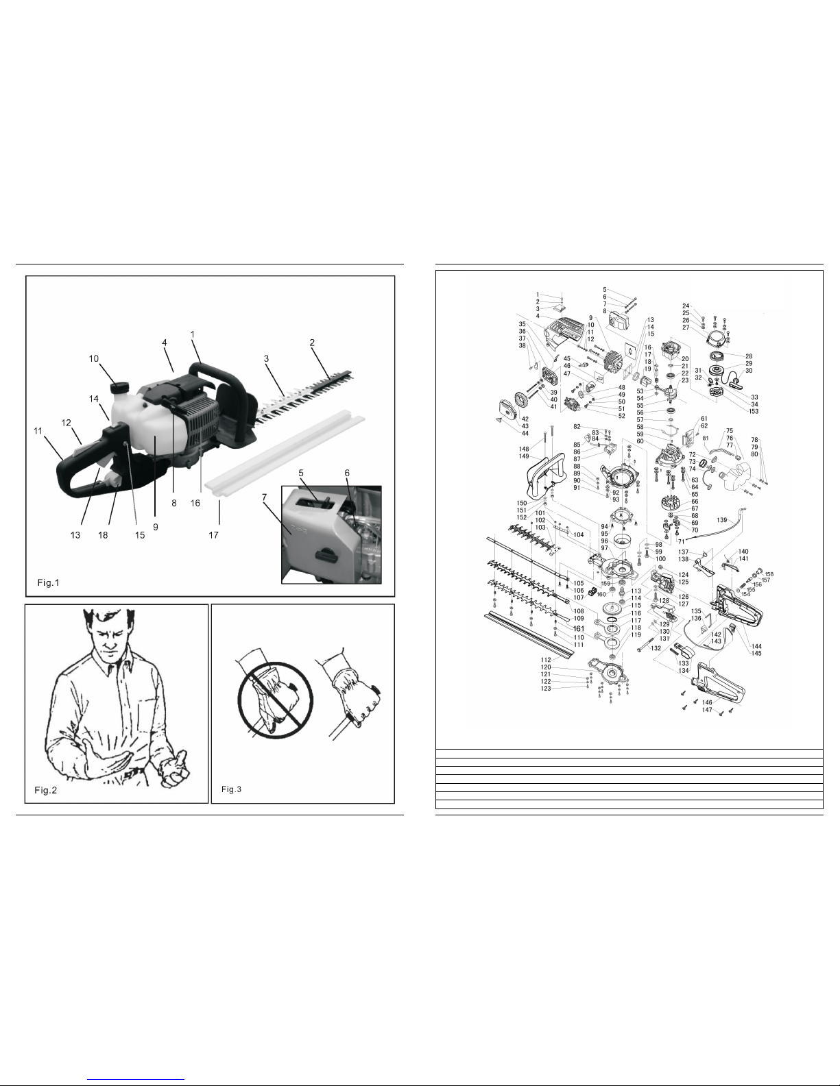
Description
Fig. 1
There are the safety decals on your hedge trimmer. Make sure the decals are legible and that you understand and follow the instructions on them.
1. Front handle guard
Comfortable, textured finish provides an anti-slip grip for the front hand. The guard protects the hands from the blades. Warning decals
are located on the guard.
2. Blades
Double reciprocating blades mounted to ablade support bar. The blades are double sided, capable of cutting on either side.
3. Blade stiffener
Attaches to the top of the blades and guides material being cut into the blades.
4. Spark plug
Provides spark to ignite fuel mixture.
5. Choke
The choke control lever is located on the front of the air cleaner case. Move the choke lever to “cold start” position to close the choke for
cold starting. Move the choke lever to “RUN” position to open the choke.
6. Primer bulb
Pumping the primer bulb before starting the engine draws fresh fuel from the fuel tank priming the carburettor for starting. Pump the
primer bulb until fuel is visible and flows freely in the clear fuel tank return line. Pump the bulb an additional 4 or 5 times.
7. Air cleaner
Contains the replaceable filter element.
8. Recoil starter handle
Pull the handle slowly until recoil starter engages, then quickly and firmly. Do not pull the rope the full distance or allow the handle to snap
back or damage to the starter will occur.
9. Fuel tank
Contains fuel and fuel filter.
10. Fuel tank cap
Covers and seals fuel tank opening.
11. Rear handle
Contains the stop switch, throttle lockout and throttle trigger.
12. Throttle trigger lockout
This lever must be depressed first before the throttle trigger can be activated.
13. Throttle trigger
Spring loaded to return to idle when released. Trigger lockout must be depressed fully before the throttle trigger will move. During
acceleration, depress gradually for best operating technique.
14. Ignition switch
“Ignition switch” located on the top of the rear handle. Press switch “I” to Run, press “STOP” to stop.
15. Lock button
The lock button will lock the throttle in the starting position in the manner: with the throttle trigger lockout lever depressed, depress throttle
trigger and push lock button, then slowly release the throttle trigger first, then the throttle lockout lever.
16. Muffler
The muffler controls exhaust noise and emission. Keep the exhaust area clear of flammable debris.
17. Blade cover
Used to cover blades during transportation or storage. Remove blade cover before using the hedge trimmer.
18. “Blocking” switch
Pull the “Blocking” switch, the handle can be rotated to several angles:45ºand 90º counterclockwise +45º and 90ºclockwise for good
control during operation.
2.SAFETY
Manual safety symbols and important information
Throughout this manual and on the product itself, you will find safety alerts and helpful, information messages preceded by symbols or key
words. The following is an explanation of those symbols and key words and what they mean to you:
Important:The enclosed message provides information necessary for the protection of the hedge trimmer
Note:This enclosed message provides tips for use, care and maintenance of the hedge trimmer.
In accordance with essential applicable safety standards of European directives.
This symbol accompanied with the words warning! and danger! draws attention to an act or condition that could lead to serious
personal injury to the operator and bystanders.
The circle with the slash symbol means whatever is shown within the circle is prohibited.
Please read and understand the manual.
Ferm 09
GB
D
NL
F
E
P
Saída de exaustão do cilindro (Nível 3)
Importante:a saída de exaustão do cilindro deve ser inspeccionada e limpa relativamente ao excesso de carbono a cada 3 meses ou 90
horas de funcionamento, de modo amanter o motor dentro do período de durabilidade de emissões. A FERM recomenda vivamente que
envie oaparador de sebes para a morada indicada no cartão da garantia para realizar este serviço de manutenção importante.
Fazer arodagem do motor
Os motores novos devem fazer uma rodagem mínima com dois depósitos de combustível antes de poderem ser feitos ajustes no
carburador. Durante operíodo de rodagem, o desempenho do motor aumenta e as emissões de exaustão estabilizam. Avelocidade ao
ralenti pode ser ajustada, se necessário.
Ajuste de altitude elevada (Nível 2)
Fig. 21 +22
Ferramentas necessárias
1 chave de fendas
1 tacómetro
Peças necessárias
Nenhuma.
Oajuste de altitude elevada não é necessário para um funcionamento correcto deste motor.
Nota:o funcionamento de cada aparador de sebes é verificado na fábrica e o carburador é regulado em conformidade com as disposições
sobre emissões. Ocarburador não dispõe de aceleração nem de agulhas de ajuste de alta velocidade.
Verifique avelocidade ao ralenti e reponha-a, se necessário. Se estiver disponível um tacómetro, o parafuso de regulação da velocidade ao
ralenti (H) deve ser regulado para as especificações indicadas na secção de especificações deste manual. Rode oparafuso da regulação da
velocidade ao ralenti (H) no sentido dos ponteiros do relógio para aumentar avelocidade ao ralenti; rode no sentido oposto ao dos ponteiros
do relógio para reduzir avelocidade ao ralenti.
Aviso! Quando concluir oajuste do carburador, não mova o acessório de corte, caso contrário podem ocorrer lesões pessoais
graves.
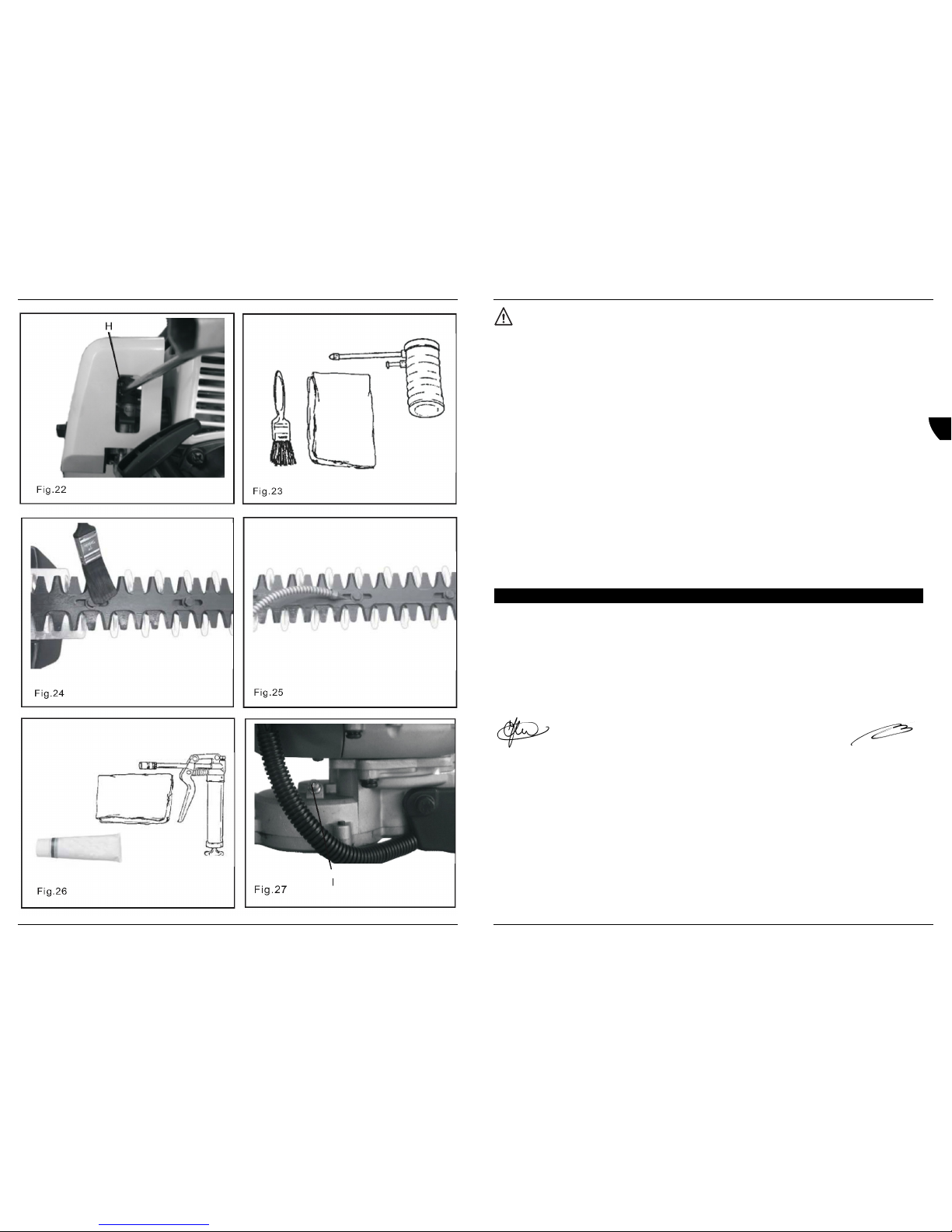
Lubrificação das lâminas (Nível 1)
Fig. 23 - 25
Ferramentas necessárias:
1 pano limpo
1 escova de limpeza, 25mm ou 50 mm
Peças necessárias:
1 óleo do motor, 20 W (lubrificação)
1 mistura de querosene e 20 W de óleo, 50-50 (limpeza).
Aviso! As lâminas do aparador de sebes são muito afiadas. Use luvas para proteger as mãos.
• Desligue oarame da vela de ignição da vela.
• Escova os resíduos da lâmina e revista ambos os lados com uma mistura de limpeza de 50-50.
• Deixe que amistura de limpeza amoleça o resíduo restante na lâmina e depois elimine-o.
• Aplique óleo limpo em toda asuperfície da lâmina. Certifique-se de que os parafusos da lâmina são lubrificados.
• Limpe oexcesso de óleo da lâmina antes de utilizar de novo o aparador de sebes.
Lubrificação da caixa de velocidades (Nível 1)
Fig.26 - 27
Ferramentas necessárias:
1 pistola de lubrificação
1 pano limpo
Peças necessárias:
1 massa lubrificante, 14 oz. ou baseada em lítio
• Limpe asujidade das juntas de lubrificação (I).
• Injecte cuidadosamente massa lubrificante nas juntas (I). Não force aentrada de massa lubrificante. Uma pressão excessiva força
apassagem de massa lubrificante pelas juntas, causando danos. Aplique 1 ou 2 bombas de massa lubrificante após 15 a 25 horas de
funcionamento.
• Limpe oexcesso de lubrificação à volta das juntas de lubrificação.
80 Ferm
GB
D
NL
F
E
P
Page 10

Filtro do combustível (Nível 1)
Fig. 11 + 12
Ferramentas necessárias:
1 Comprimento do arame com uma extremidade dobrada em gancho, 200 a250 mm
1 Pano limpo
1 Funil
1 Um recipiente para combustível aprovado
Peças necessárias:
1 kit de filtro de combustível e ar
Aviso! Ocombustível é altamente inflamável. Tenha muito cuidado ao misturar, armazenar ou manusear.
• Use um pano limpo para remover asujidade à volta da tampa do depósito e esvazie o depósito de combustível.
• Use ogancho do tubo de combustível para puxar o tubo de combustível e o filtro do depósito.
• Retire ofiltro do tubo e coloque o novo filtro.
Vela de ignição (Nível 2)
Fig. 13 + 14
Ferramentas necessárias:
1 cave emT
1 papa folgas
1 Escova metálica suave
Peças necessárias:
1 kit de afinação
Importante:utilize apenas a vela de ignição NGK BPMR7A, caso contrário podem ocorrer danos graves no motor.
• Retire avela de ignição e verifique se está suja, gasta ou se o eléctrodo central está arredondado.
• Limpe avela ou substitua por uma nova. Não utilize jacto de areia para limpar. Aareia que ficar no equipamento pode danificar o motor.
• Verifique e ajuste afolga da vela de ignição, dobrando o eléctrodo exterior.
• Aperte avela de ignição para 150-170 kg/cm.
Sistema de arrefecimento (Nível 2)
Fig. 15 - 20
Ferramentas necessárias:
1 chave de fendas
1 escova de limpeza, 25mm ou 50 mm (1 ou 2)
Ferramentas necessárias:
1 chave de fendas
1 escova de limpeza, 25mm ou 50 mm (1 ou 2)
Importante:para manter as temperaturas correctas de funcionamento do motor, deve haver uma corrente de ar frio através da área das
aletas do cilindro. Este fluxo de ar permite oarrefecimento do motor.
Pode ocorrer sobreaquecimento e falha do motor se:
• as entradas de ar no cárter estiverem bloqueadas, impedindo aentrada de ar de arrefecimento no cilindro.
• houver acumulação de pó e relva na parte exterior do cilindro. Esta acumulação isola omotor e impede a saída de calor. Aremoção de
bloqueios na conduta de arrefecimento do cárter ou alimpeza dos orifícios de arrefecimento é considerada manutenção normal.
Qualquer falha atribuída à falta de manutenção não é abrangida pela garantia.
Se ocorrer sobreaquecimento ou falha do motor, efectue oseguinte:
• Retire ofio e a tampa da vela de ignição.
• Retire oparafuso (F) da tampa do cilindro.
• Retire os parafusos inferiores direito (G) e esquerdo (G) da tampa do cilindro.
• Puxe com cuidado atampa do cilindro para a frente, puxe o fio da ignição e de saída de chama e coloque-a de parte.
• Aperte à mão atampa da vela de ignição para manter os resíduos do cilindro. Utilize uma escova para remover a sujidade das aletas do
cilindro.
Importante:não utilize um raspador de metal para retirar a sujidade das aletas do cilindro. Monte os componentes pela ordem inversa.
Monte novamente os componentes pela ordem inversa.
Nota:quando instalar a tampa do cilindro, deve colocar a tampa do interruptor de paragem no ilhó de borracha.
Ferm 79
GB
D
NL
F
E
P
Wear eye, ear and head protection.
Wear hand protection. Use two handed.
Wear slip resistant foot wear.
Emergency stop.
Choke control, “cold start” position (choke closed).
Choke control, “run position” (choke open).
Fuel and oil mixture.
Finger severing.
Hot surface.
Do not smoke near fuel.
Do not allow flames or sparks near fuel.
Ignition On/Off.
Do not operate without guards in place.
Avoid all power lines. This hedge trimmer is not insulated against electrical current.
Do not operate closer than 6M (20 ft) from electrical hazards. Keep bystanders at least 4.5 meters (15 feet) away. Plan retreat
path from falling objects.
Personal condition and safety equipment
Warning! Users of this product risk injury to themselves and others if the hedge trimmer is used incorrectly and/or safety
precautions are not followed. Correct clothing and safety gear must be worn when operating the hedge trimmer.
Physical condition
• Your judgment and physical dexterity may not be good:
• If you are tired or sick;
• If you are taking medication;
• If you have taken alcohol or drugs.
• Operate the hedge trimmer only if you are physically and mentally well.
Wear protection
• Wear eye protection that meets ANSI Z87.1 or CE requirements whenever you operate the hedge trimmer.
• Wear non-slip, heavy-duty work gloves to improve your grip on the handle. Gloves also reduce the transmission of machine vibration to
your hands.
• Wear hearing protection which meets CE requirements whenever the hedge trimmer is used.
Wear proper clothing
• Wear snug fitting, durable clothing;
• Trousers should have long legs, shirts should have long sleeves.
• Do not wear shorts.
• Do not wear ties, scarves or jewelry.
10 Ferm
GB
D
NL
F
E
P
Page 11

• Wear protective hair covering to contain long hair.
• Wear sturdy work shoes with non slip soles;
• Do not wear open toed shoes;
• Do not operate the hedge trimmer barefooted.
Hot Humid Weather
Heavy protective clothing can increase operator fatigue which can lead to heat stroke. Schedule heavy work for early morning or late
afternoon hours when temperatures are cooler.
Extended operation and extreme conditions
Fig. 2
It is believed that acondition called Raynaud’s phenomenon, which affects the fingers of certain individuals, may be brought about by
exposure to vibrations and cold. Exposure to vibrations and cold may cause tingling and burning sensations, followed by aloss of color and
numbness in the fingers. The following precautions are strongly recommended, because the minimum exposure, which could trigger the
ailment, is unknown.
• Keep your body warm, especially the head, neck, feet, ankles, hands, and wrists.
• Maintain good blood circulation by performing vigorous arm exercises during frequent work breaks, and also by not smoking.
• Limit the hours of operation. Try to fill each day with jobs where operating the hedge trimmer or other hand-held power equipment is not required.
• If you experience discomfort, redness and swelling of the fingers followed by whitening and loss of feeling, consult your physician before
further subjecting yourself to cold and vibrations.
Warning! Do not operate this product indoors or in inadequately ventilated areas. The engine exhaust contains poisonous
emissions and can cause serious injury or death.
Repetitive Stress Injuries
Fig. 3
It is believed that overusing the muscles and tendons of the fingers, hands, arms, and shoulders can cause soreness, swelling, numbness,
weakness, and extreme pain in those areas. Certain repetitive hand activities may put you at ahigh risk for developing a Repetitive Stress
Injury (RSI). An extreme RSI condition is Carpal Tunnel Syndrome (CTS), which can occur when your wrist swells and squeezes avital nerve
that runs through the area. Some believe that prolonged exposure to vibrations may contribute to CTS. CTS can cause severe pain for
months or even years. To reduce the risk of RSI/CTS, do the following:
• Avoid using your wrist in abent, extended, or twisted position. Instead, try to maintain a straight wrist position. Also, when grasping, use
your whole hand, not just the thumb and index finger.
• Take periodic breaks to minimize repetition and rest your hands.
• Reduce the speed and force with which you do the repetitive movement.
• Do exercise to strengthen the hand and arm muscles.
• Immediately stop using all power equipment and consult adoctor if you feel tingling, numbness, or pain in the fingers, hands, wrists, or
arms. The sooner RSI/CTS is diagnosed, the more likely permanent nerve and muscle damage can be prevented.
Clear the work area
Fig. 4
Spectators and fellow workers must be warned, and children and animals prevented from coming closer than 15m (50 ft.) while the hedge
trimmer is in use.
Keep afirm grip and a solid stance
Fig. 4
• Hold the front and rear handles with both hands, with thumbs and fingers encircling the handles.
• Maintain footing and balance at all times. Do not stand on slippery, uneven or unstable surfaces. Do not work in odd positions or on
ladders. Do not over reach.
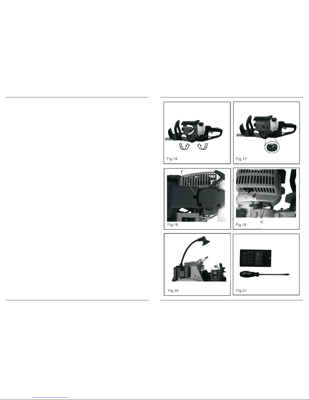
Turnable handle
Fig. 5
To have good control during operating, the hedge trimmer is equipped with aturnable handle. The handle can be rotated to several angles:
45° and 90° counterclockwise + 45° and 90° clockwise.
• Pull the yellow blocking switch (A) backwards and rotate the handle to the desired angle.
• Release this blocking switch (A) again and rotate the handle till it clicks into the correct position. The blocking switch (A) will automatically
return to its original position.
• Check if the handle is now locked in the new position.
Avoid Hot Surfaces
Keep the exhaust area clear of flammable debris. Avoid contact during and immediately after operation.
Warning! Never perform blade maintenance procedures while the engine is running.
Ferm 11
GB
D
NL
F
E
P
Procedimentos de manutenção "Faça você mesmo"
Códigos de procedimento de manutenção
I = Inspeccionar
R = Substituir
C = Limpar
(1) = Aplicar lubrificação acada 15 - 25 horas de utilização.
(2) = Inspeccione alâmina, limpe-a e afie-a, conforme necessário. Lubrifique as lâminas periodicamente durante a utilização.
* = Todas as recomendações de substituição baseiam-se na localização de danos ou desgaste durante ainspecção.
Filtro do ar (Nível 1))
Fig. 8-10
Ferramentas necessárias:
1 Escova de limpeza, 25mm ou 50 mm
Peças necessárias:
1 Kit de filtro de combustível e ar
• Feche oobturador na posição “arranque a frio”. Isto impede a entrada de sujidade no tubo do carburador ao retirar o filtro do ar. Escova
asujidade acumulada na área do dispositivo de limpeza do ar.
• Retire atampa do dispositivo de limpeza do ar. Limpe e verifique se a peça está danificada. Se a peça estiver embebida em combustível
e muito suja, deve substituí-la.
• Se puder limpar e reutilizar apeça, certifique-se de que:
• se encaixa na cavidade da tampa do dispositivo de limpeza do ar.
• é instalada com olado original virado para fora.
Nota:pode ser necessário ajustar o carburador depois de substituir ou limpar o filtro do ar.
Componente/
Sistema
Procedimento de
manutenção
Nível de
habilitação
necessário
Utilização
diária ou
anterior
Durante cada
abasteciment
o
3 meses ou
90 horas
6 meses ou
270 horas
Anualmente
ou 600 horas
Filtro do ar Inspeccionar/
Limpar/Substituir
1 I L - S * - -
Obturador Inspeccionar/
Limpar
2I L - ---
Filtro do
combustível
Inspeccionar/
Substituir
1- -I-S *
Sistema de
combustível,
fugas
Inspeccionar/
Substituir
1I * I I --
Sistema de
arrefecimento
Inspeccionar/
Limpar
2I L - - --
Caixa de
velocidades
Lubrificar 2 I (1) - - - -
Lâminas Inspeccionar/
Limpar
1 I L(2) - - - -
Cordão do motor
de arranque
Inspeccionar/
Limpar
1I L* - - - -
Vela de ignição Inspeccionar/
Limpar
2- -I LS *-
Parafusos,
porcas, parafusos
com porca
Inspeccionar/
Apertar/Substituir
1 I S * - - - -
78 Ferm
GB
D
NL
F
E
P
Page 12
Aviso! Se omotor não parar depois de colocar o botão de paragem na posição “STOP” (Parar), feche o obturador (posição de
arranque afrio) para parar o motor. Para reparar o botão de paragem do aparador de sebes, envie-o para o nome e morada
indicada no cartão de garantia.
Aparar sebes
Fig. 7
• Segure oaparador com firmeza e carregue no gatilho de aceleração para aumentar a velocidade do motor.
• Incline oaparador para que os dentes de corte fiquem ligeiramente inclinados na direcção da sebe ou arbusto e inicie o corte.
Aviso! Nunca retire as mãos do aparador de sebes quando as lâminas estiverem em movimento.
Aviso! Omotor continua a funcionar, mesmo se as lâminas tiverem parado devido a um obstáculo. Se isto ocorrer, pare o motor,
desligue ocabo de ignição e retire o obstáculo.
4. MANUTENÇÃO
Oaparador de sebes foi concebido para proporcionar muitas horas de funcionamento sem problemas. Uma manutenção regular
programada do aparador de sebes permite atingir esse objectivo. Se não tiver acerteza ou não dispuser das ferramentas necessárias, deve
enviar oaparador para a morada indicada no cartão de garantia para ter assistência. Foi atribuída uma classificação a cada tarefa de
manutenção, para ajudá-lo adecidir se pretende reparar o equipamento sozinho ou enviá-lo para a assistência. Se uma tarefa não estiver
incluída, envie oequipamento a reparar para a morada indicada no cartão de garantia.
Nível de experiência
Nível 1 = Fácil de reparar. Amaioria das ferramentas necessárias é fornecida com oaparador de sebes.
Nível 2 = Dificuldade média. Podem ser necessárias algumas ferramentas específicas.
Nível 3 = É necessário experiência. São necessárias ferramentas específicas. AFerm recomenda que o aparador de sebes a reparar seja
enviado para amorada indicada no cartão de garantia.
AFerm oferece kits e peças de manutenção para que o trabalho de manutenção seja mais fácil. Abaixo de cada título de tarefa são
apresentadas as várias referências necessárias para arespectiva tarefa. Veja a morada indicada no cartão de garantia relativo a estas
peças.
Intervalos de manutenção
Procedimentos de manutenção da assistência
Componente/
Sistema
Procedimento
de manutenção
Nível de
habilitação
necessário
Utilização
diária ou
anterior
Durante cada
abasteciment
o
3 meses ou
90 horas
6 meses ou
270 horas
Anualmente
ou 600 horas
Saída de
exaustão do
cilindroInspect/
Clean/
Inspeccionar/
Limpar/
Descarbonizar
3- -I C--
Afiar lâminas Inspeccionar/
Limpar
3 I (2) - - - -
Ferm 77
GB
D
NL
F
E
P
Equipment check
Warning! Use only FERM approved attachments. Serious injury may result from the use of anon-approved attachment
combination. FERM will not be responsible for the failure of cutting devices, attachments or accessories which have not been
tested and approved by FERM. Please read and comply with all safety instructions listed in this manual and safety manual.
• Check the hedge trimmer for loose/missing nuts, bolts, and screws. Tighten and/ or replace as needed.
• Inspect fuel lines, tank, and the area around the carburettor for fuel leaks. Do not operate the hedge trimmer if leaks are found.
• Inspect the shield for damage. Ensure that the blade stiffener is securely in place.
• Replace if either is damaged or missing.
• Check that the cutting attachment is firmly attached and in safe operating condition.
• Check that the blade stiffener is not damaged or distorted and replace the blade stiffener if it is bent or damaged.
3 . OPERATION
Fuel Requirements
Petrol
Use 89 Octane [R+M/2] (mid grade or higher) petrol known to be good quality. Petrol may contain up to 15% MTBE (methyl tertiary-butyl
ether). Petrol containing methyl (wood) alcohol is not approved.
Two Stroke Oil
Atwo-stroke engine oil meeting ISO-L-EGD (ISO/CD 13738) and J.A.S.O. FC standards must be used. Engine problems due to inadequate
lubrication caused by failure to use an ISOLEGD and J.A.S.O. FC certified oil will invalidate the two-stroke engine warranty. (Emission
related parts only are covered for two years, regardless of two stroke oil used, per the statement listed in the Emission Defect Warranty
Explanation.)
Fuel to oil mix 25:1 ratio
Gas in liters Oil in cc.
4 160
8 320
20 800
Important: Regardless of the mixing ratio mentioned in the corresponding manuals, premium grade 2-cycle oil can be used for all previously
built Ferm engines.
Handling Fuel
Warning! Fuel is very flammable. Use extreme care when mixing, storing or handling or serious personal injury
could result.
• Use an approved fuel container.
• Do not smoke near fuel.
• Do not allow flames or sparks near fuel.
• Fuel tanks/cans may be under pressure. Always loosen fuel caps slowly allowing pressure to equalise.
• Never refuel the hedge trimmer when the engine is hot or running!
• Do not fill fuel tanks indoors. Always fill fuel tanks outdoors over bare ground.
• Do not overfill fuel tank. Wipe up spills immediately.
• Securely tighten the fuel tank cap and close fuel container after refueling.
• Inspect for fuel leakage. If fuel leakage is found, do not start or operate the hedge trimmer until leakage is repaired.
• Move at least 3m (10 ft.) from the refueling location before starting the engine.
Mixing Instructions
• Fill an approved fuel container with half of the required amount of petrol.
• Add the correct amount of 2-stroke oil to petrol.
• Close container and shake to mix oil with petrol.
• Add remaining petrol, close fuel container, and remix.
Spilt fuel is aleading cause of hydrocarbon emissions. Some countries may require the use of automatic fuel shut-off containers to reduce fuel spillage.
After use
Do not store the hedge trimmer with fuel in its tank. Leaks can occur. Return unused fuel to an approved fuel storage container.
Storage
Fuel storage laws vary by locality. Contact your local government for the laws affecting your area. As aprecaution, store fuel in an approved,
airtight container. Store in awell ventilated, unoccupied building away from sparks and naked flames.
Important:Stored fuel ages. Do not mix more fuel than you expect to use in thirty (30) days, ninety (90) days when a fuel stabilizer is added.
Important:Stored two-stroke fuel may separate. Always shake the fuel container thoroughly before each use.
12 Ferm
GB
D
NL
F
E
P
Page 13

Starting acold engine
Fig. 6
Note:The blade cover is used for transportation and storage. Remove blade cover before using the hedge trimmer.
• Add fuel: always use this product with fuel, which is mixed with 2-stroke oil with ratio 25:1.
• Set ignition switch (B) to the “I” position (ON position)
• Press the priming bulb several times until fuel is visible and flows freely in the clear fuel tank return line.
• Lock the throttle in the starting position: with the throttle trigger lockout lever (C) depressed, depress throttle trigger (D) and push lock
button (E), then slowly release the throttle trigger (D) first, then the throttle lockout lever(C).
• Set the choke lever to the cold start (closed) position.
• Pull the recoil starter briskly, when you hear the engine start, return the choke lever to “I” position (ON position), then pull recoil starter
briskly again until the engine runs.
• After starting engine, press throttle trigger (D) to release throttle lock, then allow engine to run for several minutes to warm up
• After engine warm-up, press throttle trigger (D) gradually to get operating speed.
Note:If engine does not start, repeat instructions 4- 6.
Warning! The blades should not move when idle. If the blades move, readjust the carburettor according to carburettor adjustment
instructions in this manual or see the address on the warranty card, otherwise serious personal injury could result.
After engine warm-up, grip the handle to depress the throttle trigger lockout, and gradually depress throttle trigger to increase engine rpm to
operating speed.
Starting warm engine
Fig. 6
The starting procedure is the same as for cold start except do not close the choke.
Warning! The blades should not move when idle. If the blades move, readjust the carburettor according to carburettor adjustment
instructions in this manual or see the address on the warranty card, otherwise serious personal injury could result.
• Set ignition switch (B) to the “I” position (ON position)
• Press the priming bulb several times until fuel is visible and flows freely in the clear fuel tank return line.
• Lock the throttle in the starting position: with the throttle trigger lockout lever (C) depressed, depress throttle trigger (D) and push lock
button (E), then slowly release the throttle trigger (D) first, then the throttle lockout lever(C).
• Pull the recoil starter briskly until the engine runs.
Note:If the engine does not start, use the cold start procedure.
Stopping engine
• Release the throttle and allow engine to return to idle before shutting off engine.
• Move ignition switch (B) to “STOP” position.
• In case of emergency, directly set ignition switch to the “STOP” position.
Warning! If the engine does not stop when the stop switch is moved to “STOP” position, close the choke -cold start position - to
stall the engine. Have the hedge trimmer stop switch repaired at the name and address shown on the warranty card.
Hedge trimming
Fig. 7
• Hold the trimmer firmly and squeeze the throttle trigger to accelerate the engine.
• Tilt trimmer so the cutting teeth are angled slightly toward the hedge or shrub and proceed to cut.
Warning! Never remove hands from the hedge trimmer when the blades are moving.
Warning! The engine will continue running even when the blades have stopped due to an obstruction. If this occurs, stop the
engine, disconnect the ignition cable and remove the obstruction.
4. MAINTENANCE
Your hedge trimmer is designed to provide many hours of trouble free service. Regular scheduled maintenance will help your hedge trimmer
achieve that goal. If you are unsure or are not equipped with the necessary tools, you may want to take your hedge trimmer to the address on
the warranty card for maintenance. To help you decide whether you want to do it yourself or have the address on the warranty card do it, each
maintenance task has been graded. If atask is not listed, see the address on the warranty card for repairs.
Skill levels
Level 1 = Easy to do. Most required tools come with hedge trimmer.
Ferm 13
GB
D
NL
F
E
P
• Feche orecipiente e agite-o para misturar o óleo com a gasolina.
• Adicione agasolina restante, feche o recipiente e volte a misturar.
Combustível derramado é aprincipal causa de emissões de hidrocarboneto. Alguns países podem exigir a utilização de recipientes de
combustível com válvula de fecho automático para reduzir oderrame de combustível.
Após autilização
Não guarde oaparador de sebes com combustível no depósito. Podem ocorrer fugas. Coloque o combustível não usado num recipiente
aprovado para armazenamento de combustível.
Armazenamento
Alegislação relacionada com o armazenamento varia consoante a localização. Contacte o seu governo local para conhecer a legislação da
sua área. Como precaução, guarde ocombustível num recipiente aprovado e bem fechado. Guarde-o num edifício devidamente ventilado e
desocupado, afastado de faíscas e chamas vivas.
Importante:o combustível armazenado perde qualidade. Misture apenas o combustível que pretende utilizar durante trinta (30) dias ou
durante noventa (90) dias, no caso de ter adicionado um estabilizador.
Importante:o combustível para motor a 2 tempos armazenado pode separar-se. Agite sempre com vigor o recipiente de combustível antes
de cada utilização.
Arranque de um motor frio
Fig. 6
Nota:a capa da lâmina é utilizada para o transporte e armazenamento. Retire a capa da lâmina antes de utilizar o aparador de sebes.
Adicione combustível: utilize sempre este produto com ocombustível, o qual é misturado com óleo para motor a 2 tempos numa proporção de 25:1.
• Coloque obotão de ignição (B) na posição “I” (posição ON (Ligar))
• Carregue várias vezes na bomba até ocombustível ser visível e circular livremente na conduta de retorno do depósito de combustível.
• Bloqueie oacelerador na posição de arranque: com a patilha de bloqueio do gatilho de aceleração (C) premida, carregue no gatilho de
aceleração (D) e no botão de bloqueio de pressão (E), liberte lentamente ogatilho de aceleração (D) e depois a patilha de bloqueio de
aceleração (C).
• Coloque apatilha do obturador na posição de arranque a frio (fechado).
• Puxe ocordão do motor de arranque com força, quando ouvir o motor a arrancar, volte a colocar a patilha do obturador na posição “I”
(ON (Ligado)) e depois puxe novamente acorda de arranque com força até o motor arrancar.
• Depois de ligar omotor, carregue no gatilho de aceleração (D) para libertar o bloqueio de aceleração e depois deixe o motor a funcionar
durante alguns minutos para aquecer.
• Depois do motor aquecer, carregue gradualmente no gatilho de aceleração (D) para atingir avelocidade de funcionamento.
Nota:se o motor não arrancar, repita as instruções 4 a 6.
Aviso! As lâminas não devem mover-se quando omotor estiver em ralenti. Se as lâminas se moverem, ajuste de novo
ocarburador de acordo com as instruções indicadas neste manual ou veja a morada indicada no cartão de garantia, caso
contrário podem ocorrer lesões pessoais graves.
Após oaquecimento, segure na pega para carregar no bloqueio do gatilho de aceleração e carregue gradualmente no gatilho de aceleração
para aumentar as rotações do motor até avelocidade de funcionamento.
Arranque de um motor quente
Fig. 6
Oprocesso de arranque é semelhante ao do arranque a frio, mas não deve fechar o obturador.
Aviso! As lâminas não devem deslocar-se durante oralenti. Se as lâminas se moverem, ajuste de novo o carburador de acordo
com as instruções indicadas neste manual ou veja amorada indicada no cartão de garantia, caso contrário podem ocorrer
lesões pessoais graves.
• Coloque obotão de ignição (B) na posição “I” (posição ON (Ligar))
• Carregue várias vezes na bomba até ocombustível ser visível e circular livremente na conduta de retorno do depósito de combustível.
• Bloqueie oacelerador na posição de arranque: com a patilha de bloqueio do gatilho de aceleração (C) premida, carregue no gatilho de
aceleração (D) e no botão de bloqueio de pressão (E), liberte lentamente ogatilho de aceleração (D) e depois a patilha de bloqueio de
aceleração (C).
• Puxe ocordão do motor de arranque com força até o motor arrancar.
Nota:se o motor não arrancar, utilize o processo de arranque a frio.
Para parar omotor
• Liberte oacelerador e deixe que o motor volte à velocidade de ralenti antes de o desligar.
• Coloque obotão de ignição (B) na posição “STOP” (Parar).
• Em caso de emergência, coloque de imediato obotão de ignição na posição “STOP” (Parar).
76 Ferm
GB
D
NL
F
E
P
Page 14

• Verifique se apega está bloqueada na nova posição.
Evite tocar em superfícies quentes
Mantenha asaída de escape sem resíduos inflamáveis. Evite tocar em superfícies quentes durante ou imediatamente após a utilização do
equipamento.
Aviso! Nunca realize trabalhos de manutenção na lâmina enquanto omotor estiver a funcionar.
Verificação do equipamento
Aviso! Utilize apenas acessórios Ferm aprovados. Podem ocorrer lesões graves resultantes da utilização de acessórios não
aprovados. AFerm não se responsabiliza por falhas nos dispositivos ou acessórios de corte que não tenham sido testados ou
aprovados pela Ferm. Leia e siga todas as instruções de segurança indicadas neste manual e no manual de segurança.
• Verifique se existem porcas, parafusos com porca e parafusos soltos no aparador de sebes. Aperte e/ ou substitua as peças conforme
necessário.
• Verifique se existem fugas de combustível nos tubos de alimentação, no depósito e na zona à volta do carburador. Se encontrar fugas,
não utilize oaparador de sebes.
• Verifique se existem danos na protecção. Certifique-se de que oesticador da lâmina está devidamente colocado.
• Substitua-o se estiver danificado ou coloque-o se não estiver instalado.
• Verifique se oacessório de corte está colocado correctamente e em boas condições de funcionamento.
• Verifique se oesticador da lâmina não está danificado ou deformado e substitua-o se estiver dobrado ou danificado.
3 . COMANDOS DE FUNCIONAMENTO
Requisitos do combustível
Gasolina
Utilize gasolina de 89 octanas [R+M/2] (grau médio ou superior), conhecida pelo seu bom nível de qualidade. Agasolina pode conter até
15% de MTBE (Éter metil tert-butílico). Não é aprovada gasolina que contenha álcool metileno (madeira).
Óleo para motor a2 tempos
Deve utilizar um óleo para motor a2 tempos em conformidade com as normas ISO-L-EGD (ISO/CD 13738) e J.A.S.O. FC. Os problemas do
motor relacionados com lubrificação inadequada devido à não utilização de óleo em conformidade com as normas ISOLEGD e J.A.S.O. FC
invalida agarantia do motor a 2 tempos. (As peças relacionadas com emissões são abrangidas apenas durante dois anos,
independentemente do óleo para motor a2 tempos utilizado, de acordo com a instrução indicada na Explicação da Garantia de Defeitos de
Emissão.)
Mistura de combustível e óleo, numa proporção de 25:1
Gasolina em litros Óleo em cc.
4 160
8 320
20 800
Importante: independentemente da proporção de mistura referida nos manuais correspondentes, o óleo para motor a 2 tempos de
excelente qualidade pode ser utilizado em todos os motores Ferm anteriores.
Manuseamento de combustível
Aviso! Ocombustível é muito inflamável. Tenha muito cuidado ao misturar, armazenar ou amanusear o combustível, porque
podem ocorrer lesões pessoais.
• Utilize um recipiente para combustível aprovado.
• Não fume perto de combustível.
• Não faça chamas nem faíscas perto de combustível.
• Os depósitos/latas de combustível podem estar sob pressão. Desaperte sempre lentamente as tampas do depósito de combustível
para permitir alibertação da pressão.
• Nunca encha odepósito do aparador de sebes quando o motor estiver quente ou em funcionamento!
• Não encha odepósito em locais fechados. Encha sempre o depósito em locais abertos e desimpedidos.
• Não encha demasiado odepósito de combustível. Limpe de imediato qualquer derrame de combustível.
• Aperte bem atampa do depósito de combustível e feche o recipiente depois de encher o depósito.
• Verifique se há fugas de combustível. Se encontrar alguma fuga, não inicie nem utilize oaparador enquanto a fuga não for reparada.
• Coloque-se auma distância de, pelo menos, 3 m do local de reabastecimento antes de ligar o motor.
Instruções de mistura
• Encha um recipiente aprovado com metade da quantidade de gasolina necessária.
• Adicione aquantidade correcta óleo para motor a 2 tempos à gasolina.
Ferm 75
GB
D
NL
F
E
P
Level 2 = Moderate difficulty. Some specialized tools may be required.
Level 3 = Experience required. Specialized tools are required. Ferm recommend that the hedge trimmer be returned to the address on the
warranty card for service.
Ferm offers maintenance kits and parts to make your maintenance job easier. Just below each task heading are listed the various part
numbers required for that task. See the address on the warranty card for these parts.
Maintenance intervals
Service address maintenance procedures
Do-It-Yourself maintenance procedures
Maintenance procedure codes
I = Inspect
R = Replace
C = Clean
(1) = Apply lubrication every 15 - 25 hours of use.
(2) = Inspect blade and clean and sharpen as needed. Lubricate blades periodically during use.
* = All recommendations for replacing are based on the finding of damage or wear during inspection.
Air filter (Level 1)
Fig. 8-10
Tools required:
1 Cleaning brush, 25mm or 50 mm (1” or 2”)
Parts required:
1 Air & Fuel filter kit
• Close the choke in “cold start” position. This prevents dirt from entering the carburettor throat when the air filter is removed. Brush out
accumulated dirt from the air cleaner area.
Component /
System
Maintenance
procedure
Required
skill level
Daily or
before use
During every
refueling
3 Months
or 90 hours
6 Months
or 270 hours
Annually
or 600 hours
Air filter Inspect/Clean/
Replace
1 I C - R * - -
Choke Inspect/Clean 2 I C - - - -
Fuel filter Inspect/Replace 1 - - I - R *
Fuel system, leaks Inspect/Replace 1 I * I I - -
Cooling system Inspect/Clean 2 I C - - - -
Gear housing Grease 2 I (1) - - - -
Blades Inspect/Clean 1 I C (2) - - - -
Recoil starter rope Inspect/Clean 1 I C * - - - -
Spark plug Inspect/Clean 2 - - I C R * -
Screws, nuts, bolts Inspect/Tighten/
Replace
1 I R * - - - -
Component /
System
Maintenance
procedure
Required
skill level
Daily or before
use
During every
refueling
3 Months
or 90 hours
6 Months
or 270 hours
Annually
or 600 hours
Cylinder
exhaust port
Inspect/Clean/
Decarbonise
3- -I C--
Sharpen blades Inspect/Clean 3 I (2) - - - -
14 Ferm
GB
D
NL
F
E
P
Page 15

• Remove the air cleaner cover. Clean and inspect the element for damage. If element is fuel soaked and very dirty, then replace.
• If the element can be cleaned and reused, be certain it:
• Still fits the cavity in the air cleaner cover.
• Is installed with the original side out.
Note:Carburettor adjustment may be needed after air filter cleaning or replacement.
Fuel filter (Level 1)
Fig. 11 + 12
Tools required:
1 Length of wire with one end bent into ahook, 200-250 mm (8-10”)
1 Clean rag
1 Funnel
1 An approved fuel container
Parts required:
1 Air & fuel filter kit
Warning! Fuel is highly inflammable. Use extreme care when mixing, storing or handling.
• Use aclean rag to remove loose dirt from around fuel cap and empty fuel tank.
• Use the fuel line hook to pull the fuel line and filter from the tank.
• Remove the filter from the line and install the new filter.
Spark plug (Level 2)
Fig. 13 + 14
Tools required:
1 T-wrench
1 Feeler gauge
1 Soft metal brush
Parts required:
1 Tune-up kit
Important:Use only NGK BPMR7A spark plug otherwise severe engine damage can occur.
• Remove the spark plug and check for soiling, worn and rounded centre electrode.
• Clean the plug or replace with anew one. Do not sand blast to clean. Remaining sand will damage the engine.
• Check and adjust the spark plug gap by bending outer electrode.
• Tighten the spark plug to 150-170 kg/cm (130-150 inch/lb.).
Cooling system (Level 2)
Fig. 15 - 20
Tools required:
1 Screwdriver
1 Cleaning brush, 25mm or 50 mm (1 or 2)
Parts required:
None if you are careful.
Important:To maintain correct engine operating temperatures, cooling air must pass freely through the cylinder fin area. This flow of air
carries combustion heat away from the engine.
Overheating and engine seizure can occur when:
• Air intakes in the crankcase are blocked, preventing cooling air from reaching the cylinder.
• Dust and grass build up on the outside of the cylinder. This build up insulates the engine and prevents the heat from leaving. Removal of
crankcase cooling passage blockages or cleaning of cooling fins is considered as normal maintenance. Any failure attributed to lack of
maintenance is not warranted.
When overheating and engine seizure occur do the following:
• Remove the spark plug lead and spark plug cap.
• Remove screw (F) from the cylinder cover.
• Remove bottom right (G) and bottom left (G) screws from cylinder cover.
• Carefully pull the cylinder cover forward, pull the ignition lead and the flameout lead and put aside.
• Loosely install the spark plug cap to keep debris out of the cylinder. Use abrush to remove dirt from cylinder fins.
Important: Do not use ametal scraper to remove dirt from the cylinder fins. Assemble components in reverse order.
Ferm 15
GB
D
NL
F
E
P
• Use protecção auditiva que esteja em conformidade com os requisitos da CE sempre que utilizar oaparador de sebes.
Use vestuário adequado
• Use vestuário apertado e resistente;
• As calças devem ser compridas e as camisas devem ter mangas compridas.
• Não use calções.
• Não use camisas, lenços ou jóias.
• Se tiver ocabelo comprido, use uma rede para o tapar.
• Use calçado de segurança robusto com solas antiderrapantes;
• Não use calçado aberto;
• Não utilize oaparador de sebes descalço.
Clima húmido e quente
Ovestuário de elevada protecção pode aumentar a fadiga do operador, dando origem a um possível ataque de coração. Programe as
tarefas mais pesadas para oinício da manhã ou ao fim da tarde, quando a temperatura é mais fresca.
Utilização prolongada e condições extremas
Fig. 2
Supõe-se que adoença conhecida por fenómeno de Raynaud, que afecta os dedos de algumas pessoas, pode ocorrer devido à exposição
avibrações e ao frio. A exposição a vibrações e ao frio pode causar uma sensação de formigueiro e de ardor, seguida de perda de cor e
dormência dos dedos. Uma vez que se desconhece onível de exposição mínima, que pode originar a dor, recomendam-se vivamente as
seguintes precauções:
• Mantenha ocorpo quente, especialmente a cabeça, pescoço, pés, tornozelos, mãos e pulsos.
• Estimule acirculação sanguínea, efectuando exercícios vigorosos com os braços durante as pausas, não devendo também fumar.
• Limite onúmero de horas de utilização. Tente realizar tarefas em que não seja necessário utilizar o aparador de sebes ou outro tipo de
equipamento eléctrico manual.
• Se sentir desconforto e verificar que os dedos ficam inchados e vermelhos e, em seguida, esbranquiçados, com perda de sensibilidade,
consulte oseu médico antes de se sujeitar ao frio e a vibrações.
Aviso! Não utilize em equipamento em interiores ou em zonas sem ventilação adequada. Ofumo de escape do motor contém
emissões tóxicas e pode causar lesões graves ou amorte.
Lesões por Esforços Repetitivos
Fig. 3
Supõe-se que oesforço excessivo dos músculos e tendões dos dedos, mãos, braços e ombros pode causar ferimento, inchaço, dormência,
fraqueza e dor excessivo nessas zonas. Determinadas actividades manuais repetitivas podem colocar asua saúde em risco, podendo
originar Lesões por Esforços Repetitivos (LER). Uma condição extrema de LER é oSindroma do Canal Cárpico (SCC), que pode ocorrer
quando opulso incha e aperta um nervo vital nessa área. Supõe-se que a exposição prolongada a vibrações pode contribuir para o SCC.
Asíndrome SCC pode causar dores graves durante meses ou mesmo anos.
Para reduzir orisco de LER/SCC, efectue as seguintes medidas:
• Evite colocar opulso numa posição dobrada, estendida ou torcida. Em vez disso, tente mantê-lo numa posição direita. Além disso, ao
agarrar oaparador, utilize toda a mão e não apenas o polegar e o indicador.
• Faça pausas regulares para minimizar arepetição e descanse as mãos.
• Reduza avelocidade e a força com que exerce o movimento repetitivo.
• Pratique exercício físico para fortalecer os músculos da mão e do braço.
• Se sentir formigueiro, dormência ou dores nos dedos, pulsos ou braços, desligue imediatamente oequipamento e consulte um médico.
Quanto mais prematuro for odiagnóstico de LER/SCC, maior será a possibilidade de prevenir danos permanentes nos nervos e músculos.
Limpar aárea de trabalho
Fig. 4
Quando utilizar oaparador de sebes, os transeuntes e colegas de trabalhos devem estar avisados e as crianças e animais devem manter-se
auma distância superior a 15 m.
Agarre com firmeza e mantenha uma posição firme
Fig. 4
• Segure nas pegas frontal e traseira com ambas as mãos, rodeando as pegas com os polegares e os dedos.
• Mantenha-se sempre numa posição e equilíbrio estáveis. Não se coloque sobre superfícies derrapantes, desequilibradas ou instáveis.
Não trabalhe em posições instáveis nem em cima de escadas. Não se incline.
Pega rotativa
Fig. 5
Oaparador de sebes está equipado com uma pega rotativa para um melhor controlo durante o trabalho. A pega pode ser rodada para vários
ângulos: 45° e 90° no sentido oposto ao dos ponteiros do relógio + 45° e 90° no sentido dos ponteiros do relógio.
• Puxe ointerruptor de bloqueio amarelo (A) para trás e rode a pega para o ângulo desejado.
• Liberte de novo este botão de bloqueio (A) e rode apega até ouvir um clique que corresponde à posição correcta. O interruptor de
bloqueio (A) volta automaticamente para aposição original.
74 Ferm
GB
D
NL
F
E
P
Page 16

Ocírculo com uma barra oblíqua significa que o que estiver indicado dentro do círculo é proibido.
Leia e compreenda oconteúdo do manual.
Use protecção para os olhos, ouvidos e cabeça.
Use luvas de protecção. Use as luvas de protecção em ambas as mãos.
Use calçado antiderrapante.
Paragem de emergência.
Controlo do obturador, posição de “arranque afrio” (obturador fechado).
Controlo do obturador, “posição de marcha” (obturador aberto).
Mistura de combustível e óleo.
Risco de corte dos dedos.
Superfície quente.
Não fume perto de combustível.
Não faça lume nem provoque faíscas perto de combustível.
Ligar/desligar ignição.
Não utilize oequipamento sem as protecções colocadas.
Evite ocontacto com linhas de corrente eléctrica. Este aparador de sebes não está isolado contra corrente eléctrica.
Não utilize oequipamento a uma distância inferior a 6 m de fontes de corrente eléctrica. Mantenha os transeuntes a uma
distância de, pelo menos, 4,5 metros. Planeie um percurso de fuga relativamente aobjectos que possam cair.
Equipamento de segurança e condição física
Aviso! Os utilizadores deste equipamento correm orisco de sofrer e causar lesões se o aparador de sebes for utilizado
incorrectamente e/ou as precauções de segurança não forem cumpridas. Deve usar vestuário e equipamento de segurança
quando utilizar oaparador de sebes.
Condição física
• Asua capacidade de decisão e destreza física podem não ser as mais adequadas se:
• Estiver fatigado ou doente;
• Estiver sob oefeito de medicação;
• Tiver consumido álcool ou drogas.
• Utilize apenas oaparador de sebes se estiver em boas condições físicas e mentais.
Use protecção
• Sempre que utilizar oaparador de sebes, use protecção ocular que esteja em conformidade com a norma ANSI Z87.1 ou com os
requisitos da CE.
• Use luvas resistentes antiderrapantes para uma melhor fixação da pega. As luvas diminuem também atransmissão de vibração do
equipamento para as mãos.
Ferm 73
GB
D
NL
F
E
P
• Reassemble the components in reverse order.
Note: When installing the cylinder cover, the stop switch lead is seated in the rubber grommet.
Cylinder Exhaust Port (Level 3)
Important:The cylinder exhaust port must be inspected and cleaned of excess carbon every 3 months or 90 hours of operation in order to
maintain this engine within the emissions durability period. FERM strongly recommend that you return your hedge trimmer to the address on
the warranty card for this important maintenance service.
Engine Break-In
New engines must be operated for aminimum duration of two tanks of fuel break-in before carburettor adjustments can be made. During the
break-in period your engine performance will increase and exhaust emissions will stabilize. Idle speed can be adjusted as required.
High Altitude Adjustment (Level 2)
Fig. 21 +22
Tools required
1 Screwdriver
1 Tachometer
Parts required
None.
High altitude adjustment is not required for correct operation of this engine.
Note: Every hedge trimmer is run at the factory and the carburettor is set in compliance with emission regulations. This carburettor does not
have acceleration and high-speed adjustment needles.
Check idle speed and reset if necessary. If atachometer is available, idle speed screw (H) should be set to the specifications found in the
specifications part of this manual. Turn idle screw (H) clockwise to increase idle speed; counter clockwise to decrease idle speed.
Warning! When carburettor adjustment is completed, the cutting attachment should not move when idle, otherwise serious
personal injury can result.
Lubricating blades (Level 1)
Fig. 23 - 25
Tools required:
1 Clean rag
1 Cleaning brush, 25mm or 50 mm (1” or 2”)
Parts required:
1 Engine oil, 20 W (lubrication)
1 Mixture of kerosene and 20W oil, 50-50 (cleaning).
Warning! Hedge trimmer blades are very sharp. Wear gloves to protect hands.
• Disconnect the spark plug wire from the spark plug.
• Brush loose debris from the blade and coat both sides of the blade with the 50-50 cleaning mixture.
• Allow cleaning mixture to soften the remaining gummy residue then wipe it from the blade.
• Apply clean oil to the entire length of the blade. Be certain the blade bolts are lubricated.
• Wipe excess oil from the blade before putting the hedge trimmer back in service.
Lubricating gear box assembly (Level 1)
Fig.26 - 27
Tools required:
1 Grease gun
1 Clean rag
Parts required:
1 Grease, 14 oz. or lithium based
• Clean dirt from the grease fitting (I).
• Carefully pump grease into fitting (I). Do not force grease. Too much pressure will force grease past seals and cause damage. Apply 1-2
pumps of grease every 15-25 hours of operation.
• Wipe excess grease from around grease fitting.
16 Ferm
GB
D
NL
F
E
P
Page 17

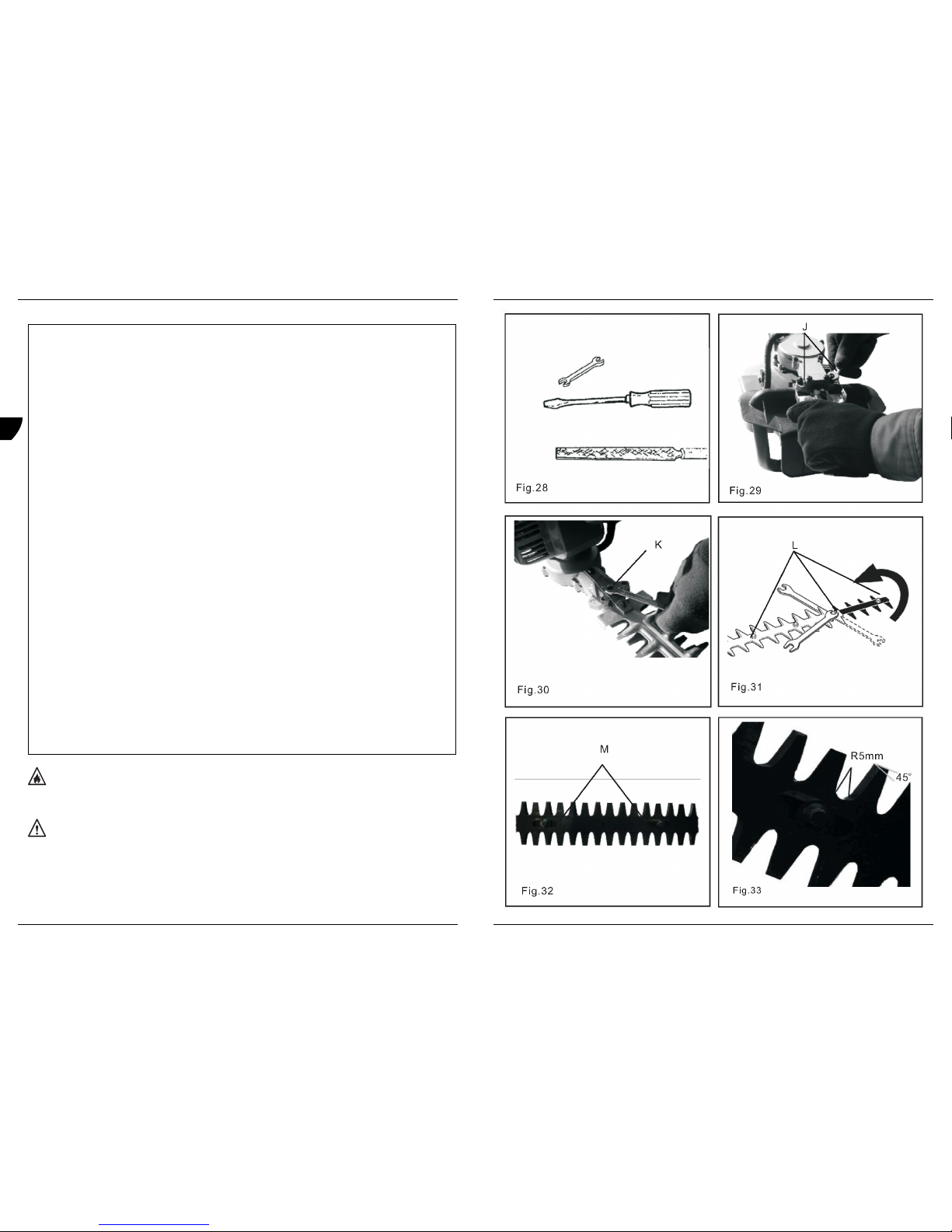
Sharpening blades (Level 3)
Fig. 28 - 33
Tools required:
2 Spanner S8-S10
1 Flat file
1 Screwdriver
Parts required:
4 Lock nuts
Warning! Hedge trimmer blades are very sharp. Wear gloves to protect hands.
• Disconnect the spark plug wire.
• Remove the blade stiffener:
• Remove two screws (J) at the bottom of front handle guard.
• Remove three screws (K) on the supporting plate for the blade.
• Remove blade stiffener locknuts (L) and washers. Do not remove blade bolts.
• Remove the blade stiffener.
• Fix locknuts (L) and washers again onto the blade
• Slide the blades to allow file clearance using slots (M) on bottom of blade. Do not pry against cutting edges.
• File each edge carefully. Follow the original shape of the blade.
Important: If apower grinder is used do not allow the blade to overheat.
• Install the blade stiffener in the reverse order.
Note: Use new locknuts each time the blade stiffener is installed.
• Lubricate the blades (see lubrication instructions).
Important: Blades should only be removed and reinstalled by an authorised servicing address, otherwise premature wear or internal
damage can occur.
Ferm 17
GB
D
NL
F
E
P
Descrição
Fig. 1
Oaparador de sebes dispõe de autocolantes de segurança. Certifique-se de que os autocolantes são legíveis e que compreende e segue as
instruções neles indicadas.
1. Protecção da pega frontal
Oacabamento confortável e texturado dispõe de um sistema anti-derrapante para a pega frontal. A protecção impede que as mãos
entrem em contacto com as lâminas. Aprotecção dispõe de autocolantes de aviso.
2. Lâminas
Abarra de suporte da lâmina inclui lâminas duplas com movimento de vaivém. As lâminas têm duas superfícies de corte.
3. Esticador da lâmina
É montado na parte superior das lâminas e orienta omaterial que está a ser cortado para as lâminas.
4. Vela de ignição
Lança uma faísca que inflama amistura de combustível.
5. Obturador
Aalavanca de controlo do obturador localizada na parte frontal do dispositivo de limpeza do ar. Desloque a patilha do obturador para
aposição de arranque a frio para fechar o obturador para arranque a frio. Desloque a patilha do obturador para a posição "RUN”
(Marcha) para abrir oobturador.
6. Bomba
Se carregar na bomba antes de ligar omotor, o combustível do depósito é aspirado para o carburador. Carregue na bomba até
ocombustível ser visível e circular livremente na conduta de retorno do depósito de combustível. Carregue na bomba mais 4 ou 5 vezes.
7. Dispositivo de limpeza do ar
Inclui um filtro substituível.
8. Pega do motor de arranque
Puxe lentamente apega até o motor de arranque engatar e depois puxe-a rapidamente e com firmeza. Não puxe a corda totalmente
nem deixe que apega volte para trás, porque pode provocar danos ao motor de arranque.
9. Depósito de combustível
Inclui combustível e um filtro de combustível.
10. Tampa do depósito de combustível
Tapa e veda aabertura do depósito de combustível.
11. Pega traseira
Inclui ointerruptor de paragem, o bloqueio e o gatilho de aceleração.
12. Bloqueio do gatilho de aceleração
Deve carregar nesta patilha antes de carregar no gatilho de aceleração.
13. Gatilho de aceleração
Amola foi concebida para voltar à posição de ralenti depois de ser libertada. Deve carregar totalmente no bloqueio do gatilho antes do
gatilho de aceleração se mover. Durante aaceleração, carregue gradualmente no gatilho para obter a melhor técnica de
funcionamento.
14. Botão de ignição
O"botão de ignição" está situado na parte superior da pega traseira. Carregue no botão “I” para colocá-lo em marcha e carregue em
“STOP” (Parar) para parar.
15. Botão de bloqueio
Obotão de bloqueio permite bloquear a aceleração na posição de arranque do seguinte modo: com a patilha de bloqueio do gatilho de
aceleração premida, carregue no gatilho de aceleração, empurre obotão de bloqueio e depois liberte lentamente o gatilho de
aceleração e, em seguida, apatilha de bloqueio de aceleração.
16. Silenciador
Osilenciador controla o nível de ruído e a emissão de fumo do sistema de escape. Mantenha a saída de escape desobstruída de
resíduos inflamáveis.
17. Capa da lâmina
Permite tapar as lâminas durante otransporte ou armazenamento. Retire a capa da lâmina antes de utilizar o aparador de sebes.
18. Dispositivo de “bloqueio”
Puxe odispositivo de “bloqueio”, a pega pode ser rodada em vários ângulos: 45 º e 90 º no sentido oposto ao dos ponteiros do relógio
+45 º e 90 º no sentido dos ponteiros do relógio para um controlo adequado durante ofuncionamento.
2. SEGURANÇA
Símbolos de segurança e informações importantes do manual
Neste manual e no próprio equipamento encontra avisos de segurança e mensagens úteis precedidos de símbolos ou de palavras-chave.
Segue-se uma explicação desses símbolos e de palavras-chave, e do que representam para outilizador:
Importante:a mensagem fornece informações necessárias para a protecção do aparador de sebes
Nota:esta mensagem inclui sugestões de utilização, cuidado e manutenção do aparador de sebes.
Em conformidade com as normas de segurança essenciais aplicáveis das directivas europeias
Este símbolo, juntamente com as indicações aviso! e perigo! chama aatenção para uma acção ou condição que pode dar
origem alesões pessoais graves no operador ou em transeuntes.
72 Ferm
GB
D
NL
F
E
P
Page 18

APARADOR DE SEBES AGASOLINA 26 CC
Os números indicados no seguinte texto correspondem às figuras na página 2-9.
Leia e certifique-se de que compreende oconteúdo do manual antes de utilizar o equipamento. Guarde-o num local seguro para
referência futura. Inclui especificações e informações sobre funcionamento, arranque, paragem, manutenção, armazenamento
e instruções específicas de montagem para este equipamento.
Leia e certifique-se de que compreende as instruções de segurança antes de utilizar oequipamento. Guarde-o num local seguro
para referência futura. Omanual explica possíveis perigos relacionados com a utilização deste equipamento e quais as medidas
atomar para torná-lo mais seguro.
Introdução
Este produto foi concebido e fabricado para proporcionar uma duração prolongada e fiabilidade durante ofuncionamento. Leia o manual e
certifique-se de que compreende oconteúdo. Irá verificar que é fácil de utilizar e dispõe de muitas sugestões de funcionamento e
mensagens de segurança. As especificações, descrições e imagens apresentadas neste manual são tão precisas quanto possível
aquando da publicação, mas podem estar sujeitas aalterações sem aviso prévio. As imagens podem incluir equipamento e acessórios
opcionais e podem não incluir todo oequipamento padrão.
Índice
1. Características técnicas da máquina
2. Segurança
3. Funcionamento
4. Manutenção
1. CARACTERÍSTICAS TÉCNICAS DAMÁQUINA
Especificações técnicas
* Não utilize combustível que contenha álcool metílico, mais de 10% de álcool etílico ou 15% de MTBE (Éter metil tert-butílico).
Conteúdo da embalagem
Depois de abrir aembalagem, verifique se algum dos componentes está danificado. Notifique de imediato o seu revendedor ou envie uma
carta com uma lista de quaisquer para amorada indicada no cartão de garantia. Utilize a lista de conteúdo para verificar as peças em falta:
1 Aparador de sebes
1 Chave emT 17 x 19
1 Chave inglesa S8-S10
1 Garrafa com mistura de combustível com óleo
1 Manual de instruções
1 Instruções de segurança
1 Cartão de garantia
Tipo de motor Refrigeração a ar, 2 tempos, um cilindro, motor a gasolina
Potência do motor 0,75 kW
Velocidade ao ralenti 2800 - 3200/min
Volume 26 cc
Diâmetro 34.0 mm
Curso 28.0 mm
Sistema de escape Silenciador
Carburador Ruixing
Sistema de ignição Ignição por volante magnético, ignição por descarga do condensador
Vela de ignição BPMR7A(Folga de 0.65 mm)
Combustível Mistura de combustível, gasolina e óleo, 25:1
Gasolina 89 octanas sem chumbo*
Óleo Óleo universal para motor a 2 tempos
Capacidade do depósito de combustível 0.6 l
Sistema de arranque Motor de arranque automático
Embraiagem Tipo centrífuga
Proporção da caixa de velocidades 58:14
Unidade de corte Lâmina dupla com movimento de vaivém, de dupla extremidade
Comprimento da lâmina 600 mm
Distância entre os dentes 27 mm
Diâmetro máximo de corte 10 mm (madeira suave)
Peso bruto 5.8 kg
Vibração pega da frente 15.08 m/s
2
Vibração pega traseira 17.75 m/s
2
Lpa (pressão do som) 95 dB (A)
Lwa (potência do som) 107 dB (A)
Ferm 71
GB
D
NL
F
E
P
Trouble shooting
Warning! Fuel vapors are extremely inflammable and can cause fire and/or explosion. Never test for ignition spark by grounding
spark plug near cylinder plug hole, otherwise serious personal injury can result.
Storage
Warning! During operation the muffler and surrounding cover become hot. Always keep exhaust area clear of inflammable debris
during transportation or when storing, otherwise serious personal injury can result.
Long Term Storage (over 30 days)
Do not store your hedge trimmer for aprolonged period of time (30 days or longer) without performing protective storage maintenance which
includes the following:
• Store hedge trimmer in adry, dust free place, out of reach of children.
Warning! Do not store in enclosure where fuel fumes can accumulate or reach anaked flame or spark, otherwise serious
personal injury can result.
Problem Check Status Cause Remedy
Engine cranks, start hard or
does not start.
Fuel at carburettor. No fuel at carburettor. Fuel strainer clogged.
Fuel line clogged.
Carburettor.
Clean or replace.
Clean or replace.
See address on the
warranty card.
Fuel at cylinder. No fuel at cylinder.
Muffler wet with fuel.
Carburettor.
Fuel mixture too rich.
See address on the
warranty card.
Open choke.
Clean or replace air filter.
Adjust carburettor.
See address on the
warranty card.
Spark at end of plug
wire.
No spark. Stop switch off.
Electrical problem.
Interlock switch.
Turn switch to on.
See address on the
warranty card.
See address on the
warranty card.
Spark at plug. No spark. Spark gap incorrect.
Covered with carbon.
Soiled with fuel.
Plug defective.
Adjust to 0.65 mm (0.026”).
Clean or replace.
Clean or replace.
Replace plug.
Engine runs, but dies or
does not accelerate
properly.
Air filter. Problem Air filter dirty. Normal wear. Clean or replace.
Fuel filter. Fuel filter dirty Contaminants or residues
in fuel.
Replace
Fuel vent. Fuel vent plugged. Contaminants or residues
in fuel.
Clean or replace.
Spark plug. Plug dirty or worn. Normal wear. Clean and adjust or
replace.
Carburettor. Incorrect adjustment. Vibration Adjust.
Cooling system. Cooling system dirty or
plugged.
Extended operation in
dusty or dirty locations.
Clean.
Engine does not crank N/A N/A Internal engine problem. See address on the
warranty card.
18 Ferm
GB
D
NL
F
E
P
Page 19

• Place the ignition switch in the “STOP” position.
• Remove accumulation of grease, oil, dirt and debris from exterior of hedge trimmer.
• Perform all periodic lubrication and services that are required.
• Apply clean oil to the entire length of the blade. Be certain the blade bolts are lubricated.
• Install blade cover on blades.
• Tighten all the screws and nuts.
• Drain the fuel tank completely and pull the recoil starter handle several times to remove fuel from the carburettor.
• Remove the spark plug and pour 7cc (1/4 oz.) of fresh, clean, two-stroke engine oil into the cylinder through the spark plug hole.
• Place aclean cloth over the spark plug hole.
• Pull the recoil starter handle 2-3 times to distribute the oil inside the engine.
• Observe the piston location through the spark plug hole. Pull the recoil handle slowly until the piston reaches the top of its travel and leave
it there.
• Install the spark plug (do not connect ignition cable).
Important: Always store and transport hedge trimmers in astable, horizontal position. Support gear case and cutting blades to prevent
excessive flexing, which can cause damage to these components. Always install the blade cover when transporting or storing hedge trimmer.
Faults
Should a fault occur, e.g. after wear of a part, please contact the service address on the warranty card. In the back of this manual you find an
exploded view showing the parts that can be ordered.
Environment
In order to avoid damage during transport, the saw is delivered in strong packaging material. Where possible, recyclable packaging material
has been used. Therefore, please recycle the packaging material.
Warranty
See the warranty card in the back of this instruction manual for the warranty terms.
CE DECLARATION OF CONFORMITY (GB)
We declare under our sole responsibility that this product is in conformity with the following standards or standardized documents:
EN10517, EN 55012, EN 61000-6-3, EN 61000-6-1
in accordance with the regulations:
98/37/EC, 89/336/EEC, 2002/88/EC, 93/68/EEC, 2000/14/EC
from 01-06-2006
ZWOLLE NL
J.A. Bakker-van Ingen J. Lodewijk
CEO Ferm BV Quality Manager Ferm Global
It is our policy to continuously improve our products and we therefore reserve the right to change the product specification without prior
notice.
Ferm BV • Lingenstraat 6 • 8028 PM Zwolle • The Netherlands
Ferm 19
GB
D
NL
F
E
P
Almacenamiento por un período prolongado (más de 30 días)
Si se prevé almacenar el cortasetos por un largo período de tiempo (30 días omás) realice el mantenimiento previo al almacenamiento que
incluye las siguientes tareas:
• Almacene el cortasetos en un lugar seco, sin polvo y fuera del alcance de los niños.
Advertencia No lo almacene en un recinto donde los gases del combustible puedan acumularse oalcanzar una chispa o llama
sin protección, de lo contrario pueden provocarse lesiones graves.
• Sitúe el interruptor de encendido en la posición “STOP”.
• Elimine la acumulación de grasa, aceite, suciedad y desechos del exterior del cortasetos.
• Realice todos los servicios y tareas de lubricación requeridas.
• Aplique el aceite limpiador alo largo de la longitud de la cuchilla. Cerciórese de que los tornillos de la cuchilla están lubricados.
• Monte la cubierta de las cuchillas.
• Apriete todos los tornillos y tuercas.
• Vacíe el depósito de combustible completamente y tire de la cuerda del motor de arranque en varias ocasiones para eliminar el
combustible del carburador.
• Desmonte la bujía y vierta 7 cm
3
(1/4 oz.) de aceite para motores de dos tiempos, nuevo y limpio en el cilindro através del orificio de la
bujía.
• Ponga un trapo limpio sobre el orificio de la bujía.
• Tire de la cuerda del motor de arranque 2 - 3 veces para distribuir el aceite en el interior del motor.
• Observe la posición del pistón através del orificio de la bujía. Tire de la cuerda lentamente hasta que el pistón alcance el tope de la
carrera y manténgalo en esa posición.
• Monte la bujía (no conecte el cable de encendido).
Importante:Transporte el cortasetos siempre en una posición horizontal y estable.
Sujete la caja de transmisión y las cuchillas para evitar una flexión excesiva que pueda dañar estos componentes. Monte siempre la cubierta
de las cuchillas durante el transporte oel almacenamiento del cortasetos.
Averías
Si se presenta una avería, por ejemplo, por el desgaste de una pieza, póngase en contacto con el proveedor de servicios indicado en la
tarjeta de garantía. En el dorso de este manual encontrará un amplio resumen de las partes de recambio que se pueden ordenar.
Uso ecológico
Para prevenir los daños durante el transporte, el aparato ha sido embalado. Dicho embalaje está hecho, en la medida de lo posible, de
material reciclable. Le rogamos, por lo tanto, que recicle dicho material.
Garantía
Lea atentamente las condiciones de garantía indicadas en la tarjeta de garantía que aparece en este manual de instrucciones.
CE DECLARACIÓN DE CONFORMIDAD (E)
Declaramos bajo nuestra exclusiva responsabilidad que este producto cumple con las siguientes normas o documentos normalizados:
EN10517, EN 55012, EN 61000-6-3, EN 61000-6-1
según las regulaciones:
98/37/EC, 89/336/EEC, 2002/88/EC, 93/68/EEC, 2000/14/EC
Del 01-06-2006
ZWOLLE NL
J.A. Bakker - van Ingen J. Lodewijk
CEO Ferm BV Quality Manager Ferm Global
Es nuestra política mejorar continuamente nuestros productos y por tanto nos reservamos el derecho a cambiar las características del
producto sin previo aviso.
Ferm BV • Lingenstraat 6 • 8028 PM Zwolle • Holanda
70 Ferm
GB
D
NL
F
E
P
Page 20

Localización de averías
¡Advertencia! Los vapores del combustible son altamente inflamables y pueden provocar un incendio ouna explosión. Nunca
pruebe el encendido de la bujía haciendo masa con la bujía cerca del orificio de la bujía del cilindro, de lo contrario puede sufrir
lesiones graves.
Almacenamiento
¡Advertencia! El silenciador y el revestimiento que lo cubre alcanzan altas temperaturas durante el funcionamiento. Mantenga la
zona del sistema de escape libre de desechos inflamables durante el transporte oel almacenamiento, de lo contrario se pueden
provocar lesiones graves.
Problema Verificar Estado Causa Solución
El cigüeñal gira, arranca
con dificultad o no
arranca.
Combustible en el
carburador.
No hay combustible en
el carburador.
Filtro de combustible
obstruido.
Tubo de combustible
obstruido.
Limpiar o sustituir.
Limpiar o sustituir.
Carburador. Ver la dirección en la tarjeta de
garantía.
Combustible en el
cilindro.
No hay combustible en
el cilindro.
Carburador. Ver la dirección en la tarjeta de
garantía.
Silenciador mojado de
combustible.
Mezcla de combustible muy
rica.
Abrir estárter.
Limpiar o sustituir el filtro de aire.
Ajustar el carburador.
Ver la dirección en la tarjeta de
garantía.
Chispa en el
extremo del cable
de la bujía.
No hay chispa. Interruptor de parada en
OFF.
Poner el interruptor en On.
Problema eléctrico. Ver la dirección en la tarjeta de
garantía.
Interruptor de bloqueo. Ver la dirección en la tarjeta de
garantía.
Chispa en la bujía. No hay chispa. Separación incorrecta del
electrodo de la bujía.
Ajustar a 0.65 mm (0.026”).
Carbonilla. Limpiar o sustituir.
Sucia de combustible. Limpiar o sustituir.
Bujía defectuosa. Sustituir bujía.
El motor gira, pero se
ahoga o no acelera
apropiadamente.
Filtro de aire. Filtro del aire sucio. Desgaste normal. Limpiar o sustituir.
Filtro de
combustible.
Filtro de combustible
sucio.
Contaminantes o residuos
en el combustible.
Sustituir.
Respiradero de
combustible.
Respiradero de
combustible obstruido.
Contaminantes o residuos
en el combustible.
Limpiar o sustituir.
Bujía Bujía sucia o
desgastada.
Desgaste normal. Limpiar y ajustar o sustituir.
Carburador Ajuste incorrecto. Vibración Ajustar.
Sistema de
refrigeración.
Sistema de refrigeración
sucio o obstruido.
Funcionamiento
prolongado en lugares
polvorientos o sucios.
Limpiar.
El cigüeñal no gira N/A N/A Problema interno del motor. Ver la dirección en la tarjeta de
garantía.
Ferm 69
GB
D
NL
F
E
P
BENZIN-HECKENSCHERE 26CC
Die Nummern im nachfolgenden Text korrespondieren mit den Abbildungen auf Seite 2 - 9.
Lesen und verstehen Sie dieses Handbuch vor dem Einsatz der Heckenschere und bewahren Sie es an einem sicheren Ort auf.
Das Handbuch enthält Angaben und Informationen über Betrieb, Ein- und Ausschalten, Wartung, Lagerung und
produktspezifisches Zubehör.
Lesen und verstehen Sie die Sicherheitshinweise vor dem Einsatz der Heckenschere und bewahren Sie sie an einem sicheren
Ort auf. In den Sicherheitshinweisen sind mögliche Gefahren, die vom Produkt ausgehen, sowie Maßnahmen für einen sicheren
Einsatz des Produkts erläutert.
Einführung
Dieses Produkt wurde für lange Lebensdauer und äußerste Zuverlässigkeit konzipiert. Lesen und verstehen Sie dieses Handbuch. Das
Handbuch ist einfach aufgebaut und enthält viele nützliche Tipps für den Betrieb sowie Sicherheitshinweise.
Die technischen Daten, Beschreibungen und Abbildungen im Handbuch entsprechen dem Stand zum Zeitpunkt der Veröffentlichung; sie
können ohne Ankündigung geändert werden.
Auf Abbildungen können auch Optionen und Zubehörteile und möglicherweise nicht alle Standardzubehörteile abgebildet sein.
Inhalt
1. Maschinendaten
2. Sicherheit
3. Betrieb
4. Wartung
1. MASCHINENDATEN
Technische Daten
* Keinen Kraftstoff mit Methylalkohol oder mehr als 10 % Ethylalkohol bzw. 15 % MTBE verwenden.
Packungsinhalt
Bitte den Packungsinhalt nach dem Öffnen auf eventuelle Beschädigungen prüfen.
Reklamieren Sie Beschädigungen oder fehlende Teile bei Ihrem Verkäufer oder bei der auf der Garantiekarte angegebenen
Serviceadresse. Verwenden Sie hierzu die Inhaltsliste:
1 Heckenschere
1 Zündkerzenschlüssel 17 x 19
1 Schlüssel S8-S10
1 Kraftstoffmischflasche
1 Bedienungshandbuch
1 Sicherheitshinweise
1 Garantiekarte
Motorentyp Lüftgekühlter Zweitakt-Einzylinder- Benzinmotor
Motorenleistung 0,75 kW
Leerlaufdrehzahl 2800-3200 U/min-1
Hubraum 26 cm
3
Bohrung 34.0 mm
Hub 28.0 mm
Abgassystem Auspufftopf
Vergaser Ruixing
Zündsystem Schwungrad-Magnet, Kondensatorentladungszündung
Zündkerze BPMR7A (Spalt 0.65 mm)
Kraftstoff Benzin-Öl-Gemisch25:1
Benzin 89 Oktan bleifrei *
Öl Universal-Zweitaktmotorenöl
Kraftstofftankinhalt 0.6 l
Anlasssystem Automatik-Ziehstarter
Kupplung Fliehkraftkupplung
Untersetzungsverhältnis 58:14
Schneidsystem Herbewegung doppelreihige Messer mit Hin- und mit doppelter Schneidkante
Messerlänge 600 mm
Teilung 27 mm
Maximaler Schnittdurchmesser 10 mm (weiches Holz)
Trockengewicht 5.8 kg
Vibration Vorderer Griff 15.08 m/s
2
Vibration Hinterer Griff 17.75 m/s
2
Schalldruckpegel (Lpa) 95 dB (A)
Schalldruckpegel (Lwa) 107 dB (A)
20 Ferm
GB
D
NL
F
E
P
Page 21

Beschreibung
Abb. 1
Prüfen Sie die Sicherheitsaufkleber auf Ihrer Heckenschere. Stellen Sie sicher, dass die Aufkleber lesbar sind und dass Sie die auf ihnen
enthaltenen Hinweise verstehen. Befolgen Sie diese. Ist ein Aufkleber nicht lesbar, können Sie bei der auf der Garantiekarte angegebenen
Serviceadresse einen neuen Aufkleber bestellen.
1. Frontgriffschutz
Komfortabler, rutschfester und modellierter Schutz am Frontgriff. Er schützt die Hände vor den Messern. Am Schutz befinden sich
Warnaufkleber.
2. Messer
Auf einen Messerbalken montierte doppelreihige Messer, die eine Hin- und Herbewegung ausführen. Die Messer besitzen zwei
Schneidkanten und können daher beidseitig schneiden.
3. Stabilisierungsschiene
Wird vorne am Messerbalken montiert und führt das zu schneidende Strauchwerk den Messern zu.
4. Zündkerze
Liefert den Funken, der das Kraftstoffgemisch zündet.
5. Choke
Der Choke-Hebel befindet sich vorne am Luftfiltergehäuse. Stellen Sie den Choke-Hebel auf die Position „Cold start“ (Kaltstart), um den
Choke für den Kaltstart zu schließen.
Geöffnet ist der Choke dagegen auf der Position „Run“ (Betrieb).
6. Startbenzinflasche
Indem Sie vor dem Starten des Motors an der Startbenzinflasche pumpen, wird Kraftstoff aus dem Kraftstofftank zum Starten in den
Vergaser gepumpt. Füllen Sie die Flasche, bis Kraftstoff in ihr zu sehen ist und ungehindert in die durchsichtige Rücklaufleitung fließt.
Pumpen Sie anschließend weitere 4 oder 5 Mal.
7. Luftfilter
Enthält ein auswechselbares Filterelement.
8. Ziehstartergriff
Ziehen Sie langsam am Ziehstarter, bis der Startermechanismus im Eingriff ist, dann schnell und kräftig anziehen. Ziehen Sie das Seil
nicht ganz heraus und lassen Sie den Griff nicht zurückschnellen, hierdurch könnte der Starter beschädigt werden.
9. Kraftstofftank
Enthält den Kraftstoff und den Kraftstofffilter.
10. Kraftstofftankdeckel
Verschließt den Kraftstofftank dicht.
11. Hinterer Griff
Hier befinden sich Stopp-Schalter, Gasgriffverriegelung und Gasgriff.
12. Gasgriffverriegelung
Dieser Hebel muss gedrückt werden, bevor der Gasgriff betätigt werden kann.
13. Gasgriff
Wird der federbelastete Gasgriff losgelassen, kehrt der Motor in die Leerlaufdrehzahl zurück. Der Hebel der Gasgriffverriegelung muss
vollständig gedrückt werden, ansonsten lässt sich der Gasgriff nicht betätigen. Beim Beschleunigen den Gasgriff langsam betätigen, bis
die geeignete Drehzahl erreicht ist.
14. Zündschalter
„Zündschalter“ oben auf dem hinteren Griff. Die Stellung „I“ entspricht Ein; die Stellung „STOP“ entspricht „Aus“.
15. Verriegelung
Die Verriegelung verriegelt den Gasgriff wie folgt in der Startstellung: Bei gedrückter Gasgriffverriegelung den Gasgriff drücken und
dann die Verriegelung betätigen; nun zuerst den Gasgriff und anschließend die Gasgriffverriegelung langsam loslassen.
16. Auspufftopf
Der Auspufftopf kontrolliert Abgasgeräusche und Emissionen. Der Abgasbereich muss stets frei von entflammbaren Substanzen sein.
17. Messerabdeckung
Hiermit werden die Messer während dem Transport oder der Lagerung abgedeckt. Vor der Benutzung der Heckenschere die
Abdeckung abnehmen.
18. „Sperr“-Schalter
Den „Sperr“-Schalter ziehen; nun lässt sich der Griff um verschiedene Winkel drehen: 45° bzw. 90° gegen den Uhrzeigersinn und 45º
bzw. 90º im Uhrzeigersinn; dies ermöglicht ein besseres Greifen bei der Arbeit.
2. SICHERHEIT
Im Handbuch verwendete Sicherheitssymbole und wichtige Informationen
In diesem Handbuch und auf dem Produkt finden Sie Sicherheitshinweise und wichtige Informationen, denen Symbole oder Signalwörter
vorangestellt sind. Die Bedeutung dieser Symbole und Signalwörter ist nachstehend erläutert:
Wichtig:Dieser Hinweis enthält wichtige Informationen für den Schutz der Heckenschere.
Hinweis:Dieser Hinweis enthält Tipps für Einsatz, Pflege und Wartung der Heckenschere.
Übereinstimmung mit den jeweils maßgeblichen EU-Sicherheitsrichtlinien
Ferm 21
GB
D
NL
F
E
P
Piezas necesarias:
4 tuercas de retención
¡Advertencia! Las cuchillas del cortasetos están muy afiladas. Utilice guantes de protección.
• Desconecte el cable de bujía.
• Desmonte el refuerzo de la cuchilla:
• Afloje los dos tornillos (J) de la parte inferior de la protección del mango.
• Afloje los tres tornillos (K) de la placa soporte de la cuchilla.
• Afloje las tuercas de retención (L) del refuerzo de la cuchilla y las arandelas. No afloje los tornillos de la cuchilla.
• Desmonte el refuerzo de la cuchilla.
• Vuelva aapretar las tuercas de retención (L) y las arandelas de la cuchilla
• Desplace las cuchillas para poder limar utilizando las ranuras (M) de la parte inferior de la cuchilla. No haga palanca contra los filos de
corte.
• Lime ambos filos cuidadosamente. Siga la forma original de la cuchilla.
Importante: Si utiliza un afilador amotor, no permita que la cuchilla se recaliente.
• Monte el refuerzo de la cuchilla en el orden inverso.
Nota: Utilice tuercas de retención nuevas cada vez que monte el refuerzo de la cuchilla.
• Lubrique las cuchillas (véanse las instrucciones de lubricación).
Importante: El desmontaje y montaje de las cuchillas sólo lo realizarán los servicios técnicos autorizados, de lo contrario se provocará el
desgaste prematuro odaños internos.
68 Ferm
GB
D
NL
F
E
P
Page 22

Rodaje del motor
Los motores nuevos tendrán que hacer un rodaje mínimo de al menos dos depósitos de combustible antes de que se puedan realizar ajustes
en el carburador. Durante el rodaje aumentará la potencia del motor y las emisiones se estabilizarán. Las revoluciones del ralentí se podrán
regular según sea necesario.
Ajuste para el funcionamiento agran altura (nivel 2)
Fig. 21 +22
Herramientas necesarias
1 destornillador
1 tacómetro
Piezas necesarias
Ninguna.
El ajuste para el funcionamiento correcto (mezcla de combustible) agran altura no es necesario en este motor.
Nota :Todos los cortasetos se ponen en funcionamiento en fábrica y el carburador se ajusta conforme a las normas de emisiones. No es
necesario el ajuste de la aceleración y de la velocidad máxima del carburador.
Compruebe las revoluciones del régimen aralentí y restablezca el ajuste de fábrica si fuera necesario. Si dispone de un tacómetro, se debe
ajustar el tornillo del régimen aralentí (H) a las especificaciones que figuran en el apartado de las especificaciones de este manual. Gire el
tornillo del ralentí (H) en el sentido de las agujas del reloj para aumentar las revoluciones del ralentí; en el sentido opuesto al de las agujas del
reloj para reducir las revoluciones del ralentí.
Advertencia Cuando se haya completado el ajuste del carburador, el accesorio de corte no se ha de mover estando el motor al
ralentí, de lo contrario se pueden provocar lesiones graves.
Lubricación de las cuchillas (nivel 1)
Fig. 23 - 25
Herramientas necesarias:
1 trapo de limpieza
1 cepillo, 25mm o 50 mm (1” o 2”)
Piezas necesarias:
1 aceite de motor, 20 W (lubricación)
1 mezcla de queroseno y aceite 20W, 50-50 (limpieza).
¡Advertencia! Las cuchillas del cortasetos están muy afiladas. Utilice guantes de protección.
• Desconecte el cable de la bujía.
• Limpie con un cepillo los desechos de la cuchilla y cubra ambas caras de la cuchilla con mezcla 50-50 de limpieza.
• Deje que la mezcla actúe suavizando los restos de goma de la cuchilla y límpiela después.
• Aplique el aceite limpiador alo largo de la longitud de la cuchilla. Cerciórese de que los tornillos de la cuchilla están lubricados.
• Limpie el exceso de aceite de la cuchilla poniendo en marcha el cortasetos.
Lubricación de la caja de transmisión (nivel 1)
Fig.26 - 27
Herramientas necesarias:
1 pistola de engrase
1 trapo de limpieza
Piezas necesarias:
1 grasa, de 14 onzas oal litio
• Limpie la suciedad de los puntos de engrase (I).
• Inyecte grasa en los puntos de engrase cuidadosamente (I). No ejerza demasiada presión al inyectar la grasa. Si aplica demasiada
presión la grasa traspasará las juntas y provocará daños. Aplique 1 - 2 bombas de aceite cada 15 - 25 horas de servicio.
• Elimine la grasa sobrante del entorno de los puntos de engrase.
Afilado de las cuchillas (nivel 3)
Fig. 28 - 33
Herramientas necesarias:
2 llaves S8-S10
1 lima plana
1 destornillador
Ferm 67
GB
D
NL
F
E
P
Dieses Symbol zusammen mit den Worten „Warnung!“ und „Gefahr!“ macht auf eine Handlung oder einen Zustand aufmerksam,
die zu ernsthaften Verletzungen für den Nutzer oder in der Nähe befindliche Personen führen können.
Die in einem durchgestrichenen Kreis dargestellten Handlungen sind verboten.
Lesen und verstehen Sie das Handbuch.
Tragen Sie Schutzbrille, Gehörschutz und Kopfschutz.
Tragen Sie einen Handschutz. Bedienen Sie das Gerät beidhändig.
Tragen Sie rutschfestes Schuhwerk.
Not-Aus-Schalter.
Choke-Hebel, Position „Cold Start“ (Kaltstart) (Choke geschlossen).
Choke-Hebel, Position „Run“ (Betrieb) (Choke geöffnet).
Kraftstoff-/Ölgemisch.
Verletzungsgefahr für die Finger.
Verbrennungsgefahr.
In Kraftstoffnähe nicht rauchen.
Keine Flammen oder Funken in Kraftstoffnähe.
Zündung Ein/Aus)
Das Gerät nicht ohne anmontierten Schutz verwenden.
Nicht in der Nähe von Stromleitungen arbeiten. Die Heckenschere ist nicht gegen elektrischen Strom isoliert. Bleiben Sie
mindestens 15m von Stromquellen entfernt.
Dritte müssen mindestens 4,5m entfernt bleiben. Passen Sie beim Arbeiten auf herabfallende Objekte auf.
Persönliche Verfassung und Sicherheitsausrüstung
Warnung! Die Benutzer dieses Produkts können sich und andere verletzen, wenn die Heckenschere nicht ordnungsgemäß
eingesetzt wird und/oder Sicherheitshinweise nicht beachtet werden. Beim Einsatz der Heckenschere geeignete Kleidung und
Sicherheitsausrüstung tragen.
Körperliche Verfassung
• Ihre Reaktionsfähigkeit und Ihre körperliche Fitness sind möglicherweise eingeschränkt:
• Wenn Sie müde oder krank sind;
• Wenn Sie Medikamente einnehmen;
• Wenn Sie Alkohol oder Drogen zu sich genommen haben.
• Benutzen Sie die Heckenschere nur, wenn Sie körperlich und geistig fit sind.
Tragen Sie Schutzausrüstung
• Tragen Sie bei der Benutzung der Heckenschere stets einen Augenschutz gemäß ANSI Z87.1 oder CE-Vorschriften.
22 Ferm
GB
D
NL
F
E
P
Page 23

• Tragen Sie rutschfeste Sicherheitshandschuhe, die einen sicheren Griff gewährleisten.
Handschuhe reduzieren auch die Vibrationen, die die Maschine auf Ihre Hände übertragen.
• Tragen Sie bei der Benutzung der Heckenschere stets einen Gehörschutz gemäß CE-Vorschriften.
Tragen Sie geeignete Kleidung
• Tragen Sie eng anliegende, feste Kleidung;
• Tragen Sie lange Hosen und langärmelige Kleidung;
• Tragen Sie keine kurzen Hosen;
• Tragen Sie keine Krawatten, Schals oder Schmuck;
• Fassen Sie lange Haare mit einem Haarschutz zusammen;
• Tragen Sie schwere Schutzschuhe mit rutschfesten Sohlen;
• Tragen Sie keine Schuhe, die vorne offen sind;
• Verwenden Sie die Heckenschere nicht barfuß.
Heißes feuchtes Wetter
Schwere Schutzkleidung kann die Arbeit sehr anstrengend machen und zu einem Hitzschlag führen. Führen Sie die Arbeit deshalb eher am
frühen Morgen oder am späten Nachmittag aus, wenn es kühler ist.
Längeres Arbeiten und extreme Bedingungen
Abb. 2
Kälte und Vibrationen können bei längerer Arbeit bei bestimmten Personen zum so genannten Raynaudschen Phänomen in den Fingern
führen. Kälte und Vibrationen können dabei ein Kribbeln und Brennen mit anschließendem Blass- und Taubwerden der Finger verursachen.
Nachstehende Vorkehrungen werden empfohlen, da nicht genau bekannt ist, mit welcher Gesetzmäßigkeit dieses Phänomen eintritt.
• Halten Sie Ihren Körper, vor allem Kopf, Nacken, Füße, Fußgelenke, Hände und Handgelenke, warm.
• Sorgen Sie durch kräftige Armübungen während häufiger Arbeitspausen für eine gute Durchblutung und rauchen Sie nicht.
• Arbeiten Sie nicht zu lange am Stück. Verrichten Sie jeden Tag auch andere Tätigkeiten, bei denen Sie keine Heckenscheren oder
handgeführten Werkzeuge halten müssen.
• Wenn Sie Unwohlsein oder gerötete bzw. geschwollene Finger mit anschließendem Blass- und Taubwerden verspüren, konsultieren
Sie Ihren Arzt, bevor Sie die Finger weiterhin Kälte und Vibrationen aussetzen.
Warnung! Verwenden Sie das Gerät nicht im Haus oder in schlecht belüfteten Räumen. Die Motorenabgase enthalten giftige
Substanzen, die ernsthafte Gesundheitsschäden oder den Tod verursachen können.
Verletzungen durch Dauerbelastung
Abb. 3
Die Überbeanspruchung der Muskeln und Sehnen der Finger, Hände, Arme und Schultern kann zu Schmerzempfinden, Schwellungen,
Taubheit und Schwäche sowie zu starken Schmerzen führen. Bestimmte repetitive Handbewegungen bergen eine große Gefahr, dass
dauerbelastungsbedingte Verletzungen entstehen.
Eine Extremform einer Verletzung durch Dauerbelastung ist beispielsweise das Karpaltunnelsyndrom (KTS), das eintreten könnte, wenn Ihr
Handgelenk anschwillt und einen vitalen Nerv in dieser Zone quetscht. Auch die Langzeiteinwirkung von Vibrationen kann zum KTS führen.
Das KTS kann starke Schmerzen für Monate oder sogar Jahre verursachen.
Mit nachstehenden Maßnahmen lässt sich das Risiko von Verletzungen durch Dauerbelastung/Karpaltunnelsyndrom reduzieren:
• Vermeiden Sie Anstrengungen Ihres Handgelenks in abgewinkelter, überdehnter oder gebogener Stellung. Versuchen Sie, mit
gestrecktem Handgelenk zu arbeiten. Packen Sie stets mit der ganzen Hand und nie nur mit Daumen und Zeigefinger zu.
• Machen Sie regelmäßig Pausen, um die Repetitivität zu verringern und Ihre Hände auszuruhen.
• Reduzieren Sie Drehzahl und Kraft bei repetitiven Bewegungen.
• Machen Sie Übungen, um die Hand- und Armmuskulatur zu stärken.
• Schalten Sie sofort alle Werkzeuge aus und suchen Sie einen Arzt auf, wenn Sie Kribbeln, Taubheit oder Schmerzen in Fingern,
Händen, Armgelenken oder Armen verspüren. Je früher Verletzungen durch Dauerbelastung/Karpaltunnelsyndrom diagnostiziert
werden, desto effektiver lässt sich eine Schädigung von Nerven und Muskulatur vermeiden.
Bereiten Sie den Arbeitsbereich vor
Abb. 4
Warnen Sie in der Nähe befindliche Personen und Kollegen, wenn Sie die Arbeit mit der Heckenschere beginnen; Kinder und Tiere müssen
mindestens 15m entfernt sein.
Halten Sie die Heckenschere fest und stellen Sie sich gut hin
Abb. 4
• Halten Sie den Frontgriff und den hinteren Griff mit beiden Händen; umfassen Sie die Griffe mit Daumen und Fingern im Gegengriff.
• Sorgen Sie immer für eine gute, ausbalancierte Standposition. Stellen Sie sich nicht auf rutschige, unebene oder instabile Flächen.
Arbeiten Sie nicht in anormalen Positionen, auf Leitern oder zu weit nach vorne gebeugt.
Drehbarer Griff
Abb. 5
Die Heckenschere ist mit einem drehbaren Griff ausgerüstet, der eine gute Kontrolle bei der Arbeit gewährleistet. Der Griff kann in
verschiedenen Winkeln gedreht werden: 45º und 90º entgegen dem Uhrzeigersinn sowie 45º und 90º im Uhrzeigersinn.
Ferm 23
GB
D
NL
F
E
P
1 embudo
1 recipiente homologado para gasolina
Piezas necesarias:
1 kit de filtro de aire y de combustible
¡Advertencia! El combustible es altamente inflamable. Extreme las precauciones cuando mezcle, almacene omanipule el
combustible.
• Utilice un trapo limpio para quitar la suciedad del entorno del tapón de combustible y del depósito de combustible vacío.
• Utilice el gancho para extraer el tubo y el filtro del depósito.
• Extraiga el filtro del tubo y monte el filtro nuevo.
Bujía (nivel 2)
Fig. 13 + 14
Herramientas necesarias:
1 llaveT
1 galga de espesor
1 cepillo de metal blando
Piezas necesarias:
1 kit de puesta apunto
Importante:Utilice sólo bujías NGK BPMR7A, de lo contrario pueden producirse daños graves en el motor.
• Desmonte la bujía y compruebe si presenta suciedad, desgaste y redondeo en el centro del electrodo.
• Limpie la bujía osustitúyala. No utilice chorro de arena para limpiarla. La arena podría penetrar en el interior y dañar el motor.
• Compruebe y ajuste la separación del electrodo de la bujía curvando el electrodo exterior.
• Apriete la bujía a150 - 170 kg/cm (130 - 150 ft-lbs).
Sistema de refrigeración (nivel 2)
Fig. 15 - 20
Herramientas necesarias:
1 destornillador
1 cepillo, 25mm o 50 mm (1"o 2")
Piezas necesarias:
Ninguna si se procede con cuidado.
Importante:Para mantener las temperaturas de servicio correctas del motor, el aire refrigerante tiene que pasar libremente a través de la
zona de la aleta de refrigeración del cilindro. Esta corriente de aire disipa el calor de la combustión del motor.
El recalentamiento oel gripado del motor puede ocurrir si:
• las tomas de aire del cárter están obstruidas y evitan que el aire refrigerante llegue al cilindro.
• se acumula el polvo y la hierba en la parte exterior del cilindro. Esta acumulación aisla el motor y evita que el calor se disipe. La limpieza
de los conductos de refrigeración del cárter ode las aletas de refrigeración se considera una tarea de mantenimiento normal. Todas
las averías que se atribuyan ala falta de mantenimiento no están cubiertas por la garantía.
Si el motor sufre un recalentamiento ose gripa, realice lo siguiente:
• Desmonte el cable y el capuchón de la bujía.
• Afloje el tornillo (F) de la cubierta del cilindro.
• Afloje los tornillos de la parte inferior derecha (G) e izquierda (G) de la cubierta del cilindro.
• Extraiga la cubierta del cilindro hacia delante, tire del cable de encendido y del de apagado y póngalos aun lado.
• Monte la bujía sin apretar para que no penetre suciedad en el cilindro. Utilice un cepillo para eliminar la suciedad de las aletas de
refrigeración del cilindro.
Importante:No utilice un rascador de metal para eliminar la suciedad de las aletas de refrigeración del cilindro. Monte los componentes en
el orden inverso.
• Vuelva a montar los componentes en el orden inverso.
Nota:Al montar la cubierta del cilindro, el cable del interruptor de apagado está asentado sobre la arandela sintética.
Orificio de escape del cilindro (nivel 3)
Importante:El orificio de escape del cilindro se revisará y limpiará de carbonilla cada 3 meses o 90 horas de servicio para cumplir el intervalo
de tiempo mínimo que marcan las normas de emisiones de los motores. Por su importancia, FERM aconseja enviar el cortasetos ala
dirección que figura en la tarjeta de garantía para que se realice esta tarea de mantenimiento.
66 Ferm
GB
D
NL
F
E
P
Page 24

Tareas de mantenimiento que puede realizar usted mismo
Códigos de las tareas de mantenimiento
I = Revisar
R = Sustituir
C = Limpiar
(1) = Aplique lubricante cada 15 - 25 horas de servicio.
(2) = Revisar la cuchilla y limpiar y afilar si fuera necesario. Lubricar las cuchillas periódicamente durante la utilización.
* = Todas las recomendaciones de sustitución se basan en la detección de daños odesgaste durante la revisión.
Filtro de aire (nivel 1)
Fig. 8-10
Herramientas necesarias:
1 cepillo, 25mm o 50 mm (1” o 2”)
Piezas necesarias:
1 kit de filtro de aire y de combustible
• Cierre el estárter en la posición de “arranque en frío”. Esto evitará que la suciedad penetre en la garganta del carburador al desmontar el
filtro de aire. Limpie la suciedad acumulada en la zona del filtro de aire con el cepillo.
• Desmonte la cubierta del filtro de aire. Limpie y revise el cartucho para detectar posibles daños. Si el cartucho está empapado de
combustible y muy sucio, sustitúyalo.
• Si el cartucho puede limpiarse para volver autilizarlo, cerciórese de que:
• aún cabe en la cavidad de la cubierta del filtro de aire.
• está montado con la cara original hacia fuera.
Nota:El ajuste del carburador puede que sea necesario después de limpiar o sustituir el filtro de aire.
Filtro de combustible (nivel 1)
Fig. 11 + 12
Herramientas necesarias:
1 trozo de cable con una extremo curvado en forma de gancho de 200 - 250mm (8 - 10”)
1 trapo de limpieza
Componente /
sistema
Tarea de
mantenimiento
Nivel de
dificultad
Adiario o
antes de la
utilización
Cada vez que
se cargue el
depósito
Cada 3 meses
o 90 horas
Cada 6 meses
o 270 horas
Anualmente
o cada 600
horas
Filtro de aire Revisar/limpiar/
sustituir
1 I C - R * - -
Estárter Revisar/limpiar 2 I C - - - -
Filtro de
combustible
Revisar/sustituir 1 - - I - R *
Sistema de
combustible, fugas
Revisar/sustituir 1 I * I I - -
Sistema de
refrigeración
Revisar/limpiar 2 I C - - - -
Caja de
transmisión
Engrasar 2 I (1) - - - -
Cuchillas Revisar/limpiar 1 I C (2) - - - -
Cuerda del motor
de arranque
Revisar/limpiar 1 I C * - - - -
Bujía Revisar/limpiar 2 - - I C R * -
Tornillos,
tuercas y pernos
Revisar/apretar/
sustituir
1 I R * - - - -
Ferm 65
GB
D
NL
F
E
P
• Ziehen Sie die gelbe „Verriegelung“ heraus und drehen Sie den Griff um den gewünschten Winkel.
• Lassen Sie dann die „Verriegelung“ wieder los und drehen Sie den Griff weiter, bis er in der richtigen Stellung einrastet. Die
„Verriegelung“ kehrt automatisch wieder in ihre ursprüngliche Position zurück.
• Versichern Sie sich, dass der Griff in der neuen Stellung verriegelt ist.
Verbrennen Sie sich nicht an heißen Flächen
Der Abgasbereich muss stets frei von entflammbaren Stoffen sein. Berühren Sie diesen Bereich während und unmittelbar nach dem
Arbeiten nicht.
Warnung! Führen Sie bei laufendem Motor nie Arbeiten an den Messern durch.
Zubehörkontrolle
Warnung! Verwenden Sie nur von Ferm genehmigtes Zubehör. Nicht genehmigte Zubehörteile können zu ernsthaften
Verletzungen führen. Ferm übernimmt keine Haftung für Mängel an Schneidvorrichtungen oder Zubehörteilen, die nicht von
Ferm getestet und genehmigt wurden. Lesen Sie alle Sicherheitshinweise in diesem Handbuch und im Sicherheitshandbuch
und beachten Sie sie.
• Prüfen Sie die Heckenschere auf lose oder fehlende Muttern und Schrauben. Diese müssen festgezogen bzw. ersetzt werden.
• Prüfen Sie Kraftstoffleitungen, Tank und Vergaserbereich auf Kraftstoffleckagen.
Betreiben Sie die Heckenschere nicht, wenn dort Kraftstoff austritt.
• Prüfen Sie die Abdeckung auf Beschädigung. Stellen Sie sicher, dass die Stabilisierungsschiene gut angebracht ist. Ersetzen Sie sie,
wenn sie beschädigt ist oder fehlt.
• Prüfen Sie, dass das Schneidzubehör fest und sicher angebracht ist.
• Prüfen Sie, dass der Frontgriff, der Schultergurt oder das Schulter-Hüft-Geschirr so eingestellt sind, dass ein sicheres und bequemes
Arbeiten möglich ist. Die richtige Einstellung ist im Kapitel „Zusammenbau“ erläutert.
3 . BETRIEB
Anforderungen an den Kraftstoff
Benzin
Verwenden Sie Kraftstoff mit 89 Oktan [R+M/2] (mittlere Stufe oder höher) guter Qualität.
Benzin kann bis zu 15 % MTBE (Methyltertiärbutyläther) enthalten. Benzin, das Methylalkohol (aus Holz) enthält, ist nicht zulässig.
Zweitaktöl
Es muss Zweitakt-Motorenöl gemäß den Normen ISO-L-EGD (ISO/CD 13738) und J.A.S.O.
FC verwendet werden. Die Ferm-Marke Premium Universal-Zweitaktöl erfüllt diese Anforderungen.
Motorenprobleme durch unzureichende Schmierung, wenn kein Öl gemäß ISOL-EGD und J.A.S.O. FC wie beispielsweise Premium
verwendet wurde, führen zum Erlöschen der Garantie für den Zweitaktmotor. (Auf die Teile der Abgasanlage wird – wie in der Garantie über
die Effektivität der Abgasanlage angegeben – ungeachtet des verwendeten Zweitaktöls eine Garantie von nur zwei Jahren gegeben.)
Verhältnis des Benzin-Öl-Gemischs: 25:1
Benzin in Litern Öl in cm
3
4 160
8 320
20 800
Wichtig:Premium Universal-Zweitaktöl kann ungeachtet der in den jeweiligen Handbüchern angegebenen Mischungsverhältnisse für alle
früheren Ferm-Motoren verwendet werden.
Umgang mit Kraftstoff
Warnung! Kraftstoff ist leicht entflammbar. Deshalb ist beim Mischen, Lagern oder Handhaben äußerste Vorsicht geboten. Es
besteht die Gefahr ernsthafter Verletzungen.
• Zugelassenen Benzinkanister verwenden.
• Nicht in der Nähe von Kraftstoff rauchen.
• Flammen oder Funken in der Nähe von Kraftstoff vermeiden.
• Kraftstofftanks und -kanister können unter Druck stehen. Sie sollten daher langsam geöffnet werden, um einen Druckausgleich zu
ermöglichen.
• Nie bei heißem oder laufendem Motor Kraftstoff nachfüllen!
• Kraftstoff nie in geschlossenen Räumen, sondern immer im Freien auf gefahrenfreien Böden nachfüllen.
• Den Tank nicht überfüllen. Ausgelaufenen Kraftstoff sofort aufwischen.
• Kraftstofftank und Benzinkanister nach dem Tanken sicher verschließen.
• Eventuelle Kraftstoffleckagen prüfen. Bei Leckagen die Heckenschere nicht in Betrieb nehmen, sondern erst die Leckage beseitigen.
• Den Motor in mindestens 3m Abstand vom Nachfüllort starten.
24 Ferm
GB
D
NL
F
E
P
Page 25

Hinweise zum Mischen
• Einen zugelassenen Benzinkanister mit der Hälfte der erforderlichen Kraftstoffmenge befüllen.
• Die korrekte Menge Zweitaktöl zum Benzin hinzugeben.
• Den Kanister verschließen und Öl und Benzin durch Schütteln vermischen.
• Das restliche Benzin hinzugeben, den Kanister verschließen und erneut schütteln.
Ausgelaufener Kraftstoff ist der Hauptgrund für Kohlenwasserstoffemissionen. In einigen Ländern sind deshalb Kanister mit automatischem
Absperrhahn vorgeschrieben, um ein Austreten des Kraftstoffs zu verhindern.
Nach dem Gebrauch
Lagern Sie die Heckenschere nicht mit vollem Kraftstofftank. Es könnte Kraftstoff austreten.
Geben Sie nicht verbrauchtes Benzin wieder in einen Benzinkanister.
Aufbewahrung
Die gesetzlichen Vorschriften für die Aufbewahrung von Kraftstoff sind von Ort zu Ort unterschiedlich. Erkundigen Sie sich deshalb nach den
für Ihr Gebiet geltenden Vorschriften.
Wichtig:Stored fuel ages. Do not mix more fuel than you expect to use in thirty (30) days, ninety (90) days when a fuel stabilizer is added.
Kraftstoff sollte vorsichtshalber in einem zugelassenen, luftdichten Kanister aufbewahrt werden, der wiederum in einem gut gelüfteten, nicht
bewohnten Gebäude, weg von Flammen oder Funken aufbewahrt werden sollte.
Wichtig:Kraftstoff unterliegt einem Alterungsprozess. Mischen Sie keinen Kraftstoff an, den Sie mehr als dreißig (30) Tage bzw. neunzig
(90) Tage nach Zugabe eines Stabilisators nach dem Anmischen zu gebrauchen beabsichtigen.
Wichtig: Gelagerter Kraftstoff für Zweitaktmotoren kann sich entmischen. Schütteln Sie deshalb den Kanister sorgfältig vor jedem Einsatz.
Starten bei kaltem Motor
Abb. 6
Hinweis:Die Messerabdeckung schützt die Messer bei Transport und Lagerung. Entfernen Sie sie vor dem Einsatz der Heckenschere.
• Kraftstoff nachfüllen: Das Gerät nur mit Kraftstoff betreiben, der im Verhältnis 25:1 mit Zweitaktöl gemischt ist.
• Den Zündschalter (B) auf die Stellung „I“ (EIN-Stellung) versetzen.
• Die Startbenzinflasche mehrmals betätigen, bis Kraftstoff sichtbar ist und ungehindert in die durchsichtige Rücklaufleitung fließt.
• Den Gasgriff in der Startposition feststellen: Bei gedrückter Gasgriffverriegelung (C) den Gasgriff (D) betätigen und dann die
Verriegelung (E) drücken; nun zuerst den Gasgriff (D) und anschließend die Gasgriffverriegelung (C) langsam loslassen.
• Den Choke-Hebel auf die Stellung Cold start (Kaltstart) (geschlossen) versetzen.
• Den Ziehstartergriff schnell ziehen; wenn erste Zündungen des Motors hörbar sind, den Choke-Hebel wieder auf die Stellung „I“ (EINStellung) versetzen; dann den Ziehstartergriff erneut schnell ziehen, bis der Motor läuft.
• Nach dem Starten des Motors den Gasgriff (D) drücken, um die Gasgriffverriegelung zu lösen, dann den Motor einige Minuten lang
warmlaufen lassen.
• Nach dem Warmlaufen des Motors den Gasgriff (D) allmählich betätigen, um den Motor auf Betriebsdrehzahl zu beschleunigen.
Hinweis:Wenn der Motor mit Choke in Position „Run“ (Betrieb) nicht startet, die Anweisungen 4 bis 6 wiederholen.
Warnung! Im Leerlauf dürfen sich die Messer nicht bewegen. Bewegen sie sich, ist der Vergaser wie im Kapitel
„Vergasereinstellung“ dieses Handbuchs beschrieben einzustellen. Andernfalls erkundigen Sie sich bei der auf der
Garantiekarte angegebenen Serviceadresse. Es droht die Gefahr ernsthafter Verletzungen.
Starten bei warmem Motor
Abb. 6
Die Startprozedur ist dieselbe wie bei „kaltem Motor“, nur dass der Choke nicht geschlossen wird.
Warnung! Im Leerlauf dürfen sich die Messer nicht bewegen. Bewegen sie sich, ist der Vergaser wie im Kapitel
„Vergasereinstellung“ dieses Handbuchs beschrieben einzustellen. Andernfalls erkundigen Sie sich bei der auf der
Garantiekarte angegebenen Serviceadresse. Es droht die Gefahr ernsthafter Verletzungen.
• Den Zündschalter (B) in die Stellung „I“ (EIN-Stellung) versetzen.
• Die Startbenzinflasche mehrmals betätigen, bis Kraftstoff sichtbar ist und ungehindert in die durchsichtige Rücklaufleitung fließt.
• Den Gasgriff in der Startposition verriegeln: Bei gedrückter Gasgriffverriegelung (C) den Gasgriff (D) drücken und dann die Verriegelung
(E) betätigen; nun zuerst den Gasgriff (D) und anschließend die Gasgriffverriegelung (C) langsam loslassen.
• Den Ziehstartergriff schnell ziehen, bis der Motor läuft.
Hinweis: Wenn der Motor nicht startet, einen Kaltstart durchführen.
Ausschalten des Motors
• Den Gasgriff loslassen, so dass der Motor vor dem Ausschalten zur Leerlaufdrehzahl zurückkehren kann.
• Den Kippschalter (B) in die Position „Stop“ stellen.
• Im Notfall den Zündschalter auf die Stellung „STOP“ versetzen.
Ferm 25
GB
D
NL
F
E
P
Nota:Si el motor no se pone en marcha, siga los pasos del arranque en frío.
Detener el motor
• Deje de acelerar y espere aque el motor gire al ralentí para apagarlo.
• Sitúe el interruptor de encendido (B) en la posición “STOP”.
• En caso de emergencia sitúe directamente el interruptor de encendido en la posición “STOP”.
Advertencia Si aún así el motor no se detiene, cierre el estárter (posición de arranque en frío) para ahogar el motor. Haga reparar
el interruptor de encendido del cortasetos en la dirección que figura en la tarjeta de garantía.
Cortar setos
Fig. 7
• Sujete el cortasetos firmemente y presione el gatillo del acelerador para acelerar el motor.
• Incline la herramienta de manera que los dientes de corte estén orientados hacia el seto oarbusto e inicie el corte.
Advertencia Mantenga ambas manos sujetando el cortasetos cuando las cuchillas estén en movimiento.
Advertencia El motor seguirá girando aunque las cuchillas se detengan al quedar bloqueadas. Si esto ocurre, detenga el motor,
desconecte el cable de encendido y libere las cuchillas.
4. MANTENIMIENTO
El cortasetos ha sido diseñado para ofrecer muchas horas de servicio sin averías. Su mantenimiento periódico le ayudará aconseguir este
propósito. Si no está seguro ono posee las herramientas necesarias para llevar a cabo un mantenimiento apropiado, encargue el mismo al
servicio técnico autorizado que figura en la tarjeta de garantía. Para facilitarle la decisión ala hora de llevar a cabo las tareas de
mantenimiento usted mismo oencargarlas al servicio técnico mencionado, hemos elaborado una tabla evaluando el grado de dificultad de
dichas tareas. Si la tarea en cuestión no figura en dicha tabla, encárguela al servicio autorizado que figura en la tarjeta de garantía.
Grados oniveles de dificultad
Nivel 1 = Fácil. La mayoría de las herramientas necesarias se adjuntan en el volumen de suministro del cortasetos.
Nivel 2 = Dificultad moderada. Se necesitarán algunas herramientas especiales.
Nivel 3 = Se requiere experiencia. Se necesitarán herramientas especiales. Ferm aconseja enviar el cortasetos ala dirección que figura en
la tarjeta de garantía.
Ferm ofrece kits de mantenimiento y piezas para facilitarle las tareas de mantenimiento. Bajo cada una de las tareas que se han de realizar
figura una lista de los números de piezas que se requieren para la mismas. Diríjase ala dirección que aparece en la tarjeta de garantía para
adquirir estas piezas.
Intervalos de mantenimiento
Tareas de mantenimiento que debe realizar el servicio técnico
Componente /
sistema
Tarea de
mantenimiento
Nivel de
dificultad
Adiario o antes
de la utilización
Cada vez que
se cargue el
depósito
Cada 3 meses
o90 horas
Cada 6
meses o270
horas
Anualmente
ocada 600
horas
Orificio de escape
del cilindro
Revisar/limpiar/
quitar la carbonilla
3- -I C--
Afilar las cuchillas Revisar/limpiar 3 I (2) - - - -
64 Ferm
GB
D
NL
F
E
P
Page 26

Instrucciones para realizar la mezcla
• Llene un recipiente homologado para combustible con la mitad de la cantidad de gasolina requerida.
• Añada la cantidad correcta de aceite para motores de 2 tiempos.
• Cierre el recipiente y agítelo para mezclar la gasolina y el aceite.
• Añada el resto de la gasolina, cierre el recipiente y vuelva aagitarlo.
El combustible vertido es una importante fuente de emisión de hidrocarburos. En algunos países se requerirá el uso de recipientes con
válvulas de cierre automáticas para reducir el vertido de combustible.
Después de la utilización
No almacene el cortasetos con combustible en el depósito. El combustible puede salirse. Extraiga el combustible no utilizado y deposítelo
en un recipiente homologado para almacenar combustible.
Almacenamiento
Las leyes que regulan el almacenamiento de combustible varían en función de país. Consulte las leyes que rigen en su localidad en los
organismos oficiales competentes. Como medida de precaución se aconseja almacenar el combustible en un recipiente hermético
homologado. Almacénelo en un recinto con buena ventilación y deshabitado, lejos de llamas ochispas sin protección.
Importante:El combustible almacenado envejece. No mezcle más combustible del que crea que vaya a utilizar en un intervalo de 30 días
(90 si se ha añadido un estabilizador).
Importante:El aceite para motores de dos tiempos almacenado tiende a separarse. Antes de que cada uso agite bien el recipiente de
combustible.
Arranque con el motor frío
Fig. 6
Nota:La cubierta de la cuchilla se utiliza durante el transporte y el almacenamiento. Retire la cubierta antes de utilizar el cortasetos.
• Añada combustible: esta herramienta se utilizará siempre con combustible mezclado con aceite de motores de dos tiempos en una
proporción 25:1.
• Sitúe el interruptor de encendido (B) en la posición “I” (posición ON)
Presione la cubeta de preinyección varias veces hasta que se vea el combustible y fluya libremente en el conducto de retorno del
depósito de combustible.
• Bloquee el acelerador en la posición de arranque: con el bloqueo del gatillo del acelerador (C) presionado, presione el gatillo (D) y pulse
el botón de bloqueo (E), acontinuación suelte primero el gatillo del acelerador (D) lentamente y después el seguro (bloqueo) del
acelerador (C).
• Sitúe la palanca del estárter en la posición de arranque en frío (cerrado).
• Tire de la cuerda del motor de arranque con fuerza, cuando oiga que el motor arranca, devuelva la palanca del estárter ala posición “I”
(posición ON), acontinuación vuelva a tirar con fuerza de la cuerda del motor de arranque hasta que el motor esté en marcha.
• Una vez esté el motor en marcha, presione el gatillo del acelerador (D) para soltar el bloqueo del acelerador, y deje que el motor gire
varios minutos para que alcance la temperatura de servicio.
• Una vez el motor alcance la temperatura de servicio, presione el gatillo del acelerador (D) progresivamente para alcanzar la velocidad
de funcionamiento.
Nota:Si le moteur ne démarre pas avec l’étrangleur en position « Run » (Marche) après 5 lancers, répétez les instructions 2 à 5.
Advertencia Las cuchillas no se han de mover con el motor aralentí. Si se mueven, regule el carburador siguiendo las
instrucciones de reglaje de este manual oconsulte a la dirección que figura en la tarjeta de garantía, de lo contrario se corre el
riesgo de sufrir lesiones graves.
Una vez el motor alcance la temperatura de servicio, sujete el mango para apretar el bloqueo del gatillo del acelerador, y presione
progresivamente el gatillo del acelerador para aumentar las revoluciones del motor hasta alcanzar el régimen de servicio.
Arranque con el motor caliente
Fig. 6
El procedimiento aseguir para el arranque en caliente es el mismo que para el arranque en frío, exceptuando el que no se ha de cerrar el
estárter.
Advertencia Las cuchillas no se han de mover con el motor aralentí. Si se mueven, regule el carburador siguiendo las
instrucciones de reglaje de este manual oconsulte a la dirección que figura en la tarjeta de garantía, de lo contrario se corre el
riesgo de sufrir lesiones graves.
• Sitúe el interruptor de encendido (B) en la posición “I” (posición ON)
Presione la cubeta de preinyección varias veces hasta que se vea el combustible y fluya libremente en el conducto de retorno del
depósito de combustible.
• Bloquee el acelerador en la posición de arranque: con el bloqueo del gatillo del acelerador (C) presionado, presione el gatillo (D) y pulse
el botón de bloqueo (E), acontinuación suelte primero el gatillo del acelerador (D) lentamente y después el seguro (bloqueo) del
acelerador (C).
• Tire de la cuerda del motor de arranque con fuerza hasta que el motor se ponga en marcha.
Ferm 63
GB
D
NL
F
E
P
Warnung! Wenn sich der Motor mit Kippschalter in Position „Stop“ nicht ausschalten lässt, den Choke schließen - Position „Cold
start“ (Kaltstart) -, um den Motor abzuwürgen. Kontaktieren Sie die auf der Garantiekarte angegebene Reparaturwerkstatt,
bevor Sie die Heckenschere erneut verwenden.
Schneiden
Abb. 7
• Die Heckenschere fest halten und den Gasgriff drücken, um den Motor zu beschleunigen.
• Die Schere so halten, dass die Schneidzähne leicht zur Hecke oder zum Strauchwerk geneigt sind, und dann schneiden.
Warnung! Die Heckenschere nie loslassen, solange die Messer in Bewegung sind.
Warnung! Der Motor läuft weiter, auch wenn die Messer durch einen Fremdkörper blockiert sind. In diesem Fall den Motor
ausschalten, das Zündkabel trennen und den Fremdkörper entfernen.
4. WARTUNG
Ihre Heckenschere ist so robust konzipiert, dass sie viele Stunden lang einen störungsfreien Betrieb gewährleistet. Eine regelmäßige
Wartung ist dabei sehr hilfreich. Wenn Sie sich die Wartungsarbeiten nicht selbst zutrauen oder nicht über das erforderliche Werkzeug
verfügen, können Sie die Wartung bei der auf der Garantiekarte angegebenen Servicewerkstatt durchführen lassen. Damit Sie leichter
entscheiden können, welche Wartungsarbeiten Sie selbst durchführen können und welche gegebenenfalls nicht, wurde den
Wartungsarbeiten eine Stufe zugeordnet. Ist eine Wartungsarbeit nicht näher spezifiziert, erkundigen Sie sich bei der auf der Garantiekarte
angegebenen Reparaturwerkstatt.
Stufe der Wartungsarbeit
Stufe 1 = Leicht durchzuführen. Die meisten Werkzeuge sind in der Packung der Heckenschere enthalten.
Stufe 2 = Etwas schwieriger. Einige Spezialwerkzeuge können erforderlich sein.
Stufe 3 = Erfahrung erforderlich. Spezialwerkzeuge sind erforderlich. Ferm empfiehlt, die Wartung bei der auf der Garantiekarte
angegebenen Servicewerkstatt durchführen zu lassen.
Ferm bietet Wartungskits und Ersatzteile für eine bequeme Wartung an. Unter jeder Überschrift sind die Artikelnummern der verschiedenen
Teile für die jeweilige Arbeit angegeben. Erkundigen Sie sich bei der auf der Garantiekarte angegebenen Serviceadresse nach diesen
Teilen.
Wartungsintervalle
Wartung durch die Servicewerkstatt
Komponente/
System
Wartungsarbeit Schwierigkeits-
stufe
Täglich oder
vor Gebrauch
Bei jedem
Nachtanken
3 Monate
oder 90
Stunden
6 Monate
oder 270
Stunden
Jährlich
oder alle 600
Stunden
Auspuffschlitz am
Zylinder
Kontrollieren/
Reinigen
/Entkrusten
3--I C--
Messer
nachschleifen
Kontrollieren/
Reinigen
3 I (2) - - - -
26 Ferm
GB
D
NL
F
E
P
Page 27

Selbst durchführbare Wartungsarbeiten
Bezeichnung der Art der Wartungsarbeit
I = Kontrollieren
R = Austauschen
C = Reinigen
(1) = Alle 15 bis 25 Betriebsstunden schmieren
(2) = Messer kontrollieren und gegebenenfalls reinigen bzw. nachschleifen. Die Messer während des Einsatzes regelmäßig schmieren.
* = Alle Austauschempfehlungen richten sich danach, was Sie bei Ihrer Kontrolle auf Beschädigung oder Verschleiß feststellen.
Luftfilter (Stufe 1)
Abb. 8-10
Erforderliches Werkzeug:
1 Reinigungsbürste, 25mm oder 50 mm (1” oder 2”)
Erforderliche Teile:
1 Luft- und Kraftstofffilter-Kit
• Den Choke in die Position „Cold start“ (Kaltstart) stellen (schließen). Auf diese Weise kann bei abgenommenem Luftfilter kein Schmutz
über die Vergaseröffnung eintreten.
Vorhandenen Schmutz aus dem Filterbereich entfernen.
• Den Luftfilterdeckel abnehmen. Den Filter reinigen und auf Beschädigung prüfen. Das Filterelement austauschen, wenn es mit
Kraftstoff getränkt oder stark verschmutzt ist.
• Wenn das Element gereinigt und wieder verwendet werden kann, ist sicherzustellen:
• Dass es nach wie vor in die Aufnahme im Luftfilterdeckel passt.
• Dass es mit der Originalseite nach außen eingesetzt wird.
Komponente/
System
Wartungsarbeit
Schwierig-
keitsstufe
Täglich oder
vor Gebrauch
Bei jedem
Nachtanken
3 Monate oder
90 Stunden
6 Monate oder
270 Stunden
Jährlich oder
alle 600
Stunden
Luftfilter Kontrollieren/
Reinigen/
Austauschen
lIC-R*- -
Choke Kontrollieren/
Reinigen
2IC----
Kraftstofffilter Kontrollieren/
Austauschen
1-IR*
Kraftstoffsystem,
Kontrollieren/
Austauschen
1--
Leckagen I* l -
Kühlsystem Kontrollieren/
Reinigen
2IC----
Getriebegehäuse
Fetten 2 I(1) - - - -
Messer Kontrollieren/
Reinigen
1 IC(2) - - - -
Ziehstarterseil Kontrollieren/
Reinigen
1 IC* - - - -
Zündkerze Kontrollieren/
Reinigen
2--ICR*-
Schrauben
und Muttern
Kontrollieren/
Festziehen/
Austauschen
1IR----
Ferm 27
GB
D
NL
F
E
P
• Compruebe que el mango ha quedado bloqueado en la nueva posición.
Evite superficies calientes
Mantenga la zona del sistema de escape libre de desechos inflamables. No toque la herramienta inmediatamente después de haberla apagado.
¡Advertencia! No realice ninguna tarea de mantenimiento de la cuchilla con el motor en marcha.
Comprobación del equipo
Advertencia Utilice sólo los accesorios homologados por Ferm. La utilización de accesorios no homologados puede provocar
lesiones. Ferm no se hace responsable de las averías de los dispositivos de corte, componentes oaccesorios que no han sido
probados y homologados por sus especialistas. Lea y respete las instrucciones de seguridad que se incluyen en este manual y
en las indicaciones de seguridad.
• Compruebe que en el cortasetos no falta ninguna tuerca tornillo operno y que están correctamente apretados. Apriételos o sustitúyalos
si fuese necesario.
• Compruebe el circuito de combustible, el depósito y el entorno del carburador para detectar posibles fugas. No utilice el cortasetos si ha
detectado alguna fuga.
• Compruebe que el revestimiento no presenta daños. Asegúrese que el refuerzo de la cuchilla está montado en la posición correcta.
• Sustitúyalo si está dañado ono está montado.
• Compruebe que el accesorio de corte está fijado correctamente y que está en buenas condiciones.
• Compruebe que el refuerzo de la cuchilla no está dañado odeformado y sustitúyalo si está curvado o dañado.
3 . FUNCIONAMIENTO
Combustible
Gasolina
Utilice sólo gasolina de 89 octanos [R+M/2] (normal osuperior) de buena calidad. La gasolina no ha de contener más de 15% de MTBE
(metilterbutil éter). No está permitido el uso de gasolina que contenga alcohol metilado (madera).
Aceite de motores de dos tiempos
Se utilizará aceite de motores de dos tiempos que cumpla con las normas ISO-L-EGD (ISO/CD 13738) y J.A.S.O. FC. Los problemas que se
presenten en el motor acausa de una lubricación inapropiada por no utilizar un aceite que cumpla las normas ISO-L-EGD y J.A.S.O. FC
anulará la garantía que concede el fabricante al motor de dos tiempos. (Los componentes relacionados con el sistema de escape sólo tienen
una garantía de dos años, independientemente del aceite de dos tiempos usado, según la declaración que figura en la aclaración de la
garantía de defectos de emisiones de escape.)
Proporción de la mezcla de combustible y aceite 25:1
Gasolina en litros Aceite en cm
3
4 160
8 320
20 800
Importante:En los antiguos motores Ferm se podrá utilizar aceite universal de calidad superior para motores de 2 tiempos en la proporción
indicada en la tabla de mezclas del manual
Manipulación del combustible
¡Advertencia! El combustible es altamente inflamable. Extreme las precauciones cuando mezcle, almacene omanipule el
combustible para evitar lesiones graves.
• Utilice un recipiente homologado para el combustible.
• No fume en las inmediaciones del combustible.
• Prohíba que se enciendan llamas ose produzcan chispas en las inmediaciones del combustible.
• En el interior de los depósitos olatas de combustible puede haberse generado presión. Abra siempre el tapón de los depósitos de
combustible lentamente para compensar la presión.
• No añada combustible al cortasetos si está el motor aún caliente oen marcha.
• No llene el depósito de combustible en recintos cerrados. Hágalo en el exterior al aire libre.
• No rebose el depósito de combustible. Limpie inmediatamente el combustible vertido.
• Apriete correctamente el tapón del depósito y cierre el depósito de combustible después de repostar.
• Compruebe si hay alguna fuga de combustible. Si detecta alguna, no ponga en marcha ni utilice el cortasetos hasta que se haya
reparado la fuga.
• Aléjese al menos 3m (10 ft.) del lugar donde añadió el combustible para poner el motor en marcha.
62 Ferm
GB
D
NL
F
E
P
Page 28

Lleve ropa de trabajo adecuada
• Lleve ropa resistente y que no le quede suelta;
• Los pantalones han de ser largos y las camisas de manga larga.
• No lleve pantalón corto.
• No lleve corbata, bufandas (pañuelo) ojoyas.
• Lleve el pelo cubierto orecogido si lo tiene largo.
• Lleve calzado de trabajo resistente y de suela antideslizante;
• No lleve calzado abierto;
• No utilice el cortasetos descalzo.
Clima caluroso y húmedo
El llevar la ropa de seguridad puede aumentar la fatiga del usuario y ser la causa de una insolación. Programe el trabajo duro para las horas
de la mañana ode la tarde cuando la temperatura es más fresca.
Utilización prolongada y condiciones extremas
Fig. 2
Se cree que un fenómeno denominado Raynaud, que afecta alos dedos de algunas personas, puede estar causado por exposición
avibraciones o al frío. La exposición a vibraciones y al frío puede causar el hormigueo y la sensación de ardor, seguido de la pérdida de color
y el entumecimiento de los dedos. Se recomiendan encarecidamente las siguientes precauciones, ya que se desconoce el grado de
exposición mínima que provoca dicha dolencia.
• Mantenga su cuerpo abrigado, especialmente la cabeza, el cuello, los pies, los tobillos, las manos y las muñecas.
• Procure que su circulación sanguínea sea buena, realice para ello numerosas pausas haciendo ejercicios enérgicos con los brazos y evite fumar.
• No realice jornadas de trabajo prolongadas con el cortasetos. Intente realizar otros trabajos cada día en los que no se requiera mantener
con las manos herramientas amotor como el cortasetos.
• Si experimenta malestar, rojez ohinchazón en los dedos, seguido de la pérdida del color o de la sensibilidad, consulte a su médico antes
de volver someterse alas vibraciones y al frío.
Advertencia No utilice esta herramienta en el interior de recintos oen lugares mal ventilados. Los gases de escape del motor son
tóxicos y pueden causar lesiones graves e incluso la muerte.
Lesiones por estrés repetitivo
Fig. 3
Se cree que el abuso excesivo de los músculos y los tendones de los dedos, manos, brazos y hombros causa dolores, hinchazón,
entumecimiento, debilidad y afecciones extremas en estos miembros. Ciertas actividades manuales repetitivas pueden exponerle al riesgo
de desarrollar una lesión por estrés repetitivo.
Una condición extrema de lesión por estrés repetitivo es el síndrome del túnel carpiano (CTS), que se produce cuando se hincha la muñeca y
comprime un nervio vital que pasa por ese área. Algunos creen que la exposición prolongada avibraciones puede contribuir al síndrome del
túnel carpiano. Este síndrome puede causar considerables dolores durante meses e incluso años.
Para reducir el riesgo de padecer una lesión de estrés repetitivo oel síndrome del túnel carpiano, realice lo siguiente:
• Evite utilizar la muñeca en una posición curvada, extendida otorcida. Intente mantener la muñeca en una posición recta. Cuando tenga
que sujetar algo, utilice toda la mano, y no sólo el pulgar y el dedo índice.
• Haga pausas periódicamente para reducir al mínimo la repetición y descansar las manos.
• Reduzca la velocidad y la fuerza con la que realiza los movimientos repetitivos.
• Realice ejercicios para fortalecer las manos y los músculos del brazo.
• Deje inmediatamente de utilizar este tipo de herramientas amotor y consulte a su médico, si siente hormigueo, entumecimiento o dolor
en los dedos, manos, muñecas obrazos. Cuanto antes se diagnostique la lesión por estrés repetitivo o el síndrome del túnel carpiano,
más probabilidades habrá de prevenir daños permanentes en nervios y músculos.
Limpieza del área de trabajo
Fig. 4
La gente ajena y los compañeros de trabajo, así como los niños y animales que se encuentren en las inmediaciones tendrán que mantener
una distancia de seguridad de al menos 15m (50 ft.) si el cortasetos está en funcionamiento.
Sujete el cortasetos con fuerza y adopte una postura firme al manejarlo
Fig. 4
• Sujete los mangos (delantero y trasero) con ambas manos, rodeándolos con los pulgares y los dedos.
• Se evitará perder el equilibrio. No trabaje sobre superficies resbaladizas, desniveladas oinestables. No trabaje sobre escaleras o en
posiciones poco convencionales. No intente cortar adistancia.
Mango rotable
Fig. 5
Para mejorar el manejo, el cortasetos está equipado con un mango rotable. El mango puede rotarse 45° y 90°, 45° en sentido contrario al de
las agujas del reloj y 90° en el sentido de las agujas del reloj.
• Extraiga el conmutador amarillo de bloqueo (A) hacia atrás y gire el mango hacia el ángulo en cuestión.
• Vuelva asoltar el conmutador de bloqueo (A) y gire el mango hasta que se escuche que encastra en la posición correcta. El conmutador
de bloqueo (A) volverá automáticamente ala posición original.
Ferm 61
GB
D
NL
F
E
P
Hinweis:Nach dem Reinigen oder Austauschen eines Luftfilters kann eine Einstellung des Vergasers erforderlich sein.
Kraftstofffilter (Stufe 1)
Abb. 11 + 12
Erforderliches Werkzeug:
1 Metalldraht mit umgebogenem Ende, Länge 200-250mm
1 Reinigungslappen
1 Trichter
1 Zugelassener Kraftstoffkanister
Erforderliche Teile:
1 Luft- und Kraftstofffilter-Kit
Warnung! Kraftstoff ist leicht entflammbar und muss deshalb sehr vorsichtig gemischt, gelagert oder gehandhabt werden.
• Schmutz am Tankdeckel mit einem Reinigungslappen entfernen und den Kraftstofftank ausleeren.
• Die Kraftstoffleitung und den Filter mit einem „Benzinleitungshaken“ aus dem Tank ziehen.
• Den Filter aus der Leitung nehmen und den neuen Filter einsetzen.
Zündkerze (Stufe 2)
Abb. 13 + 14
Erforderliches Werkzeug:
1 Zündkerzenschlüssel
1 Fühlerlehre
1 Weiche Drahtbürste
Erforderliche Teile:
1 Zündkerzen-Kit
Wichtig:Nur eine Zündkerze des Typs NGK BPMR7Averwenden, andernfalls besteht die Gefahr eines Motorschadens.
• Die Zündkerze herausschrauben und die Mittelelektrode auf Nässe, Verschleiß und Abbrand prüfen.
• Die Zündkerze reinigen oder austauschen. Nicht durch Sandstrahlen reinigen. Eventuelle Sandreste könnten den Motor beschädigen.
• Den Elektrodenspalt durch Biegen der äußeren Elektrode nachstellen.
• Die Zündkerze mit einem Drehmoment von 150-170 kgf.cm festziehen. (130 - 150 lbf.in = 14,71 - 16,67 Nm)
Kühlsystem (Stufe 2)
Abb. 15 - 20
Tools required:
Erforderliches Werkzeug:
1 Inbusschlüssel 3mm
1 Reinigungsbürste, 25mm oder 50 mm (1” oder 2”)
Erforderliche Teile:
Keine, wenn Sie vorsichtig arbeiten.
Wichtig: Damit eine effektive Motorkühlung gewährleistet ist, muss die Kühlluft frei durch die Zylinderrippen zirkulieren können. Dieser
Luftfluss führt die Verbrennungswärme vom Motor ab.
Zu einem Überhitzen und Festfressen des Motors kann es kommen, wenn:
• Die Lufteinlässe im Kurbelgehäuse versperrt sind, so dass die Kühlluft nicht an den Zylinder gelangt.
• Sich außen am Zylinder Staub und Fett abgelagert hat. Diese Ablagerungen isolieren den Motor und behindern die Wärmeabführung.
Das Entfernen solcher Ablagerungen, die die Kühlung behindern, und das Reinigen der Kühlrippen sind „Normale Wartungsarbeiten“.
Defekte infolge nicht durchgeführter Wartung sind nicht von der Garantie abgedeckt.
Bei Überhitzung und festgefressenem Motor:
• Zündkerzenstecker und Zündkerze abnehmen.
• Die Schraube (F) von der Zylinderabdeckung abnehmen.
• Die Schrauben unten rechts (G) und unten links (G) von der Zylinderabdeckung abnehmen.
• Die Schraube der Hitzeabdeckung an der Auspufftopfabdeckung abnehmen.
• Die Zylinderabdeckung vorsichtig nach vorne ziehen, so dass die Dichtung und das Zündkabel frei werden, und beiseite legen.
• Nun die Zündkerze einsetzen, ohne sie festzuziehen, damit kein Schmutz in den Zylinder eindringen kann. Die Kühlrippen sauber bürsten.
Wichtig:Die Kühlrippen des Zylinders nicht mit einem Metallschaber säubern.
• Die Komponenten in umgekehrter Reihenfolge wieder zusammenbauen.
Hinweis:Beim Montieren der Zylinderabdeckung sicherstellen, dass die Stopp-Schalter-Leitung in der Gummitülle sitzt.
28 Ferm
GB
D
NL
F
E
P
Page 29

Auspuffschlitz am Zylinder (Stufe 3)
Wichtig :Der Auspuffschlitz muss alle 3 Monate oder alle 90 Betriebsstunden kontrolliert und von Kohlerückständen gereinigt werden, damit
korrekte Emissionswerte des Motors gewährleistet sind. Ferm empfiehlt, diese wichtige Wartungsarbeit bei der auf der Garantiekarte
angegebenen Serviceadresse durchführen zu lassen.
Einfahren des Motors
Neue Motoren müssen mindestens zwei Tankfüllungen lang eingefahren werden, bevor eine Vergasereinstellung vorgenommen werden
kann. Während des Einfahrens erhöht sich die Motorleistung und die Abgasemissionen stabilisieren sich. Die Leerlaufdrehzahl kann wie
gewünscht eingestellt werden.
Einstellung der oberen Drehzahl (Stufe 2)
Abb. 21 +22
Erforderliches Werkzeug
1 Schraubendreher
1 Drehzahlmesser
Erforderliche Teile
Keine.
Eine Einstellung der oberen Drehzahl ist für den ordnungsgemäßen Betrieb dieses Motors nicht erforderlich.
Hinweis:Jede Heckenschere wird im Fertigungswerk in Betrieb genommen; dabei wird der Vergaser gemäß den
Abgasemissionsvorschriften eingestellt. Der Vergaser besitzt keine Vorrichtung zum Einstellen von Beschleunigung bzw.
Maximaldrehzahl.
Prüfen Sie die Leerlaufdrehzahl und stellen Sie diese gegebenenfalls nach. Wenn ein Drehzahlmesser verfügbar ist, sollte die
Leerlaufschraube (H) gemäß den Angaben in „Technische Daten“ dieses Handbuchs eingestellt werden. Durch Drehen der
Leerlaufschraube (H) entgegen dem Uhrzeigersinn erhöht sich die Leerlaufdrehzahl; durch Drehen im Uhrzeigersinn verringert sie sich.
Warnung! Wenn der Vergaser richtig eingestellt ist, dürfen sich die Messer bei Leerlaufdrehzahl nicht bewegen, ansonsten droht
die Gefahr einer ernsthaften Verletzung.
Schmieren der Messer (Stufe 1)
Abb. 23 - 25
Erforderliches Werkzeug:
1 Reinigungslappen
1 Reinigungsbürste, 25mm oder 50 mm (1” oder 2”)
Erforderliche Teile:
1 Motorenöl 20 W (Schmieren)
1 Gemisch aus Petroleum und Öl 20 W im Verhältnis 50:50 (Reinigen).
Warnung! Die Messer der Heckenschere sind sehr scharf. Tragen Sie deshalb stets Schutzhandschuhe.
• Das Zündkabel von der Zündkerze abziehen.
• Loses Material von den Messern abbürsten und beide Messerseiten mit dem Reinigungsgemisch im Verhältnis 50:50 reinigen.
• Klebrige Reste durch das Reinigungsgemisch aufweichen lassen und dann vom Messer abwischen.
• Sauberes Öl auf die gesamte Messerlänge auftragen. Dabei auch die Messerschrauben schmieren.
• Überschüssiges Öl von den Messern abwischen, bevor die Heckenschere wieder in Betrieb genommen wird.
Schmieren des Getriebes (Stufe 1)
Abb. 26 - 27
Erforderliches Werkzeug:
1 Fettpresse
1 Reinigungslappen
Erforderliche Teile:
1 Kleine Tube Lithiumfett
• Den Schmiernippel (1) reinigen.
• Vorsichtig Fett in den Schmiernippel (1) pressen. Das Fett nicht mit Gewalt einpressen.
Durch zu großen Druck werden Dichtungen beschädigt. Den Nippel alle 15-25 Betriebsstunden mit 1-2 Hüben abschmieren.
• Überschüssiges Fett am Schmiernippel aufnehmen.
Ferm 29
GB
D
NL
F
E
P
El círculo con la barra oblicua indica que lo que se muestra en el círculo está prohibido.
Por favor, lea detenidamente el manual para comprender las instrucciones.
Utilice gafas de seguridad y casco.
Utilice guantes de protección. Utilice ambas manos.
Utilice calzado antideslizante.
Parada de emergencia.
Control del estárter, posición “cold start” (arranque en frío, estárter cerrado).
Control del estárter, posición “run” (estárter abierto).
Mezcla de gasolina y aceite.
Peligro de amputación de los dedos.
Superficie caliente.
No fume en las inmediaciones del combustible.
Prohíba que se enciendan llamas ose produzcan chispas en las inmediaciones del combustible.
Encendido On/Off.
No utilice la herramienta con las protecciones desmontadas.
Evite el contacto con el tendido eléctrico. El cortasetos no dispone de aislamiento contra la corriente eléctrica.
Mantenga una distancia de seguridad de al menos 6m (20 ft) con respecto a fuentes de peligro eléctricas. Las personas ajenas
se mantendrán auna distancia mínima de 4,5 metros (15 feet). Prevea una "salida de emergencia" para escapar de los objetos
que puedan caer (por ejemplo, ramas).
Condición personal y equipo de seguridad
Advertencia Los usuarios de este producto corren el riesgo de lesionarse y lesionar aterceros gravemente si no utilizan el
cortasetos correctamente ono respetan las indicaciones de seguridad. Se llevará ropa de trabajo adecuada y los equipos de
seguridad al utilizar el cortasetos.
Condición física
• Su destreza física y psíquica no serán las pertinentes:
• Si está agotado oenfermo;
• Si se está medicando;
• Si está bajo la influencia de alcohol odrogas.
• Utilice el cortasetos sólo si encuentra en buenas condiciones físicas y mentales.
Lleve puestos los equipos de protección
• Lleve gafas de seguridad que cumplan la norma ANSI Z87.1 olas normas CE siempre que utilice el cortasetos.
• Lleve guantes de trabajo antideslizantes y resistentes para mejorar la adherencia alos mangos. Los guantes también reducen la
transmisión de la vibración de la máquina asus manos.
• Lleve protección para los oídos que cumplan las normas de la CE siempre que utilice el cortasetos.
60 Ferm
GB
D
NL
F
E
P
Page 30

Descripción
Fig. 1
En el cortasetos van pegados adhesivos con advertencias de seguridad. Asegúrese de que estén legibles y de que entiende y sigue las
advertencias que figuran en ellos.
1. Protección del mango delantero
Su acabado confortable y antideslizante da adherencia ala mano delantera. La protección protege las manos de las cuchillas. En la
protección van pegados adhesivos de advertencia.
2. Cuchillas
Cuchillas dobles de vaivén montadas en una barra soporte. Las cuchillas son de doble cara, capaces de cortar por ambos lados.
3. Refuerzo de la cuchilla
Sujeta la parte superior de las cuchillas y guía el material que se corta hacia las cuchillas.
4. Bujía
Produce la chispa que provoca el encendido de la mezcla de combustible.
5. Estárter
La palanca de control del estárter se encuentra en la parte delantera de la carcasa del filtro de aire. Sitúe la palanca del estárter en la
posición “cold start" (arranque en frío) para cerrar el estárter al realizar el arranque con el motor frío. Sitúe la palanca del estárter en la
posición "RUN” para abrir el estárter.
6. Cubeta del primer
Bombeando la cubeta del primer antes de arrancar el motor enviará combustible fresco del depósito, preinyectando el carburador para
el arranque. Bombee la cubeta del primer hasta que se vea el combustible y fluya libremente en el conducto transparente de retorno del
depósito de combustible. Bombee la cubeta 4 o5 veces más.
7. Filtro de aire
En el se encuentra el cartucho del filtro recambiable.
8. Asa de la cuerda del motor de arranque
Tire de la cuerda por el asa, primero lentamente hasta que note la resistencia del retroceso, y después de forma rápida y con fuerza. No
tire de la cuerda hasta extenderla en toda su longitud ono permita que el asa retroceda sin control para evitar daños en el motor de
arranque.
9. Depósito de combustible
En el se encuentran el filtro y el propio combustible.
10. Tapón del depósito de combustible
Cubre y sella la boca del depósito de combustible.
11. Mango trasero
En el se encuentran el interruptor de apagado, el bloqueo del acelerador y el gatillo del acelerador.
12. Seguro (bloqueo) del gatillo del acelerador
Este seguro ha de estar presionado para poder accionar el gatillo del acelerador.
13. Gatillo del acelerador
Muelle comprimido para volver al ralentí cuando se suelta. El seguro del gatillo ha de estar totalmente presionado antes de que el gatillo
del acelerador pueda moverse. Al acelerar, presione gradualmente para el mejor funcionamiento.
14. Interruptor de encendido
El "interruptor de encendido" está situado en la parte superior del mango trasero. Presione el interruptor “I” para la puesta en marcha y
“STOP” para detener la herramienta.
15. Botón de bloqueo
Este botón bloqueará el acelerador en la posición de arranque como sigue: con el bloqueo del gatillo del acelerador presionado,
presione el gatillo y pulse el botón de bloqueo, acontinuación suelte primero el gatillo del acelerador lentamente y después el seguro
(bloqueo) del acelerador.
16. Silenciador
El silenciador controla el ruido y las emisiones del sistema de escape. Mantenga la zona del sistema de escape libre de desechos
inflamables.
17. Cubierta de la cuchilla
Para cubrir las cuchillas durante el transporte y el almacenamiento. Retire la cubierta de las cuchillas antes de utilizar el cortasetos.
18. Interruptor de “bloqueo”
Extraiga el interruptor de “bloqueo”, el mango podrá rotarse 45º o90º, 45° en sentido contrario al de las agujas del reloj y 90º en el sentido
de las agujas del reloj, para un mejor manejo durante la utilización.
2. SEGURIDAD
Símbolos de seguridad del manual e información relevante
En el manual y en la herramienta encontrará advertencias de seguridad y consejos prácticos precedidos de símbolos opalabras clave.
Seguidamente se aclaran dichos símbolos y palabras clave:
Importante: El texto adjunto contiene información necesaria para la protección del cortasetos.
Nota :El texto adjunto contiene consejos para el uso, cuidado y mantenimiento del cortasetos.
Conforme a los estándares europeos CE aplicables en materia de seguridad.
Este símbolo en combinación con las palabras ¡Advertencia! y ¡Peligro! advierte de una operación ocondición que puede
ocasionar lesiones graves tanto al usuario como alas personas que se encuentren próximas.
Ferm 59
GB
D
NL
F
E
P
Nachschleifen der Messer (Stufe 3)
Abb. 28 - 33
Erforderliches Werkzeug:
2 Schlüssel, S8 - S10
1 Flachfeile
1 Schraubendreher
Erforderliche Teile:
4 Befestigungsmuttern
Warnung! Heckenscherenmesser sind sehr scharf. Tragen Sie deshalb stets Schutzhandschuhe.
• Den Zündkerzenstecker abklemmen.
• Die Stabilisierungsschiene abnehmen
• Zwei Schrauben (J) unten am Frontgriffschutz abnehmen.
• Drei Schrauben (K) am Messerbalken abnehmen.
• Die Befestigungsmuttern (L) und Beilagscheiben der Stabilisierungsschiene abnehmen.
• Die Messerschrauben nicht entfernen.
• Die Stabilisierungsschiene abnehmen.
• Die Befestigungsmuttern (L) und Beilagscheiben erneut am Messer befestigen.
• Die Messer mit Hilfe der Schlitze (M) an der Messerbasis so verschieben, dass Platz zum
Feilen vorhanden ist. Dabei nicht gegen die Schneidkanten drücken.
• Jede Kante vorsichtig abfeilen. Dabei der Originalform des Messers folgen.
Wichtig:Wird ein elektrisches Schleifwerkzeug verwendet, darauf achten, dass die Messer nicht zu heiß werden.
• Die Stabilisierungsschiene in umgekehrter Reihenfolge wieder anmontieren.
Wichtig:Die Messer sollten nur von einem autorisierten Servicehändler abgenommen und wieder anmontiert werden, sonst kann es zu
frühzeitigem Verschleiß oder internen Schäden kommen.
30 Ferm
GB
D
NL
F
E
P
Page 31

Störungssuche
Warnung! Kraftstoffdämpfe sind leicht entzündlich und können Feuer und/oder Explosionen verursachen. Testen Sie nie das
Vorhandensein von Zündfunken, indem Sie die Zündkerze an das Kerzenloch halten; dies könnte eine ernsthafte Verletzung zur
Folge haben.
Problem Kontrollieren Status Ursache Abhilfe
Motor dreht beim
Anlassen, startet aber
schlecht oder gar nicht.
Kraftstoff im Vergaser Kein Kraftstoff im
Vergaser
Kraftstoffsieb verstopft Reinigen oder
austauschen
Kraftstoffleitung verstopft Reinigen oder
austauschen
Vergaser Siehe Adresse auf der
Garantiekarte
Kraftstoff im Zylinder Kein Kraftstoff im Zylinder Vergaser Siehe Adresse auf der
Garantiekarte
Auspufftopf durch
Kraftstoff feucht
Kraftstoffgemisch zu fett Choke offnen Luftfilter
reinigen oder
austauschen Vergaser
einstellen Siehe Adresse
auf der Garantiekarte
Funken am
Zündkabelende
Kein Funken Stopp-Schalter aus Schalter auf On (Ein)
stellen
Elektrisches Problem Siehe Adresse auf der
Garantiekarte.
Verriegelungsschalter Siehe Adresse auf der
Garantiekarte
Funke an der Zündkerze Kein Funken Kerzenspalt falsch
eingestellt
Auf 0.65 mm einstellen
Elektrode verkohlt Reinigen oder
austauschen
Elektrode mit Kraftstoff
verunreinigt
Reinigen oder
austauschen
Zündkerze defekt Zündkerze austauschen
Motor lauft, aber stirbt
wieder ab oder
beschleunigt nicht korrekt
Luftfilter Luftfilter verschmutzt Normaler Verschleiß Reinigen oder
austauschen
Kraftstofffilter Kraftstofffilter verschmutzt Schmutz oder Reststoffe
im Kraftstoff
Austauschen
Tankentlüftung Tankentlüftung verstopft Schmutz oder Reststoffe
im Kraftstoff
Reinigen oder
austauschen
Zündkerze Zündkerze verschmutzt
oder verschlissen
Normaler Verschleiß Reinigen und einstellen
oder austauschen
Vergaser Falsche Einstellung Vibrationen Einstellen
Kühlsystem Kühlsystem verschmutzt
oder verstopft
Längerer Betrieb in
staubiger oder
schmutziger Umgebung
Reinigen
Motor dreht beim
Anlassen nicht.
NZ NZ Internes Motorproblem Siehe Adresse auf der
Garantiekarte
Ferm 31
GB
D
NL
F
E
P
CORTASETOS AGASOLINA 26 CC
Los números del texto siguiente corresponden a las ilustraciones de la página 2-9.
Lea y asegúrese de haber entendido las instrucciones de este manual antes de utilizar esta herramienta. Guarde el manual de
uso en un lugar seguro para futuras consultas. En él figuran las especificaciones e información acerca de la utilización, puesta en
marcha, parada, mantenimiento, almacenamiento y montaje de este producto.
Lea y asegúrese de haber entendido las indicaciones de seguridad antes de utilizar esta herramienta. Guarde el manual de uso
en un lugar seguro para futuras consultas. En ellas se describen los posibles peligros que conlleva la utilización de este producto
y qué medidas de seguridad habrá de tomar para que su funcionamiento sea más seguro.
Introducción
Este producto ha sido diseñado y producido para ofrecer la máxima fiabilidad en su funcionamiento y una larga vida útil . Lea y asegúrese de
haber entendido las instrucciones de este manual. Le será fácil de utilizar y en él encontrará numerosos consejos prácticos para el uso de la
herramienta, además de indicaciones de seguridad. La exactitud y actualidad de las especificaciones, descripciones y el material ilustrativo
de este manual se corresponden con el estado de la herramienta en el momento de su publicación, y está sujeto amodificaciones sin previo
aviso. Las ilustraciones pueden representar accesorios oequipos opcionales, y puede que no incluyan todo el equipamiento de serie.
Contenido
1. Datos de la máquina
2. Seguridad
3. Funcionamiento
4. Mantenimiento
1. DATOS DE LAMÁQUINA
Datos técnicos
* No utilice combustible que contenga alcohol metilado, más de 10% de alcohol etílico o15% de metilterbutil éter (MTBE) .
El embalaje contiene
Después de abrir el embalaje compruebe posibles daños. Informe inmediatamente asu distribuidor o a la dirección que figura en la tarjeta de
garantía de cualquier daño que detecte opiezas que falten. Utilice la lista del contenido para comprobar que no faltan piezas:
1 Cortasetos
1 LlaveT 17 x 19
1 Llave S8-S10
1 Botella para la mezcla de gasolina y aceite
1 Manual de instrucciones
1 Instrucciones de seguridad
1 Tarjeta de garantía
Tipo de motor Refrigerado por aire, 2 tiempos, monocilíndrico, motor de gasolina
Potencia del motor 0,75 kW
Revoluciones a ralentí 2.800 - 3.200 rpm
Cilindrada 26 cm
3
Diámetro del cilindro 34.0 mm (1,34”)
Carrera 28.0 mm (1,10”)
Sistema de escape Silenciador
Carburador Ruixing
Sistema de encendido Volante magneto, encendido por descarga del condensador
Bujía BPMR7A(separación 0.65 mm (0”,026)
Combustible Mezcla de combustible, gasolina y aceite, 25:1
Gasolina 89 octanos sin plomo *
Aceite Aceite de motores de 2 tiempos universal
Capacidad del depósito de combustible 0.6 l (20,3 onzas líqu.)
Sistema de arranque Arranque de retroceso automático (cuerda)
Embrague Centrífugo
Relación de la transmisión 58:14
Cuchilla Cuchilla doble de vaivén, de doble filo
Longitud de la cuchilla 600 mm (24”)
Pasos de los dientes 27 mm (1,06”)
Diámetro máx. de corte 10 mm (0,4”) (madera blanda)
Peso sin combustible 5.8 kg (12,3 lb.)
Vibración mango frontal 15.08 m/s
2
Vibración mango trasero 17.75 m/s
2
Lpa (presión acústica) 95dB(A)
Lwa (potencia acústica) 107 dB(A)
58 Ferm
GB
D
NL
F
E
P
Page 32

Stockage
Avertissement ! Le silencieux et/ou le catalyseur et leur couvercle peuvent devenir extrêmement chauds. Eloignez toujours
l’échappement de toute substance inflammable. Vous vous exposez sinon à de graves blessures.
Stockage longue durée (plus de 30 jours)
Ne stockez pas votre taille-haie pendant une période prolongée (plus de 30 jours) sans exécuter une maintenance préventive de stockage,
comprenant les tâches suivantes:
• Rangez le taille-haie dans un endroit sec et libre de poussière, hors de portée d’enfants.
Avertissement ! Ne stockez pas l’outil dans un endroit où des gaz de carburant pourraient s’accumuler ou atteindre une flamme
nue, faute de quoi, vous vous exposez à de graves blessures.
• Placez l’interrupteur de mise en marche/arrêt en position « OFF ».
• Éliminez toute accumulation de graisse, d’huile, de débris et de saletés du corps du taille-haie.
• Exécutez toutes les tâches de lubrification et de maintenance requises.
• Appliquez de l’huile propre sur l’ensemble de la lame. Assurez-vous que les écrous de la lame sont également lubrifiés.
• Installez le protège lame sur la lame.
• Serrez tous les écrous et boulons.
• Videz totalement le réservoir à carburant et tirez plusieurs fois sur le lanceur pour éliminer les restes de carburant du carburateur.
• Retirez la bougie et versez 7 cc d’huile deux temps fraîche dans le cylindre, à travers le trou de la bougie.
• Placez un chiffon propre sur le trou de la bougie.
• Tirez 2 à 3 fois sur le lanceur pour repartir l’huile dans le moteur.
• Observez la position du piston par le trou de la bougie. Tirez lentement sur le lanceur jusqu’à ce que le piston atteigne sa position
supérieure et laissez-le dans cette position.
• Installez la bougie (ne rebranchez pas le câble de bougie).
Important :Transportez et stockez toujours le taille-haie en position horizontale et stable.
Soutenez la transmission et la lame pour empêcher qu’elles ne fléchissent excessivement, ce qui pourrait endommager leurs composants.
Installez toujours le protège lame lorsque vous transportez ou stockez le taille-haie.
Dysfonctionnements
Veuillez vous adresser au centre de service indiqué sur la carte de garantie en cas de panne, par exemple après l'usure d'une pièce. Vous
trouverez, à la fin de ce manuel, un schéma regroupant toutes les pièces que vous pouvez commander.
Environment
Pour éviter les dommages liés au transport, la machine est livrée dans un emballage robuste.
L’emballage est autant que possible constitué de matériau recyclable. Veuillez par conséquent destiner cet emballage au recyclage.
Garantie
Pour les conditions de garantie, lisez le certificat de garantie joint à part.
CE DÉCLARATION DE CONFORMITÉ (F)
Nous déclarons sous notre seule responsabilité que ce produit est conforme aux normes standard et aux documents normalisés suivants
EN10517, EN 55012, EN 61000-6-3, EN 61000-6-1
Conformément à la réglementation.
98/37/EC, 89/336/EEC, 2002/88/EC, 93/68/EEC, 2000/14/EC
Du 01-06-2006
ZWOLLE NL
J.A. Bakker - van Ingen J. Lodewijk
CEO Ferm BV Quality Manager Ferm Global
La politique de notre société prévoit l’amélioration constante de nos produits et nous nous réservons par conséquent le droit d’en modifier les
caractéristiques techniques sans avis préalable.
Ferm BV • Lingenstraat 6 • 8028 PM Zwolle • Hollande
Ferm 57
GB
D
NL
F
E
P
Lagerung
Warnung! Während des Betriebs werden der Auspufftopf oder der Auspufftopf sowie deren Umgebung heiß. Halten Sie den
Luftaustrittsbereich während des Transports oder der Lagerung stets frei von entflammbaren Stoffen; dies könnte eine
ernsthafte Verletzung zur Folge haben.
Langzeitlagerung (länger als 30 Tage)
Wenn Sie Ihre Heckenschere für einen längeren Zeitraum (30 Tage oder länger) lagern, müssen Sie immer die vor einer Lagerung
erforderlichen, nachstehend angegebenen Wartungsschritte durchführen:
• Lagern Sie die Heckenschere an einem trockenen, staubfreien und für Kinder unzugänglichen Ort.
Warnung! Lagern Sie die Heckenschere nicht in einer Umgebung, in der sich Kraftstoffdämpfe ansammeln, die durch Flammen
oder Funken entzündet werden könnten; dies könnte eine ernsthafte Verletzung zur Folge haben.
• Stellen Sie den Stopp-Schalter auf die Position „OFF“ (AUS).
• Entfernen Sie Ansammlungen von Fett, Öl, Schmutz und Fremdkörper von der Heckenschere.
• Führen Sie alle erforderlichen regelmäßige Schmierungs- und Wartungsarbeiten durch.
• Ölen Sie die Messer auf der gesamten Länge ein. Dabei sind auch die Messerschrauben zu ölen.
• Montieren Sie die Messerabdeckung auf die Messer.
• Ziehen Sie alle Schrauben und Muttern an.
• Leeren Sie den Kraftstofftank vollständig und ziehen Sie den Startergriff mehrmals, um den Vergaser kraftstofffrei zu pumpen.
• Entfernen Sie die Zündkerze und gießen Sie 7 cm
3
frisches, sauberes Zweitaktmotorenöl durch das Kerzenloch in den Zylinder.
• Verschließen Sie das Kerzenloch mit einem sauberen Lappen.
• Ziehen Sie den Startergriff 2-3 Mal, um das Öl im Motorinneren zu verteilen.
• Beobachten Sie die Kolbenposition durch das Kerzenloch. Ziehen Sie den Startergriff langsam, bis der Kolben am oberen Totpunkt ist,
und lassen Sie ihn dort.
• Schrauben Sie die Zündkerze wieder ein (ohne den Kerzenstecker anzuschließen).
Wichtig:Lagern und transportieren Sie die Heckenschere stets in einer stabilen, waagrechten Stellung. Stützen Sie dabei das Getriebe und
den Messerbalken ab; diese könnten durch ein zu starkes Durchbiegen beschädigt werden. Bringen Sie für Transport und Lagerung der
Heckenschere stets die Messerabdeckung an.
Fehler
Sollte beispielsweise nach Abnutzung eines Teils ein Fehler auftreten, dann setzen Sie sich bitte mit der auf der Garantiekarte angegebenen
Serviceadresse in Verbindung. Im hinteren Teil dieser Anleitung befindet sich eine ausführliche Übersicht über die Teile, die bestellt werden können.
Umwelt
Um Transportschäden zu verhindern, wird die Maschine in einer soliden Verpackung geliefert. Die Verpackung besteht weitgehend aus
verwertbarem Material. Benutzen Sie also die Möglichkeit zum Recyceln der Verpackung.
Garantie
Die Garantiebedingungen finden Sie auf der lose beigefügten Garantiekarte.
CE KONFORMITÄTSERKLÄRUNG (D)
Wir erklären unsere alleinige Verantwortung, dass dieses Produkt konform den nachstehenden Standards oder standardisierten
Dokumenten ist:
EN10517, EN 55012, EN 61000-6-3, EN 61000-6-1
Gemäß den Vorschriften.
98/37/EC, 89/336/EEC, 2002/88/EC, 93/68/EEC, 2000/14/EC
vom 01-06-2006
ZWOLLE NL
J.A. Bakker - van Ingen J. Lodewijk
CEO Ferm BV Quality Manager Ferm Global
Unsere Firmenpolitik ist auf ständige Verbesserung unserer Produkte ausgerichtet und wir behalten uns das Recht vor, die
Produktspezifikation ohne vorherige Benachrichtigung zu ändern.
Ferm BV • Lingenstraat 6 • 8028 PM Zwolle • Niederlande
32 Ferm
GB
D
NL
F
E
P
Page 33

BENZINE HEGGENSCHAAR 26CC
De nummers in de nu volgende tekst verwijzen naar de afbeeldingen op pag. 2 - 9.
Lees en begrijp deze handleiding vóór gebruik. Bewaar hem op een veilige plaats om later te kunnen raadplegen. Er staan
specificaties en informatie in over gebruik, starten, stoppen, onderhoud, opslag en montage die specifiek zijn voor dit apparaat.
Lees en begrijp de veiligheidsvoorschriften vóór gebruik. Bewaar ze op een veilige plaats om later te kunnen raadplegen. Ze
leggen mogelijke gevaren, inherent aan het gebruik van dit product, uit en geven aan welke maatregelen genomen moeten
worden om dit apparaat veiliger te kunnen gebruiken.
Inleiding
Dit product is ontworpen en geproduceerd met het oog op duurzaamheid en betrouwbaarheid. Lees en begrijp deze handleiding. Hij is
gemakkelijk in het gebruik en staat vol nuttige gebruikstips en veiligheidstips. Specificaties, beschrijvingen en illustraties in dit boekje geven
nauwkeurig de stand van zaken weer ten tijde van de publicatie, maar kunnen zonder voorafgaande kennisgeving worden gewijzigd.
Illustraties kunnen extra opties en accessoires tonen, en behoeven niet de gehele standaarduitvoering te laten zien.
Inhoud
1 Gegevens van het apparaat
2. Veiligheid
3. Gebruik
4. Onderhoud
1. GEGEVENS VAN HET APPARAAT
Technische specificaties
* Gebruik geen brandstof met methylalcohol, met meer dan 10% ethylalcohol of 15% MTBE.
Inhoud verpakking
Controleer na het openen van de doos op beschadigingen. Neem direct contact op met uw leverancier of met het adres op het garantiebewijs
in geval van beschadigde of ontbrekende onderdelen. Gebruik de paklijst om te controleren of er onderdelen ontbreken:
1 Heggenschaar
1 Bougiesleutel 17 x 19
1 Moersleutel S8-S10
1 Fles om brandstof en olie te mengen
1 Handleiding
1 Veiligheidsinstructies
1 Garantiebewijs
Type motor Luchtgekoeld, tweetakt, één cilinder, benzinemotor
Motorvermogen 0,75 kW
Stationair toerental 2800 - 3200/min
Cilinderinhoud 26 cc
Boring 34.0 mm
Slag 28.0 mm
Uitlaatsysteem Geluiddemper
Carburator Ruixing
Ontstekingssysteem Vliegwiel magneetontsteking via condensator
Bougie BPMR7A(Afstand 0.65 mm)
Brandstof Mengsmering, benzine en olie, 25:1
Benzine 89 Octaan ongelood *
Olie Universeel tweetakt motorolie
Inhoud brandstoftank 0.6 L
Startsysteem Automatische starter met terugslag
Koppeling Centrifugaal type
Transmissieverhouding 58:14
Zaagbladen Dubbel heen-en-weer bewegend zaagblad met dubbel snijvlak
Lengte zaagblad 600 mm
Afstand tanden 27 mm
Max. doorsnee te zagen materiaal 10 mm (zacht hout)
Netto gewicht 5.8 kg
Trillingen voorste handvat 15.08 m/s
2
Trillingen achterste handvat 17.75 m/s
2
Lpa (geluidsdruk) 95dB (A)
Lwa (geluidsvermogen) 107 dB (A)
Ferm 33
GB
D
NL
F
E
P
Résolution des problèmes
Avertissement ! Les vapeurs de carburant sont extrêmement inflammables et peuvent provoquer des incendies et/ou des
explosions. Ne testez jamais l’étincelle d’allumage en mettant la bougie à la masse près de la cavité du cylindre. Vous risquez de
graves blessures.
Problème Vérifier État Cause Solution
Le moteur tourne,
démarre péniblement ou
ne démarre pas
Carburant au
carburateur
Pas de carburant au
carburateur
Filtre à carburant bouché Nettoyer ou remplacer
Conduite de carburant
bouchée
Nettoyer ou remplacer Reportezvous à l'adresse sur le certificat
de garantie.
Carburant au
cylindre
Pas de carburant au
cylindre
Carburateur Reportez-vous à l'adresse sur le
certificat de garantie.
Silencieux souillé de
carburant
Mélange de carburant trop
riche
Ouvrir l'étrangleur.
Nettoyer ou remplacer le filtre à
air.
Régler le carburateur.
Reportez-vous à l'adresse sur le
certificat de garantie.
Étincelle à
l'extrémité du câble
de la bougie.
Pas d'étincelle Interrupteur de mise en
marche/arrêt sur «Off»
Passer l’interrupteur sur «On»
Problème électrique Reportez-vous à l'adresse
sur le certificat de garantie.
Verrouillage de
l'accélérateur
Reportez-vous à l'adresse sur le
certificat de garantie.
Étincelle à la bougie Pas d'étincelle Écart des électrodes
incorrect
Régler à 0.65 mm (0",026)
Couverts de carbone Nettoyer ou remplacer
Encrassée de carburant Nettoyer ou remplacer
Bougie défectueuse Remplacer bougie
Le moteur tourne mais
s'éteint ou n'accélère pas
correctement
Filtre à air Filtre à air sale Usure normale Nettoyer ou remplacer
Filtre à carburant Filtre à carburant sale Contaminants ou résidus
dans le carburant
Remplacer
Purge de carburant Purge de carburant
bouchée
Contaminants ou résidus
dans le carburant
Nettoyer ou remplacer
Bougie Bougie sale ou usée Usure normale Nettoyer et régler ou remplacer
Carburateur Réglage incorrect Vibration Régler
Système de
refroidissement
Système de
refroidissement sale ou
bouché
Utilisation prolongée dans
des endroits poussiéreux ou
sales
Nettoyer
Le moteur ne tourne pas N/A N/A
Problème interne du
moteur.
Reportez-vous à l'adresse sur le
certificat de garantie.
56 Ferm
GB
D
NL
F
E
P
Page 34

Affûter la lame (Niveau 3)
Fig. 28 - 33
Outils requis :
2 Clés, S8 - S10
1 Lime plate
1 Tournevis
Composants requis :
4 Écrous
Avertissement ! La lame du taille-haie est très coupantes. Portez donc toujours des gants de protection.
• Débranchez le câble de la bougie.
• Retirez le rail de stabilisation de la lame
• Retirez les deux vis (J) sous le carter de protection de la poignée avant.
• Retirez les trois vis (K) de la plaque de coupe de la lame.
• Retirez les écrous (L) du rail de stabilisation et les rondelles. Ne retirez pas les boulons de lame.
• Retirez le rail de stabilisation
• Remontez les écrous (L) et les rondelles sur la lame.
• Faites glisser la lame dans les rainures (M) du support de lame, pour permettre le passage de la lime. Ne poussez pas sur les dents
tranchantes.
• Limez soigneusement chaque dents tranchantes. Suivez la forme originale de la lame.
Important : Si vous utilisez une meule électrique, faites attention à ce que la lame ne devienne pas trop chaude.
• Réinstallez le rail de stabilisation de la lame dans l'ordre inverse.
Important : La lame ne doit être retirée et installée que par un centre de service agréé. Dans le cas contraire, elle peut s’user prématurément
et/ou provoquer des dommages internes .
Ferm 55
GB
D
NL
F
E
P
Beschrijving
Fig. 1
Zoek de veiligheidsstickers op uw heggenschaar. Zorg ervoor dat deze stickers leesbaar zijn en dat ude instructies erop begrijpt en uitvoert.
Als een sticker niet leesbaar is, kunt ueen nieuwe bestellen bij het adres op het garantiebewijs.
1. Voorste veiligheidshandvat
Comfortabele, voorgevormde afwerking biedt een antislipgreep voor de voorste hand. De beschermplaat beschermt uw handen tegen
de zaagbladen. Waarschuwingsstickers zitten op de beschermplaat.
2. Zaagbladen
Dubbele, heen-en-weer bewegende zaagbladen, gemonteerd in een zaagbladhouder. De zaagbladen zijn tweezijdig, en kunnen aan
beide kanten zagen.
3. Zaagbladversteviger
Zit aan de bovenkant van de zaagbladen en trekt het te zagen materiaal de zaagbladen in.
4. Bougie
Levert de vonk om het brandstofmengsel te ontsteken.
5. Choke
De chokehendel zit aan de voorkant van het luchtfilterhuis. Zet de chokehendel op "Cold start" (Koude start) om de choke te sluiten voor
een koude start. Zet de chokehendel op "Run" (Open) om de choke te openen.
6. Pompbalgje
Door op het pompbalgje te drukken voordat de motor wordt gestart, wordt verse brandstof uit de brandstoftank gepompt om de
carburateur klaar te maken voor het starten. Druk op het pompbalgje tot de brandstof zichtbaar is en vrij door de lege brandstof
retourslang vloeit. Druk nogmaals 4 of 5 maal op het balgje.
7. Luchtfilter
Bevat een vervangbaar filterelement.
8. Starthendel
Trek langzaam aan de greep totdat de starter aanslaat, trek daarna snel en stevig. Trek het koord niet helemaal uit en laat de greep niet
terugspringen om mogelijke schade aan de starter te voorkomen.
9. Brandstoftank
Bevat brandstof en een brandstoffilter.
10. Dop brandstoftank
Bedekt en sluit de tankopening.
11. Achterste handvat
Bevat de stopschakelaar, het slot van de gashendel en de gashendel.
12. Slot gashendel
Deze hendel moet worden ingedrukt voordat de gashendel kan worden gebruikt.
13. Gashendel
Voorzien van een veer om terug te keren naar de stationaire stand wanneer hij wordt losgelaten. De slotschakelaar moet helemaal zijn
ingedrukt voordat de gashendel kan bewegen. Druk de gashendel bij versnellen geleidelijk in voor optimale werking.
14. Startknop
"Startknop" zit bovenaan het achterste handvat. Druk op schakelaar “I” om te starten, druk op “STOP” om te stoppen.
15. Slotknop
De slotknop zet de gashendel vast in de startstand: Druk, terwijl de slotschakelaar van de gashendel is ingedrukt, de gashendel naar
beneden en druk op de slotknop; laat dan langzaam eerst de gashendel los en vervolgens de slotknop.
16. Geluiddemper
De geluiddemper vermindert het geluid en de emissie van de uitlaat. Houd brandbaar afval uit de buurt van de uitlaat.
17. Zaagbladhoes
Wordt gebruikt om de zaagbladen te beschermen tijdens vervoer en opslag. Verwijder de zaagbladhoes voordat ude heggenschaar gebruikt.
18. “Blokkeringsschakelaar”
Door aan de “blokkeringsschakelaar” te trekken kan het handvat onder verschillende hoeken worden gedraaid: 45º en 90º linksom + 45º
en 90º rechtsom om een goed houvast te hebben tijdens het gebruik.
2. VEILIGHEID
Veiligheidspictogrammen en belangrijke informatie in deze handleiding
In deze handleiding en op het apparaat zelf treft uveiligheidswaarschuwingen en nuttige informatie aan voorafgegaan door pictogrammen of
sleutelwoorden. Het onderstaande is een uitleg van deze pictogrammen en sleutelwoorden en van wat ze voor ubetekenen:
Belangrijk:Onderstaande tekst bevat informatie voor de bescherming van de heggenschaar.r
Let op:Onderstaande tekst bevat tips voor het gebruik, de zorg en het onderhoud van de heggenschaar.
Conform de Europese toepasselijke standaards op het gebied van veiligheid
Dit pictogram vergezeld van de woorden Waarschuwing! en Gevaar! vestigt uw aandacht op een handeling of een situatie die
kan leiden tot ernstige verwondingen voor de gebruiker en de omstanders.
De cirkel met de schuine streep betekent dat wat er in de cirkel getekend is, niet is toegestaan.
34 Ferm
GB
D
NL
F
E
P
Page 35

Lees en begrijp de handleiding.
Draag oog-, gehoor- en hoofdbescherming.
Draag handbescherming. Gebruik beide handen.
Draag antislip schoeisel.
Noodstop.
Chokeknop, “Cold Start” (Koude start) stand (choke gesloten).
Chokeknop, “Run” (Open) stand (choke open).
Brandstof/olie mengsel.
Afsnijden van vingers.
Heet oppervlak.
Niet roken bij brandstof.
Zorg dat geen vlammen of vonken bij de brandstof komen.
Ontsteking Aan/Uit.
Niet gebruiken als de beschermplaten niet bevestigd zijn.
Geen elektriciteitsdraden aanraken. Deze heggenschaar is niet geïsoleerd voor elektrische stroom. Niet gebruiken op minder
dan 15 meter afstand van gevaarlijke elektrische bronnen.
Houd omstanders op ten minste 4,5 meter afstand. Plan een vluchtweg in geval van vallende voorwerpen.
Persoonlijke conditie en veiligheidsuitrusting
Waarschuwing! Gebruikers van dit product kunnen zichzelf en anderen verwonden, als de heggenschaar niet op de juiste wijze
wordt gebruikt en/of als de veiligheidsvoorschriften niet opgevolgd worden. Tijdens het gebruik van de heggenschaar moet
goede kleding en een veiligheidsuitrusting worden gedragen.
Lichamelijke conditie
• Als umoe of ziek bent;
• Als umedicijnen gebruikt;
• Als ualcohol of drugs hebt gebruikt.
• Gebruik de heggenschaar alleen als uzich lichamelijk en geestelijk goed voelt.
Draag beschermende kleding
• Draag oogbescherming die voldoet aan de ANSI Z87.1 of CE eisen wanneer ude heggenschaar gebruikt.
• Draag antislip, zware handschoenen om beter grip op het handvat te hebben. Handschoenen dempen ook de overdracht van de
motortrilling naar uw handen.
• Draag gehoorbescherming die voldoet aan de CE-eisen wanneer de heggenschaar wordt gebruikt.
Draag goede kleding
• Draag goedzittende, duurzame kleding.
• De broek moet lange pijpen hebben, overhemden lange mouwen.
Ferm 35
GB
D
NL
F
E
P
Port d’échappement du cylindre (Niveau 3)
Important :Le port d’échappement du cylindre doit être inspecté et les excès de carbone doivent être éliminés tous les 3 mois ou 90 heures de
fonctionnement afin de garantir les valeurs émises par le moteur . Ferm recommande que le taille-haie soit renvoyé à l’adresse mentionnée
sur le certificat de garantie pour que cette tâche importante de maintenance y soit réalisée.
Rodage du moteur
La consommation minimum de pleins de carburant est nécessaire au rodage des moteurs neufs avant de pouvoir effectuer un réglage du
carburateur. Le rodage permet d’améliorer la capacité du moteur et de stabiliser les émissions des gas d’échappement. La régime au ralenti
peut être réglée à souhait.
Réglage du ralenti (Niveau 2)
Fig. 21 +22
Outils requis :
1 Tournevis
1 Tachymètre
Composants requis :
Aucun.
Un réglage en fonction de l’altitude n’est pas nécessaire au bon fonctionnement de ce moteur.
Remarque :Chaque taille-haie a été essayé en usine et le carburateur est réglé en conformité avec les directives concernant l’émission des
gas d’échappement. Le carburateur ne dispose pas d’aiguille de réglage de l’accélération et de plein régime.
Vérifiez la vitesse de ralenti et réglez-la si nécessaire. Si vous disposez d’un tachymètre, la vis de réglage de ralenti (H) doit être réglée
conformément aux caractéristiques que vous trouverez dans le chapitre « Caractéristiques » du présent manuel. Tournez la vis de réglage
de ralenti (H) dans le sens des aiguilles d’une montre pour augmenter la vitesse de ralenti et inversement pour la diminuer.
Avertissement ! Lorsque le réglage du carburateur est terminé, la lame ne doit pas bouger au ralenti. Dans le cas contraire, vous
vous exposez à de graves blessures.
Lubrification de la lame (Niveau 1)
Fig. 23 - 25
Outils requis :
1 Chiffon de nettoyage
1 Brosse, 25 mm ou 50 mm (1” ou 2”)
Composants requis :
1 Huile moteur, 20 W (lubrification)
1 Mélange à base de pétrole et d’huile 20 W, 50-50 (nettoyage).
Avertissement ! La lame du taille-haie est très coupantes. Portez donc toujours des gants de protection.
• Retirez le câble de la bougie.
• Brossez les débris de la lame et appliquez le mélange 50-50 de nettoyage sur les deux côtés de la lame.
• Laissez le mélange de nettoyage dissoudre les résidus restants, puis frottez la lame.
• Appliquez de l’huile propre sur l’ensemble de la surface de la lame. Lubrifiez également les écrous de la lame.
• Éliminez le surplus d'huile sur la lame avant de réutiliser le taille-haie.
Lubrification de la transmission (Niveau 1)
Fig.26 - 27
Outils requis :
1 Pistolet à graisse
1 Chiffon de nettoyage
Composants requis :
1 Graisse, 14 oz. Base lithium
• Éliminez les débris du téton de graissage (1).
• Pompez prudemment de la graisse dans le téton de graissage (1). Ne forcez pas. Trop de pression pourrait nuire l’étanchéité. Appliquez
1 à 2 coups de pistolet de graisse toutes les 15 à 25 heures de fonctionnement.
• Nettoyez le surplus de graisse autour du téton de graissage.
54 Ferm
GB
D
NL
F
E
P
Page 36

Filtre à carburant (Niveau 1)
Fig. 11 + 12
Outils requis :
1 Un bout de fil de fer avec une extrémité repliée pour former un crochet, 200-250mm (8-10")
1 Chiffons de nettoyage
1 Entonnoir
1 Récipient approuvé pour carburant
Composants requis :
1 Kit de filtres à air et à carburant
Avertissement ! L’essence est très inflammable. Soyez extrêmement prudent lorsque vous la mélangée, stockée ou manipulée.
• Utilisez un chiffon propre pour éliminer les débris autour du bouchon du réservoir et videz le réservoir.
• Utilisez le « crochet » pour retirer le filtre à carburant et sa conduite du réservoir.
• Déconnectez le filtre de la conduite et installez le nouveau filtre.
Bougie (Niveau 2)
Fig. 13 + 14
Outils requis :
1 Clé à bougie
1 Calibre de bougies
1 Brosse métallique souple
Composants requis :
1 Kit de réglage
Important :N’utilisez que des bougies du type NGK BPMR7A, sinon vous pourriez endommager sévèrement le moteur.
• Retirez la bougie et vérifiez si elle n’est pas endommagée et si l’électrode centrale n’est pas usée ou arrondie.
• Nettoyez la bougie ou remplacez-la par une nouvelle. Ne sablez pas la bougie pour la nettoyer. Les résidus de sable pourraient
endommager le moteur.
• Ajustez l’écart entre les électrodes en pliant l’électrode externe.
• Serrez la bougie à un couple de 150-170 kg/cm. (130 - 150 inch/lb)
Système de refroidissement (Niveau 2)
Fig. 15 - 20
Outils requis :
1 Clé hexagonale 3mm
1 Brosse, 25mm ou 50 mm (1” ou 2”)
Composants requis :
Aucun, si vous êtes prudent.
Important :Pour garantir des températures appropriées de fonctionnement, l’air de refroidissement doit pouvoir circuler librement sur les
lames du cylindre. Ce débit d’air élimine la chaleur de combustion du moteur.
Le moteur peut surchauffer et se bloquer lorsque :
• Les admissions d’air du carter sont bloquées, empêchant l’air de refroidissement d’atteindre le cylindre.
• De la poussière et des débris s’accumulent sur le corps du cylindre. Ces accumulations isolent le moteur et empêchent l'évacuation de la
chaleur. L’élimination des débris des admissions du carter et le nettoyage des lames de refroidissement font partie de la « maintenance
normale ». Tout dysfonctionnement pouvant être attribué à un manque de maintenance n’est pas couvert par la garantie.
Si le moteur surchauffe et se bloque, procédez comme suit :
• Retirez le câble de la bougie et la bougie.
• Retirez les vis Allen (F) du capot du démarreur et le démarreur.
• Retirez les vis Allen inférieures de droite (G) et de gauche (G) du cache cylindre.
• Retirez l’écrou de le cache de protection thermique du carter du silencieux.
• Retirez prudemment le cache du cylindre en désengageant les joints d’étanchéité du silencieux et le câble de bougie et mettez-le de côté.
• Replacez, sans serrer, la bougie pour éviter que des débris puissent pénétrer dans le cylindre. Utilisez une brosse pour éliminer les
débris sur les lames du cylindre.
Important :N’utilisez pas d’objets métalliques pour gratter les débris sur les lames du cylindre.
• Réassemblez les composants dans l’ordre inverse.
Remarque :Lorsque vous installez le cache du cylindre, assurez-vous que le câble de l’interrupteur de mise en marche/arrêt passe dans
l'oeillet en caoutchouc.
Ferm 53
GB
D
NL
F
E
P
• Draag geen korte broek.
• Draag geen stropdas, sjaal of sieraden.
• Draag beschermende hoofdbedekking die ook lang haar bedekt.
• Draag stevige werkschoenen met antislip zolen.
• Draag geen schoenen met open tenen.
• Gebruik de heggenschaar niet op blote voeten.
Warm vochtig weer
Zware beschermende kleding kan de vermoeidheid van de gebruiker doen toenemen, wat kan leiden tot zonnesteek. Plan zwaar werk vroeg
in de ochtend of laat in de middag, wanneer het koeler is.
Langdurig gebruik en extreme omstandigheden
Fig. 2
Er wordt gezegd dat een verschijnsel dat het Fenomeen van Raynaud heet en dat de vingers van sommige mensen aantast, veroorzaakt
wordt door blootstelling aan trilling en kou. Blootstelling aan trilling en kou kan een tintelend en brandend gevoel veroorzaken, gevolgd door
bleekheid en verdoving van de vingers. De volgende voorzorgsmaatregelen worden sterk aanbevolen, omdat de minimum blootstelling, die
deze kwaal kan teweegbrengen, onbekend is.
• Houd uw lichaam warm, speciaal uw hoofd, nek, voeten, enkels, handen en polsen.
• Zorg voor een goede bloedsomloop door krachtige armoefeningen te doen tijdens regelmatige onderbreking van het werk, en door niet te roken.
• Beperk het aantal uren dat uapparatuur gebruikt. Probeer iedere dag ook taken te doen waarbij de heggenschaar of ander mechanisch
handgereedschap niet nodig is.
• Als uongemak ervaart, of rode en gezwollen vingers krijgt, gevolgd door bleekheid en verlies van gevoel, raadpleeg dan uw huisarts
voordat uzichzelf verder blootstelt aan kou en trilling.
Waarschuwing! Gebruik dit apparaat niet binnenshuis of in onvoldoende geventileerde ruimtes. De uitlaatgassen bevatten
giftige stoffen en kunnen ernstige gezondheidsklachten of de dood tot gevolg hebben.
Repetitive Stress Injuries (‘Muisarm’, RSI)
Fig. 3
Er wordt gezegd dat overmatig gebruik van de spieren en pezen van vingers, handen, armen en schouders gevoeligheid, zwelling,
verdoving, zwakte en extreme pijn in die lichaamsdelen kan veroorzaken. Sommige zich herhalende activiteiten van de hand brengen voor
uhet risico met zich mee van het ontwikkelen van Repetitive Stress Injury (RSI). Een extreme vorm van RSI is het Carpaal Tunnel Syndroom
(CTS), dat kan ontstaan als uw polsen opzwellen en zo drukken op een vitale zenuw die daar doorheen loopt. Sommigen menen dat
langdurige blootstelling aan trilling CTS kan veroorzaken. CTS kan gedurende maanden of zelfs jaren hevige pijn veroorzaken.
Om het risico van RSI/CTS te verminderen kunt uhet volgende doen:
• Gebruik uw polsen niet in een gebogen, gestrekte of gedraaide stand. Probeer in plaats daarvan uw polsen in een rechte stand te
houden. Gebruik bij grijpen uw hele hand en niet alleen uw duim en wijsvinger.
• Pauzeer regelmatig om herhaling zo klein mogelijk te maken en geef uw handen rust.
• Verminder de snelheid en de kracht waarmee uherhalende bewegingen uitvoert.
• Doe oefeningen om de hand- en armspieren te versterken.
• Stop direct met het gebruik van mechanische apparatuur en raadpleeg een arts, als utinteling, verdoving of pijn in uw vingers, handen,
polsen of armen voelt. Hoe sneller de diagnose RSI/CTS is gesteld, des te beter kan permanente beschadiging van zenuwen en spieren
worden voorkomen.
Ontruim uw werkplek
Fig. 4
Omstanders en collega’s moeten worden gewaarschuwd, en kinderen en dieren moet worden verboden dichter dan 15m in de buurt te zijn,
wanneer de heggenschaar wordt gebruikt.
Goed vasthouden en stevig staan
Fig. 4
• Houd het voorste en achterste handvat met beide handen vast, waarbij duim en wijsvinger om de handvatten zitten.
• Blijf altijd stevig en stabiel staan. Ga niet staan op gladde, oneffen of instabiele oppervlaktes. Werk niet in een ongewone positie of op
een ladder. Grijp niet boven uw macht.
Draaibaar handvat
Fig. 5
Om tijdens het gebruik een goede controle te hebben is de heggenschaar voorzien van een draaibaar handvat.
Het handvat kan onder verschillende hoeken worden gedraaid: 45º en 90º tegen de klok in, en 45º en 90º met de klok mee.
• Trek de gele “blokkerings”-schakelaar naar achteren en draai het handvat naar de gewenste hoek.
• Laat de “blokkerings”-schakelaar weer los en draai het handvat tot hij in de juiste stand klikt. De “blokkerings”-schakelaar keert
automatisch terug naar zijn oorspronkelijke stand.
• Controleer of het handvat nu in de nieuwe stand geblokkeerd is.
Vermijd hete oppervlaktes
Houd de omgeving van de uitlaat vrij van brandbaar afval. Raak de uitlaat niet aan tijdens en direct na gebruik.
36 Ferm
GB
D
NL
F
E
P
Page 37

Waarschuwing! Voer nooit onderhoud uit aan het zaagblad terwijl de motor loopt.
Controle apparatuur
Waarschuwing! Gebruik alleen door Ferm goedgekeurde hulpstukken. Ukunt ernstig gewond raken door het gebruik van een
niet-goedgekeurde combinatie van hulpstukken. Ferm is niet aansprakelijk voor gebreken aan snoeiapparatuur, hulpstukken en
accessoires, die niet zijn getest en goedgekeurd door Ferm. Lees alle veiligheidsinstructies genoemd in deze handleiding en de
veiligheidsvoorschriften en volg ze op.
• Controleer de heggenschaar op losse of ontbrekende moeren, bouten en schroeven.
Draai ze vast en/of vervang ze zo nodig.
• Controleer brandstofleidingen, tank, en het deel rond de carburateur op lekkages.
Gebruik de heggenschaar niet als lekkages zijn geconstateerd.
• Controleer de beschermplaat op beschadiging. Zorg ervoor dat de zaagbladversteviger goed op zijn plaats zit. Vervang hem als hij
beschadigd is of ontbreekt.
• Controleer voor gebruik of het hulpstuk om te snijden stevig vastzit en veilig is.
• Controleer of het voorste handvat en de schouderband of de schouder-/heupgordel afgesteld zijn voor veilig, gemakkelijk gebruik. Zie
de paragraaf Montage voor de juiste instelling.
3 . GEBRUIK
Vereiste brandstof
Benzine
Gebruik 89-octaan [R+M/2] benzine (medium kwaliteit of beter) van een goede kwaliteit. De benzine mag niet meer dan 15% MTBE (methyl
3-butyl ether) bevatten. Benzine met methylalcohol (hout) is niet toegestaan.
Tweetakt olie
Er moet tweetakt motorolie worden gebruikt die voldoet aan de ISO-L-EGD (ISO/CD 13738) en J.A.S.O. FC normen. Ferm Premium
Universal tweetakt olie voldoet aan deze normen. De garantie op de tweetakt motor vervalt bij motorproblemen vanwege onvoldoende
smering veroorzaakt door geen ISOL-EGD en J.A.S.O. FC gecertificeerde olie, zoals premium, te gebruiken. (Op de onderdelen van het
uitlaatgedeelte wordt – zoals in de garantie over de effectiviteit van het uitlaatgedeelte is aangegeven – ongeacht de gebruikte tweetakt olie –
een beperkte garantie van twee jaar gegeven.)
Verhouding brandstof-olie 25:1
Benzine in liter Olie in cc.
4 160
8 320
20 800
Belangrijk: Premium Universal tweetakt olie kan worden gebruikt in alle in het verleden verkochte Ferm motoren ongeacht de verhoudingen
genoemd in de betreffende handleidingen.
Omgaan met brandstof
Waarschuwing! Brandstof is zeer brandbaar. Wees uiterst voorzichtig bij het mengen en bewaren ervan of het omgaan ermee,
opdat uniet ernstig gewond raakt.
• Gebruik een goedgekeurde reservetank.
• Rook niet bij brandstof.
• Houd vlammen of vonken weg bij brandstof.
• Brandstoftanks of -reservoirs kunnen onder druk staan. Maak de dop altijd langzaam los om de druk geleidelijk te verminderen.
• Vul de heggenschaar nooit bij terwijl de motor heet is of nog loopt!
• Vul de brandstoftank niet binnen. Vul de brandstoftank altijd buiten op een plaats zonder gevaren.
• Doe de brandstoftank niet overvol. Veeg gemorste brandstof direct weg.
• Draai de dop van de brandstoftank stevig dicht en sluit de reservetank na het bijvullen.
• Controleer op brandstoflekkage. Gebruik de heggenschaar niet als een brandstoflek is geconstateerd, totdat het lek is gerepareerd.
• Sta ten minste 3m van waar u hebt bijgevuld voor u de motor start.
Menginstructies
• Vul een goedgekeurde reservetank met de helft van de benodigde hoeveelheid benzine.
• Voeg de juiste hoeveelheid tweetakt olie bij de benzine.
• Sluit de reservetank en schud om de olie en de benzine te mengen.
• Voeg de rest van de benzine toe, sluit de reservetank en schud opnieuw.
Gemorste brandstof is een belangrijke oorzaak van de emissie van koolwaterstof. Sommige landen eisen het gebruik van automatische
afsluiters van brandstoftanks om het morsen van brandstof te verminderen.
Ferm 37
GB
D
NL
F
E
P
Procédures de maintenance domestique
Codes de procédures de maintenance
I = Inspecter
R = Remplacer
N = Nettoyer
(1) = Lubrifier toutes les 15 – 25 heures d’utilisation
(2) = Inspecter la lame et nettoyer/affûter si nécessaire. Lubrifier régulièrement la lame lors de l’utilisation.
* = Toutes les recommandations de remplacement sont fonction des constatations de dommages ou d’usure lors des inspections.
Filtre d’air (Niveau 1)
Fig. 8-10
Outils requis :
1 Brosse, 25mm ou 50 mm (1” ou 2”)
Composants requis :
1 Kit de filtres à air et à carburant
• Fermez l’étrangleur ; position « Cold start » (Démarrage à froid). Ceci empêchera que des débris ne pénètrent dans l’admission du
carburateur lorsque le filtre à air est retiré.
Brossez tous les débris accumulés autour de la zone du filtre à air.
• Retirez le couvercle du filtre à air. Nettoyez l’élément filtrant et vérifiez s’il n’est pas endommagé. Si l’élément est trempé de carburant
et/ou très sale, remplacez-le.
• Si l’élément peut être nettoyé et réutilisé, assurez-vous :
• qu’il rentre toujours dans la cavité du couvercle.
• qu’il est installé avec le côté original à l’extérieur.
Remarque :Un réglage du carburateur peut être nécessaire après le nettoyage ou le remplacement du filtre à air.
Composant/
Syslème
Procédure de
maintenance
Niveau de
compétence
Quotidienne
ment ou avant
toute
utilisation
Achaque
plein
3 mois ou 90
heures
6 mois ou 270
heures
Annuelleme
nt ou 600
heures
Filtre à air Inspecter/
nettoyer/
remplacer
1 I C - R * - -
Étrangleur Inspecter/
nettoyer
2I C- - - -
Filtre à carburant Inspecter/
remplacer
1- - I -R *
Etanchéité
système carburant
Inspecter/
remplacer
1I * I I - -
Système de
refroidissement
Inspecter/
nettoyer
2I C- - - -
Corps de
transmission
Graisser 2 I (1) - - - -
Lame Inspecter/
nettoyer
1 I C (2) - - - -
Câble de
démarreur
Inspecter/
nettoyer
1 I C * - - - -
Bougie Inspecter/
nettoyer
2- -I CR *-
Vis, écrous,
boulons
Inspecter/serrer/
rem placer
1 I R * - - - -
52 Ferm
GB
D
NL
F
E
P
Page 38

• En cas d'urgence, passez immédiatement l’interrupteur de mise en marche/arrêt sur la position « STOP».
Avertissement ! Si le moteur ne s’arrête pas lorsque l’interrupteur de mise à l’arrêt est passé en position d’arrêt, fermez
l’étrangleur – position « Cold start » (Démarrage à froid) – pour l’arrêter. Faites réparer l’interrupteur de mise en marche/arrêt
auprès de l’adresse mentionnée sur le certificat de garantie avant de réutiliser le taille-haie.
Taille de haies
Fig. 7
• Tenez fermement l’outil et appuyez sur l’accélérateur pour augmenter la vitesse du moteur.
• Inclinez légèrement l’outil de façon à diriger les dents de la lame vers la haie ou le buisson et conmmencez à tailler.
Avertissement ! Ne lâchez jamais les poignées lorsque la lame est en mouvement.
Avertissement ! Le moteur continue à tourner, même si la lame est bloquée par des corps étrangers. Si tel est le cas, arrêtez le
moteur et débranchez le câble de la bougie avant de retirer le corps étranger.
4. MAINTENANCE
Votre taille-haie aété conçu pour fonctionner sans problèmes pendant de nombreuses heures. Une maintenance préventive régulière
contribuera à atteindre cet objectif. Si vous n’êtes pas certain de ce que vous devez faire ou si vous ne disposez pas des outils nécessaires,
faites exécuter les tâches de maintenance à l'adresse mentionnée sur le certificat de garantie. Pour vous permettre de décider quelles
tâches de maintenance vous réaliserez vous-même ou pas, chacune d’elles aété catégorisée selon le niveau de compétence requis. Si une
tâche n’est pas dans la liste, veuillez consulter l’adresse sur le certificat de garantie.
Niveau de compétence
Niveau 1 = Facile. La majorité des outils nécessaires à ces tâches sont livrés avec le taille-haie.
Niveau 2 = Difficulté modérée. Certains outils spécialisés pourraient être nécessaires.
Niveau 3 = Expérience requise. Des outils spécifiques sont nécessaires. Ferm recommande que le taille-haie soit renvoyé à l’adresse
mentionnée sur le certificat de garantie pour que les tâches requises y soit effectuées.
Ferm propose des kits de maintenance et des pièces détachées pour faciliter la maintenance. Directement sous le titre de chacune des
tâches se trouvent les différents numéros d'article des éléments nécessaires à l'exécution de cette tâche. Reportez-vous à l’adresse
mentionnée sur le certificat de garantie pour obtenir ces éléments.
Intervalles de maintenance
Procédures de maintenance par le centre de service
Composant/
Système
Procédure de
maintenance
Niveau de
compétence
Quotidienne-
ment ou avant
toute utilisation
Achaque
plein
3 mois ou
90 heures
6 mois ou
270 heures
Annuelleme
nt ou 600
heures
Port
d'échappement du
cylindre
Inspecter/
nettoyer/ éliminer
carbone
3- -I C--
Tranchant de la
lame
Inspecter/
nettoyer
3 I (2) - - - -
Ferm 51
GB
D
NL
F
E
P
Na gebruik
Bewaar een heggenschaar nooit met brandstof in de tank. Er kan lekkage optreden. Giet overgebleven brandstof terug in een goedgekeurde
reservetank.
Opslag
Regelgeving betreffende de opslag van brandstof verschilt per plaats. Neem contact op met de plaatselijke overheid met betrekking tot de
regelgeving die in uw buurt geldt. Bewaar uit voorzorg brandstof in een goedgekeurde, luchtdichte tank. Bewaar het in een goed
geventileerd, onbewoond gebouw, en houd het uit de buurt van vonken en vlammen.
Belangrijk:Opgeslagen brandstof veroudert. Meng niet meer brandstof dan u naar verwachting binnen dertig (30) dagen nodig hebt, of
binnen negentig (90) dagen wanneer een stabilisator is toegevoegd.
Belangrijk:Opgeslagen tweetakt brandstof kan zich scheiden. Schud de opslagtank altijd goed vóór gebruik.
Starten van koude motor
Fig. 6
Opmerking:De zaagbladhoes wordt gebruikt voor vervoer en opslag. Verwijder de zaagbladhoes voor u de heggenschaar gebruikt.
• Bijvullen brandstof: Gebruik dit apparaat altijd met brandstof die is gemengd met tweetakt olie in de verhouding 25:1.
• Zet de startknop (B) op “I” (AAN stand)
• Druk een aantal malen op het pompbalgje totdat de brandstof zichtbaar is en vrij door de lege brandstofretourslang loopt.
• Blokkeer de gashendel in de startstand: Druk, terwijl de slotschakelaar van de gashendel (C) is ingedrukt, de gashendel (D) naar
beneden en druk op de slotknop (E); laat dan langzaam eerst de gashendel (D) los en vervolgens de slotknop (C).
• Zet de choke op Cold start (Koude start) (gesloten).
• Trek stevig aan de startkoord; wanneer uhoort dat de motor lijkt te starten, zet de choke dan weer op “I” (AAN stand); trek vervolgens
nogmaals stevig aan het startkoord totdat de motor loopt.
• Druk, nadat de motor is gestart, op de gashendel (D) om de slotknop te deblokkeren; laat vervolgens de motor een paar minuten draaien
om hem op te warmen
• Druk, als de motor is opgewarmd, langzaam gashendel (D) in om de werksnelheid op te voeren.
Opmerking:Als de motor niet start, voer dan de procedure voor Koude start nogmaals uit.
Waarschuwing! De zaagbladen mogen niet bewegen bij stationair draaien. Als de zaagbladen bewegen, stel dan de carburateur
opnieuw af volgens de instructies voor ‘Afstellen carburateur’in deze handleiding of neem contact op met het adres op het
garantiebewijs; anders kunt uernstig gewond raken.
Starten van warme motor
Fig. 6
De startprocedure is dezelfde als die voor de koude start, zij het dat de choke niet moet worden gesloten.
Waarschuwing! De zaagbladen mogen niet bewegen bij stationair draaien. Als de zaagbladen bewegen, stel dan de carburateur
opnieuw af volgens de instructies voor ‘Afstellen carburateur’in deze handleiding of neem contact op met het adres op het
garantiebewijs; anders kunt uernstig gewond raken.
• Zet de startknop (B) op “I” (AAN stand)
• Druk een aantal malen op het pompbalgje totdat de brandstof zichtbaar is en vrij door de lege brandstofretourslang loopt.
• Blokkeer de gashendel in de startstand: Druk, terwijl de slotschakelaar van de gashendel (C) is ingedrukt, de gashendel (D) naar
beneden en druk op de slotknop (E); laat dan langzaam eerst de gashendel (D) los en vervolgens de slotknop (C).
• Trek stevig aan het startkoord totdat de motor loopt.
Opmerking:Als de motor niet start, voer dan de procedure voor Koude start uit.
Motor stoppen
• Laat de gashendel los en laat de motor stationair draaien voordat ude motor uitzet.
• Zet de stopschakelaar (B) op de stopstand.
• Zet in noodgevallen direct de startknop op “STOP”.
Waarschuwing! Als de motor niet stopt wanneer de stopschakelaar op de stopstand staat, sluit dan de choke – “Cold start”
(Koude start) stand – om de motor te laten afslaan. Laat de stopschakelaar op het adres op het garantiebewijs repareren
alvorens de heggenschaar weer te gebruiken.
Snoeien van de heg
Fig. 7
• Houd de heggenschaar stevig vast en druk op de gashendel om de motor sneller te laten lopen.
• Houd de heggenschaar schuin waarbij de tanden enigszins naar de heg of de struik wijzen en begin met snoeien.
Waarschuwing! Houd uw handen altijd aan de heggenschaar terwijl de zaagbladen bewegen.
38 Ferm
GB
D
NL
F
E
P
Page 39

Waarschuwing! De motor loopt door, ook wanneer de zaagbladen stilstaan vanwege een obstakel. Als dit gebeurt, stop dan de
motor, maak de ontstekingskabel los en verwijder het obstakel.
4. ONDERHOUD
Uw heggenschaar is ontworpen voor vele uren probleemloos werken. Regelmatig periodiek onderhoud draagt ertoe bij dat uw
heggenschaar dat ook inderdaad doet. Als uniet handig bent of niet beschikt over het nodige gereedschap, kunt u uw heggenschaar naar het
adres op het garantiebewijs brengen voor onderhoud. Om ute helpen om te beslissen of u het zelf wilt doen of het wilt laten doen bij het adres
op het garantiebewijs, is iedere onderhoudstaak geclassificeerd. Als een taak niet is genoemd, neem dan contact op met het adres op het
garantiebewijs voor reparaties.
Vaardigheidsniveaus
Niveau 1 = Gemakkelijk uit te voeren. Het meeste van het benodigde gereedschap wordt met de heggenschaar meegeleverd.
Niveau 2 = Tamelijk moeilijk. Ukunt speciaal gereedschap nodig hebben.
Niveau 3 = Ervaring vereist. Speciaal gereedschap is nodig. Ferm raadt aan om de heggenschaar naar het adres op het garantiebewijs te
brengen voor service.
Ferm levert onderhoudspakketten en -onderdelen om het onderhoud voor ugemakkelijker te maken. Onder iedere taak zijn de verschillende
nummers van onderdelen vermeld die voor die taak nodig zijn. Neem voor deze onderdelen contact op met het adres op het garantiebewijs.
Periodiek onderhoud
Onderhoudsprocedures servicecentrum
Doe-het-zelf onderhoudsprocedures
Onderdeel/
Systeem
Onderhoudsprocedure
Vereist
vaardigheids
- niveau
Dage-lijks of
vóór gebruik
Elke
tankbeurt
Na 3 maanden
of na 90 uur
Na 6 maanden
of na 270 uur
Jaarlijks
of na 600 uur
Luchtfilter Controleren/
reinigen/
vervangen
1 I C - R * - -
Choke Controleren/
reinigen
2I C- - - -
Brandstoffilter Controleren/
vervangen
1- - I -R *
Brandstofsysteem, lekkages
Controleren/
vervangen
1I * I I - -
Koelsysteem Controleren/
reinigen
2I C- - - -
Tandwielkast Smeren 2 I (1) - - - -
Zaagbladen Controleren/
reinigen
1 I C (2) - - - -
Startkoord Controleren/
reinigen
1 I C * - - - -
Bougie Controleren/
reinigen/
vervangen
2- -I CR *-
Schroeven,
moeren, bouten
Controleren/
vastzetten/
vervangen
1 I R * - - - -
Onderdeel/
Systeem
Onderhoudsprocedure
Vereist
vaardigheids-
niveau
Dage-lijks of
vóór gebruik
Elke
tankbeurt
Na 3 maanden
of na 90 uur
Na 6
maanden of
na 270 uur
Jaarlijks of
na 600 uur
Uitlaatopening
cilinder
Controleren/
reinigen/ ontkolen
3- -I C--
Slijpen
zaagbladen
Controleren/
reinigen
3 I (2) - - - -
Ferm 39
GB
D
NL
F
E
P
• Éloignez-vous d’au moins 3m de l’endroit de remplissage avant de démarrer le moteur.
Instructions de mélange
• Remplissez un récipient à carburant approprié avec la moitié de l’essence requise.
• Ajoutez le montant exact d’huile 2 temps à l’essence.
• Fermez le récipient et secouez-le pour mélanger l’huile à l’essence.
• Ajoutez l’essence restante, refermez le récipient et secouez encore.
Les déversements de carburant sont une des causes principales des émissions d’hydrocarbures. Certains pays exigent l’utilisation de
récipients à fermeture automatique pour réduire les déversements de carburants.
Après utilisation
Ne rangez pas le taille-haie avec du carburant dans le réservoir. Des fuites pourraient survenir. Versez le carburant restant dans un récipient
pour carburant approprié.
Stockage
Les lois de stockage de carburants varient selon la localité. Consultez les autorités pour vous renseigner à propos des lois en vigueur dans
votre localité. Par précaution, stockez le carburant dans un récipient étanche conforme. Stockez-le dans un endroit bien ventilé et vide, à
l’écart de tout risque de flammes et d’étincelles.
Important :Les carburants stockés s’altèrent. Ne mélangez pas plus de carburant que la quantité que vous prévoyez d’utiliser en trente (30)
jours ou quatre-vingt-dix (90) jours si vous avez ajouté un stabilisant de carburant.
Important :Le mélange de carburant deux temps peut se séparer. Secouez toujours vigoureusement le récipient avant chaque utilisation.
Démarrage à froid
Fig. 6
Remarque :Utilisez le protège lame lors du transport ou du rangement. Retirez le protège lame avant d’utiliser le taille-haie.
• Faites le plein : n'utilisez que du carburant mélangé à de l'huile 2 temps, à un rapport de 25:1.
• Placez l’interrupteur de mise en marche (B) en position « I» (Marche).
• Appuyez à plusieurs reprises sur la poire d'amorçage jusqu'à ce que vous voyiez le carburant couler dans le flexible de refoulement
transparent.
• Verrouillez l'accélérateur en position de démarrage : tout en enfonçant la gachette de verrouillage (C) de l'accélérateur, appuyez sur
l'accélérateur (D) et enfoncez le bouton de verrouillage (E). Relâchez ensuite lentement l'accélérateur (D) dans un premier temps, puis
la gachette de verrouillage de l'accélérateur (C).
• Placez l'étrangleur à la position « Cold start » (Démarrage à froid) - étrangleur fermé.
• Tirez énergiquement sur le lanceur à rappel automatique ; si vous entendez que le moteur veut démarrer, ramenez l'étrangleur en
position « I» (Marche), puis tirez une nouvelle fois sur le lanceur à rappel automatique jusqu'à ce que le moteur démarre.
• Après le démarrage du moteur, appuyez sur l'accélérateur (D) pour libérer le verrouillage de l'accélérateur, puis laissez chauffer
plusieurs minutes le moteur.
• Une fois le moteur chaud, appuyez progessivement sur l'accélérateur (D) pour atteindre le régime moteur voulu.
Remarque :Si le moteur ne démarre pas, utilisez la procédure de démarrage à froid.
Remarque :Si le moteur ne démarre pas avec l’étrangleur en position « Run » (Marche) après 5 lancers, répétez les instructions 2 à 5.
Avertissement ! La lame ne doit pas bouger au ralenti. Si la lame bouge, réglez le carburateur selon les instructions du chapitre «
Réglage du carburateur » du présent manuel ou consultez l’adresse mentionnée sur le certificat de garantie, Vous risquez sinon
de graves blessures.
Démarrage à chaud
Fig. 6
La procédure est la même que pour le démarrage à froid, mais sans utiliser l’étrangleur.
Avertissement ! La lame ne doit pas bouger au ralenti. Si la lame bouge, réglez le carburateur selon les instructions du chapitre «
Réglage du carburateur » du présent manuel ou consultez l’adresse mentionnée sur le certificat de garantie. Vous risquez sinon
de graves blessures.
• Passez l’interrupteur de mise en marche (B) en position « I» (Marche).
• Appuyez à plusieurs reprises sur la poire d'amorçage jusqu'à ce que vous voyiez le carburant couler dans le flexible de refoulement
transparent.
• Verrouillez l'accélérateur en position de démarrage : tout en enfonçant la gachette de verrouillage (C) de l'accélérateur, appuyez sur
l'accélérateur (D) et enfoncez le bouton de verrouillage (E). Relâchez ensuite lentement l'accélérateur (D) dans un premier temps, puis
la gachette de verrouillage de l'accélérateur (C).
• Tirez énergiquement sur le lanceur à rappel automatique jusqu'à ce que le moteur démarre.
Arrêter le moteur
• Relâchez l’accélérateur et laissez revenir le moteur au ralenti avant de l’arrêter.
• Passez l’interrupteur de mise à l’arrêt (B) en position « Stop » (Arrêt).
50 Ferm
GB
D
NL
F
E
P
Page 40

• Vérifiez que la poignée est correctement enclenchée à sa nouvelle position.
Ne vous brûlez pas sur les surfaces brûlantes
Le tuyau d’échappement doit resté éloigné de toute substance inflammable. Ne manipulez pas cette zone pendant et tout de suite après l’utilisation.
Avertissement ! Nintervenez jamais sur la lame quand le moteur tourne.
Vérification des équipements
Avertissement ! N’utilisez que des accessoires approuvés par Ferm. De graves blessures pourraient être provoquées par
l’utilisation d'accessoires non approuvés. Ferm ne pourra pas être tenu responsable en cas de dysfonctionnements des
dispositifs de coupe ou accessoires n’ayant pas été testés et approuvés par Ferm. Lisez et respectez toutes les consignes de
sécurité mentionnées dans le présent manuel et le manuel de sécurité.
• Vérifiez qu’aucun boulon ou écrous ne manque sur le taille-haie et qu’ils soient tous correctement serrés . Serrez et/ou remplacez les, le
cas échéant.
• Vérifiez l’étanchéité du circuit de carburant, du réservoir et la zone autour du carburateur. N’utilisez pas le taille-haie si vous constatez
des fuites de carburant.
• Vérifiez que le protège lame n’est pas endommagé. Assurez-vous que le rail de stabilisation est fermement fixé en place. Remplacez-le
s’il est endommagé ou manquant.
• Vérifiez que l’accessoires de coupe est fermement attaché et qu'il peut fonctionner en toute sécurité.
• Vérifiez que la poignée avant et la lanière d’épaule ou le harnais d’épaule/taille sont correctement ajustés, pour permettre une utilisation
confortable, en toute sécurité.
Les détails d’un réglage correct sont disponibles dans le chapitre Assemblage.
3 . UTILISATION
Exigences de carburant
Essence
Utilisez de l'essence avant un indice d’octane à 89 [R+M/2] (grade moyen ou supérieur) de qualité reconnue.
L'essence peut contenir jusqu'à 15 % de MTBE (méthyl-tertio-buthyl-éther). De l'essence contenant de l'alcool méthylique (de bois) n'est
pas autorisée.
Huile deux temps
Une huile deux temps, conforme aux normes ISO-L-EGD (ISO/CD 13738) et J.A.S.O. FC doit être utilisée. L’huile deux temps universelle de
Ferm est conforme à ces normes.
Les problèmes de moteur provoqués par une lubrification insuffisante, si par exemple une huile non conforme aux normes ISO-L-EGD et
J.A.S.O. FC est utilisée annule la garantie sur le moteur deux temps. (Les composants de l’échappement ne sont couverts que deux ans,
indépendamment de l'huile deux temps utilisée, selon l'énoncé repris dans l'explication de garantie de défectuosités du système
d’échappement.)
Mélange essence/huile à un rapport de 50 pour 1
Essence en litres Huile en cm
3
4 160
8 320
20 800
Important : L’huile 2 temps Premium universelle peut être utilisée dans tous les moteurs Ferm vendus dans le passé, indépendamment du
rapport spécifié dans leur manuel respectif.
Manipulation du carburant
Avertissement ! L’essence est très inflammable. Soyez extrêmement prudent lorsque vous la mélangée, stockée ou manipulée ;
vous pourriez vous blesser grièvement.
• Utilisez un récipient appropriés pour carburants.
• Ne fumez pas à proximité du carburant.
• Evitez d'approcher des flammes ou étincelles à proximité du carburant.
• Les réservoirs/récipients à carburant pourraient être pressurisés. Desserrez toujours lentement les bouchons pour permettre
l’égalisation des pressions.
• Ne faites jamais le plein du taille-haie lorsque le moteur est chaud ou en marche.
• Ne faites jamais le plein à l’intérieur, mais à l’extérieur et sur un sol exmept de tout risque.
• Ne faites pas déborder le réservoir. Essuyez immédiatement tout carburant déversé.
• Serrez fermement le bouchon du réservoir et refermez le bidon de carburant après le remplissage.
• Contrôlez l’absence de fuite de carburant. Si vous constatez des fuites de carburant, ne démarrez et n’utilisez pas le taille-haie avant
d’avoir réparé la fuite.
Ferm 49
GB
D
NL
F
E
P
Codes onderhoudsprocedures
I = Controleren
R = Vervangen
C = Schoonmaken
(1) = Smeren na iedere 15 - 25 uur gebruik
(2) = Controleer zaagblad, maak het zo nodig schoon en slijp het. Smeer de zaagbladen regelmatig tijdens het gebruik.
* = Alle aanbevelingen voor vervanging zijn gebaseerd op het constateren van beschadiging of slijtage tijdens de controle.
Luchtfilter (Niveau 1)
Fig. 8-10
Benodigd gereedschap:
1 Borstel, 25mm of 50 mm (1” of 2”)
Benodigde onderdelen:
1 Lucht- en brandstoffilter pakket
• Sluit de choke in de “Cold start” (Koude start) stand. Dit voorkomt dat vuil in de hals van de carburateur komt als het luchtfilter wordt
verwijderd. Verwijder opgehoopt vuil van het gebied rond het luchtfilter.
• Verwijder de kap van het luchtfilter. Maak het onderdeel schoon en controleer op beschadiging. Vervang het onderdeel als het onder de
brandstof zit en heel vuil is.
• Zorg ervoor, als het onderdeel schoongemaakt en hergebruikt kan worden, dat het:
• Nog past in de holte van de luchtfilterkap.
• Wordt gemonteerd met de oorspronkelijke kant naar buiten.
Opmerking:het kan nodig zijn de carburateur af te stellen na schoonmaken of vervanging van het luchtfilter.
Brandstoffilter (Niveau 1)
Fig. 11 + 12
Benodigd gereedschap:
1 Stuk draad met een tot een haak gebogen uiteinde 200-250mm
1 Poetsdoek
1 Trechter
1 Goedgekeurde reservetank voor brandstof
Benodigde onderdelen:
1 Lucht- en brandstoffilter pakket
Waarschuwing! Brandstof is zeer brandbaar. Wees uiterst voorzichtig bij het mengen en bewaren ervan of het omgaan ermee.
• Gebruik een schone poetsdoek om los vuil rond de benzinedop en de lege brandstoftank te verwijderen.
• Gebruik de “haak voor de brandstofleiding” om de brandstofleiding en het filter uit de tank te trekken.
• Verwijder het filter van de leiding en breng een nieuw filter aan.
Bougie (Niveau 2)
Fig. 13 + 14
Benodigd gereedschap:
1 Bougiesleutel
1 Voelmaat
1 Zachte metalen borstel
Benodigde onderdelen:
1 Afstel pakket
Belangrijk:Gebruik alleen NGK BPMR7A bougies, omdat de motor anders ernstig kan worden beschadigd.
• Verwijder de bougie en controleer op vervuiling, slijtage en afronding van de centrale elektrode.
• Maak de bougie schoon of vervang hem door een nieuwe. Zandstraal hem niet om schoon te maken. Achterblijvend zand beschadigt de
motor.
• Stel de bougie af door de buitenste elektrode te verbuigen.
• Draai de bougie vast tot 150-170 kg/cm. (130-150 inch/lb)
Koelsysteem (Niveau 2)
Fig. 15 - 20
Benodigd gereedschap:
1 Inbussleutel 3mm
1 Borstel, 25mm of 50 mm (1” of 2”)
40 Ferm
GB
D
NL
F
E
P
Page 41

Benodigde onderdelen:
Geen als uvoorzichtig bent.
Belangrijk:Om de juiste werktemperatuur van de motor te handhaven, moet koude lucht vrij tussen de vinnen van de cilinder kunnen
bewegen. Deze luchtstroom voert de verbrandingswarmte van de motor af.
Oververhitting en motorstoring kunnen voorkomen als:
• De luchttoevoer in het carter geblokkeerd is, zodat de koude lucht de cilinder niet kan bereiken.
• Stof en gras zich ophopen aan de buitenkant van de cilinder. Deze ophoping isoleert de motor en maakt dat de warmte niet kan worden
afgevoerd. Verwijdering van de blokkade van de luchtdoorgang van het carter of het schoonmaken van de vinnen wordt beschouwd als
“Normaal onderhoud”. Alle storingen tengevolge van onvoldoende onderhoud vallen niet onder de garantie.
Doe het volgende wanneer oververhitting en motorstoring optreden:
• Verwijder de bougiekabel en de bougie.
• Verwijder de (F) inbusbouten van het starterdeksel en de starter.
• Verwijder rechts onder (G) en links onder (G) de inbusbouten van de cilinderkap.
• Verwijder de bout van het hitteschild van de uitlaatkap.
• Trek voorzichtig de cilinderkap naar voren, waarbij ude flipjes van de uitlaatpakking en de ontstekingskabel losmaakt en leg deze aan de
kant.
• Zet er een bougie los in om afval uit de cilinder te houden. Gebruik een borstel om vuil van de cilindervinnen te vegen.
Belangrijk:gebruik geen metalen krabber om vuil van de cilindervinnen te verwijderen.
• Monteer de onderdelen weer in omgekeerde volgorde.
Opmerking:Zorg er bij het monteren van de cilinderkap voor dat de kabel van de stopschakelaar in de rubber pakkingring zit.
Uitlaatopening cilinder (Niveau 3)
Belangrijk:De uitlaatopening van de cilinder moet elke 3 maanden of na 90 uur gebruik worden gecontroleerd en gereinigd van overtollige
koolstof om de emissie van de motor binnen de normen te houden. Ferm beveelt sterk aan om uw heggenschaar naar het adres op het
garantiebewijs te brengen voor dit belangrijke onderhoud.
Eerste gebruik motor
Nieuwe motoren moeten eerst gedurende minimaal twee tanks brandstof worden gebruikt voordat de afstelling van de carburateur kan
worden aangepast. Tijdens deze eerste periode zullen de prestaties van uw motor verbeteren en zal de emissie stabiliseren. De stationaire
snelheid kan zo nodig worden aangepast.
Aanpassing voor werken op grote hoogte (Niveau 2)
Fig. 21 +22
Benodigd gereedschap:
1 Schroevendraaier
1 Toerenteller
Benodigde onderdelen:
Geen.
Aanpassing voor werken op grote hoogte is niet vereist voor het juist gebruik van de motor.
Opmerking:Elke heggenschaar wordt getest in de fabriek en de carburateur wordt afgesteld volgens de regelgeving voor emissie. Deze
carburateur heeft geen naalden voor het aanpassen van versnelling resp. max. toerental.
Controleer het stationair toerental en stel het zo nodig opnieuw in. Als een toerenteller voorhanden is, moet de schroef voor het stationair
toerental (H) afgesteld worden volgens de specificaties in het hoofdstuk “Specificaties” van deze handleiding. Draai stationair-schroef (H)
met de klok mee om het stationaire toerental te verhogen, en tegen de klok in om het stationaire toerental te verlagen.
Waarschuwing! Wanneer het afstellen van de carburateur is voltooid, mag het onderdeel om te zagen niet bewegen in de
stationaire stand, anders kunt uernstig gewond raken.
Smeren zaagbladen (Niveau 1)
Fig. 23 - 25
Benodigd gereedschap:
1 Poetsdoek
1 Borstel, 25mm of 50 mm (1” of 2”)
Benodigde onderdelen:
1 Motorolie, 20 W (smering)
1 Mengsel van kerosine en 20W olie, 50-50 (schoonmaken).
Ferm 41
GB
D
NL
F
E
P
Portez des vêtements appropriés
• Portez des vêtements moulants et solides ;
• Pantalons longs, chemises à manches longues.
• Ne portez pas de shorts.
• Ne portez pas de cravates, écharpes ou bijoux.
• Attachez vos cheveux s’ils sont longs.
• Portez des chaussures épaisses avec des semelles anti-dérapantes ;
• Ne portez pas de chaussures ouvertes ;
• N’utilisez pas le taille-haie pieds nus.
Temps chaud et humide
Les vêtements de protection peuvent augmenter la fatigue de l'utilisateur et entraîner des malaises dus à la chaleur. Exécutez les tâches
pénibles tôt le matin ou tard l'après-midi lorsque les températures sont moins élevées.
Utilisation prolongée et conditions extrêmes
Fig. 2
Le froid et les vibrations peuvent, en cas de travail prolongé, provoquer le « syndrome de Raynaud » chez certaines personnes.
L’exposition aux vibrations et au froid peut provoquer des sensations de picotement et de brûlure, suivis d’une perte de couleur et de
sensibilité dans les doigts. Les précautions suivantes sont vivement recommandées car le seuil d’exposition pouvant déclencher la maladie
est inconnu.
• Maintenez votre corps au chaud, particulièrement la tête, le cou, les pieds, les chevilles, les mains et les poignets.
• Maintenez une bonne circulation sanguine en exécutant des exercices vigoureux lors de pauses répétées et évitez de fumer.
• Limitez la durée d’utilisation. Exécutez également d’autres tâches pour lesquelles l’utilisation du taille-haie ou d’autres outils motorisés
n’est pas nécessaire.
• Si vous éprouvez une sensation inconfortable, constatez une rougeur et un gonflement des doigts, suivis d’un blanchissement et d’une
perte de sensibilité, consultez immédiatement votre médecin et ne vous exposez plus aux vibrations ni au froid.
Avertissement ! N’utilisez pas ce produit à l’intérieur ou dans des zones mal ventilées. Les gaz d’échappement du moteur
contiennent des substances nocives pouvant provoquer de graves affections voire la mort.
Lésions attribuables aux tâches répétitives
Fig. 3
Il semblerait qu’une utilisation exagérée des muscles et des tendons des doigts, des mains, des bras et des épaules puisse provoquer des
engourdissements, des gonflements, l’insensibilité, la faiblesse et des douleurs intenses dans les zones mentionnées. Certaines tâches
manuelles peuvent accroître le risque de lésions attribuables aux tâches répétitives (LATR). L’une des formes les plus graves de LATR est le
Syndrome du Canal Carpien (SCC) pouvant vous affecter lorsque votre poignet gonfle et qu’il coince le nerf principal qui passe par cette
zone. Il semblerait qu’une exposition prolongée aux vibrations peut contribuer au développement du SCC. Le SCC peut provoquer de vives
douleurs pendant des mois, voir même des années.
Pour réduire les risques de LATR/SCC, procédez comme suit :
• Évitez de plier, d’étendre ou de tordre vos poignets en travaillant. Essayez de les maintenir droits. Utilisez votre main entière pour
agripper des objets, et non le pouce et l’index seuls.
• Faites des pauses régulières pour éviter les actions répétitives et pour reposer vos mains.
• Réduisez la vitesse et la force avec lesquelles vous exécutez les mouvements répétitifs.
• Faites des exercices pour renforcer les muscles des mains et des bras.
• Arrêtez immédiatement toute utilisation d’outils motorisés et consultez un médecin si vous ressentez des picotements, un
endormissement ou des douleurs dans les doigts, les mains, les poignets ou les bras. Si une LATR/SCC est détecté prématurément, les
chances d’éviter des dommages permanents aux nerfs et aux muscles seront meilleures.
Débarrassez la zone de travail
Fig. 4
Avertissez les personnes alentours et vos collègues quand vous vous apprétez à utiliser le taille-haie. Maintenez les enfants et animaux
domestiques à plus de 15m de distance.
Maintenez fermement le taille haie et ayez une position stable
Fig. 4
• Tenez les poignées avant et arrière avec les deux mains, fermement entre les doigts et le pouce.
• Assurez-vous toujours de votre stabilité et de votre équilibre . Ne vous placez pas sur des surfaces glissantes, inégales ou instables. Ne
travaillez pas dans des positions incongrues, sur des échelles ou très penché vers l’avant.
Poignée pivotante
Fig. 5
Pour permettre un bon contrôle lors de son utilisation, le taille-haie est équipé d’une poignée pivotante.
La poignée peut être positionnée à différents angles : 45° et 90° à gauche et à droite.
• Tirez sur le levier de verrouillage jaune et tournez la poignée à l’angle désiré.
• Relâchez le levier de verrouillage jaune et tournez la poignée jusqu’à ce qu’elle s’enclenche dans la position correcte. Le levier de
verrouillage retourne automatiquement à sa position initiale.
48 Ferm
GB
D
NL
F
E
P
Page 42

Tout ce qui est indiqué dans ce cercle avec une barre oblique est interdit.
Lisez et assurez-vous de bien comprendre le présent manuel.
Portez des lunettes de sécurité, des protections auditives et un casque.
Portez des gants. Utilisez la machine à deux mains.
Portez des chaussures à semelles anti-dérapantes.
Arrêt d’urgence.
Manette d’étrangleur, position « Cold start » (Démarrage à froid) – étrangleur fermé.
Manette d’étrangleur, « Run » (Marche) – étrangleur ouvert.
Mélange essence/huile.
Risques de blessure aux doigts.
Risques de brûlure.
Ne fumez pas à proximité du carburant.
Flammes ou étincelles interdites à proximité du carburant.
Allumage Marche/Arrêt.
N’utilisez pas la machine sans que les dispositifs de protection soit en place.
Ne travaillez pas à proximité de lignes électriques. Ce taille-haie n’est pas isolé contre les chocs électriques. Restez éloigné d’au
moins de 15m de toute source électrique.
Maintenez les spectateurs à une distance minimale de 4,5 mètres. Attention aux chutes d’objets en travaillant.
Condition physique et équipements de sécurité
Avertissement ! Les utilisateurs de ce produit risquent de se blesser ou de blesser des tiers si le taille-haie n’est pas utilisé
correctement ou les consignes de sécurité ne sont pas respectées. Il convient de porter des des vêtements appropriés d’utilisez
des équipements de protection individuelle.
Condition physique
• Votre capacité de réaction et votre forme physique peuvent être altérées si :
• Vous êtes fatigué ou malade ;
• Vous prenez des médicaments ;
• Vous êtes sous l’influence de l’alcool ou de drogues.
• N’utilisez le taille-haie que si vous êtes en bonne condition physique et mentale.
Portez des équipements de protection individuelle
• Portez toujours une protection oculaire conforme à la norme ANSI Z87.1 ou CE lorsque vous utilisez le taille-haie.
• Portez des gants anti-dérapants épais afin d'améliorer votre prise sur la poignée. Les gants réduisent également la transmission des
vibrations de la machine à vos mains.
• Portez une protection auditive conforme aux normes CE lorsque vous utilisez le taille-haie.
Ferm 47
GB
D
NL
F
E
P
Waarschuwing! De zaagbladen van heggenscharen zijn zeer scherp. Draag handschoenen om uw handen te beschermen.
• Maak de bougiekabel los van de bougie.
• Borstel afval van het zaagblad en smeer beide zijden van het zaagblad in met het 50-50 schoonmaakmengsel.
• Laat het schoonmaakmengsel de resterende kleverige aanslag losweken en veeg het dan van het zaagblad.
• Smeer schoonmaakolie over de gehele lengte van het zaagblad. Zorg ervoor dat ook de zaagbladbouten worden gesmeerd.
• Veeg de overtollige olie van het zaagblad voor ude heggenschaar weer gaat gebruiken.
Smeren van de tandwielkast (Niveau 1)
Fig. 26 - 27
Benodigd gereedschap:
1 Vetspuit
1 Poetsdoek
Benodigde onderdelen:
1 Vet, 14 oz. of op basis van lithium
• Verwijder vuil van de vetfitting (1).
• Pomp voorzichtig vet in de fitting (1). Zet niet te veel druk op het vet. Te veel druk perst het vet langs de verzegeling en veroorzaakt
schade. Voeg na iedere 15-25 uur gebruik 1-2 doses vet toe.
• Veeg overtollig vet rond de vetfitting weg.
Slijpen zaagbladen (Niveau 3)
Fig. 28 - 33
Benodigd gereedschap:
2 Steeksleutels, S8 - S10
1 Platte vijl
1 Schroevendraaier
Benodigde onderdelen:
4 Borgmoeren
Waarschuwing! De zaagbladen van heggenscharen zijn zeer scherp. Draag handschoenen om uw handen te beschermen.
• Maak de bougiekabel los.
• Verwijder de zaagbladversteviger:
• Verwijder de twee schroeven (J) onderaan de beveiligingsplaat van het voorste handvat.
• Verwijder de drie schroeven (K) op de steunplaat van het zaagblad.
• Verwijder de borgmoeren (L) en de ringen van de zaagbladversteviger. Verwijder niet de zaagbladbouten.
• Verwijder de zaagbladversteviger.
• Bevestig de borgmoeren (L) en ringen weer aan het zaagblad
• Verschuif de zaagbladen met behulp van de spleten (M) aan de onderkant van het blad om ruimte te maken om te vijlen. Wrik niet tussen
de snijvlakken.
• Vijl ieder snijvlak voorzichtig. Volg de oorspronkelijke vorm van het zaagblad.
Belangrijk: Zorg er bij gebruik van een machinale slijper voor dat de zaagbladen niet oververhit raken.
• Monteer de zaagbladversteviger in omgekeerde volgorde.
Opmerking:Gebruik telkens wanneer de zaagbladversteviger wordt gemonteerd nieuwe borgmoeren.
Belangrijk: De zaagbladen mogen alleen verwijderd en opnieuw gemonteerd worden door een geautoriseerd servicebedrijf, anders kan
voortijdige slijtage optreden of inwendige schade ontstaan.
42 Ferm
GB
D
NL
F
E
P
Page 43

Oplossen van problemen
Waarschuwing! Brandstofdamp is zeer brandbaar en kan brand en/of een explosie veroorzaken. Controleer nooit of er een
ontstekingsvonk is door de bougie te aarden bij het bougiegat van de cilinder, anders kunt uernstig gewond raken.
Bewaren
Waarschuwing! Tijdens het gebruik worden de uitlaat of de katalysator en hun afdekking heet. Houd de omgeving van de uitlaat
tijdens vervoer of bij opslag altijd vrij van brandbaar afval, anders kunt uernstig gewond raken.
Langdurige opslag (langer dan 30 dagen)
Bewaar uw heggenschaar niet voor langere tijd (30 dagen of meer) zonder eerst onderhoud voor beschermde opslag uit te voeren, die uit het
volgende bestaat:
• Bewaar uw heggenschaar op een droge, stofvrije plaats, buiten het bereik van kinderen.
Probleem Controleer Status Oorzaak Oplossing
Motor draait rond, start
moeilijk of niet
Brandstof in
carburateur.
Geen brandstof in
carburateur.
Brandstoffilter verstopt.
Brandstofleiding verstopt.
Carburateur.
Reinigen of vervangen.
Reinigen of vervangen.
Zie adres op garantie-bewijs.
Brandstof in cilinder Geen brandstof in
cilinder.
Demper nat door
brandstof.
Carburateur. Zie adres op
garantie-bewijs.
Brandstofmengsel te rijk. Openen choke.
Reinig of vervang luchtfilter.
Afstellen carburateur.
Zie adres op garantie-bewijs.
Vonk aan eind
bougiekabel.
Geen vonk. Stopschakelaar staat op Uit.
Elektrisch probleem.
Zetschakelaar op Aan.
Zie adres op garantie-bewijs.
Slotschakelaar Zie adres op garantie-bewijs.
Vonk bij bougie. Geen vonk. Onjuiste elektrodeafstand.
Koolstofneerslag.
Stel deze af op 0.65 mm [0,026")
Reinigen of vervangen.
Vuil door brandstof. Reinigen of vervangen.
Bougie kapot. Bougie vervangen.
Motor loopt, maar slaat
weer af of komt niet goed
op snelheid.
Luchtfilter. Luchtfilter vuil. Normale gebruik. Reinigen of vervangen.
Brandstoffilter. Brandstoffilter vuil. Verontreiniging of neerslag
in brandstof.
Vervangen.
Brandstofontluchting.
Brandstofontluchting
verstopt.
Verontreiniging of neerslag
in brandstof.
Reinigen of vervangen.
Bougie. Bougie vuil of versleten. Normaal gebruik. Reinigen en afstellen of
vervangen.
Carburateur.
Koelsysteem.
Niet goed ingesteld.
Koelsysteem vuil of
verstopt.
Trilling.
Langdurig gebruik in stoffige
of vuile omgeving.
Goed afstellen.
Reinigen.
Motor draait niet rond. nvt nvt Intern probleem met motor. Zie adres op garantie-bewijs.
Ferm 43
GB
D
NL
F
E
P
Description
Fig. 1
Respectez toutes les indications des étiquettes de sécurité sur votre taille-haie.
Assurez-vous que les étiquettes sont lisibles et que vous comprenez les instructions qu’elles donnent. Si une étiquette n’est plus lisible, vous
pouvez en commander une autre à l’adresse indiquée sur le certificat de garantie.
1. Carter poignée avant
La confortable finition anti-dérapante de la poignée avant permet de l'agripper fermement. Le carter protège la main de la lame. Des
étiquettes d’avertissement sont apposées sur le carter.
2. Lame
Lame double oscillante montée sur une barre de coupe. La lame est à double tranchant, elle coupent donc des deux côtés.
3. Rail de stabilisation
Monté sur la barre de coupe, il guide la lame sur les haies à tailler.
4. Bougie
Produit les étincelles pour l’allumage du mélange de carburant.
5. Étrangleur
Le levier de contrôle de l’étrangleur se trouve à l’avant près du logement du filtre d’air. Placez le levier sur la position « Cold start »
(Démarrage à froid) pour activer l’étrangleur pour les démarrages à froid. Placez le levier sur la position « Run » (Marche) pour ouvrir
l'étrangleur.
6. Poire d’amorçage
Appuyez sur la poire d’amorçage pour envoyer du carburant du réservoir vers le carburateur avant le démarrage. Appuyez sur la poire
d’amorçage jusqu’à ce que vous voyiez le carburant couler dans le flexible de refoulement transparent. Appuyez encore 4 ou 5 fois.
7. Filtre d’air
Contient l’élément filtrant remplaçable.
8. Poignée du lanceur à rappel automatique
Tirez lentement sur la poignée jusqu’à ce que le démarreur s’engage. Tirez ensuite fermement et rapidement. Ne tirez pas jusqu’au bout
de la corde et ne laissez pas s’échapper la poignée, le démarreur pourrait être endommagé.
9. Réservoir de carburant
Contient le carburant et le filtre à carburant.
10. Bouchon de réservoir
Couvre et bouche l’ouverture dans le réservoir à carburant.
11. Poignée arrière
Contient le bouton d’arrêt, le verrouillage de l’accélérateur et l’accélérateur.
12. Gachette de verrouillage de l’accélérateur
Cette gachette doit être enfoncée avant de pouvoir activer l’accélérateur.
13. Accélérateur
Si la gachette à ressort de l’accélérateur est relâchée, le moteur retourne au ralenti. La gachette de verrouillage de l’accélérateur doit
être totalement enfoncé pourde pouvoir actionner l’accélérateur.
En accélération, enfoncez progressivement l’accélérateur jusqu’à atteindre le régime moteur voulu.
14. Interrupteur de mise en marche
L’« interrupteur de mise en marche » est situé en haut sur la poignée arrière. La Position « I » = démarrer, la Position « STOP» = Arrêter.
15. Bouton de verrouillage
Le bouton de verrouillage bloque l’accélérateur en position de démarrage comme suit : tout en enfonçant la gachette de verrouillage de
l'accélérateur, appuyez sur l'accélérateur puis enfoncez le bouton de verrouillage. Relâchez ensuite lentement l'accélérateur dans un
premier temps, puis la gachette de verrouillage de l'accélérateur.
16. Silencieux
Le silencieux contrôle le niveau sonore et les émissions de l’échappement. La zone d’échappement doit toujours être tenue à distances
de toutes substances inflammables.
17. Protège lame
Il sert à protéger la lame lors du transport ou du rangement. Retirez le protège lame avant d'utiliser le taille-haie.
18. Bouton de « blocage »
En tirant sur le bouton de « blocage », vous pouvez faire pivoter la poignée à différents angles : 45° et 90° à gauche et 45° et 90° à droite,
pour garantir une meilleure prise en main de la machine lors de son utilisation.
2. SÉCURITÉ
Symboles de sécurité et informations importantes du manuel
Dans le présent manuel et sur l’outil même, vous trouverez des avertissements de sécurité et des conseils pratiques, précédés par des
symboles ou des mots clé. Voici ce que signifient ces symboles et mots clé et en quoi ils vous concernent :
Important :Le message correspondant fournit des informations importantes sur la protection du taille-haie.
Remarque :Le message correspondant fournit des conseils d’utilisation, d’entretien et de maintenance pour le taille-haie.
Conformément aux normes Européennes applicables relatives à la sécurité
Ce symbole, accompagné des mots « Avertissement ! » et « Danger ! » attire votre attention sur des actions ou des conditions
pouvant entraîner de graves blessures pour l’utilisateur ou les personnes qui l’entourent.
46 Ferm
GB
D
NL
F
E
P
Page 44

TAILLE-HAIE ESSENCE 26CC
Les numéros du texte suivant correspondent aux illustrations des pages 2 à 9.
Lisez et assurez-vous de bien comprendre le présent manuel avant toute utilisation. Rangez-le dans un endroit sûr pour pouvoir
vous y référer ultérieurement. Il contient les caractéristiques et des informations spécifiques sur l’utilisation, le démarrage, l’arrêt,
la maintenance, le stockage et l’assemblage de ce produit.
Lisez et assurez-vous de bien comprendre les instructions de sécurité avant toute utilisation. Rangez-les dans un endroit sûr
pour pouvoir vous y référer ultérieurement. Elles expliquent les dangers possibles liés à l’utilisation de ce produit et les mesures à
prendre pour l’utiliser en toute sécurité.
Introduction
Ce produit aété conçu et fabriqué de manière lui assurer une longue durée de vie et une excellente fiabilité. Lisez et assurez-vous de bien
comprendre le présent manuel. Il est facile à utiliser et contient de nombreux conseils d’utilisation et de sécurité.
Les caractéristiques, les descriptions et les illustrations contenues dans ce document sont exactes à l’instant de sa publication, mais
peuvent être modifiées sans préavis. Les illustrations peuvent présenter des équipements et accessoires optionnels et sont peuvent ne pas
représenter tous les équipements standard.
Contenus
1. Caractéristiques de la machine
2. Sécurité
3. Utilisation
4. Maintenance
1. CARACTÉRISTIQUES DE LAMACHINE
Caractéristiques techniques
* N’utilisez pas de carburants contenant de l’alcool de méthyle, plus de 10 % d’alcool éthylique ou 15 % de MTBE.
Contenus de l’emballage
Dès l’ouverture de l’emballage, vérifiez si le contenu est endommagé. Contactez immédiatement votre revendeur ou l’adresse indiquée sur
le certificat de garantie si vous constatez que des composants sont endommagés ou manquants. Vérifiez le contenu de l’emballage à l’aide
de la liste des composants :
1 Taille-haie
1 Clé à bougie 17 x 19
1 Clé S8-S10
1 Bouteille de mélange essence/huile
1 Manuel d’instructions
1 Consignes de sécurité
1 Certificat de garantie
Type de moteur Refroidissement à air, 2 temps, un cylindre, moteur à essence
Puissance moteur 0,75 kW
Vitesse ralenti 2800 - 3200 rpm
Cylindrée 26 cm
3
Calibre 34.0 mm
Course 28.0 mm
Système d'échappement Silencieux
Carburateur Ruixing
Système d'allumage Volant magnétique, allumage par décharge de capacité
Bougie BPMR7A(Écart 0.65 mm)
Carburant Mélange essence/huile;25:1
Essence 89 Octane, sans plomb *
Huile Huile moteur 2 temps universelle
Capacité réservoir 0.6 l
Système de démarrage Lanceur à rappel automatique
Embrayage Centrifuge
Rapport 58:14
Cisaille Double lame oscillante, double tranchant
Longueur de lame 600 mm
Course dents 27 mm
Diamètre maxi. coupe 10 mm (bois tendre)
Poids à sec 5.8 kg
Vibration poignée avant 15.08 m/s
2
Vibration poignée arrière 17.75 m/s
2
Niveau de pression acoustique 95dB(A)
Niveau de puissance acoustique 107 dB(A)
Ferm 45
GB
D
NL
F
E
P
Waarschuwing! Bewaar hem niet in een afgesloten ruimte waar brandstofdamp zich kan ophopen of in contact kan komen met
open vuur of vonken, waardoor uernstig gewond kunt raken.
• Zet de stopschakelaar in de “OFF” (Uit) stand.
• Verwijder een ophoping van vet, olie, vuil en afval van de buitenkant van de heggenschaar.
• Voer alle vereiste periodieke smering en onderhoud uit.
• Breng schone olie aan over de hele lengte van het zaagblad. Zorg ervoor dat de zaagbladbouten ook zijn ingevet.
• Doe de zaagbladhoes over de zaagbladen.
• Draai alle schroeven en moeren vast.
• Laat de brandstoftank helemaal leeg lopen en trek een aantal malen aan de starthendel om de brandstof uit de carburateur te
verwijderen.
• Verwijder de bougie en giet 7 cc nieuwe, schone tweetakt motorolie via het bougiegat in de cilinder.
• Leg een schone doek over het bougiegat.
• Trek 2-3 maal aan de starthendel om de olie door de motor te verspreiden.
• Kijk naar de stand van de zuiger via het bougiegat. Trek langzaam aan de starthendel totdat de zuiger in zijn bovenste stand staat en laat
hem daar staan.
• Zet de bougie er weer in (maar sluit de ontstekingskabel niet aan).
Belangrijk:Bewaar en vervoer de heggenschaar altijd in een stabiele, horizontale positie. Ondersteun de tandwielkast en het zaagblad ter
voorkoming van onnodige verbuiging, waardoor deze onderdelen zouden kunnen beschadigen. Doe altijd de zaagbladhoes over de
zaagbladen wanneer ude heggenschaar vervoert of opslaat.
Storingen
Wanneer er zich een storing voordoet, bijvoorbeeld bij slijtage van een onderdeel, neem dan contact op met het onderhoudsadres op de
garantiekaart. Achter in deze handleiding ziet ueen opengewerkte afbeelding van de onderdelen die besteld kunnen worden.
Milieu
Om transportbeschadiging te voorkomen, wordt de machine in een stevige verpakking geleverd. De verpakking is zo veel mogelijk gemaakt
van recyclebaar materiaal. Maak daarom gebruik van de mogelijkheid om de verpakking te recyclen.
Garantie
Lees voor de garantievoorwaarden de afzonderlijk bijgesloten garantiekaart.
CE CONFORMITEITSVERKLARING (NL)
Wij verklaren dat dit product voldoet aan de volgende normen of normatieve documenten:
EN10517, EN 55012, EN 61000-6-3, EN 61000-6-1
overeenkomstig de bepalingen in de richtlijnen:
98/37/EC, 89/336/EEC, 2002/88/EC, 93/68/EEC, 2000/14/EC
Vanaf 01-06-2006
ZWOLLE NL
J.A. Bakker - van Ingen J. Lodewijk
CEO Ferm BV Quality Manager Ferm Global
Het is ons beleid om onze producten voortdurend verder te verbeteren en wij behouden ons daarom het recht voor om zonder voorafgaande
berichtgeving de productspecificaties te wijzigen.
Ferm BV • Lingenstraat 6 • 8028 PM Zwolle • Nederland
44 Ferm
GB
D
NL
F
E
P
 Loading...