

Page 1
PTD55 THERMAL PRINTER SERIE S
Operation manual
Rev 1.0
Page 2

INDEX
1 -INTRODUCTION........................................................................................................3
2 -IMPORTANT NOTES ON THERMAL PRINTER HANDLING....................................4
2.1. SAFETY PRECAUTIONS........................................................................................................4
2.2. ABSOLUTE MAXIMUM RATINGS.......................................................................................... 5
2.3. CLEANING PROCEDURE AND PRECAUTIONS...................................................................5
2.4. RECOMMENDATIONS........................................................................................................... 5
3 -GENERAL SPECIFICATIONS....................................................................................6
3.1. PRINTING SPECIFICATIONS................................................................................................. 6
3.2. CHARACTER SPECIFICATIONS........................................................................................... 6
3.3. PAPER SPECIFICATIONS...................................................................................................... 6
3.4. COMMUNICATIONS INTERFACE..........................................................................................7
3.5. DIGITAL OUTPUT................................................................................................................... 7
3.6. INTERNAL BUFFER............................................................................................................... 7
3.7. ELECTRICAL SPECIFICATIONS............................................................................................ 7
3.8. BARCODE SPECIFICATIONS................................................................................................ 7
3.9. MECHANICAL SPECIFICATIONS.......................................................................................... 7
3.10. RELIABILITY AND ENVIROMENTAL CONDITIONS............................................................8
4 -INSTALLATION..........................................................................................................9
4.1. INSTALLATION CONSIDERATIONS......................................................................................9
4.2. PTD55 CONNECTORS......................................................................................................... 10
4.3. RS-232 SERIAL INTERFACE................................................................................................ 11
4.4. USB INTERFACE.................................................................................................................. 12
4.5. PAPER NEAR-END INPUT CONNECTOR...........................................................................12
4.6. DIGITAL OUTPUT CONNECTION........................................................................................13
5 -BASIC OPERATIONS..............................................................................................15
5.1. ADJUSTING THE CUTTING POSITION BY COMMAND......................................................16
5.2. CUTTING POSITION SELF-ADJUSTING............................................................................. 17
5.3. PAPER LOADING................................................................................................................. 17
5.4. OPEN CUTTER UNIT........................................................................................................... 18
5.5. BUTTON FUNCTIONS.......................................................................................................... 18
5.6. SPECIAL PRINTING MODES............................................................................................... 19
5.7. ERROR PROCESSING......................................................................................................... 21
6 -CONTROL COMMANDS.........................................................................................26
APPENDIX A – MECHANICAL DIMENSIONS..............................................................52
APPENDIX B – HOW TO ORDER................................................................................53
APPENDIX C – INTERNAL CHARACTER TABLES.........................................................
LOADING EXTERNAL CHARACTER TABLES.................................54
Page 3

PTD55 SERIES OPERATION MANUAL
1 - INTRODUCTION
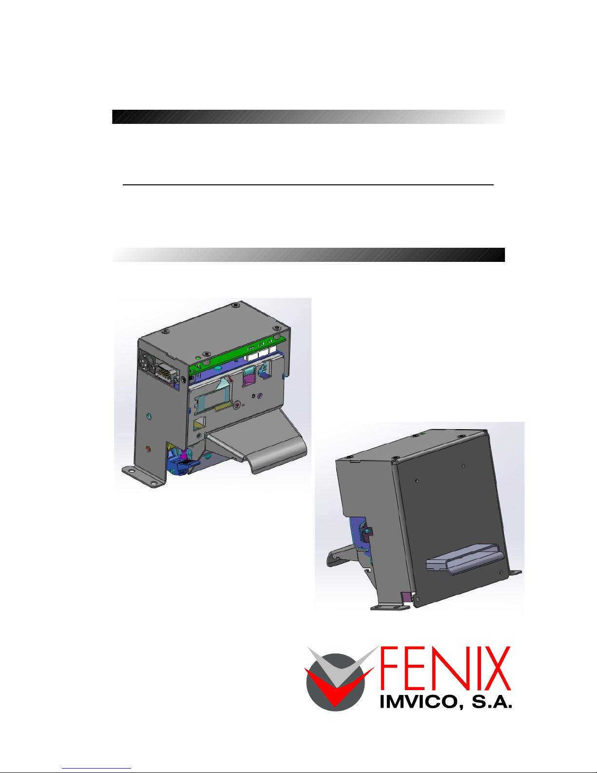
The PTD55 is a very high-performance thermal printer, specially designed as Parking Ticket
Dispenser, for standard parking tickets 54mm wide.
The PTD55 mounts the EPSON M-T522II printer mechanism. Its compact and functional design covers
many industrial uses. It is capable of printing text, graphics, logo and bar codes.
PTD55 is intended to be integrated into the user’s final system. Its structure allows an easy connection
both with the mechanism connectors and with the communications and power supply connectors.
Main features of the PTD55 thermal printer are:
• Simple installation and easy maintenance.
• 54mm Paper width.
• High speed printing: up to 250mm/s
(NOTE 1)
.
• Single 24V DC power supply.
• Available sensors: No-paper, paper-near-end, optical mark, ticket pick-up and paper jam.
• Programmable optional output for user control (buzzer, LEDs, relay..)
• Printing resolution: 8 dots/mm (203 dpi).
• Port interface: - Serial RS232C data input interface on-board (up to 115200bps).
- Universal Serial Bus (USB2.0).
• Scalable font (independent scale in X / Y axis), up to 64 times.
• Programmable character and line space.
• Bold, underline, reverse and rotate character capabilities
• Graphic bitmap printing capabilities.
• Several format bar code (EAN13, Code39, Code128 and ITF).
• Several 2D format Bar Code (QR and AZTEC).
• Two internal character fonts (A font = 12x24 dots. B font = 8x16 dots).
• Control code based on ESC / POS commands
(NOTE 2)
.
• Automatic paper load.
• Four maintenance counters (On/Off times, hours, meters and cuts)
• Hexadecimal mode for easy software debugging.
• Self test mode feature
• Input buffer of 32KBytes.
• Multiple logo load capability through Windows driver or command.
• Upgrading of firmware version through communication port
(NOTE 3)
.
• TrueType font loading capability
(NOTE 3)
.
• Extended operating temperature range (-20ºC to +70ºC).
• Storage temperature range (-35ºC to +75ºC).
• Automatic cut with partial or full cut capability.
• Windows XP and Windows 7 drivers and demo/configuration program.
• Linux Driver.
(1) Print speed changes according to the baud rate in RS232 connection and temperature. Higher printer speed rates are
achieved at higher baud rates and USB connection.
(2) ESC/POS are registered trademarks of Seiko Epson Corporation.
(3) In order to upload new firmware or new TrueType font, FWLoader and FontLoader application programs are available
on our website.
This manual is the printer operations’ guide and is intended for the designer’s application. The
following sections contain a detailed description of both hardware and configuration software that allow
obtaining the maximum benefit of the printer capabilities.
3 of 57
Page 4

PTD55 SERIES OPERATION MANUAL
2 - IMPORTANT NOTES ON THERMAL PRINTER HANDLING
In order to preserve the life of the printer, it is necessary to keep in mind some precautions on the
handling of the PTD55 printer. Please read carefully the following points in order to make a good use of
the printer.
2.1 - SAFETY PRECAUTIONS
• Before using the printer, read carefully section - INSTALLATION.
• NEVER connect the external power supply with the wrong polarity. This could permanently
damage the printer.
• Turn off the printer immediately if it produces smoke, a strange smell or an unusual noise. Keeping
on using the printer could cause fire. Unplug the equipment immediately and contact your official
distributor.
• NEVER connect cables with different connectors from the ones mentioned in this manual. Failing
on doing so could permanently damage the printer.
• Use a power supply whose output voltage is within the specification range stated in this manual.
Over voltage can permanently damage the printer. Under voltage can cause malfunctions.
• NEVER wet PTD55 thermal printer with water or any other liquid. If any liquid is spilled inside the
equipment, unplug the power cable immediately and contact the technical service.
• Make sure the printer is on a steady, securely fixed surface. If the printer falls down, it could break
or damage.
• NEVER use the printer in high humidity or in locations with high risk of fire.
• NEVER place heavy objects on top of the printer and never lean on it.
• NEVER put any object inside of the printer, as it could cause hardware damage on it, such as
short-circuit, print head breaking or general failure of the printer.
• NEVER shake the printer.
• NEVER disassemble or modify the hardware of the printer.
• NEVER try to repair the printer. Please contact your official distributor in case of failure.
• As the printer contains electromagnets (inside of the motor), it should not be used in excessively
dirty environments or places with dust or metal particles.
• NEVER print without paper loaded or without the cover closed, as the thermal print head life can
be highly shortened.
• NEVER pull the paper out when the cover is closed. Use the paper advance button instead.
• Avoid touching accessible parts with metallic objects, such as screwdrivers or tweezers, the print
head thermal elements as well as the electronic printed circuit. They are delicate parts.
• NEVER touch with bare hands the areas around the print head and the motor surface as they
become very hot during and just after printing; wait 15 seconds after printing to let them cool down.
• NEVER touch the surfaces of the print head thermal elements or the electronic printed circuit, as
dust and dirt can stick to their surface and cause damage by electrostatic discharge. Moreover,
some electronic components can get very hot during operation.
• The thermal paper contains Na+, K+ and Cl- ions that can cause harm to the print head elements.
Therefore, use only the specified paper.
• If the printer has not been used for long period of time and the paper was loaded, the paper could
become deformed by the drive roller pressure. It is recommended to make it advance at least 30
mm before printing again.
• For safety reasons, unplug the printer if it is not going to be used over a long period of time.
• Do not print continuously (without stopping) for more than 6 minutes.
4 of 57
Page 5
PTD55 SERIES OPERATION MANUAL
2.2 - ABSOLUTE MAXIMUM RATINGS
Supply voltage . . . . . . . . . . . . . . . . . . . . . . . . . . . . . . . . . . . . . . . . . . . . . . . . . . . . . . . . . . . +30VDC
Operating temperature range . . . . . . . . . . . . . . . . . . . . . . . . . . . . . . . . . . . . . . . . . . . −20°C to 70°C
Storage temperature range . . . . . . . . . . . . . . . . . . . . . . . . . . . . . . . . . . . . . . . . . . . . . −35°C to 75°C
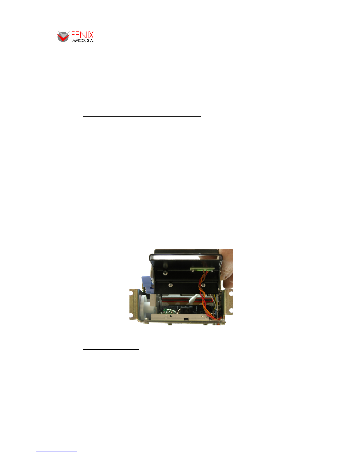
2.3 - CLEANING PROCEDURE AND PRECAUTIONS
Paper dust, paper chips, and thermal chemicals attached to the heat elements of the print head
and the platen may reduce print quality. In order to clean the thermal print head, proceed as indicated by
the following steps:
1- Unplug the power supply cable and open the cutter unit.
2- Pull the paper lever in order to release the platen.
3- Soak a cotton sponge in alcohol (ethanol, methanol or IPA), and rub it gently along the
thermal head in order to remove the possible accumulation of paper particles.
4- Wait for alcohol to evaporate before inserting the paper roll and closing the cover.
FENIX recommends cleaning the thermal print head periodically (every 2 or 3 months) in order
to keep an optimal print quality.
NOTES:
The print head may be hot after printing. Make sure it has thoroughly cooled down
before proceeding to clean it.
Never touch the thermal elements of the print head with your hands.
Never use metallic or piercing elements to clean the print head, as they could scratch it.
Fig.2.1. Thermal print head cleaning.
2.4 - RECOMMENDATIONS
• The plug has to be located near the printer and has to be easily obtainable.
• Before connecting any communication data cable, check the printer is working properly by
executing the self-test.
• Set the PTD55 in a place where the connection cables do not suffer stretching or cross with
each other.
• IMPORTANT!!! Since the printer demands high current peaks during operation it is advisable to
make the power supply cables the shortest possible.
5 of 57
Page 6
PTD55 SERIES OPERATION MANUAL
3 - GENERAL SPECIFICATIONS
3.1 - PRINTING SPECIFICATIONS
Printing method Thermal line printing
Dot density 203 x 203 dpi
(1)
Printing direction Unidirectional with friction feed
Printing width M-T522II 60mm (448 dots)
Printing width available 54 mm (432 dots)
Printing speed High speed mode: up to 250mm/s
(2)
Paper feed speed 250mm/s (continuous paper feed)
(1)
‘dpi’: dots per inch. 1 inch = 25.4mm; 203 dpi = 8 dots per mm
(2)
Printing speed could vary depending on the print head temperature as well as the command processing and
the data transmission speed. Low transmission speed could cause intermittent printing. It is recommended to
transmit data to the printer as quickly as possible.
3.2 - CHARACTER SPECIFICATIONS
Character per line (default) Font A: 24 Font B: 32
Character spacing (default) 0.5 mm (4 dots)
Character structure
Font A: 12 x 24 dots (1.5 x 3 mm). (default)
Font B: 8 x 16 dots (1 x 2 mm).
Character size (mm)
(1)
Font A WxH(mm) – cpl
(2)
Font B WxH(mm) – cpl
Standard
Double-width
Double-height
Double width/height:
1.5 x 3 – 24
3 x 3 – 12
1.5 x 6 – 24
3 x 6 – 12
1 x 2 – 32
2 x 2 – 16
1 x 4 – 32
2 x 4 – 16
Number of characters
Alphanumeric characters: 95
Extended Graphics: 128 per page
Line spacing (default) 1,875mm (15 dots)
(1)
Characters can be scaled up to 64 times bigger than their normal size.
(2)
‘cpl’: characters per line.
3.3 - PAPER SPECIFICATIONS
Paper type Thermal
Paper specifications
T2CH826
T28I381
T21I06S (all from Ifb Ticket Systems)
T28H960
T29J10S
Paper loading Automatic.
Width 54mm
NOTES:
→ Print quality varies depending on paper types.
→ Use the specified thermal paper, or proper print quality may not be obtained, the life of the
print head and autocutter unit may be shortened, or printer troubles may be caused.
6 of 57
Page 7
PTD55 SERIES OPERATION MANUAL
3.4 - COMMUNICATIONS INTERFACE
Serial Serial interface RS232 (baud options: 115200, 38400, 19200, 9600)
USB USB 2.0 480Mbit/s
3.5 - DIGITAL OUTPUT
Max Drive current 100mA continuous, 200mA peak.
Max supported voltage 45VDC open-drain
3.6 - INTERNAL BUFFER
The standard PTD55 printer has a 32 Kbytes internal memory buffer, whose functionality is
dynamically shared by the receiving buffer.
The buffer is being filled at the same time that buffered data is being printed, for that reason high
transmission speed is required in order to ensure that data is available for printing at any time. Data
transfer of at least 115200 bauds or USB connection increase the printing performance substantially.
3.7 - ELECTRICAL SPECIFICATIONS
Power supply: +24VDC ± 10%
Consumption:
80mm paper-width model 60mm paper-width model
High speed mode Mean current Approx. 9A Approx. 6.5A
Peak current Approx. 14A Approx. 10A
Standby mode Mean current Approx. 0.1A Approx. 0.1A
3.8 - BARCODE SPECIFICATIONS
Standard barcodes EAN-13, CODE39, ITF, CODE128
2D barcodes AZTEC, QR
3.9 - MECHANICAL SPECIFICATIONS
Overall dimensions (W x D x H) See APPENDIX – MECHANICAL DIMENSIONS
Weight 900g approx.
7 of 57
Page 8
PTD55 SERIES OPERATION MANUAL
3.10 - RELIABILITY AND ENVIROMENTAL CONDITIONS
Printer service life 15 millions lines
MCBF 37 millions lines
Print head service life
(1)
100 Km, one hundred million pulses
Autocutter service life
(1)
1 million cuts
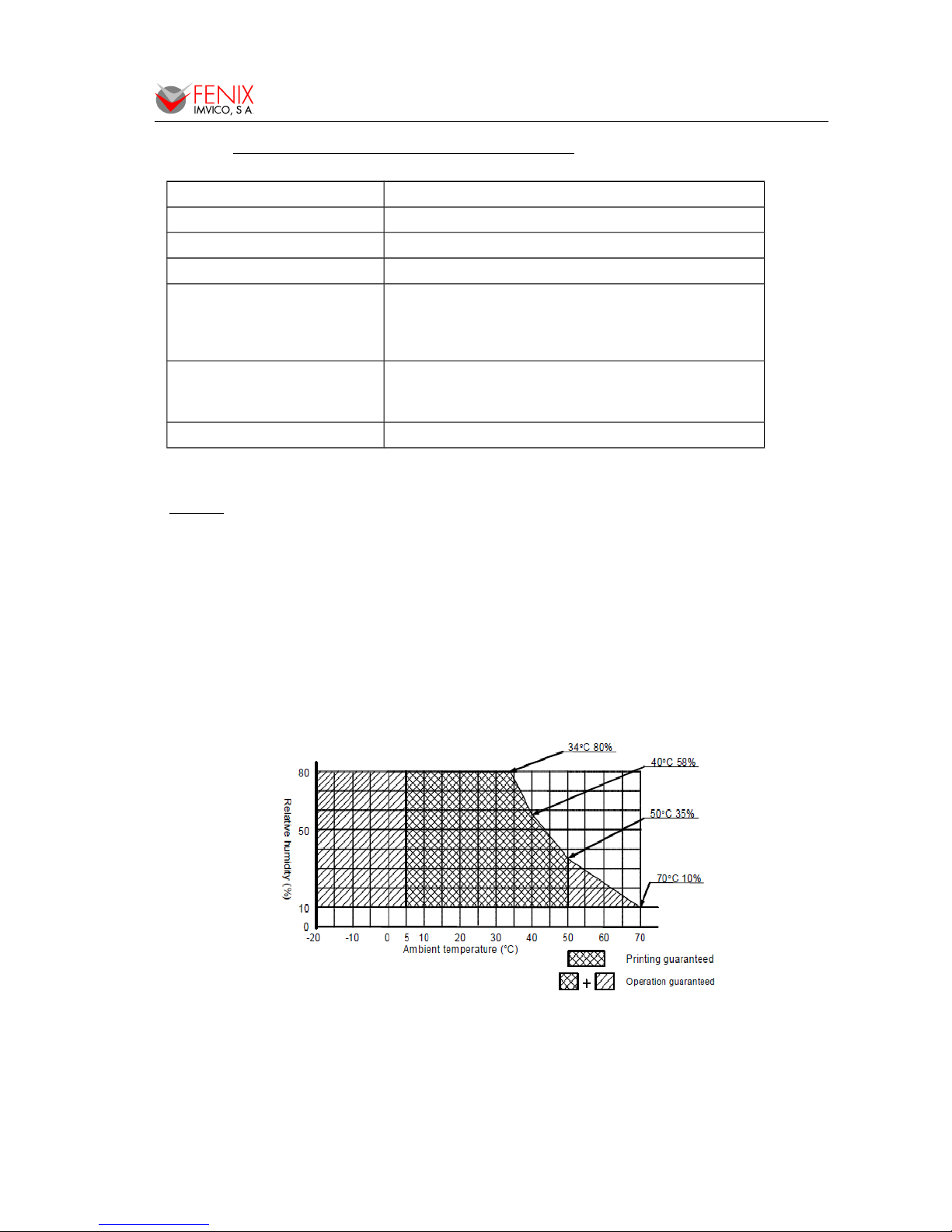
Operating temperature
-20 to 70ºC
Reliable printing: 5 to 50°C
Note that there are some restrictions, depending on the
temperature range
Operating humidity
10 to 80% (non-condensing)
(Humidity at 34°C or higher is equivalent to the absolute
humidity at 34°C, 80%.)
Storage temperature -35 to 75ºC (without paper, in a dry place)
(1) The service life of the print head and autocutter may become shorter if paper other than specified is used.
NOTES:
1. Reliability statistics assume that the printer repeats printing in which one dot line
consists of an average of 112 dots or less, and the average number of printing dots
per dot line per element is 30.
2. Life end is defined as the point at which two or more adjacent heat elements are
damaged (when two or more adjacent dots are omitted), except when damaged by
foreign objects or external causes.
3. The print head life is measured using the specified paper.
4. Using the printer with the density correction factor of the print head energization
width set to a value larger than 1 may shorten the life of the print head
5. The ambient temperature should be kept close to room temperature.
Stop printing when the print head temperature detected by the head thermistor reaches 75°C.
Resume printing when the temperature drops down to 70°C for lower.
Fig.3.1. Operating temperature and humidity range.
8 of 57
Page 9
PTD55 SERIES OPERATION MANUAL
4 - INSTALLATION
4.1 - INSTALLATION CONSIDERATIONS
The PTD55 is designed to be fixed in a bigger case or structure or another kind of appropriate
chassis. A wrong installation may cause many issues like paper jam, difficult maintenance of the printer,
difficulty in changing the paper, etc. Moreover, a correct installation can prevent the printer from being
damaged by external agents, such as weather or vandalism.
The basic points that a correct installation must follow are:
• Smooth exit of the ticket. Prevent problems with static electricity due to the nature of the
used materials. Be sure to make a good earth connection.
• Prevent final user’s from accessing the printer outlet.
• Allow enough room and accessibility to reach the maintenance procedure points in case it is
needed. Take notice all user accessible parts in the printer:
– Printing Head
– Paper box location.
– Connectors.
– Led and push-button.
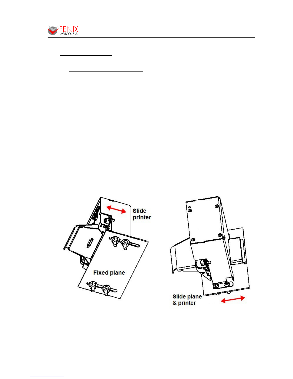
• Fix the PTD55 printer to the chassis by using four screws (Ø5mm maximum) as shown on
the pictures below. It is recommended to implement some system to allow the printer to be
moved backwards when accessing the printing head. Below it is shown how to fix the printer
onto a detachable or sliding tray or practice fixing slots on the supporting base, so that the
PTD55 can be moved backwards and forwards for easy maintenance.
Fig.4.1. Fixing the PTD55 onto a sliding tray or through fixing slots.
9 of 57
Page 10
PTD55 SERIES OPERATION MANUAL
• Below it is shown a slot example to be performed on the front side of the kiosk to put the paper
nozzle across.
Fig.4.2. Slot example for paper nozzle (in mm).
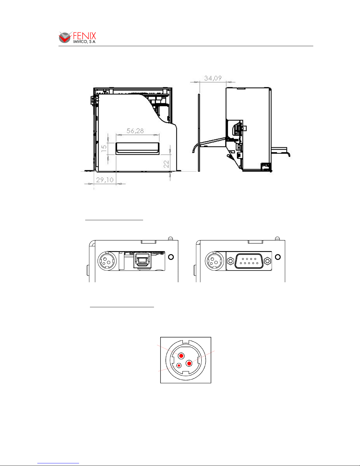
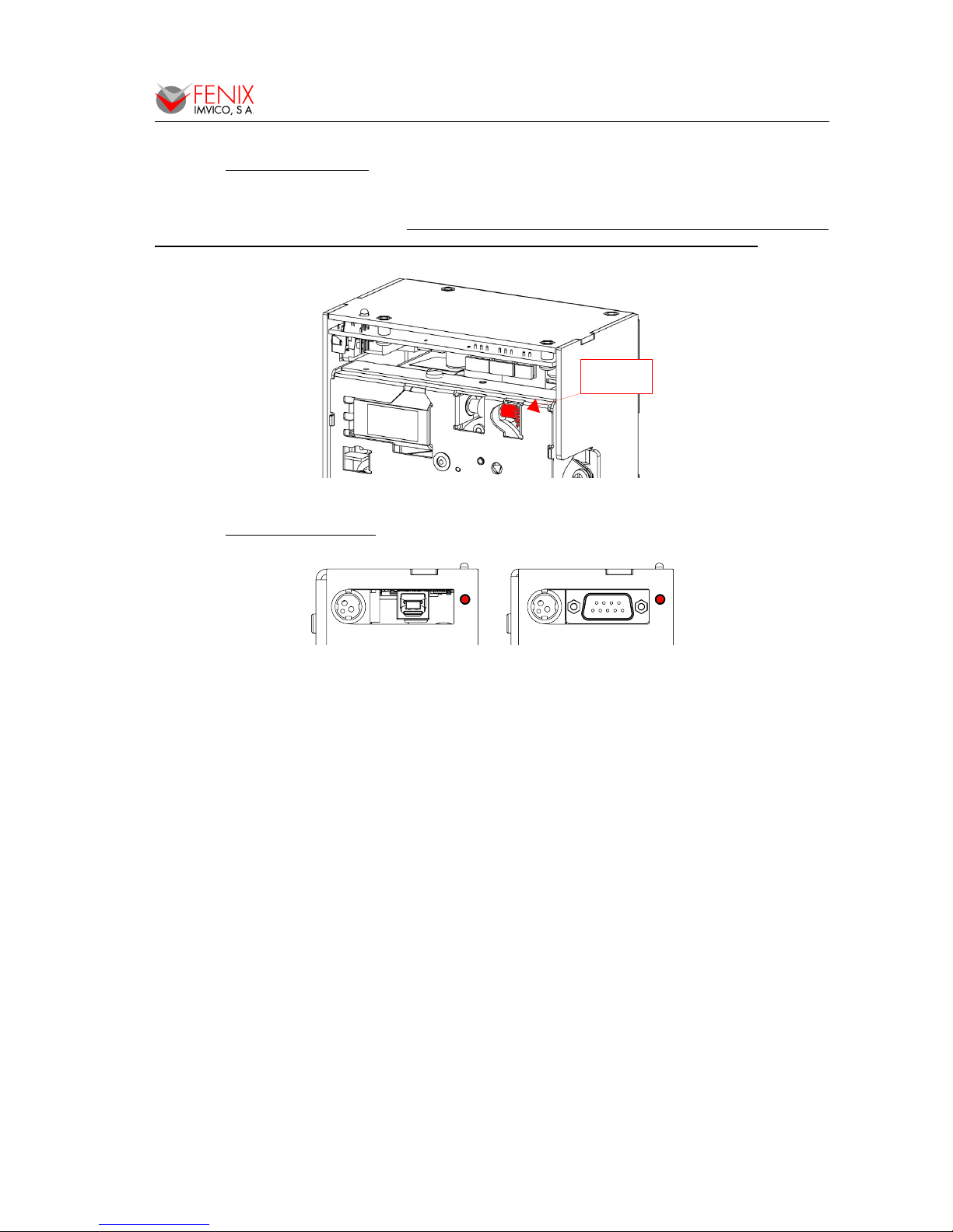
4.2 - PTD55 CONNECTORS
On the PTD55 could be found the following connectors (see APPENDIX HOW TO ORDER):
Fig.4.3. USB or SERIAL RS232 interface connectors.
4.2.1 - Power supply connector
The PTD55 is powered by an external power supply by means of 3-pins connector shown below.
Verify power supply voltage before connecting the printer.
Fig.4.4. Power supply connector J1.
Use a 3-pin DC jack TCS-7960-43-2010 (HOSIDEN) or equivalent. (See APPENDIX – HOW TO
ORDER-ACCESSORIES).
10 of 57
POWER
SUPPLY
POWER
SUPPLY
USB RS232
GND
24VDC
N.C
Page 11

PTD55 SERIES OPERATION MANUAL
NOTES:
(1) The PTD55 requires one power source: VCC (24VDC) for driving the thermal head and
motor.
(2) If the number of dots that are energized at the same time is increased, a higher current
will flow; therefore, a power supply with an adequate current capability must be used.
(3) When designing printing lines and bit images, take the printing ratio and print duty into
consideration. Print quality may be poor if the printing ratio (energizing pulses/dot line) or
print duty is high.
(4) Average energizing pulse width is defined as 64 of 192 dots/dot line that are energized.
WARNING: Beware not to invert the polarity of power supply. This may
irremediably damage the printer. Ensure that the voltage is the correct
one.
IMPORTANT NOTE ABOUT POWER SUPPLY:
The required power supply depends on the content printed on the ticket. A 150W power
supply covers all adverse possibilities (printing ratio of 100% black at any temperature).
However, if the print ratio is not over 60%, a 60W power supply can be used. In any case, power
supply must satisfy the peaks current that mechanism requires, which are determined by the
following formula:
Ipeak = [24/657] x number of printing dots
FENIX offers different power supplies as an accessory option (See APPENDIX – HOW TO
ORDER). These power supplies which have been exhaustively tested are available in open frame or
enclosed version.
4.3 - RS-232 SERIAL INTERFACE
4.3.1 - RS-232 Serial interface specifications
• Data transmission type: Serial
• Synchronization: Asynchronous
• Flow control: None, Hardware and Xon/Xoff
• Signal levels (RS232): MARK = -3 to -15 V Logic ‘1’/OFF
SPACE = +3 to +15 V Logic ‘0’/ON
• Speed: 9600, 19200, 38400 and 115200 bauds.
• Data length: 8 bits
• Parity: none, even and odd
• Stop bits: Fixed to 1
• Connector (user side): Male D-SUB9 pin connector
4.3.2 - Change between online and offline mode
The printer is in offline mode:
1) When powering up or resetting the printer, until the printer is ready to receive data.
2) When the door is opened.
3) After pressing the button while the paper advances.
4) When ‘out of paper’ causes the printer to stop printing.
5) When the power supply has a temporal abnormal voltage change.
6) When an error has occurred.
11 of 57
Page 12
PTD55 SERIES OPERATION MANUAL
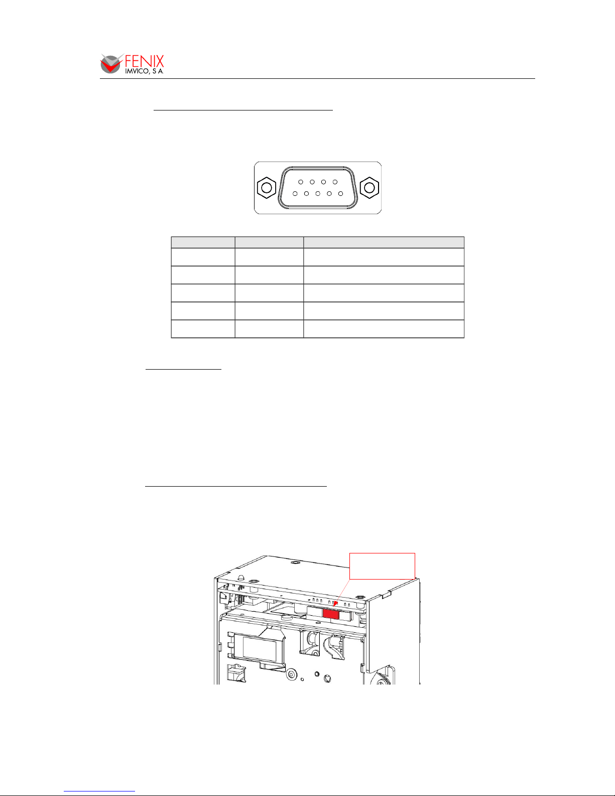
4.3.3 - Serial RS-232 interface pins assignment
The assignments of the terminals of the RS-232 connector and the functions of its signals are
described in the following figure and table:
Fig.4.5. Serial RS-232 interface pins.
Pin number Signal name Function
5 SGND Signal ground
2 RXD Data reception line
3 TXD Data transmission line
7 RTS Indicates whether the printer is busy
other - Not connected
4.4 - USB INTERFACE
The PTD55 USB interface has the following general features:
• USB specification USB 2.0 (480Mbits/s full speed)
• Transfer type Bulk
• Maximum receive/transmit endpoint size 64 bytes
• Current consumption from USB bus 2mA max.
User has to use a standard “B” series USB connector.
4.5 - PAPER NEAR-END INPUT CONNECTION
The PTD55 has an optional input which can be used to warn the maintenance operator that the
printer is running out of paper although there is still paper to print few tickets. When the remaining paper
in the box reaches a level that can be considered "near-end", the system can alert the operator to
replace by another box of paper. This can be done by querying the status of the printer (DLE EOT n =4
command).
Fig.4.6. Paper near-end input connector.
12 of 57
1
6
5
9
PAPER
NEAR-END
CONNECTOR
Page 13
PTD55 SERIES OPERATION MANUAL
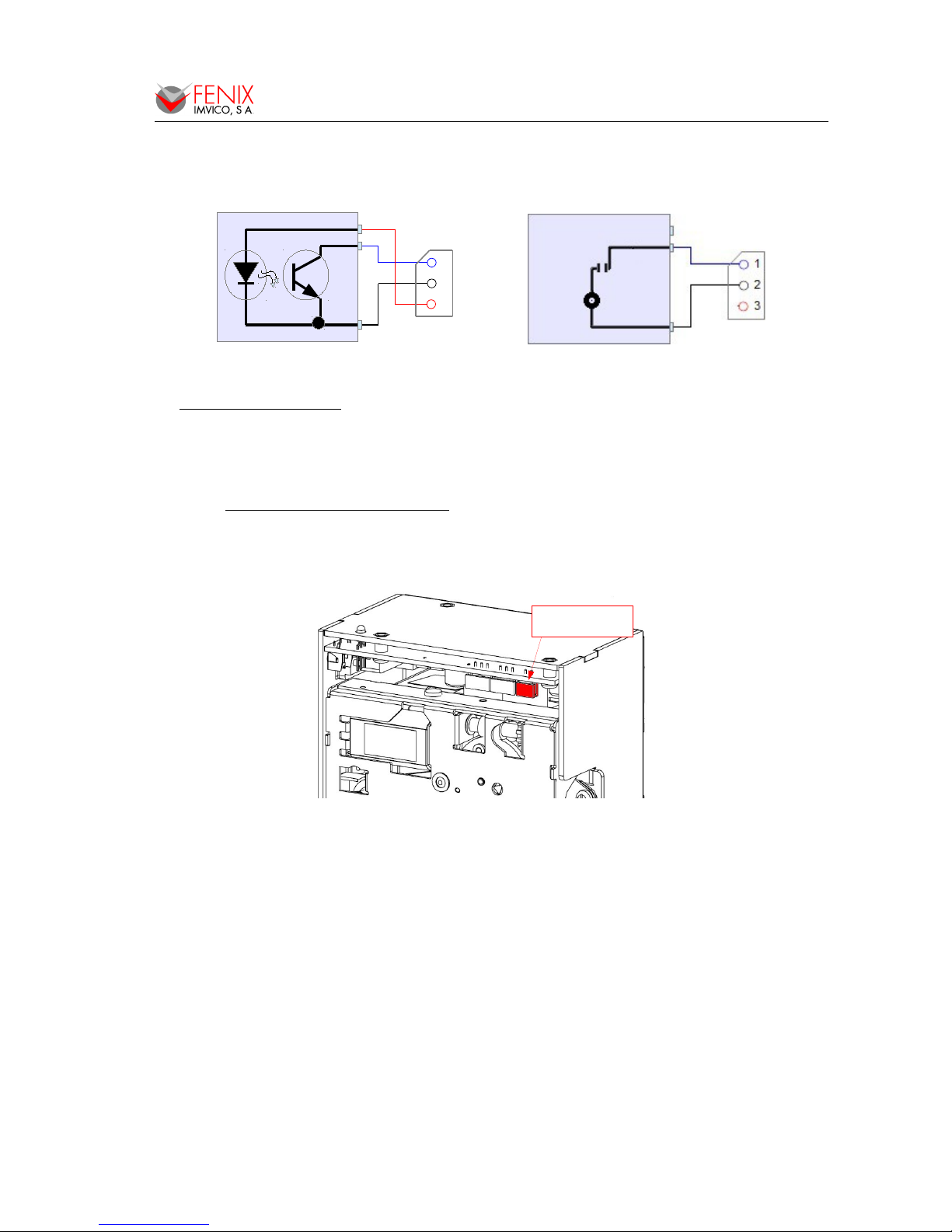
The developer can connect both sensor type photo-reflective or simple contact.
See available accesories in APPENDIX HOW TO ORDER.
Fig.4.7. Connection of both sensor types: photo-sensor or simple contact.
User side connector type
Housing: QH250-03H (Plastron)
Contact: QH250T-010 (Plastron)
4.6 - DIGITAL OUTPUT CONNECTION
The PTD55 has an optional output which can be used for different purposes such a blink and
external warning light when a ticket has not been picked up or the printer is running out of paper,
activate a beeper when previous or other events are triggered, etc.
Fig.4.8. Digital output connector.
Housing: QH250-02H (Plastron)
Contact: QH250T-010 (Plastron)
The open collector transistor output can be triggered either by any of the error events or can be
activated instantaneously using the same command: DC3 p m ton toff .
13 of 57
DIGITAL OUTPUT
CONNECTOR
1
2
3
Page 14
PTD55 SERIES OPERATION MANUAL
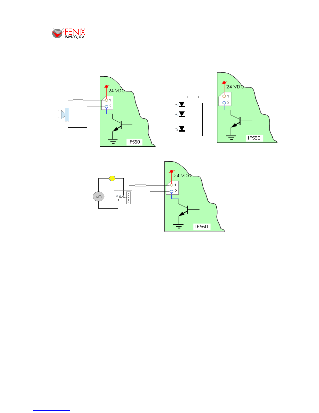
The digital output provides a signal that can blink or stay stable for up to 16 cycles. In case that a
blinking output is preferred, the time the output stays on and off are also programmable.
Driving a buzzer. Driving a led array.
Driving a relay.
Fig.4.9. Digital output examples.
The transistor's output capability is: Vco = 45V , IC = 100mA. Values beyond this absolute
maximum ratings could result in a permanent damage of the device.
14 of 57
R
R
R
220V
AC
Page 15
PTD55 SERIES OPERATION MANUAL
5 - BASIC OPERATIONS
The PTD55 contains an internal photo-sensor that acts as optical mark detector. In most cases, the
optical mark is a hole (corner cut), whereby the sensor is mechanically located at one end side of the
ticket 54mm. The PTD55 uses the space between two consecutive corners (“black mark”) to identify the
cut positioning.
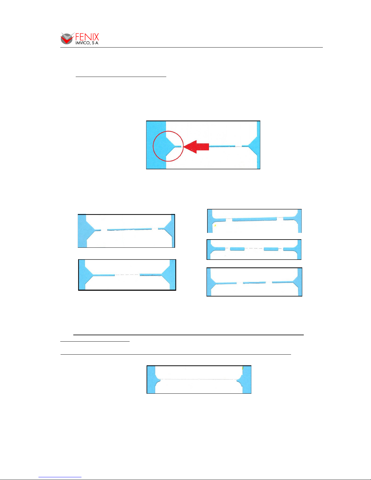
Fig.5.1. Corner to positioning the cutting.
Because there really is not a standard set (only the width and length: 54x85mm), there may be
numerous types of corners and joints between tickets:
Fig.5.2. Real examples of preformed tickets.
NOTE: FENIX recommended to use tickets with straight cut corners (45º), as large as
possible, as in Figure 5.1.
Some types of preformed tickets, like the following image, may not function properly.
Fig.5.3. Preformed ticket NOT recommended.
15 of 57
Page 16
PTD55 SERIES OPERATION MANUAL
5.1 - ADJUST ING THE CUTTING POSITION BY COMMAND
3.1- To adjust the distance between the black mark and cutting line, the PTD55 provides the
standard command GS ( G nL nH mL mH, where:
hexadecimal
GS ( G : 1D 28 47 → Command head (Always fixed).
nL nH : A8 02 → Total length of the ticket in dots (Always fixed).
85 mm = (85 x 8) dots = 680 dots
680 decimal = 02A8 hexadecimal
mL mH : 1C 00 → Offset distance in dots between the top of the black mark and the next
cutting line of the ticket in the feed direction (Variable depending on
the preformed).
As it indicated above, the fact that there are different preformed, as well as mechanical tolerances
and mounting, causes the mLmH distance is variable.
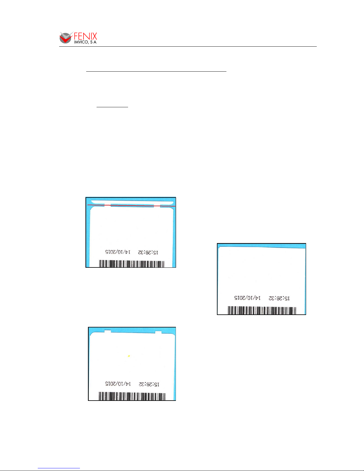
An example of trial-error adjustment is shown:
1.- For the preformed shown in the image,
suppose that you start by mLmH = 1C00 value and
the cut has exceeded the desired line (in red).
2.- In a second attempt, decreasing the
value of mLmH = 0200, pruduce the opposite
result. The cut occurs before the desired line.
3.- Therefore, by selecting an intermediate value
mLmH = 0800, the cut is achieved in the right
place.
16 of 57
Page 17

PTD55 SERIES OPERATION MANUAL
5.2 - CUTTING POSITION SELF-ADJUSTING
The PTD55 has a self-adjusting, whereby the parameter mLmH is estimated practically.
To perform the self-adjusting follow these steps:
1º ) Turn the printer off and the head lever down.
2º ) Keeping the PFEED button pressed, turn the printer on and lift the head lever.
Immediately the PTD55 will issue 4 tickets and will make a cut. From here, each time the PFEED button
is pressed a ticket is issued and cut with the parameters calculated.
If the final result of self-adjusting is not satisfactory, the developer must fit the parameter mLmH by
sending the command GS ( G nL nH mL mH (see above).
NOT E S :
- After sending the GS ( G command (or by self-adjusting), the parameters are stored in non-
volatile memory.
- When pressing the paper feed button the printer will feed paper to the next cutting line according
to the parameters set with the GS ( G command.
- When sending any cut command to the printer will do the same as above.
- When sending a GS FF command to the printer it will feed paper to the next cutting line.
- If the printer detects that paper has been fed for a distance larger that the ticket length without
having cut the paper, it will pop a black mark error.
- The first ticket should be discarded since the printer cannot estimate the distance to the next
cutting line until it has detect at least one black mark.
5.3 - LOADING PAPER
5.3.1 - Automatic paper loading
1. Make sure the PTD55 is power supplied.
2. Remove any rest of paper if there is any.
3. Make sure that the platen is closed.
4. Make sure the paper end is cut in a straight way.
5. Thread the paper roll with the right orientation as shown in the next figure. The thermal
paper has only one printing side (thermal side). If there are doubt about which one is the
printing side, just scratch the paper and the thermal side will show up the track on.
6. Once the printer has detected the paper, it will automatically start the paper load sequence
which consist of feeding few millimeters of paper at a very low speed.
Note: running at low speed, the motor will be noisier.
5.3.2 - Manual paper loading
1. Open the printing head by pulling the lever and remove the paper (if there is any). Keep
the printing head open.
2. Place the paper roll in the right direction.
3. Put the paper end in the mechanism inlet. Push the paper in until it reaches the
mechanism outlet.
4. Close the printer head.
17 of 57
Page 18
PTD55 SERIES OPERATION MANUAL
5.4 - OPEN CUTTER UNIT
Sometimes the cutter could get jammed if thicker paper is used, the printer mechanism is not
properly closed or other reason. In that case the printer will report a cutter error and may not be possible
to open the printer mechanism to fix it. In order to, manually release the cutter blade the cutter unit
has a wheel that, when turned, will move the cutter blade up or downwards depending.
Fig.5.4. Unlocking the cutter blade.
5.5 - BUTTON FUNCTIONS
Fig.5.5. Button location in USB and SERIAL interfaces.
The on-board button has the following functions:
• PAPER FEEDING: when the printer is powered on pressing the button will feed the paper.
The paper roller will not move under the following conditions:
- The paper roll end sensor detects a paper end.
- When the door is open.
- When another non-recoverable error is present.
• SELF-TEST MODE: If pressed on start-up with the door closed, it activates this mode.
• HEXADECIMAL MODE: In order to activate it, if the button is still pressed when the full Self-
test has been printed, the printer will prompt the user to hold the button to enter this mode. If
we do not hold the button in the next 3 seconds (meaning NO), the printer will exit to normal
operation.
18 of 57
CUTTER
WHEEL
Page 19

PTD55 SERIES OPERATION MANUAL
5.6 - SPECIAL PRINTING MODES
Besides the normal printing mode in which all the received data are printed according to the
settings or conditions fixed by the commands, the PTD55 printer allows two special working modes:
self-test mode and the hexadecimal mode.
5.6.1 - Self-test mode
The printer provides the selftest mode with two different
functionality: showing information
of the settings of that particular
printer model and verifying the
printing.
To enter the self-test mode,
the printer must be powered on
while keeping pressing the button.
The PTD55 will start printing a
report, which allows checking the
features of this particular model,
like the firmware current version,
control functions of the
communications protocol, and so
on.
Once this printing has been
finished, if the button is kept
pressed; the printer will start
printing continuously and
repetitively a character pattern until
it finally concludes the self-test by
printing ‘* * completed * *’. This
second option of the self-test mode
has the goal of validating the
printing speed and quality.
At the end of the self-test
page there are few lines showing
the four different maintenance
counts:
1- Times that the printer has been
switched on.
2- Time (in half hours) that the
printer has been powered on.
3- Meters of paper printed.
19 of 57
Fig.5.6. SELF-TEST
mode example.
!”#$%&'()*+,-./01234567
!”#$%&'()*+,-./012345678
”#$%&'()*+,-./0123456789
#$%&'()*+,-./012345679 :
$%&'()*+,- ./012345679 : ;
%&'()*+,-./0123456779 : ; <
&'()*+,-./0123456779 : ; < '()*+,-./0123456779 : ; < - >
()*+,-./0123456779 : ; < - >?
)*+,-./0123456779 :;< - >?@
*+,-./0123456779 :;< - >?@A
+,-./0123456779 :;< - >?@AB
,-./0123456779 :;< - >?@ABC
.
.
.
.
.
vwxyz{ | }~ !”#$%&'()*+,
wxyz{ | }~ !”#$%&'()*+,xyz{ | }~ !”#$%&'()*+,-.
yz{ | }~ !”#$%&'()*+,-./
z{ | }~ !”#$%&'()*+,-./0
{ | }~ !”#$&'()*+ , - . /01
| }~ !”#$&'()*+ , - . /012
* * completed * *
FENIX IMVICO
IF550 V1.7.1
MECHANISM: M-T52XII-60mm
SERIAL PORT SETTINGS
Data bits: 8 (fixed)
Stop bits: 1 (fixed)
Baud rate: 115200 bauds
Parity bit: No parity
Protocol: Hard.RTS/CTS
USB PORT SETTINGS
USB V2.0 480Mbits/s
DEFAULT TEXT SETTINGS
Set character EUROPE 437
Table A (12x24 dots)
Character Height: 1
Character Width: 1
Character space: 4
Line space: 15
Print density: Standard
Black mark: Disabled
Near-end-paper Disabled
Carry Return: Disabled
CUTTER SETTINGS
Automatic full & partial
EXTERNAL TABLES:
(No table loaded)
LOGOS LOADED:
(No logo loaded)
* RECORDS *
Serial num. 0FE057057142
On/Off times: 100
Meters: 100
Cuts: 100
Time ON(H:M): 0:10
Page 20

PTD55 SERIES OPERATION MANUAL
• FACTORY CONFIGURATION
Some parameters are preset at the factory. However, the developer can change these settings by
FenixDemo program (www.feniximvico.com) or by commands.
Black Mark: Enable → It is essential to enable the black mark sensor and allow proper
operation of the PTD55.
Printing speed : 100 mm/s → It allows a sharper impression, especially in the barcodes and
Print density: DARK protected thermal paper.
Baud rate: 9600 bauds
5.6.2 - Hexadecimal dump mode
To enter the hexadecimal mode, proceed in the same way as in the continuous self-test, but keeping
pressing the button until printing "Enter in hexadecimal mode?...".
Then continue with the button pressing for four seconds until
the text "~~~ HEXADECIMA MODE ~~~" has been printed.
This mode can be very helpful for the application developer
during the setup test time, as it allows detecting possible errors
(like out of range parameters, non valid command sequences,
errors in the communication channel, etc.), comparing what it has
theoretically been sent to the printer to what it is really being received.
Turn off the printer to quit the hexadecimal mode.
NOTES:
(1) For any received characters under 20h, the ASCII
‘.’ will not be printed.
(2) During the hexadecimal dump mode, the DEL EOT
command does not work.
(3) It must be taken into account that if the number of
bytes is less than the minimum amount required to
print one line (9 bytes), the printer will not print. It is
recommended to complete the hexadecimal dump
by sending at least 9 bytes (for example 00h).
(4) It is also possible to enter the hexadecimal mode
through the GS (A command.
Fig.5.7. HEXADECIMAL DUMP mode example.
20 of 57
1B21001B330A1B2004
. ! . .3. . . .
1B61011B45001D4200
a. . E. .B. .
1B2D001B56300A1D21
-. .V0. . !U
55544553540A1D2100
UTEST. . !.
1B61301B33011B2001
. a0.3. . . .
1B4D001B74001D4C00
M. .t. . L. .
001B45001D42001B2D
. E. .B . .-.
001B56300A54657874
.V0 .Text .
0A2D2D2D2D0A46454E
- - - - . FE
4958207072696E7465
NIX print
722073616D706C6520
er sample
7469636B65740A0A0A
ticket . . .
0A0A0A1B6D
. . . . m
Enter hexadecimal mode?...
Page 21

PTD55 SERIES OPERATION MANUAL
5.7 - ERROR PROCESSING
When an error occurs, the printer visually notifies its type through the LED. This fact allows the
final user to have a direct and visual reference of the current printer status.
On the other hand, the printer status and all its possible errors can also be monitored via software
through the “DEL EOT n” command or activating the automatic status reporting “GS a n” command. In
this way, the application developer can have more complete information on the printer status, therefore
being able to act accordingly.
FENIX recommends that developers include in their applications a flow chart like the one shown
below, to have monitored the printer.
Fig.5.8. Flowchart for error detection.
21 of 57
Page 22

PTD55 SERIES OPERATION MANUAL
NOTES
(*1) All DLE EOT n commands sent should have associated a time_out to detect a
communication failure or malfunction in the printer. This time_out can be 1s <= T10> = 0.5s.
(*2) The goal of this second time_out is to control that ticket has been printed:
transmission, processing, printing and cutting have been implemented and process to that ticket
is completed. The value of this time_out depends on the ticket.
5.6.1- Error types
When any of these errors happen, the led blinks
with a different blinking timing sequence and
color for each of them according to the figure
below. If no error happens the led will light
permanently green.
Fig.5.9. Error status indicator LED.
Fig.5.10. LED Blinking sequence. Each time unit corresponds to 0.5 seconds.
More information on these errors can be found below:
NEAR END PAPER WARNING
[Description] At run time, the printer checks periodically, through the near-end paper sensor,
if there is enough remaining paper in the paper roll. If the printer in running out
of paper the printer will warn visually the user. The print will not stop working.
This error is informational only (warning).
[Status flags] This error involves the following flags activation:
n=<04>H Continuous paper sensor status → Paper not present bit 3=”1”.
[Recover action] Change the paper roll by a new one.
22 of 57
1 5 10 15 20 25 30
No error
Nea r-end p a per
Tic ket not pic ked up
Hardw are error
Input v oltag e error
Te mpe ra ture e rror
C utter e rror
Blac k mark error
Pa per jam error
No pa per / door open
Page 23

PTD55 SERIES OPERATION MANUAL
TICKET NOT PICKED UP WARNING
[Description] Every time a ticket is printed if the correspondent sensor is properly installed
in the output paper nozzle, the printer will warn that the ticket has not been
picked up. The print will not stop working. This error is informational only
(warning).
[Status flags] This error involves the following flags activation:
n=<05>H Paper sensor status → Ticket not pick-up bit 3=”0”.
[Recover action] Remove the printed ticket from the output paper nozzle.
HARDWARE ERROR
[Description] At initialization, the printer internally checks its hardware devices (i.e. flash
memory). If they do not function properly, an error occurs.
[Status flags] This error involves the following flags activation:
n=<01>H Printer status → Offline bit 3=”1”.
n=<02>H Offline status → Error occurred bit 6=”1”.
[Recover action] This error cannot be recovered. One of the control board components might
be damaged and should be replaced or repaired.
VP VOLTAGE ERROR
[Description] The voltage of the VP voltage converter is out of range.
[Status flags] This error involves the following flags activation:
n=<01>H Printer status → Offline bit 3=”1”.
n=<02>H Offline status → Error occurred bit 6=”1”.
n=<03>H Error status → Unrecoverable error occurred bit 5=”1”.
[Recover action] This is an unrecoverable error. Unplug the power supply from the printer and
check if the output voltage of the power supply is within the specified range.
Replace it in case it is not working properly.
[Note] When this error occurs, some parts of the printer may be damaged. If this
happens, the printer will be unable to recover itself and some of its
components are likely to be replaced.
THERMAL HEAD TEMPERATURE ERROR
[Description] Due to very continuous use of the printer or due to environmental conditions,
the temperature in the thermal head may reach levels (above 80ºC), which
can damage the printer itself. When this situation occurs, an error must be
indicated in order to protect the printer from abrasion.
[Status flags] This error involves the following flags activation:
n=<01>H Printer status → Offline bit 3=”1”.
n=<02>H Offline status → Error occurred bit 6=”1”.
n=<03>H Error status → Auto-recoverable error occurred bit 6=”1”.
[Recover action] The printing recovers automatically from this error when the thermal print head
temperature drops below 60ºC again.
[Note] This error can happen if the ambient temperature is very high and the printer
is working continuously with high-density printing.
23 of 57
Page 24

PTD55 SERIES OPERATION MANUAL
CUTTER ERROR
[Description] If the cutter is not working correctly either due to an internal malfunction or a
paper jam, this error pattern will be triggered.
[Status flags] This error involves the following flags activation:
n=<01>H Printer status → Offline bit 3=”1”.
n=<02>H Offline status → Error occurred bit 6=”1”.
n=<03>H Error status → Unrecoverable error occurred bit 5=”1”.
→ Cutter error occurred bit3=”1”.
[Recover action] The printer tries to automatically recover from this error at printer initialization
(turning the printer on). Remove paper jam and try recovering the cutter blade
turning the printer on some times. If the autocutter does not return to its
normal position by itself, manually rotate the cutter motor gear to return the
cutter to its original position. (See Section - OPEN CUTTER UNIT.)
BLACK MARK ERROR
[Description] It will be triggered when, being the black mark option set, the printer has cut a
ticket but has not found the next black mark. The possible reasons may be:
a) The paper does not have black mark.
b) The black mark is not in the right position.
c) The black mark does not have the right size or intensity
[Status flags] This error involves the following flags activation:
n=<01>H Printer status → Offline bit 3=”1”.
n=<02>H Offline status → Error occurred bit 6=”1”.
n=<03>H Error status → Unrecoverable error occurred bit 5=”1”.
[Recover action] If paper with no black marks is used replace it by the correct one.
[Note] Two consecutive black marks cannot be separated more than 50cm.
PAPER JAM ERROR
[Description] If an object obstructs the output, the paper may jam in the platen roller.
[Status flags] This error involves the following flags activation:
n=<01>H Printer status → Offline bit 3=”1”.
n=<02>H Offline status → Error occurred bit 6=”1”.
n=<03>H Error status → Unrecoverable error occurred bit 5=”1”.
n=<04>H Continuous paper status → Paper present bit 2=”1”.
[Recover action] Open the platen unit and remove the jammed paper.
Also, depending on the paper type, paper dust may stick to the platen and
may cause malfunction of the paper jam detector. In this case, clean the
platen roller.
24 of 57
Page 25

PTD55 SERIES OPERATION MANUAL
NO PAPER ERROR / PLATEN OPEN
[Description] The out-of-paper sensor detects there is not paper on the printing line. When
the door is open the printer will also detect it the same way.
[Status flags] This error involves the following flags activation:
n=<01>H Printer status → Offline bit 3=”1”.
n=<02>H Offline status → Error occurred bit 6=”1”.
→ Printing is being stopped bit5=”1”.
→ Platen is open bit2=”1”.
n=<04>H Continuous paper status → Paper not present bit 6=”1”.
[Recover action] This error disappears loading a new paper roll in the printer and closing the
paper door (see section - PAPER LOADING).
[Note] This error stops the printing and it cannot be restarted until it is not recovered.
This error is indicated in the parallel port depending on the conditions set by
the ESC c 3 command (see section - CONTROL COMMANDS).
25 of 57
Page 26

PTD55 SERIES OPERATION MANUAL
6 - CONTROL COMMANDS
Command Name Command Name
LF Print and line feed FS p Print NV bit image
CR Print and carriage return FS q Define NV bit image
DC3 p Enable digital output FS DC2 ESC Serial number query
DLE EOT Real-time status transmission FS GS ESC Historic counters transmission
DC3 ESC
FS GS
Program printer settings
ESC SP Set right-side character spacing
ESC DC2
GS BEL
Save current settings
ESC DC3
GS BS
Save default settings
ESC ! Select print mode(s)
ESC – Turn underline mode on/off
ESC 2 Select default line spacing
ESC 3 Set line spacing
ESC @ Initialize printer
ESC E Turn emphasized mode on/off
ESC G Turn double-strike mode on/off
ESC I Turn reverse mode on/off
ESC J Print and feed paper
ESC M Select character font
ESC V Character rotation
ESC a Select justification
ESC c 4 Select paper-near-end sensor to stop printing
ESC d Print and feed n lines
ESC i Full cut
ESC j Back feed paper
ESC m Partial cut
ESC t Select character code table
ESC&yc1 c2 Load an external character table
ESC { Inverse print mode on/off
GS FF Feed marked paper to print starting position
GS ! Select character size
GS ( A Execute test print
GS ( C Erase all logos
GS ( G Set ticket length & cut offset related to black
mark
GS B Turn white/black reverse printing mode on/off
GS E Set printing speed
GS H Select printing position of HRI characters
GS I n Firmware version query
GS L Set left margin
GS P Print a 2D AZTEC format barcode
GS Q Print a 2D QR format barcode
GS q n Set 2D barcode size
GS T Set print position to the beginning of print line
GS V Select cut distance and cut paper
GS a n Automatic status report
GS f Select font for HRI characters
GS h Set bar code height
GS k Print bar code
GS v 0 Print raster bit image
GS w Set bar code width
26 of 57
Page 27

PTD55 SERIES OPERATION MANUAL
LF
[Name] Print and line feed
[Format] ASCII LF
Hex 0A
Decimal10
[Description] Prints the data in the print buffer and feeds one line, based on the current line spacing.
[Note] This command sets the print position to the beginning of the line.
[Reference] ESC 2, ESC 3.
CR
[Name] Print and carriage return
[Format] ASCII CR
Hex 0D
Decimal13
[Description] When automatic line feed is enabled, this command operates the same as LF; when
automatic line feed is disabled, this command is ignored.
[Notes] ● This command is effective only it is programmed with such functionality (see
command DC3 ESC FS GS)
● Sets the print starting position to the beginning of the line.
[Reference] LF
DC3 p m ton toff
[Name] Enable digital output
[Format] ASCII DC3 p m ton toff
Hex 13 70 m ton toff
Decimal19 112 m ton toff
[Range] <00>H ≤ m, ton, toff
≤
<FF>H
[Description] Enables the digital output which can be triggered either by an error event or intentionally
The parameter m is composed by to nibbles. The high nibble sets the triggering event
while the lower one set the number of complete cycles to be output.
m (hex)
high nibble
m (hex)
low nibble
Function
0 0 to F No event. Output directly by command
1 0 to F Output triggered by hardware error
2 0 to F Output triggered by Vp voltage error
3 0 to F Output triggered by temperature error
4 0 to F Output triggered by cutter error
5 0 to F Output triggered by no-paper error
6 0 to F Output triggered by platen-opened error
7 0 to F Output triggered by black mark error
8 0 to F Output triggered by ticket not picked up error
9 0 to F Output triggered by paper-near-end error
A 0 to F Output triggered by paper jam error
Setting No-event associated to the digital output causes that the output will be enabled
immediately by the command while associating it to an event, such as near-end-paper
error, for instance, will cause that each time near-end-paper is detected, the digital
output will be enabled. ton and toff are the time the digital output is in on or off estate
respectively.
27 of 57
Page 28

PTD55 SERIES OPERATION MANUAL
The time unit is 0.01seg. The examples below shows how it look like different output
signals with the parameters on the right-side.
1s m = 0x03
2s ton = 100
toff = 200
1s 1s 1s m = 0x03
ton = 100
toff = 0
0.5s m = 0x07
ton = 50
toff = 50
[Notes] In order to disable an output associated to an event, the same command must be sent
specifying the event in the m parameter but setting ton and toff to 0.
DLE EOT n
[Name] Real-time status transmission
[Format] ASCII DLE EOT n
Hex 10 04 n
Decimal16 4 n
[Range] <01>H ≤ n
≤
<04>H
[Description] Transmits the selected printer status specified by n in real-time, according to the
following parameters:
n = <01>H: Transmit printer status
n = <02>H: Transmit offline status
n = <03>H: Transmit error status
n = <04>H: Continuous paper sensor status
n = <05>H: Paper sensor status
[Notes] ● The status is transmitted whenever the data sequence <10>H<04>H<n>
(<01>H ≤ n
≤
<05>H) is received.
● The printer transmits the current status. Each status item is represented by one byte.
● The printer transmits the status without confirming whether the host computer can
receive data (in serial interface).
● The printer executes this command upon receiving it.
● This command is executed even when the printer is offline, the receiver buffer is full,
or there is an error status with a serial interface model.
n = <01>H: Printer status
Bit OFF/ON Function
0 OFF Not used. Fixed to OFF
1 ON Not used. Fixed to ON
2 OFF Not used. Fixed to OFF
3
OFF Online
ON Offline
4 ON Not used. Fixed to ON
5
OFF Does not wait for online error recovery
ON Waits for online error recovery
6* ON/OFF Ticket completed
7 OFF Not used. Fixed to OFF
(*) Bit 6 is toggled every time a cut command is executed
28 of 57
Page 29

PTD55 SERIES OPERATION MANUAL
n = <02>H: Offline status
Bit OFF/ON Function
0 OFF Not used. Fixed to OFF
1 ON Not used. Fixed to ON
2
OFF Platen is closed (Thermal head is closed)
ON Platen is open (Thermal head is open)
3 - Undefined
4 ON Not used. Fixed to ON
5
OFF No paper-end stop
ON Printing is being stopped
6
OFF No error
ON Error occurred
7 OFF Not used. Fixed to OFF
n = <03>H: Error status
Bit OFF/ON Function
0 OFF Not used. Fixed to OFF
1 ON Not used. Fixed to ON
2 OFF Not used. Fixed to OFF
3
OFF No cutter error
ON Cutter error occurred
4 ON Not used. Fixed to ON
5
OFF No unrecoverable error
ON Unrecoverable error occurred
6*
OFF No auto-recoverable error
ON Auto-recoverable error occurred
7 OFF Not used. Fixed to OFF
(*) Bit 6 is ON when printing is stopped due to high print head temperature
until the print head temperature drops sufficiently.
n = <04>H: Continuous paper sensor status
Bit OFF/ON Function
0 OFF Not used. Fixed to OFF
1 ON Not used. Fixed to ON
2
OFF Paper jam sensor: Paper not present
ON Paper jam sensor: Paper present
3 OFF Paper near-end sensor: Paper present
29 of 57
Page 30

PTD55 SERIES OPERATION MANUAL
ON Paper near-end sensor: Paper not present
4 ON Not used. Fixed to ON
5 - Undefined
6
OFF Paper real-end sensor: Paper present
ON Paper real-end sensor: Paper not present
7 OFF Not used. Fixed to OFF
n = <05>H: Paper sensor status
Bit OFF/ON Function
0 OFF Not used. Fixed to OFF
1 ON Not used. Fixed to ON
2 - Undefined
3
OFF Ticket not pick up
ON Ticket pick up
4 ON Not used. Fixed to ON
5 - Undefined
6 - Undefined
7 OFF Not used. Fixed to OFF
DC3 ESC FS GS
[Name] Program printer settings
[Format] ASCII DC3 ESC FS GS n s1...sn
Hex 13 1B 1C 1D n s1...sn
Decimal19 27 28 29 n s1...sn
[Range] <00>H ≤ n ≤ <07>H
[Description] Changes any of the programmable settings and saves them into non-volatile memory.
Any of the settings can be programmed simultaneously with any other settings.
n is the number of printer settings to be changed, and s1...sn indicates the type and
new value of the setting as follows:
[Notes] ● Once the command has been sent the printer will save the new setting into non-
volatile memory and print a message indicating if the feature has been saved
successfully, or on the contrary if the feature is not supported. It is required,
therefore, to have the paper roll installed.
● After this command has been executed, the printer will reset itself automatically in
order to activate new settings.
● If communications setting are changed it will be required to change them also in the
host controller in order to reestablish communications.
● The number and order of setting changed it is not important.
Feature s (high nibble) s (low nibble) value
1- Paper width 0
1 60mm
2 80mm
3 82.5mm
30 of 57
Page 31

PTD55 SERIES OPERATION MANUAL
2- Baudrate 1
0 9600 bauds
1 19200 bauds
2 38400 bauds
3 115200 bauds
4 230400 bauds
3- Parity 2
0 Odd parity
1 Even parity
2 No parity
4- Handshaking 3
0 Hardware
1 Xon/Xoff
2 No handshake
5- Cutter 4
0 No cutter
1 Total cut
2 Partial cut
3 Total/partial cut
6- Printing density 5
0 Normal
1 Light
2 Dark
7- Black Mark 6
0 Enable
1 Disable
8- Carriage return 7
0 Enable
1 Disable
9- Near-end paper sensor 8
0 Enable
1 Disable
[Example] The following command will change baudrate to “115200 bauds”, parity to “Even” and
handshake to “No handshake”.
13 1B 1C 1D 03 13 21 32
handshake
parity
baudrate
number of setting
If all the features are supported by the printer, it will print the following message on
paper:
Feature saved successfully-> 2
Feature saved successfully-> 3
Feature saved successfully-> 4
The settings can also be changed through our DEMO Fenix application that can be downloaded
from our website feniximvico.com.
31 of 57
Page 32

PTD55 SERIES OPERATION MANUAL
ESC SP n
[Name] Set right-side character spacing
[Format] ASCII ESC SP n
Hex 1B 20 n
Decimal27 32 n
[Range] <00>H ≤ n ≤ <FF>H
[Description] Sets the character spacing for the right side of the character to [n x 0.125 mm (n x
0.0049”)].
[Notes] ● The right side character spacing for double-width mode is twice the normal value.
● This command is effective only when sent at the beginning of a line.
[Default] n = <04>H
ESC DC2 GS BEL
[Name] Save current settings into non-volatile memory
[Format] ASCII ESC DC2 GS BEL
Hex 1B 12 1D 07
Decimal27 18 29 07
[Description] Saves current configuration into flash memory so when the printer is restarted, current
configuration will be loaded.
[Notes] The parameters that will be saved are line spacing, character spacing, character table,
character width and height.
ESC DC3 GS BS
[Name] Save default settings into non-volatile memory
[Format] ASCII ESC DC3 GS BS
Hex 1B 13 1D 08
Decimal27 19 29 08
[Description] Saves default configuration (factory settings) into flash memory so when the printer is
restarted, default configuration will be loaded.
[Notes] The parameters that will be saved are line spacing, character spacing, character table,
character width and height.
ESC ! n
[Name] Select print mode(s)
[Format] ASCII ESC ! n
Hex 1B 21 n
Decimal27 33 n
[Range] <00>H ≤ n ≤ <FF>H
[Description] Selects print mode(s) using n as follows:
Bit OFF/ON Hex Function
0
OFF 00 Character font A (12 x 24).
ON 01 Character font B (8 x 16).
1 -- -- Undefined.
2 -- -- Undefined.
3
OFF 00 Emphasized mode not selected.
ON 08 Emphasized mode selected.
4
OFF 00 Double-height mode not selected.
ON 10 Double-height mode selected.
5
OFF 00 Double-width mode not selected.
ON 20 Double-width mode selected.
6 -- -- Undefined.
7
OFF 00 Underline mode not selected.
ON 80 Underline mode selected.
32 of 57
Page 33

PTD55 SERIES OPERATION MANUAL
[Notes] ● When both double-height and double-width modes are selected, quadruple-size
characters are printed.
● When some characters in a line are double or more height, all the characters in the
line are aligned at the baseline.
● ESC E can also select the emphasized mode. Be careful when uses both command.
● ESC M can also select character font type. However, the setting of the last received
command is effective.
● GS ! can also select character size. However, the setting of the last received
command is effective.
● If this command is not received at the beginning of a line, and the character font is to
be changed, all previous data in the print buffer is printed and the ticket is placed at
the beginning of the next line.
[Default] n = <00>H
[Reference] ESC M, ESC E, ESC G, GS !
ESC - n
[Name] Turns on/off underline mode
[Format] ASCII ESC - n
Hex 1B 2D n
Decimal 27 45 n
[Range] <00>H ≤ n ≤ <FF>H
[Description] Sets the underline mode. Only the least significant two bits are valid for n:
n = <00>H / <30>H : Underline mode is turned off.
n = <01>H / <31>H: Set the underline thickness to 1-dot.
n = <02>H / <32>H: Set the underline thickness to 2-dots.
[Notes] ESC ! command can turns off the underline mode.
[Default] n = <00>H
[Reference] ESC !
ESC 2
[Name] Select default line spacing
[Format] ASCII ESC 2
Hex 1B 32
Decimal27 50
[Description] Selects 3.75 mm (30 x 0.125 mm) line spacing.
[Reference] ESC 3
ESC 3 n
[Name] Set line spacing
[Format] ASCII ESC 3 n
Hex 1B 33 n
Decimal27 51 n
[Range] <00>H ≤ n ≤ <FF>H
[Description] Sets the line spacing to [n x 0.125 mm].
[Default] n = <1E>H
[Reference] ESC 2
ESC @
[Name] Initialize printer
[Format] ASCII ESC @
Hex 1B 40
Decimal27 64
[Description] Clears the data in the print buffer and resets the printer settings to the settings that were
in effect when the power was turned on.
[Notes] ● The data in the receiver buffer is not cleared.
● This command does not involve a hardware reset.
33 of 57
Page 34

PTD55 SERIES OPERATION MANUAL
ESC E n
[Name] Turn emphasized mode on/off
[Format] ASCII ESC E n
Hex 1B 45 n
Decimal27 69 n
[Range] <00>H ≤ n ≤ <FF>H
[Description] Turns emphasized mode on or off
When the LSB of n is 0, emphasized mode is turned off.
When the LSB of n is 1, emphasized mode is turned on.
[Notes] ● Only the least significant bit of n is enabled.
● This command and ESC ! turns on and off emphasized mode in the same way.
Be careful when this command is used with ESC !.
[Default] n = <00>H
[Reference] ESC !, ESC G
ESC G n
[Name] Turn on/off double-strike mode
[Format] ASCII ESC G n
Hex 1B 47 n
Decimal27 71 n
[Range] <00>H ≤ n ≤ <FF>H
[Description] Turns double-strike mode on or off.
When the LSB of n is 0, double-strike (emphasized) mode is turned off.
When the LSB of n is 1, double-strike (emphasized) mode is turned on.
[Notes] Printer output is the same in double-strike mode and in emphasized mode.
[Default] n = <00>H
[Reference] ESC E
ESC I n
[Name] Turn reversed mode on/off
[Format] ASCII ESC I n
Hex 1B 49 n
Decimal27 73 n
[Range] <00>H ≤ n ≤ <FF>H
[Description] Turns reversed mode on or off
When the LSB of n is 0, reversed mode is turned off.
When the LSB of n is 1, reversed mode is turned on.
[Default] n = <00>H
[Notes] Only the least significant bit of n is enabled.
ESC J n
[Name] Print and feed paper
[Format] ASCII ESC J n
Hex 1B 4A n
Decimal27 74 n
[Range] <00>H ≤ n ≤ <FF>H
[Description] Prints the data in the print buffer and feeds the paper [n x 0.0625 mm (0.0024”)].
[Notes] ● After printing is completed, this command sets the print starting position to the
beginning of the line.
● The paper feed amount set by this command does not affect the values set by ESC 2
or ESC 3.
34 of 57
Page 35

PTD55 SERIES OPERATION MANUAL
ESC M n
[Name] Select character font
[Format] ASCII ESC M n
Hex 1B 4D n
Decimal27 77 n
[Range] n = <00>H, <01>H, <30>H, <31>H
[Description] Selects the character font.
n Function
<00>H <30>H Character Font A (12 x 24) selected
<01>H <31>H Character Font B (8 x 16) selected
[Notes] ● ESC ! can also select character font types. However the setting of the last received
command is effective.
● This command must be sent at the beginning of a line. If it is sent in the middle of a
line, all previous data in the print buffer is printed and the ticket is placed at the
beginning of the next line.
[Reference] ESC !
ESC V n
[Name] Character rotation
[Format] ASCII ESC V n
Hex 1B 56 n
Decimal27 86 n
[Range] <00>H ≤ n ≤ <02>H, <30>H ≤ n ≤ <32>H
[Description] Rotates the characters using the mode specified by n.
n Function
<00>H / <30>H Normal
<01>H / <31>H Right 90º rotated
<02>H / <32>H Left 90º rotated
In both left and right 90º rotated modes, the characters lines transmission
order changes from the normal mode, because can be printing several lines at
once.
Example for right 90º rotation mode:
Characters lines transmission order
1st line: T A T H <CR>
2nd line: E <SP> H E <CR>
. . . . . .
. . . . . .
Last line: <SP> T S <SP> <CR>
[Notes] ● The vertical and horizontal character scaling effect to paper feed direction regardless
of the character rotation setting.
● It is not allowed both normal and rotated mode in the same character line.
● When any rotated mode is setting, the inverse mode is disabled.
● This command is enabled only when processed at the beginning of a line.
[Default] n = <30>H
[Reference] GS !
35 of 57
H E L L O
T H I S I S
A P R I N T
T E S T
Paper feed direction
Page 36

PTD55 SERIES OPERATION MANUAL
ESC a n
[Name] Select justification
[Format] ASCII ESC a n
Hex 1B 61 n
Decimal27 97 n
[Range] <00>H ≤ n ≤ <02>H, <30>H ≤ n ≤ <32>H
[Description] Aligns all the data in one line to the specified position.
n selects the justification as follows:
n Justification
<00>H / <30>H Left justification
<01>H / <31>H Centering
<02>H / <32>H Right justification
[Notes] ● The command is enabled only when processed at the beginning of the line.
● This command executes justification in the printing area.
[Reference] ESC !
[Example]
Left justification Centering Right justification
ESC c 4 n
[Name] Select paper-near-end sensor to stop printing
[Format] ASCII ESC c 4 n
Hex 1B 63 34 n
Decimal 27 99 52 n
[Range] <00>H ≤ n ≤ <FF>H
[Description] Selects whether the paper-near-end sensor stops printing.
When the bit 1 of n is 0, paper near-end sensor does not stop printing.
When the bit 1 of n is 1, paper near-end sensor will stop printing.
[Notes] When bit 1 is on, in paper-near-end is detected, the printer goes offline and stop
printing.
ESC d n
[Name] Print and feed n lines
[Format] ASCII ESC d n
Hex 1B 64 n
Decimal27 100 n
[Range] <00>H ≤ n ≤ <FF>H
[Description] Prints the data in the print buffer and feeds n character lines.
[Notes] ● This command sets the print starting position to the beginning of the line.
● This command does not affect the line spacing set by ESC 2 or ESC 3.
● The maximum paper feed amount is 1016 mm {40”}. If the paper feed amount (n x
line spacing) of more than 1016 mm {40”} is specified, the printer feeds the paper
only 1016 mm {40”}.
● Every line feed corresponds to the current selected font height (24 dots for Font A
and 16 dots for Font B).
[Reference] ESC 2, ESC 3.
36 of 57
ABC
ABCD
ABCDE
ABC
ABCD
ABCDE
ABC
ABCD
ABCDE
Page 37

PTD55 SERIES OPERATION MANUAL
ESC i
[Name] Full Cut
[Format] ASCII ESC i
Hex 1B 69
Decimal27 105
[Description] Cuts the paper completely in the current position.
[Notes] ● If this command is sent without cutter connection the printer enters cutter error status.
● The interval between each cutting operation must be two seconds or more.
● When the black mark sensor is set to be effective, the printer feeds paper to (black
mark ± [(value which is set by GS ( F) x 0.125mm]) and cuts it. After cutting, it feeds
paper to the position specified by the command GS ( F. (See section – BLACK MARK
SENSOR)
[Reference] GS ( F, ESC m, GS V
ESC j n
[Name] Back feed paper
[Format] ASCII ESC j n
Hex 1B 6A n
Decimal27 106 n
[Range] <00>H ≤ n ≤ <FF>H
[Description] Back feeds the paper [n x 0.0625 mm (0.0024”)].
[Notes] ● This command is only effective when the optical mark sensor is enabled.
● Allows readjust the paper position when the black mark has surpassed the black
mark sensor, and it is needed back feed paper to prepare the cutting.
ESC m
[Name] Partial Cut
[Format] ASCII ESC m
Hex 1B 6d
Decimal27 109
[Description] Cuts the paper partially in the current position.
[Notes] ● If this command is sent without cutter connection, the printer enters cutter error
status.
● The interval between each cutting operation must be two seconds or more.
● This command performs the partial cut even when the black mark is enabled, but no
action relative to black mark is performed.
[Reference] ESC i, GS V.
ESC t n
[Name] Selects the character tables
[Format] ASCII ESC t n
Hex 1B 74 n
Decimal27 116 n
[Range] <00>H ≤ n ≤ <03>H, <30>H ≤ n ≤ <33>H
[Description] Selects the character tables between the internal ones or the external ones loaded.
n Character table selected
<00>H / <30>H Both internal tables A and B are selected.
<01>H / <31>H
External loaded table A is selected.
Internal table B is selected.
<02>H / <32>H
External loaded table B is selected.
Internal table A is selected.
<03>H / <33>H Both external loaded tables A and B are selected.
[Default] n = <30>H
[Reference] APPENDIX – INTERNAL CHARACTER TABLES.
37 of 57
Page 38

PTD55 SERIES OPERATION MANUAL
ESC & y c1 c2 [table name] [ table data]
[Name] Load an external character table
[Format] ASCII ESC & y c1 c2 [table name] [table data]
Hex 1B 26 79 c1 c2 [table name] [table data]
Decimal27 38 12 c1 c2 [table name] [table data]
[Range] y = <00>H to table A (12x24 format); y = <01>H to table B (8x16 format).
c1= <20>H; c2 = <FF>H
[table name] : 24 Byes (ASCII characters).
Padded with <20>H (“SPACE” character) to get the 24 bytes, if needed.
[table data] : 10752 bytes to table A or 3584 bytes to table B.
20H to FFH → 224 characters
12 bits → 2 bytes; 224 x (2x24) = 10752 bytes.
8 bits → 1 byte ; 224 x (1x16) = 3584 bytes.
[Description] Load an external character table in non-volatile memory.
[Notes] ● The memory space available for external tables only allows to load one table A
plus one B.
● Loading a new table (A or B) means losing the previous loaded.
● Through the self-test it can check the tables currently loaded in the printer.
[Reference] APPENDIX – INTERNAL CHARACTER TABLES.
ESC { n
[Name] Inverse printing mode
[Format] ASCII ESC { n
Hex 1B 7B n
Decimal27 123 n
[Range] <00>H ≤ n ≤ <FF>H
[Description] Turns inverse printing mode on/off.
When the LSB of n is 0, Inverse printing mode off.
When the LSB of n is 1, Inverse printing mode on.
[Notes] ● Each character is printed upside down (180º rotating) and the sequence of
characters is printed backwards as well. The character sent fist is printed al the right
margin and subsequent characters are printed from right to left. The characters lines
transmission order changes from the normal mode, because the first line is sent to
the printer must be the last to appear on the ticket, and the last line is sent must be
the first to appear on the ticket.
● When inverse mode is setting, the rotated mode (90º) is disabled.
● This command is enabled only when processed at the beginning of a line.
[Default] n = <00>H
38 of 57
A B C D
1 2 3 4 5
A B C D
1 2 3 4 5
Paper
feed
direction
Inverse printing
mode OFF
Inverse printing
mode ON
Page 39

PTD55 SERIES OPERATION MANUAL
GS FF
[Name] Feed marked paper to print starting position
[Format] ASCII GS FF
Hex 1D 0C
Decimal29 12
[Description] Feeds paper until finding the black mark. Then moves the ticket, forward or backward,
placing it at the printing position.
[Notes] ● This command is only effective when the optical mark sensor is enabled.
● This command sets the next print position to the beginning of the line.
● The maximum amount of paper feed until find the black mark is 0,5m.
[Reference] GS ( G
GS ! n
[Name] Select character size
[Format] ASCII GS ! n
Hex 1D 21 n
Decimal29 33 n
[Range] <00>H ≤ n ≤ <77>H. While n ≤ <7X>H and n ≤ <X7>H
[Description] Selects the character height using bits 0 to 3 and selects the character width using bits
4 to 7, as follows:
n
(in hex)
Horizontal size (WIDTH)
x 1 x 2 x 3 x 4 x 5 x 6 x 7 x 8
Vertical size (HEIGHT)
x 1 00 10 20 30 40 50 60 70
x 2 01 11 21 31 41 51 61 71
x 3 02 12 22 32 42 52 62 72
x 4 03 13 23 33 43 53 63 73
x 5 04 14 24 34 44 54 64 74
x 6 05 15 25 35 45 55 65 75
x 7 06 16 26 36 46 56 66 76
x 8 07 17 27 37 47 57 67 77
[Notes] ● This command is effective for all characters, except for HRI characters.
● When characters are enlarged with different sizes on one line, all the characters on
the line are aligned at the baseline.
● The ESC ! command can also turn double-width and double-height modes on or off.
However, the setting of the last received command is effective.
[Default] n = <00>H
[Reference] ESC !
39 of 57
Page 40

PTD55 SERIES OPERATION MANUAL
GS ( A pL pH n m
[Name] Execute test print
[Format] ASCII GS ( A pL pH n m
Hex 1D 28 41 pL pH n m
Decimal 29 40 65 pL pH n m
[Range] (pL + (pH x 256)) = 2 (where pL = <02>H, pH = <00>H)
<00>H ≤ n ≤ <02>H, <30>H ≤ n ≤ <32>H
<01>H ≤ n ≤ <03>H, <31>H ≤ m ≤ <33>H
[Description] ● Executes a test print with a specified test pattern on a specified paper.
● pL, ph specifies (pL+(phx256)) for the number of the bytes after ph (n and m).
● n specifies the paper to be tested.
n Paper
<00> / <30>H
<01> / <31>H
<02> / <32>H
Paper roll
• m specifies a test pattern.
m Test pattern
<01> / <31>H Hexadecimal dump
<02> / <32>H Printer status print
<03> / <33>H Rolling pattern print
[Notes] ● This command has enabled only when processed at the beginning of a line.
● After the test print is finished, the printer resets itself automatically. Therefore, data
already defined before this command is executed, such as user-defined buffer and
print buffer are cleared; and each setting returns to the default value.
● The printer cuts the paper at the end of the test print.
G S ( C pL pH NULL 6 NULL C L R
[Name] Erase all logos
[Format] ASCII GS ( C pL pH NULL 6 NULL C L R
Hex 1D 28 43 pL pH 00 36 00 43 4C 52
Decimal 29 40 67 pL pH 00 54 00 67 76 82
[Range] pL = <06>H (fixed), pH = <00>H (fixed)
[Description] Erases all logos stored in non-volatile memory.
[Reference] FS p, FS q commands.
GS ( G n L n H m L m H
[Name] Set ticket length and cut offset related to black mark
[Format] ASCII GS ( G nL nH mL mH
Hex 1D 28 47 nL nH mL mH
[Range] 0 ≤ (nL + nH x 256) ≤ 65535
0 ≤ (mL + mH x 256) ≤ 65535
(where <00>H ≤ nL, nH, mL and mH ≤ <FF>H)
[Description] (nL + nH x 256) specifies the total ticket length in dots (0.125 mm) and (mL + mH x
256) sets the offset distance, also in dots, between the top of the black mark and the
next cutting line of the ticket in the paper feed direction (see section BLACK MARK
SENSOR).
[Notes] ● Normally, the first ticket printed after powering up the printer must be discarded as it
will have different length that the following ones.
● This command takes into account the distance from the black mark sensor and the
cutter blade which is fixed in a particular assembly. For this reason, this distance
must be kept if a different implementation is taken.
● This parameters are saved in non-volatile memory.
[Default] (nL + nH x 256) = 800 (100mm) ; (mL + mH x 256) = 400 (50mm)
[Reference] GS FF, GS V, ESC i, ESC m
40 of 57
Page 41

PTD55 SERIES OPERATION MANUAL
GS B n
[Name] Turn white/black reverse printing mode
[Format] ASCII GS B n
Hex 1D 42 n
Decimal 29 66 n
[Range] <00>H ≤ n ≤ <FF>H
[Description] Turns on or off white/black reverse printing mode.
When the LSB of n is 0, white/black reverse mode is turned off.
When the LSB of n is 1, white/black reverse mode is turned on.
[Notes] ● Only the lowest bit of n is valid.
● When white/black reverse printing mode is on, it also applied to character spacing set
by ESC SP.
● This command does not affect bit image, user-defined bit image, bar code and HRI
characters.
● This command does not affect the space between lines.
● White/black reverse mode has a higher priority than underline mode. Even if
underline mode is on, it is disabled (but not cancelled) when white/black reverse
mode is selected.
[Default] n = 0
GS E n
[Name] Set printing speed.
[Format] ASCII GS E n
Hex 1D 45 n
[Range] n = <00>H, <10>H, <20>H, <30>H
[Description] Selects the printing speed.
n Printing speed
<00>H Maximum speed
<10>H Fast Speed
<20>H Slow Speed
<30>H Minimum Speed
[Notes] This command can be used when the power supply does not give the current request
(less speed less average current), or when an accurate outline quality is desirable
(less speed best outline quality).
[Default] n = <00>H
GS H n
[Name] Select print position for HRI characters.
[Format] ASCII GS H n
Hex 1D 48 n
Decimal 29 72 n
[Range] <00>H ≤ n ≤ <03>H , <30>H ≤ n ≤ <33>H
[Description] Selects the print position of HRI characters when printing a bar code.
n selects the print position as follows:
n Printing position
<00>H / <30>H Not printed
<01>H / <31>H Above the bar code
<02>H / <32>H Below the bar code
<03>H / <33>H Both above and below the code bar
[Notes] ● HRI indicates Human Readable Interpretation
● HRI characters are printed using X-scale = 1, Y-scale = 1 and the font specified by
GS f.
[Default] n = <02>H
[Reference] GS f, GS k
41 of 57
Page 42

PTD55 SERIES OPERATION MANUAL
GS I n
[Name] Firmware version transmission
[Format] ASCII GS I n
Hex 1D 49 n
Decimal29 73 n
[Range] n = <33>H
[Description] ● Transmits the firmware version number.
● Besides of checking the firmware version by printing the self-test page, this command
can be used as support for possible automatic firmware upgrade through the host
application. Thus, the system could check whether the current version is less than
the new provided (contact with FENIX IMVICO or distributor if necessary).
● Returns one byte indicating numerically the current firmware version and revision (1
st
and 2nd index. 3Rd index indicates the boot firmware version and it is not transmitted
by this command
Example:
GS L nL nH
[Name] Set left margin
[Format] ASCII GS L nL nH
Hex 1D 4C nL nH
Decimal29 76 nL nH
[Range] <00>H ≤ nL ≤ <FF>H, <00>H ≤ nH ≤ <FF>H
[Description] ● Sets the left margin using nL and nH.
● The left margin is set to [(nL + nH x 256) x 0.125 mm].
[Notes] ● This command is effective only when processed at the beginning of the line.
● This commands affects text, graphic and bar code printing.
[Default] nL = nH = <00>H
GS P nL nH d1...dn
[Name] Print a 2D AZTEC format barcode
[Format] ASCII GS P nL nH d1..dn
Hex 1D 50 nL nH d1..dn
Decimal29 80 nL nH d1..dn
[Description] Prints a 2D Aztec barcode with n characters where n = nL + nH x 256.
[Range] nH = <00>H, <00>H ≤ nL ≤ <FF>H.
42 of 57
FENIX IMVICO
TS1700 V1.0.1
SERIAL PORT SETTINGS
Data bits: 8 (fixed)
Stop bits: 1 (fixed)
Baud rate: 115200 bauds
Byte transmitted: 10
Left margin
Printable area
Page 43

PTD55 SERIES OPERATION MANUAL
The maximum number of characters is undetermined as it depends on the available
paper size and the type of characters to be printed (numbers, uppercase / lowercase
characters, etc.)
[Example] Sending the following command to the printer will result in a 2Daztec barcode as shown
below.
<1D 50 2D 00> H <ABC 123456789. This is an AZTEC bar code test>ASCII
GS Q nL nH d1...dn
[Name] Print a 2D QR format barcode
[Format] ASCII GS Q nL nH d1..dn
Hex 1D 51 nL nH d1..dn
Decimal29 81 nL nH d1..dn
[Description] Prints a 2D QR barcode with n characters where n = nL + nH x 256.Regardless of the
amount of data to encode, always the QR code is printed on 7M format (45x45).
[Range] nH = <00>H, <00>H ≤ nL ≤ <FF>H.
The maximum number of characters is undetermined as it depends on the available
paper size and the type of characters to be printed (numbers, uppercase / lowercase
characters, etc.)
[Example] Sending the following command to the printer will result in a 2D QR barcode as shown
below.
<1D 51 2D 00> H <ABC 123456789. This is an QR bar code test>ASCII
GS q n
[Name] Set 2D barcode size
[Format] ASCII GS q n
Hex 1D 71 n
Decimal29 113 n
[Range] <04>H ≤ n ≤ <08>H
[Description] ● Selects the 2D barcode square size.
n Printing size (mm)
<04>H 22,5 x 22,5
<05>H 28,1 x 28,1
<06>H 33,7 x 33,7
<07>H 39,3 x 39,3
<08>H 45 x 45
[Default] n = <08>H
43 of 57
Page 44

PTD55 SERIES OPERATION MANUAL
GS T n
[Name] Set print position to the beginning of print line
[Format] ASCII GS T n
Hex 1D 54 n
Decimal29 84 n
[Range] <00>H ≤ nL ≤ <01>H
[Description] ● Sets the print position to the beginning of print line.
● n specifies the data processing in the print buffer.
n Printing position
<00>H Sets the print position to the beginning of print line after deleting
all data in the print buffer.
<01>H Sets the print position to the beginning of print line after printing all
data in the print buffer.
GS V m (1) GS V m n (2)
[Name] Select cut distance and cut paper
[Format] 1) ASCII GS V m
Hex 1D 56 m
Decimal 29 86 m
2) ASCII GS V m n
Hex 1D 56 m n
Decimal 29 86 m n
[Range] 1) m = <01>H
2) m = <42>H; <00>H ≤ n ≤ <FF>H
[Description] Selects a distance for cutting paper and executes a full cut. The value of m sets the
distance as follows:
m Cutting distance
<01>H Cuts the paper in the current position.
<42>H Feeds paper (“cutting-D” + [n x 0,0625mm]), and cuts the paper.
[Notes for 1) and 2)]
● This command is effective only when processed at the beginning of a line
● “Cutting-D” is the distance between the thermal head (printing position) and the cutter
(8.4mm).
● After cutting the ticket, the printer always feeds the paper back to the printing
position.
● If this command is sent without cutter connection, the printer enter cutter error status.
[Notes for 1)] ● The printer cuts paper at the current position, even when the black mark is
enabled.
[Notes for 2)] ● Black mark disabled:
– When n = <00>H, the printer feeds paper “Cutting-D” and cut it.
– When n ≠ <00>H, the printer feeds paper (“Cutting-D” + [n x 0.0625 mm]) and
cuts it.
● Black mark enabled:
– When the black mark sensor is set to be effective, the printer feeds paper to
(black mark ± [(value which is set by GS ( F) x 0.0625mm]) and cuts it. After
cutting, it feeds paper to the position specified by the command GS ( F. See point
– Black mark sensor.
[Default] n = <00>H
[Reference] GS ( F, ESC i, ESC m
44 of 57
Page 45

PTD55 SERIES OPERATION MANUAL
GS a n
[Name] Automatic status report
[Format] ASCII GS a n
Hex 1D 61 n
Decimal29 97 n
[Range] <00>H ≤ n ≤ <01>H, <30>H ≤ n ≤ <31>H
[Description] ● Enable/disable automatic status report.
n Function
<00>H / <30>H Disable automatic status report
<01>H / <31>H Enable automatic status report
● When enabling the automatic status report, the printer remains in this state
indefinitely, until it becomes disabling, or until switch the power off.
● After enabling the automatic status report, the printer returns the 5 states mentioned
in the command DLE EOT n, every 0.5 seconds in the following order:
First status sent ........................................ Last status sent
(status1) ................................................ (status5)
status1 = Transmit printer status
status2 = Transmit offline status
status3 = Transmit error status
status4 = Continuous paper sensor status
status5 = Paper sensor status
[Default] n = <30>H
[Reference] DEL EOT
GS f n
[Name] Select font for Human Readable Interpretation (HRI) characters
[Format] ASCII GS f n
Hex 1D 66 n
Decimal29 102 n
[Range] <00>H ≤ n ≤ <01>H, <30>H ≤ n ≤ <31>H
[Description] Selects a font for the HRI characters used when printing a bar code.
n selects a font from the following table:
n Font
<00>H / <30>H Font A (12x24)
<01>H / <31>H Font B (8x16)
[Notes] ● HRI indicates Human Readable Interpretation.
● HRI characters are printed at the position specified by GS H.
● HRI characters are always printed at X-Scale = 1 and Y-Scale = 1
[Default] n = <01>H
[Reference] GS H, GS k
GS h n
[Name] Select bar code height
[Format] ASCII GS h n
Hex 1D 68 n
Decimal29 104 n
[Range] <01>H ≤ n ≤ <FF>H
[Description] Selects the height of the bar code.
n specifies the number of dots in the vertical direction (n x 0.125mm).
[Default] n = <A2>H (162 dots20,25mm)
[Reference] GS k
45 of 57
Page 46

PTD55 SERIES OPERATION MANUAL
GS k m n d1...dn
[Name] Print bar code
[Format] ASCII GS k m n d1...dn
Hex 1D 6B m n d1...dn
Decimal 29 107 m n d1...dn
[Range] m = <43>H, m = <45>H, m = <46>H or m = <49>H
(n and d depend on the bar code system used).
[Description] Selects a bar code system and prints the bar code.
m selects a bar code system as follows:
m Bar Code
System
Num. of characters Remarks
<43>H EAN13 n = 12
48 ≤ d ≤ 57
<45>H CODE39
1 ≤ n ≤ 255
48 ≤ d ≤ 57, 65 ≤ d ≤ 90, 32, 36,
37, 43, 45, 46, 47
<46>H ITF
1 ≤ n ≤ 255 (even) 48 ≤ d ≤ 57
<49>H CODE128
2 ≤ n ≤ 255 0 ≤ d ≤ 127
[Notes] ● n indicates the number of bar code data bytes, and the printer processes n bytes
from the next character data as bar code data.
● If n is outside the specified range, the printer stops command processing and
processes the following data as normal data.
● If d is outside the specified range, the printer only feeds paper and processes the
following data as normal data.
● If the horizontal size exceeds printing area, the printer only feeds the paper.
● This command feeds as much paper as is required to print the bar code, regardless
of the line spacing specified by ESC 2 or ESC 3.
● This command is enabled only when no data exists in the print buffer. When data
exists in the print buffer, the printer processes the data following m as normal data.
● After printing the bar code, this command sets the print position to the beginning of
the line.
● This command is not affected by print modes.
● The number of data for the ITF bar code must be even numbers. When an odd
number of bytes of data is input, the printer ignores the last received data.
● When Code128 (m=49h) is used:
1. When using Code128 in this printer, take the following points into account
for data transmission:
The top of the bar code data string must be the code set selection
character (CODE A, CODE B or CODE C), which selects the first
code set.
Special characters are defined by combining two characters “{“ and
one character. The ASCII character “{“ is defined by transmitting “{“
twice consecutively.
Specific character
Transmit data
ASCII Hex Decimal
SHIFT {S 7B, 53 123, 83
CODE A {A 7B, 41 123, 65
CODE B {B 7B, 42 123, 66
CODE C {C 7B, 43 123,67
FNC1 {1 7B, 31 123, 49
FNC2 {2 7B,32 123, 50
FNC3 {3 7B, 33 123,51
FNC4 {4 7B,34 123, 52
“{“ {{ 7B, 7B 123, 123
46 of 57
Page 47

PTD55 SERIES OPERATION MANUAL
[Example] Example data for printing “Ref. 258710”
In this example, the printer first prints “No.” Using CODE B, then prints the following
numbers using CODE C.
GS k 73 11 123 66 82 101 102 46 123 67 25 87 10
3. If the top of the bar code data is not the code set selection character, the
printer stops command processing and processes the following data as
normal data.
4. If the combination of “{“ and the following character does not apply any
special character, the printer stops command processing and processes
the following data as normal data.
5. If the printer receives characters that cannot be used in the special code
set, the printer stops command processing and processes the following
data as normal data.
6. The printer does not print HRI characters that correspond to the shift
characters or code set selection characters.
7. HRI character for the function character is space.
8. HRI characters for the control character (<00>H to <1F>H and <7F>H) are
space.
<Others> Be sure to keep spaces on both right and left sides of a bar code.
(Spaces are different depending on the types of the bar code.)
[Reference] GS h, GS w
GS v 0 m xL xH yL yH d1 ... dk
[Name] Print raster bit image
[Format] ASCII GS v 0 m xL xH yL yH d1...dk
Hex 1D 76 30 m xL xH yL yH d1...dk
Decimal29 118 48 m xL xH yL yH d1...dk
[Range] <00>H ≤ m ≤ <03>H
<00>H ≤ xL ≤ <FF>H
<00>H ≤ xH ≤ <FF>H where 1 ≤ (xL + xH x 256) ≤ 128
<00>H ≤ yL ≤ <FF>H
<00>H ≤ yH ≤ <08>H where 1 ≤ (yL + yH x 256) ≤ 4095
<00>H ≤ d ≤ <FF>H
k = (xL + xH x 256) x (yL + yH x 256) (k ≠ 0)
[Description] ● Selects raster bit-image mode. The value of m selects the mode, as follows:
m Mode Vertical Dot Density Vertical Dot Density
<00>H Normal 203.2 dpi 203.2 dpi
<01>H Double-width 203.2 dpi 101.6 dpi
<02>H Double-height 101.6 dpi 203.2 dpi
<03>H Quadruple 101.6 dpi 101.6 dpi
(dpi: dots per 25.4 mm {1"})
47 of 57
Page 48

PTD55 SERIES OPERATION MANUAL
● xL, xH, select the number of data bytes (xL+xH x 256) in the horizontal direction for
the bit image.
● yL, yH, select the number of data bits (yL+yH x 256) in the vertical direction for the
bit image.
[Notes] ● This command is effective only when there is no data in the print buffer.
● Data outside the printing area is read in and discarded on a byte-by-byte basis.
● The position at which subsequent characters are to be printed for raster bit image is
specified by GS L (Set left margin).
● d indicates the bit-image data. Setting a bit to 1 prints a dot and setting it to 0 does
not print a dot.
[Example] When xL + xH x 256 = 64
GS w n
[Name] Set bar code width
[Format] ASCII GS w n
Hex 1D 77 n
Decimal29 119 n
[Range] <02>H ≤ n ≤ <06>H
[Description] Sets the horizontal size of the bar code.
n specifies the bar code width as follows:
n
Module Width (mm) for
Multi-level Bar Code
Binary-level Bar Code
Thin element
width (mm)
Thick element
width (mm)
<02>H 0.282 0.282 0.706
<03>H 0.423 0.426 1.129
<04>H 0.564 0.564 1.411
<05>H 0.706 0.706 1.834
<06>H 0.847 0.847 2.258
Multi-level bar codes are JAN 13(EAN13), CODE 128.
Binary-level bar codes are ITF, CODE39.
[Default] n = <03>H
[Reference] GS k
FS p n m
[Name] Print NV bit image
[Format] ASCII FS p n m
Hex 1C 70 n m
Decimal28 112 n m
[Range] <01>H ≤ n ≤ number of saved logo
<30>H ≤ m ≤ <33>H
[Description] Prints a NV bit image n using the mode specified by m.
m Mode
Vertical
Dot Density
Horizontal
Dot Density
<30>H Normal 203.2 dpi 203.2 dpi
<31>H Double-width 203.2 dpi 101.6 dpi
<32>H Double-height 101.6 dpi 203.2 dpi
<33>H Quadruple 101.6 dpi 101.6 dpi
[dpi: dots per 25.4 mm]
n is the number of the NV bit image (always 1).
m specifies the bit image mode.
48 of 57
Page 49

PTD55 SERIES OPERATION MANUAL
[Notes] ● NV bit image means a bit image which is defined in a non-volatile memory by FS q
and printed by FS p.
● This command is not effective when the specified NV bit image has not been defined.
● This command is effective only when there is no data in the print buffer.
● This command is not affected by print modes (emphasized, double-strike, underline,
character size, white/black reverse printing, etc.).
● If the printing area width set by GS L for the NV bit image is less than one vertical
line, the following processing is performed only on the line in question. However, in
NV bit image mode, one vertical line means 1 dot in normal mode (m=30H) and in
double-height mode (m=31H), and it means 2 dots in double-width mode (m=32H)
and in quadruple mode (m=33H).
● If the printing area width cannot be extended by one line vertically, the left margin is
reduced to accommodate one line vertically.
● The printing area width is extended to the right in NV bit image mode up to one line
vertically. In this case, printing does not exceed the printable area.
● If the downloaded bit-image to be printed exceeds one line, the excess data is not
printed.
● After printing the bit image, this command sets the print position to the beginning of
the line and processes the data that follows as normal data.
[Reference] FS q, GS v 0
FS q n [xL xH yL yH d1 … dk]1 … [xL xH yL yH d1 … dk]
[Name] Define NV bit image
[Format] ASCII FS q n [xL xH yL yH d1...dk]1...[ xL xH yL yH d1...dk]
Hex 1C 71 n [xL xH yL yH d1...dk]1...[ xL xH yL yH d1...dk]
Decimal 28 113 n [xL xH yL yH d1...dk]1...[ xL xH yL yH d1...dk]
[Range] n = <01>H
xL ≤ <30>H, xH = <00>H (when 1≤ (xL+ xH × <FF>H) ≤ <30>H)
<00>H ≤ yL ≤ <FF>H, <00>H ≤ yH ≤ <01>H (when 1≤ (yL+ yH × <FF>H) ≤ 288)
<00>H ≤ d ≤ <FF>H, k = (xL+ xH × 256) × (yL+ yH × 256) × 8
Total available data area = 16380 bytes (16KB-4Bytes)
[Description] Define the NV bit image specified by n .
n specifies the NV bit image number (always 1).
xL, xH specifies (xL+ xH × 256) × 8 dots in the horizontal direction for the NV bits
image you are defining.
yL, yH specifies (yL+ yH × 256) × 8 dots dots in the vertical direction for the NV bit
image you are defining.
[Notes] ● From the beginning of the processing of this command till the finish, mechanical
operations (including initializing the position of the printer head when the cover is
open, paper feeding by using the button, etc.) cannot be performed.
● NV bit image means a bit image which is defined in a non-volatile memory by FS q
and printed by FS p.
● This command is effective only when processed at the beginning of the line.
● This command is effective when 7 bytes <FS∼yH> is processed as a normal value.
● When the amount of data exceeds the capacity left in the range defined by xL, xH,
yL, yH, the printer processes xL, xH, yL, yH out of the defined range.
● The d indicates the definition data. In data (d) a 1 bit specifies a dot to be printed and
a 0 bit specifies a dot not to be printed.
● The definition area in this printer is a maximum of 16KBytes-4Bytes.
● Once a NV bit image is defined, it is not erased by performing ESC @, reset or
power off.
● This command performs only definition of a NV bit image and does not perform
printing. Printing of the NV bit image is performed by the FS p command.
• Once the logo has been loaded, it is printed; then, a number is assigned to it.
This number is used for printing as a parameter n in the command FS P n m.
49 of 57
Page 50

PTD55 SERIES OPERATION MANUAL
[Reference] FS p
IMPORTANT NOTE: FENIX provides a powerful utility to the Windows driver, that makes logo
load extremely easy and useful. Taking advantage of high features in drawing and image handle
software like Word, Paint, Photoshop, etc. the user can load a logo, selecting in “Device operation”
(PTD55 Windows driver) the correct option.
We suggest adjusting the logo selecting “Driver mode” option until get the size, the layout and the
arrangement desired. Afterwards, the user just have to reprint with the option “Load Logo” selected, and
the logo will be stored same way that last printing.
50 of 57
Page 51

PTD55 SERIES OPERATION MANUAL
FS DC2 ESC
[Name] Serial number transmission
[Format] ASCII FS DC2 ESC
Hex 1C 12 1B
Decimal28 18 27
[Description] Transmits the interface exclusive serial number. This number consists of 12
hexadecimal digits (6 bytes). Transmission order is from least to most significant byte.
Example: Serial number = 12D4AC78F38E
First byte sent ........................................Last byte sent
8E ................. F3 78 AC D4 .............12 (Hex)
[Notes] ● The interface exclusive serial number can be used to assure absolute traceability
because no two parts are alike.
● The serial number can also be verified by printing the self-test:
FS GS ESC n
[Name] Historic counters transmission
[Format] ASCII FS GS ESC n
Hex 1C 1D 1B n
Decimal28 29 27 n
n
Type of
counter
Description
Bytes
returned
<31>H On/off times Number of times the printer has been turned on 2
<32>H Time On Number of seconds the printer has been working 4
<33>H Meters Number of meters the printer has printed 2
<34>H Cuts Number of cuts performed 2
[Range] <31>H ≤ n ≤ <34>H
[Description] Each of the counters consist of a 16 bits register except the “Time On” counter that has
32 bits. The transmission of each counter starts by the LSB and ends at MSB. In order
to obtain any counter it is required to send the correspondent command and
immediately read 2 or 4 bytes (b0, b1, b2, b3) depending on the counter required.
Finally in order to obtain the absolute value of the counter proceed as follow:
counter value = 16777216 x b3 + 65536 x b2 + 256 x b1 + b0
[Notes] ● The “Meters” counter only registers complete meters, any portion of a meter that has
been printed before turning the printer off will be discard.
● For the “Cuts” counter to increment the full cut or partial cut command has to be sent
to the printer.
● The maximum number of each counter is 65536 counts except “Time On” counter
that records up to 232 seconds → 1193046 hours → 49710 days uninterruptedly.
51 of 57
* RECORDS *
Serial num. 0FE057057142
On/Off times: 100
Meters: 100
Cuts: 100
Time ON(H:M): 0:10
Page 52

PTD55 SERIES OPERATION MANUAL
APPENDIX A – MECHANICAL DIMENSIONS
NOTE: All dimensions in millimeters
52 of 57
Page 53

PTD55 SERIES OPERATION MANUAL
APPENDIX B – HOW TO ORDER
PTD55- X - XX
Communication thermal printer
S: serial RS232 thermal printer.
U: USB 2.0 thermal printer.
Others
nil : (Standard type).
XX : custom-made type (under agreement only).
AVAILABLE ACCESORIES (optional)
Part Number Description
FAPOS-1
Power supply close frame (jack-2 Terminals)
FA-40TK
Power supply open frame
Cable PS2
Power supply cable 2m with jack TCS-7960-43-2010 assembled
RS232-5
Serial cable 1,5m
Fotocélula
Paper near-end and Ticket picked-up photo-sensors
53 of 57
Page 54

PTD55 SERIES OPERATION MANUAL
APPENDIX C – INTERNAL CHARACTER TABLES . LOADING
EXTERNAL CHARACTER TABLES.
FENIX printers have by default the PC437 table in 2 different formats:
Table A : format 12 x 24 dots
Table B : format 8 x 16 dots
PC437: USA, Standard Europe (International Character Set: USA).
In addition, they have provided an internal flash memory area to load 2 other external user tables (one
per format), through the communication interface of the printer (serial / USB). The internal memory
structure is:
54 of 57
Internal Flash memory
Internal
default table
PC437
External loaded
user tables
Printer
comunication
( Serial/USB)
Printer
Page 55

PTD55 SERIES OPERATION MANUAL
FEATURES AND PERFORMANCE S
→ The active current format (font A / B) is set by "ESC M n" command, where
n Function
<00>H <30>H Character Font A (12 x 24) selected
<01>H <31>H Character Font B (8 x 16) selected
→ The active current table is set by the “ESC t n” command, where
n Character table selected
<00>H /<30>H Both internal table A and table B are selected.
<01>H /<31>H
External loaded table A is selected.
Internal table B is selected.
<02>H /<32>H
External loaded table B is selected.
Internal table A is selected.
<03>H /<33>H Both external loaded table A and table B are selected.
→ Loading any external user table does not involve replacing the corresponding internal PC437.
→ Loading a new external character table involves replacing the previous one.
→ It is not allowed to change the character table or the format on the same character line.
→ All optional standard attributes are also applicable to external user tables: scaling, rotation, underline,
reverse...
LOADING EXTERNAL TABLES
→ In order to load an external table of characters the user has 3 options:
1) Through the external table load command "ESC & c1 c2 [name] [date]", the user can load their own
character table.
2) Use our FontLoader application through which you can load Windows TrueType fonts. TrueType
format conversion to internal 12x24 or 8x16 printer format may require adaptation of some
characters with the options available within the application.
55 of 57
Page 56

PTD55 SERIES OPERATION MANUAL
3) Using our DemoFenix application, whereby ISO-8859 sources can be loaded directly in format 12x24
or 8x16 dots (under agreement only: consult sales department).
NOTE: DemoFenix and FontLoader applications, as well as the user manual of the respective printer,
can be downloaded from our website www.feniximvico.com.
EXAMPLE:
Using the option 3), the character tables ISO-8859-5 (Cyrillic) in 12x24 format and ISO-8859-8
(Hebrew) in 8x16 format have been loaded, which can be verified by the self-test.
Sending the following file, creates the ticket shown.
56 of 57
Text in internal table A →
PC437 standar Europe
Text in external table A →
ISO-8859-5 CYRILLIC
Text in external table B →
ISO-8859-8 HEBREW
Change to external table A
Change to external table A
Change to internal table A
Page 57

PTD55 SERIES OPERATION MANUAL
c/ Pacífico, 53-55 – 08027 BARCELONA, SPAIN
Phone Num: +34 – 93 353 92 22
Fax Num: +34 – 93 353 97 21
E-mail: bcn@feniximvico.com
http://www.feniximvico.com
57 of 57
 Loading...