

Page 1
N311/R02 (30.04.10)
Návod na instalaci / Installation instructions / Installationsanleitung
Podpěry pro GR panely / GR panel supports
Stützen für GR Platten
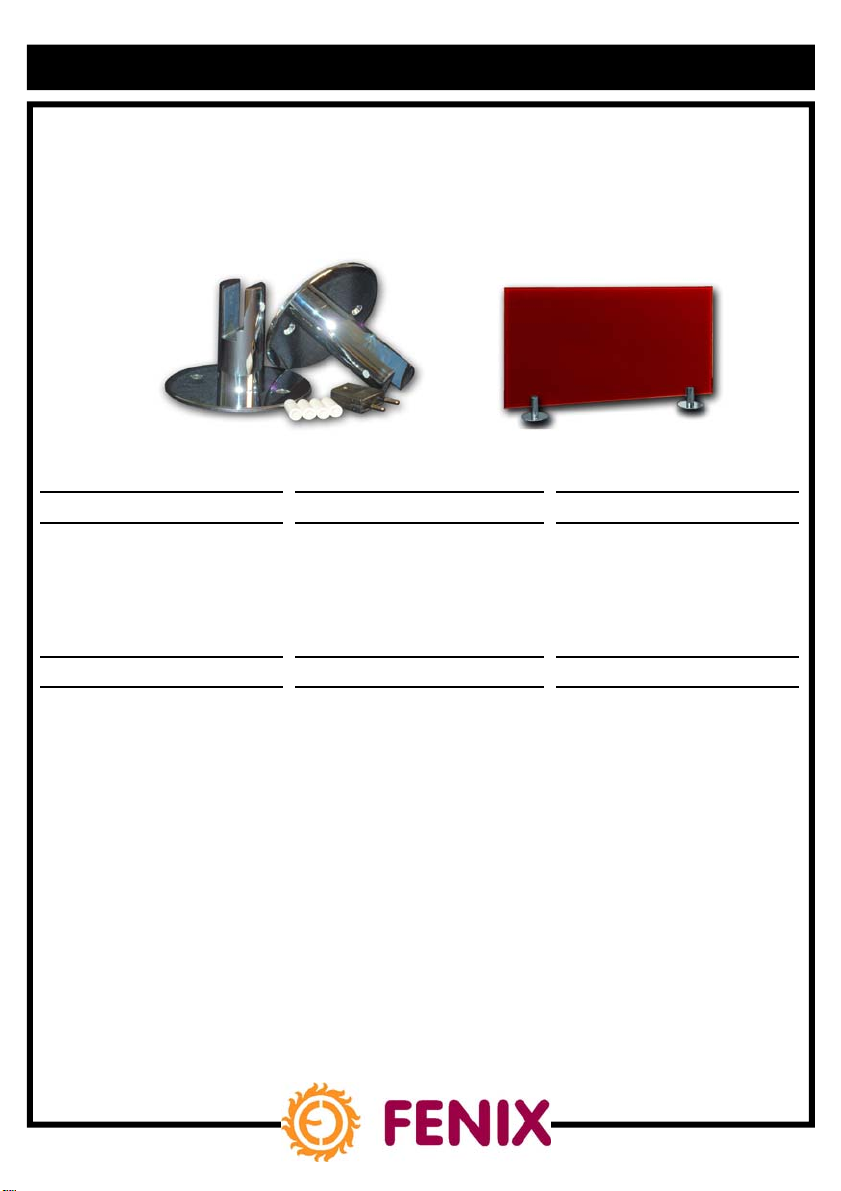
1. Použití:
Pro aplikace, u kterých nelze zavěsit GR
panel na stěnu (např. u prosklených
ploch).
1. Use:
For applications where the GR panel
cannot be hung on the wall (e.g. in the
case of glass surfaces).
1. Verwendung:
Für die Anwendungen, bei denen nicht
möglich ist, die GR Platte an die Wand
anzuhängen (z.B. bei Glasflächen).
2. Obsah sady:
•
2 × chromová podpěra (průměr
podstavy 130mm)
•
4 × plastový kryt na konzoly GR
panelu
•
1 × síťová vidlice (instaluje se na
přívodní šňůru při využívání panelu
jeko přenosného topidla)
•
2x aretační šroub
2. Contents of the set:
•
2 × chromium support (base diameter
130mm)
•
4 × plastic cover for the GR panel
brackets
•
1 × mains plug (to be installed on the
supply lead if the panel is to be used
as a portable heater)
•
2 × adjustment screw
2.
Inhalt des Sets:
•
2 x Chromstütze
(Basisdurchmesser 130 mm)
•
4 x Kunststoffdeckungen für die
Konsolen der GR Platte
•
1 x Netzstecker (er ist auf die
Netzschnur zu installieren, wenn
die Platte als tragbares Heizgerät
verwendet wird)
•
2 x Stellschraube
Page 2

3. Způsob montáže:
Podpěry jsou určeny pouze pro typ GR a
pouze pro horizontální instalaci. (vložení panelu
do podpěr jeho delší stranou)!
GR panel se vloží do výřezu podpěr,
následně se podpěry k panelu zafixují
pomocí aretačních šroubů. Vzdálenost
podpěr od bočních hran panelu by
neměla být větší než 100mm u panelu
GR 300, 500 a 150mm u panelu GR
700, 900. Panel v podpěrách nelze
přemísťovat posuvem po podlaze—může
dojít k vysunutí z podpěry a poškození
panelu.
Vzdálenost spodní hrany panelu od
podlahy je 55mm.
Na konzole panelu se nasunou plastové
krytky. Panel je na podpěrách stabilní,
maximální povolený vychýlení z osy 15°.
Pro trvalé instalace doporučujeme podpěry fixovat k podlaze pomocí vrutů -
v podstavě jsou dva otvory o průměru
6mm pro vrut se zápustnou hlavou
(vruty nejsou součásti balení).
V případě montáže síťové vidlice nezáleží
na umístění pólů.
3. Method of installation:
The supports are intended only for use with the
GR type and only for horizontal installation
(insertion of the longer side of the panel into
the supports)!
The GR panel is to be inserted into the
slits in the supports; the supports are
subsequently attached to the panel using
the adjustment screws. The distance
between the supports and the side edge
of the panel shouldn’t exceed 100mm for
the GR 300, 500 panel and 150mm for
the GR 700, 900 panel. The panel when
placed in the supports cannot be moved
by sliding across the floor – the panel
can slide out from its supports and be
damaged.
The distance of the bottom edge of the
panel from the floor is 55mm.
Plastic covers are to be placed onto the
panel brackets. The panel is stable on
the supports; the maximum allowed
deflection from the axis is 15°.
For permanent installation, we recommend
attaching the supports to the floor using
screws – there are two openings with a
diameter of 6mm in the base for screws
with countersunk heads (these screws
aren’t included in the package).
If the mains plug is installed, there is no
restriction on how the poles may be
placed.
3. Montageart:
Die Stützen sind nur für den Typ GR und nur
für die horizontale Installierung bestimmt (die
Platte ist mit ihrer längeren Seite in die
Stützen einzusetzen)!
Die GR Platte ist in den Ausschnitt der
Stützen einzusetzen, nachfolgen sind die
Stützen zu der Platte mittels der Stellschrauben zu befestigen. Der Abstand
der Stützen von den Seitenkanten der
Platte sollte bei der Platte GR 300, 500
nicht 100 mm überschreiten und bei der
Platte GR 700, 900 sollte er 150 mm
nicht überschreiten. Die in den Stützen
eingesetzte Platte kann nicht durch
Verschiebung auf dem Fußboden transportiert sein – sie könnte sich aus der
Stütze lösen und sich beschädigen.
Der Abstand der Unterkante der Platte
vom Fußboden beträgt 55 mm.
Auf die Konsolen der Platte sind die
Kunststoffdeckungen einzusetzen. Die
Platte auf den Stützen ist stabil, die
zugelassene Höchstabweichung von der
Achse ist 15
Für die Dauerinstallation wird es empfohlen, die Stützen mittels Holzschrauben
zum Fußboden zu befestigen – in der
Basis befinden sich zwei Löcher mit
dem Durchmesser von 6 mm, die für
die Versenkschraube bestimmt sind (die
Schrauben stellen keinen Bestandteil der
Lieferung dar).
Bei der Montage des Netzsteckers ist
o
.
4. Údržba:
Čištění chromových podpěr pomocí
přípravků neobsahujících pevné částice
(abraziva).
4. Maintenance:
The chromium supports may be cleaned
using preparations which do not contain
solid particles (abrasives).
4. Wartung:
Die Chromstützen sind mittels partikelfreier Mittel (ohne Scheuerpartikel) zu
reinigen.
Fenix Trading s.r.o.
tel.: +420 584 495 304, fax: +420 584 495 303
e- mail: fenix@fenixgroup.cz , http://www.fenixgroup.cz
Slezská 2, 790 01 Jeseník
 Loading...