

Page 1
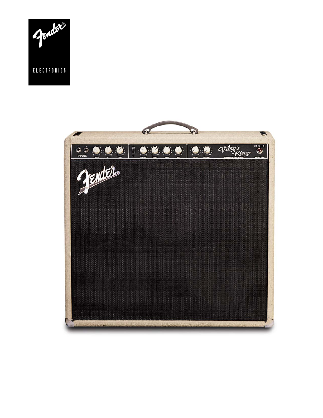
VIBRO-KING
CUSTOM SHOP SERIES
SERVICE MANUAL
Fender Musical Instruments Corp.
7975 North Hayden Road Scottsdale, AZ 85258
Page 2

VIBRO-KING
(This is the model name for warranty claims)
SERVICE MANUAL
JUNE 1994 REV A
TYPE CSR 4
IMPORTANT NOTICE:
The information contained herein is CONFIDENTIAL and PROPRIETARY to Fender Musical Instruments Corp. It is
disclosed solely for use by qualified technicians for purposes of equipment maintenance and service. It is not to be
disclosed to others without the expressed permission of Fender Musical Instruments Co. All specifications subject to
change without notice.
For warranty repair service, only Fender specified part numbers are to be used. It is recommended they also be used
for post-warranty maintenance and repair.
Parts marked with an asterisk (
and SAFETY requirements. DO NOT USE A SUBSTITUTE!
A coded naming convention is used in the description of certain parts. The codes and what they mean are as follows:
CAPACITOR CODES HARDWARE CODES
CAP AE = Aluminum Electrolytic BLX = Black Oxide
CAP CA = Ceramic Axial CR = Chrome Plated
CAP CD = Ceramic Disk HWH = Hex Washer Head
CAP MPF = Metalized Polyester Film M = Machine Screw
CAP MY = Mylar NI = Nickel Plated
CAP PFF = Polyester Film/Foil OHP = Oval Head Phillips
RESISTOR CODES
RES CC = Carbon Comp SMA = Sheet Metal "A" Point
RES CF = Carbon Film SMB = Sheet Metal "B" Point
RES FP = Flame Proof SS = Stainless Steel
RES MF = Metal Film TF = Thread Forming
RES WW = Wire Wound ZI = Zinc Plated
*) indicate the required use of that specific part. This is necessary for RELIABILITY
PB = Particle Board
PHP = Pan Head Phillips
PHPS = Pan Head Phillips Sems
Page 3

VIBRO-KING
THEORY OF OPERATION
J1 and J2 are summed by R11 and R12. These 10K Ω resistors are a lower than usual value for a tube
amplifier. This value was chosen for two reasons. 10K Ω is smaller than 33K Ω or 68K, Ω therefore the
amplifier will produce less noise at high volume settings. Secondly, when linking two or more amplifiers a
common trick is to plug the guitar into Input 1 and use Input 2 as the output to the next amplifier. With 68K
Ω resistors, 1/10
After the input resistors, the signal is split and fed to V1A and V2A. V1A serves as a preamp for the
Reverb Drive, or Dwell control. The Dwell control feeds V3, a small power tube which drives the Reverb.
V2A is a Cathode-Follower circuit which creates a low impedance, isolated (from the input) signal to drive
the Mix control (R2).
V2B amplifies the Reverb return (sense) signal and sends it to the Tone control (R3). High frequencies are
sent (shunted) to ground via C17. Varying R3 will move the wiper closer to or further from C17, thus
making the Reverb brighter (Clockwise) or duller (Counterclockwise). The Reverb signal then sums with
the Dry signal at the Mix control (R2).
After the Mix control, the signal travels to the Send jack (J3) of the Effects Loop. The signal is then
Normaled to the Return jack (J4) and drives V4A. This configuration allows the Reverb functions of the
Vibro King to be sent out to other amplifiers (via the Send jack). It also enables a player to insert a delay
unit between the reverb and the amplifier for a Rock-A-Billy type effect. A Volume pedal can also be
inserted to control the Guitar and the Reverb.
th
of the signal is lost with each link.
The V4A circuit contains the Fat switch (S1). The Fat switch connects C4 to ground to provide a 3dB
increase in gain, mostly in the low and mid frequencies. R17 is there to prevent “popping” of the Fat switch
when actuated. NOTE: the Fat switch may pop the first time it is switched. This is due to the warmup/stabilization cycle of the tube.
The Volume control R4A is linked to R4B. R4B reduces the gain of the Reverb at high volume levels. This
allows adjustment of the Volume without readjusting the Reverb Mix control.
From the Volume control (R4A), the signal is fed to V4B, the Tone control driver section. The signal leaves
the tone controls through the Treble control (R5), and is fed to the Vibrato and Phase Inverter circuits.
V6B is a low frequency oscillator. The Speed control (R8) varies the oscillation frequency. V6A is the Neon
Lamp driver. The lamp flashes faster or slower based on the position of the Speed control (R8). The
brightness of the neon bulb is sensed by two LDRs (Light Dependent Resistors) in parallel. The resistors
connect to the Intensity control (R9) which varies the amount of attenuation. Because the Vibrato circuit
connects to the amplifier directly after the Treble control, the high frequencies will attenuate before the
bass frequencies. This simulates a rotating speaker effect.
(TROUBLESHOOTING TIP: If the Vibrato does not function, first check the footswitch jack. The switching
part of the jack serves to short one side of R57 to ground. If R57 is not grounded, the Vibrato will not
operate.
If the Vibrato exhibits a clicking sound, the problem is caused by the position of the neon bulb in relation to
the LDR’s. Adjust the bulb by gently pulling on the leads. Test and repeat as necessary.)
Page 4

VIBRO-KING
THEORY OF OPERATION (CONT)
The signal then feeds the Phase Inverter (V5), which is a classic style split-load type, used without
feedback.
The output tubes (5881/6L6WGC) are arranged in a push-pull configuration that will produce sixty (60)
watts into two (2)Ω.
BIAS PROCEDURE: The bias, measured at pin 5 of V7 or V8 should be set to –46Vdc. However, the
Bias need not be measured to be accurately set. To set the Bias without removing the chassis, set the
Volume knob between 1-1/2 to 2. (The Bias control is located on the under side of the chassis, next to the
power cable.) Adjust the Bias so the amp produces the maximum Hiss. Strum a full chord and let ring.
Now, turn the Bias control back just to the point that the sound of the guitar loses warmth and sustain.
Then increase it slightly. This will ensure minimum crossover distortion and the best sound.
PARTS LIST
PRINTED CIRCUIT BOARD ASSEMBLY
QTY PART # DESCRIPTION REFERENCE DESIGNATION
1 080083 BULB NEON TYPE A2B (USED WITH PHOTOCELLS)
2 031069001 CAP AE RDL 10uF 100V 20%LL C23,28
4 009512 CAP AE AX 22uF 25V 20% C4,24,25,41
6 024819 CAP AE AX 22uF 500V C31-35,38 (@ FILTER CAP PC)
2 026502 CAP AE AX 100uF 100V C3,22 (C22 @ PWR SUPPLY PC)
2 013638 CAP AE AX 220uf 285V C29,30 (@ FILTER CAP PC)
1 031780 CAP SLVR MICA 150pF 300V C7
1 007029001 CAP CD 220pF 1000V 10%LL C36
1 020917001 CAP CD 250pF 1000V 10%LL C16 (@R2-3)
4 024824 CAP MPF RDL .01uF 630V 10% C11,17,(@R3), 38,39
3 024835 CAP MPF RDL .022uf 630V 10% C9,26,27
5 024846 CAP MPF RDL .1uF 630V 10% C2,15,18,12
1 024861 CAP MPF RDL .22uF 250V 10% C5
1 026202001 CAP PFF RDL .0022uF 600V LL C1
1 026204 CAP PFF RDL .0068uF 600V C6
1 033620001 CAP PFF RDL .47uF 100V 10% LL C10
1 064089001 DIODE 1N4003 LL CR5
4 026730001 DIODE 1N4006 800V LL CR1-4
2 029690001 DIODE HV 3KV 200mA LL CR7,8
2 038553 PHOTOCELL CDSE (LDR) (2 PCS IN PARALLEL, NO BULB)
2 026368001
1 9901218221
6 026549001 RES CF 1/2W 5% 1.5K R14,20,23,33,34,41
1 026493001 RES CF 1/2W 5% 2.7K LL R55
1 036955001 RES CF 1/2W 5% 6.8K LL R37
4 025113001 RES CF 1/2W 5% 10K LL R11,12 (@INPUT JACKS), 57,59
2 025832001 RES CF 1/2W 5% 22K LL R17,61,(@R10 BIAS POT)
1 041278001 RES CF 1/2W 5% 39K LL R26
5 025116001 RES CF 1/2W 5% 100K LL R24,44,49,56,68
6 025117001 RES CF 1/2W 5% 220K LL R31,32,40,48,64,65,73
2 041279001 RES CF 1/2W 5% 270K LL R53,54
3 036957001 RES CF 1/2W 5% 470K LL R15,21,42
6 9901251021 RES CF 1/2W 5% 1M LL R13(@INPUT JACKS) R18,25,28,51,52
3 041280001 RES CF 1/2W 5% 2.2M LL
1 037663001 RES CF 1/2W 5% 10M LL R50
3 *
036468001
1 027352001 RES FILM 1W 5% 91K LL
6 027353001 RES FILM 1W 5% 100K LL R16,19,22,30,43,47
1 036351001
1 041269001 RES CF 2W 5% 1.2K LL R66 (@ FILTER CAP PC)
RES CF 1/2W 5% 100Ω LL
RES CF 1/2W 5% 820Ω LL
RES MOX FP 1W 470 Ω LL
RES FILM 2W 5% 100Ω LL
R62,63
R27
R45,46,58
R35(@V8), 36(@V7), 60
R29
R70 (@V3)
Page 5

VIBRO-KING
PRINTED CIRCUIT BOARD ASSEMBLY (CONT)
QTY PART # DESCRIPTION REFERENCE DESIGNATION
1 041268001 RES CF 2W 5% 10K LL R67 (@ FILTER CAP PC)
1 036923
1 047057 RES WW BT 5W 25K R38 (@FILTER CAP PC)
1 * 028503
RES WW 5W 10% 680Ω
THERMISTOR 10 Ω 5A C60-11
CHASSIS ASSEMBLY
QTY PART # DESCRIPTION REFERENCE DESIGNATION
1 018002 BUSHING SNAP 5/16X17/32 BLK
1 021560 BUSHING SNAP 5/8X27/32 BLK
1 026038 BUSHING SR .625X.062X37/94 BLK (@ POWER CABLE)
1 031105 CABLE ASSY PWR .187+.250 120V (100/120V ONLY)
1 036486 CHOKE L1
2 031091 CLAMP TUBE (277H-1) (@V7,8)
1 032219 COLLAR-PILOT LIGHT
1 017502 CONTROL 10K LIN SCREW ADJ (BIAS ADJUST)
1 041264 CONTROL B5 MEG LIN R8 (SPEED CONTROL)
6 041266 CONTROL DUAL B500K LIN R1,2,4A/B,5,6,9
2 041265 CONTROL DUAL B50K LIN R3 (TONE), R7 (MID)
1 036702 FUSE HOLDER 3AG FINGER GRIP (100/120V ONLY)
1 036703 FUSEHOLDER 5mm FINGER GRIP (220/230/240V ONLY)
1 026559 FUSE TD 1-1/4X1/4 250V 3AMP F1 (100/120V ONLY)
1 013115 FUSE TD 20mmX5mm 250V 2AMP F1 (220/230/240V ONLY)
1 021741 HOLDER DIAL LITE ASSEMBLY PILOT
1 020773 INSULATOR DUAL PHONO JACK (@ REVERB DUAL PHONO JACK)
1 041469 INSULATOR FILTERCAP PC
1 023760 JACK PHONE 3/CD DCC 14B J5 (FOOTSWITCH JACK)
4 068270 JACK PHONE TIP SHUNT L12A 3/8L J1,2,4,7
2 021626 JACK PHONE 2/CD SOC L11 3/8” L J3.6
1 020772 JACK PHONO DUAL CHS MT (REVERB JACK)
1 025718 JEWEL #20 PILOT LITE
9 041263 KNOB VINTAGE CREAM
1 031625 NUT HOLDER PILOT LIGHT 1-16/27
4 022004 NUT KEPS #8-32X1/4 PHP BLX
2 023580 SOCKET TUBE 8 PIN (@V7,8)
2 032806 SCRW TF 6-32X1/4 PHP BLX (GROUND LUG MOUNT)
1 040909 PANEL FRONT ALUM VIBRO-KING
1 041220 PANEL REAR ALUM VIBRO-KING
1 021642 PILOT LIGHT #T47
6 041267 SOCKET TUBE 9PIN PORCEL W/SHLD (@V1-6)
5 025936 STANDOFF NYLON PCB SNAPIN 3/8”
1 037835 SWITCH SLIDE SPST
2 036570 SWITCH TOGGLE DPST W/NUTS S2,3 (POWER/STANDBY)
2 039214 TUBE VACUUM 5881/6L6WGC V7,8
5 013341 TUBE VACUUM 7025/12AX7
1 041255 TUBE VACUUM EL84 V3
8 022319 WSHR FLAT 1/4X9/16NI
3 022327 WHSR FLAT 8X7/16 NI
4 9904300100 WSHR LCK INTL 3/8X.681X.032 ZI (J1,2,6,7)
9 024049 WSHR LCK INTL 5/16X.600X.06 ZI
8 026401 WSHR SHLDR FIB 3/8X5/8 (FIBER WASHER)
1 036485 XFMR OUTPUT T2 (OUTPUT XFMR)
1 024038 XFMR OUTPUT 10W SE T3 (REVERB XFMR)
1 026554 XFMR PWR MUTI VOLT (100/120/230/240V)
R69
TH1
SW1 (FAT SWITCH)
V1,2,4,5,6
CABINET ASSEMBLY
QTY PART # DESCRIPTION REFERENCE DESIGNATION
1 040760 CAB ASSY VIBRO KING (COMPLETE CABINET)
1 040885 BACK ASSY UPPER VIBRO KING
1 040886 BACK ASSY LOWER VIBRO KING
1 031849 BAG-REVERB SPRING UNIT (BAG ONLY)
1 025722 CABLE ASSY REVERB 1100mm
Page 6

VIBRO-KING
CABINET ASSEMBLY (CONT)
QTY PART # DESCRIPTION REFERENCE DESIGNATION
1 038566 CABLE ASSY SPKR RT ANG 13-1/2” (SPEAKER CABLE)
1 036784 Handle molded brown
2 024851 Leg 19” amp
1 036795 Nameplate 62 fender
2 021998 Nut flex lock 10-32 w/ nylon in (TILT BACK LEG MOUNT)
1 064063 REVERB UNIT 4 SPRING 4AB3C1B (PAN)
2 037210 SCREW SMA 2X3/8 OHP NI (LOGO MOUNT)
8 037952 SCRW SMA #6X1 OHP NI (BACK BOARD MOUNT)
4 037247 SCRW M 8-32X1 OHP NI (HANDLE MOUNT)
4 022236 SCRW M 8-32X3-1/4 OHP NI CONE (CHASSIS MOUNT)
2 022277 SCRW M 10-32X1-1/2 OHP NI (TILT BACK LEGS MOUNT)
2 031344 SCRW SMA 10X3/4 OHP NI (LEG STOP MOUNT)
12 043331 SCRW M 10-32X5/8 HWHS BLX (SPEAKER MOUNT)
3 036457
2 024752 STRAP CHASSIS 4-1/2”
8 037215 WSHR C’SNK #6 NI (BACKBOARD ASSY MOUNT)
6 022319 WSHR FLAT 1/4X9/16 NI (TILT BACK LEGS MOUNT)
2 024646 WASHER LEG STOP TN
2 022285 WSHR SP LCOK 1/4X.493 ZI (TILT BACK LEG MOUNT)
QTY PART # DESCRIPTION REFERENCE DESIGNATION
1 041273 FTSW ASSY 2 BTTN VIB/FAT (COMPLETE FOOTSWITCH)
1 021691 BUSHING SR .500X.100X7/16 BLK
1 022665 COVER CUP DUAL FTSW ASSY
1 013172 PLUG PHONE 3 CONDUCTOR 238 RA
2 024042 SWITCH SPST PUSH BUTTON S1,2
2 022293 WSHR FLAT .473X.750 NI
SPEAKER 10” 8 Ω 30 WATTS
FOOTSWITCH ASSEMBLY
MISCELLANEOUS
QTY PART # DESCRIPTION REFERENCE DESIGNATION
1 041223 MANUAL OWNERS VIBRO KING
1 041727 SCHEM REDUCED VIBRO KING
VIBRO-KING 212 SPEAKER ENCLOSURE
QTY PART # DESCRIPTION REFERENCE DESIGNATION
4 026566 CORNER 2 HOLE W/TAB NI
4 026568 CORNER 3 HOLE NI
1 047402 GRILLE ASSY VIBRO KING 212 (COMPLETE GRILLE)
2 025395 HANDLE CAP 1 HOLE NI
1 037121 HANDLE STRAP BRN (NO INSERT)
1 032524 INSERT HANDLE (SPRING STEEL)
1 021956 JACK PHONE OPEN CIRCUIT 11
2 022244 SCRW M 10-32X1-1/8 OHP NI (HANDLE MOUNT)
2 047279
SPEAKER 12” 8 Ω CEL VINTAGE
(CELESTION VINTAGE 30 T3903
Page 7

Page 8

Page 9

 Loading...