

Fender Pro-Reverb Service Manual
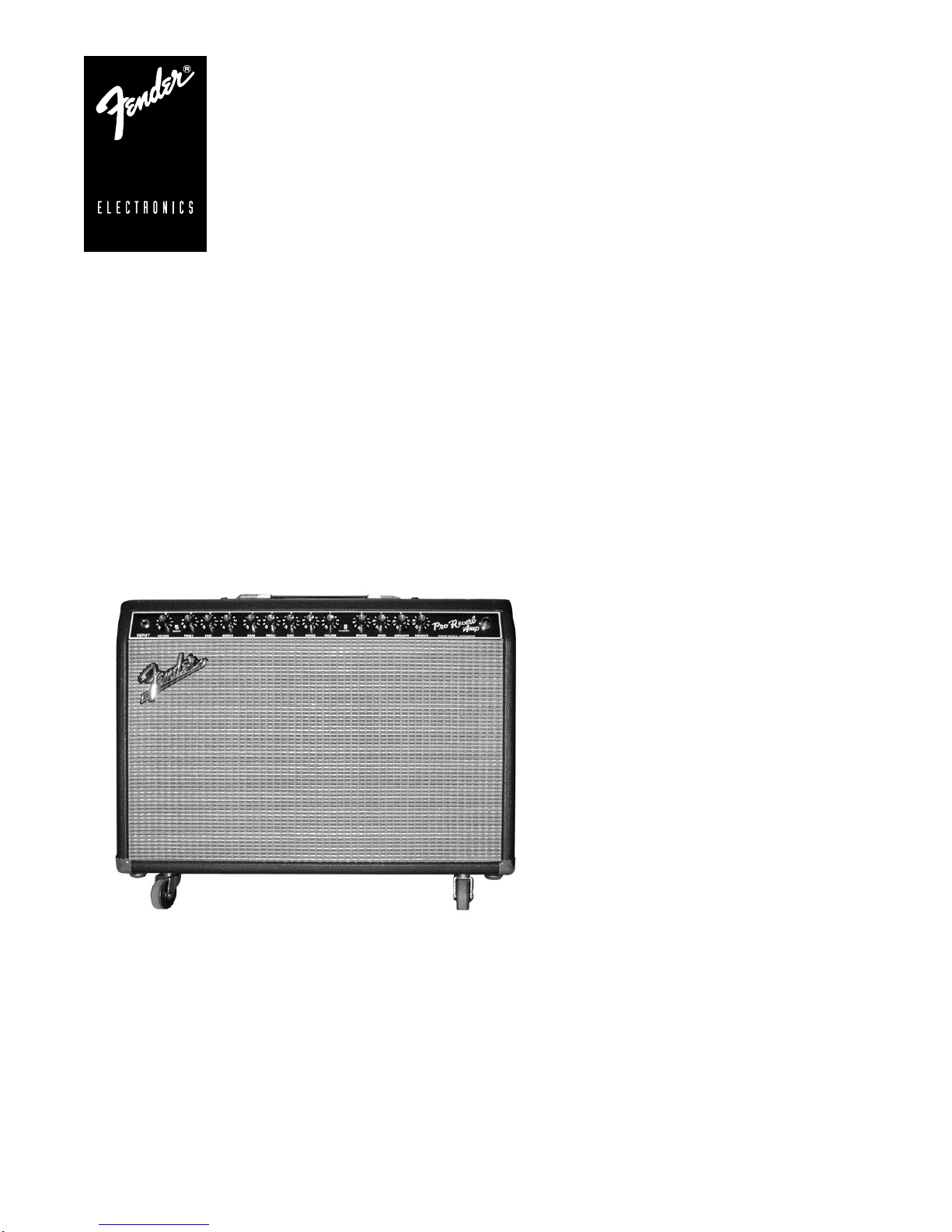
PRO-REVERB AMP
p/n 021-5500-000 (120V)
SERVICE MANUAL
CONTENTS:
Specifications
Service notes
Parts lists:
PCB assy-main
PCB assy rear panel
Chassis assy
Cabinet assy
End item
Drawings
Notices
Fender Musical Instruments Corp. 7975 North Hayden Road Scottsdale, AZ 85258

PRO-REVERB AMP
(This is the model name for warranty claims)
SERVICE MANUAL
JUNE 2001
IMPORTANT NOTICE:
The information contained herein is CONFIDENT IAL and PROPRIETARY to Fender Musical Instruments Corp. It is
disclosed solely for use by qualified technicians for purposes of equipment maintenance and service. It is not to be
disclosed to others without the expressed perm ission of Fender Musical Ins truments Co. All s pecifications subjec t to
change without notice.
For warranty repair service, only Fender specified part numbers are to be used. It is recommended they also be used
for post-warranty maintenance and repair.
*
Parts marked with an asterisk (
SAFETY requirements. DO NOT USE A SUBSTITUTE!
A coded naming convention is used in the description of certain parts. The codes and what they mean are as follows:
CAPACITOR CODES HARDWARE CODES
CAP AE = Aluminum Electrolytic BLX = Black Oxide
CAP CA = Ceramic Axial CR = Chrome Plated
CAP CD = Ceramic Disk HWH = Hex Washer Head
CAP MPF = Metalized Polyester Film M = Machine Screw
CAP MY = Mylar NI = Nickel Plated
CAP PFF = Polyester Film/Foil OHP = Oval Head Phillips
RESISTOR CODES
RES CC = Carbon Comp SMA = Sheet Metal "A" Point
RES CF = Carbon Film SMB = Sheet Metal "B" Point
RES FP = Flame Proof SS = Stainless Steel
RES MF = Metal Film TF = Thread Forming
RES WW = Wire Wound ZI = Zinc Plated
) indicate the required use of that specific part. This is necessary for RELIABILITY and
PB = Particle Board
PHP = Pan Head Phillips
PHPS = Pan Head Phillips Sems

PRO-REVERB AMP
SPECIFICATIONS
Product Release No.: PR 448 (This is not a model number)
Part Number: 120V Version : 21-5500
240V Aus : 21-5530
230V UK : 21-5540
230V Eur : 21-5560
100V : 21-5570
Power Requirements: 325W
Power Amp Section:
Power Output: 50 Watts RMS (High Output)
12.5 W RMS (Low Output)
1kHz sine wave into 8Ω @<5% THD (Presence @ “1”)
Input impedance: 1MΩ
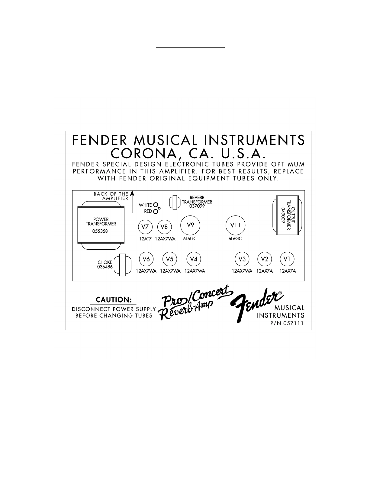
Tubes: Two 6L6GC (P/N 053980)
Two 12AX7A (P/N 023572)
Five 12AX7WA (P/N 013341)
One 12AT7 (P/N 023531)
Fuses: F200: F3A 250V (100V, 120V units)
T2A 250V (230V, 240V units)
F201: T5A 250V (Internal filam ent fuse on 230V, 240V units)
F1 & F2: T 100mA 250V (all units)
Speaker Complement: One 8 Ω Jensen C12N 12" (P/N 057065)
Footswitch: Four-Button: Channel, Effects, Reverb, Tremolo (P/N 057025)
Dimensions: Height:17 3/8" (44.3 cm)
Width: 25 3/8" (64.7 cm)
Depth: 12 27/32" (32.8 cm)
Weight: 75 lbs. (34 kg)
Product specifications are subject to change without notice
PRO-REVERB AMP
SERVICE NOTES
1. CHASSIS REMOVAL is accomplished by first removing eight (8) screws fr om t he top, and one (1)
screw from each side of the cabinet;disconnect r everb and speaker wires, then slide the chassis
toward the rear.
2. TUBE CHART:
3. OUTPUT TUBE BIAS & BALANCE ADJUSTMENTS
A. Warm up the amp for 2 m inut es with ST AND BY OFF and the OUTPUT POWER set to FULL.
Set SPEED and INTENSITY TO “ 1 ” and make sure TREMOLO is OFF. Flip the STAND BY switch
to the UP position.
B. Remove the bias controls cover box.
C. Set BIAS: with a DC voltmeter m easure VDC between GND and V9 test points. Adjust BIAS for
.03 VDC (30mVDC).
D. Set BALANCE: measure the VDC bet ween V9 and V11 test point s. Adjust BALANCE for zero
(0) VDC.
E. Replace the bias controls cover box.

PRO-REVERB AMP
PARTS LIST
NOTE: SHADED ITEMS ARE FOR REFERENCE ONLY
PRINTED CIRCUIT BOARD ASSEMBLY – MAIN
QTY PART # DESCRIPTION REFERENCE DESIGNATION
REF 0057014000 SVC. DIA., COMB. PRO-TUBE AMPS
1 0057015000 PCB FAB MAIN, PRO-TUBE AMPS
2 0038690001 CAP AE AX 1.0uF 100V 20% C17 C37
4 0025960001 CAP AE AX 22uF 16V 20% C8 C29 C34 C111
3 0024819000 CAP AE AX 22uF 500V +50%-10% C203 C206-207
1 0038693001 CAP AE AX 47uF 16V 20% C1
4 0024820000 CAP AE AX 47uF 350V 20% C201-202 C204-205
2 0028494000 CAP AE RDL 1000uF 35V 20% C212-213
2 0031040000 CAP AE RDL 100uF 100V 20% C208-209
2 0028482003 CAP AE RDL 220uF 50V 20% C210-211
2 0036954003 CAP AE RDL 22uF 63V 20% C33 C216
1 0020883002 CAP CD 10pF 1000V 10% C31
2 0051408003 CAP CD 47pF 500V 5% C7 C101
1 0069724002 CAP CD 100pF 1000V 10% C105
1 0051405003 CAP CD 120pF 500V 5% C19
2 0020917002 CAP CD 250pF 1000V 10% C4 C22
1 0051458003 CAP CD 470pF 500V 10% C32
3 0025951002 CAP CD 750pF 1000V 10% C14 C16 C18
1 0025995002 CAP CD 8200pF 1000V 20% C200
2 0034788003 CAP CD .1uF 50V 20% .15” cut C224-225
3 0027272003 CAP MPF .047uF 63V 10% C218 C220 C223
1 0027280003 CAP MPF .15uF 63V 10% C217
2 0027281003 CAP MPF .22uF 63V 10% C215 C221
2 0027286003 CAP MPF .47uF 63V 10% C219 C222
1 0033477003 CAP MPF .68uF 63V 10% C11
3 0024823000 CAP MPF RDL .01uF 400V 10% C23 C103 C110
6 0024833000 CAP MPF RDL .022uF 400V 10% C3 C9 C12 C21 C108-109
10 0024845000 CAP MPF RDL .047uF 400V 10% C2 C6 C10 C13 C15 C24-25 C30 C116-117
3 0024853000 CAP MPF RDL .1uF 250V 10% C100 C102 C104
7 0024854000 CAP MPF RDL .1uF 400V 10% C5 C20 C36 C112-115
2 0024855000 CAP MPF RDL .1uF 630V 10% C106-107
1 0024876000 CAP MPF RDL .68uF 250V 10% C27
1 0037040002 CAP PFF .0033uF 400V 10% C35
1 0037600000 CONTROL SNAPIN 100k B TAPER
2 0041507000 CONTROL SNAPIN 1M 10A TAPER
3 0047540000 CONTROL SNAPIN 250k 15A TAPER
2 0037597000 CONTROL SNAPIN 250k 30A TAPER
1 0041511000 CONTROL SNAPIN 250k B DUAL
1 0047031000 CONTROL SNAPIN 25k 30C TAPER
2 0041510000 CONTROL SNAPIN 25k B TAPER
1 0037601000 CONTROL SNAPIN 3M 10C TAPER
16 0026730001 DIODE 1N4006 800V 1A D100-101 D200-207 D210-215
R73 Reverb
R12 R37 Ch1volume Ch2volume
R10 R17 R35 Ch1bass Gain Ch2bass
R9 R34 Ch1treble Ch2treble
R148 Intensity
R109 Presence
R11 R36 Ch1mid Ch2mid
R141 Speed

PRO-REVERB AMP
PRINTED CIRCUIT BOARD ASSEMBLY – MAIN (cont)
QTY PART # DESCRIPTION REFERENCE DESIGNATION
18 0006260001 DIODE 1N4448 SIGNAL
2 0029690001 DIODE HV 3kV 200mA D102-103
1 0031017001 DIODE ZEN 1N5223B 2.7V 5% LL D224
3 0031635001 DIODE ZEN 1N5240B 10V 5% LL D5 D227 D238
6 0031019001 DIODE ZEN 1N5245B 15V 5% LL D2-3 D8-9 D112-113
2 0028119060 DIODE ZEN 1N5353B 16V 5W 5% D216-217
2 0041811060 DIODE ZEN 1N5368B 47V 5W 5% D208-209
6 0026000001 FSTN TAB MALE PCB MT .187X.032 P2-5 P216-217
20 0025802000 FSTN TAB MALE .250x.032 PCB MT P100-101 P200-215 P218-219
4 0031611000 IC OP-AMP DUAL PC4560 U1-4
2 0041261000 IC VOLT REF LM4040DIZ-10.0 U5-6
D1 D4 D6-7 D114 D223 D226 D228-229 D231237 D239-240
1 0037117000 JACK PCB MONO CLOSED CKT
1 0025933000 JACK PHONO DUAL PC MTG
J1 Input
J2 Reverb
1 0028039000 LED RED 5x5mm SLB-55VR3 D225
1 0030754000 LED RED T-1 3mm DIFFUSED D230
1 0036178000 SPACER LED .5x.1 BRN @D230
3 0036613000 RELAY DPDT DIP 24 VOLT 8.3mA K1-3
9 0025116001 RES CF 1/2W 5% 100k LL R3 R13 R20 R31 R52 R61 R71 R77 R111
2 0026368001 RES CF 1/2W 5% 100ohm LL R211-212
1 0025117001 RES CF 1/2W 5% 220k LL R202
1 0025113001 RES CF 1/2W 5% 10k LL R104
1 0025834001 RES CF 1/2W 5% 150k LL R146
2 0036957001 RES CF 1/2W 5% 470k LL R26 R144
1 0025115001 RES CF 1/2W 5% 82k LL R110
12 0024969001 RES CF 1/4W 5% 1.5k LL
8 0024997001 RES CF 1/4W 5% 100k LL
11 0024981001 RES CF 1/4W 5% 10k LL
R4 R14 R21 R43 R51 R62 R68-69 R114-115
R215 R238
R8 R147 R208 R220 R226 R230 R243 R249
R19 R25 R30 R41 R50 R60 R143 R207 R231233
1 0024937001 RES CF 1/4W 5% 10ohm LL R250
1 0024999001 RES CF 1/4W 5% 150k LL R100
5 0024985001 RES CF 1/4W 5% 15k LL R101 R155 R224 R229 R248
1 0024955001 RES CF 1/4W 5% 180ohm LL R227
1 0024986001 RES CF 1/4W 5% 18k LL R27
1 0024965001 RES CF 1/4W 5% 1k LL R81
15 0025069001 RES CF 1/4W 5% 1M LL
R1 R6 R15 R18 R38 R40 R46 R49 R63 R78 R82
R103 R106 R142 R153
8 0025059001 RES CF 1/4W 5% 220k LL R5 R16 R24 R53 R67 R75 R112-113
2 0024987001 RES CF 1/4W 5% 22k LL R39 R79
1 0025077001 RES CF 1/4W 5% 3.3M LL R76
4 0024989001 RES CF 1/4W 5% 33k LL R2 R33 R45 R102
2 0024977001 RES CF 1/4W 5% 4.7k LL R107 R145
1 0025079001 RES CF 1/4W 5% 4.7M LL R70
12 0025065001 RES CF 1/4W 5% 470k LL
R7 R23 R28-29 R64-65 R74 R214 R223 R234
R236 R246
1 0024961001 RES CF 1/4W 5% 470ohm LL R105
3 0024993001 RES CF 1/4W 5% 47k LL R22 R42 R44
1 0024962001 RES CF 1/4W 5% 560ohm LL R237
2 0028948001 RES CF 1/4W 5% 6.2k LL R80 R235
4 0024979001 RES CF 1/4W 5% 6.8k LL R154 R225 R228 R247
2 0025068001 RES CF 1/4W 5% 820k LL R222 R245
2 0024964001 RES CF 1/4W 5% 820ohm LL R32 R72
2 0029613001 RES CF 1/4W 5% 91k LL R108 R140
 Loading...