

Page 1

THE SOUND THAT CREATES LEGENDS
KEYBOARD
EXTENDED
RANGE
Two hundred
Owner,s Manual
P/N 048502
Page 2

INTRODUCTION
Your new Fender®KXR 200 keyboard amplifier is the result
of Fender's
®
ongoing dialog with many of today's top musicians. The KXR 200 uses state of the art technology to
deliver clear, resonant and most importantly...musical
sound.
The KXR 200 is actually much more than a keyboard amp.
With its heavy-duty Fender
®
Special Design speaker and
dual piezo-electric horn, it could actually be classified as a
self-contained, portable P.A. system. The KXR 200 is suitable for almost any musical instrument requiring full-range
reinforcement, for example, electronic keyboards,
acoustic/electric guitar, electric violin and also vocals.
Compact packaging and high output power make the KXR
200 the perfect full-range instrument amplifier for
rehearsal, studio or performances.
The preamp section of the KXR 200 features four independent channels. Channels one, two, and three each feature
a single 1/4 inch, high-impedance-input jack, a threeband equalizer, a channel volume control, an effects send
control and a reverb send control. Emphasizing on vocal,
channel four is equipped with a low impedance XLR jack in
addition to the 1/4 inch jack. Furthermore, channel four
also features a four-band equalizer centered around the
vocal frequencies, while still covering the whole audible
audio spectrum. Channel four is also equipped with a
channel volume control, an effects send control and a
reverb send control. In addition to the features mentioned
above, each channel also possesses an independent effects
loop insertion point on the rear panel. This feature makes
the KXR 200 even more versatile.
The KXR 200 is also equipped with a master section which
contains a master volume control, an effect return control, a
reverb return control, an effects send jack, an effects return
jack, and a line-out portion comprising of a 1/4 inch and
XLR jacks.
The KXR 200 keyboard amplifier was designed to give
years of reliable service under all conditions and is
equipped with a unique implementation of our exclusive,
defeatable DELTACOMP
DELTACOMP
TM
is engaged, it is practically impossible to
TM
compressor system. When
cause the power amplifier to clip (distort). With DELTA-
TM
COMP
, apparent compressor release time is kept short,
yet waveform distortion is kept to a minimum at low frequencies.
The selection of a Fender
®
amplifier will reward you with
years of quality music in a wide range of sonic possibilities.
This manual is designed to familiarize you with the features
and functions of your KXR 200 amplifier. Read this manual carefully so you will benefit from these features as soon
as you start using your new Fender
The built-in quality of a Fender
®
amplifier.
®
amplifier is the result of
over four decades of dedication in the combined skills of
the Fender
FENDER
®
design team. That’s why we proudly say,
®
... The Sound That Creates Legends.
Page 3
1
A
B
C
D
E
F
CHANNEL 1
INPUT
INPUT
VOLUME
5
010
VOLUME
5
010
0
-12 +120-12 +120-12 +12
CHANNEL 3
0
-12 +120-12 +120-12 +12
G
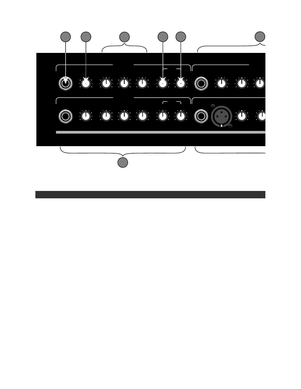
KXR 200 FRONT PANEL FUNCTIONS
CHANNEL 1 INPUT (1/4 INCH) - Plug-in connector for
A.
instruments. This balanced input can handle as much
as 8V R.M.S.
CHANNEL 1 VOLUME CONTROL - This control adjusts
B.
the preamplifier gain of channel 1. It works in conjunction with the Master Volume control ( item I) to set
the overall loudness of the amplifier for channel 1
only. Being a true “gain” control, it allows for the use
of a variety of microphones, keyboards or other instruments with differing output signal levels. Low-level
instruments generally require a higher Channel
Volume setting while “hotter” keyboards will require a
lower setting.
CHANNEL 1 EQUALIZER - This equalizer allows
C.
adjustments of the tonal characteristics of channel 1
before amplification. Each control provides a 12dB
boost or cut to bands of frequencies centered about
130, 540, and 4200 Hz. Note that all equalizer sections of the KXR 200 are designed so that if all center
frequencies are set at +12dB, a flat overall response
would be obtained. This is very useful if the signal
source is weak.
CHANNEL 1 EFFECTS SEND CONTROL - This control
D.
works in conjunction with the effects send jack (item R),
effects return jack (item S), and the effect return control (item J) to , respectively, allow a desired amount of
preamp signal to be massaged, and to control the
amount of return signal that has gone through an
HIGHMIDLOW
HIGHMIDLOW
SEND
REVERBEFFECTS
5
0105010
SEND
REVERBEFFECTS
5
0105010
INPUT
INPUT MIC
VOLUME
010
5
CHANNEL
MIDLOW
0
-12 +1 20-12 +1 2
VOLUME
5
010
LOW
-12 +
0
external effects device. The effects send control in conjunction with the effects send jack could be used to
drive another KXR 200 as a slave amp. This is done
by connecting the effects send jack, with a standard
guitar cord, to the effects return jack of another KXR
200. Note that each channel could be set to send a
different amount of signal to the effects bus.
CHANNEL 1 REVERB SEND CONTROL - This control
E.
works in conjunction with the reverb return control
(item K) to allow the amount of reverb to be mixed
with the dry signal. The amount of reverb-sent signal
is independent for each channel.
CHANNEL 2 AND 3 - These two channels are provid-
F,G.
ed for two additional instruments. All the controls and
jacks operate in the same manner as those in channel
1. When not in use, it is best to turn the channel volume, the effects send and the reverb send controls all
the way down to avoid any amplification of unwanted
noise. Likewise, when not in use, the equalizer sections should be kept flat ( i.e. all knobs should be set at
12 O’clock).
CHANNEL 4 - This channel operates in the same man-
H.
ner as the other three channels, but with the addition
of a few extra features: The XLR jack and an extra
band in the equalizer section. With the vocalist in
mind, the balanced, low impedance XLR jack provides
a suitable connection for a microphone. Furthermore,
the four-band equalizer was designed around the
Page 4

F
I
J
K
L
M
CHANNEL 2
HIGHMIDLOW
0
-12 +1 20-12 +1 20-12 +1 2
CHANNEL 4
VOLUME
5
010
LOW
-12 +12
LOW MID
0
-12 +12
0
SEND
REVERBEFFECTS
5
0105010
HIGHHIGH MID
0
-12 +12
0
-12 +12
H
vocal frequencies. With each control providing 12dB
of boost or cut, and centered about 125, 320, 1000
and 3200 Hz. If needed, this channel could also be
used for another instrument.
MASTER VOLUME CONTROL - This control adjusts the
I.
level of the signal coming out of the preamplifier section. This control is used in conjunction with the
Channel Volume controls to set the overall sound level
of the amplifier. In order to maximize headroom and
minimize noise, instruments with low-level output will
require a high Channel Volume setting and a low
Master Volume setting, while other instruments may
require a lower Channel Volume and higher Master
Volume setting. It is recommended that the Master
Volume control be set as high as possible for maximum DELTACOMP
TM
compressor range.
MASTER
VOLUME
5
010
5
0105010
5
0105010
SEND
REVERBEFFECTS
L.
M.
RETURN
REVERBEFFECTS
ON
OFF
DELTACOMP
TM
ON
POWER
KEYBOARD
EXTENDED
RANGE
Two hundred
N
PEAK LED INDICATOR - This LED comes on when
excessive signal levels are being sent to the power
amplifier. It illuminates on signal peaks that cause
clipping (distortion) with DELTACOMP
or for signal peaks that cause DELTACOMP
level (DELTACOMP
large percentage of the time, the dynamic range of the
system is reduced and the overall sound suffers. For
this reason, level controls should be adjusted so that
the yellow LED only flashes on occasional signal
peaks.
DELTACOMP
or de-activate the DELTACOMP
clipping of signal is not desired, then the
DELTACOMP
ing this button in.
TM
active). If the limiter is on for a
TM
SWITCH - This switch is used to activate
TM
circuitry should be engaged by push-
O
TM
not activated,
TM
TM
circuitry. If peak-
to reduce
J.
EFFECTS RETURN CONTROL - This control adjusts the
level of the signal coming into the power amplifier section from external effect devices. This is the master
control for all the Channel Effects Send controls. If not
in use, it is recommended that this control be set at 0
to avoid amplification of any unwanted signal.
REVERB RETURN CONTROL - This control adjusts the
K.
level of the reverb signal coming into the power amplifier from the reverb bus. The input to the reverb circuitry is the sum of the individual channel reverbs.
When not in use, it is recommended that this control
be set at 0 to avoid amplification of any unwanted signal.
N.
POWER LED INDICATOR - When this LED is illuminat-
ed, the KXR 200 is receiving power.
O.
POWER SWITCH - This switch turns the KXR 200 on or
off. When the switch is off, the amplifier is completely
shut down.
Page 5

KXR 200 REAR PANEL
LINE OUTPUT JACKS - Signal from each of the chan-
P,Q.
nels are combined with reverb and effects to form the
input to the power amplifier stage. The Line Outs are
wired from this point. The 1/4 Jack (Item P) and the
XLR jack (Item Q) provide easy connection paths from
the KXR 200 to any external devices, such as a slave
amp or a mixer. It is also useful for recording live performances. Note that inserting a plug into one of the
Line Outs jacks does not interrupt the normal internal
signal flow of the KXR 200.
EFFECTS SEND JACK - This jack is the output of the
R.
effects bus, where all the channels Effects Send are
combined. The signal coming out of this jack could be
used to drive an effects device, a slave amp, or as an
input to a mixer . Note that the signal coming out of
this jack is reverb-free.
POWER CORD - This amplifier is equipped with a
grounding type supply cord to reduce the possibility of
shock hazard. Be sure to connect it to a grounded AC
receptacle. The line cord should be connected to a
suitable power source, in accordance with the voltage
and frequency as shown by the power rating on the
rear panel. DO NOT ALTER THE AC (MAINS) PLUG.
NOTE: DO NOT BLOCK THE AIR FLOW TO THE
REAR PANEL; FOR EXAMPLE, BY BACKING THE
AMPLIFIER UP AGAINST A WALL. The rear panel
contains a heatsink that needs air flow to cool off the
amplifier. Blocking the air flow may result in equipment failure due to excessive heat building up inside
the chassis.
EFFECTS RETURN JACK - This jack inputs signal to the
S.
master section of the KXR 200 through the Effects
Return control (Item J). This jack can be used with the
Effects Send Jack (item R) as a patch point for mono
effect devices. This jack can also be used as the input
jack when the KXR 200 is used as a slave amp.
CHANNEL INSERT JACKS - These jacks are wired
T.
post-EQ and post channel volume control. By inserting
an external signal source into one of these jacks,
through a stereo jack wired to the tip and sleeve (with
the ring left floating), the appropriate channel’s EQ
and volume control are bypassed. By shorting the tip
of the inserting jack to its ring, the channel’s signal
and the externally input signal could be mixed together. The channel inserts can also serve as effects loop
points by using a stereo jack wired tip=effects send,
and ring=effects return. Note that the layout of the
insert jacks on the back panel is the mirror image of
the channels layout on the front panel.
WARNING : THIS EQUIPMENT MUST BE EARTH
GROUNDED.
COVERING CARE - UNPLUG THE POWER CORD
BEFORE CLEANING - The exclusive vinyl covering on
your cabinet has been especially designed for years of
lasting beauty. A very light, soapy solution on a
sponge may be used to remove dirt and residue that
may accumulate in the texture. Be careful as not to let
any liquid get inside the chassis or contact the operating surfaces.
Page 6

Channel 1
Balanced
High Z
Input
Channel 2
Balanced
High Z
Input
Channel 3
Balanced
High Z
Input
Balanced
Low Z
Channel 4
Inputs
Balanced
High Z
Low
Low
Low
Low
Equalizer
Mid
Equalizer
Mid
Equalizer
Mid
Equalizer
Low
Mid
KXR 200 BLOCK DIAGRAM
Channel 1
Volume
Hi
Insert
(Rear Panel)
Channel 2
Volume
Hi
Insert
(Rear Panel)
Channel 3
Volume
Hi
Insert
(Rear Panel)
Channel 4
Volume
Hi
Hi
Mid
Insert
(Rear Panel)
Effects
Send
Effects
Send
Effects
Send
Effects
Send
Reverb
Send
Reverb
Send
Reverb
Send
Reverb
Send
Main
Reverb
Effects
Effects
Send
Effects
Loop
(Rear Panel)
Reverb Circuit Reverb
Return
Effects
Return
Master
Volume
Line
Outputs
Deltacomp
TM
Power
Amp
Speakers
TROUBLESHOOTER‘S CHECKLIST
If the amplifier is set up but does not function, check the following items:
• Is the amplifier power cord plugged into an electrical outlet ?
• Is there power at the outlet ?
• Are all the control knobs properly set ?
• Are the controls knobs on the instrument properly set ?
• Is the instrument properly plugged into the KXR 200 ?
(Eliminate any effect pedals and try another guitar cord.)
If after checking all of the above, and the system is still not performing correctly,
consult your Authorized FENDER
®
Service Dealer.
Page 7

KXR 200 SPECIFICATIONS
PART NUMBER : 100V Version : 22-8572
120V Version : 22-8502
230V Version : 22-8562
240V Version : 22-8532
TYPE SPECIFICATION : PR 286
POWER REQUIREMENTS : 100V Version : 100VAC, 50/60Hz, 540W
120V Version : 120VAC, 60Hz, 540W
230V Version : 230VAC, 50Hz, 540W
240V Version : 240VAC, 50Hz, 540W
POWER AMPLIFIER SECTION :
POWER OUTPUT : 200W R.M.S.
RATED LOAD IMPEDANCE : 4Ω
DISTORTION AT 200 WATTS : Less than 1% @ 1kHz, below compression
Less than 1% @ 1kHz, maximum compression
SENSITIVITY : 1.03 Volts R.M.S.
INPUT IMPEDANCE : 22kΩ
TM
DELTACOMP
RANGE : 20dB.
PREAMP SECTION :
INPUT IMPEDANCE : XLR - 1.82kΩ
Phone - 18.2kΩ
Sensitivity for 200 watts : XLR - 2.9 mV R.M.S.
channel and master Phone - 29 mV R.M.S.
volume at maximum, all
tone control at “0”
THIS EQUIPMENT CONFORMS TO
THE FOLLOWING DIRECTIVES :
EMC 89/336/EEC AND LV 73/23/EEC
EQUALIZER : For 3-band-EQ sections :
+/- 12dB at 130, 540 and 4200 Hz.
For 4-band-EQ section :
+/- 12 dB at 125, 320, 1000 and 3200 Hz.
Sensitivity for channel 500 mV R.M.S. (-6dBV).
inserts, Master volume
at maximum setting
Sensitivity for 130 mV R.M.S. (-18dBV).
Master volume and FX
return control at max.
PHYSICAL SPECIFICATIONS :
HEIGHT : 29 - 3/4 inches w/o casters (75.6 cm)
32 - 1/8 inches with casters (81.6 cm)
WIDTH : 21 - 11/16 inches (55.1 cm)
DEPTH : 12 inches (30.5 cm)
WEIGHT : 88 lbs. (40kg)
SPEAKER COMPLEMENT : 15” Fender®Special Design (P/N 048769)
Dual piezo horn (P/N 028813)
WARNING : NO USER SERVICEABLE PARTS INSIDE,
REFER SERVICING TO QUALIFIED PERSONNEL ONLY.
TO PREVENT FIRE OR SHOCK HAZARD,
DO NOT EXPOSE THIS EQUIPMENT TO RAIN OR MOISTURE.
A PRODUCT OF:
FENDER MUSICAL INSTRUMENTS CORP.,
CORONA, CA 91720
 Loading...