

Page 1
A
B
C
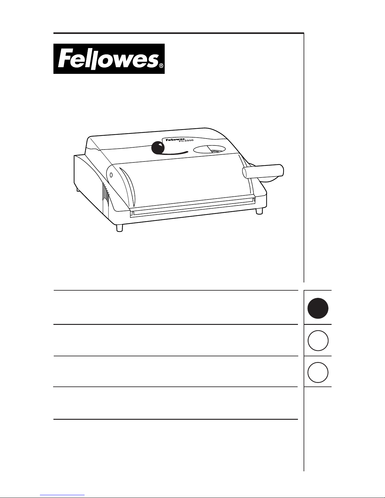
Operating Instructions
Mode d’emploi
Modo de empleo
Model/Modèle/Modelo: PC 2300
PC 2500
®
Page 2
A
B
C
2
®
3
6
1
10
7
8
4
2
9
11
12
13
14
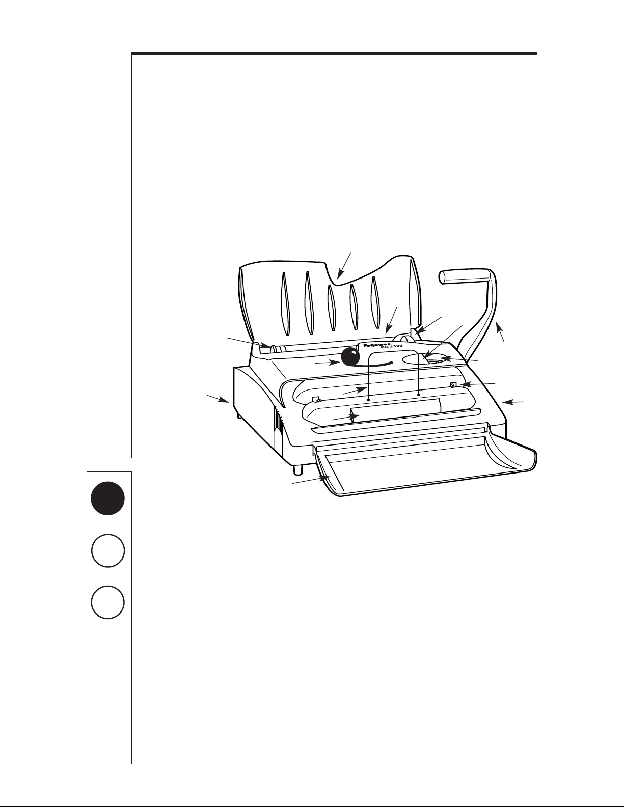
Equipment Parts
1. Punching Handle (PC 2300)
2. Punching Switch (PC 2500)
3. Punching Area
4. Adjustable Margin Guide
5. On/Off Switch
6. Sheet Supporter / Machine Cover
7. Coil Guide Selector
8. Machine Cover
9. Binding Wheel Power Switch
10. Electric Binding Wheel
11. Document Supporter
12. Crimping Claws
13. Crimping Lever
14. Paper Clippings Tray
Assembly
Assembly (PC 2300, only)
1. Attach the punching handle to the right side of the
machine by first aligning handle with square shaft on
machine. Press firmly.
NOTE: To operate correctly, the punching handle should
be positioned as illustrated below.
Once handle is fully attached, secure by inserting the
screw supplied.
Using the Binding
Machine
Adjusting the Punch:
Holes should always be centered between the top and
bottom of paper edge. To center hole, set the adjustable
margin guide. For best results, always first use several
"practice sheets" to set up margin guide.
Punching Holes: (PC 2300)
1. First, align the adjustable margin guide on the left-most
side of the punching area to correspond to appropriate
paper size. Once margin guide has been set to
correspond to appropriate paper size, insert paper into
punching area. Be sure all sheets are flush with margin
guide.
NOTE: a maximum 20 sheets can be punched at a time
2. Lower the handle to punch holes in paper.
3. Return punching handle to its original starting position
and remove sheets.
4. Repeat until all sheets and covers have been punched.
Punching Holes: (PC 2500)
1. First, align the adjustable margin guide on the left-most
side of the punching area to correspond to appropriate
paper size. Once margin guide has been set to
correspond to appropriate paper size, insert paper into
punching area. Be sure all sheets are flush with margin
guide.
NOTE: a maximum 12 sheets can be punched at a time
2. Turn machine on by depressing On/Off switch.
3. Depress punching switch and release.
4. Remove sheets from punching area.
5. Repeat until all sheets and covers have been punched.
5
Page 3
A
B
C
3
Determining Coil Size
Determining the appropriate coil size just got easier with
Fellowes’ handy, built-in coil guide selector. Or, if you happen
to know the number of sheets being bound, simply use the
chart below.
1. To select the optimum coil for binding, insert complete
document behind the adjustable coil guide selector
located near the punching area.
NOTE: Entire document, including covers, should fit snug
against coil guide selector to determine true coil size.
2. Read the corresponding coil size located left of the coil
guide selector.
3. Remove document from coil guide selector.
No. of Sheets Coil Size
35 6mm
45 7mm
60 8mm
80 10mm
100 12mm
110 13mm
120 14mm
Binding the
Document
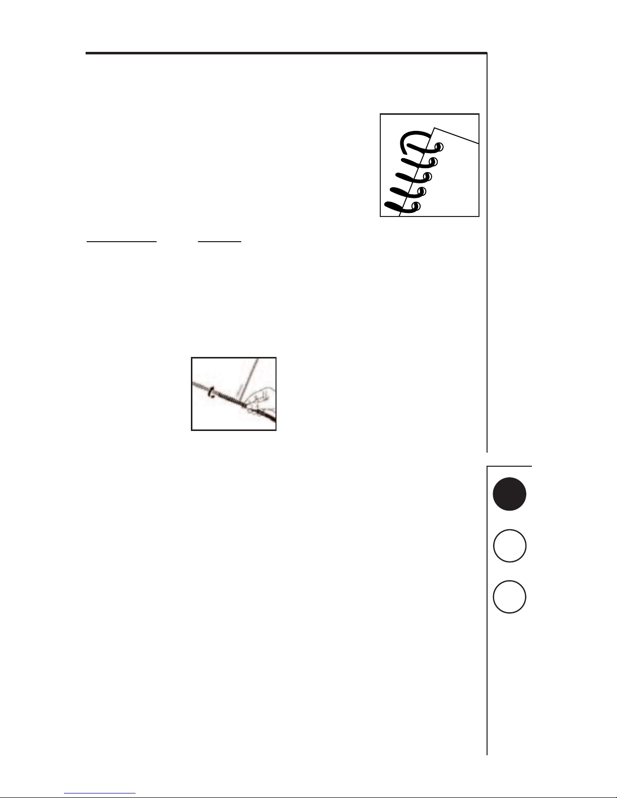
1. Align holes in paper and
cover. Place document on
flat surface. Starting at the
first hole on either end,
twist binding coil until
securing first 2-3 holes.
2. Turn on electric binding wheel by depressing power
switch.
3. Hold document next to binding wheel so that the first 23 holes already secured gently touch the wheel.
NOTE: The natural shape of the binding coil will
automatically feed from one hole to the next.
4. Remove document from binding wheel when coil has
passed through every hole. Your document is now
bound.
5. Turn off electric binding wheel by depressing power
switch.
Securing Your Bound
Document
Securing the document is
an important final step in
the process. To do so:
1. Insert document
behind document
supporter so that the
binding coil is
positioned on the
bottom. Each end of
the coil should be
positioned inside the
claws of the crimping area.
NOTE: Make certain claws are in an "open" position.
This is accomplished when the crimping lever is
positioned farthest to the right.)
2. Move crimping lever all the way to left. Note claws will
grab, cut and crimp the document.
3. Release document by returning crimping lever to
rightmost position.
4. Remove document from crimping area. Your document
is now secure.
Adding \ Removing Pages
from Bound Document
A unique feature of a Plastic Coil bound document is the ease
with which pages can be added \ removed. To do so:
1. Unlock secured document by "un-crimping" one end of
coil with fingers.
2. Remove coil from document by twisting coil.
3. Add \ Remove selected pages.
4. Re-assemble document.
Page 4
A
B
C
4
Emptying Paper Clippings
To empty, remove waste paper clippings tray located on backside of machine. The convenient handle makes grasping and
removal easy. To prevent potential clogging and jamming of unit, be sure to empty clippings frequently.
Specifications
PC 2300 PC 2500
Maximum binding length 11” 11”
(279mm) (279mm)
Maximum binding capacity 130 sheets 130 sheets
Maximum binding diameter 17mm 17mm
Maximum punching capacity 20 sheets 12 sheets
(at a time)
Number of holes punched 43 (4:1 pitch) 43 (4:1 pitch)
Dimensions 7
1
/8" x 181/2” x 193/4”7
1
/8" x 173/8” x 173/8”
(H x W x D) (181 x 470 x 502mm) (181 x 441 x 441mm)
Weight 31.9 lbs. 36.7 lbs.
(14.5 kg) (16.7 kg)
Warranty 1 year 1 year
Limited Warranty
Fellowes Manufacturing Company warrants all Binding Machines to be free from defects in material and
workmanship for a period of one year from the date of purchase by the original consumer. The exception to this
are the punching dies which are subject to wear. If any part is found to be defective during the warrant period,
your sole and exclusive remedy will be repair or replacement, at Fellowes’ option and expense, of the defective
part.
This warranty does not apply in cases of abuse, mishandling or unauthorized repair. ANY IMPLIED WARRANTY,
INCLUDING THAT OF MERCHANTABILITY OR FITNESS FOR A PARTICULAR PURPOSE, IS HEREBY LIMITED IN
DURATION TO THE APPROPRIATE WARRANTY PERIOD SET FORTH ABOVE. In no event shall Fellowes be liable for
any consequential or incidental damages attributable to this product. This warranty gives you specific legal
rights. You may have other legal rights which vary from state to state. To obtain service under this warranty on
machines purchased in the USA, return the machine prepaid to the address below. Please allow two weeks for
processing.
Return with machine:
• Copy of original sales receipt.
• A card stating your name, address, daytime telephone number, machine model and serial number, plus a brief
description of the problem.
For specific instructions on obtaining service under this warranty on machines purchased outside the USA, contact
the appropriate location listed below.
Warrantor: Fellowes Manufacturing Company
Page 5
Australia Benelux Canada France Germany Italy Japan Poland United Kingdom
Tullamarine, Vic Vianen, NL Markham, Ont. Rennes, I-V Garbsen, Han. Camerano, AN Tokyo Warsaw Doncaster, S. Yorks.
®
1789 Norwood Avenue, Itasca, Illinois 60143-1095 630-893-1600 Customer Service 1-800-945-4545 http://www.fellowes.com
Part No. 70985 © 2000 Fellowes Printed in U.S.A.
Contact For Service
Vos Contacts Fellowes
Sus Contactos Fellowes
United States 1-800-955-0959
Australia (In Melbourne) (03) 9330-3211
(Outside Melbourne) 1-800-331-177
Canada 1-800-665-4339
United Kingdom 01302-885 331
Japan +81-3-5496-2401
Benelux +31-(0)347-377988
Italia +39-071730041
Deutschland +49-5131-49770
France +33-(0)4-72-08-25-45
 Loading...