

Fein ASb 636, ASb 736 Operating Instructions Manual
ASb
636
To
be
handed
to
the
workshop!
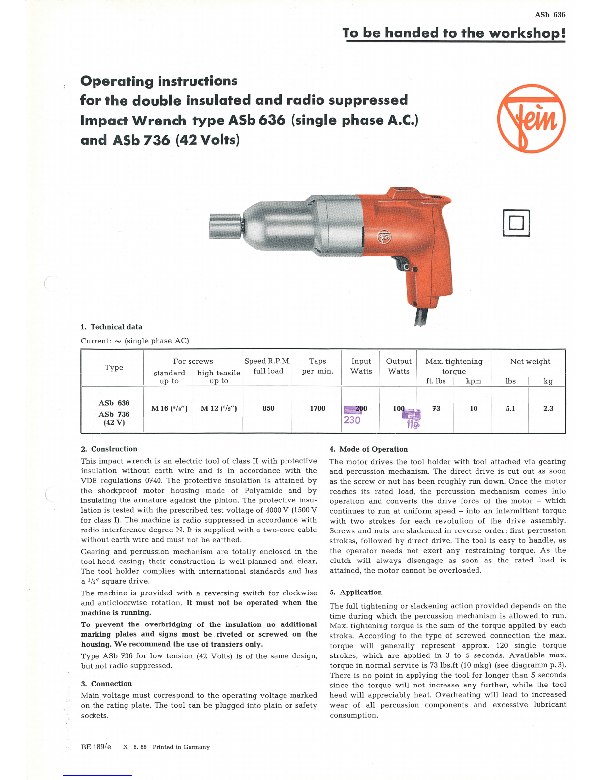
Operating
instructions
for
the
double
insulated
and
radio
suppressed
Impact
Wrench
type
ASb
636
(single
phase
A.C.)
and
ASb
736
(42
Volts)
1.
Technical
data
Current:
"'
(single
phase
AC)
For
screws
Speed
R.P.M.
Taps
Input
Output
Max.
tightening
Net
weight
Type
standard
I
high
tensile
full
load
per
min
.
Watts Watts
torque
up
to
up
to
ASb
636
M 16
(5/s")
M 12 (
1
/2")
850 1700
ASb
736
(42V)
2.
Construction
This
impa
ct
wrench
is
an
electric
tool
of
class
II
with
protective
insulation
without
earth
wire
and
is
in
accordance with
the
VDE
regulations
0740.
The
protective
insul
ation is
attained
by
the
shockproof
motor hous
ing
made
of
Polyamide
and
by
insulating
the
armature
against
the
pinion.
The
protective
insu-
lation
is
tested
with
the
prescribed
test
voltage
of
4000 V (1500 V
for
class
1).
The
machine
is
radio
suppressed
in
accordance
with
radio
interference
degree
N.
It
is
supplied
with a two-co
re
cable
without
earth
wire and
must
not
be
earthed.
Gearing
and
percussion
mechanism
are
totally
enclosed in
the
tool-head
casing;
their
const
ruction
is
well-planned
and
clear.
The
tool
holder
complies
with
international
standards
and
has
a
1
/2"
square
drive.
The
machine
is
provided
with a reversing
switch
for
clockwise
and
anticlockwise
rotation.
It
must
not
be
operated
when
the
machine
is
running.
To
prevent
the
overbridging
of
the
insulation
no
additional
marking
plates
and
signs
must
be
riveted
or
screwed
on
the
housing.
We
recommend
the
use
of
transfers
only.
Type
ASb
736
for
low
tension
(42
Volts)
is
of
the
same
design,
but
not
radio
suppressed.
3.
Connection
Main
voltage
must
correspond
to
the
operating
voltage
mark
ed
on
the
rating
plate.
The
tool
can
be
plugged
into
plain
or
saf
ety
sockets.
BE 189/e X 6.
66
Printed
in
Germany
ft.
lbs I kpm
lbs
I
kg
I
..
.
1~0
73 10
5.1
2.3
230
4.
Mode
of
Operation
The motor
drives
the
tool
holder
with
tool
attached
via
gearing
and percuss
ion
mechanism.
The
direct
dri
ve
is
cut
out
as
soon
as
the
screw
or
nut
has
been roughly
run
down.
Once
the
motor
reaches
its
rated load,
the
percussion
mechanism
comes
into
operation
and
converts
the
drive
force
of
the
motor -which
continues
to
run
at
uniform
speed -into
an
intermittent
torque
with
two
strokes
for
each revo
lution
of
the
drive
assembly.
Scr
ews
and
nuts
are
slackened
in
reverse
order:
first
percussion
strokes,
followed
by
direct
drive.
The
tool
is
easy
to
handle,
as
the
operator
needs
not
exert
any
restraining
torque.
As
the
clutch will
always
disengage
as
soon
as the
rated
load
is
attained,
the
motor
cannot
be
overloaded
.
5.
Application
The
full
tightening
or
slackening
action
provided
depends
on
the
time
during
which
the
percussion
mechanism
is
allowed
to
run.
Max.
tightening
torque
is
the
sum
of
the
torque
applied
by
each
stroke.
According
to
the
type
of
screwed conn
ection
the
max.
torque will
generally
represent
approx.
120
single
torque
strokes, which
are
applied
in 3 to 5 seconds.
Available
max
.
torque
in
normal
service
is
73lbs.ft
(10
mkg)
(see
diagramm
p.3).
There
is
no
point
in
applying
the
tool
for
longer
than 5 seconds
since
the
torque
will
not increase
any further, while
the
tool
head will
appreciably
heat.
Overheating
will lead
to
increased
wear
of
all
percussion
components
and
excessive
lubri
cant
cons
umption
.

63
35
Connecting
plan
Distributing
m_9in
switch
EZ 1-58
64
ns 36
61
60
58
59
57
..l..
ek
lj
j
~--
t
45 46
26
14
419
54 53
52
50
51
~
•l
~
j I I
~t
o
QQ
0
sr
.
• •
24 /
c/'
~
11
I
---
,r
·
'
---
~..&
.·
,
:lc
~
... g ..
..
'o ..
,-/
Q
-
,~
~
JL'
/
23
--.
"'
 Loading...