

Fein ASb 53-2, ASb 53-2K Operating Instruction
(
ASb
53-2
To
be
handed
to
the
workshop!
Operating
instruction
for
the
Impact
Wrench
type
ASb
53-2
(D.C.
and
A.
C.
single phase)
and
ASb
53-2K
(42
Volts)
Technical
data
Type
of
current
:
~;,....,
(D.C.
and
A.C.
single
phase)
For
screws
Square
Sp
eed
R.P.M. Ta
ps
Input
I
Ou
t-
Net weigh
t
Ty
pe
standard
I
high
ten
sile
dri
ve
full I no
p. M.
put
up
to
up
to
AS
b 53-2
M 22
(1
/s") M 18 (
3
/4'')
A
Sb
53-2 K (42
Volts)
1. Construction
Th
e tool
is
driven
by
a ro
bus
t,
fan-cooled
AC/DC
motor mount
ed
in
an e
xtra-r
igid
light
alloy
housing. The compact
planetary
reduction
gearing
is
robust
and
silent
in
operation. The well-
balanced
percussion
mechanism
is
totally
enclosed
in
the
tool-
head
casing
and
is
easily
removed. The
tool hold
er co
mpli
es
w
ith
international standards
and
has a
3
/
4"
(19
mm)
square
drive.
2.
Rev
ersing
the
drive
is
done by means of the
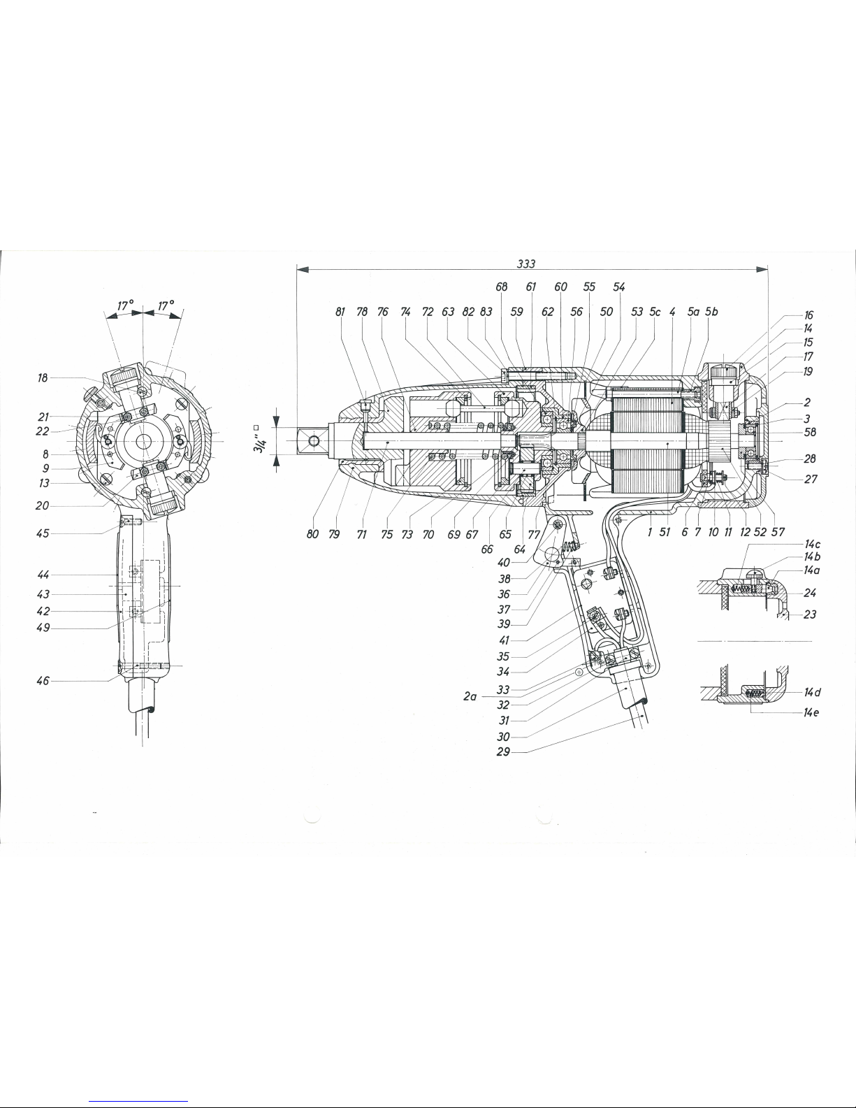
reversing ring (14) mounted on the
motor
housing.
Turn
reversing
ring
only
when
tool
is
switched
off,
otherwise commutator
and
windings
will
be
damaged.
3.
Mode
of
operation
Th
e m ot
or
dri
ves the tool
hold
er w
ith tool attac
hed via ge
arin
g,
d
rive spindl
e a
nd percussion mechanism.
The direct
dri
ve
of
a
pprox. 1,100 r.p.m. is
cut out
as soon
as the
screw
or nut has
be
en
roughly
run
down.
Once
the
motor
reaches
its rat
ed load,
the
percussion mec
hanism
comes
into
operation
and
converts
the
drive forc
e of
the
motor -which
continues
to
run
at
uniform
speed -into an
intermittent
torque applied
at
the
rat
e of 1,500
r.p
.m., i. e. two
str
okes
for
each
revolut
ion
of the dr
ive spindl
e.
Screws and
nuts are slacke
ne d
in reverse ord
er:
fir
st percussi
on
st
rokes, followed by d
irect drive. The tool is very easy to
h
andle,
as the opera
tor needs
not exert any restraining
torque.
As
the
clutch will
always
disengage as
soon
as
the rated load
is
attain
ed, the mo
tor
cannot
be overloaded.
4.
Application
The full
tightening
or
slackening
action
provided
depends
on
the time during
which the p e
rcussion
mechani
sm
is
allowed
to
run.
Max.
tig
hte
ning torque i s the s
um
of
th e to
rque ap
pli
ed by
each
stroke.
According
to
the
type
of
screwed
connection
the
max.
torque
will
generally
represent
between
80
and
150
single
torque strokes, whi
ch are
appli
ed
in 3 to 5 second
s. Availabl
e
m
ax.
torqu e
in
norm
al serv i
ce
is
185
lbs.
ft. (26
kpm)
(see dia-
gr
am
m p. 4).
Th
ere
is no point
in
applying the tool for longer th
an 5
sec
ond
s
sin
ce
th e
torq
ue will
not increase
any
furth
er, whil
e the
tool
BE 176/e BX
11.
64 Print
ed
in
German
y
i
n.
3f,,
load
lo
ad
in Watt
s
lbs
I
kg
- -
I
I I
750
1400
I
1500 I 480 280
I
11.1 5.0
I
I
I
head
will
appreciably
heat. Ove
rheating will
lead
to
increased
wear of
all
percussion
compone
nts
an d
excessive
lubri
cant con
-
s
ump
tio
n. Mor
eover,
such
overheating w
ill
make the
tool too
hot
to
handle
.
It
is not adv
isable
to u
se
attachments exceedi
ng 4.5
lbs
in
w
eigh
t, since tqe teel
holder
se
ati
ng
is
not
design
ed
for such
loads.
I
Use
U n iversa
l
Gre~se
typ
13
Sst
1
! l
ns•..,a
o r;f
o~
""r
t'/.C::
'
-·.f
,•r ,5 1
5.
Maintenance
and· lubrication
··
-
8
This w
ill
depe
nd
on the duty. The fo
llowing
ins
tru
ctio
ns
are
for conti
nuous
use
in 8-hour
day
with
actual tool
running
time
representing 20°
/o
of
total
duty
period
. The tool
hold
er (78)
should
be
lubricat
ed every ot
her
day
by mean s
of
the
oil
er
(81
)
at
the hea
d (79). U
se
machine oil
or
thin-flowing
grease
. T
he
pe
rcu
ssion mecha
nism
sho
uld
be
completely clea
ned
of
old
grea
se
at l
east
eve
ry 300 h
ours (ap
prox. 6
weeks). For this pur-
pose r
emove the
thr
ee scr
ews
(82), then
take
off
th e outer
bea
r-
ing (79) and li.f
t the percussion mechanism out of the inter
-
media
te
bearing
without
taking
it
apart.
Then
app
ly
grease
liberally to
th e
impact
fac
es of
parts (76) a
nd
(78) (30
to
40 g
or
about 1 to
P/2 oz.).
Ball pivo
ts a
nd
planetar
y
ge
arin
gs should
also
be gre
ase
d w
ith
FK
3.
FK
3 is a
high-gr
ade
quality grease and
is suitable
for a
ll
percu
ssio
n mech
anism
parts
beca
use
of
its good he
at resi
stan
ce
and adhe
rence. Ba
ll
beari
ng grea
se packin
gs shou
ld
also
be replenished with FK
3.
Should
th e
percussion mechanism
jam
or
run irregul
arly in
spite
of adequate
lubrication
and regul
ar
maint
enance
, th e
combin
ed
dri
ve
asse
mbly sho
uld
be tak
en
out
as described
und
er
par
a-
graph
7, a
nd the
individu
al parts
should
be t
ested. Frequentl
y,
ho
wev
er, uneven runni
ng
is cau
sed
by
wear
, i.e.
imp
act
dogs
which h
ave beco
me radi
use
d, or rel
axatio
n of
spring (75).
so
that sp
ring pressure
weake
ns. Worn d
ogs
can
be
regro
und.
Max.
tightening
or
slackening
torque
can
only be
obtained with
a
tool
applying
uniform strokes
along
the
axis
.
Carb
on
brushes
(17)
shoul
d b e che
cked
at
interva
ls
of abo
ut
6
w
eeks
and replaced if
appr
eci
ably wo
rn dow
n (wh en compl
e-
tely
worn dow
n th
ey will
be 7 mm
[1
/4"
]
long).
In ord
er
to re-
pl
ac
e th
em
take
off carb
on h old
er
caps (16). Replace
brushes
in
ti
me
to
avo
id
dam
age
to the commutator
.
78
21
22-~lr/1£\
'~~~
-
~
333
68
61
60 55
54
81
78
76
74
72
63 82 83 I 59 I 62 1 56 1
50
I 53 5c 4
Sa
5b
8~~-
-,-
.
($!
28
9-~.
. -
13
. "
~
27
20
45
--
--
--
--
--
14c
74b
44
U 1
~
f-'
II
/ I
'
~
\Y
..&
6.\\\n\l:'t.. \ f I
'"""
,----
14a
43
42
\Jffr ii
i/
:~
~/
/\
\\~V\\\\\
,.. '
~
23
49
46
--------
30
__/
29
~
~
:::
 Loading...