

Feig Electronic OBID i-scan ID ISC.PR101, OBID i-scan ID ISC.MR101, OBID i-scan ID ISC.PRH101 User Manual
Page 1
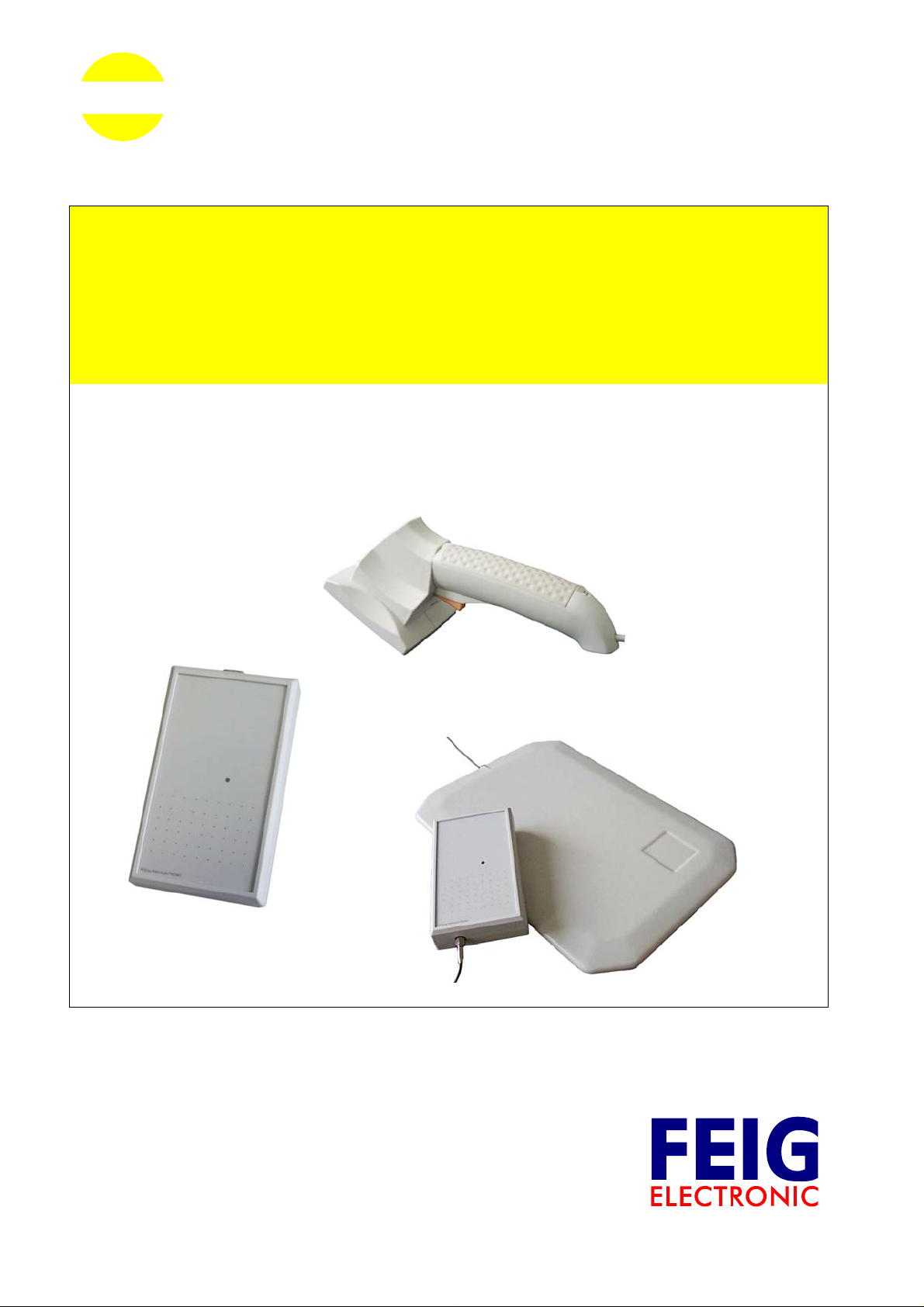
OBID i-scan
®
MANUAL
ID ISC.MR101
ID ISC.PR101
ID ISC.PRH101
Standard-Reader
Firmware-Version 1.1 and higher
ID ISC.PR101
ID ISC.PRH101
ID ISC.MR101
ID ANT340/240
final
public (B)
2006-08-10
H60301-3e-ID-B.doc
Page 2

OBID i-scan
®
System-Manual ID ISC.MR/PR/PRH101
Note
© Copyright 2002-2006 by
FEIG ELECTRONIC GmbH
Lange Strasse 4
D-35781 Weilburg-Waldhausen
Tel.: +49 6471 3109-0
http://www.feig.de
Edition: MD/06/03/30 - h60301-3e-id-b.doc
With the edition of this manual, all previous editions become void. Indications made in this manual may be changed without
previous notice.
Copying of this document, and giving it to others and the use or communication of the contents thereof are forbidden without
express authority. Offenders are liable to the payment of damages. All rights are reserved in the event of the grant of a patent
or the registration of a utility model or design.
Composition of the information in this manual has been done to the best of our knowledge. FEIG ELECTRONIC GmbH does
not guarantee the correctness and completeness of the details given in this manual and may not be held liable for damages
ensuing from incorrect or incomplete information. Since, despite all our efforts, errors may not be completely avoided, we are
always grateful for your useful tips.
The installation instructions given in this manual are based on advantageous boundary conditions. FEIG ELECTRONIC
GmbH does not give any guarantee promise for perfect function in cross environments.
FEIG ELECTRONIC GmbH assumes no responsibility for the use of any information contained in this manual and makes no
representation that they free of patent infringement. FEIG ELECTRONIC GmbH does not convey any license under its patent
rights nor the rights of others.
OBID® is registered trademark of FEIG ELECTRONIC GmbH.
OBID i-scan® is registered trademark of FEIG ELECTRONIC GmbH.
I-Code® is registered trademarks of Philips Electronics N.V.
TM
Tag-it
is a registered trademark of Texas Instruments Incorporated
General information's regarding this manual
• If bits within one byte are filled with "-", these bit spaces are reserved for future extensions or for internal
testing- and manufacturing-functions. These bit spaces must not be changed, as this may cause faulty operation of the Reader.
• The following figure formats are used:
0...9: for decimal figures
0x00...0xFF: for hexadecimal figures,
b0...1 for binary figures.
• The hexadecimal value in brackets "[ ]" indicates a control byte (command).
FEIG ELECTRONIC GmbH Page 2 of 131 H60301-3e-ID-B.doc
Page 3

OBID i-scan
Revision History of documentation...........................................................................................8
Abbreviations..............................................................................................................................9
®
System-Manual ID ISC.MR/PR/PRH101
Content
1. Data Transmission between OBID® i-scan ID ISC.MR/PR/PRH101 and Host 10
1.1. Configuration Commands and Control Commands ......................................................10
1.2. ISO15693 Host Commands .............................................................................................11
1.3. Scan-Mode........................................................................................................................14
2. Asynchronous Interface 16
2.1. Data Format and Protocol Frames ..................................................................................16
2.2. CRC16 Calculation Algorithm.........................................................................................18
3. Configuration Parameters (CFG) 19
3.1. CFG0: Reserved................................................................................................................21
3.2. CFG1: Interface .................................................................................................................21
3.3. CFG2: Inputs / Outputs general.......................................................................................25
3.4. CFG3: RF-Interface ...........................................................................................................27
3.5. CFG4: Transponder Parameters......................................................................................28
3.6. CFG5: Anticollision...........................................................................................................31
3.7. CFG6: Scan-Mode1...........................................................................................................32
3.8. CFG7: Scan-Mode2...........................................................................................................36
3.9. CFG8 + CFG9 : Selection Mask (only I-Code EPC Transponder) .................................39
3.10. CFG16: Customer Command Option Bytes..................................................................41
3.11. CFG48: Bluetooth............................................................................................................43
4. Protocols for Reader Configuration 44
4.1. [0x80] Read Configuration ...............................................................................................44
FEIG ELECTRONIC GmbH Page 3 of 131 H60301-3e-ID-B.doc
Page 4

OBID i-scan
®
System-Manual ID ISC.MR/PR/PRH101
4.2. [0x81] Write Configuration...............................................................................................45
4.3. [0x82] Save Configuration................................................................................................46
4.4. [0x83] Set Default Configuration .....................................................................................47
5. Protocols for Reader Control 48
5.1. [0x52] Baud Rate Detection..............................................................................................48
5.2. [0x55] Start Flash Loader.................................................................................................48
5.3. [0x63] CPU Reset .............................................................................................................49
5.4. [0x65] Get Software Version ............................................................................................50
5.5. [0x66] Get Reader Info......................................................................................................51
5.6. [0x69] RF Reset................................................................................................................53
5.7. [0x6A] RF ON/OFF.............................................................................................................53
5.8. [0x71] Set Output ..............................................................................................................54
5.9. [0x74] Get Input (only for ID ISC.PRH101) ......................................................................56
6. Protocols for ISO15693 Host Commands 57
6.1. [0xB0] Host commands for ISO15693 Mandatory and Optional Commands...............58
6.1.1. [0x01] Inventory........................................................................................................... 59
6.1.2. [0x02] Stay Quiet.........................................................................................................61
6.1.3. [0x22] Lock Multiple Blocks.........................................................................................62
6.1.4. [0x23] Read Multiple Blocks........................................................................................ 63
6.1.5. [0x24] Write Multiple Blocks ........................................................................................65
6.1.6. [0x25] Select................................................................................................................67
6.1.7. [0x26] Reset to Ready.................................................................................................68
6.1.8. [0x27] Write AFI...........................................................................................................69
6.1.9. [0x28] Lock AFI............................................................................................................70
6.1.10. [0x29] Write DSFI......................................................................................................71
6.1.11. [0x2A] Lock DSFI.......................................................................................................72
6.1.12. [0x2B] Get System Information.................................................................................73
6.1.13. [0x2C] Get Multiple Block Security Status.................................................................75
FEIG ELECTRONIC GmbH Page 4 of 131 H60301-3e-ID-B.doc
Page 5

OBID i-scan
®
System-Manual ID ISC.MR/PR/PRH101
6.1.14. [0xA0] Read Config Block.........................................................................................76
6.1.15. [0xA1] Write Config Block..........................................................................................77
7. Special Commands 78
7.1. [0x1B] Reset QUIET Bit (only I-Code 1 Transponders).................................................78
7.2. [0x18] Destroy (only I-Code EPC/UID Transponders)....................................................79
8. [0xB1] Host commands for ISO15693 Custom and Proprietary Commands 80
8.1. Infineon Custom Commands...........................................................................................81
8.1.1. [0x10] Read.................................................................................................................81
8.1.2. [0x30] Write .................................................................................................................82
8.1.3. [0x90] Write Byte.........................................................................................................83
8.2. KSW Custom Commands.................................................................................................84
8.2.1. [0xA0] Set Passive ......................................................................................................84
8.2.2. [0xA1] Set Log.............................................................................................................85
8.2.3. [0xA2] Get Log Status .................................................................................................86
8.2.4. [0xA3] Bist ...................................................................................................................87
8.2.5. [0xA4] Lock..................................................................................................................88
8.2.6. [0xA5] Unlock ..............................................................................................................89
8.3. Philips ISO15693 I-Code SLI Custom Commands .........................................................90
8.3.1. [0xA2] Set EAS............................................................................................................90
8.3.2. [0xA3] Reset EAS........................................................................................................90
8.3.3. [0xA4] Lock EAS..........................................................................................................91
8.3.4. [0xA5] EAS Alarm........................................................................................................92
8.4. Fujitsu ISO15693 MB89R118 Custom Commands.........................................................93
8.4.1. [0xA0] EAS Command.................................................................................................93
8.4.2. [0xA1] Write EAS.........................................................................................................93
8.5. Texas Instruments ISO15693 Tag-it™ HF-I Standard/Pro/Plus Custom Commands..95
8.5.1. [0xA4] Kill (Tag-it™ HF-I Pro)......................................................................................95
8.5.2. [0xA5] Write Single Block Pwd (Tag-it™ HF-I Pro) .....................................................95
8.6. [0xBF] ISO15693 Transparent Command .......................................................................97
FEIG ELECTRONIC GmbH Page 5 of 131 H60301-3e-ID-B.doc
Page 6

OBID i-scan
®
System-Manual ID ISC.MR/PR/PRH101
9. Supported ISO15693 Host commands 100
9.1. Supported ISO15693 Host commands for ISO15693 Transponders..........................100
9.1.1. EM4135 EM MICROELECTRONIC...........................................................................100
9.1.2. Fujitsu (MB89R116)..................................................................................................101
9.1.3. Fujitsu (MB89R118)..................................................................................................102
9.1.4. Infineon (my-d page mode) 0x60..............................................................................104
9.1.5. Infineon (ISO Address mode) 0xE0..........................................................................105
9.1.6. KSW Microtec (TempSens, VarioSens) ...................................................................106
9.1.7. Philips (I-Code SLI) .................................................................................................107
9.1.8. STMicroelectronics (LRI512)...................................................................................108
9.1.9. STMicroelectronics (LRI64)....................................................................................109
9.1.10. Texas Instruments (Tag-it™ HF-I Plus)..................................................................110
9.1.11. Texas Instruments (Tag-it™ HF-I Standard, Tag-it™ HF-I Pro) .............................112
9.2. Supported ISO15693 Host commands for I-Code 1 Transponders............................113
9.3. Supported ISO15693 Host commands for I-Code EPC Transponders.......................114
9.4. Supported ISO15693 Host commands for I-Code UID Transponders........................115
ANNEX 116
ANNEX A: Codes of Transponder Types..............................................................................116
ANNEX B: Time Behavior of the Asynchronous Interface..................................................117
ANNEX C: Time Behavior of ISO15693 Host Commands....................................................118
Time Behavior for I-Code 1 Transponders (only execution time).........................................118
Time Behavior for [0x01] Inventory and ISO15693 Transponders.......................................119
Time Behavior for common commands with independent Transponder performance.........120
ANNEX D: Index of Status Bytes ...........................................................................................121
Error-Code for ISO15693 Transponders..............................................................................123
ANNEX E: Index of Control Bytes..........................................................................................124
ANNEX F: Index of Configuration Parameters .....................................................................124
ANNEX G: Memory Model I-Code 1 Transponders ..............................................................125
ANNEX I: Examples for Read Data .......................................................................................128
FEIG ELECTRONIC GmbH Page 6 of 131 H60301-3e-ID-B.doc
Page 7

OBID i-scan
®
System-Manual ID ISC.MR/PR/PRH101
ISO15693 Host Command (DB-Size of the Transponder = 4 bytes)....................................128
ISO15693 Host Command (DB-Size of the Transponder = 8 bytes)....................................128
) Annex J: Differences between USB- and SCI-Reader.....................................................129
ANNEX K: Codes of Reader Types........................................................................................131
FEIG ELECTRONIC GmbH Page 7 of 131 H60301-3e-ID-B.doc
Page 8

OBID i-scan
®
System-Manual ID ISC.MR/PR/PRH101
Revision History of documentation
Rev. Date Page Description
0e 30.03.06
1e 26.04.06
2e 09.05.06
3e 03.06.06
49
98
First Release only for ID ISC.MR/PR/PRH101-A /-USB
and ID ISC.PRH101-B
• some corrections on page for CFG16
• added note for PRH101-B readers on page for the CPU-RESET
command
High Data Rate Return Link for ISOTransparent Commands
some corrections in the document
FEIG ELECTRONIC GmbH Page 8 of 131 H60301-3e-ID-B.doc
Page 9

OBID i-scan
®
System-Manual ID ISC.MR/PR/PRH101
Abbreviations
ADR Address
ASK Amplitude Shift Keying
CB Config Block
CFG Configuration Parameter Block
CRC Cyclic Redundancy Check
DB data block
DIP Dual Inline Plastic
FIFO First in First out
frq Frequency
FSK Frequency Shift Keying
h Hour
Hz Hertz
ID Identification
IN Input
LEN Length
LOC Location
LSB Least Significant Byte
min Minutes
ms Milliseconds
MSB Most Significant Byte
N Number
OUT Output
R/W Read / Write Access
RD Read
REL Relay
RF Radio Frequency
RSSI Received Signal Strength Indicator
RTC Real Time Clock
TAB Table
TR Transponder
TS Timeslot
UID Unique Identifier (read only Serial Number)
WO Write Only Access
WR Write
FEIG ELECTRONIC GmbH Page 9 of 131 H60301-3e-ID-B.doc
Page 10

OBID i-scan
®
System-Manual ID ISC.MR/PR/PRH101
1. Data Transmission between OBID® i-scan ID ISC.MR/PR/PRH101 and Host
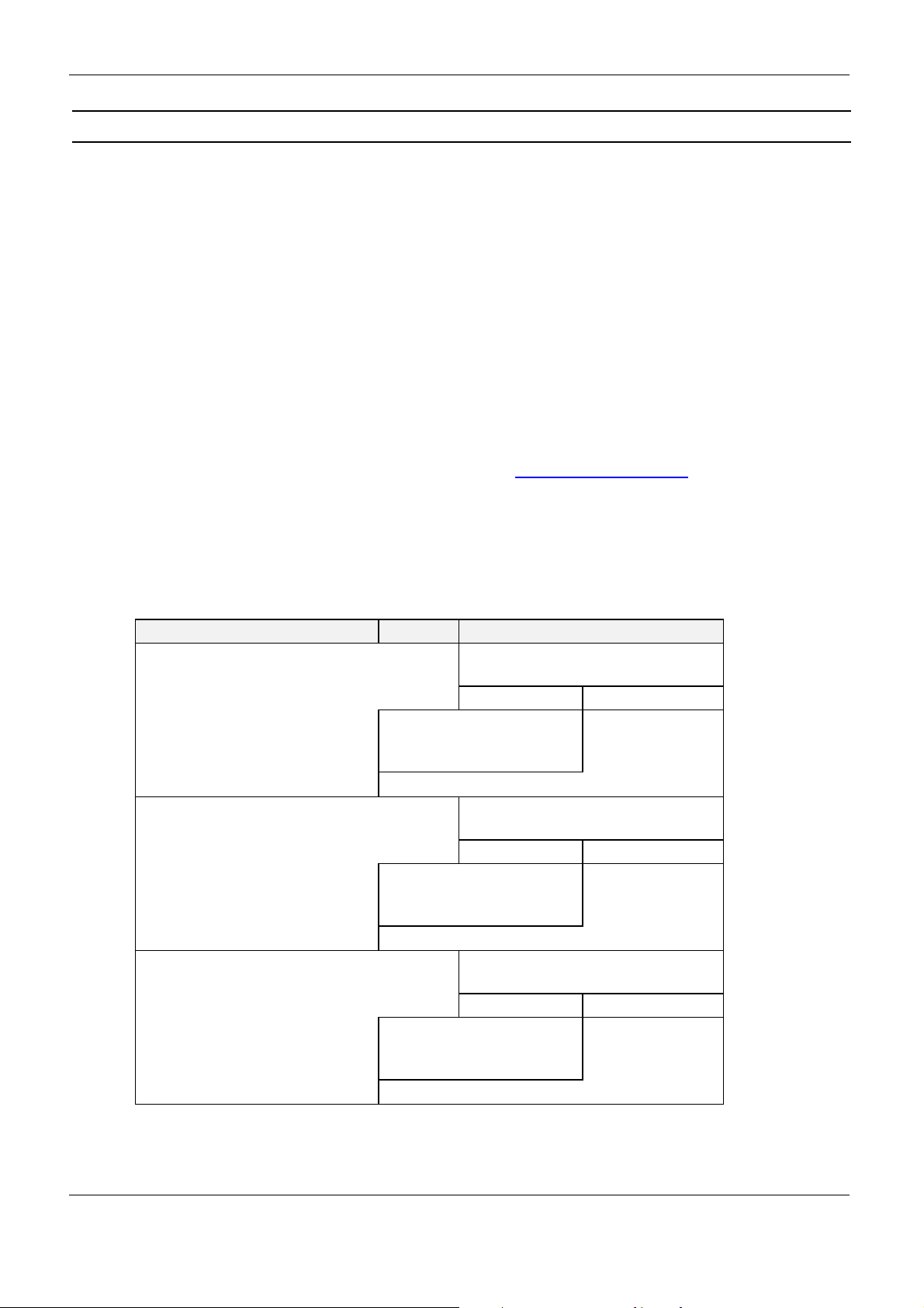
Four different ways of data transmission between OBID® i-scan Readers and host (terminal, PC) are
possible. The ISO15693Host Commands and the Scan Mode are used for the data exchange between Transponder and host, whereas the Configuration Commands and the Control serves for
adapting the Reader parameters to the individual range of applications. The following chart shows
which method of data transmission is supported by which interface:
asynchronous interface
(RS232 / RS485)
Configuration Commands
Control Commands
ISO15693Host Commands
Scan-Mode
√
√
√
√
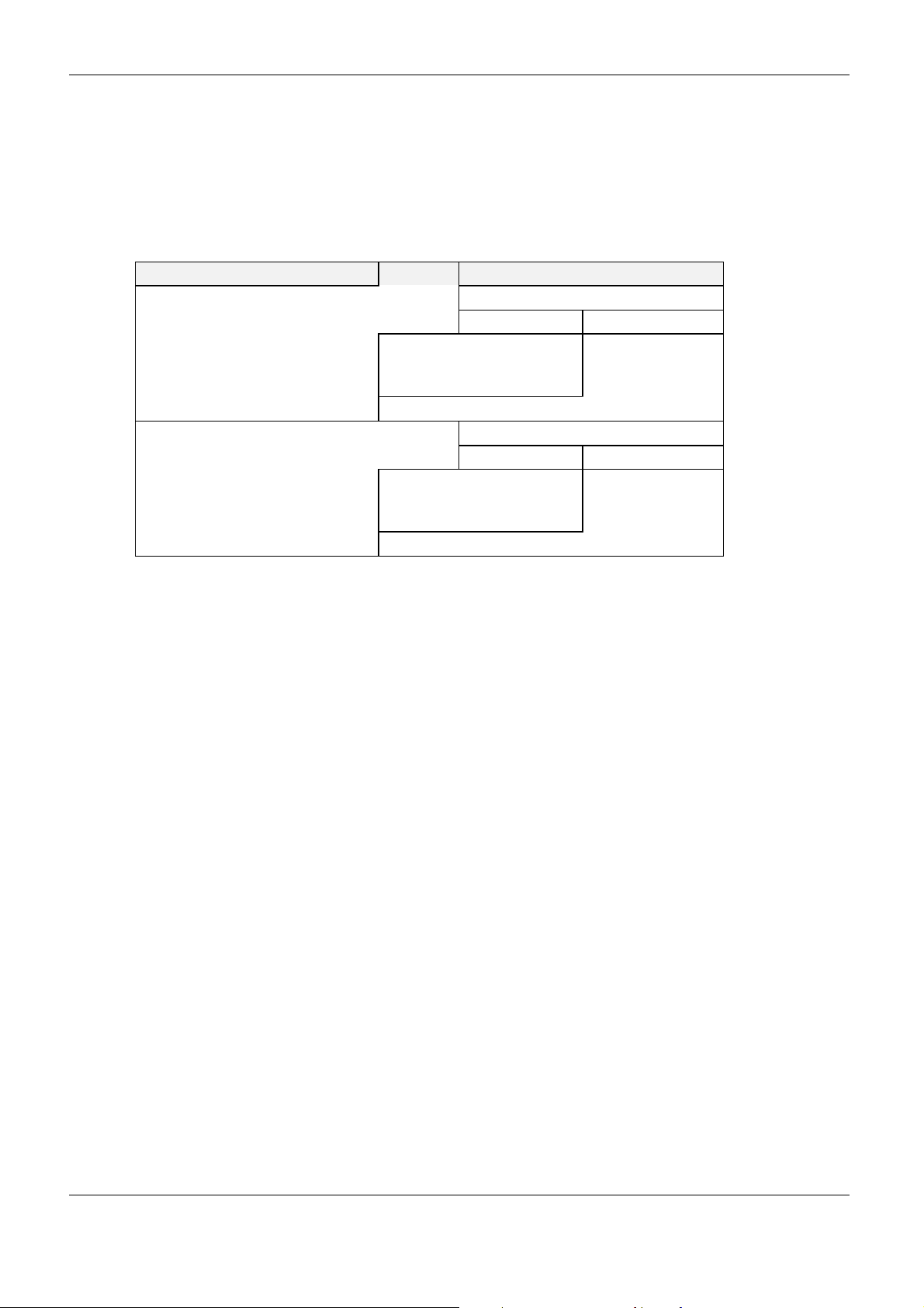
1.1. Configuration Commands and Control Commands
This method of data transmission is used for Reader configuration and the diagnosis via the asynchronous interface or USB.
The Reader-configuration parameters will be stored in the Reader memory. To store the current configuration during a power down of the Reader, the Reader-Configuration must be stored in the
EEPROM. After power up the Reader reads the configuration out of the EEPROM.
The Reader control is immediately processed and the response from the Reader contain status or
data information of the control command.
Host (Terminal / PC / ....) Reader
parameter- / control command
→
←
←
parameter received and stored / control
command processed
yes no
status /
data
error status
FEIG ELECTRONIC GmbH Page 10 of 131 H60301-3e-ID-B.doc
Page 11
OBID i-scan
®
System-Manual ID ISC.MR/PR/PRH101
1.2. ISO15693 Host Commands
The ISO Host Commands provides the exchange of data between a host and Transponders via the
Reader as long as the Transponder remains in the detection range of the Reader.
Note:
During the writing of data on a Transponder, it must be ensured that the Transponder is located within the detection range of the Reader during the entire process. If the Transponder is
removed from the detection range of the Reader during a writing process, this will cause a loss
of data.
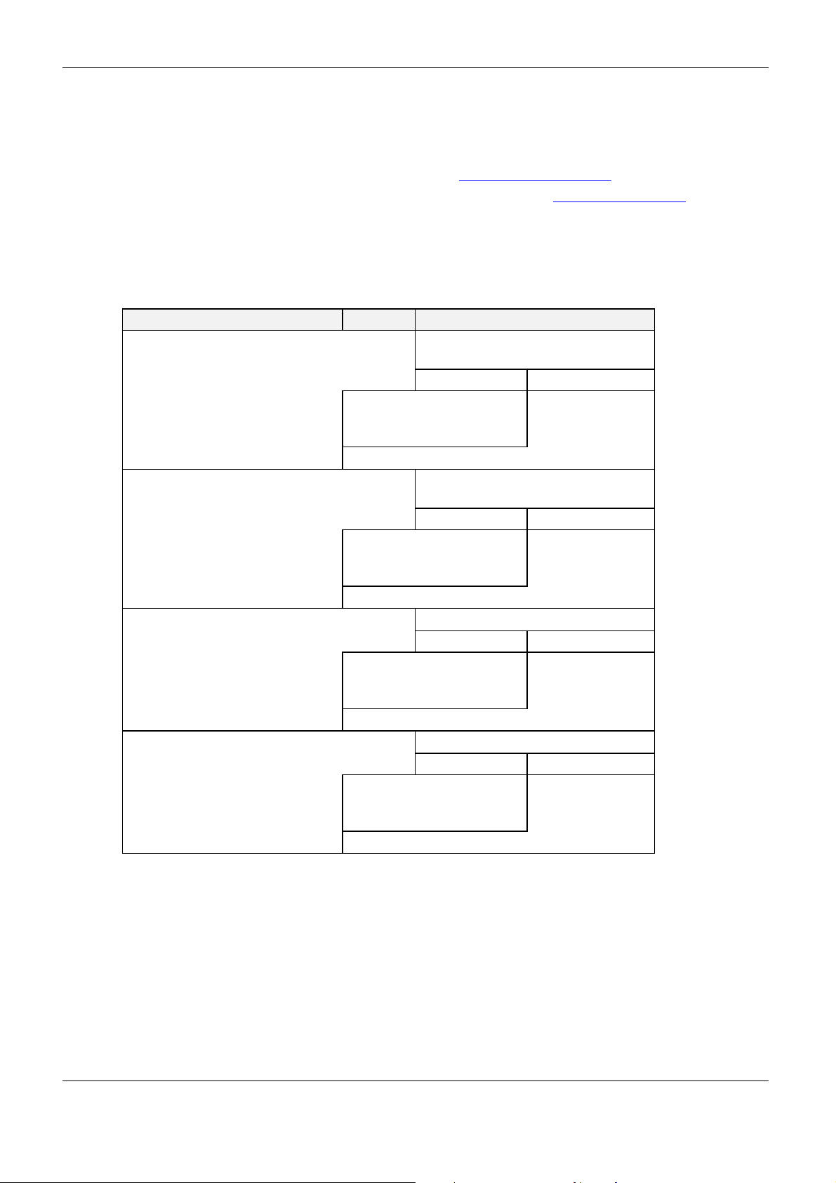
The Reader distinguishes between three different modes:
Addressed mode:
Before reading or writing data in addressed mode, the UID of the Transponder must be
known. This is executed by sending the protocol “6.1.1. [0x01] Inventory If a Transponder is
located within the detection range of the Reader at that time, it answers with its UID. For all
following read- / write orders the Transponder must be addressed with its correct UID.
The following chart will show the necessary steps for the communication with a Transponder
in addressed mode:
Host (Terminal / PC / ....) Reader
Inventory
to get the UID
read data from Transponder with UID
write data to Transponder with UID
→
←
←
→
←
←
→
←
←
Transponder in antenna field ?
Yes No
status /
number of Trans-
ponders / UID
Transponder with
correct UID in antenna field ?
Yes No
status /
Transponder read
data
Transponder with
correct UID in antenna field ?
Yes No
OK status status =
no Transponder
no Transponder
in Reader field
no Transponder
in Reader field
status =
status =
FEIG ELECTRONIC GmbH Page 11 of 131 H60301-3e-ID-B.doc
Page 12
OBID i-scan
®
Non-addressed mode:
In non-addressed mode, it is not necessary to know the UID of the Transponder. This mode is
useful, if only one Transponder is located within the range of the Reader.
The following chart will show the necessary steps for the communication with a Transponder
in non-addressed mode:
Host (Terminal / PC / ....) Reader
read data
write data
System-Manual ID ISC.MR/PR/PRH101
→
←
←
→
←
←
Transponder in antenna field ?
Yes No
status /
Transponder read
data
Transponder in antenna field ?
Yes No
OK status status = no Trans-
status = no Trans-
ponder
in Reader field
ponder
in Reader field
FEIG ELECTRONIC GmbH Page 12 of 131 H60301-3e-ID-B.doc
Page 13
OBID i-scan
Selected:
In this mode the Reader communicates only with the one, selected Transponder.
Before reading or writing data in selected mode, the UID of the Transponder must be known.
This is executed by sending at first the protocol “6.1.1. [0x01] Inventory“. In a second step the
Transponder must be selected with the select command (see: 6.1.6. [0x25] Select) which
must include its UID.
The following chart will show the necessary steps for the communication with a Transponder
in selected mode:
®
Host (Terminal / PC / ....) Reader
Inventory
to get the UID
select Transponder with UID
read data
write data
System-Manual ID ISC.MR/PR/PRH101
→
←
←
→
←
←
→
←
←
→
←
←
Transponder in antenna field ?
Yes No
status /
number of Trans-
ponders / UID
Transponder with the
correct UID in antenna field ?
Yes No
status /
Transponder read
data
selected Transponder in antenna field ?
Yes No
status /
Transponder read
data
selected Transponder in antenna field ?
Yes No
OK status status =
status =
no Transponder
status =
no Transponder
in Reader field
status =
no Transponder
in Reader field
no Transponder
in Reader field
FEIG ELECTRONIC GmbH Page 13 of 131 H60301-3e-ID-B.doc
Page 14
OBID i-scan
p
p
r
®
System-Manual ID ISC.MR/PR/PRH101
1.3. Scan-Mode
In this operation-mode the Reader autonomously sends out data to the host as soon as a Transponder is within the detection range and valid data could be read.
In Scan Mode the contents of the message block (UID, data block) can be adapted to each userapplication. Scan mode is available via the asynchronous Interface and the USB Interface.
If an USB-Reader is used in scan mode, the reader sends its data automatically over the HID interface
of the operating system. In this case, you cannot catch the data with the FEUSB.DLL or any other libraries. The reader works like a keyboard. (see also: 3.7. CFG6: Scan-Mode1).
The Reader starts the output of the protocol block as soon as all required data have been read correctly from the Transponder. If the number of transmitted user data is too large, only the maximal
number of transmitted data will be sent plus the end character.
Scan-Mode via asynchronous interface:
The data will be sent out depending on their configuration according to the following scheme,
the sequence of which cannot be changed.
Depending to the configuration and the number of Transponders in the detection range of the
Reader the transmitted protocols have a different format.
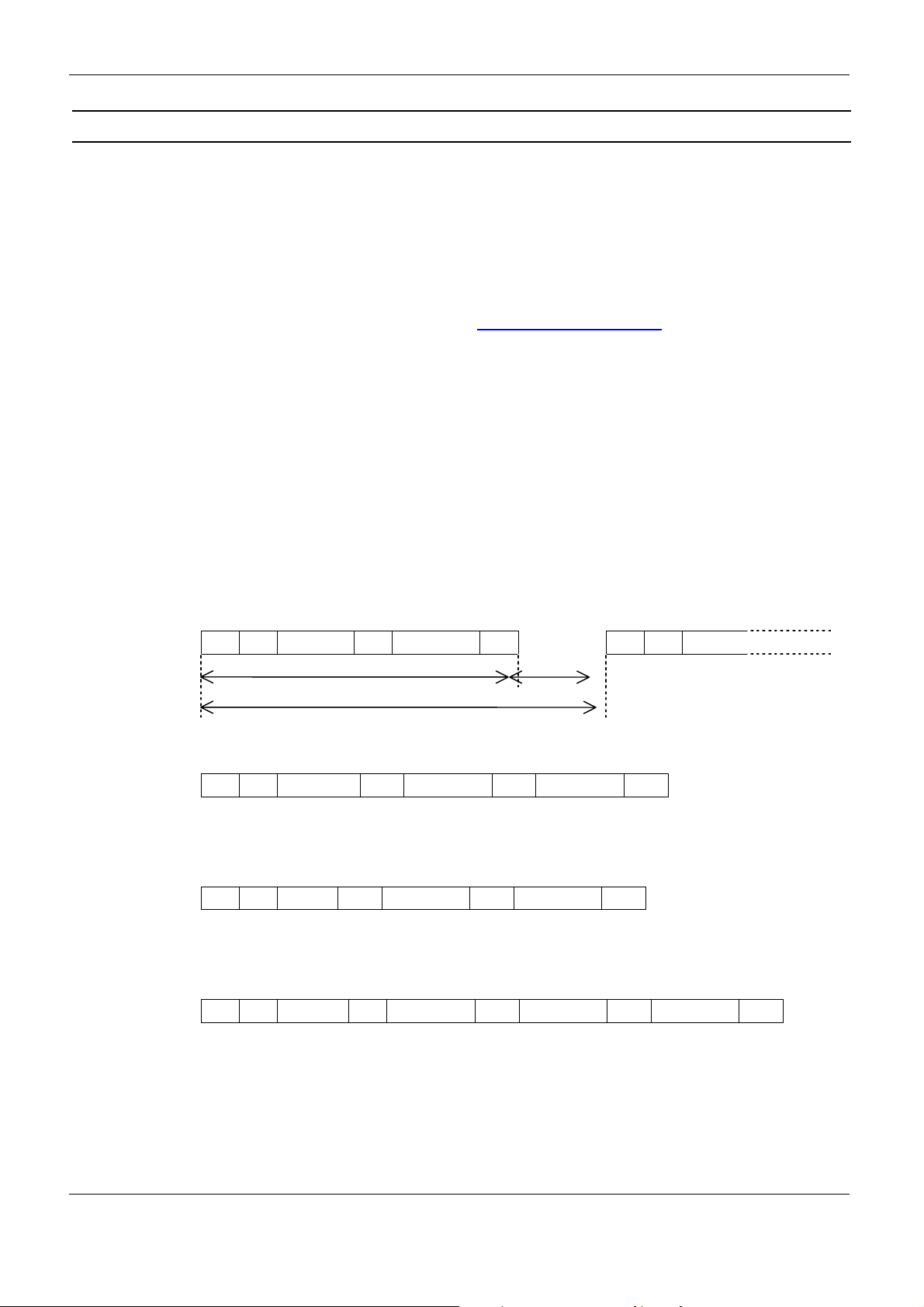
Example 1:
One Transponder in detection range and UID and data block should be read:
PR SC UID SC data EC PR SC UID
rotocol block
rotocol cycle
ts+ t
Example 2:
3 Transponder in detection range only UID should be read:
PR SC UID1 EC UID2 EC UID3 EC
Example 3:
3 Transponder in detection range only data block should be read:
PR SC data1 EC data2 EC data3 EC
Example 4:
2 Transponder in detection range UID and data block should be read:
PR SC UID1 SC data1 EC UID2 SC data2 EC
PR: Com-Prefix (optional) ts: SCAN-LOCK-TIME
UID: Serial-Number. (fix) tr: time to the next new Transponder reading
data: data blocks (free programmable)
SC Separation character (optional)
EC End character (optional)
FEIG ELECTRONIC GmbH Page 14 of 131 H60301-3e-ID-B.doc
Page 15

OBID i-scan
Example 5:
®
System-Manual ID ISC.MR/PR/PRH101
COM-
ADR
COM-
ADR
Separation
Character
SEP-CHAR USR1 USR2 USR3 USR4 UID SEP-CHAR DB USR1USR2USR
Header UID
Separation
Character
Data-
Blocks
END Character
3
(Extended Header and tail only for ID ISC.MR/PR/PRH101-A, PRH101-B from firmware version 1.3)
Scan-Mode via USB-Interface (HID-Mode):
If an USB-Reader is set to Scan-Mode the reader works like a keyboard. The data will be transferred
as USB Key Code or as hex-values.
The user defined Sep- and End- Character will be transfered as USB Key Code.
If the number of transmitted user data is too large, only the maximal number of transmitted data will be
sent plus the end character. (see: 3.7. CFG6: Scan-Mode1)
Note:
• If configuration protocols shall be sent to the Reader while the Scan-Mode is active, no
Transponder should be within the detection range of the Reader during this time.
• Only read operations are available with the Scan-Mode.
FEIG ELECTRONIC GmbH Page 15 of 131 H60301-3e-ID-B.doc
Page 16

OBID i-scan
®
System-Manual ID ISC.MR/PR/PRH101
2. Asynchronous Interface
2.1. Data Format and Protocol Frames
The Reader ID ISC.MR/PR/PRH101 can be configured by an asynchronous interface and data may be
written on Transponders or read from Transponders. The communication between Reader and connected host (terminal, PC, etc.) is executed by means of fixed protocols. The used protocol is intended
for data bus use and is equipped with a bus address.
During data transfer via the asynchronous interface the Reader supplies the required data or a status
byte. The reply contain the transmitted control byte.
There is no reply from the Reader if there is a protocol frame failure.
Protocol frame: Standard Protocol-Length (up to 255 Byte)
Host → Reader
1 2 3 4...n-2 n-1 n
LENGTH = n COM-ADR
CONTROL-
BYTE
PROTOCOL-
DATA
LSB-CRC16 MSB CRC16
Host ← Reader
1 2 3 4 (5...n-2) n-1 n
LENGTH = n COM-ADR
CONTROL-
BYTE
Protocol frame: Advanced Protocol-Length
Reader ← Host
1 2 3 4 5 (6...n-2)
STX
(0x02)
MSB
ALENGTH
LSB
ALENGTH
COM-ADR
Host ← Reader
1 2 3 4 5 6 (7...n-2)
STX
(0x02)
MSB
ALENGTH
LSB
ALENGTH
COM-ADR
STATUS
ª
(PROTOCOL-
1
CONTROL-
BYTE
n-1 n
MSB
CRC16
CONTROL-
BYTE
DATA)
(DATA)
LSB
CRC16
STATUS (DATA)
LSB-CRC16 MSB CRC16
©
©
n-1 n
1
see ANNEX D: Index of Status Bytes
ª
MSB
CRC16
LSB
CRC16
FEIG ELECTRONIC GmbH Page 16 of 131 H60301-3e-ID-B.doc
Page 17

OBID i-scan
®
System-Manual ID ISC.MR/PR/PRH101
The Reader supports both Protocol frames, standard and advanced protocol frame. The Host application can chose which protocol frame is used. If the host application chose advanced protocol frame the
Reader will always response with advanced protocol frame. If the host application chose the Standard
Protocol frame the Reader’s response will depend on the length of the response. If the host request
leads to a response with more than 255 Byte the Reader will chose the advanced protocol frame as
response frame otherwise the Reader response uses the standard protocol frame.
Information on
STX:
If the responded protocol of the Reader starts with the STX sign (0x02) the protocol
includes more than 255 Byte. Then the protocol length is defined by the 2 Byte Parameter ALENGTH.
ALENGTH (n = 8...65535):
Number of protocol bytes including STX, ALENGTH and CRC16
LENGTH (n = 6...255): Standard Protocol-Length (up to 255 Byte)
Number of protocol bytes including LENGTH and CRC16.
COM-ADR:
0..254 address of device in bus mode
Note:
The Reader can be addressed via COM-ADR 255 at any time!
CONTROL-BYTE:
Defines the command which the Reader should operate.
STATUS:
Includes the status message or protocol data from or to the Reader. The data will be
sent always as MSB first if the Reader is in the ISO15693Host Command Mode (see
also: ANNEX I: Examples for Read Data.)
DATA:
Is a optional data field with variable length. The number of DATA byte depends on
the command. The data will be sent always as MSB first if the Reader is in the Host
Command Mode.
CRC16:
Cyclic redundancy check of the protocol bytes from 1 to n-2, as specified by CCITTCRC16
16
Polynom x
+ x12 + x5 + 1
Start Value 0xFFFF
Data format:
FEIG ELECTRONIC GmbH Page 17 of 131 H60301-3e-ID-B.doc
Page 18

OBID i-scan
®
Start bits: 1
Data bits: 8
Stop bits: 1
Parity: even (default)
Timing conditions:
Starting delay:
Before sending a starting sign (length byte) of a protocol, there must be a delay of
minimum 5 ms.
Host → Reader:
Host ← Reader:
Data timeout:
Within one protocol, the characters have to follow each other in intervals of maximum 12 ms.
Host → Reader:
System-Manual ID ISC.MR/PR/PRH101
odd
none
..
Reaction time Starting delay .. ..
Õ 5...n ms ÖÕ min. 5 ms Ö
.. .. ..
Õ max. 12 ms ÖÕ max. 12 ms ÖÕ max. 12 ms Ö
Char n Char n+1 Char n+2 ..
2.2. CRC16 Calculation Algorithm
Polynom: x16 + x12 + x5 + 1 ⇒ CRC_POLYNOM = 0x8408;
Start Value: 0xFFFF ⇒ CRC_PRESET = 0xFFFF;
C-Example:
unsigned int crc = CRC_PRESET;
for (i = 0; i < cnt; i++) /* cnt = number of protocol bytes without CRC */
{
crc ^= DATA[i];
for (j = 0; j < 8; j++)
{
if (crc & 0x0001)
crc = (crc >> 1) ^ CRC_POLYNOM;
else
crc = (crc >> 1);
}
}
FEIG ELECTRONIC GmbH Page 18 of 131 H60301-3e-ID-B.doc
Page 19

OBID i-scan
3. Configuration Parameters (CFG)
®
System-Manual ID ISC.MR/PR/PRH101
The configuration memory of the Reader is organized in configuration blocks of 16 byte each. These
are divided into 14-byte configuration parameters and a 2-byte CRC16 checksum. Each of these configuration blocks takes a number (CFG 0...CFG n).
Structure of a configuration block in Reader configuration memory and Reader EEPROM (CFG):
Byte 0 1 2 3 4 5 6 7 8 9 10 11 12 13 14 15
Contents PARAMETER CRC16
The parameters are stored in two different configuration memory locations:
• Reader RAM
• Backup EEPROM (used for storing parameter after power down)
Multiple configuration memory locations can be addressed by the value of the parameter CFG-ADR
used in chapter 4. Protocols for Reader Configuration
CFG-ADR:
CFGn: memory-address of the required configuration block
LOC: specifies the location of the configuration block (RAM / EEPROM)
MODE: specifies one or all configuration blocks
Bit: 7 6 5 4 3 2 1 0
Function LOC MODE CFGn: address of configuration block
The EEPROM configuration blocks are protected by a 16 bit CRC-checksum. The examination of
these checksums is executed after each reset of the Reader. If a checksum error is found, the Reader
goes into an error status "EE-Init-Mode" and sets the configuration block which is faulty to the default
values.
While the EE-Init-Mode is active, the LED blinks alternately red and green and the Reader answers
external commands with the status "0x10 EEPROM Failure". The "EE-Init-Mode" can be exited now by
a new reset (cold start or 5.3. [0x63] CPU Reset command). If after this the checksums of all data
records are correct, the Reader shifts to the configured operation mode.
Notes:
• Malfunctions may occur if parameters are configured outside their described range or if
unspecified parameters have been changed!
• A firmware update resets the EEPROM to default settings and the Reader goes into the er-
ror status “EE-Init-mode”.
FEIG ELECTRONIC GmbH Page 19 of 131 H60301-3e-ID-B.doc
Page 20

OBID i-scan
r
f
r
®
System-Manual ID ISC.MR/PR/PRH101
Structure of configuration parameter description.
Byte 0 1 2 ......n
contents RAM-eff. EEPROM-
eff.
00
res
.....
not marked
Changing of this parameter becomes immediately
effective after writing /
saving this configuration
block to RAM
gray marked
Changing of this parameter only becomes effective
after writing / saving this
configuration block to
EEPROM and a Reade
reset
marked with “00“
these bits or bytes are reserved fo
future extensions or for internal
testing and manufacturingfunctions. These bits or bytes and
also any not described bits and
bytes must not be changed, as
this may cause faulty operation o
FEIG ELECTRONIC GmbH Page 20 of 131 H60301-3e-ID-B.doc
Page 21

OBID i-scan
®
System-Manual ID ISC.MR/PR/PRH101
3.1. CFG0: Reserved
The configuration block CFG0 is reserved for future use.
Byte 0 1 2 3 4 5 6
Contents 0x00 0x00 0x00 0x00 0x00 0x00 0x00
Default
Byte 7 8 9 10 11 12 13
Contents 0x00 0x00 0x00 0x00 0x00 0x00 0x00
Default
3.2. CFG1: Interface
The parameters of the CFG1 configuration block contain the data communication settings.
Byte 0 1 2 3 4 5 6
Contents COM-ADR 0x00
Default 0x00 0x08 0x01 0x00 0x00
0x00 38400 Baud e,8,1
USB-Ver-
sion
0x00 0x00 0x00 0x00 0x00
Byte 7 8 9 10 11 12 13
Contents TR-
RESPONSE-
TIME
0x00 0x00 0x00 0x00 INTERFACE READER -
Default 0x1E 0x01 MR/PR: 0x00
3 sec.
USB-Ver-
sion
0x1E 0x00
BAUD
1
TRANS-
FORM
1
ADVANCED
MODE
0x00 TR-
RESPONSE-
TIME
MODE
PRH: 0x01
COM-ADR:
Bus address of the Reader (0 .. 254) for communication via the asynchronous interface, especially for applications with the RS485 interface.
Notes:
• Do not configure address 255!
FEIG ELECTRONIC GmbH Page 21 of 131 H60301-3e-ID-B.doc
Page 22

OBID i-scan
• Via the COM-Adr 255 in the send protocol, the Reader is able to be addressed at any
time. It answers then with the configured address.
• Not available by the USB-Reader
1
BAUD
:
By means of this byte the baud rate of the asynchronous interface can be defined.
5: 4800 baud
6: 9600 baud
7: 19200 baud
8: 38400 baud
Note:
• Changing of BAUD only becomes effective after writing / saving configuration block
• The Reader set the baud rate to 38400 baud, if the user set an invalid baudrate.
®
System-Manual ID ISC.MR/PR/PRH101
CFG1 to EEPROM and a reset of the Reader.
• Not available by the USB-Reader
TRANS-FORM
By means of this byte, several parameters for the data transmission format of the asynchronous interface can be defined.
Bit: 7 6 5 4 3 2 1 0
Function: 0 0 0 0 S D P
P: Kind of Parity
D: Number of Data Bits
S: Number of Stop Bits
2
:
b00: no Parity
b01: even Parity
b10: odd Parity
b11: - do not use -
b0: 8 Data Bits
b1: - do not use -
b0: 1 Stop Bit
b1: - do not use -
1
A plausibility check is performed by writing this parameter to the Reader. If an error occurs the Reader an-
swers with STATUS = 0x11.
2
A plausibility check is performed by writing this parameter to the Reader. If an error occurs the Reader an-
swers with STATUS = 0x11.
FEIG ELECTRONIC GmbH Page 22 of 131 H60301-3e-ID-B.doc
Page 23

OBID i-scan
®
Note:
• Changing of TRANS-FORM only becomes effective after writing / saving configura-
tion block CFG1 to EEPROM and reset of the Reader.
• Always 8 Data Bits and 1 Stop Bits should be used
• Not available by the USB-Reader
ADVANCED MODE:
Bit: 7 6 5 4 3 2 1 0
Function: 0 0 0 0 0 0 0
By setting this bit the Reader behaves like MR/PR/PRH100. On a request in normal mode the
readers response is also in normal mode.
Bit0:
System-Manual ID ISC.MR/PR/PRH101
Bit0
b0: reader automatically answers in advanced mode, if data length is longer
than 255 Byte.
b1: reader always answers in normal mode. If there is data length longer than
255 Byte the reader sets MORE Byte.
TR-RESPONSE-TIME:
By means of this parameter the maximum duration for the Transponder command can be defined.
The TR-RESPONSE-TIME starts after the Reader has received a new command. At the latest after the TR-RESPONSE-TIME elapsed the Reader will send an answer protocol. In this
case, the current commands between Reader and Transponder are aborted. If this time is too
short the Interface Status “0x83 RF Communication Error“ will appear.
TR-RESPONSE-TIME 0...65535 * 100 ms
Note:
• TR-RESPONSE-TIME has no effect with the protocols for Reader Configuration and
the protocols for Reader Control.
max. response duration
• The TR-RESPONSE Time must be < “Block Timeout” in the Host COM-Port settings.
FEIG ELECTRONIC GmbH Page 23 of 131 H60301-3e-ID-B.doc
Page 24

OBID i-scan
®
System-Manual ID ISC.MR/PR/PRH101
INTERFACE:
By means of this byte, the Reader Interface can be defined (RS232 or RS485)
Bit: 7 6 5 4 3 2 1 0
Function: 0 0 0 0 0 0
Default: 0 0 0 0 0 0 0
READER-MODE:
By means of this byte, the Reader mode can be defined.
Bit: 7 6 5 4 3 2 1 0
Function: 0 0 0 0 0 0 0 SCAN-E
SCAN-E:
RS485 RS232
By setting this bit the Scan-Mode can be enabled
b0: ISO15693Host Mode
(see chapter 6. Protocols for ISO15693 Host Commands)
b1: Scan-Mode (see chapter 3.7. CFG6: Scan-Mode1)
1
.
1
1
only for ID ISC.MR/PR101-A
FEIG ELECTRONIC GmbH Page 24 of 131 H60301-3e-ID-B.doc
Page 25

OBID i-scan
®
System-Manual ID ISC.MR/PR/PRH101
3.3. CFG2: Inputs / Outputs general
Via the following parameters the operation mode of the LED and the buzzer (only ID ISC.PRH101) can
be configured at any time. One byte each is reserved for the active and mute position, by means of
which the individual operation modes according to the schedule below may be adjusted. In addition to
this, for the active- and mute position different flashing frequencies of the LED and intervals of the
buzzer may be defined. So, the LED may be used as an operation indicator.
Byte 0 1 2 3 4 5 6
Contents 0x00 0x00 0x00 IDLE-STATE IDLE-FLASH 0x00 0x00
Default 0xA9 0x00
Byte 7 8 9 10 11 12 13
Contents ACTIV-
Default MR/PR: 0x26
STATE
PRH: 0x96
ACTIV-
FLASH
0x00 0x0A 0x0A MR/PR: 0x00
ACTIV-
GRN-TIME
ACTIV-
RED-TIME
ACTIV-
BUZZER-
TIME
PRH: 0x05
0x00 0x00
1 sec. 1 sec. 1 sec.
USB-Version
MR/PR: 0x26
PRH: 0x96
MR/PR: 0x00
PRH: 0x05
Note:
• The Readers dispose of a two colored LED (red / green). The color orange can be obtained
by combining both basic colors red and green.
Colors ID ISCMR / PR:
LED
Color:
red 1 0
green 0 1
orange 1 1
red green
• The buzzer is only with the ID ISC.PRH101 available.
IDLE-STATE / ACTIVE-STATE
One byte each for idle- and tag-detect state is used to set the operation mode of the signal
transmitter.
Bit: 7 6 5 4 3 2 1 0
Function: Startup
Buzzer/
LED
0 BUZZER RED
(PRH: BLUE)
GRN
FEIG ELECTRONIC GmbH Page 25 of 131 H60301-3e-ID-B.doc
Page 26

OBID i-scan
®
System-Manual ID ISC.MR/PR/PRH101
GRN / RED / BUZZER (PRH: BLUE instead of RED)
Bit Combination Signal device
b00 unchanged
b01 on
b10 off
b11 flashing
Startup Buzzer / LED (only idle state)
When this option is selected, the Reader will switch the BUZZER and the LEDs on
for two seconds to indicate that the Reader is ready after the Reader is supplied with
power. If the Reader is reset by software, only both LEDs switch on for 2 seconds.
IDLE-FLASH / ACTIV-FLASH:
By means of the two bytes "IDLE-FLASH" and "ACTIV-FLASH" the signal transmitter may be provided with a flashing frequency for idle and active position.
Bit: 7 6 5 4 3 2 1 0
Function: 0 0 BUZZER RED GRN
Bit combination flashing frequency
b11
b10
b01
b00
1 Hz
2 Hz
4 Hz
8 Hz
ACTIV-xxx-TIME
If a Transponder was detected, the transmitter and the duration can be set by the bytes ACTIV-STATE
and ACTIV-FLASH. Each signal transmitter (LED, BUZZER) may be activated temporarily limited.
Signal transmitter
ACTIV-GRN-TIME
ACTIV-RED-TIME
ACTIV-BUZZER-TIME
time range
0...255 x 100 ms
0...255 x 100 ms
0...255 x 100 ms
FEIG ELECTRONIC GmbH Page 26 of 131 H60301-3e-ID-B.doc
Page 27

OBID i-scan
®
System-Manual ID ISC.MR/PR/PRH101
3.4. CFG3: RF-Interface
The parameters of the CFG3 configuration block contain general Transponder driver and Reader settings.
Byte 0 1 2 3 4 5 6
Contents
Default /
101-Series
Byte 7 8 9 10 11 12 13
Contents 0x00 0x00 0x00 0x00 0x00 0x00 0x00
Default
TAG-DRV
0x0009
TAG-DRV1:
Defines the Transponder types that are operated by the Reader.
Byte: 0 1
Bit: 15 14 13 12 11 10 9 8 7 6 5 4 3 2 1 0
Driver 0 0 0 0 0 0 0 0 .H .G 0 0 .D 0 0 .A
1
0x00 0x00 0x00 0x00 0x00
b0: Driver for the Transponder type is inactive
b1: Driver for the Transponder type is active
.A: Driver for I-Code 1
.D: Driver for ISO15693
.G: Driver for I-Code EPC (must be released first)
.H: Driver for I-Code UID (must be released first)
On principle, only those Transponder drivers should be active that are used in the
actual application. Thus, the reaction time of the Reader for Transponder read- /
write-operations is reduced and the danger of a parasitic Transponder access is
minimized.
Note:
The I-Code EPC and UID Firmware must be released with the command “Set
Firmware Upgrade” first. For this you have to use the demo program ID
ISOStart and the Upgrade Code must be ordered by Feig Electronic.
1
A plausibility check is performed by writing this parameter to the Reader. If an error occurs the Reader an-
swers with STATUS = 0x11.
FEIG ELECTRONIC GmbH Page 27 of 131 H60301-3e-ID-B.doc
Page 28

OBID i-scan
®
System-Manual ID ISC.MR/PR/PRH101
3.5. CFG4: Transponder Parameters
The parameters of the CFG4 configuration block contain general Transponder settings.
Byte 0 1 2 3 4 5 6
Contents I-Code-
MODE
Default 0x00 0x00 0x00 0x0B 0x00 0x00
Byte 7 8 9 10 11 12 13
Contents CUSTOMER
OPTION
Default 0x00 0x04
I-Code-MODE: (only I-Code Transponder)
Bit: 7 6 5 4 3 2 1 0
Function Mapping 0 0 0 0 0 0 0
FAM-CODE APP-ID 0x00 ISO 15693
MODE
0x00 0x00 0x00 0x00 0x00 ISO-Block-
ISO 15693
AFI
ISO 15693
OPTION
size
Mapping:
b0: FEIG Memory Model (default)
b1: Original I-Code Memory Model
Note:
• If Mapping is set to “original I-Code Memory Model” the ISO15693 Host Command
Read Config Block[0xA0] and Write Config Block [0xA1] will not be available.
To change the Config Block 0,1,2 can now be done with Write Multiple Blocks [0x24]
on the original I-Code Address 2,3,4.
FAM-CODE: (only I-Code 1 Transponders)
Family Code to select a Transponder
APP-ID: (only I-Code 1 Transponders)
Application ID to select a Transponder
Note:
If FAM-CODE and APP-ID are zero, all I-Code 1 Transponders will response. Otherwise only the
Transponders with matching FAM-CODE and APP-ID will respond.
FEIG ELECTRONIC GmbH Page 28 of 131 H60301-3e-ID-B.doc
Page 29

OBID i-scan
®
ISO 15693 MODE:
Bit: 7 6 5 4 3 2 1 0
Function 0 0 AFI NO-TS DATA-
DATACODING
MOD
SUB-CARRIER
DATA-RATE
System-Manual ID ISC.MR/PR/PRH101
b0: - do note use -
b1: Fast Mode (1 / 4)
b0: - do note use –
b1: 10%
b0: ASK (one sub-carrier)
b1: - do note use -
b0: - do note use -
b1: high
RATE
SUB-
CARRIER
MOD DATA
CODING
NO-TS
b0: 16 timeslots
b1: 1 timeslot
Note:
Anticollision is only possible if NO-TS=16.
AFI
b0: disabled
b1: enabled
ISO 15693 AFI:
Application Family Identifier to select a Transponder
ISO 15693 OPTION:
Bit: 7 6 5 4 3 2 1 0
Function 0 0 0 0 WR-OPTION 0 0
WR-OPTION:
b00: automatically set
b10: Tag Option = 0
b11: Tag Option = 1
Note:
• If WR-OPTION is automatically set, the Reader sets the WR-OPTION to 0, if the
ISO15693Host Command is in non-addressed mode. In the case of a Tag-it HF-I Standard/Plus/Pro the WR-OPTION must be set to 1 for all Write and Lock commands to
respond properly.
• See chapter 9.1. Supported ISO15693 Host commands for ISO15693 Transponders for more
details about the correct WR-OPTION.
FEIG ELECTRONIC GmbH Page 29 of 131 H60301-3e-ID-B.doc
Page 30

OBID i-scan
®
System-Manual ID ISC.MR/PR/PRH101
CUSTOMER OPTION (from firmware version 1.04-A, 1.03-USB):
Bit: 7 6 5 4 3 2 1 0
Function 0 0 0 0 0 0 0
Bit0 (INFINEON-OPTION):
b0: Use ISO Cmd’s for Read/Write Infineon-Tag (4Byte Blocksize)
b1: Use Infineon Custom Cmd’s for Read/Write Infineon-Tag (8Byte Blocksize)
ISO-Blocksize:
Defines the block size of an unknown ISO-transponder or if the transponder is used in the
non-addressed mode.
Range: 0x01 ... 0xFF
A value of 0x00 will be automatically set to a block size of 4byte.
Bit0
FEIG ELECTRONIC GmbH Page 30 of 131 H60301-3e-ID-B.doc
Page 31

OBID i-scan
®
System-Manual ID ISC.MR/PR/PRH101
3.6. CFG5: Anticollision
The parameters of the CFG5 configuration block contain anticollision settings.
Byte 0 1 2 3 4 5 6
Contents
Default 0x02
Byte 7 8 9 10 11 12 13
Contents 0x00 0x00 0x00 0x00 ONT 0x00 0x00
Default 0x01
TIMESLOTS
TIMESLOTS: (only I-Code 1 and I-Code EPC/UID Transponders)
Number of timeslots with which Transponders will be read.
TIMESLOTS Number of Timeslots ID ISC.MR/PR/PRH101
0x03
0x02
0x01
0x00
1
0x00 0x00 0x00 0x00 0x00 0x00
16
8
4
1
√
√
√
√
• Each I-Code 1 and I-Code EPC/UID Transponder responds in a chosen timeslot. Choosing
too much timeslots compared to the number of Transponders in the antenna field causes
that only a small number of Transponders can be selected at one time. On the other hand
are too many timeslots very time consuming. The optimum number of timeslots is about
twice the number of Transponders expected in the antenna field at the same time.
ONT:
Defines which Transponder will send to the host.
Bit: 7 6 5 4 3 2 1 0
Driver 0 0 0 0 0 0 0 ONT
ONT:
b0: all Transponders in the field will be send to the host. The Reader performs a
RF Reset before any command reads a UID
b1: only the new selected Transponders will sent to the host
Note:
If 1 timeslot is set and the CRC on an I-Code EPC is wrong the serial number will be transferred
and the status is set to “[0x02] Data False”
1
A plausibility check is performed by writing this parameter to the Reader. If an error occurs the Reader an-
swers with STATUS = 0x11.
FEIG ELECTRONIC GmbH Page 31 of 131 H60301-3e-ID-B.doc
Page 32

OBID i-scan
®
System-Manual ID ISC.MR/PR/PRH101
3.7. CFG6: Scan-Mode1
The parameters of the CFG6 configuration block contain Scan-Mode settings. To enable Scan-Mode
the SCAN-MODE bit in the configuration block CFG1 (3.2. CFG1: Interface) must be set.
Byte 0 1 2 3 4 5 6
Contents SCANNER-
MODE
Default
MR101
Default
PRH101
Byte 7 8 9 10 11 12 13
Contents SCAN-LOCK-
Default
MR101
Default
PRH101
0x02 0x01 0x00
0x80 0x01 0x00
TIME
0x0A
1 sec.
0x0A
1 sec.
0x00 0x00 SCAN-DATA 0x00 0x00 SCAN-LOCK-
TIME
0x00 0x00 0x00 DB-ADR D-LGT D-START
0x05 0x04 0x00
0x05 0x04 0x00
SCANNER-MODE
defines the mode of the scanner.
Bit: 7 6 5 4 3 2 1 0
Function Trigger 0 0 0 0 mode
mode:
Trigger:
b000: Single Read: (active for read duration – stops after good read)
When all Transponders in detection range has been decoded, the Reader
will stop the scan. The Reader must be triggered again to read other Transponders.
b010: Continuos Read:
The Reader will read as much Transponders as it can decode regardless
whether it is the same or not. This mode is mainly used for demonstration
and diagnostic.
b0: Trigger disabled:
The Reader scans all the time. However, this mode increase the current
consumption
b1: Trigger enabled: (only ID ISCPRH101)
The Reader start the scan, if the trigger is activated by the external switch.
Note
If Trigger is enabled an not activated by the external switch, the RFfield will be switched off.
FEIG ELECTRONIC GmbH Page 32 of 131 H60301-3e-ID-B.doc
Page 33

OBID i-scan
SCAN-DATA
selects the data types to be send in the Scan Mode.
Function Byte
Notes:
• If the bits UID and DB are set to 0, the scan-mode is switched off.
UID = Serial No.
DB = Data Block
®
Bit: 7 6 5 4 3 2 1 0
COM-
Order
Prefix
System-Manual ID ISC.MR/PR/PRH101
0 0 0 0 DB UID
Setting of this bit activates the output of the UID
b0 Output of the UID inactive
b1 Output of the UID active
Setting of this bit activates the output of a specified data field.
b0 Output of a data field inactive
b1 Output of a data field active
COM Prefix
When this option is on, the Reader will transmit the COM-ADR before each data set.
b0 COM-ADR of the Reader will not transmit
b1 COM-ADR of the Reader will transmit
Byte Order
Defines the Byte Order within frame
b0 MSB first
b1 LSB first
Note:
If the COM Prefix is enabled the COM-ADR will be send in front of the Header
FEIG ELECTRONIC GmbH Page 33 of 131 H60301-3e-ID-B.doc
Page 34

OBID i-scan
r
r
®
System-Manual ID ISC.MR/PR/PRH101
SCAN-LOCK-TIME: (1 ... 65535 * 100 ms = 100 ms ... 6553,5 sec)
The SCAN-LOCK-TIME defines the period in which the Reader does not transmit the Transponder data a second time, after it has transmitted it the first time. (regardless whether the
Transponder is in the detection range of the reader during SCAN-LOCK-TIME or not). The
SCAN-LOCK-TIME starts after the data transmission from the Transponder to the Reader.
start of read
Transponder in field
SCAN-LOCK-TIME
Data output
t
t
o
t
s
tr: Time to read the Transponder data
t
t
o
t
s
DB-ADR:
D-LGT:
: Data Transmission from the Reader to the host
t
o
: SCAN-LOCK-TIME
t
s
As long as the SCAN-LOCK-TIME is active, the Transponder can be in the detection
range of the reader or outside of it.
Transponder address of the first data block which will be transferred in Scan-Mode.
Range: 0x00...0xFF.
See for valid addresses: ANNEX G: Memory Model I-Code 1 Transponders and 9.1. Suppo
ted ISO15693 Host commands for ISO15693 Transponders
D-LGT defines the length of raw data which are transmitted in the Scan-Mode.
Number of data bytes to be transferred, starting with the D-START.
Example:
data block
Byte 0 1 2 3 4 5 6 7
Data 0x01 0x23 0x45 0x67 0x89 0xAB 0xCD 0xEF
r-
D-START = 1
D-LGT = 4
Output Data 0x23 0x45 0x67 0x89
FEIG ELECTRONIC GmbH Page 34 of 131 H60301-3e-ID-B.doc
Page 35

OBID i-scan
®
System-Manual ID ISC.MR/PR/PRH101
D-START:
This parameter defines the first byte in the raw data (defined by DB-ADR and D-LGT), which
will be transferred in Scan-Mode. To transfer the whole data block D-START must be set to 0.
Note:
The size of one data block depends on the type of Transponder.
The maximum number of the transferred data bytes depends on the reader type and configuration
settings and the used sign type.
hex-formatted ASCII formatted
RS232/
without serial
number
128 signs 128 signs 128 signs 80 signs 72 signs 71 signs
with serial
number
with 1 separation
character
without serial
number
with serial
number
with 1 separation
character
485
40 signs
32 signs
32 signs
80 signs
64 signs
63 signs
USB
40 special char.
* Only characters from A to X and 0 to 9 are non special character.
32 special char.
32 special char.
53 special char.
43 special char.
42 special char.
Note:
If an USB-Reader is used in Scan mode and “ASCII formatted hex-data” is configured it will be
distinguish between letters, numbers and special character(symbols). The special characters
will be first changed into the Unicode than into the USB-Keycode. Therefore you can transfer
more letters and numbers than special characters.
FEIG ELECTRONIC GmbH Page 35 of 131 H60301-3e-ID-B.doc
Page 36

OBID i-scan
®
System-Manual ID ISC.MR/PR/PRH101
3.8. CFG7: Scan-Mode2
Byte 0 1 2 3 4 5 6
Contents DB-USE SEP-CHAR SEP-USER END-CHAR END-USR1 END-USR2 END-USR3
Default 0x02 0x20 0x2C 0x01 0x00 0x00 0x00
Byte 7 8 9 10 11 12 13
Contents
Default 0x00 0x00 0x00 0x00 0x00
0x00
DB-USE:
Defines the data format of the data and the value of the data.
Bit: 7 6 5 4 3 2 1 0
Function 0 0 0 0 DB-FORMAT
HEADER-
USR1
HEADER -
USR2
HEADER -
USR3
HEADER -
USR4
0x00 LEN-USR
DB-FORMAT
b0000 unformatted hex-data
b0010 ASCII formatted hex-data
In this case the data are transferred as they were read by the reader
In this case the raw data from the Transponder were converted to ASCII Code before transfer. For this purpose, the data bytes first are separated
into their Nibbles and then changed into ASCII signs according the following
table.
raw data
(hex / binary)
0x0 b0000 '0' 0x30
0x1 b0001 '1' 0x31
0x2 b0010 '2' 0x32
0x3 b0011 '3' 0x33
0x4 b0100 '4' 0x34
0x5 b0101 '5' 0x35
0x6 b0110 '6' 0x36
0x7 b0111 '7' 0x37
0x8 b1000 '8' 0x38
0x9 b1001 '9' 0x39
0xA b1010 'A' 0x41
0xB b1011 'B' 0x42
0xC b1100 'C' 0x43
0xD b1101 'D' 0x44
0xE b1110 'E' 0x45
0xF b1111 'F' 0x46
ASCII data
(ASCII / hex)
FEIG ELECTRONIC GmbH Page 36 of 131 H60301-3e-ID-B.doc
Page 37

OBID i-scan
SEP-CHAR:
Selects the separation character between two data types for the send data.
Function USER ‘ ‘ ‘,‘ ‘;’ TAB CR LF CR+LF
SEP-CHAR ASCII Hex
b0000 0000 none none
b0000 0001 CR+LF 0x0D and 0x0A
b0000 0010 LF 0x0A
b0000 0100 CR 0x0D
b0000 1000 TAB 0x07
b0001 0000 ‘;’ 0x3B
b0010 0000 ‘,’ 0x2C
b0100 0000 ‘ ‘ 0x20
b1000 0000 USER user defined in SEP-USR
Note:
Only one option can be selected.
®
System-Manual ID ISC.MR/PR/PRH101
Bit: 7 6 5 4 3 2 1 0
SEP-USR:
User defined separation character.
END-CHAR:
Selects the end character between two data types for the send data.
Function USER ‘ ‘ ‘,‘ ‘;’ TAB CR LF CR+LF
SEP-CHAR ASCII Hex
b0000 0000 none none
b0000 0001 CR+LF 0x0D and 0x0A
b0000 0010 LF 0x0A
b0000 0100 CR 0x0D
b0000 1000 TAB 0x07
b0001 0000 ‘;’ 0x3B
b0010 0000 ‘,’ 0x2C
b0100 0000 ‘ ‘ 0x20
b1000 0000 USER user defined in SEP-USR
Bit: 7 6 5 4 3 2 1 0
Note:
Only one option can be selected.
USB-Reader: The End Character will be transferred any time, even if the buffer is to
small for the data.
FEIG ELECTRONIC GmbH Page 37 of 131 H60301-3e-ID-B.doc
Page 38

OBID i-scan
®
System-Manual ID ISC.MR/PR/PRH101
END-USR1...3 (from firmware version 1.03):
User defined end character.
HEADER-USR1...4 (from firmware version 1.03):
User defined Header character.
LEN-USR:
Defines the length of the HEADER character and END character.
Bit: 7 6 5 4 3 2 1 0
Function HEADER-LEN END-LEN
END-LEN
b0000 END-USR1
b0001 END-USR1
b0010 END-USR1 +2
b0011 END-USR1 + 2 + 3
HEADER-LEN
b0000 no HEADER byte
b0001 HEADER-USR1
b0010 HEADER-USR1 +2
b0011 HEADER-USR1 + 2 + 3
b0100 HEADER-USR1 + 2 + 3 + 4
Example of scan data:
COM-
ADR
COM-
ADR
Separation
Character
SEP-CHAR USR1 USR2 USR3 USR4 UID SEP-CHAR DB USR1 USR2 USR3
Header UID
Separation
Character
Data-
Blocks
END Character
FEIG ELECTRONIC GmbH Page 38 of 131 H60301-3e-ID-B.doc
Page 39

OBID i-scan
®
System-Manual ID ISC.MR/PR/PRH101
3.9. CFG8 + CFG9 : Selection Mask (only I-Code EPC Transponder)
The I-Code EPC Transponder supports a selection feature in which groups of Transponders may be
selected. The parameters in this configuration block define the selection mask. Only the Transponders
in which the selection mask match with the serial number return their serial number.
Byte 0 1- 12
Contents SELECTION
BITS
Default 0x00 0x00 0x00 0x00 0x00 0x00 0x00
Byte 1 – 12 13
Contents SELECTION MASK SELECTION
Default 0x00 0x00 0x00 0x00 0x00 0x00
SELECTION
MASK MSB
SELECTION MASK
0x00
MASK LSB
CFG9:
Byte 0-4 5 6
Contents SELECTION MASK SELECTION
MASK LSB
Default 0x00 0x00 0x00 0x00 0x00 0x00 0x00
Byte 7 8 9 10 11 12 13
Contents - - - - - - -
Default 0x00 0x00 0x00 0x00 0x00 0x00 0x00
SELECTION BITS:
Defines the number of bits for the selection mask. If 0, no selection take place. The advantage of the selection is that the Transponder communication time is speeded up. The maximum number of bits is 152 (=0x98)
SELECTION MASK:
Defines the mask for the selection (MSB first). The selection mask is checked against the
memory content (I-Code EPC and UID) on a bit by bit basis.
-
FEIG ELECTRONIC GmbH Page 39 of 131 H60301-3e-ID-B.doc
Page 40

OBID i-scan
Example:
Number of Selection Bits = 10 (0x0A)
Selection Mask: 0x01 0x02 0x03 0x04 0x05 0x06 ...
®
Number of Selection Bits
System-Manual ID ISC.MR/PR/PRH101
Note:
Selection
Bits
Selection
Mask
1234567891011121314
00000001000000100000...
0x01 0x02 ...
15 16 17 18 19 20 ...
Only Transponders whose serial numbers begin with "0000 0001 00" return an answer.
This configuration can only be stored in the RAM memory of the reader. After power
OFF or a CPU-Reset the configuration in CFG8 will be deleted.
FEIG ELECTRONIC GmbH Page 40 of 131 H60301-3e-ID-B.doc
Page 41

OBID i-scan
®
System-Manual ID ISC.MR/PR/PRH101
3.10. CFG16: Customer Command Option Bytes
(from firmware version 1.04-A, 1.03_USB)
The configuration blocks CFG10 .. 15 are reserved for future use.
Byte 0 1 2 3 4 5 6
Contents 0x00
Default 0x00 0x00 0x00 0x00 0x00 0x00
Byte 7 8 9 10 11 12 13
Contents
Default 0x00 0x00 0x00 0x00 0x00 0x00 0x00
ST
EM FUJITSU
0x00
TI
EM (EM MICROELECTRONIC):
Switchs ON/OFF the use of customer commands of EM Microelectronic Transponders:
0x00
0x00 0x00 0x00 0x00
KSW
0x00
PHILIPS
FUJITSU:
Bit: 7 6 5 4 3 2 1 0
Function 0 0 0 0 0 0 0 0
Switchs ON/OFF the use of customer commands of FUJITSU Transponders:
Bit: 7 6 5 4 3 2 1 0
Function 0 0 0 0 0
FCmds FAST
FAST: b0: Standard Inventory
b1: Fast Inventory
FCmds: b00: automatic Mode
b01: Standard Mode (Read, Write EAS, EAS, etc.)
b10: Fast Mode (Fast Read, Fast Write EAS, Fast EAS, etc.)
KSW:
Switchs ON/OFF the use of customer commands of KSW Transponders:
Bit: 7 6 5 4 3 2 1 0
Function 0 0 0 0 0 0 0 0
FEIG ELECTRONIC GmbH Page 41 of 131 H60301-3e-ID-B.doc
Page 42

OBID i-scan
®
PHILIPS:
Switchs ON/OFF the use of customer commands of PHILIPS Transponders:
Bit: 7 6 5 4 3 2 1 0
Function 0 0 0 0 0 0 0 0
ST(STMicroelectronics):
Switchs ON/OFF the use of customer commands of PHILIPS Transponders:
Bit: 7 6 5 4 3 2 1 0
Function 0 0 0 0 0 0 0 0
System-Manual ID ISC.MR/PR/PRH101
TI (Texas Instruments):
Switchs ON/OFF the use of customer commands of Texas Instruments Transponders:
Bit: 7 6 5 4 3 2 1 0
Function 0 0 0 0 0 0 0 0
FEIG ELECTRONIC GmbH Page 42 of 131 H60301-3e-ID-B.doc
Page 43

OBID i-scan
®
System-Manual ID ISC.MR/PR/PRH101
3.11. CFG48: Bluetooth
The configuration blocks CFG17 .. 47 are reserved for future use.
Byte 0 1 2 3 4 5 6
Contents 0x00 0x00 Bluetooth_name_suffix Blue-
tooth_Key
Default 0x31 0x30 0x31 0x42 0x31
Byte 7 8 9 10 11 12 13
Contents Bluetooth_Key 0x00 0x00 0x00 Power On-
Default 0x32 0x33 0x34 0x03
Time [min.]
Bluetooth_name_suffix:
Defines the name-suffix of Bluetooth-modul. The whole name of Bluetooth-modul is:
OBID-PRHByte2Byte3Byte4Byte5. (Default: OBID-PRH101B)
Bluetooth_Key:
Defines the authentification pin of Bluetooth-modul
Power-On Time (value in minutes):
Defines the duration of power-on time after the last inventory (retrigger).
Durations between 1min. – 10min. possible (Default: 3min.).
FEIG ELECTRONIC GmbH Page 43 of 131 H60301-3e-ID-B.doc
Page 44

OBID i-scan
4. Protocols for Reader Configuration
®
System-Manual ID ISC.MR/PR/PRH101
Via the protocols for the Reader configuration, the Reader may be adapted to individual conditions of
application within wide limits.
4.1. [0x80] Read Configuration
By using the Read Configuration the actual configuration of the Reader can be detected. In order to do
this, the configuration is read in blocks of 14 bytes each and addressed by CFGn in the byte CFGADR.
Host → Reader
1 2 3 4 5-6
6 COM-ADR [0x80] CFG-ADR CRC16
Host ← Reader
1 2 3 4 5...18 19-20
20 COM-ADR [0x80]
STATUS
1
CFG-REC CRC16
CFG-ADR2:
Bit: 7 6 5 4 3 2 1 0
Function LOC 0 CFGn: Address of Configuration Block
CFGn: memory-address of the required configuration block
LOC: specifies the location of the configuration block
b0 RAM
b1 EEPROM
CFG-REC:
14 byte configuration block read from address CFGn in CFG-ADR.
Note:
Reading from reserved configuration blocks will result in an 0x15 error code.
1 see ANNEX D: Index of Status Bytes
2
see Chapter 3. Configuration Parameters (CFG)
FEIG ELECTRONIC GmbH Page 44 of 131 H60301-3e-ID-B.doc
Page 45

OBID i-scan
4.2. [0x81] Write Configuration
®
System-Manual ID ISC.MR/PR/PRH101
The configuration of the Reader can be changed by means of the Write Configuration command. In
order to do this, the configuration memory is written to with 14 bytes block length and addressed by
CFGn in the byte CFG-ADR. The description of parameters can be taken from Chapter 3. Configurati-
on Parameters (CFG)
Host → Reader
1 2 3 4 5...18 19-20
20 COM-ADR [0x81] CFG-ADR CFG-REC CRC16
Host ← Reader
1 2 3 4 5-6
6 COM-ADR [0x81]
STATUS
1
CRC16
CFG-ADR2:
Bit: 7 6 5 4 3 2 1 0
Function LOC 0 CFGn: Address of Configuration Block
CFGn: memory-address of the required configuration block
LOC: specifies the location of the configuration block
b0 RAM
b1 EEPROM
CFG-REC:
14-byte configuration block stored in the configuration memory of the Reader at
address CFGn.
Note:
A write to reserved configuration blocks will result in error code 0x16.
1 see ANNEX D: Index of Status Bytes
2
see chapter 3. Configuration Parameters (CFG)
FEIG ELECTRONIC GmbH Page 45 of 131 H60301-3e-ID-B.doc
Page 46

OBID i-scan
®
System-Manual ID ISC.MR/PR/PRH101
4.3. [0x82] Save Configuration
By the command Save Configuration each configuration block of the RAM can be stored in EEPROM.
Host → Reader
1 2 3 4 5-6
6 COM-ADR [0x82] CFG-ADR CRC16
Host ← Reader
1 2 3 4 5-6
6 COM-ADR [0x82]
STATUS
1
CRC16
CFG-ADR2:
Bit: 7 6 5 4 3 2 1 0
Function 0 MODE CFGn: Address of Configuration Block
CFGn: memory-address of the required configuration block
MODE: specifies one or all configuration blocks
b0 configuration block specified by CFGn
b1 all configuration blocks
Note:
• To store RAM configuration after power down use 4.3. [0x82] Save Configuration
• A save configuration to EEPROM with reserved configuration blocks will result in error
code 0x16.
1
see ANNEX D: Index of Status Bytes
2
see chapter 3. Configuration Parameters (CFG)
FEIG ELECTRONIC GmbH Page 46 of 131 H60301-3e-ID-B.doc
Page 47

OBID i-scan
4.4. [0x83] Set Default Configuration
®
System-Manual ID ISC.MR/PR/PRH101
Using the command Set Default Configuration each configuration block can be reset to the manufacturer's setting.
Host → Reader
1 2 3 4 5...6
6 COM-ADR [0x83] CFG-ADR CRC16
Host ← Reader
1 2 3 4 5...6
6 COM-ADR [0x83] STATUS CRC16
CFG-ADR:
Bit: 7 6 5 4 3 2 1 0
Function LOC MODE CFGn: Address of Configuration Block
CFGn: memory-address of the required configuration block
MODE: specifies one or all configuration blocks
b0 configuration block specified by CFGn
b1 all configuration blocks
LOC: specifies the location of the configuration block
b0 RAM
b1 RAM and EEPROM
Notes:
• To save the configuration to non-volatile memory, use 4.3. [0x82] Save Configuration
• A set to default configuration with reserved configuration blocks will result in error code
0x16.
FEIG ELECTRONIC GmbH Page 47 of 131 H60301-3e-ID-B.doc
Page 48

OBID i-scan
®
System-Manual ID ISC.MR/PR/PRH101
5. Protocols for Reader Control
5.1. [0x52] Baud Rate Detection
This protocol serves to determine the actual baud rate of the Reader’s asynchronous interface.
Host → Reader
1 2 3 4 5,6
6 COM-ADR [0x52] 0x00 CRC16
Host ← Reader
1 2 3 4 5,6
6 COM-ADR [0x52] 0x00 CRC16
Note:
• The return protocol will only be sent if the inquiry is executed with the baud rate and actual
parity of the Reader.
5.2. [0x55] Start Flash Loader
This protocol starts the internal Flash Loader in the Reader to perform a firmware update.
Please read the corresponding update description.
Host → Reader
1 2 3 4,5
5 0x00 [0x55] CRC16
Host ← Reader
1 2 3 4 5,6
6 0x00 [0x55] 0x00 CRC16
Note:
• This command is only available if the correct COM-ADR of the Reader is used.
• All COM-addresses except 255 [0xFF] will be accept.
FEIG ELECTRONIC GmbH Page 48 of 131 H60301-3e-ID-B.doc
Page 49

OBID i-scan
®
System-Manual ID ISC.MR/PR/PRH101
5.3. [0x63] CPU Reset
This protocol allows you to reset the CPU on the Reader.
Host → Reader
1 2 3 4,5
5 COM-ADR [0x63] CRC16
Host ← Reader
1 2 3 4 5,6
6 COM-ADR [0x63]
STATUS
Note:
The RF-field will be switch off after a “CPU Reset”
This command is not available for ID ISC.PRH101-B readers !
1
CRC16
11 see ANNEX D: Index of Status Bytes
FEIG ELECTRONIC GmbH Page 49 of 131 H60301-3e-ID-B.doc
Page 50

OBID i-scan
®
System-Manual ID ISC.MR/PR/PRH101
5.4. [0x65] Get Software Version
This protocol allows you to determine the software version of the Reader, its type and the types of the
Transponders which are supported by the software.
Host → Reader
1 2 3 4,5
5 COM-ADR [0x65] CRC16
Host ← Reader
1 2 3 4 5...6 7
13 COM-ADR [0x65]
8 9 10-11 12,13
ª
HW-Type SW-TYPE TR-TYPE CRC16
STATUS
1
SW-REV D-REV
©
SW-REV:
Revision status of the firmware.
D-REV:
Revision status of the development firmware. D-REV is set to ‘0’ in customized firmware revisions.
HW-Type:
Displays options which are supported by the Reader Hardware
SW-TYPE:
Displays the type / model of the Reader
(see: ANNEX K: Codes of Reader Types)
TR-TYPE:
Displays the Transponders supported by the software.
Bit: 15 14 13 12 11 10 9 8
Function: - - - - - - - -
Bit: 7 6 5 4 3 2 1 0
Function: I-Code
UID
1 see ANNEX D: Index of Status Bytes
I-Code
EPC
- - ISO
15693
- - I-Code 1
FEIG ELECTRONIC GmbH Page 50 of 131 H60301-3e-ID-B.doc
Page 51

OBID i-scan
®
System-Manual ID ISC.MR/PR/PRH101
5.5. [0x66] Get Reader Info
this protocol allows you to determine, the Firmware version, its type and the types of the Transponders
which are supported by the Firmware, and some other hard- and firmware options of the Reader. Also
the Device_ID can be determined.
Host → Reader
1 2 3 4 5,6
5 COM-ADR [0x66] MODE CRC16
Host ← Reader
Depending on the MODE Parameter the reader’s response has a differing structure with
several information's:
MODE = 0x00 (Controller Firmware)
1 2 3 4 5...6 7
16/17 COM-ADR [0x66]
STATUS
1
SW-REV D-REV
8 9 10-11 12,13 14,15 16,17
ª
HW-TYPE SW-TYPE TR-TYPE RX-BUF TX-BUF CRC16
©
Host ← Reader
Mode = 0x02 (USB Controller Firmware)
1 2 3 4 5...6 7
16/17 COM-ADR [0x66]
STATUS
2
SW-REV -
©
8 9 10-11 12,13 14,15 16,17
ª
HW-TYPE - - - - CRC16
Host ← Reader
Mode = 0x80 (Device_ID)
1 2 3 4 5 ..8 9..12
22 COM-ADR [0x66]
STATUS
3
DEV_ID Custom_L
13,14 15, 16 17,18 19,20 21,22
ª
FW_L TR_DRV_L FNC_L - CRC16
©
1 see ANNEX D: Index of Status Bytes
2
see ANNEX D: Index of Status Bytes
3
see ANNEX D: Index of Status Bytes
FEIG ELECTRONIC GmbH Page 51 of 131 H60301-3e-ID-B.doc
Page 52

OBID i-scan
®
System-Manual ID ISC.MR/PR/PRH101
MODE:
Via the Parameter MODE different information could requested from the Reader.
0x00: General hard- and firmware information's of the reader firmware
0x02: General hard- and firmware information's of the USB-Controller firmware
0x80: Device-ID
This Information's are necessary for some firmware updates or firmware upgrades.
SW-REV:
Revision status of the firmware. Depending on the Mode and reader type different controller’s
are meant.
D-REV / HW-TYPE / SW-TYPE / TR-TYPE:
see: 5.4. [0x65] Get Software Version
RX-BUF:
RX-BUF is the maximum receive buffer size of the Reader. If a protocol from the host exceeds the RX-BUF size the Reader responds with 0x81 PROTOCOL LENGTH ERROR.
TX-BUF:
TX-BUF is the maximum transmit buffer size of the Reader. The host has to take in to account that a response protocol of the Reader can have this length.
DEV_ID:
Individual device identifier of the Reader.
CUSTOM_L
Indicates which customer firmware is licensed on the Reader.
FW_L:
Indicates which Firmware version is licensed on the Reader.
TR_DRV_L:
Indicates which Transponder drivers are licensed on the Reader.
FNC_L
Indicates which optional functions are licensed on the Reader.
FEIG ELECTRONIC GmbH Page 52 of 131 H60301-3e-ID-B.doc
Page 53

OBID i-scan
5.6. [0x69] RF Reset
®
System-Manual ID ISC.MR/PR/PRH101
The RF-field of the Reader antenna can be switched off for trf = 15 ms by the command RF Reset.
Thus, all Transponders which are within the antenna field of the Reader will be reset to their base setting.
Host → Reader
1 2 3 4,5
5 COM-ADR [0x69] CRC16
Host ← Reader
1 2 3 4 5,6
1
CRC16
Notes:
6 COM-ADR [0x69]
STATUS
• After an RF Reset the Reader is not able to receive a new Transponder before expiration of trf .
• After an RF Reset, a Transponder which is located within the field must be re-selected.
• The response of this command will be send after the RF Reset was completed.
5.7. [0x6A] RF ON/OFF
The command RF ON/OFF switches the RF field of the Reader antenna ON and OFF.
Host → Reader
1 2 3 4 5,6
6 COM-ADR [0x6A] RF CRC16
Host ← Reader
1 2 3 4 5,6
6 COM-ADR [0x6A]
STATUS
2
CRC16
RF:
0x00 RF-Field of Reader antenna is OFF
0x01 RF-Field of Reader antenna is ON
1 see ANNEX D: Index of Status Bytes
2
see ANNEX D: Index of Status Bytes
FEIG ELECTRONIC GmbH Page 53 of 131 H60301-3e-ID-B.doc
Page 54

OBID i-scan
®
System-Manual ID ISC.MR/PR/PRH101
5.8. [0x71] Set Output
The command [0x71] is used for temporary limited or unlimited activation of the digital outputs or displays (LED, beeper) of the Reader.
Each output takes on the state defined by the byte "OS" for the period of time specified in the protocol.
The flashing frequency is defined by the byte "OSF". Via this protocol, the beeper and the LEDs can
be switched on or off for the indicated period of time. If the Reader receives a protocol "Set Output", all
times that have been active until then are overwritten by the new times specified in the protocol if they
are > 0.
Host → Reader
1 2 3 4,5 6,7
13 COM-Adr [0x71] OS OSF
8,9 10,11 12,13
ª
OS-Time 0x00 CRC16
°
Host ← Reader
1 2 3 4 5,6
6 COM-Adr [0x71]
OS:
The word OS (Output State) defines the status of the signal emitters (LEDs and beeper) during the time defined in "OS-time". The signal emitters can be selected single or in a group.
Function: 0 0 0 0 0 0 0 0
LED grn-/LED red-/Beeper-mode (PRH: LED blue instead of LED red):
1
Status
Bit: 15 14 13 12 11 10 9 8
7 6 5 4 3 2 1 0
ª
0 0 Beeper mode
(only PRH101)
LED red
mode
CRC16
°
LED grn
mode
b00 UNCHANGED OS-Time has no effect on the status of the signal emitter
b01 ON Signal emitter for OS-Time = active
b10 OFF Signal emitter for OS-Time = inactive
b11 FLASH Signal emitter for OS-Time = with "OSF" alternating
1
see ANNEX D: Index of Status Bytes
FEIG ELECTRONIC GmbH Page 54 of 131 H60301-3e-ID-B.doc
Page 55

OBID i-scan
OSF:
The byte "OSF" (Output State Flash) allows you to assign an individual flashing-frequency to
each LED and to the beeper.
Function: 0 0 0 0 0 0 0 0
LED grn-/LED red-/Beeper-frq (PRH: LED blue instead of LED red):
®
Bit: 15 14 13 12 11 10 9 8
7 6 5 4 3 2 1 0
ª
0 0 Beeper (OUT1) frq
System-Manual ID ISC.MR/PR/PRH101
(only PRH101)
LED red
frq
LED grn
frq
b11 1 Hz
b10 2 Hz
b01 4 Hz
b00 8 Hz
°
OS-Time
By the values defined by "OS-Time", the LEDs, the beeper can be activated for a temporary
or unlimited period.
Exceptions are the time values 0 and 65535 (0xFFFF) (see following table).
0x0001 1 x 100ms -> 100ms
... ...
0xFFFE 65534 x 100ms -> 1:49:13 h
0xFFFF continuously active
Note:
• In order to reset a continuously active time, "OS-Time = 1" must be sent to the
Reader, which effects a change to the idle status after 100 ms
• The continuous activation is canceled after a reset or a power failure .
FEIG ELECTRONIC GmbH Page 55 of 131 H60301-3e-ID-B.doc
Page 56

OBID i-scan
®
System-Manual ID ISC.MR/PR/PRH101
5.9. [0x74] Get Input (only for ID ISC.PRH101)
With this protocol the current status of the digital input IN1 (switch) can be checked.
Host → Reader
1 2 3 4...5
5 COM-ADR [0x74] CRC16
Host ← Reader
1 2 3 4 5 6...7
7 COM-ADR [0x74]
STATUS
Input:
Bit: 7 6 5 4 3 2 1 0
Function:-------IN1
1
INPUT CRC16
b0 digital input = inactive
b1 digital input = active
1 see ANNEX D: Index of Status Bytes
FEIG ELECTRONIC GmbH Page 56 of 131 H60301-3e-ID-B.doc
Page 57

OBID i-scan
®
System-Manual ID ISC.MR/PR/PRH101
6. Protocols for ISO15693 Host Commands
Some ISO15693Host commands can be used to access I-Code 1 Transponders. The additional commands Read Config Block and Write Config Block were created by FEIG ELECTRONIC to provide
full Transponder configuration capabilities for I-Code 1 Transponders via the OBID
model (see ANNEX G: Memory Model I-Code 1 Transponders). The following combinations are possible:
Transponder Types
I-Code 1 ISO15693 I-Code
EPC/UID
6.1. [0xB0] Host commands for ISO15693 Mandatory
and Optional Commands
6.1.1. [0x01] Inventory
6.1.2. [0x02] Stay Quiet
6.1.3. [0x22] Lock Multiple Blocks
6.1.4. [0x23] Read Multiple Blocks
6.1.5. [0x24] Write Multiple Blocks
6.1.6. [0x25] Select
6.1.7. [0x26] Reset to Ready
6.1.8. [0x27] Write AFI
6.1.9. [0x28] Lock AFI
6.1.10. [0x29] Write DSFI
6.1.11. [0x2A] Lock DSFI
6.1.12. [0x2B] Get System Information
6.1.13. [0x2C] Get Multiple Block Security Status
6.1.14. [0xA0] Read Config Block
6.1.15. [0xA1] Write Config Block
8. [0xB1] Host commands for ISO15693 Custom and
Proprietary Commands
8.6. [0xBF] ISO15693 Transparent Command
√√ √
√√ √
√
√
√√
√√ √
√
√
√
√
√
√
√
2
√
3
√
√
√
√
1
√
®
i-scan memory
1
only Philips I-Code UID
2 3
Read and Write Config Block will only be available if the I-CODE_MODE (MAPPING)is set to “FEIG Memory
Model“ see: 3.5. CFG4: Transponder Parameters
FEIG ELECTRONIC GmbH Page 57 of 131 H60301-3e-ID-B.doc
Page 58

OBID i-scan
6.1. [0xB0] Host commands for ISO15693 Mandatory and Optional Commands
®
System-Manual ID ISC.MR/PR/PRH101
This command sends ISO 15693 defined RF commands to the Transponder.
Host → Reader
1 2 3 4...n-2 n-1,n
n COM-ADR [0xB0] REQUEST-
DATA
CRC16
Host ← Reader
1 2 3 4 5...n-2 n-1,n
n COM-ADR [0xB0] STATUS RESPONSE-
DATA
CRC16
REQUEST-DATA:
Command specific request
RESPONSE-DATA:
Command specific response
Notes:
• Data is only transferred if STATUS = 0x00, 0x83, 0x94, 0x95.
• These commands is not available if Scan-Mode is active.
FEIG ELECTRONIC GmbH Page 58 of 131 H60301-3e-ID-B.doc
Page 59

OBID i-scan
®
System-Manual ID ISC.MR/PR/PRH101
6.1.1. [0x01] Inventory
This command reads the UID of all Transponders inside the antenna field. If the Reader has detected
a new Transponder, the Transponder will be automatically set to the quiet state by the Reader. In this
state the Transponder does not send back a response for the next inventory command.
The Transponder sends back a response every time:
• if the Transponder has left the antenna and reentered the antenna field or
• if a command was send to the Reader or
• if the ONT bit in the ONT register of the 3.6. CFG5: Anticollision configuration block is not set.
REQUEST-DATA
4 5
0x01 MODE
RESPONSE-DATA (standard)
5 6 7 8...15
DATA-SETS TR-TYPE DSFID UID
Repeated DATA-SETS times
RESPONSE-DATA (I-Code EPC)
5 6 7...14 (18)
DATA-SETS TR-TYPE EPC
Repeated DATA-SETS times
RESPONSE-DATA (I-Code UID)
5 6 7...25
DATA-SETS TR-TYPE IDD
(14 byte data bytes + 5 byte UID)
Repeated DATA-SETS times
MODE:
Bit: 7 6 5 4 3 2 1 0
Function MORE 0 0 0 0 0 0 0
MORE:
b0 new Inventory requested
b1 more data requested (IF Status 0x94 appears-> more data sets are
available)
DATA-SETS:
Number of Transponder data sets to be transferred in this Reader response.
FEIG ELECTRONIC GmbH Page 59 of 131 H60301-3e-ID-B.doc
Page 60

OBID i-scan
®
TR-TYPE:
Bit: 7 6 5 4 3 2 1 0
Function RF_TEC - - TYPE_NO
RF_TEC:
Indicates the RFID - Technology of the present Transponder:
b00: 13,56 MHz Transponder
b10: UHF Transponder
TYPE_NO
Displays the Transponder type of the present Transponder
(see: ANNEX A: Codes of Transponder Types).
DSFID: (only ISO15693 Transponders)
Data Storage Family Identifier. If not used this value will return 0x00.
UID:
System-Manual ID ISC.MR/PR/PRH101
• Read-only serial number of the Transponder.
EPC:
• For I-Code EPC Transponders: if 8 or 12 Bytes of the I-Code EPC are transmitted, dependents
on the I-Code EPC Transponder type.
UID:
• For UID Transponder: the 19 Byte Identifier Data (IDD) will be displayed.
Identifier Data (IDD):
User Data (Read/Write) UD CRC 16 (Read/Write) UID (ReadOnly)
DB 0-11 DB12-13 DB14-18
Notes:
• This command supports all Transponders.
• If ONT = b1 only the UID of those Transponders are read which came into the antenna field
since the last Inventory command.
• If ONT = b0 a RF-Reset is performed to read the UID of all Transponders inside the antenna
field.
• If the STATUS byte of the protocol frame has the value 0x94, more UID’s can be read out of
the Reader with MORE = b1.
FEIG ELECTRONIC GmbH Page 60 of 131 H60301-3e-ID-B.doc
Page 61

OBID i-scan
®
System-Manual ID ISC.MR/PR/PRH101
6.1.2. [0x02] Stay Quiet
This command sets one Transponder to Quiet State.
REQUEST-DATA
4 5 6-13
0x02 MODE UID
MODE:
Bit: 7 6 5 4 3 2 1 0
Function 0 0 0 0 0 ADR
ADR:
b001 addressed
UID:
Read-only serial number of the Transponder.
Note:
• This command is only available for ISO15693 Transponders.
FEIG ELECTRONIC GmbH Page 61 of 131 H60301-3e-ID-B.doc
Page 62

OBID i-scan
®
System-Manual ID ISC.MR/PR/PRH101
6.1.3. [0x22] Lock Multiple Blocks
This command locks one or more data blocks.
The supported ISO15693Host commands depend on the different ISO15693 Transponder types, they
are described in chapter 9.1. Supported ISO15693 Host commands for ISO15693 Transponders.
REQUEST-DATA
4 5 (6...13) 6 / (14) 7 / (15)
0x22 MODE UID DB-ADR DB-N
RESPONSE-DATA (STATUS = 0x03)
5
DB-ADR-E
RESPONSE-DATA (STATUS = 0x95)
5 6
ISO15693
ERROR
DB-ADR-E
MODE:
Bit: 7 6 5 4 3 2 1 0
Function 0 0 0 0 0 ADR
ADR:
b000 non-addressed
b001 addressed
b010 selected
UID:
Read only serial number of the Transponder. The UID is required only in the addressed mode.
DB-ADR:
First block number to be locked. First block can be any value between 0 and 255.
DB-N:
Number of data blocks to be locked, starting at DB-ADR.
The maximum number of DB-N, depends on DB-Size and the interface transmit buffer size
TX-BUF. The maximum number of DB-N is:
(TX-BUF - 10 )/(DB-
ISO15693 ERROR:
ISO15693 ERROR code of Transponder response. This byte is only available if STATUS = 0x95.
DB-ADR-E:
Block number where the error occurred.
FEIG ELECTRONIC GmbH Page 62 of 131 H60301-3e-ID-B.doc
Page 63

OBID i-scan
®
System-Manual ID ISC.MR/PR/PRH101
6.1.4. [0x23] Read Multiple Blocks
This command reads one or more data blocks.
The supported ISO15693 Host commands depend on the different ISO15693Transponder types,
which are described in chapter 9.1. Supported ISO15693 Host commands for ISO15693 Transpond-
ers.
REQUEST-DATA
4 5 (6...13) 6 / (14) 7 / (15)
0x23 MODE UID DB-ADR DB-N
RESPONSE-DATA (STATUS = 0x95)
5
ISO15693
ERROR
RESPONSE-DATA
5 6 7 8...n
DB-N DB-SIZE SEC-STATUS DB
Repeated DB-N times
MODE:
UID:
DB-ADR:
DB-N:
Bit: 7 6 5 4 3 2 1 0
Function 0 0 0 0 SEC ADR
ADR:
b000 non-addressed
b001 addressed
b010 selected
SEC:
b0 SEC-STATUS always = 0x00
b1 security status of following data block in SEC-STATUS
Read-only serial number of the Transponder. The UID is required only in the addressed
mode.
First block number to be read. First block can be any value between 0 and 255.
Number of data blocks to be read from the Transponder, starting at DB-ADR.
The maximum number of DB-N, depends on DB-Size and the interface transmit buffer size
TX-BUF. The maximum number of DB-N is:
(TX-BUF - 10 )/(DB-Size+1) ⇒ Standard Protocol
(TX-BUF - 12 )/(DB-Size+1) ⇒ Advanced Protocol
FEIG ELECTRONIC GmbH Page 63 of 131 H60301-3e-ID-B.doc
Page 64

OBID i-scan
®
System-Manual ID ISC.MR/PR/PRH101
ISO15693 ERROR:
ISO15693 ERROR code of Transponder response. This byte is only available if STATUS =
0x95.
DB-SIZE:
Number of bytes of one data block. This value depends on the specification of the Transponder manufacturer, see chapter 9.1. Supported ISO15693 Host commands for ISO15693
Transponders.
SEC-STATUS:
Block security status of following data block. If supported by the ISO15693 transponder.
I-Code 1 Transponder doesn’t support this function.
DB:
Requested data block. The block size is defined by DB-SIZE.
Notes:
• A read from 1 block uses a Read Single Block command to the Transponder.
• If a Transponder does not support Read Multiple Blocks commands several Read Single
Block commands are used for this Transponder.
• Only one Transponder can be read in the non-addressed mode.
• I-Code 1 Transponder cannot be read in the selected mode.
• An addressed read on the I-Code1 needs an 6.1.1. [0x01] Inventory command first to select
the transponder, even if the UID is known.
• USB-reader: If the reader is set to 8 timeslots (for I-Code 1) a maximum of 5 blocks can be
read from an I-Code 1 transponder with one read command.
• A non-addressed read on the I-Code1 cannot be performed if the transponder was selected
by an inventory command first. It must be deselected by using the command 5.6. [0x69] RF
Reset
FEIG ELECTRONIC GmbH Page 64 of 131 H60301-3e-ID-B.doc
Page 65

OBID i-scan
®
System-Manual ID ISC.MR/PR/PRH101
6.1.5. [0x24] Write Multiple Blocks
This command writes one or more data blocks.
The supported ISO15693Host commands depend on the different ISO15693Transponder types,
which are described in chapter 9.1. Supported ISO15693 Host commands for ISO15693 Transponders.
REQUEST-DATA
4 5 (6...13) 6 / (14) 7 / (15) 8 / (16) 9...n / (17...n)
0x24 MODE UID DB-ADR DB-N DB-SIZE DB
Repeated DB-
N times
RESPONSE-DATA (STATUS = 0x03)
5
DB-ADR-E
RESPONSE-DATA (STATUS = 0x95)
5 6
ISO15693
ERROR
DB-ADR-E
MODE:
UID:
DB-ADR:
DB-N:
Bit: 7 6 5 4 3 2 1 0
Function 0 0 0 0 0 ADR
ADR:
b000 non-addressed
b001 addressed
b010 selected
Read-only serial number of the Transponder. The UID is required only in the addressed
mode.
Address of the first data block to be written to the Transponder. First block can be any value
between 0 and 255.
Number of data blocks to be written to the Transponder, starting at DB-ADR.
The maximum number of DB-N, depends on DB-Size and the interface receiver buffer size
RX-BUF. The maximum number of DB-N is:
(RX-BUF - 10 )/(DB-Size) ⇒ Standard Protocol
(RX-BUF - 12 )/(DB-Size) ⇒ Advanced Protocol
FEIG ELECTRONIC GmbH Page 65 of 131 H60301-3e-ID-B.doc
Page 66

OBID i-scan
®
DB-SIZE:
Number of bytes of one data block. This value depends on the specification of the Transponder manufacturer, see chapter 9.1. Supported ISO15693 Host commands for ISO15693
Transponders. DB-SIZE must be 1 for the I-Code EPC/UID Transponder.
DB:
Data of the data block to be written to the Transponder. The required block size is defined by
DB-SIZE. The number of the expected bytes are DB-N * DB-SIZE.
ISO15693 ERROR:
ISO15693 ERROR code of Transponder response. This byte is only available if STATUS =
0x95.
DB-ADR-E:
Block number where the error occurred.
Notes:
System-Manual ID ISC.MR/PR/PRH101
• A write to 1 block uses a Write Single Block command to the Transponder. This will be man-
aged by the Reader internally.
• If a Transponder does not supports Write Multiple Blocks commands several Write Single
Block commands are used for this Transponder.
• A write command on I-Code 1 Transponders can only be performed in the addressed mode.
• USB-reader: If the reader is set to 8 timeslots (for I-Code 1) a maximum of 5 blocks can be
written on an I-Code 1 transponder with one write command.
• If an error occurred during a write command, the number of the block where the error oc-
curred will be send to host
• If the Reader uses the “original I-Code Memory Model” see:3.5. CFG4: Transponder Parame-
ters the original I-Code address in DB-ADR must be used.
• A write command on I-Code EPC Transponders can only be performed in the non-addressed
mode whereas the block-size (DB-SIZE) must be 1 Byte.
• If an I-Code EPC Transponder is already locked, the reader answers with status = [0x03].
FEIG ELECTRONIC GmbH Page 66 of 131 H60301-3e-ID-B.doc
Page 67

OBID i-scan
®
System-Manual ID ISC.MR/PR/PRH101
6.1.6. [0x25] Select
This command sets one Transponder to the Select State. Only one ISO15693 Transponder can be
selected at once. An already selected Transponder will automatically be set to Ready State.
REQUEST-DATA
4 5 6...13
0x25 MODE UID
RESPONSE-DATA (STATUS = 0x95)
5
ISO15693
ERROR
MODE:
Bit: 7 6 5 4 3 2 1 0
Function 0 0 0 0 0 ADR
ADR:
b001 addressed
UID:
Read-only serial number of the Transponder.
ISO15693 ERROR:
ISO15693 ERROR code of Transponder response. This byte is only available if STATUS =
0x95.
Note:
• This command is only available for ISO15693 Transponders.
FEIG ELECTRONIC GmbH Page 67 of 131 H60301-3e-ID-B.doc
Page 68

OBID i-scan
®
System-Manual ID ISC.MR/PR/PRH101
6.1.7. [0x26] Reset to Ready
This command sets one Transponder to Ready State.
REQUEST-DATA
4 5 (6...13)
0x26 MODE UID
RESPONSE-DATA (STATUS = 0x95)
5
ISO15693
ERROR
MODE:
Bit: 7 6 5 4 3 2 1 0
Function 0 0 0 0 0 ADR
ADR:
b000 non-addressed
b001 addressed
b010 selected
UID:
Read-only serial number of the Transponder. The UID is required only in the addressed
mode.
ISO15693 ERROR:
ISO15693 ERROR code of Transponder response. This byte is only available if STATUS =
0x95.
Note:
• This command is only available for ISO15693 Transponders.
FEIG ELECTRONIC GmbH Page 68 of 131 H60301-3e-ID-B.doc
Page 69

OBID i-scan
®
System-Manual ID ISC.MR/PR/PRH101
6.1.8. [0x27] Write AFI
This command writes a new AFI code to one or more Transponders
The supported ISO15693 Host commands depend on the different ISO15693 Transponder Types,
which are described in chapter 9.1. Supported ISO15693 Host commands for ISO15693 Transpond-
ers.
REQUEST-DATA
4 5 (6...13) 6 / (14)
0x27 MODE UID AFI
RESPONSE-DATA (STATUS = 0x95)
5
ISO15693
ERROR
MODE:
Bit: 7 6 5 4 3 2 1 0
Function 0 0 0 0 0 ADR
ADR:
b000 non-addressed
b001 addressed
b010 selected
UID:
Read-only serial number of the Transponder. The UID is required only in the addressed
mode.
AFI:
Application Family Identifier of the Transponder.
ISO15693 ERROR:
ISO15693 ERROR code of Transponder response. This byte is only available if STATUS =
0x95.
Note:
• This command is only available for ISO15693 Transponders.
FEIG ELECTRONIC GmbH Page 69 of 131 H60301-3e-ID-B.doc
Page 70

OBID i-scan
®
System-Manual ID ISC.MR/PR/PRH101
6.1.9. [0x28] Lock AFI
This command locks the AFI register in one or more Transponders.
The supported ISO15693 Host commands depend on the different ISO15693 Transponder types,
which are described in chapter 9.1. Supported ISO15693 Host commands for ISO15693 Transpon-
ders.
REQUEST-DATA
4 5 (6...13)
0x28 MODE UID
RESPONSE-DATA (STATUS = 0x95)
5
ISO15693
ERROR
MODE:
Bit: 7 6 5 4 3 2 1 0
Function 0 0 0 0 0 ADR
ADR:
b000 non-addressed
b001 addressed
b010 selected
UID:
Read-only serial number of the Transponder. The UID is required only in the addressed
mode.
ISO15693 ERROR:
ISO15693 ERROR code of Transponder response. This byte is only available if STATUS =
0x95.
Note:
• This command is only available for ISO15693 Transponders.
FEIG ELECTRONIC GmbH Page 70 of 131 H60301-3e-ID-B.doc
Page 71

OBID i-scan
®
System-Manual ID ISC.MR/PR/PRH101
6.1.10. [0x29] Write DSFI
This command writes the DSFID to one ore more Transponders.
The supported ISO15693 Host commands depend on the different ISO15693 Transponder types,
which are described in chapter 9.1. Supported ISO15693 Host commands for ISO15693 Transpon-
ders.
REQUEST-DATA
4 5 (6...13) 6 / (14)
0x29 MODE UID DSFID
RESPONSE-DATA (STATUS = 0x95)
5
ISO15693
ERROR
MODE:
Bit: 7 6 5 4 3 2 1 0
Function 0 0 0 0 0 ADR
ADR:
b000 non-addressed
b001 addressed
b010 selected
UID:
Read-only serial number of the Transponder. The UID is required only in the addressed
mode.
DSFID:
Data Storage Format Identifier of the Transponder.
ISO15693 ERROR:
ISO15693 ERROR code of Transponder response. This byte is only available if STATUS =
0x95.
Note:
• This command is only available for ISO15693 Transponders.
FEIG ELECTRONIC GmbH Page 71 of 131 H60301-3e-ID-B.doc
Page 72

OBID i-scan
®
System-Manual ID ISC.MR/PR/PRH101
6.1.11. [0x2A] Lock DSFI
This command locks the DSFID register in one or more Transponders.
The supported ISO15693 Host commands depend on the different ISO15693 Transponder types,
which are described in chapter 9.1. Supported ISO15693 Host commands for ISO15693 Transpon-
ders.
REQUEST-DATA
4 5 (6...13)
0x2A MODE UID
RESPONSE-DATA (STATUS = 0x95)
5
ISO15693
ERROR
MODE:
Bit: 7 6 5 4 3 2 1 0
Function 0 0 0 0 0 ADR
ADR:
b000 non-addressed
b001 addressed
b010 selected
UID:
Read-only serial number of the Transponder. The UID is required only in the addressed
mode.
ISO15693 ERROR:
ISO15693 ERROR code of Transponder response. This byte is only available if STATUS =
0x95.
Note:
• This command is only available for ISO15693 Transponders.
FEIG ELECTRONIC GmbH Page 72 of 131 H60301-3e-ID-B.doc
Page 73

OBID i-scan
®
System-Manual ID ISC.MR/PR/PRH101
6.1.12. [0x2B] Get System Information
This command reads the system information from one Transponder.
REQUEST-DATA
4 5 (6...13)
0x2B MODE UID
RESPONSE-DATA (STATUS = 0x95)
5
ISO-ERROR
RESPONSE-DATA
5 6...13 14 15...16 17
DSFID UID AFI MEM-SIZE IC-REF
0x00
Only LS
32bits valid
Manufacturer
Code
MEM SIZE Chip Version
MODE:
Function 0 0 0 0 0 ADR
ADR:
UID:
Read-only serial number of the Transponder. The UID is required only in the addressed
mode.
ISO-ERROR:
ISO15693 error code of Transponder response. This byte is only available if STATUS = 0x95.
DSFID:
Data Storage Format Identifier of the Transponder.
UID:
The LSB (32bits) from the Read only Serial Number of the Transponder.
AFI:
Application Family Identifier. If not supported by the Transponder, this value will return 0x00.
Bit: 7 6 5 4 3 2 1 0
b000 non-addressed
b001 addressed
b010 selected
Manufacturer Code:
Manufacturer specific code (see: ANNEX A: Codes of Transponder Types)
FEIG ELECTRONIC GmbH Page 73 of 131 H60301-3e-ID-B.doc
Page 74

OBID i-scan
®
System-Manual ID ISC.MR/PR/PRH101
MEM-SIZE:
Memory size of the Transponder. If not supported by the Transponder, this value will return
0x0000.
Byte 15 16
Bit: 7 .. 5 4 .. 0 7 .. 0
content res.
Block size
in Bytes
Number of blocks
IC-REF:
IC reference (version) of the Transponder. If not supported by the Transponder, this value will
return 0x00.
Chip Version:
Chip version of the Transponder
Note:
This command is only available for ISO15693 Transponders.
FEIG ELECTRONIC GmbH Page 74 of 131 H60301-3e-ID-B.doc
Page 75

OBID i-scan
®
System-Manual ID ISC.MR/PR/PRH101
6.1.13. [0x2C] Get Multiple Block Security Status
This command reads the public block security status from one Transponder.
REQUEST-DATA
4 5 (6...13) 6 / (14) 7 / (15)
0x2C MODE UID DB-ADR DB-N
RESPONSE-DATA (STATUS = 0x95)
5
ISO15693
ERROR
RESPONSE-DATA
5 6
DB-N SEC-STATUS
Repeated DB-
N times
MODE:
UID:
DB-ADR:
DB-N:
Bit: 7 6 5 4 3 2 1 0
Function 0 0 0 0 0 ADR
ADR:
b000 non-addressed
b001 addressed
b010 selected
Read-only serial number of the Transponder. The UID is required only in the addressed mode.
First block number from which security status is requested. First block number can be any
value between 0 and 255.
Number of Security data blocks to be read from the Transponder, starting at DB-ADR.
The maximum number of DB-N, depends on DB-Size.
DB-Size Max. DB-N
4 0x20 ->32
8 0x10 ->16
x = 128 / x
ISO15693 ERROR:
ISO15693 ERROR code of Transponder response. This byte is only available if STATUS =
0x95.
SEC-STATUS:
Block security status .
Note:
This command is only available for ISO15693 Transponders.
FEIG ELECTRONIC GmbH Page 75 of 131 H60301-3e-ID-B.doc
Page 76

OBID i-scan
®
System-Manual ID ISC.MR/PR/PRH101
6.1.14. [0xA0] Read Config Block
This command reads one config block of the i-scan memory model (see ANNEX G: Memory Model I-
Code 1 Transponders).
REQUEST-DATA
4 5 6...13 14
0xA0 MODE UID CB-ADR
RESPONSE-DATA
5...8
CB
MODE:
Bit: 7 6 5 4 3 2 1 0
Function 0 0 0 0 0 ADR
ADR:
b001 addressed
UID:
Read-only serial number of the Transponder.
CB-ADR:
Address of the config block to be read from the Transponder.
CB:
Requested config block.
Note:
• This command is only available for I-Code 1 Transponders.
• The command is not available if the Reader is set to original I-Code Memory Mode.
(see 3.5. CFG4: Transponder Parameters, I-Code-Mode).
To read the Config Block 0,1,2 can now be done with Read Multiple Blocks [0x23] on the
original I-Code Address 2,3,4.
FEIG ELECTRONIC GmbH Page 76 of 131 H60301-3e-ID-B.doc
Page 77

OBID i-scan
®
System-Manual ID ISC.MR/PR/PRH101
6.1.15. [0xA1] Write Config Block
This command writes one config block of the i-scan memory model (see ANNEX G: Memory Model I-
Code 1 Transponders).
REQUEST-DATA
4 5 6...13 14 15...18
0xA1 MODE UID CB-ADR CB
MODE:
Bit: 7 6 5 4 3 2 1 0
Function 0 0 0 0 0 ADR
ADR:
b001 addressed
UID:
Read-only serial number of the Transponder.
CB-ADR:
Address of the config block to be read from the Transponder.
CB:
Config block to be written to the Transponder.
Note:
• This command is only available for I-Code 1 Transponders.
• The command is not available if the Reader is set to original I-Code Memory Model.
(see 3.5. CFG4: Transponder Parameters, I-Code-Mode).
To write the Config Block 0,1,2 can now be done with Write Multiple Blocks [0x24] on the
original I-Code Address 2,3,4.
When using ISO15693 Transponders the command 6.1.3. [0x22] Lock Multiple Blocks should
be used.
FEIG ELECTRONIC GmbH Page 77 of 131 H60301-3e-ID-B.doc
Page 78

OBID i-scan
®
System-Manual ID ISC.MR/PR/PRH101
7. Special Commands
7.1. [0x1B] Reset QUIET Bit (only I-Code 1 Transponders)
This command resets the Quiet Bit of all I-Code 1 Transponders in the antenna field. After using this
command a Transponder once stayed in QUIET mode is activated again. How to activate the QUIET
mode in I-Code 1 Transponders see ANNEX G: Memory Model I-Code 1 Transponders for details.
Host → Reader
1 2 3 4...5
5 COM-ADR 0x1B CRC16
Host ← Reader
1 2 3 4 5...6
6 COM-ADR 0x1B
STATUS
1
CRC16
1 see ANNEX D: Index of Status Bytes
FEIG ELECTRONIC GmbH Page 78 of 131 H60301-3e-ID-B.doc
Page 79

OBID i-scan
®
System-Manual ID ISC.MR/PR/PRH101
7.2. [0x18] Destroy (only I-Code EPC/UID Transponders)
This command will render the I-Code EPC/UID Transponder permanently unable to give any replies.
Host → Reader (TYPE – I-Code EPC)
1 2 3 4 5...16 17...19 20...21
0x15 COM-ADR 0x18 Mode EPC Password CRC16
Host → Reader (TYPE – I-Code UID)
1 2 3 4 5...23 24...26 27...28
0x1C COM-ADR 0x18 Mode IDD Password CRC16
Host ← Reader
1 2 3 4 5...6
6 COM-ADR 0x18 STATUS CRC16
MODE:
TYPE:
EPC:
12 Byte I-Code EPC Data (electronic product code)
If the I-Code EPC data has only a length of 8 Byte, the I-Code EPC must be written leftjustified (Byte 5-12). The last 4 Bytes will be ignored.
IDD:
19 Byte IDD Data of I-Code UID
Password:
The password is of length 24 bits and must match with the content which was previously
written into the relevant section of the I-Code EPC/UID memory.
Bit: 7 6 5 4 3 2 1 0
Function 0 0 0 0 0 TYPE
b000 I-Code EPC
b001 I-Code UID
Notes:
• Only one Transponder may be in the RF-field. If more than one transponder in the field the
reader returns with status = [0x83] (RF Communication Error.)
• If the I-Code EPC doesn't match, the reader also answers with status = [0x83].
• If the command was not successfully (reader may continue read the I-Code EPC), the reader
answers with status = [0x03].
FEIG ELECTRONIC GmbH Page 79 of 131 H60301-3e-ID-B.doc
Page 80

OBID i-scan
®
System-Manual ID ISC.MR/PR/PRH101
8. [0xB1] Host commands for ISO15693 Custom and Proprietary Commands
This command sends custom defined commands to the Transponder.
Host → Reader
1 2 3 4 5...n-2 n-1,n
n COM-ADR [0xB1] MFR REQUEST-
DATA
Host ← Reader
1 2 3 4 5...n-2 n-1,n
n COM-ADR [0xB1] STATUS RESPONSE-
DATA
MFR:
Manufacturer code
MFR
0xXX
0x02 STMicroelectronics
0x04 Philips
0x05 Infineon
0x07 Texas Instruments
0x08 Fujitsu
0x16 EMMicroelectronic
0x17 KSW
CRC16
CRC16
Note:
If the Transponder type is not known the reader uses for the read multiple block command the
block size which is defined in 3.5. CFG4: Transponder Parameters (ISO-Blocksize)
REQUEST-DATA:
Manufacturer specific request
RESPONSE-DATA:
Manufacturer specific response
Notes:
• Data is only transferred if STATUS = 0x00, 0x83, 0x94, 0x95.
• This command is not available if the Scan-Mode is switched on.
FEIG ELECTRONIC GmbH Page 80 of 131 H60301-3e-ID-B.doc
Page 81

OBID i-scan
®
System-Manual ID ISC.MR/PR/PRH101
8.1. Infineon Custom Commands
These commands supports the functions of the Infineon transponder
8.1.1. [0x10] Read
This command reads one or more data blocks. The user can decide to use the customer command or
the command in ISO-Mode ([0x23] Read Multiple Blocks).
REQUEST-DATA
5 6 (7...14) 7 / (15) 8 / (16)
0x10 MODE UID DB-ADR DB-N
RESPONSE-DATA (STATUS = 0x95)
5
ISO-ERROR
RESPONSE-DATA
5 6 7 8...n
DB-N DB-SIZE SEC-STATUS DB
Repeated DB-N times
MODE:
Bit: 7 6 5 4 3 2 1 0
Function 0 0 0 0 0 ADR
ADR:
b000 non-addressed
b001 addressed
b010 selected
UID:
Read-only serial number of the Transponder. The UID is required only in the addressed
mode.
DB-ADR:
First block number to be read. First block can be any value between 0 and 255.
DB-N:
Number of data blocks to be read from the Transponder, starting at DB-ADR.
The maximum number of DB-N is 16 (128 bytes)
ISO-ERROR: (only ISO15693 Transponders)
ISO15693 error code of Transponder response. This byte is only available if STATUS = 0x95.
DB-SIZE:
Number of bytes of one data block(8 Bytes).
SEC-STATUS:
Block security status of following data block. Sec-Status is not supported, this value will return
0x00.
FEIG ELECTRONIC GmbH Page 81 of 131 H60301-3e-ID-B.doc
Page 82

OBID i-scan
®
System-Manual ID ISC.MR/PR/PRH101
DB:
Requested data block. The block size is defined by DB-SIZE.
Notes:
• Only one Transponder can be read in the non-addressed mode.
8.1.2. [0x30] Write
This command writes one or more data blocks in my-d custom mode. The user can decide to use the
customer command or the command in ISO-Mode ([0x24] Write Multiple Blocks).
REQUEST-DATA
5 6 (7...14) 7 / (15) 8 / (16) 9 / (17) 10...n / (18...n)
0x30 MODE UID DB-ADR DB-N DB-SIZE DB
Repeated DB-N times
RESPONSE-DATA (STATUS = 0x03)
5
DB-ADR-E
RESPONSE-DATA (STATUS = 0x95)
5 6
ISO-ERROR DB-ADR-E
MODE:
Bit: 7 6 5 4 3 2 1 0
Function 0 0 0 0 0 ADR
ADR:
b000 non-addressed
b001 addressed
b010 selected
UID:
Read-only serial number of the Transponder. The UID is required only in the addressed
mode.
DB-ADR:
Address of the first data block to be written to the Transponder. First block can be any value
between 0 and 255.
DB-N:
Number of data blocks to be written to the Transponder, starting at DB-ADR. The maximum
number of DB-N = 16 (128 bytes).
DB-SIZE:
Number of bytes of one data block(8 bytes).
FEIG ELECTRONIC GmbH Page 82 of 131 H60301-3e-ID-B.doc
Page 83

OBID i-scan
®
System-Manual ID ISC.MR/PR/PRH101
DB:
Data of the data block to be written to the Transponder. The required block size is defined by
DB-SIZE. The number of the expected bytes are DB-N * DB-SIZE.
ISO-ERROR: (only ISO15693 Transponders)
ISO15693 error code of Transponder response. This byte is only available if STATUS = 0x95.
DB-ADR-E:
Block number where the error occurred.
8.1.3. [0x90] Write Byte
This command locks one or more data blocks. The user can decide to use the customer command or
the command in ISO-Mode ([0x22] Lock Multiple Blocks).
REQUEST-DATA
5 6 (7...14) 7 / (15) 8 / (16)
0x90 MODE UID DB-ADR DB-N
RESPONSE-DATA (STATUS = 0x03)
5
DB-ADR-E
RESPONSE-DATA (STATUS = 0x95)
5 6
ISO-ERROR DB-ADR-E
MODE:
Bit: 7 6 5 4 3 2 1 0
Function 0 0 0 0 0 ADR
ADR:
b000 non-addressed
b001 addressed
b010 selected
UID:
Read-only serial number of the Transponder. The UID is required only in the addressed mode.
DB-ADR:
First block number to be locked. First block can be any value between 0 and 255.
DB-N:
Number of data blocks to be locked, starting at DB-ADR. The maximum number of DB-N = 16
(128 bytes).
ISO-ERROR:
ISO15693 error code of Transponder response. This byte is only available if STATUS = 0x95.
DB-ADR-E:
Block number where the error occurred.
FEIG ELECTRONIC GmbH Page 83 of 131 H60301-3e-ID-B.doc
Page 84

OBID i-scan
®
System-Manual ID ISC.MR/PR/PRH101
8.2. KSW Custom Commands
These commands supports the functions of the KSW TempSens and VarioSense transponder
8.2.1. [0xA0] Set Passive
This command deactivates the RC-oscillator of the transponder. The temperature detection will be
switched off.
REQUEST-DATA
5 6 (7-14)
0xA0 MODE UID
RESPONSE-DATA (STATUS = 0x95)
5
ISO-ERROR
MODE:
Function - - - - - ADR
ADR:
UID:
Read-only serial no. of the transponder. The UID is required only in the addressed mode.
ISO-ERROR:
ISO error code of transponder response. This byte is only available if STATUS = 0x95.
Bit: 7 6 5 4 3 2 1 0
ADR
b000 non-addressed
b001 addressed
b010 selected
FEIG ELECTRONIC GmbH Page 84 of 131 H60301-3e-ID-B.doc
Page 85

OBID i-scan
®
System-Manual ID ISC.MR/PR/PRH101
8.2.2. [0xA1] Set Log
This command starts the recording of the temperature of the KSW - TempSens.
REQUEST-DATA
5 6 (7 - 14) 8 (15) 9 (16) 10-11 (17-18)
0xA1 MODE UID Logflags Logpointer Logperiode
12-13 (19-20) 14-15 (21-22)
ª
RESPONSE-DATA (STATUS = 0x95)
5
ISO-ERROR
LogLimitLo LogLimitHi
©
MODE:
Bit: 7 6 5 4 3 2 1 0
Function - - - - - ADR
ADR:
ADR
b000 non-addressed
b001 addressed
b010 selected
ISO-ERROR: (only ISO transponders)
ISO error code of transponder response. This byte is only available if STATUS = 0x95.
UID:
Read-only serial no. of the transponder. The UID is required only in the addressed mode.
Logflags: The type of measurement.
Logpointer: Pointer of the next measurement value.
Logperiode: Range of the measure. .
LogLimitLo: Lower limit for measurement value
LogLimitHi: Higher limit for measurement value
FEIG ELECTRONIC GmbH Page 85 of 131 H60301-3e-ID-B.doc
Page 86

OBID i-scan
®
System-Manual ID ISC.MR/PR/PRH101
8.2.3. [0xA2] Get Log Status
This command reads the status flags for the logging of the measurement values.
REQUEST-DATA
5 6 (7-14)
0xA2 MODE UID
RESPONSE-DATA (STATUS = 0x95)
5
ISO-ERROR
RESPONSE-DATA
5 6 7-8 9-10 11-12 13-14
Logflags Logpointer LogLimitLo LogLimitHi Logperiode Timerticks
MODE:
Bit: 7 6 5 4 3 2 1 0
Function - - - - - ADR
ADR:
ADR
b000 non-addressed
b001 addressed
b010 selected
UID:
Read-only serial no. of the transponder. The UID is required only in the addressed mode.
ISO-ERROR:
ISO error code of transponder response. This byte is only available if STATUS = 0x95.
Logflags: The type of measurement.
Logpointer: Pointer of the next measurement value
LogLimitLo: Lower limit for measurement value
LogLimitHi: Higher limit for measurement value
Logperiode: Range of the measure.
Timerticks: Defines how many times the measurement interval runs off.
FEIG ELECTRONIC GmbH Page 86 of 131 H60301-3e-ID-B.doc
Page 87

OBID i-scan
®
System-Manual ID ISC.MR/PR/PRH101
8.2.4. [0xA3] Bist
This command starts a self-test of the transponder.
REQUEST-DATA
5 6 (7-14)
0xA3 MODE UID
RESPONSE-DATA (STATUS = 0x95)
5
ISO-ERROR
MODE:
Bit: 7 6 5 4 3 2 1 0
Function - - - - - ADR
ADR:
UID:
Read-only serial no. of the transponder. The UID is required only in the addressed mode.
ISO-ERROR:
ISO error code of transponder response. This byte is only available if STATUS = 0x95.
ADR
b000 non-addressed
b001 addressed
b010 selected
FEIG ELECTRONIC GmbH Page 87 of 131 H60301-3e-ID-B.doc
Page 88

OBID i-scan
®
8.2.5. [0xA4] Lock
This command locks the KSW - TempSens.
REQUEST-DATA
5 6 (7-14) 7-12 (15-21)
0xA4 MODE UID Password
RESPONSE-DATA (STATUS = 0x95)
5
ISO-ERROR
MODE:
Bit: 7 6 5 4 3 2 1 0
Function - - - - - ADR
System-Manual ID ISC.MR/PR/PRH101
ADR:
ADR
b000 non-addressed
b001 addressed
b010 selected
UID:
Read only serial no. of the transponder. The UID is required only in the addressed mode.
ISO-ERROR:
ISO error code of transponder response. This byte is only available if STATUS = 0x95.
Note:
• The transponder responds with an ISO-Error whenever a write command is issued. It is also
not possible to read Block 0x46 and 0x47 (password)
FEIG ELECTRONIC GmbH Page 88 of 131 H60301-3e-ID-B.doc
Page 89

OBID i-scan
®
System-Manual ID ISC.MR/PR/PRH101
8.2.6. [0xA5] Unlock
This command unlocks the KSW - TempSens.
REQUEST-DATA
5 6 (7-14) 7-12 (15-21)
0xA5 MODE UID Password
RESPONSE-DATA (STATUS = 0x95)
5
ISO-ERROR
MODE:
Bit: 7 6 5 4 3 2 1 0
Function - - - - - ADR
ADR:
UID:
Read-only serial no. of the transponder. The UID is required only in the addressed mode.
ISO-ERROR:
ISO error code of transponder response. This byte is only available if STATUS = 0x95.
ADR
b000 non-addressed
b001 addressed
b010 selected
FEIG ELECTRONIC GmbH Page 89 of 131 H60301-3e-ID-B.doc
Page 90

OBID i-scan
®
System-Manual ID ISC.MR/PR/PRH101
8.3. Philips ISO15693 I-Code SLI Custom Commands
8.3.1. [0xA2] Set EAS
This command sets the EAS bit to 1.
REQUEST-DATA
5 6 (7-14)
0xA2 MODE UID
RESPONSE-DATA (STATUS = {0x95})
5
ISO-ERROR
MODE:
Bit: 7 6 5 4 3 2 1 0
Function - - - - - ADR
ADR:
ADR
b000 non-addressed
b001 addressed
b010 selected
UID:
Read-only serial number of the transponder. The UID is required only in the addressed mode.
ISO-ERROR:
ISO error code of transponder response. This byte is only available if STATUS = {0x95}.
8.3.2. [0xA3] Reset EAS
This command sets the EAS bit to 0.
REQUEST-DATA
5 6 (7-14)
0xA3 MODE UID
RESPONSE-DATA (STATUS = {0x95})
5
ISO-ERROR
FEIG ELECTRONIC GmbH Page 90 of 131 H60301-3e-ID-B.doc
Page 91

OBID i-scan
MODE:
Function - - - - - ADR
ADR:
UID:
Read-only serial number of the transponder. The UID is required only in the addressed mode.
ISO-ERROR:
ISO error code of transponder response. This byte is only available if STATUS = {0x95}.
®
Bit: 7 6 5 4 3 2 1 0
ADR
b000 non-addressed
b001 addressed
b010 selected
System-Manual ID ISC.MR/PR/PRH101
8.3.3. [0xA4] Lock EAS
This command locks the EAS bit.
REQUEST-DATA
5 6 (7-14)
0xA4 MODE UID
RESPONSE-DATA (STATUS = {0x95})
5
ISO-ERROR
MODE:
Bit: 7 6 5 4 3 2 1 0
Function - - - - - ADR
ADR:
ADR
b000 non-addressed
b001 addressed
b010 selected
UID:
Read-only serial number of the transponder. The UID is required only in the addressed mode.
ISO-ERROR:
ISO error code of transponder response. This byte is only available if STATUS = {0x95}.
FEIG ELECTRONIC GmbH Page 91 of 131 H60301-3e-ID-B.doc
Page 92

OBID i-scan
®
System-Manual ID ISC.MR/PR/PRH101
8.3.4. [0xA5] EAS Alarm
If the EAS bit is set to 1 the EAS response status 0x00 is returned from the transponder. This command is available in all modes (non-addressed , addressed and selected).Whether the reader receives
the sequence or not is shown to the host by setting the status byte.
REQUEST-DATA
5 6 (7-14)
0xA5 MODE UID
RESPONSE-DATA (STATUS = {0x95})
5
ISO-ERROR
MODE:
Bit: 7 6 5 4 3 2 1 0
Function - - - - - ADR
ADR:
ADR
b000 non-addressed
b001 addressed
b010 selected
UID:
Read-only serial number of the transponder. The UID is required only in the addressed mode.
ISO-ERROR:
ISO error code of transponder response. This byte is only available if STATUS = {0x95}.
Note:
• If an error is detected or the EAS bit is set to “0” the transponder remains silent and the
status 0x01 will be sent to the host.
• If EAS bit is set to “1” the status will be 0x00.
FEIG ELECTRONIC GmbH Page 92 of 131 H60301-3e-ID-B.doc
Page 93

OBID i-scan
®
System-Manual ID ISC.MR/PR/PRH101
8.4. Fujitsu ISO15693 MB89R118 Custom Commands
8.4.1. [0xA0] EAS Command
On EAS command reception, the transponder returns the response code repeated six times after the
specified flag (0x00) if the EAS bit is 1. If the EAS bit is 0 the transponder returns no response. The
EAS command can be executed only when the transponder is in the ready or selected state. The response code value is 0x5A
REQUEST-DATA
5 6
0xA0 MODE
RESPONSE-DATA (STATUS = {0x95})
(5-10)
Response
Code(6 times)
MODE:
Bit: 7 6 5 4 3 2 1 0
Function - - - - - ADR
ADR:
ADR
b000 non-addressed
b001 addressed
b010 selected
Response-Code value:
This byte is only available if EAS bit is set. Value = {0x5A} 6 times sent,
else there is no response from tag.
8.4.2. [0xA1] Write EAS
This command writes the EAS bit.
REQUEST-DATA
5 6 (7-14) 7/15
0xA2 MODE UID DATA
RESPONSE-DATA (STATUS = {0x95})
5
ISO-ERROR
MODE:
Bit: 7 6 5 4 3 2 1 0
Function - - - - - ADR
FEIG ELECTRONIC GmbH Page 93 of 131 H60301-3e-ID-B.doc
Page 94

OBID i-scan
®
System-Manual ID ISC.MR/PR/PRH101
ADR:
ADR
b000 non-addressed
b001 addressed
b010 selected
UID:
Read-only serial number of the transponder. The UID is required only in the addressed mode.
DATA:
0x00 = Cancel anti-theft or goods monitoring.
0x01 = Set up the goods watch mode.
ISO-ERROR:
ISO error code of transponder response. This byte is only available if STATUS = {0x95}.
Note:
Fast mode: Fast Write EAS = 0xD1; This command sets or clears the EAS bit and sends the re-
sponse with fast signal mode.
FEIG ELECTRONIC GmbH Page 94 of 131 H60301-3e-ID-B.doc
Page 95

OBID i-scan
®
System-Manual ID ISC.MR/PR/PRH101
8.5. Texas Instruments ISO15693 Tag-it™ HF-I Standard/Pro/Plus Custom Commands
8.5.1. [0xA4] Kill (Tag-it™ HF-I Pro)
This command allows to irreversibly disable the functionality of the Transponder.
REQUEST-DATA
5 6 7-14 15-18
0xA2 MODE UID PASSWORD
RESPONSE-DATA (STATUS = {0x95})
5
ISO-ERROR
MODE:
Bit: 7 6 5 4 3 2 1 0
Function - - - - - ADR
ADR:
ADR
b001 addressed
UID:
Read only serial no. of the Transponder.
PASSWORD:
Password for execution the function successfully (LSB first).
ISO-ERROR:
ISO error code of Transponder response. This byte is only available if STATUS = {0x95}.
8.5.2. [0xA5] Write Single Block Pwd (Tag-it™ HF-I Pro)
This command allows a password protected write to the Transponder memory.
REQUEST-DATA
5 6 7-14 15-18 19 20-23
0xA5 MODE UID PASSWORD DB-ADR DB
RESPONSE-DATA (STATUS = {0x95})
5
ISO-ERROR
MODE:
Bit: 7 6 5 4 3 2 1 0
Function - - - - - ADR
FEIG ELECTRONIC GmbH Page 95 of 131 H60301-3e-ID-B.doc
Page 96

OBID i-scan
ADR:
UID:
Read only serial no. of the Transponder. The UID is required only in the addressed mode.
PASSWORD:
Password for execution the function successfully (LSB first).
DB-ADR:
Address of the data block to be written to the Transponder. Address can be any value between 0 and 11.
DB:
Data of the data block to be written to the Transponder.
ISO-ERROR:
ISO error code of Transponder response. This byte is only available if STATUS = {0x95}.
®
ADR
b001 addressed
System-Manual ID ISC.MR/PR/PRH101
FEIG ELECTRONIC GmbH Page 96 of 131 H60301-3e-ID-B.doc
Page 97

OBID i-scan
8.6. [0xBF] ISO15693 Transparent Command
®
System-Manual ID ISC.MR/PR/PRH101
This command sends user transparent commands to the Transponder.
Host → Reader
1 2 3 4 5-6
n COM-ADR [0xBF] MODE RSP-LENGTH
©
MODE:
MODE 1+2
MODE 3+4
MODE 5
ª
ª
ª
7-8 9...n-2 n-1,n
reserved REQUEST-
DATA
7-8 9 – 10 11 ... n-2 n-1,n
reserved EOF-PULSE-
DELAY
7-8 9 – 10 11 ... n-2 n-1,n
reserved MULTIPLE
302us GRIDS
CRC16
REQUEST-
DATA
REQUEST-
DATA
Host ← Reader
1 2 3 4 5...n-2 n-1,n
n COM-ADR [0xBF] STATUS RESPONSE-
DATA
Bit: 7 6 5 4 3 2 1 0
Function - HDR_RL - - MODE
CRC16
CRC16
CRC16
MODE:
Options for request.
b0001(1) = read request
Response is sampled corresponding to ISO15693-3 T1 ( 318,6µs .... 323,3µs)
b0010(2) = write request with Option “0”
The Reader tries to sample the response after ISO15693-3 T1 ( 318,6µs ....
323,3µs). If there is no response the Reader tries to sample in a multiple of 302µs. If
there is no response within 20ms the command sends back Status “no. Transponder” [0x01].
Depending on the ERROR_Flag in the Transponder response the length of the sampled data is:
- 4 Byte if ERROR_FLAG is “1”.
– REP-LENGTH if ERROR_FLAG is “0”
FEIG ELECTRONIC GmbH Page 97 of 131 H60301-3e-ID-B.doc
Page 98

OBID i-scan
b0011(3) = write request with Option “1”
b0100(4) = inventory request
®
System-Manual ID ISC.MR/PR/PRH101
The Reader tries to sample the response after ISO15693-3 T1 ( 318,6µs ....
323,3µs), if there is no response the Reader sends a EOF after EOF-PULSE-DELAY
and tries to sample the response after ISO15693-3 T1 ( 318,6µs .... 323,3µs)
The Reader tries to sample the response after ISO15693-3 T1 ( 318,6µs ....
323,3µs). If ISO15693 “Nb_slot_flag” Flag is:
“0” the Reader sends a EOF after EOF-PULSE-DELAY and tries again to sam-
ple the response in the next timeslot ( after ISO15693-3 T1 ( 318,6µs
.... 323,3µs)). This is done 16 times.
In this case the RSP-LENGTH defines the response length in one timeslot. Transponder responses with other response length will be ignored.
If there is a CRC error in one of the timeslots the protocol status is set
to 0x02 [CRC error]. The user should calculate which Transponder data
hold the CRC error.
“1” the Reader sends back the received data.
b0101(5) = write request with Option “0” and grid position of response
The Reader tries to sample the response after ISO15693-3 T1 ( 318,6µs ....
323,3µs). If there is no response the Reader tries to sample at the time/grid specified
in MULTIPLE 302us GRIDS. If there is no response the command sends back
Status “no. Transponder” [0x01].
Depending on the ERROR_Flag in the Transponder response the length of the sampled data is:
- 4 Byte if ERROR_FLAG is “1”.
- REP-LENGTH if ERROR_FLAG is “0”
HDR_RL: (from firmware version 1.04.06)
b0 Switch off use of High Data Rate(53kBit/s) for Return Link
b1 Switch on use of High Data Rate(53kBit/s) for Return Link
RSP-LENGTH:
Length of the Transponder response in bit without SOF and EOF. During write operations
REP-LENGTH is depending on ERROR_FLAG in the Transponder response:
- 4 Byte if ERROR_FLAG is “1”.
- – REP-LENGTH if ERROR_FLAG is “0”
reserved (CMD-RSP-DELAY)
In MR/PR/PRH protocol not used. To avoid problems with other OBID
®
i-scan Readers value
should be value of response delay for Transponder response (ISO15693: t1)
e.g. ISO15693 average value: 0x021F * 590ns = 320,9µs
FEIG ELECTRONIC GmbH Page 98 of 131 H60301-3e-ID-B.doc
Page 99

OBID i-scan
®
EOF-PULSE-DELAY:
EOF Pulse delay is used in write operations with ISO15693 write option “1”. EOF to define
the in response delay for Transponder response (ISO15693: t1)
e.g. ISO15693 maximum value: 0x846A * 590ns = 20ms
REQUEST-DATA:
Complete Transponder request without SOF, CRC16 and EOF
Note:
• The read and write option FLAGS in the REQUEST-DATA must correspond to the
MODE Byte in the request protocol. Reader is always forcing the command in the
way specified by MODE Byte in the request protocol
RESPONSE-DATA:
Complete Transponder response without SOF and EOF. A CRC16 check is performed inside
the Reader. However the Transponder CRC16 is transferred with the response data.
Notes:
• Data is only transferred if STATUS = 0x00, 0x83, 0x94, 0x95.
System-Manual ID ISC.MR/PR/PRH101
• The response data ever contain the in RSP-LENGTH defined number of data bytes.
Note:
• This command is only available for ISO15693 Transponders.
• This command is not available if the Scan-Mode is witched on.
FEIG ELECTRONIC GmbH Page 99 of 131 H60301-3e-ID-B.doc
Page 100

OBID i-scan
®
System-Manual ID ISC.MR/PR/PRH101
9. Supported ISO15693 Host commands
9.1. Supported ISO15693 Host commands for ISO15693 Transponders
The command codes listed in the following table supports the various Transponder commands and
operations that are available for each ISO15693 Transponder type.
9.1.1. EM4135 EM MICROELECTRONIC
IC manufacturer identifier: 0x16
memory organization:
36 x 8 Byte = 2304 Bit
Number of blocks 48 (user area: 13...48)
Block size 8 byte
Command
Function Mode Comment
Code
non-ad-
addressed select
dressed
0x01 Inventory
0x02 Stay Quiet
0x22 Lock Multiple Blocks
0x23 Read Multiple Blocks
0x24 Write Multiple Blocks
0x25 Select
0x26 Reset to Ready
√
√
-
√√ √ √
√
-
√√ √ √
√
√
-
-
--
√
√√
√
√√
0x27 Write AFI - - - 0x28 Lock AFI - - - 0x29 Write DSFID - - - 0x2A Lock DSFID - - - 0x2B Get System Information
0x2C
Get Multiple Block Security Status
√√ √ √
-- - -
-
WR-OPTION = 0 *
DB-Size = 8
Security Status is always
0x00
DB-Size = 8,
WR-OPTION = 0
-
*
∗ The WR-OPTION will be set automatically by the FEIG Readers if the RW-OPTION parameter
in “3.5. CFG4: Transponder Parameters”
FEIG ELECTRONIC GmbH Page 100 of 131 H60301-3e-ID-B.doc
 Loading...