


INSTALLATION
ID ISC.LRU1002
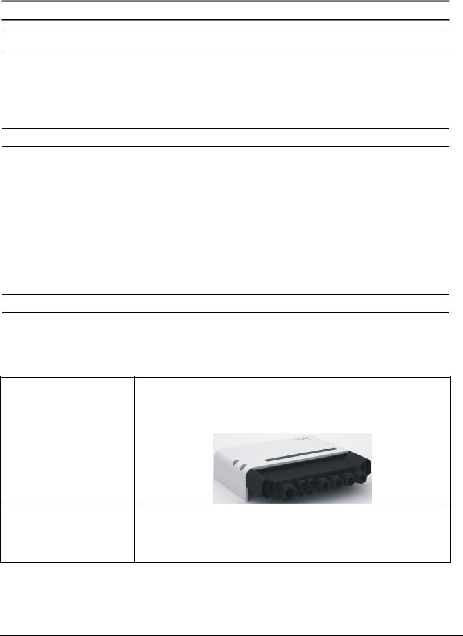
UHF Long Range Reader
final – public (B)
2014-03-18 – M31010-1e-ID-B.docx

OBID i-scan ® UHF |
Installation |
ID ISC.LRU1002 |
Note
Copyright 2013-14 by
FEIG ELECTRONIC GmbH Lange Strasse 4
D-35781 Weilburg Tel.: +49 6471 3109-0 http://www.feig.de
With the edition of this document, all previous editions become void. Indications made in this manual may be changed without previous notice.
Copying of this document, and giving it to others and the use or communication of the contents thereof are forbidden without express authority. Offenders are liable to the payment of damages. All rights are reserved in the event of the grant of a patent or the registration of a utility model or design.
Composition of the information in this document has been done to the best of our knowledge. FEIG ELECTRONIC GmbH does not guarantee the correctness and completeness of the details given in this manual and may not be held liable for damages ensuing from incorrect or incomplete information. Since, despite all our efforts, errors may not be completely avoided, we are always grateful for your useful tips.
The instructions given in this manual are based on advantageous boundary conditions. FEIG ELECTRONIC GmbH does not give any guarantee promise for perfect function in cross environments and does not give any guaranty for the functionality of the complete system which incorporates the subject of this document.
FEIG ELECTRONIC call explicit attention that devices which are subject of this document are not designed with components and testing methods for a level of reliability suitable for use in or in connection with surgical implants or as critical components in any life support systems whose failure to perform can reasonably be expected to cause significant injury to a human. To avoid damage, injury, or death, the user or application designer must take reasonably prudent steps to protect against system failures.
Use Exclusion in Transportation Market: Devices which are subject of this document may NOT be sold, used, leased, offer for sale, or otherwise transferred, exported, and imported by anyone in the Transportation
Market. “Transportation Market” means (i) Electronic Toll and Traffic Management (ETTM), (ii) Public Sector
Vehicle Registration, Inspection and Licensing Programs, (iii) Railroad Locomotive and Wagon tracking, (iv) airport based ground transportation management systems (GTMS) and taxi dispatch, (v) revenue based parking, and (vi) vehicle initiated mobile payment applications, where the RFID sticker/tag is initially attached to the vehicle but not incorporated at the point of vehicle manufacture.
FEIG ELECTRONIC GmbH assumes no responsibility for the use of any information contained in this document and makes no representation that they free of patent infringement. FEIG ELECTRONIC GmbH does not convey any license under its patent rights nor the rights of others.
OBID® and OBID i-scan® are registered trademarks of FEIG ELECTRONIC GmbH.
FEIG ELECTRONIC GmbH |
Page 2 of 29 |
M31010-1e-ID-B.docx |

OBID i-scan ® UHF |
Installation |
ID ISC.LRU1002 |
|
Contents |
|
1. Safety Instructions / Warning - Read before start-up ! |
5 |
|
2. Performance Features of Reader Family ID ISC.LRU1002 |
6 |
|
2.1. Performance features........................................................................................................ |
|
6 |
2.2. Available Reader types ..................................................................................................... |
|
6 |
2.3. Available Accessories....................................................................................................... |
|
6 |
3. Installation |
|
7 |
4. Terminals |
|
8 |
4.1. Antenna Connection ......................................................................................................... |
|
9 |
4.2. Power Supply................................................................................................................... |
|
10 |
4.2.1. Power Supply via connection X2 ................................................................................ |
10 |
|
4.3. Interfaces ......................................................................................................................... |
|
11 |
4.3.1. Ethernet Interface on connector X1............................................................................ |
11 |
|
4.3.2. USB Interface on connector X3 |
.................................................................................. |
11 |
4.3.3. RS232 Interface on connector X4 .............................................................................. |
12 |
|
4.3.4. Data-Clock Interface on connector X4........................................................................ |
13 |
|
4.4. Digital Input on connector X4 ......................................................................................... |
|
15 |
4.5. Outputs on connector X4................................................................................................ |
|
16 |
4.5.1. Digital outputs on connector X4 ................................................................................. |
16 |
|
4.5.2. Relay output on connector X4 .................................................................................... |
|
18 |
5. Operating and Display Elements |
|
19 |
5.1. Status LEDs ..................................................................................................................... |
|
19 |
5.2. Reset Push Buttons ........................................................................................................ |
|
20 |
5.3. Reader Power adjustment............................................................................................... |
|
21 |
5.3.1. EU-Reader according to EN302 208 .......................................................................... |
21 |
|
5.3.2. FCC-Reader according to FCC 47 Part 15................................................................. |
22 |
|
FEIG ELECTRONIC GmbH |
Page 3 of 29 |
M31010-1e-ID-B.docx |

OBID i-scan ® UHF |
Installation |
ID ISC.LRU1002 |
6. Technical Data |
|
23 |
7. Radio Approvals |
|
26 |
7.1. Europe (CE)...................................................................................................................... |
|
26 |
7.2. Declaration of Conformity (Directive 1999/5/EC - R&TTE) |
............................................ 27 |
|
7.3. USA (FCC) and Canada (IC) ............................................................................................ |
|
28 |
7.3.1. USA (FCC) and Canada (IC) warning notices ............................................................ |
28 |
|
7.3.2. Label Information ....................................................................................................... |
|
29 |
7.3.3. Installation with FCC / IC Approval............................................................................. |
29 |
|
7.3.4. USA (FCC) and Canada (IC) approved antennas ...................................................... |
29 |
|
FEIG ELECTRONIC GmbH |
Page 4 of 29 |
M31010-1e-ID-B.docx |

OBID i-scan ® UHF |
Installation |
ID ISC.LRU1002 |
1. Safety Instructions / Warning - Read before start-up !
The device may only be used for the intended purpose designed by for the manufacturer.
The operation manual should be conveniently kept available at all times for each user.
Unauthorized changes and the use of spare parts and additional devices which have not been sold or recommended by the manufacturer may cause fire, electric shocks or injuries. Such unauthorized measures shall exclude any liability by the manufacturer.
The liability-prescriptions of the manufacturer in the issue valid at the time of purchase are valid for the device. The manufacturer shall not be held legally responsible for inaccuracies, errors, or omissions in the manual or automatically set parameters for a device or for an incorrect application of a device.
Repairs may only be executed by the manufacturer.
Installation, operation, and maintenance procedures should only be carried out by qualified personnel.
Use of the device and its installation must be in accordance with national legal requirements and local electrical codes .
When working on devices the valid safety regulations must be observed.
Special advice for carriers of cardiac pacemakers:
Although this device doesn't exceed the valid limits for electromagnetic fields you should keep a minimum distance of 25 cm between the device and your cardiac pacemaker and not stay in an immediate proximity of the device respective the antenna for some time.
FEIG ELECTRONIC GmbH |
Page 5 of 29 |
M31010-1e-ID-B.docx |
OBID i-scan ® UHF |
Installation |
ID ISC.LRU1002 |
2. Performance Features of Reader Family ID ISC.LRU1002
2.1. Performance features
The Reader has been developed for reading passive data carriers, so-called „Smart Labels“, using an operating frequency in the UHF range. The output power is configurable in steps of 100 mWatts in the range between 100 mWatts and 2 Watts. This allows read ranges of up to 8m.
2.2. Available Reader types
The following Readers are available:
Table 1: Available Reader Types
Reader type |
Description |
ID ISC.LRU1002-EU |
Device version for Europe |
|
|
ID ISC.LRU1002-FCC |
Device version for USA |
|
|
2.3. Available Accessories
The following optional accessories are currently available:
Table 2: Optional Reader Accessories
Reader type |
Description |
|
|
Protection cap for IP 64
Art.No.: 3558.000.00
ID ISC.LR.CSC-IP64 Connector
Sealing Cap
ID ISC.LRU3x00-MS Mounting |
Rail Mounting Set for ID ISC.LRU1002 and ID ISC.LRU3000/3500 |
|
|
Rail Set |
Art.No.: 3831.000.00 |
|
FEIG ELECTRONIC GmbH |
Page 6 of 29 |
M31010-1e-ID-B.docx |
OBID i-scan ® UHF |
Installation |
ID ISC.LRU1002 |
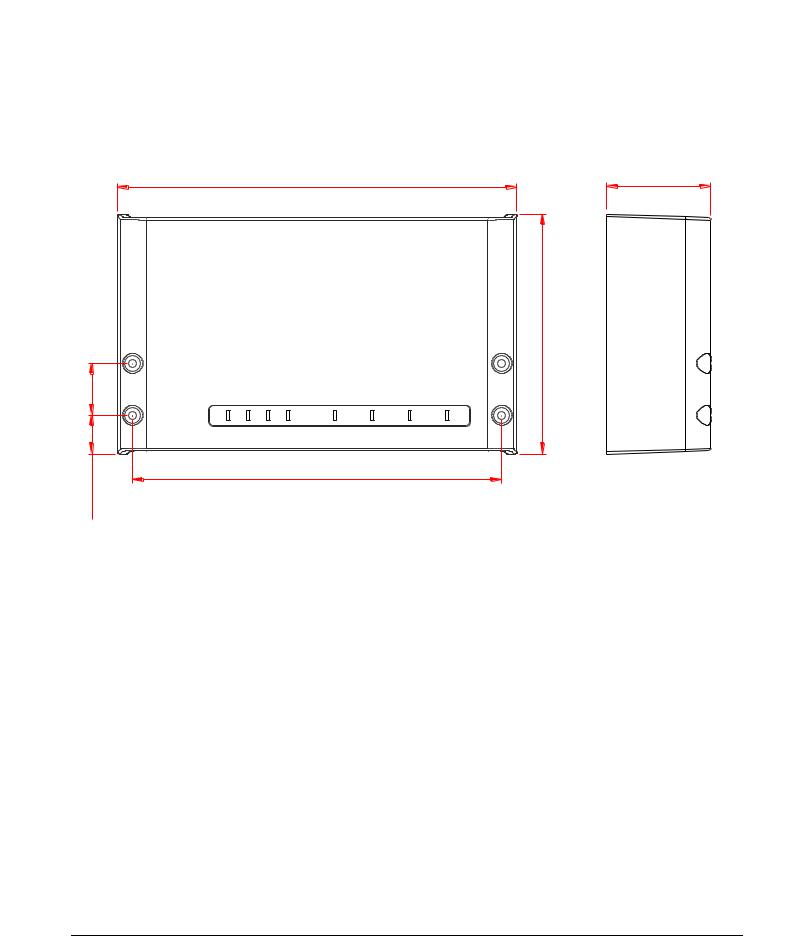
3. Installation
The Reader is designed for wall-mount, including outdoors. Holes for mounting on a wall are provided in the housing.
It is not necessary to open the reader housing for mounting.
|
261,3 (10.29) |
68 (2.68) |
|
|
157,3 (6.19) |
34 (1.34) |
|
|
(1.00)25,5 |
241,7 (9.52) |
|
|
|
Figure 1: Installation Drawing
FEIG ELECTRONIC GmbH |
Page 7 of 29 |
M31010-1e-ID-B.docx |
OBID i-scan ® UHF |
Installation |
ID ISC.LRU1002 |
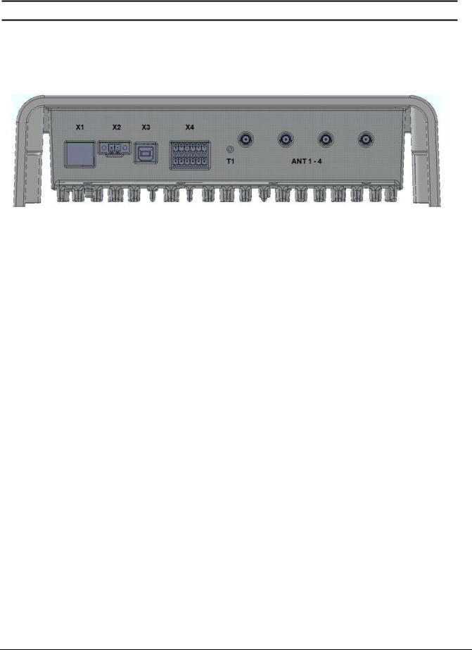
4. Terminals
On the lower side of the reader housing the different cable connectors are positioned. Figure 2: Connection Overview shows the arrangement of the connectors and Table 3: Connection terminals shows which connection for the different cables are used. Table 4: Push button function shows the available push buttons.
|
|
|
|
Figure 2: Connection Overview |
|
Table 3: Connection terminals |
|
|
|||
|
|
|
|
|
|
|
Connector |
|
Description |
|
|
|
|
|
|
|
|
|
ANT 1-4 |
|
Connection of the external antennas (Impedance 50 ) |
|
|
|
|
|
|
|
|
|
X1 |
|
10/100Tbase network connection with RJ-45 |
|
|
|
|
|
|
|
|
|
X2 |
|
Power supply 24VDC +-5% |
|
|
|
|
|
|
|
|
|
X3 |
|
USB interface for host communication |
|
|
|
|
|
|
|
|
|
X4 |
|
Digital input, digital output, relay output and RS232 interface |
|
|
|
|
|
|
|
|
Table 4: Push button function |
|
|
|||
|
|
|
|
||
|
Push button |
Description |
|
||
|
|
|
|
|
|
|
T1 |
|
|
Internal push button for complete configuration reset |
|
|
|
|
|
|
|
FEIG ELECTRONIC GmbH |
Page 8 of 29 |
M31010-1e-ID-B.docx |
OBID i-scan ® UHF |
Installation |
ID ISC.LRU1002 |
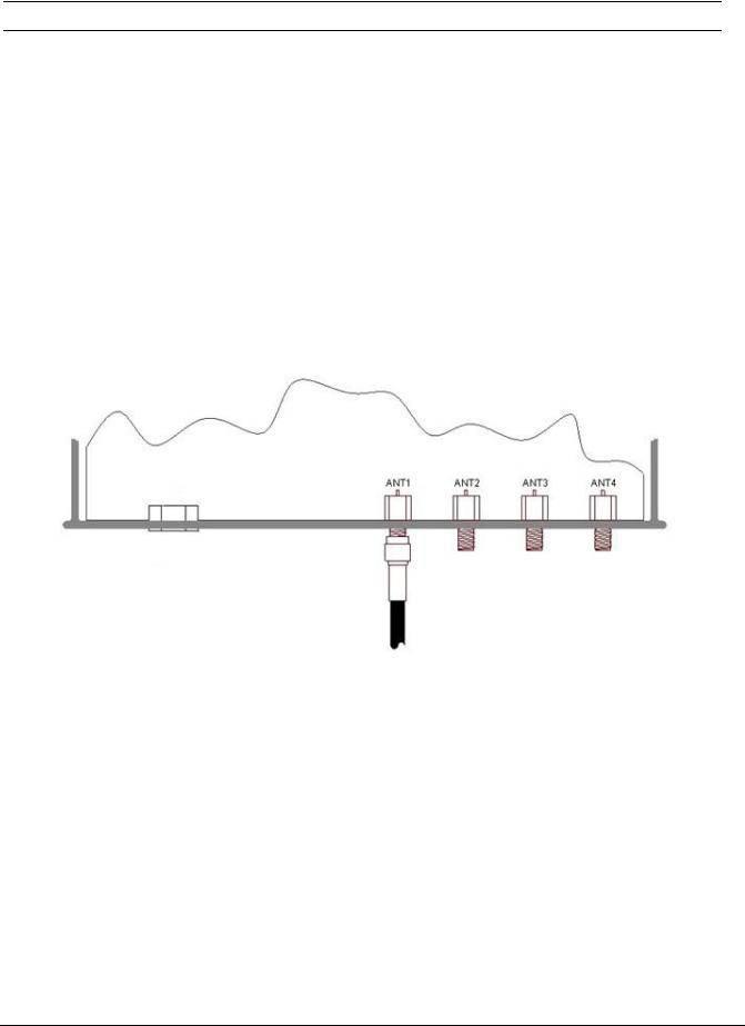
4.1. Antenna Connection
The external SMA antenna connectors are positioned on the lower side of the reader. The maximum tightening torque for the SMA sockets is 0.45 Nm (4.0 lbf in).
CAUTION:
Exceeding the tightening torque will destroy the plug.
Table 5: External antenna connection
Terminal |
Description |
|
|
ANT 1 - 4 |
Connection for external antennas (input impedance 50 ) |
|
|
Figure 3: External antenna connection ANT1-4
FEIG ELECTRONIC GmbH |
Page 9 of 29 |
M31010-1e-ID-B.docx |
 Loading...