

Feig Electronic OBID i-scan ID ISC.ANT1700/740-A, OBID i-scan ID ISC.ANT1700/740-B, OBID i-scan ID ISC.LRM2500-B Installation Manual
INSTALLATION
final
public (B)
2011-09-29
M91201-5e-ID-B.doc
ID ISC.ANT1700/740-A /-B
Clear Gate
Version : Reader ID ISC.LRM2500-B
English

OBID i-scan®
Installation
ID ISC.ANT1700/740-A /-B
FEIG ELECTRONIC GmbH
Page 2 of 74
M91201-5e-ID-B.doc
Note
Copyright 2010-2011 by
FEIG ELECTRONIC GmbH
Lange Strasse 4
D-35781 Weilburg
Tel.: +49 6471 3109-0
http://www.feig.de
With the edition of this document, all previous editions become void. Indications made in this manual may be
changed without previous notice.
Copying of this document, and giving it to others and the use or communication of the contents thereof are
forbidden without express authority. Offenders are liable to the payment of damages. All rights are reserved
in the event of the grant of a patent or the registration of a utility model or design.
Composition of the information in this document has been done to the best of our knowledge. FEIG
ELECTRONIC GmbH does not guarantee the correctness and completeness of the details given in this
manual and may not be held liable for damages ensuing from incorrect or incomplete information. Since,
despite all our efforts, errors may not be completely avoided, we are always grateful for your useful tips.
The instructions given in this manual are based on advantageous boundary conditions. FEIG ELECTRONIC
GmbH does not give any guarantee promise for perfect function in cross environments and does not give
any guaranty for the functionality of the complete system which incorporates the subject of this document.
FEIG ELECTRONIC call explicit attention that devices which are subject of this document are not designed
with components and testing methods for a level of reliability suitable for use in or in connection with surgical
implants or as critical components in any life support systems whose failure to perform can reasonably be
expected to cause significant injury to a human. To avoid damage, injury, or death, the user or application
designer must take reasonably prudent steps to protect against system failures.
FEIG ELECTRONIC GmbH assumes no responsibility for the use of any information contained in this document and makes no representation that they free of patent infringement. FEIG ELECTRONIC GmbH does
not convey any license under its patent rights nor the rights of others.
OBID® and OBID i-scan® are registered trademarks of FEIG ELECTRONIC GmbH.
I-CODE® is a registered trademark of Philips Electronics N.V.
Tag-itTM is a registered trademark of Texas Instruments Incorporated.

OBID i-scan®
Installation
ID ISC.ANT1700/740-A /-B
FEIG ELECTRONIC GmbH
Page 3 of 74
M91201-5e-ID-B.doc
Contents
1 Safety Instructions / Warning - Read before Start-Up ! 5
2 Maintenance 6
3 Performance Features of the ID ISC.ANT1700/740 Antennas 7
3.1 Performance Features of the People Counter ID ISC.ANT1700/740-GPC ............... 8
3.2 Available Antenna Types ......................................................................................... 11
4 Installation and Wiring 13
4.1 Mounting preparation .............................................................................................. 14
4.2 Dimensions of antenna ............................................................................................ 15
4.3 Drilling the Mounting Holes ..................................................................................... 16
4.4 Installing the Antenna Base and Antenna Body ..................................................... 18
5 Typical Antenna Configuration (Gate Antenna with two Antennas) 19
5.1 Project Notes Antenna ............................................................................................. 19
5.1 Project Notes People Counter (GPC) ...................................................................... 22
5.2 Gate Configuration and Setup using Antennas Type -A and -B ............................ 24
5.2.1 Required Components ........................................................................................... 24
5.2.2 Configuration of a Gate antenna with Multiplexer ................................................... 25
5.2.3 Setting the Multiplexer ............................................................................................ 27
5.2.4 Setting the Antenna Tuner ..................................................................................... 28
5.2.5 Interface Connections ............................................................................................ 30
5.2.5.1 RS 232 ......................................................................................................... 30
5.2.5.2 LAN / TCP/IP ................................................................................................ 31
5.2.6 Reader Configuration with Multiplexer .................................................................... 32
5.2.7 Tuning the Gate Antenna with Multiplexer .............................................................. 35
5.3 Testing the Gate Antenna......................................................................................... 36
5.3.1 Checking the Noise Level ....................................................................................... 36
5.3.2 Reading a Serial Number ....................................................................................... 38

OBID i-scan®
Installation
ID ISC.ANT1700/740-A /-B
FEIG ELECTRONIC GmbH
Page 4 of 74
M91201-5e-ID-B.doc
5.3.3 Testing the performance ........................................................................................ 39
5.4 Setting the Alarm indicators (Alarm sounder and Alarm LED lights) ................... 41
5.4.1 Reader Setting for Indicator.................................................................................... 42
5.4.2 Programming a Transponder with the AFI Byte ...................................................... 44
5.5 Activating the Automatic Mode................................................................................ 45
6 Installation of the Gate People Counter ID ISC.ANT1700/740-GPC 46
6.1 Installation and Connections ................................................................................... 46
6.2 Installation ID ISC.ANT.GPC-E ................................................................................. 53
6.3 Configuration and Test ............................................................................................. 56
6.3.1 Connecting several People Counter ....................................................................... 57
6.3.2 Configuration and Test in ISO-Host or Buffered Read ............................................ 58
6.3.3 Configuration and Test in Notification Mode ........................................................... 60
7 Configuring the Reader in accordance with national RF regulations 62
8 Technical Data 64
8.1 Antenna ID ISC.ANT1700/740 Type A and B ........................................................... 64
8.2 People Counter ID ISC.ANT1700/740-GPC and ID ISC.ANT.GPC-E ...................... 67
8.3 Approval .................................................................................................................... 68
8.3.1 Europe (CE) ........................................................................................................... 68
8.3.1.1 Antenna ID ISC.ANT1700/7400 .................................................................... 68
8.3.1.2 People Counter ID ISC.ANT1700/740-GPC ................................................ 68
8.3.2 USA (FCC) and Canada (IC) .................................................................................. 69
8.3.2.1 Antenna ID ISC.ANT1700/740 ...................................................................... 69
8.3.2.2 People Counter ID ISC.ANT1700/740-GPC ................................................. 70
8.3.3 USA and Canada (UL) ........................................................................................... 71
9 Annex A 72
9.1 Terminal assignment “Terminal Board” .................................................................. 72
9.1 Internal wiring ........................................................................................................... 74

OBID i-scan®
Installation
ID ISC.ANT1700/740-A /-B
FEIG ELECTRONIC GmbH
Page 5 of 74
M91201-5e-ID-B.doc
1 Safety Instructions / Warning - Read before Start-Up !
The device may only be used for the intended purpose designed by for the manufacturer.
The operation manual should be conveniently kept available at all times for each user.
Unauthorized changes and the use of spare parts and additional devices which have not been
sold or recommended by the manufacturer may cause fire, electric shocks or injuries. Such
unauthorized measures shall exclude any liability by the manufacturer.
The liability-prescriptions of the manufacturer in the issue valid at the time of purchase are valid
for the device. The manufacturer shall not be held legally responsible for inaccuracies, errors,
or omissions in the manual or automatically set parameters for a device or for an incorrect
application of a device.
Repairs may only be executed by the manufacturer.
Installation, operation, and maintenance procedures should only be carried out by qualified
personnel.
Use of the device and its installation must be in accordance with national legal requirements
and local electrical codes .
When working on devices the valid safety regulations must be observed.
Please observe that some parts of the device may heat severely.
Before touching the device, the power supply must always be interrupted. Make sure that the
device is without voltage by measuring. The fading of an operation control (LED) is no indicator
for an interrupted power supply or the device being out of voltage!
For installation and dismantling you should wear suitable safety gloves, because parts of an-
tenna housing could be sharp-edged.
CAUTION! The Antenna-Tuner and the Antenna conductor carry voltages up to
1000V.
The Antenna is not water proof and should not be exposed to rain or humidity.
Under extreme circumstances water could seep into the antenna and damage the electronic
circuits.
Special advice for wearers of cardiac pacemakers:
Although this device doesn't exceed the valid limits for electromagnetic fields you should
keep a minimum distance of 25 cm between the device and your cardiac pacemaker and
not stay in an immediate proximity of the reader’s antennas for any length of time.

OBID i-scan®
Installation
ID ISC.ANT1700/740-A /-B
FEIG ELECTRONIC GmbH
Page 6 of 74
M91201-5e-ID-B.doc
2 Maintenance
The antenna ID ISC.ANT1700/740 is a design product with high quality surfaces, and should always be handled with caution. The antenna was designed to work reliably and flawlessly for years
without special maintenance.
Attention! The surfaces should be cleaned with a clean, soft cloth dampened in a
dishwashing liquid – water solution. The use of alcohol, spirit, thinners, glass clean-
ers or other harsh cleaning liquids is prohibited and will damage the housing.
To improve the durability and the appearance, please follow the instructions below:
Keep the antenna clean and take caret the antenna is not scratched.
Regularly remove dust and other impurities with a soft cloth and a solution of water with a little
dishwashing liquid.
Keep the antenna dry. All kinds of moisture should be avoided during operation and storage.
Precipitation, humidity and liquids contain minerals that will corrode electronic circuits and damaging transparent plastic parts.
Protect the antenna from high temperatures. Mount the antenna away from heaters and other
heat sources. Operation under direct sunlight can cause extreme high temperatures and a fading cause of the surface.
Avoid storing or operating the antenna at dirty or wet locations. The surfaces or electronic
components may be-damaging.
Handle the device with care. Shocks may break internal circuit boards.
Do not try to open the antenna during operation or outside maintenance periods. Non-
professional management can result in damage to the device.
If any device not working properly, please contact the appropriate representative.

OBID i-scan®
Installation
ID ISC.ANT1700/740-A /-B
FEIG ELECTRONIC GmbH
Page 7 of 74
M91201-5e-ID-B.doc
3 Performance Features of the ID ISC.ANT1700/740 Antennas
The ID ISC.ANT1700/740-A antenna is a version with DynamicTuning Board ID ISC.DAT , Long
Range Reader ID ISC.LRM2500-B, 4- times Multiplexer Module ID ISC.ANT.MUX M4 and
additional signal light and buzzer already mounted.
The ID ISC.ANT1700/740-B antenna is a version with DynamicTuning Board ID ISC.DAT and
signal light mounted.
Up to
- two antennas with reader and multiplexer as a single gate,
- three to four antennas with reader and multiplexer as a double gate or triple gate
- up to 8 antennas as multiple gate with up to 7 aisle at the use of the 8-times Multiplexer
ID ISC.ANT-MUX M8.
can be operated.
Depending on the antenna configuration, one, two or all three read orientations of the Smart Tags
and various antenna spacing (gate widths) are possible.
The ID ISC.ANT1700/740-A/B is a „figure-of-eight“ antenna with tuner and have been optimized as
transmitting and receiving antennas for the ID ISC.LRM2500 Reader. It is however also possible to
operate them with other Readers at a transmission frequency of 13.56 MHz and an output
impedance of 50 . The read ranges indicated in this document and the tuning procedures may
however then vary.
The antennas comprise the electrical antenna conductor, the housing, the ID ISC.DAT Dynamic
Antenna Tuner and the connection cable. The antennas are factory tuned to an impedance of 50
in a magnetically neutral environment at a distance of 95 cm. When installing in different ambient
conditions the antenna can be retuned using the “DATuningTool“ PC software. After tuning the
antennas will retain their settings as long as the ambient conditions remain unchanged.
The antennas can be used for detecting both product and persons. It is suitable for installation
indoors or outdoors if weather-protected.
OBID i-scan®
Installation
ID ISC.ANT1700/740-A /-B
FEIG ELECTRONIC GmbH
Page 8 of 74
M91201-5e-ID-B.doc
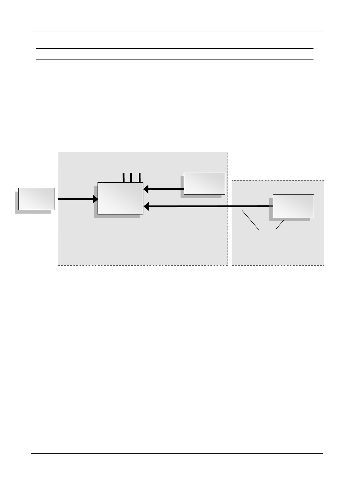
People
Counter 1
Radar
Detector 1
Out / LED 1-3
ID ISC.ANT.GPC-E
Extension Radar Detector
(e.g. 2‟nd aisle of the gate)
Radar
Detector 2
Two gate antennas
ID ISC.ANT1700/740-GPC
Reader
3.1 Performance Features of the People Counter ID ISC.ANT1700/740-GPC
The product ID ISC.ANT1700/740-GPC, short form “Gate People Counter” or “GPC”, are made for
mounting in the gate antennas ID ISC.ANT1700/740.
A Gate People Counter consist of a People Counter board (PC) and one Radar Detector! The
product ID ISC.ANT.GPC-E Extension Radar Detector is used to extend the People Counter to a
second gate aisles.
The People Counter has two counters per aisle. The values of the incoming and out going persons
will be separately captured.
Fig. 1: Gate People Counter Structure (2-3 antennas, 1-2 gate aisles)
A change of the counter values will be stored in the EEPROM of the People Counter Board. With
the command “0x78 Set People Counter” the values could be set/reset to the needed value.
OBID i-scan®
Installation
ID ISC.ANT1700/740-A /-B
FEIG ELECTRONIC GmbH
Page 9 of 74
M91201-5e-ID-B.doc
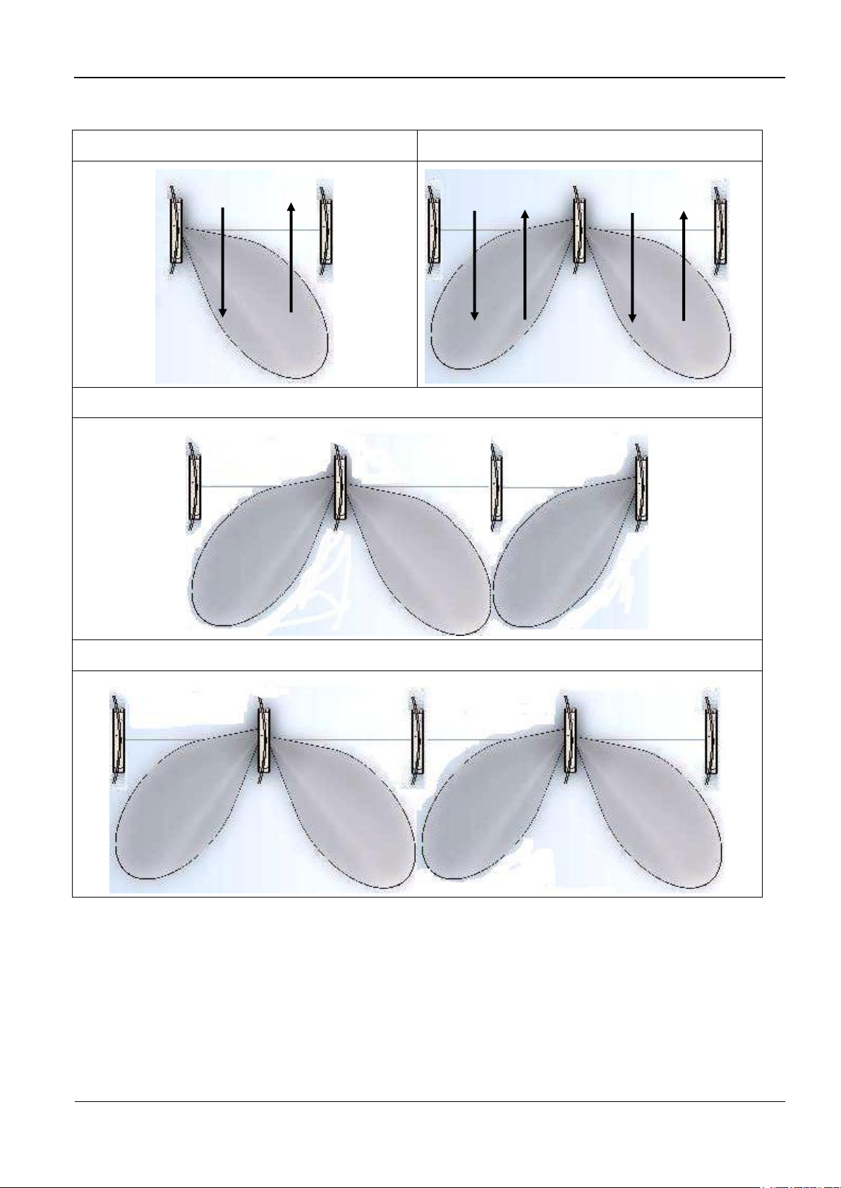
Radar Detection zone of a single gate
Radar Detection zone with two aisles
Radar Detection zone with three aisles
Radar Detection zone with four aisles
Counter 1 | Counter 2
In | Out
Cnt. 1 | Cnt. 2
In | Out
Cnt. 3 | Cnt. 4
In | Out
Fig. 2: Top view of the detection areas (2-3 antennas, 1-2 gate aisles)
The People Counter board and the Radar detectors are mounted in the base of the antennas. Due
to the radar beam can pervade the plastic housing of the antenna, no openings a necessary.
The three digital output can be used, to enable a signal light at every gate antenna or activate an
alarm buzzer in the gate antenna.
The Connection between reader and people counter takes place trough the RS485 Interface of the
reader.

OBID i-scan®
Installation
ID ISC.ANT1700/740-A /-B
FEIG ELECTRONIC GmbH
Page 10 of 74
M91201-5e-ID-B.doc
There is no need of a direct connection from the GPC to the Host. All commands from the Host to
the People Counters are embedded in the Pickyback Command of the reader.
In the reader modes ISO Host or Buffered Read Mode, the host has to poll the GPC by sending
protocols to the reader. Only, in the Notification Mode, the reader poll the counter values, automatically, and send data according the reader configuration to the host.
So, there are two possibilities to get the actual people counter values. Either the Host poll the
People Counter periodically or in the Notification Mode of the reader, the reader send a notification
protocol at any change of the counter values.
See also System Manual H01011-0e-ID-B.DOC

OBID i-scan®
Installation
ID ISC.ANT1700/740-A /-B
FEIG ELECTRONIC GmbH
Page 11 of 74
M91201-5e-ID-B.doc
Antenna Type
Description
Picture
ID ISC. ANT1700/740-A
Clear Gate
Antenna with Reader, Multiplexer ,
dynamic tuning board, signal light and
buzzer
ID ISC. ANT1700/740-B
Clear Gate
Antenna with dynamic tuning board
ID ISC.DAT and signal light
ID ISC. ANT1700/740-AGP
Acrylic glass plate window for
Clear antennas
ID ISC.ANT1700/740-GPC
Gate People Counter
People Counter and one piece of radar detector for antenna
ID ISC.ANT1700/740 incl. Mounting and cabling set. (optional)
ID ISC.ANT.GPC-E
Extension Radar Detector
Second radar detector with cable for the second direct parallel aisle
(optional)
3.2 Available Antenna Types
The following products are currently available:
Table 1: Available Antenna Types and Accessories

OBID i-scan®
Installation
ID ISC.ANT1700/740-A /-B
FEIG ELECTRONIC GmbH
Page 12 of 74
M91201-5e-ID-B.doc
Number of
antennas
Antenna
People Counter (Optional)
ID ISC.
ANT1700/740
-A
ID ISC.
ANT1700/740
-B
ID ISC.
ANT1700/
740-GPC
ID ISC.ANT.
GPC-E
Note
2 Antennas
1 1 1
3 Antennas
1 2 1 1
4 Antennas
1 3 2 1
5 Antennas
1 4 2 2 8 Chanel
Multiplexer
6 Antennas
1 5 3 2 8 Chanel
Multiplexer
7 Antennas
1 6 3 3 8 Chanel
Multiplexer
Needed components for at the usage of the Gate People Counter:
Table 2 Needed components for gates with People Counter

OBID i-scan®
Installation
ID ISC.ANT1700/740-A /-B
FEIG ELECTRONIC GmbH
Page 13 of 74
M91201-5e-ID-B.doc
4 Installation and Wiring
Notes:
Before installing the antennas please read 5.1 Project Notes . The spacing of the antennas
in a gate depends on the antenna configuration.
If multiple antennas or gates are connected to different readers, a minimum clearance of
8 m must be kept between the antennas or gates. For shorter distances (1 m – 8 m) the
readers must be synchronized. The synchronization of the readers (see application note
N10311-xe-ID-B.doc) is only possible in one of the Automatic Modes (Buffered Read,
Notification or Scan Mode). Below a distance of 1.5 m the antennas must also be shielded
from each other. Otherwise the read range will be significantly reduced. The antennas must
have a minimum distance of 20 cm to all larger metal parts! At a distance of less than 50 cm
between the antenna and metal parts the read range will be significantly reduced.
OBID i-scan®
Installation
ID ISC.ANT1700/740-A /-B
FEIG ELECTRONIC GmbH
Page 14 of 74
M91201-5e-ID-B.doc
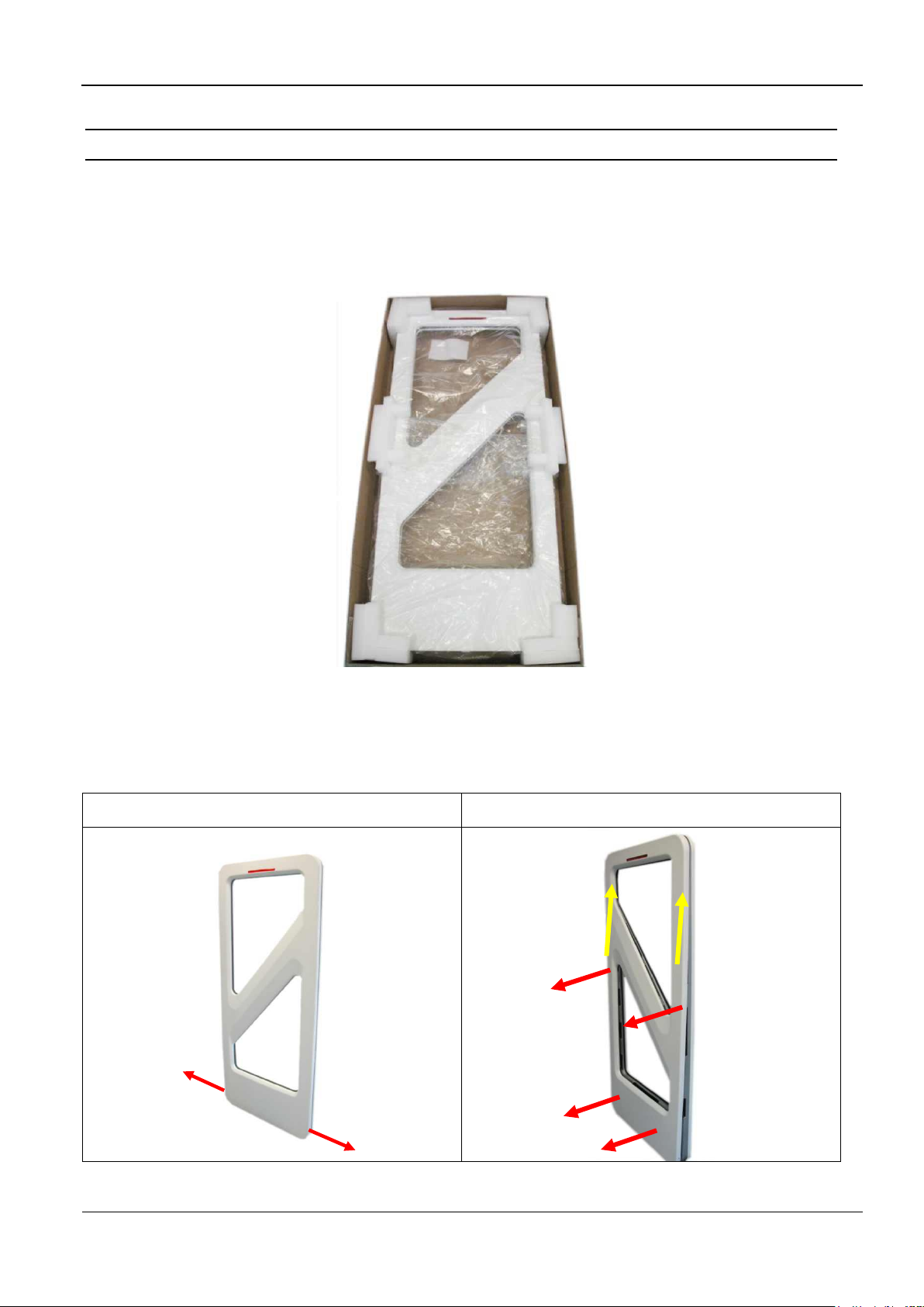
Step 1
Step 2
4.1 Mounting preparation
For assembly the antenna must be carefully unpacked. This is done as described in the following
steps:
1. Place the packed antenna on the floor with the top side facing up. Carefully open the box and
then remove the antenna.
Fig. 3: Antenna in its packaging
2. After that the antenna has to be placed carefully again on the floor. Now you must remove the
two fastening screws (hexagon socket width A/F2,5) of the antenna cover at the antenna foot
and remove it upwards. Fig. 4
Fig. 4: Opening the antenna base
OBID i-scan®
Installation
ID ISC.ANT1700/740-A /-B
FEIG ELECTRONIC GmbH
Page 15 of 74
M91201-5e-ID-B.doc
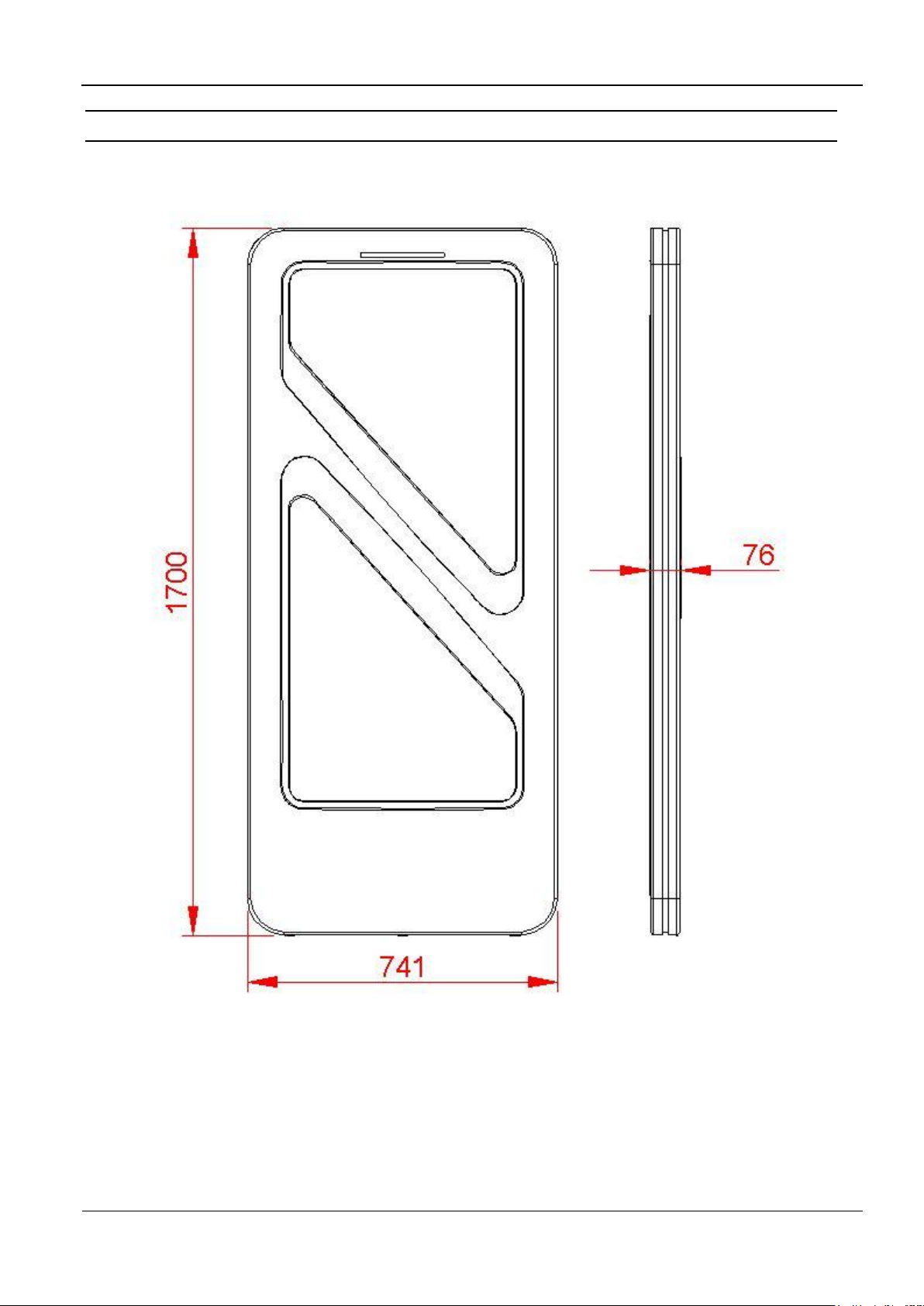
4.2 Dimensions of antenna
The outside dimensions of the antenna are shown in Fig. 5
All dimensions are in mm with general tolerance to ISO 2768 m (mean).
Fig. 5: Antenna outside dimensions
OBID i-scan®
Installation
ID ISC.ANT1700/740-A /-B
FEIG ELECTRONIC GmbH
Page 16 of 74
M91201-5e-ID-B.doc
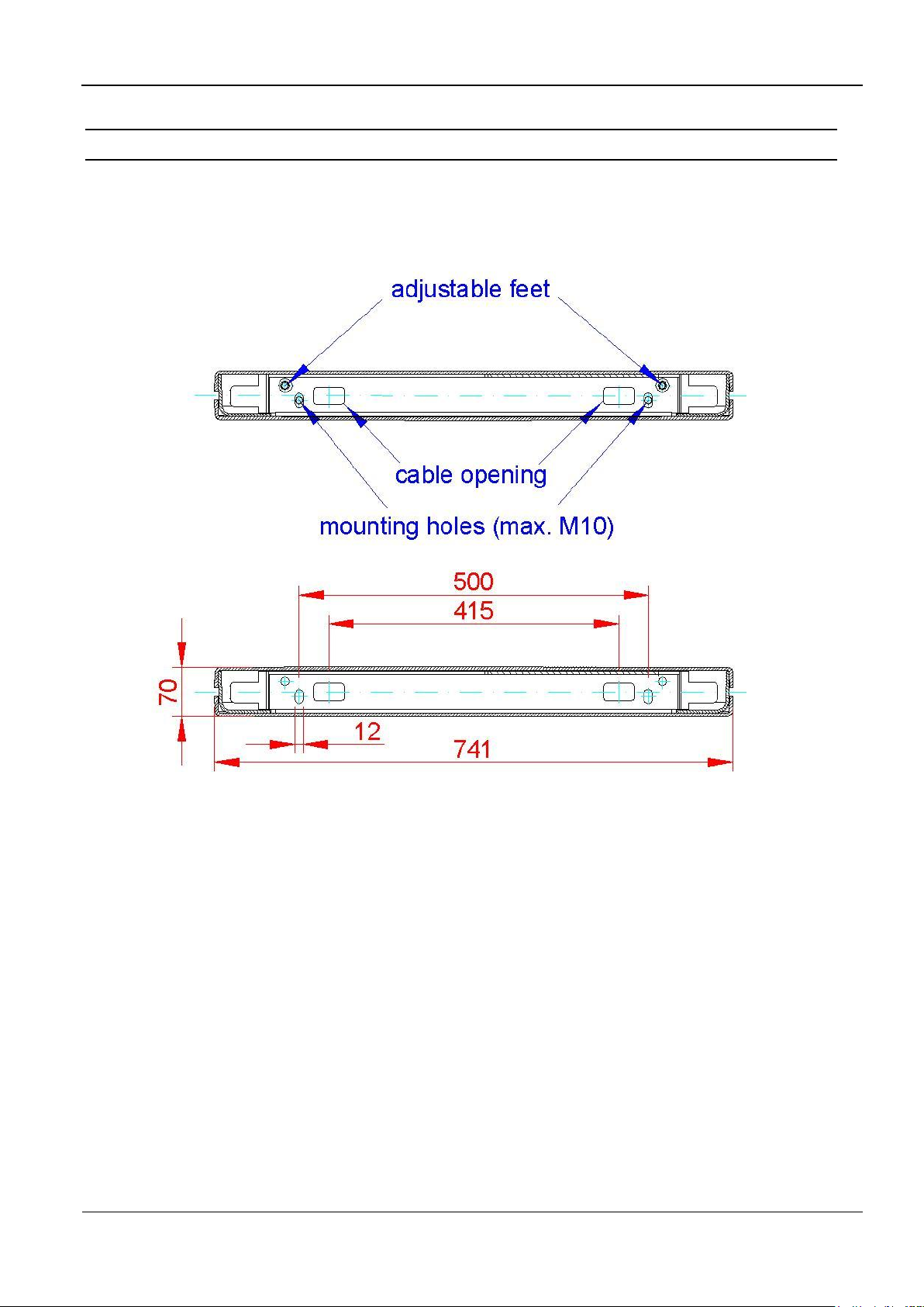
4.3 Drilling the Mounting Holes
If the position of the antennas has been marked or determined a hole template, can be used to
mark and drill the mounting holes and the holes for the cable entry. The dimensions are shown in
Fig. 6:
Fig. 6: Floor plate dimensions
All dimensions are in mm with general tolerance to ISO 2768 m (middle).
The size and type of the screw anchors depends considerably on the strength of the base or floor.
The anchors should be capable of withstanding a permissible load of at least 5 kN per anchor for
all load directions (e.g. for concrete floor Hilti HVA anchors with HAS-(E) M8 threaded rod or Hilti
HIS-N M8 (5/16”) threaded inserts). The size of the mounting holes in the antenna is 10 mm (.39”).
The length of the anchors or bolts should be selected such that they extend at least 50 mm (2.0”)
and a maximum of 65 mm (2.6”) from the floor.
Please follow the mounting instructions of the anchor manufacturer!
Two cable openings are provided for the necessary connection cable (see Fig. 6). The cable
openings are dimensioned such that up to 10 cables having a diameter of 6 mm can be passed
through each opening.
OBID i-scan®
Installation
ID ISC.ANT1700/740-A /-B
FEIG ELECTRONIC GmbH
Page 17 of 74
M91201-5e-ID-B.doc
We recommend routing the antenna cables through the cable opening on the Multiplexer side. All
other cables such as the supply voltage and synchronization cable should be routed through the
cable opening on the Reader side.
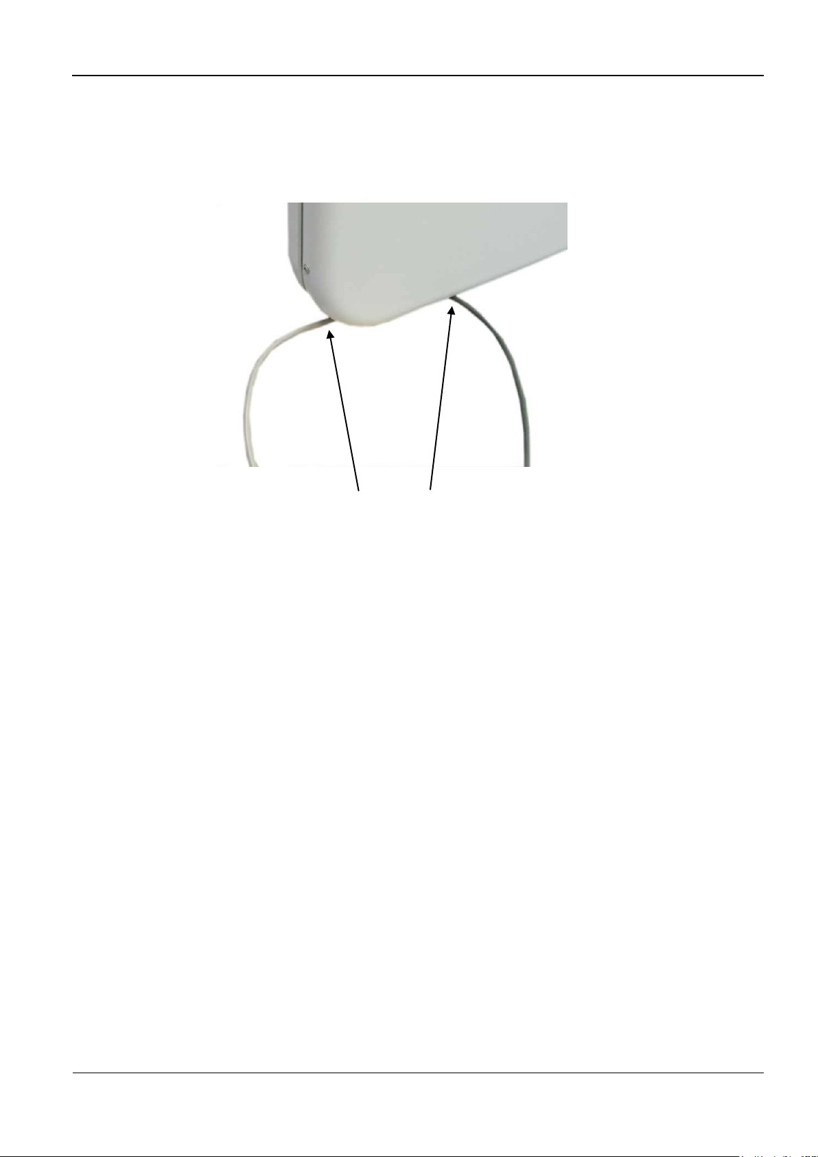
Alternatively the cables can be routed at the sides of the antenna bas like shown in Fig. 7
Fig. 7 Cable routing at the antenna sides
OBID i-scan®
Installation
ID ISC.ANT1700/740-A /-B
FEIG ELECTRONIC GmbH
Page 18 of 74
M91201-5e-ID-B.doc
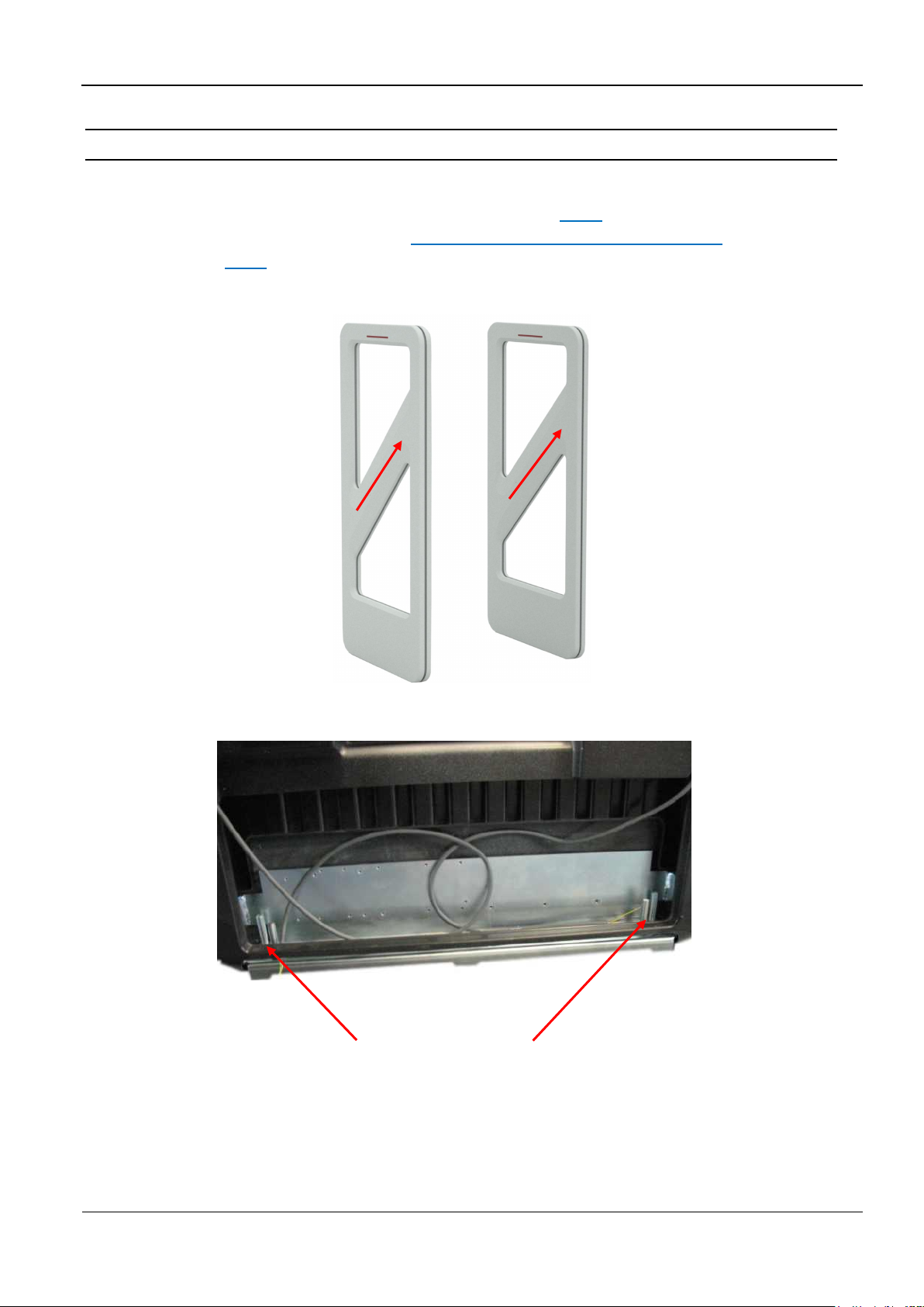
4.4 Installing the Antenna Base and Antenna Body
The antenna will be screwed on the floor. The transverse antenna conductors in the middle of the
antenna body have to face the same direction at all antennas (Fig. 8). If a People Counter
installed in the antenna, then note chapter 5.2 Project Notes People Counter (GPC). Use the
adjusting screws (Fig. 9) to align the antenna vertically.
Fig. 8 Transverse conductors facing same direction
Adjusting screws (hexagon socket width A/F4)
Fig. 9: Attaching and aligning the antenna
OBID i-scan®
Installation
ID ISC.ANT1700/740-A /-B
FEIG ELECTRONIC GmbH
Page 19 of 74
M91201-5e-ID-B.doc
GD
20 cm
5 Typical Antenna Configuration (Gate Antenna with two Antennas)
The standard configuration of a gate with three-dimensional tag orientation consists of one antenna
ID ISC.ANT1700/740 Type A with reader and multiplexer and one antenna ID ISC.ANT1700740
Type B. If a tag moves, at horizontal line, through the gate, it can be read at least once. This
ensures high reliability of the antenna system.
5.1 Project Notes Antenna
The antenna configuration as described allows detection of a tag moving horizontally through the
capture area of the gate. The tag orientation is non-critical. The tags are detected along a
horizontal axis of motion in certain regions within the antennas. The area of detection depends on
the tag orientation.
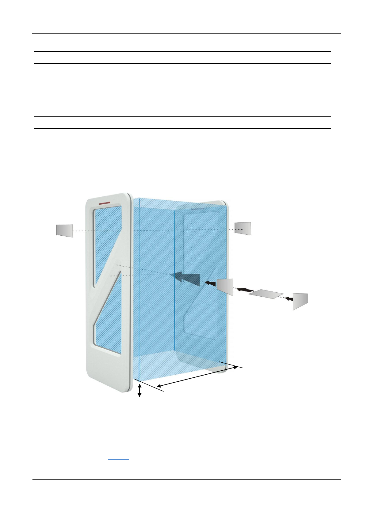
The size of the three-dimensional capture area of the antennas is shown in the sketch below.
Notes:
Note that the entire capture area of the antenna is larger than the three-dimensional area
shown in the drawing (Fig. 11) . This means there are tag orientations in which the tag can
be detected outside the capture area.
Fig. 10: Capture area and tag orientation
OBID i-scan®
Installation
ID ISC.ANT1700/740-A /-B
FEIG ELECTRONIC GmbH
Page 20 of 74
M91201-5e-ID-B.doc
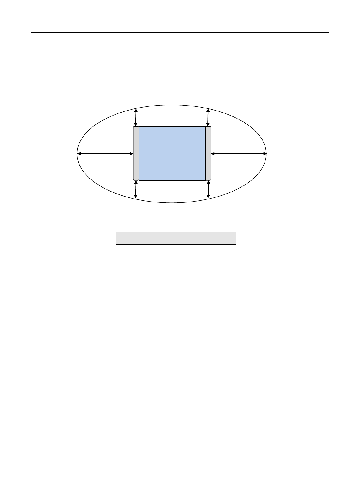
Direction
Minimum Distance
right, left (X=)
80 cm
front, behind (Y=)
35 cm
X
X
Y
Y
To get a optimal performance the reader has to be configured and run in one of the
Automatic Modes (Buffered Read, Notification or Scan Mode).
If multiple gates are arranged with short distances (1-8m) between each other, these will
mutually interfere with each other. In this case, the readers for the individual gates have to
be synchronized and run in one of the automatic modes.
Fig. 11: Top view, capture area outside of the antenna gate
Table 3: Capture area, unintentional detection
To achieve three-dimensional capture of the tag in the capture area drawn above (Fig. 10), the
following conditions must be met:
- The gate distance GD depends on the antenna configuration (see Table 5: ).
- The tags should be at least ISO card size (46 mm x 75 mm).
- The activation field strength of the tags should be less than or equal to 60 mA/m.
- The distance from tag to tag should be greater than 10 cm. If the tag to tag distance is reduced,
the gate distance GD must be reduced correspondingly. This applies in particular to distances
under 5 cm.
- The maximum number of tags (serial number or data) depends on the traverse speed with
which the tags are brought through the capture area of the gate (see Table 5: ). The number of
tags may be increased in the gate distance GD is correspondingly reduced and the maximum
speed adjusted accordingly.
- The antenna should be at least 50 cm from metal parts.
- The minimum distance between the antennas of a gate and antennas of RFID work station or
terminals (transmitting frequency 13,56 MHz) should be:
OBID i-scan®
Installation
ID ISC.ANT1700/740-A /-B
FEIG ELECTRONIC GmbH
Page 21 of 74
M91201-5e-ID-B.doc
Transmitted
output power
Minimum Distance
<0.5W
1 m
0.5W-1.0 W
2 m
1.1 W – 2.0W
3 m
> 2 W
4 m
>= 4 W
8 m
Gate with antenna
Type A and Type B
Gate distance GD
104 cm
Number of tags at a speed of 1 m/s
- Read serial number
- Read data
16
8
Table 4: Minimum Distances
- There should be no interference of the Reader from other electrical devices in the environment.
The Noise Level difference should be less than 20 mV.
- The ID ISC.LRM2500 Reader should be set to an RF power of 8 watts.
- When using ISO 15693 transponders, the Readers should be set as described in 5.3.6 Reader
Configuration .
- If multiple gates are operated at the same time at a distance of less than 8 m, the Readers
must by synchronized. See Application Note Synchronizing RFID Long Range Readers using
the digital in-/outputs (N10311-xe-ID-B.pdf).
Table 5: Gate distance
Supplementary equipment (e.g. light barrier, lighting, etc.), mounted directly on the antenna or in
the immediate vicinity of the antenna can interference with the functioning of the system.
A minimum distance of 20 cm is required.
Electrical cable, directly at the antenna or in the immediate vicinity of the antenna, can be cause
interference. A minimum distance of 20 cm is required.
A minimum distance of 65cm between the two gate antennas is required.
OBID i-scan®
Installation
ID ISC.ANT1700/740-A /-B
FEIG ELECTRONIC GmbH
Page 22 of 74
M91201-5e-ID-B.doc
Antenna
Type -A
wall / masonry
wall / masonry .
door
C A B
A1
A2
D
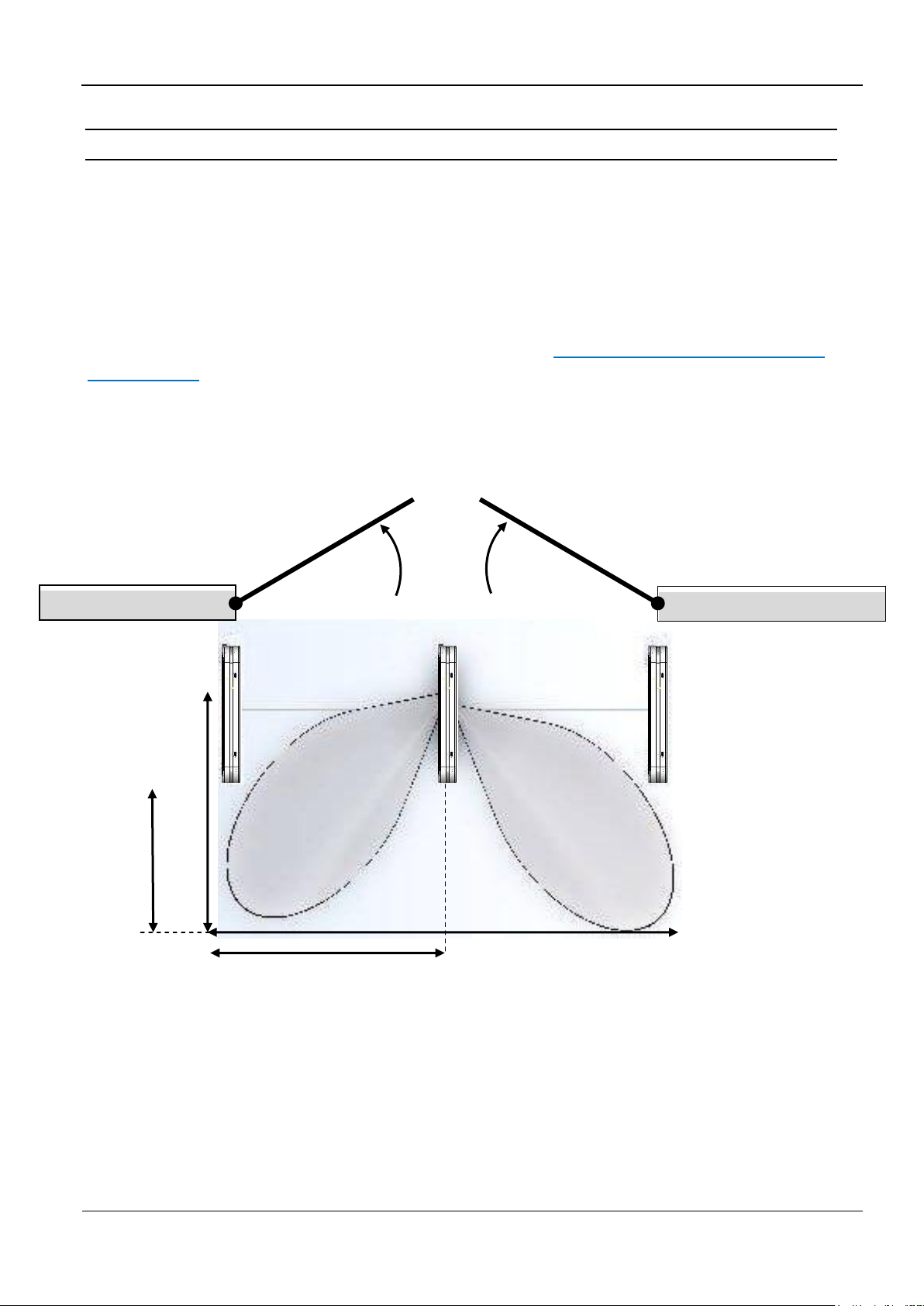
5.2 Project Notes People Counter (GPC)
The radar sensor of the People Counter detect moving objects within the detection area / beam
(A1, A2, see Fig. 12) of the radar antenna. The size of the detection area, and hence the sensitivity
of the devices can be adjusted with jumpers JP1 and JP2
A door (including glass doors), a curtain and in particular automatic doors or other moving objects
can influence the counting of the People Counter much.
If a People Counter is installed in the antenna, the antenna conductors in the middle of the antenna
body must be aligned, that the red arrows show, according to Fig. 8 Transverse conductors facing
same direction in the direction of free space.
That means, the antennas are installed close to the entrance and exit, the detection area of the
radar sensors must show away from the door. Otherwise, a minimum distance of 1.0 m between
moving objects and detection areas must be guaranteed.
Fig. 12: Top: Detection area A1 und A2 (Foot print) of the radar sensor

OBID i-scan®
Installation
ID ISC.ANT1700/740-A /-B
FEIG ELECTRONIC GmbH
Page 23 of 74
M91201-5e-ID-B.doc
Sensitivity
Low:
JP1+2 open
Medium:
JP1 closed
**
High:
JP2 closed
Very high:
JP1+2 closed
Distance A
180 cm
200 cm
200 – 220 cm
240 - 260 cm
Distance B
100–110 cm
110 cm
120 cm
160 cm
Distance C
40-50 cm
50 cm
80 cm
100 cm
Distance D
90 cm
100 cm
100 – 110 cm
120 - 130 cm
Table 6: Detection area radar sensor, antenna distance 1m
**
Standard configuration
All values are approximate, depending on the size of the objects, the behavioral reflection of the
floor and the material of the moving object.
If two people (or moving objects) move, simultaneously, in the detection area of one radar sensor,
usually, is counted one person, only.
The minimum distance between two people, so that these people are detected separately, as a
function of the adjusted sensitivity and position in the passage is 60 cm to 130 cm.
Cross traffic in the detection area, i.e. people who cross in front of the antennas, go from left to
right (or contrariwise), can also be counted or recorded.
To avoid interference, the detection area of radar motion detector, mounted above or at automatic
doors (Operating frequency 24.125 GHz), must not overlap with the detection area People
Counter.
The People Counter was designed to obtain statistical values on visitor flows. By people
with small distances, due to interferences, and by cross traffic, can vary the determined
values of the actual values.
If greater deviations are found, at first, the sensitivity of the radar sensors should be reduced
stepwise.
 Loading...