

Feig Electronic OBID i-scan ID ISC.ANT.PS-A, OBID i-scan ID ISC.ANT.T-A Mounting Instructions
Page 1
OBID
Montageanleitung / Mounting instructions
i
-scan
ID ISC.ANT.PS-A
Power Splitter for i-dist
ID ISC.ANT.T-A
Transformer for i-dist
(deutsch / english)
M01101-1de-ID-B.DOC
Page 2

Identifikation System OBID
i-scan
Lieferumfang:
• 1 Stück Power Splitter ID ISC.ANT.PS-A oder Transformer ID ISC.ANT.T-A
• 1 Stück Antennenanschlußkabel mit 2 SMA Stecker 3,62 m oder 7,20 m lang
D E U T S C H
• Montageanleitung
Copyright 2001 by FEIG ELECTRONIC GmbH
Lange Straße 4
D-35781 Weilburg-Waldhausen
http://www.feig.de
Ausgabe: wm/01/05/03 - m01101-1de-id-b.doc
Alle früheren Ausgaben verlieren mit diesem Handbuch ihre Gültigkeit. Die Angaben in diesem Handbuch können ohne
vorherige Ankündigung geändert werden.
Weitergabe sowie Vervielfältigung dieses Dokuments, Verwertung und Mitteilung ihres Inhalts sind nicht gestattet, so-
weit nicht ausdrücklich zugestanden. Zuwiderhandlung verpflichtet zu Schadenersatz. Alle Rechte für den Fall der Patenterteilung oder Gebrauchsmuster-Eintragung vorbehalten.
Die Zusammenstellung der Informationen in diesem Handbuch erfolgt nach bestem Wissen und Gewissen. FEIG
ELECTRONIC GmbH übernimmt keine Gewährleistung für die Richtigkeit und Vollständigkeit der Angaben in diesem
Handbuch. Insbesondere kann FEIG ELECTRONIC GmbH nicht für Folgeschäden aufgrund fehlerhafter oder unvollständiger Angaben haftbar gemacht werden. Da sich Fehler, trotz aller Bemühungen nie vollständig vermeiden lassen,
sind wir für Hinweise jederzeit dankbar.
Die in diesem Handbuch gemachten Installationsempfehlungen gehen von günstigsten Rahmenbedingungen aus. FEIG
ELECTRONIC GmbH übernimmt keine Gewähr für die einwandfreie Funktion einer OBID®-Anlage in systemfremden
Umgebungen.
FEIG ELECTRONIC GmbH übernimmt keine Gewährleistung dafür, daß die in diesem Dokument enthaltenden Informa-
tionen frei von fremden Schutzrechten sind. FEIG ELECTRONIC GmbH erteilt mit diesem Dokument keine Lizenzen auf
eigene oder fremde Patente oder andere Schutzrechte.
OBID® ist ein eingetragenes Warenzeichen der FEIG ELECTRONIC GmbH.
Seite 2 von 28 FEIG ELECTRONIC GmbH
Page 3

Montageanleitung ID ISC.ANT.PS-A, ID ISC.ANT.T-A
deutsche Version ab Seite 2
english version from page 16
D E U T S C H
E N G L I S H
FEIG ELECTRONIC GmbH Seite 3 von 28
Page 4

Identifikation System OBID
i-scan
Inhalt:
Inhalt:..................................................................................................................................4
D E U T S C H
1. Sicherheits- und Warnhinweise...................................................................................5
2. Das Funktionsprinzip des OBID® i-
scan
-Systems......................................................6
3. Leistungsmerkmale der Geräte ID ISC.ANT.PS-A und ID ISC.ANT.T-A....................6
4. Montage und Anschluß.................................................................................................7
5. Inbetriebnahme ...........................................................................................................10
5.1. Inbetriebnahme ID ISC.ANT.PS-A...................................................................................10
5.2. Inbetriebnahme ID ISC.ANT.T-A......................................................................................11
6. Technische Daten ID ISC.ANT.PS-A..........................................................................12
7. Technische Daten ID ISC.ANT.T-A.............................................................................14
Seite 4 von 28 FEIG ELECTRONIC GmbH
Page 5

1. Sicherheits- und Warnhinweise
Montageanleitung ID ISC.ANT.PS-A, ID ISC.ANT.T-A
Vor Inbetriebnahme unbedingt beachten !
• Das Gerät darf nur für den vom Hersteller vorgesehenen Zweck verwendet werden.
• Die Montageanleitung ist zugriff s fähig aufzubewahren und jedem Instandhalter und Benut zer
auszuhändigen.
• Unzulässige Veränderungen und die Verwendung von Ersatzteilen und Zusatzeinrichtungen,
die nicht vom Hersteller des Gerätes verkauft oder empfohlen werden, können Brände, elektrische Schläge und Verletzungen verursachen. Solche Maßnahmen führen daher zu einem
Ausschluß der Haftung und der Hersteller übernimmt keine Gewährleistung .
• Für das Gerät gelten die Gewährleistungsbest im m ungen des Herstellers in der zum Zeitpunkt
des Kaufs gültigen Fassung. Für eine ungeeignete, falsche manuelle oder aut om atische Einstellung von Parametern für ein G er ät bzw. ungeeignete Verwendung eines Gerätes wird keine
Haftung übernommen.
• Reparaturen dürfen nur vom Hersteller dur chgeführt werden.
• Anschluß-, Inbetriebnahme-, Wartungs-, Messungs- und Einst ellungsarbeiten am Gerät dürf en
nur von Elektrofachkräften mit einschlägiger Unfallverhütungsausbildung erfolgen.
D E U T S C H
• Beim Umgang mit Geräten, die mit elektrischer Spannung in Berührung kommen, müssen die
jeweils gültigen Sicherheitsvorschrift en beacht et werden.
• Vor dem Öffnen des Ger ät es ist stets die Versorgungsspannung des Reader abzuschalten
und durch Nachmessen sicherzustellen, daß das Gerät spannungslos ist .
• Beim Arbeiten am geöff neten Gerät ist zu beachten, daß Spannungen bis zu 1000V an den
Bauteilen anliegen können.
• Alle Arbeiten am Gerät und dessen Aufstellung müssen in Übereinstimmung mit den nationalen elektrischen Bestimmungen und den ör t lichen Vor schriften durchgeführt werden.
• Das Gerät ist nach den anerkannten technischen Regeln im Aufstellungsland sowie anderen
regionalen gültigen Vorschriften aufzustellen und anzuschließen.
FEIG ELECTRONIC GmbH Seite 5 von 28
Page 6

Identifikation System OBID
i-scan
2. Das Funktionsprinzip des OBID® i-
Das Identifikationssystem OBID® i-
scan
-Systems
scan
ist ein induktives Übertragungssystem zur
berührungslosen Identifik ation (ID) von bewegten Objekten. Mit den Komponenten des Schreib- /
D E U T S C H
Lesesystems ist ein Beschreiben und Lesen von passiven Datenträgern (Transponder), mit einer
Arbeitsfrequenz von 13.56 MHz, sogenannten „Smart Label“, möglich. Es besteht aus den
Komponenten Reader ID ISCLRxxx-x, einer oder mehreren Antennen und einem oder mehreren
Smart Labeln als Speichermedium f ür die Dat en.
Diese Smart Label sind i.d.R. Papieret iketten, in denen ein hauchdünner Transponder eingef aßt
ist und die somit mit RFID Schreib-/Leseg er ät en kommunizieren können.
Gelangt ein Smart Label in das lok ale Magnetfeld der Antenne, wird er mit Energie versor gt und
kann gelesen und beschrieben werden. Die empfangenen Daten werden von der gleichen
Antenne des
Readers
empfangen, die auch das Magnetfeld erzeugt und die Daten zum
Datenträger sendet.
Das Magnetfeld und die gesendeten und empfangenen Daten vom Datenträger können nahezu
alle, nichtleitenden Materialien durchdringen, so daß auch ein verdecktes Schreiben und Lesen
möglich ist.
Die Anticollision-Funktion des Readers ermöglicht das gleichzeitige Lesen von bis zu 50 Smart
Label pro Sekunde.
3. Leistungsmerkmale der Geräte ID ISC.ANT.PS-A und ID ISC.ANT.T-A
Das Gerät ID ISC.ANT.T-A ist ein 1:1 Übertrager mit galvanischer Trennung .
Das Gerät hat bei der Betriebsf requenz von 13.56 MHz eine Eingangs- und Ausgangsimpedanz
von 50 Ω mit Kompensation des Phasenwinkels zwischen Strom und Spannung.
Durch die galvanische Trennung zwischen Reader und Antenne können Störungen, welche be-
sonders in industriellen Umgebungen auftreten, nahezu ohne Beeinträchtigung der Nutzsignale
unterdrückt werden.
Das Gerät ID ISC.ANT. PS-A ist ein 3 dB Leistungsteiler (Power Splitter) mit galvanischer Trennung zwischen Eingang und den 2 Ausgängen. Bei der Betriebsfrequenz von 13.56 MHz ist die
Impedanz an allen Ein- und Ausgängen auf 50 Ω abgeglichen.
Beide Ausgänge sind intern in Reihe verschaltet. Die galvanische Trennung kann mit Hilfe von 2
Brücken (Jumpern) überbrückt werden.
Beide Geräte sind für die Montage im Innen- wie auch den Außenbereich k onzipiert . Die Anschlußkabel vom Reader zum Gerät ID ISC.ANT.T-A ist 7,20 m lang und zwischen Reader und
Gerät ID ISC.ANT. PS-A ist 3,6 m lang. Damit verläng er t sich die gesamte Kabellänge vom Reader
zur Antenne auf insgesamt 10,82 m bzw. 7,20 m.
Seite 6 von 28 FEIG ELECTRONIC GmbH
Page 7
Montageanleitung ID ISC.ANT.PS-A, ID ISC.ANT.T-A
4. Montage und Anschluß
Die Geräte ID ISC.ANT. PS-A und ID ISC.ANT.T -A sind für die Montage auf nicht leitenden Materialien (z.B. Kunststoff oder Holz) sowohl für den Innen- wie auch den Außenbereich konzipiert.
Zur Montage befinden sich im Innenbereich der Gehäuse 4 Bohr ungen (d=5,0 mm) im Abstand
von 79 mm.
Eine Montage direkt auf Metall, sollte vermieden werden ! Andernf alls ist mit Leistungseinbußen
zu rechnen.
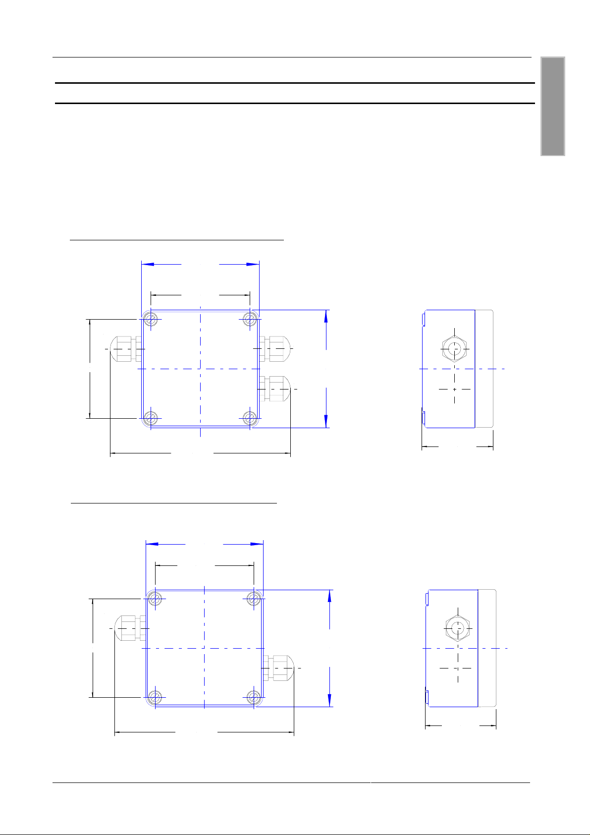
Bild 1: Montagezeichnung ID ISC.ANT.PS- A
94,00 mm
79,00 mm
M16
M16
D E U T S C H
79,00 mm
144,00 mm
Bild 2: Montagezeichnung ID ISC.ANT.T-A
94,00 mm
79,00 mm
M16
79,00 mm
M16
M16
94,00 mm
57,00 mm
94,00 mm
144,00 mm
57,00 mm
FEIG ELECTRONIC GmbH Seite 7 von 28
Page 8
Identifikation System OBID
i-scan
Vor dem Anschluß der Koaxialkabel sollte die Platine aus dem Gehäuse genommen werden. Dann
die Kabel durch die Kabelverschraubungen gesteckt und an den SMA-Buchsen angeschraubt
werden. Anschließend muß die Platine wieder in das Gehäuse montiert und die Kabelverschraubungen angezogen werden. Dabei muß das Koaxialkabel wieder bis auf die notwendige Länge
zwischen Buchse und Kabelverschraubung herausgezogen werden.
D E U T S C H
Tabelle 1 : Buchsenbelegung der Platine
Klemme ID ISC.ANT.PS-A ID ISC.ANT.T-A
X1 Anschluß der Basisantenne 1
Anschluß der Basisantenne
oder Ergänzungsantenne 1
X2 Anschluß der Basisantenne 2
Frei
oder Ergänzungsantenne 2
X3 Anschlußkabel vom Reader Anschlußkabel vom Reader
Achtung: maximales Anzugsdrehmoment für die SMA-Stecker ist 0,45Nm
Die Geräte ID ISC.ANT. PS-A und ID ISC.ANT.T-A werden mit Hilfe des mitgelieferten Anschlußkabels direkt mit dem Reader ( Buchse X 1) und der Platine (Buchse X3) angeschlossen.
Die Antennenkabel werden laut Tabelle 1 und der Schaltsk izzen Bild 3 und Bild 4 mit den Antennen verbunden.
Um mögliche Störungen zu unt erdrücken, werden dem Reader ID ISC.LRxxxx 2 Ringk erne beigelegt. Diese sollten in die Antennenanschlußkabel des Power Splitter oder Transformer eingebaut werden. Dafür muß das Anschlußkabel 4 mal durch den Kern gezogen werden damit das
Kabel möglichst nahe am Kern anliegt .
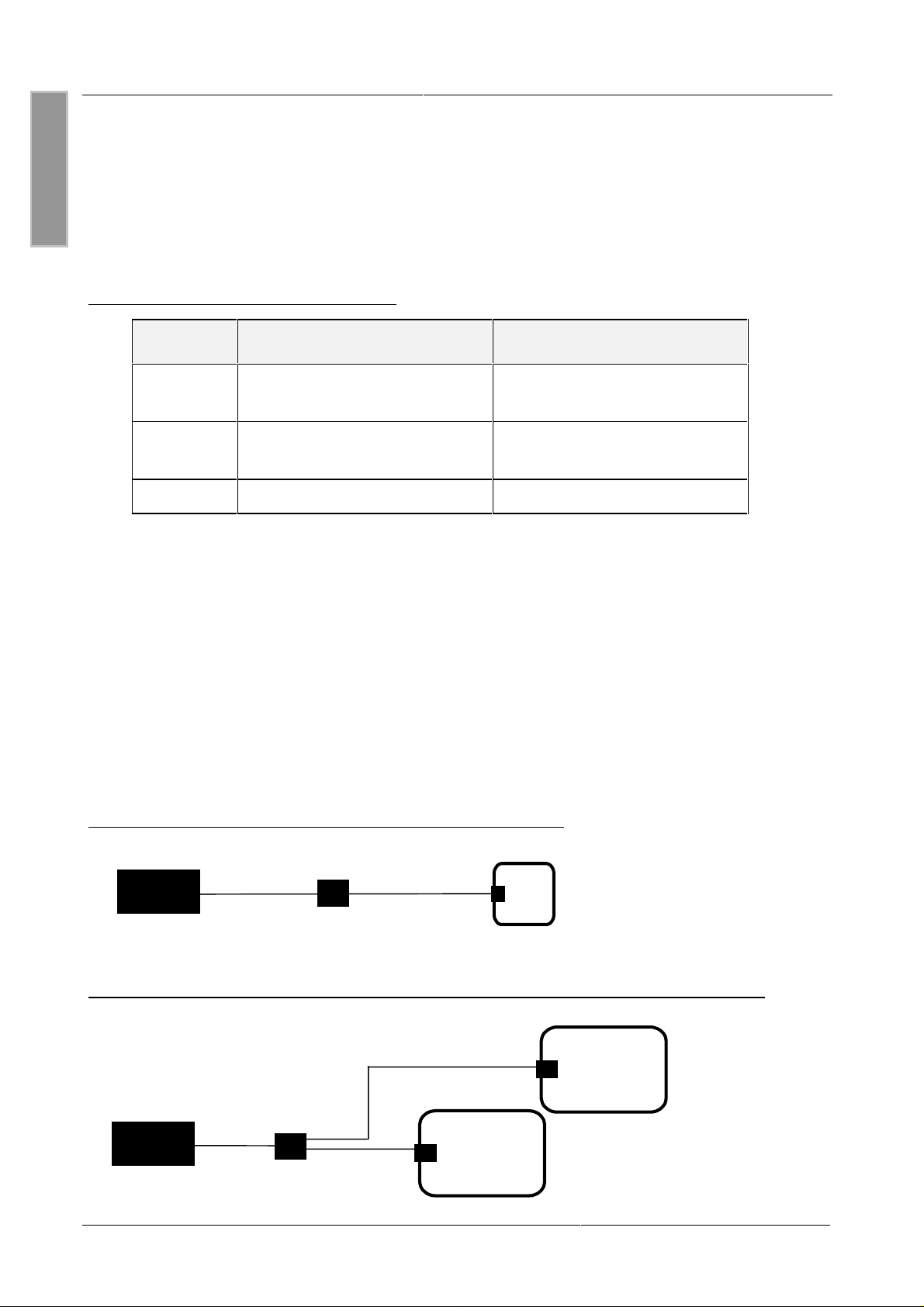
Bild 3: Schaltskizze Reader mit Transfor m er und Basisantenne
ID ISC.ANTx00/x00-A
Reader
ID ISC.ANT.T
Bild 4: Schaltskizze: Ein Reader und zwei Basisantennen oder zwei Ergänzungsantennen
ID ISC.ANTx00/x00-x
ID ISC.ANTx00/x00-x
Reader
Seite 8 von 28 FEIG ELECTRONIC GmbH
ID ISC.ANT.PS
Page 9

Montageanleitung ID ISC.ANT.PS-A, ID ISC.ANT.T-A
λ
Die folgenden Empfehlungen sollten zusätzlich beachtet werden:
• Um optimale Lesereichweiten zu erzielen sollte das Antennenanschlußkabel nicht verkürzt
oder verlängert werden. Ist eine Verlängerung zwingend erforderlich, so kann dies mit einem 50
Ω Kabel in der Länge
werden. Dabei ist mit geringen Empf indlichkeitsverlusten zu rechnen.
• Das Antennenkabel muß einen Mindestabstand von 30 cm zu parallel geführten, stromführen-
den Leitungen haben.
(halbe Wellenlänge bei 13,56 MHz, RG58=7,20 m) durchgeführt
2
D E U T S C H
FEIG ELECTRONIC GmbH Seite 9 von 28
Page 10
Identifikation System OBID
5. Inbetriebnahme
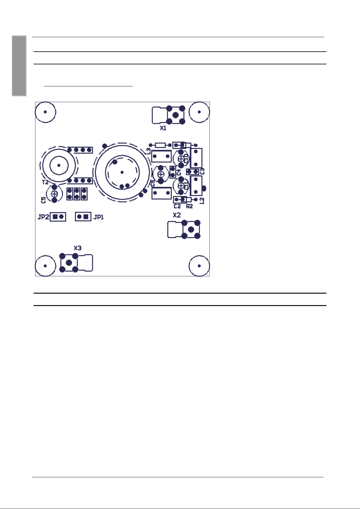
Bild 5: Draufsicht : Leiterplatte
D E U T S C H
i-scan
5.1. Inbetriebnahme ID ISC.ANT.PS-A
Vor dem Einbau der Power Splitter müssen beide Antennen abgeglichen sein. Dafür werden die
Antennen oder Gates direkt mit dem Reader verbunden. Anschließend wird jeweils immer eine
Basis- oder eine Basis- und Ergänzungsantenne (Gat e) einzeln abg eglichen.
Sind alle Antennen abgeglichen, können die Power Splitt e r eingebaut werden.
Das Gerät ID ISC.ANT. PS-A wurde im Werk eingestellt und ist nach dem Einbau sof o r t bet riebs-
fertig. Um Kopplung seffekte auszugleichen kann nach der Montag e des Power Splitt er ein Feinabgleich (siehe Montageanleitung Antenne) notwendig werden.
Werden mit dem Gerät ID ISC.ANT.PS-A zwei Ergänzungsantennen angeschlossen, so kann
durch Brücken der Jumpern JP1 und JP2 die galvanische Tr ennung zwischen Reader und Antennen überbrückt werden. Dies vermindert die Signalverluste um ca. 1-2 dB.
Seite 10 von 28 FEIG ELECTRONIC GmbH
Page 11

Montageanleitung ID ISC.ANT.PS-A, ID ISC.ANT.T-A
5.2. Inbetriebnahme ID ISC.ANT.T-A
Vor dem Einbau des Transformer s I D I SC. ANT.T-A muß die Antenne oder das Gate ber eits abgeglichen sein. Das Gerät ID ISC. ANT.T-A wurde im Werk eingestellt und ist nach dem Einbau zwischen Reader und Antennenkabel sofort bet r iebsfertig.
D E U T S C H
FEIG ELECTRONIC GmbH Seite 11 von 28
Page 12

Identifikation System OBID
i-scan
6. Technische Daten ID ISC.ANT.PS-A
D E U T S C H
Mechanische Daten
Elektrische Daten
• Gehäuse
• Abmessungen ( B x H x T )
• Gewicht
• Schutzart
• Farbe
• Maximale Eingangsleistung
• Betriebsfrequenz
Kunststoff Polycarbonat
94 x 94 x 57 mm
0,3 kg
IP 65
Hellgrau
10 W
13.56 MHz
• Impedanz 50 Ω ± 6 Ω
• Phase 0 ° ± 6°
• Eingangsverluste
• Anschluß
– Buchsen
– Anschlußkabel
Umgebungsbedingungen
• Temperaturbereich
– Betrieb
– Lagerung
• Vibration
• Schock
–25°C bis +65°C
–25°C bis +80°C
EN60068-2-6
10 Hz bis 150 Hz : 0,075 mm / 1 g
EN60068-2-27
Beschleunigung : 30 g
Ca. 1 dB °
2 x SMA
RG58, 3,6 m lang
Seite 12 von 28 FEIG ELECTRONIC GmbH
Page 13

Angewendete Normen
Montageanleitung ID ISC.ANT.PS-A, ID ISC.ANT.T-A
• EMV
• Sicherheit
– Europa
– USA
EN 300 683
EN 60950
UL 1950 (Auf Anfrage)
D E U T S C H
FEIG ELECTRONIC GmbH Seite 13 von 28
Page 14

Identifikation System OBID
i-scan
7. Technische Daten ID ISC.ANT.T-A
D E U T S C H
Mechanische Daten
Elektrische Daten
• Gehäuse
• Abmessungen ( B x H x T )
• Gewicht
• Schutzart
• Farbe
• Maximale Eingangsleistung
• Betriebsfrequenz
Kunststoff Polycarbonat
94 x 94 x 57 mm
0,3 kg
IP 65
Hellgrau
10 W
13.56 MHz
• Impedanz 50 Ω ± 6 Ω
• Phase 0 ° ± 6°
• Eingangsverluste
• Anschluß
– Buchsen
– Anschlußkabel
Umgebungsbedingungen
• Temperaturbereich
– Betrieb
– Lagerung
• Vibration
–25°C bis +65°C
–25°C bis +80°C
EN60068-2-6
10 Hz bis 150 Hz : 0,075 mm / 1 g
Ca. 1 dB °
2 x SMA
RG58, 7,2 m lang
Seite 14 von 28 FEIG ELECTRONIC GmbH
Page 15

Angewendete Normen
Montageanleitung ID ISC.ANT.PS-A, ID ISC.ANT.T-A
• EMV
• Sicherheit
– Europa
– USA
EN 300 683
EN 60950
UL 1950 (Auf Anfrage)
D E U T S C H
FEIG ELECTRONIC GmbH Seite 15 von 28
Page 16

Identifikation System OBID
i-scan
Included:
• Qty. 1 Power Splitter ID ISC.ANT.PS-A or Transformer ID ISC.ANT.T-A
• Qty.1 antenna connector cable with 2 SMA connectors 3.62m or 7.20 m.
• This document
E N G L I S H
Copyright 2001 by FEIG ELECTRONIC GmbH
Lange Straße 4
D-35781 Weilburg-Waldhausen
http://www.feig.de
Edition: wm/01/05/03 - m01101-1de-id-b.doc
Copying of this document, and giving it to others and the use or communication of the contents thereof are
forbidden without express authority. Offenders are liable to the payment of damages. All rights are reserved in
the event of the grant of a patent or the registration of a utility model or design.
Indications made in this manual may be changed without previous notice. With the edition of this manual, all previous
editions become void.
Composition of the information in this manual has been done to the best of our knowledge. FEIG ELECTRONIC GmbH
does not guarantee the correctness and completeness of the details given in this manual and may not be held liable for
damages ensuing from incorrect or incomplete information. Since, despite all our efforts, errors may not be completely
avoided, we are always grateful for your useful tips.
The installation instructions given in this manual are based on advantageous boundary conditions. FEIG ELECTRONIC
GmbH does not give any guarantee promise for perfect function of an OBID®-system in cross surroundings.
FEIG ELECTRONIC GmbH assumes no responsibility for the use of any information contained in this manual and
makes no representation that they free of patent infringement. FEIG ELECTRONIC GmbH does not convey any license
under its patent rights nor the rights of others.
OBID® is a registered trademark of FEIG ELECTRONIC GmbH.
Page 16 of 28 FEIG ELECTRONIC GmbH
Page 17

Mounting Instructions ID ISC.ANT.PS-A, ID ISC.ANT.T-A
Contents:
Contents: ..........................................................................................................................17
8. Safety instructions......................................................................................................18
9. Functional description of the OBID® i-
scan
-system ................................................19
10. Performance features for the ID ISC.ANT.PS-A and ID ISC.ANT.T-A....................19
11. Assembly and wiring ................................................................................................20
12. Startup .......................................................................................................................23
12.1. Startup: ID ISC.ANT.PS-A..............................................................................................23
12.2. Startup: ID ISC.ANT.T-A................................................................................................24
13. Technical Data for ID ISC.ANT.PS-A........................................................................25
14. Technical Data for ID ISC.ANT.T-A..........................................................................27
E N G L I S H
FEIG ELECTRONIC GmbH Page 17 of 28
Page 18

Identifikation System OBID
i-scan
8. Safety instructions
Please read before startup !
• The appliance should only be used for the purpose intended by the manuf act ur er .
• The mounting instructions should be handed out t o every user and kept in an easily accessible
place.
• Improper changes as well as the use of spare part s and special features that are not sold or
E N G L I S H
recommended by the manufacturer m ay cause fire, electric shocks and injuries. Such m easures do therefore lead to a nonliability of the manufacturer.
• The appliance is subject to the manuf act urer’s guarantee regulations valid at the tim e of pur-
chase. We cannot be held liable for improper or wrong manual or autom atic adjustment of parameters response improper use of an appliance.
• Repair work should only be carried out by the manufacturer.
• Connection, initiation, maintenance, measuring and adjustment of the appliance should only be
carried out by qualified electricians having a g ood knowledge of the rules for the pr evention of
accidents.
• Please observe the valid safet y regulat ions when handling appliances which get in contact with
electric current.
• Please switch off the current supply of t he r eader and make sure that it is idle bef or e opening
the appliance.
• When working on the open appliance, please keep in mind that there may be voltages of up to
1000V at the various components.
• All labour carried out at the appliance as well as its installation has to be carried out in strict
compliance with the national and local electric regulations.
• The appliance has to be installed and connected according to the t echnical regulations of the
country of installation as well as other regional directions.
Page 18 of 28 FEIG ELECTRONIC GmbH
Page 19

Mounting Instructions ID ISC.ANT.PS-A, ID ISC.ANT.T-A
9. Functional description of the OBID® i-
The identification system OBID® i-
identification (ID) of moving object s. The com ponents of t he write/read system f acilitate the writing
and reading of passive data carriers (T ransponder ) with an actual f req uency of 13.56 MHz, the so-
called „smart labels“. It consist s of a reader ID ISCLRxxx-x, one or several antennas and one or
more smart labels used as a data storag e m edium .
These smart labels are generally paper badg es or t ags with a wafer-thin transponder integr at ed for
communicating with RFID read/write devices.
If a smart label get s into the antenna’s local magnetic field, it is powered and may be read and
written. Data is received by the same reader antenna that also pr oduces the magnetic field and
sends the data to the data carrier.
The magnetic field and all data sent and received by the data carrier are able to penetrat e almost
all non-conductive materials, so that even hidden writing and reading is possible.
The reader’s anticollision function f acilitates the simult aneous reading of up to 50 smart labels per
second.
scan
scan
-system
is an inductive transmission system for touchless
E N G L I S H
10. Performance features for the ID ISC.ANT.PS-A and ID ISC.ANT.T-A
The ID ISC.ANT.T -A is a 1:1 transformer with g a lvanic isolation.
At an operating frequency of 13.56 MHz the device has an input and output impedance of 50 Ω
with phase angle compensation between current and voltage.
The galvanic isolation between Reader and antenna ensures that noise which can occur especially
in industrial environments is effect ively suppressed without comprom ising the payload signals.
The ID ISC.ANT.PS-A is a 3 dB power split t er with galvanic isolation between the input and the 2
outputs. At an operating frequency of 13.56 MHz the impedance is balanced to 50 Ω on all in- and
outputs.
Both outputs are internally wired in series. The galvanic isolation may be bridged using two
jumpers.
Both units are suitable for indoor or outdoor installation. The connector cables Reader and unit ID
ISC.ANT.T is 7.2 m long and between Reader and unit ID ISC.ANT.PS is 3.6 m long. Therefor e
extend the antenna connector cable from t he Reader t o the antenna to a total of 10.8 m r espectively 7.20 m.
FEIG ELECTRONIC GmbH Page 19 of 28
Page 20

Identifikation System OBID
i-scan
11. Assembly and wiring
The ID ISC.ANT.PS-A and I D ISC.ANT .T -A are desig ned to be mounted on non-conduct ing materials (e.g. plastic or wood) and are suitable f or indoor or out door use. Four smooth mount ing holes
(d=5.0 mm) with 79 mm spacing are located inside the housing .
Do not attach the devices directly to metal ! Ot her wise power losses will result.
Figure 6: Assembly drawing ID ISC.ANT.PS-A
94,00 mm
E N G L I S H
M16
79,00 mm
Figure 7: Assembly drawing ID ISC.ANT.T-A
79,00 mm
144,00 mm
94,00 mm
79,00 mm
M16
M16
94,00 mm
57,00 mm
M16
79,00 mm
M16
144,00 mm
94,00 mm
57,00 mm
Page 20 of 28 FEIG ELECTRONIC GmbH
Page 21

Mounting Instructions ID ISC.ANT.PS-A, ID ISC.ANT.T-A
Remove the circuit board from t he housing bef or e att aching t he coaxial cable. T hen f eed the cable
through the cable fittings and fasten to the SMA sockets. Then mount the circuit board in the
housing and fasten the cable –glands.
Table 2 : Board socket f unct ions
Terminal ID ISC.ANT.PS-A ID ISC.ANT.T-A
X1 Connects base antenna 1 or
complementary antenna 1
X2 Connects base antenna 2 or
complementary antenna 2
X3 Connector cable from Reader Connector cable from Reader
Caution: Maximum tightening t orque f or the SMA plugs is 0.45 Nm
The ID ISC.ANT.PS-A and ID ISC.ANT.T-A are connected directly to the Reader (Terminal X1)
and the circuit board (Terminal X 3) using the connector cable supplied.
The antenna cables are connected to the antennas as shown in Tabelle 1 and the wiring diag rams
Figure 8 and Figure 9.
Two ring cores are supplied with the ID ISC.LRxxxx Reader for suppressing any pos sible noise.
These should be installed in the antenna connector cable f or the power splitter or t ransformer. To
do this feed Cable 4 through the cor e so t hat the cable is located as close as possible to the core.
Figure 8: Wiring diagram for Reader with transformer and basic antenna
Connects basic antenna
Not used
E N G L I S H
ID ISC.ANTx00/x00-A
Reader
Figure 9: Wiring diagram: One Reader and t wo basic antennas or two complementary antennas
Reader
FEIG ELECTRONIC GmbH Page 21 of 28
ID ISC.ANT.T
ID ISC.ANTx00/x00-x
ID ISC.ANTx00/x00-x
ID ISC.ANT.PS
Page 22

Identifikation System OBID
λ
Please note also the following recommendations:
• To achieve optimal read distances the antenna connector cable should not be shortened or
lengthened. If it is absolut ely necessary to lengt hen t he cable, do t his using a 50 Ω cable with a
i-scan
length
will result.
• The antenna cable must be kept a minimum of 30 cm from parallel routed power cables.
(half a wavelength at 13.56 MHz, RG58=7.20 m). Note that a slight loss in sensitivity
2
E N G L I S H
Page 22 of 28 FEIG ELECTRONIC GmbH
Page 23

12. Startup
Figure 10: Circuit board: Top view
Mounting Instructions ID ISC.ANT.PS-A, ID ISC.ANT.T-A
E N G L I S H
12.1. Startup: ID ISC.ANT.PS-A
Before installing the power splitter you must first tune both antennas. For t his t he antennas or
gates are connected directly to the Reader. Next t une each basic or basic/ c om plem entary antenna
combination (gate) individually.
Once all the antennas are tuned you may install the power splitters.
Each ID ISC.ANT.PS-A was factory tuned and is r eady to use as soon as it is inst alled. To com-
pensate for coupling effects the power splitter may require fine adjustment (see Assembly Guide
for antenna).
If two complementary antennas are connected t o t he I D I SC. ANT.PS-A you may use Jumpers JP1
and JP2 to bridge the galvanic isolation between the Reader and the ant ennas. This reduces the
signal losses by approx. 1-2 dB..
FEIG ELECTRONIC GmbH Page 23 of 28
Page 24

Identifikation System OBID
i-scan
12.2. Startup: ID ISC.ANT.T-A
Before installing the ID ISC. ANT.T-A Transformer you must have already calibrated the antenna or
gate. The ID ISC.ANT . T-A was factory calibrated and is ready to use.
E N G L I S H
Page 24 of 28 FEIG ELECTRONIC GmbH
Page 25

Mounting Instructions ID ISC.ANT.PS-A, ID ISC.ANT.T-A
13. Technical Data for ID ISC.ANT.PS-A
Mechanical Data
• Housing
• Dimensions (w x h x d)
• Weight
• Enclosure rating
• Color
Plastic (polycarbonate)
94 x 94 x 57 mm
0.3 kg
IP 65
light gray
Electrical Data
• Max. input power
• Operating frequency
• Impedance 50 Ω ± 6 Ω
• Phase 0 ° ± 6°
10 W
13.56 MHz
E N G L I S H
• Input losses
• Connection
– Sockets
– Connector cable
Ambient Conditions
• Temperature range
– Operating
– Storage
• Vibration
• Shock
Ca. 1 dB °
2 x SMA
RG58, 3.6 m long
–25°C to +65°C
–25°C to +80°C
EN60068-2-6
10 Hz to 150 Hz :0.075 mm / 1 g
EN60068-2-27
Acceleration : 30 g
FEIG ELECTRONIC GmbH Page 25 of 28
Page 26

Identifikation System OBID
Applicable Norms
i-scan
• EMC
• Safety
– Europe
– USA
E N G L I S H
EN 300 683
EN 60950
UL 1950 (on request)
Page 26 of 28 FEIG ELECTRONIC GmbH
Page 27

Mounting Instructions ID ISC.ANT.PS-A, ID ISC.ANT.T-A
14. Technical Data for ID ISC.ANT.T-A
Mechanical Data
• Housing
• Dimensions (w x h x d)
• Weight
• Enclosure rating
• Color
Plastic (polycarbonate)
94 x 94 x 57 mm
0.3 kg
IP 65
Light gray
Electrical Data
• Max. input power
• Operating frequency
• Impedance 50 Ω ± 6 Ω
• Phase 0 ° ± 6°
10 W
13.56 MHz
E N G L I S H
• Input losses
• Connection
– Sockets
– Connector cable
Ambient Conditions
• Temperature range
– Operating
– Storage
• Vibration
Ca. 1 dB °
2 x SMA
RG58, 7.2 m long
–25°C to +65°C
–25°C to +80°C
EN60068-2-6
10 Hz to 150 Hz :0.075 mm / 1 g
FEIG ELECTRONIC GmbH Page 27 of 28
Page 28

Identifikation System OBID
Applicable Norms
i-scan
• EMC
• Safety
– Europe
– USA
E N G L I S H
EN 300 683
EN 60950
UL 1950 (on request)
Page 28 of 28 FEIG ELECTRONIC GmbH
 Loading...