

Page 1
MONTAGE
INSTALLATION
final
ID ISC.ANT.UMUX-A
UHF Antenna Multiplexer
public (B)
2012-03-09
M71100-2de-ID-B.doc
(deutsch / english)
Page 2

OBID i-scan® Montage ID ISC.ANT.UMUX
D E U T S C H
E N G L I S H
deutsche Version ab Seite 3
english version from page 17
FEIG ELECTRONIC GmbH Seite 2 von 30 M71100-2de-ID-B.doc
Page 3

OBID i-scan® Montage ID ISC.ANT.UMUX
D E U T S C H
Hinweis
Copyright 2008 by
FEIG ELECTRONIC GmbH
Lange Straße 4
D-35781 Weilburg-Waldhausen
Tel.: +49 6471 3109-0
http://www.feig.de
Alle früheren Ausgaben verlieren mit dieser Ausgabe ihre Gültigkeit.
Die Angaben in diesem Dokument können ohne vorherige Ankündigung geändert werden.
Weitergabe sowie Vervielfältigung dieses Dokuments, Verwertung und Mitteilung ihres Inhalts sind nicht
gestattet, soweit nicht ausdrücklich zugestanden. Zuwiderhandlung verpflichtet zu Schadenersatz. Alle
Rechte für den Fall der Patenterteilung oder Gebrauchsmuster-Eintragung vorbehalten.
Die Zusammenstellung der Informationen in diesem Dokument erfolgt nach bestem Wissen und Gewissen.
FEIG ELECTRONIC GmbH übernimmt keine Gewährleistung für die Richtigkeit und Vollständigkeit der Angaben in diesem Dokument. Insbesondere kann FEIG ELECTRONIC GmbH nicht für Folgeschäden auf
Grund fehlerhafter oder unvollständiger Angaben haftbar gemacht werden. Da sich Fehler, trotz aller Bemühungen nie vollständig vermeiden lassen, sind wir für Hinweise jederzeit dankbar.
Die in diesem Dokument gemachten Installationsempfehlungen gehen von günstigsten Rahmenbedingungen aus. FEIG ELECTRONIC GmbH übernimmt keine Gewähr für die einwandfreie Funktion in systemfremden Umgebungen.
FEIG ELECTRONIC GmbH übernimmt keine Gewährleistung dafür, dass die in diesem Dokument enthaltenden Informationen frei von fremden Schutzrechten sind. FEIG ELECTRONIC GmbH erteilt mit diesem
Dokument keine Lizenzen auf eigene oder fremde Patente oder andere Schutzrechte.
®
OBID
und OBID i-scan® ist ein eingetragenes Warenzeichen der FEIG ELECTRONIC GmbH
FEIG ELECTRONIC GmbH Seite 3 von 30 M71100-2de-ID-B.doc
Page 4

OBID i-scan® Montage ID ISC.ANT.UMUX
D E U T S C H
Inhalt
1 Sicherheits- und Warnhinweise - vor Inbetriebnahme unbedingt lesen 5
2 Leistungsmerkmal e d es 8-fach UHF-Antennenmultiplexers ID ISC.ANT.UMUX 6
2.1 Leistungsmerkmale .................................................................................................... 6
2.2 Lieferumfang ............................................................................................................... 6
2.3 Verfügbare Multiplexertypen ...................................................................................... 6
3 Anschluss und Montage 7
3.1 Abmessungen ............................................................................................................. 7
3.2 Anschlussklemmen und -buchsen ............................................................................ 8
3.3 Spannungsversorgung ............................................................................................... 8
3.4 IN: Readeranschluss .................................................................................................. 8
3.5 OUT1-8: Antennenanschluss ..................................................................................... 9
3.6 X2: Boot-Loader-Interface .......................................................................................... 9
4 Bedien- und Anzeigeelemente 10
4.1 LEDs .......................................................................................................................... 10
4.2 S1: DIP-Schalter ........................................................................................................ 10
4.2.1 Adresseinstellung ....................................................................................................... 10
4.2.2 DC-Einkopplung.......................................................................................................... 11
4.3 T1: Reset-Taster ........................................................................................................ 11
5 Technische Daten 12
6 Fehlerbeseitigung 14
7 Zubehör 15
7.1 Wandmontagesatz ID ISC.MS.MR/PR-A .................................................................. 15
FEIG ELECTRONIC GmbH Seite 4 von 30 M71100-2de-ID-B.doc
Page 5

OBID i-scan® Montage ID ISC.ANT.UMUX
D E U T S C H
1 Sicherheits- und Warnhinweise - vor Inbetriebnahme unbedingt lesen
• Das Gerät darf nur für den vom Hersteller vorgesehenen Zweck verwendet werden.
• Die Bedienungsanleitung ist zugriffsfähig aufzubewahren und jedem Benutzer auszuhändigen.
• Unzulässige Veränderungen und die Verwendung von Ersatzteilen und Zusatzeinrichtungen,
die nicht vom Hersteller des Gerätes verkauft oder empfohlen werden, können Brände,
elektrische Schläge und Verletzungen verursachen. Solche Maßnahmen führen daher zu
einem Ausschluss der Haftung und der Hersteller übernimmt keine Gewährleistung.
• Für das Gerät gelten die Gewährleistungsbestimmungen des Herstellers in der zum Zeitpunkt
des Kaufs gültigen Fassung. Für eine ungeeignete, falsche manuelle oder automatische
Einstellung von Parametern für ein Gerät bzw. ungeeignete Verwendung eines Gerätes wird
keine Haftung übernommen.
• Reparaturen dürfen nur vom Hersteller durchgeführt werden.
• Anschluss-, Inbetriebnahme-, Wartungs-, und sonstige Arbeiten am Gerät dürfen nur von
Elektrofachkräften mit einschlägiger Ausbildung erfolgen.
• Alle Arbeiten am Gerät und dessen Aufstellung müssen in Übereinstimmung mit den
nationalen elektrischen Bestimmungen und den örtlichen Vorschriften durchgeführt werden.
• Beim Arbeiten an dem Gerät müssen die jeweils gültigen Sicherheitsvorschriften beachtet
werden.
FEIG ELECTRONIC GmbH Seite 5 von 30 M71100-2de-ID-B.doc
Page 6

OBID i-scan® Montage ID ISC.ANT.UMUX
D E U T S C H
2 Leistungsmerkmal e d es 8-fach UHF-Antennenmultiplexers ID ISC.ANT.UMUX
2.1 Leistungsmerkmale
Der 8-fach Antennenmultiplexer ID ISC.ANT.UMUX eignet sich zum Schalten von RFID-Antennen
mit Betriebsfrequenzen von 860 – 960 MHz. Mit einem ID ISC.ANT.UMUX können mehrere Einzelantennen mit nur einem Antennenausgang eines Readers betrieben werden.
Es ist möglich, mehrere ID ISC.ANT.UMUX zu kaskadieren und so die Anzahl der möglichen Antennenanschlüsse zu erhöhen. Dazu können die Antennenmultiplexer über DIP-Schalterstellungen
adressiert werden.
2.2 Lieferumfang
Folgende Komponenten sind im Lieferumfang enthalten:
- 1 x 8-fach UHF-Antennenmultiplexer ID ISC.ANT.UMUX
- 1 x Montageanleitung
2.3 Verfügbare Multiplexertypen
Folgende Multiplexertypen sind z.Z. verfügbar:
Tabelle 1: Multiplexertypen
Multiplexertyp Beschreibung
ID ISC.ANT.UMUX-A UHF-Multiplexer in IP30 -Gehäuse
FEIG ELECTRONIC GmbH Seite 6 von 30 M71100-2de-ID-B.doc
Page 7
OBID i-scan® Montage ID ISC.ANT.UMUX
D E U T S C H
3 Anschluss und Montage
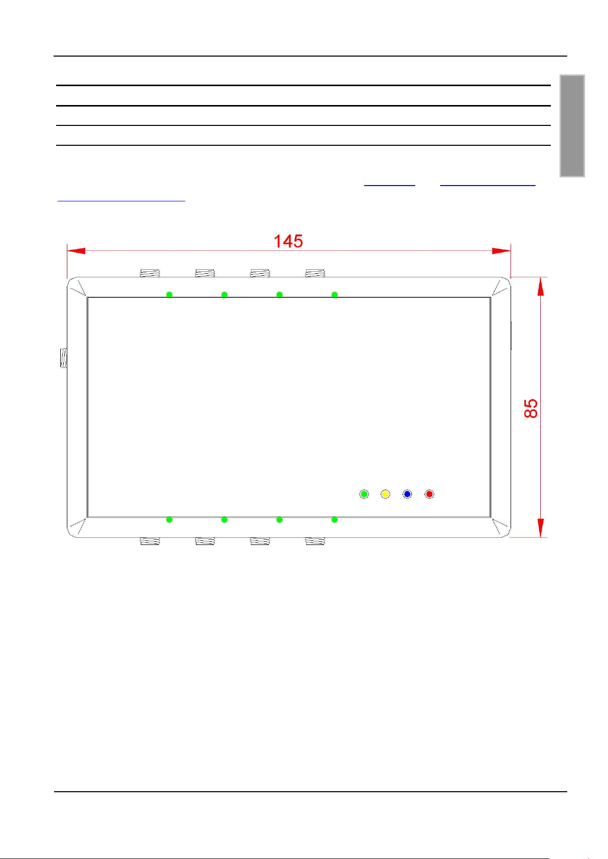
3.1 Abmessungen
Der Multiplexer ist für Anwendungen im Innenbereich konzipiert. Eine Wandmontage ist mit dem
optional erhältlichen Wandmontagesatz möglich. (Siehe Kap.
satz ID ISC.MS.MR/PR-A)
6 Zubehör und 6.1 Wandmontage-
Bild 1: Abmessungen des Gehäuses (alle Maße in mm)
FEIG ELECTRONIC GmbH Seite 7 von 30 M71100-2de-ID-B.doc
Page 8
OBID i-scan® Montage ID ISC.ANT.UMUX
D E U T S C H
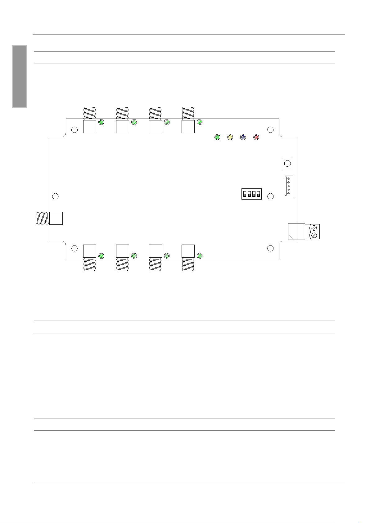
3.2 Anschlussklemmen und -buchsen
In Abbildung 2 sind alle Anschlussklemmen, Antennenbuchsen, Bedienelemente und Anzeigeteile
dargestellt.
S1
V4
X2
X1
T1
GND
VCC
OUT8 OUT7 OUT6 OUT5
V1 V2 V3
IN
OUT1 OUT2 OUT3 OUT4
Bild 2: Anschlussklemmen, Buchsen und Bedienelemente
3.3 Spannungsversorgung
Die Spannungsversorgung wird über X1 angeschlossen oder wird direkt über den
Readeranschluss IN hergestellt. Für den Anschluss an X1 ist die Polung gemäß Abbildung 2 vorzunehmen. Der UHF-Antennenmultiplexer arbeitet bei einer Gleichspannung von 12 V bis 24 V.
Beim Kaskadieren der Multiplexer besteht die Möglichkeit die verbundenen Multiplexer über das
Antennenkabel gegenseitig mit Spannung zu versorgen. Dafür muss lediglich der erste Multiplexer
hinter dem Reader über X1 an ein Netzteil angeschlossen werden.
3.4 IN: Readeranschluss
Der Anschluss an einen Reader erfolgt mit einem Antennenkabel über die SMA-Buchse IN. Das
maximale Anzugsdrehmoment der SMA-Buchse beträgt 0,45 Nm.
Die Sendeleistung am Readeranschluss IN muss mindestens 85 mW betragen.
FEIG ELECTRONIC GmbH Seite 8 von 30 M71100-2de-ID-B.doc
Page 9
OBID i-scan® Montage ID ISC.ANT.UMUX
D E U T S C H
3.5 OUT1-8: Antennenanschluss
Die Antennen bzw. weitere Multiplexer sind mit Koaxialkabel über die SMA-Buchsen OUT1-8 anzuschließen. Das maximale Anzugsdrehmoment der SMA-Buchsen beträgt 0,45 Nm.
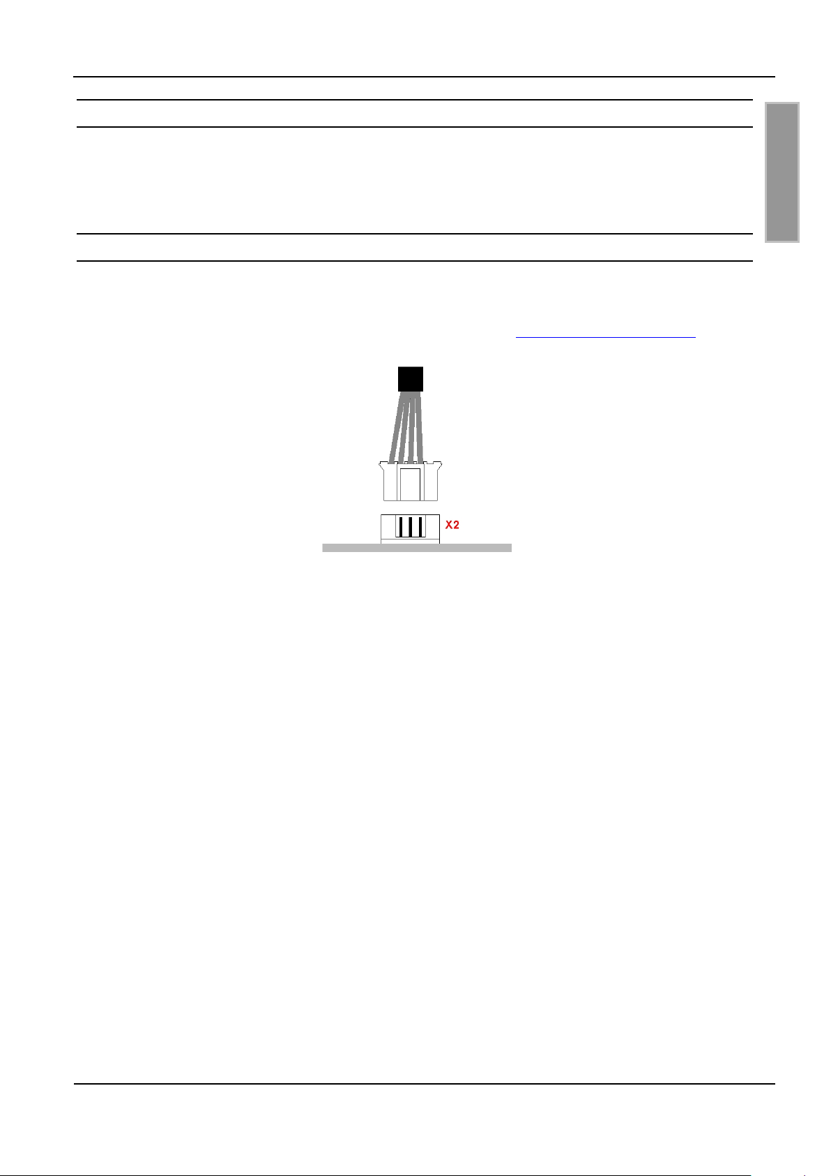
3.6 X2: Boot-Loader-Interface
Zum Durchführen eines Firmware Updates ist das Updatekabel ID CAB.RS-B auf die Stiftleiste X2
zu stecken (s. Bild 3). Die Spannungsversorgung erfolgt wie im Betrieb des Multiplexers über den
Readeranschluss IN oder über die Buchse X1. Siehe auch Kap. 3.3 Spannungsversorgung.
Bild 3: Anschluss Updatekabel
Die Durchführung des Firmware Updates ist in der entsprechenden Application Note
ID ISC.ANT.UMUX – Firmware Update (N80301-xe-ID-B) genau beschrieben.
FEIG ELECTRONIC GmbH Seite 9 von 30 M71100-2de-ID-B.doc
Page 10

OBID i-scan® Montage ID ISC.ANT.UMUX
D E U T S C H
DIP-Schalter S1
Ebene
1 2 3 4
4 Bedien- und Anzeigeelemente
4.1 LEDs
Die LEDs, die sich an den SMA-Buchsen OUT1-8 befinden, signalisieren, welcher Antennenanschluss durchgeschaltet ist. In Tabelle 2 sind die Konfigurationen der LEDs V1-4 aufgelistet.
Tabelle 2: Konfiguration der LEDs
Kurzzeichen Beschreibung
"RUN-LED"
LED V1 (grün)
- Signalisiert den ordnungsgemäßen Ablauf der
internen Software.
Diagnose 1: Kommunikations-LED
LED V2 (gelb)
- Blinkt auf, wenn der Multiplexer ein gültiges Protokoll über die SMA-
Buchse IN erhalten hat.
Diagnose 2: HF-LED
LED V3 (blau)
- Leuchtet, wenn ein HF-Signal an der SMA-Buchse IN anliegt.
Diagnose 3: Warnung
LED V4 (rot)
- Leuchtet bei Fehlanpassung am aktivierten Antennenanschluss.
- Blinkt bei Kurzschluss oder Überlast der DC-Einkopplung.
4.2 S1: DIP-Schalter
4.2.1 Adresseinstellung
Die Einstellung der Hardwareadresse erfolgt über die DIP-Schalter 1 und 2. In Tab. 3 sind die Einstellungen der Ebenen zusammengefasst.
Tabelle 3: Adresseinstellung
- - nicht genutzt
- ON Ebene 1
ON - Ebene 2
ON ON Ebene 3
FEIG ELECTRONIC GmbH Seite 10 von 30 M71100-2de-ID-B.doc
Page 11

OBID i-scan® Montage ID ISC.ANT.UMUX
D E U T S C H
DIP-Schalter S1
DC-Offset
1 2 3 4
Weitere Informationen sind im entsprechenden System-Handbuch Communication FU UHF
(H80302-xe-ID-B) genau beschrieben.
Hinweis:
Eine Änderung der Einstellungen wird erst nach dem Betätigen des Reset-Tasters T1 oder
einer Unterbrechung der Spannungsversorgung wirksam.
4.2.2 DC-Einkopplung
Den Antennenausgängen OUT1 – OUT8 kann ein Gleichspannungsoffset (DC-Offset) zugeschaltet werden. Standardmäßig ist dies die Versorgungsspannung des Multiplexers. Für zukünftige
Anwendungen besteht optional die Möglichkeit, einen DC-Offset von +7 V zuzuschalten. Der maximale Strom, der über die Ausgänge fließen darf, beträgt 150 mA.
Die Einstellung des DC-Offsets für die Antennenausgänge erfolgt über den DIP-Schalter 3. In Tab.
4 sind die Einstellungen zusammengefasst.
Tabelle 4: DC-Offset
- 12...24 V (Versorgungsspannung)
ON 7 V
Hinweis:
Eine Änderung der Einstellungen wird erst nach dem Betätigen des Reset-Tasters T1 oder
einer Unterbrechung der Spannungsversorgung wirksam.
4.3 T1: Reset-Taster
Durch Betätigen des Tasters T1 wird am Multiplexer ein Reset durchgeführt.
FEIG ELECTRONIC GmbH Seite 11 von 30 M71100-2de-ID-B.doc
Page 12

OBID i-scan® Montage ID ISC.ANT.UMUX
D E U T S C H
5 Technische Daten
Mechanische Daten
• Gehäuse
• Abmessungen (B x H x T)
• Gewicht
• Schutzart
• Farbe
Elektrische Daten
• Spannungsversorgung
• Stromaufnahme
• Betriebsfrequenz
• Einfügedämpfung
Kunststoff ABS
85 mm x 145 mm x 27 mm
170 g
IP 30
schwarz, transparent
12...24 VDC ± 10 %
max. 200 mA
860...960 MHz
max. 2,2 dB
• Isolation
• Zulässige Sendeleistung
• Minimale Sendeleistung
• RF-Anschlüsse
- 1 x Readeranschluss
- 8 x Antennenanschlüsse
• DC-Einkopplung
• Signalgeber optisch
min. 28 dB
max. 4 W
85 mW (an der Buchse IN)
SMA-Buchse (50 ς)
SMA-Buchse (50 ς)
7 V / 150 mA oder 12...24 V / 150 mA
4 LEDs zur Diagnose des Betriebszustandes
8 LEDs zur Anzeige des aktiven Kanals
FEIG ELECTRONIC GmbH Seite 12 von 30 M71100-2de-ID-B.doc
Page 13

OBID i-scan® Montage ID ISC.ANT.UMUX
D E U T S C H
Umgebungsbedingungen
• Temperaturbereich
- Betrieb
- Lagerung
• EMV
• Sicherheit
-25...+55°C
-25...+85°C
EN 301 489-3
EN 60950
FEIG ELECTRONIC GmbH Seite 13 von 30 M71100-2de-ID-B.doc
Page 14

OBID i-scan® Montage ID ISC.ANT.UMUX
D E U T S C H
6 Fehlerbeseitigung
Fehlerzustände, die am Multiplexer auftreten können, und deren Beseitigungsmöglichkeiten sind in
Tab. 5 zusammengefasst.
Tabelle 5: Fehlerzustände
Fehlerzustand Fehler Fehlerbeseitigung
Keine Funktion
Spannungsversorgung unterbrochen
Keine Kommunikation Sendeleistung zu gering
LED V4 leuchtet
LED V4 blinkt
Fehlanpassung am aktivierten Antennenanschluss
Kurzschluss oder Überlast
der DC-Einkopplung
- Spannungsversorgung überprüfen
- Sendeleistung des Readers überprü-
fen
- Antennenkabel überprüfen
- Antennenanpassung überprüfen
- Antennenkabel überprüfen
- Antenne überprüfen
FEIG ELECTRONIC GmbH Seite 14 von 30 M71100-2de-ID-B.doc
Page 15

OBID i-scan® Montage ID ISC.ANT.UMUX
D E U T S C H
7 Zubehör
Zu dem Multiplexer ist folgendes Zubehör erhältlich:
Tabelle 6: Zubehör
Artikel Nr. Bezeichnung Beschreibung
2557.000.00 ID NET.24V-B 24 V DC/ Netzteil mit passendem Stecker; Eingangsspannung 100 - 240V AC
1691.000.01 ID ISC.MS.MR/PR-A Wandmontagesatz
1690.000.00 ID CAB.RS-B Serielles Datenkabel für Update
1962.000.00 ID CO.RS232/TTL-A Exter ner RS232/TTL Umsetzer für Update
7.1 Wandmontagesatz ID ISC.MS.MR/PR-A
Mit Hilfe des Wandmontagesatzes kann der Multiplexer auf einer ebenen Fläche befestigt werden.
• Die Schrauben auf der Rückseite des Multiplexers entfernen.
• Die einzelnen Wandhalter mit denen im Montagesatz beigefügten Schrauben befestigen.
Bild 4: Montage Wandhalter
FEIG ELECTRONIC GmbH Seite 15 von 30 M71100-2de-ID-B.doc
Page 16

OBID i-scan® Montage ID ISC.ANT.UMUX
D E U T S C H
93
125
153
65
Bild 5: Montage - Bohrmaße (alle Maße in mm)
FEIG ELECTRONIC GmbH Seite 16 von 30 M71100-2de-ID-B.doc
Page 17

OBID i-scan® Installation ID ISC. ANT.UMUX
E N G L I S H
Note
Copyright 2008 by
FEIG ELECTRONIC GmbH
Lange Strasse 4
D-35781 Weilburg-Waldhausen
Tel.: +49 6471 3109-0
http://www.feig.de
With the edition of this document, all previous editions become void. Indications made in this manual may be
changed without previous notic e.
Copying of this document, and giving it to others and the use or communication of the contents thereof are
forbidden without express authority. Offenders are liable to the payment of damages. All rights are reserved
in the event of the grant of a patent or the registration of a utility model or design.
Composition of the inform ation in this manual has been done to the best of our knowledge.
FEIG ELECTRONIC GmbH does not guarantee the correctness and completeness of the details given in this
manual and may not be held liable for damages ensuing from incorrect or incomplete information. Since,
despite all our efforts, errors may not be completely avoided, we are always grateful for your useful tips.
The installation instructions given in this manual are based on advantageous boundary conditions.
FEIG ELECTRONIC GmbH does not give any guarantee promise for perfect function in cross environments.
FEIG ELECTRONIC GmbH assumes no responsibility for the use of any information contained in this
manual and makes no representation that they free of patent infringement. FEIG ELECTRONIC GmbH does
not convey any license under its patent rights nor the rights of others.
®
and OBID i-scan® are registered trademarks of FEIG ELECTRONIC GmbH.
OBID
FEIG ELECTRONIC GmbH Page 17 of 30 M71100-2de-ID-B.doc
Page 18

OBID i-scan® Installation ID ISC.ANT.UMUX
E N G L I S H
Contents
1 Safety Instructions / Warning - Read before start-up ! 19
2 Performance Features of the ID ISC.ANT.UMUX 8x UHF Antenna Multiplexer 20
2.1 Performance Features .............................................................................................. 20
2.2 Scope of delivery ...................................................................................................... 20
2.3 Available Multiplexer Types ..................................................................................... 20
3 Wiring and Installation 21
3.1 Dimensions ............................................................................................................... 21
3.2 Terminals and Jacks................................................................................................. 22
3.3 Supply Voltage .......................................................................................................... 22
3.4 IN: Reader Connection ............................................................................................. 22
3.5 OUT1-8: Antenna Connection .................................................................................. 23
3.6 X2: Boot Loader Interface ........................................................................................ 23
4 Operating and Display Elements 24
4.1 LEDs .......................................................................................................................... 24
4.2 S1: DIP Switch........................................................................................................... 24
4.2.1 Address Setting .......................................................................................................... 24
4.2.2 DC Coupling ............................................................................................................... 25
4.3 T1: Reset Button ....................................................................................................... 25
5 Technical Data 26
6 Trouble Shooting 28
7 Accessories 29
7.1 Wall Mountin g Kit ID ISC.MS. MR/PR-A .................................................................... 29
FEIG ELECTRONIC GmbH Page 18 of 30 M71100-2de-ID-B.doc
Page 19

OBID i-scan® Installation ID ISC. ANT.UMUX
E N G L I S H
1 Safety Instructions / Warning - Read before start-up !
• The device may only be used for the intended purpose designed by for the manufacturer.
• The operation manual should be conveniently kept available at all times for each user.
• Unauthorized changes and the use of spare parts and additional devices which have not been
sold or recommended by the manufacturer may cause fire, electric shocks or injuries. Such
unauthorized measures shall exclude any liability by the manufacturer.
• The liability-prescriptions of the manufacturer in the issue valid at the time of purchase are valid
for the device. The manufacturer shall not be held legally responsible for inaccuracies, errors,
or omissions in the manual or automatically set parameters for a device or for an incorrect
application of a device.
• Repairs may only be executed by the manufacturer.
• Installation, operation, and maintenance procedures should only be carried out by qualified
personnel.
• Use of the device and its installation must be in accordance with national legal requirements
and local electrical codes .
• When working on devices the valid safety regulations must be observed.
FEIG ELECTRONIC GmbH Page 19 of 30 M71100-2de-ID-B.doc
Page 20

OBID i-scan® Installation ID ISC.ANT.UMUX
E N G L I S H
2 Performance Features of the ID ISC.ANT.UMUX 8x UHF Antenna Multiplexer
2.1 Performance Features
The ID ISC.ANT.UMUX 8x UHF antenna multiplexer is designed for switching RFID antennas having an operating frequency of 860 – 960 MHz. An ID ISC.ANT.UMUX allows multiple indiv idu al
antennas to be operated with just a single reader antenna output.
It is possible to cascade several ID ISC.ANT.UMUX to increase the number of possible antenna
connections. Here the antenna multiplexers are addressed using DIP switch settings.
2.2 Scope of delivery
The following components are included in the scope of delivery:
- 1 x ID ISC.ANT.UMUX 8x UHF antenna multiplexer
- 1 x Installation Guide
2.3 Available Multipl exer Types
The following Multiplexers are currently available:
Table 1: Multiplexer types
Multiplexer type Description
ID ISC.ANT.UMUX-A UHF Multiplexer in IP30 case
FEIG ELECTRONIC GmbH Page 20 of 30 M71100-2de-ID-B.doc
Page 21

OBID i-scan® Installation ID ISC. ANT.UMUX
E N G L I S H
3 Wiring and Installation
3.1 Dimensions
The antenna multiplexer is designed for an indoor environment. It can be wall-mounted, in this
case the wall mounting kit should be ordered separately. (see Appendix:
6.1 Wall Mounting Kit ID ISC.MS.MR/PR-A)
6 Accessories and
Figure 1: Enclosure (all dimensions in mm)
FEIG ELECTRONIC GmbH Page 21 of 30 M71100-2de-ID-B.doc
Page 22

OBID i-scan® Installation ID ISC.ANT.UMUX
E N G L I S H
3.2 Terminals and Jacks
Figure 2 shows the terminals, jacks, DIP switches and LED indicators.
S1
V4
X2
X1
T1
GND
VCC
OUT8 OUT7 OUT6 OUT5
V1 V2 V3
IN
OUT1 OUT2 OUT3 OUT4
Figure 2: Terminals, jacks and operating elements
3.3 Supply Voltage
The supply voltage is connected to X1 or directly to the Reader Connection IN. Configure the polarity for X1 as shown in Figure 2. The antenna multiplexer operates with a DC voltage of 12 V to
24 V. In a configuration with cascaded multiplexers you could supply the connected multiplexers
directly over the antenna cable. In this case only the first multiplexer has to be connect to an power
supply unit.
3.4 IN: Reader Connection
The connection to a reader is made using coaxial cable to the SMA jack IN. The maximum
tightening torque of the SMA jack is 0,45 Nm (4.0 lbf in).
The transmitting power at reader connection IN must be at least 85 mW.
FEIG ELECTRONIC GmbH Page 22 of 30 M71100-2de-ID-B.doc
Page 23

OBID i-scan® Installation ID ISC. ANT.UMUX
E N G L I S H
3.5 OUT1-8: Antenna Connection
The antennas or further multiplexers are connected using coaxial cable to the SMA jacks OUT1-8.
The maximum tightening torque of the SMA jacks is 0,45 Nm (4.0 lbf in).
3.6 X2: Boot Loader Interface
To perform a firmware update you have to connect the update cable ID CAB.RS-B with X2 as
shown in Fig. 3. The tuning board must be powered through the antenna cable on IN or through
the terminal X1 as it is done in the normal operation mode. See also 3.3 Supply Voltage.
Figure 3: Connection of the Update Cable
The procedure of the firmware update is described in Application Note ID ISC.ANT.UMUX – Firm-
ware Update (N80301-xe-ID-B).
FEIG ELECTRONIC GmbH Page 23 of 30 M71100-2de-ID-B.doc
Page 24

OBID i-scan® Installation ID ISC.ANT.UMUX
E N G L I S H
DIP switch S1
Level
1 2 3 4
4 Operating and Display Elements
4.1 LEDs
The LEDs, located on the SMA jacks OUT1-8, indicate which antenna connection is switched
through. Table 2 shows the configuration of LEDs V1-4.
Table 2: LED configuration
Abbreviation Description
LED V1 (green)
LED V2 (yellow)
LED V3 (blue)
LED V4 (red)
4.2 S1: DIP Switch
4.2.1 Address Setting
"RUN-LED"
- Indicates proper running of the internal software.
Diagnostic 1: Communication-LED
- Short flashing indicates when the multiplexer has received a valid
protocol from the reader.
Diagnostic 2: HF-LED
- Comes on when an HF-signal is present on SMA jack IN.
Diagnostic 3: Warning
- Comes on when there is a false adaption at the activated antenna port.
- Flashes when there is a bypass or overload of the DC coupling.
DIP switches 1 and 2 are used for setting the hardware address. Table 3 summarizes the settings
for the levels.
Table 3: Address setting
ON - Level 2
ON ON Level 3
FEIG ELECTRONIC GmbH Page 24 of 30 M71100-2de-ID-B.doc
- - not used
- ON Level 1
Page 25

OBID i-scan® Installation ID ISC. ANT.UMUX
E N G L I S H
DIP switch S1
DC off set
1 2 3 4
For further information see the corresponding manual Communication FU UHF (H80302-xe-ID-B).
Note:
Changed settings become valid only after pressing the reset button T1 or interrupting the
supply voltage.
4.2.2 DC Coupling
A DC-Offset can be supported on the antenna outputs OUT1 – OUT8. By default is this the supply
voltage. For future uses it is also possible to switch on a DC-Offset of +7 V. The maximum current
for all outputs is 150 mA.
DIP switch 3 is used for setting the DC offset for the antenna connections. Table 4 summarizes the
settings.
Table 4: DC offset
- 12...24 V (supply voltage)
ON 7 V
Note:
Changed settings become valid only after pressing the reset button T1 or interrupting the
supply voltage.
4.3 T1: Reset Button
Pressing the button T1 resets the multiplexer.
FEIG ELECTRONIC GmbH Page 25 of 30 M71100-2de-ID-B.doc
Page 26

OBID i-scan® Installation ID ISC.ANT.UMUX
E N G L I S H
5 Technical Data
Mechanical Data
• Housing
• Dimensions (W x H x D)
• Weight
• Enclosure rating
• Color
Electrical Data
• Supply Voltage
• Current Draw
• Operating Frequency
• Insertion Loss
ABS plastic
85 mm x 145 mm x 27 mm
(3,35 in. x 4,72 in. x 1,77 in.)
170 g (0,37 lbs)
IP 30
black, transparent
12...24 VDC ± 10 %
max. 200 mA
860...960 MHz
max. 2,0 dB
• Isolation
• Permissible switching power
• Minimum switching power
• RF Connections
- 1 x Reader
- 8 x Antennas
• DC Offset
• Optical Indicator
min. 28 dB
max. 4 W
85 mW (at connector IN)
SMA socket (50 ς)
SMA socket (50 ς)
7 VDC / 150 mA or 12...24 VDC / 150 mA
4 LEDs for operating status diagnostics
8 LEDs for indicating active antenna output
FEIG ELECTRONIC GmbH Page 26 of 30 M71100-2de-ID-B.doc
Page 27

OBID i-scan® Installation ID ISC. ANT.UMUX
E N G L I S H
Ambient
• Temperature Range
- Operating
- Storage
• EMC
• Safety
-25...+55°C (-13°F...+131°F)
-25...+85°C (-13°F...+185°F)
EN 301 489-3
EN 60950
FEIG ELECTRONIC GmbH Page 27 of 30 M71100-2de-ID-B.doc
Page 28

OBID i-scan® Installation ID ISC.ANT.UMUX
E N G L I S H
6 Trouble Shooting
Error conditions that could appear at the multiplexer and their clear conditions are summarized in
table 5.
Table 7: Error Conditions
Error Condition Error Trouble Shooting
No function
Interruption of the power
supply
- Check power supply
No communication Transmitting power to low - Check output power of the reader
LED V4 comes on
LED V4 flashes
False adaption at the activated antenne port
Bypass or overload of the
DC coupling
- Check antenna cable
- Check antenna matching
- Check antenna cable
- Check antenna
FEIG ELECTRONIC GmbH Page 28 of 30 M71100-2de-ID-B.doc
Page 29

OBID i-scan® Installation ID ISC. ANT.UMUX
E N G L I S H
7 Accessories
The following accessories are available for the multiplexer:
Table 5: Accessories
Article No. Part No. Description
2557.000.00 ID NET.24V-B 24 V DC/ power supply with suitable
connector; Input voltage 100 - 240V AC
1691.000.01 ID ISC.MS.MR/PR-A Wall mounting kit
1690.000.00 ID CAB.RS-B Serial data cable for update
1962.000.00 ID CO.RS232/TTL-A Exter nal RS232/TTL Converter for update
7.1 Wall Mounting Kit ID ISC.MS.MR/PR-A
The wall mounting kit can be used to attach the Multiplexer to a flat surface.
• Remove the screws from the back side of the Multiplexer.
• Attach the individual wall hangers using the screws supplied with the mounting kit.
Figure 4: Mounting wall hangers
FEIG ELECTRONIC GmbH Page 29 of 30 M71100-2de-ID-B.doc
Page 30

OBID i-scan® Installation ID ISC.ANT.UMUX
E N G L I S H
93
125
153
65
Figure 5: Mounting drill dimensioning (all dimensions in mm)
FEIG ELECTRONIC GmbH Page 30 of 30 M71100-2de-ID-B.doc
 Loading...