

Feig Electronic OBID classic-pro, OBID ID CPR30 Series Series Manual

MANUAL
ID CPR30.xx
RFID Reader for ISO/IEC14443-A & -B, NFC and ISO/IEC15693
preliminary
public (B)
2011-08-18
H01114-0E-ID-B.doc
Up From Firmware Version 01.02.00

OBID® classic-pro
Manual
ID CPR30.xx
FEIG ELECTRONIC GmbH
Page 2 of 126
H01114-0e-ID-B.docx
Note
Copyright 2011 by
FEIG ELECTRONIC GmbH
Lange Strasse 4
D-35781 Weilburg-Waldhausen (Germany)
Tel.: +49 6471 3109-0
http://www.feig.de
With the edition of this manual, all previous editions become void. Indications made in this manual may be changed wit hout previous notice.
Copying of this document, and giving it to others and the use or communication of the contents thereof are forbidden without express authority. Offenders are liable to the payment of damages. All rights are reserved in the event of the grant of a
patent or the registration of a utility model or design.
Composition of the information in this manual has been done to the best of our knowledge. FEIG ELECTRONIC GmbH
does not guarantee the correctness and completeness of the details given in this manual and may not be held liable for
damages ensuing from incorrect or incomplete information. Since, despite all our efforts, errors may not be completely
avoided, we are always grateful for your useful tips.
The installation instructions given in this manual are based on advantageous boundary conditions. FEIG ELECTRONIC
GmbH does not give any guarantee promise for perfect function in cross environments.
FEIG ELECTRONIC GmbH assumes no responsibility for the use of any information contained in this manual and makes
no representation that they free of patent infringement. FEIG ELECTRONIC GmbH does not convey any license under its
patent rights nor the rights of others.
Copyright pertaining to TCP / IP Stack: Copyright (c) 2001-2006, Adam Dunkels and the Swedish Institute of Computer
Science- All rights reserved. Redistribution and use in source and binary forms, with or without modification, are permitted
provided that the following conditions are met:
1. Redistributions of source code must retain the above copyright notice, this list of conditions a nd the following disclaimer.
2. Redistributions in binary form must reproduce the above copyright notice, this list of conditions and the following disclaimer in the documentation and/or other materials provided with the distribution.
3. The name of the author may not be used to endorse or promote products derived from this software without specific
prior written permission.
THIS SOFTWARE IS PROVIDED BY THE AUTHOR `AS IS' AND ANY EXPRESS OR IMPLIED WARRANTIES,
INCLUDING, BUT NOT LIMITED TO, THE IMPLIED WARRANTIES OF MERCHANTABILITY AND FITNESS FOR A
PARTICULAR PURPOSE ARE DISCLAIMED. IN NO EVENT SHALL THE AUTHOR BE LIABLE FOR ANY DIRECT,
INDIRECT, INCIDENTAL, SPECIAL, EXEMPLARY, OR CONSEQUENTIAL DAMAGES (INCLUDING, BUT NOT LIMITED
TO, PROCUREMENT OF SUBSTITUTE GOODS OR SERVICES; LOSS OF USE, DATA, OR PROFITS; OR BUSINESS
INTERRUPTION) HOWEVER CAUSED AND ON ANY THEORY OF LIABILITY, WHETHER IN CONTRACT, STRICT
LIABILITY, OR TORT (INCLUDING NEGLIGENCE OR OTHERWISE) ARISING IN ANY WAY OUT OF THE USE OF THIS
SOFTWARE, EVEN IF ADVISED OF THE POSSIBILITY OF SUCH DAMAGE.
OBID® and OBID i-scan® is a registered trademark of FEIG ELECTRONIC GmbH.
I-CODE® and mifare® is a registered trademark of NXP Electronics N.V.
my-d® is a registered trademark of Infineon Technologies AG
Tag-itTM is a registered trademark of Texas Instruments Incorporated
JewelTM is a trademark of Innovision Research & Technology plc.
All cited brand names, product names, or trademarks belong to their respective holders.

OBID® classic-pro
Manual
ID CPR30.xx
FEIG ELECTRONIC GmbH
Page 3 of 126
H01114-0e-ID-B.docx
General information's regarding this manual
If bits within one byte are filled with "-", these bit spaces are reserved for future extensions or for internal
testing- and manufacturing-functions. These bit spaces must not be changed, as this may cause faulty operation of the Reader.
The following figure formats are used:
0...9: for decimal figures
0x00...0xFF: for hexadecimal figures,
b0...1 for binary figures.
The hexadecimal value in brackets "[ ]" indicates a command.

OBID® classic-pro
Manual
ID CPR30.xx
FEIG ELECTRONIC GmbH
Page 4 of 126
H01114-0e-ID-B.docx
Content
Revision History of this documentation 7
Abbreviations ........................................................................................................................... 8
1. Introduction 9
2. Data Transmission between OBID® ID CPR-Reader and Host 10
2.1. Configuration and Control Commands .......................................................................... 10
2.2. ISO Host Commands ....................................................................................................... 11
2.3. Data Format and Protocol Frames for bi-directional communication ......................... 13
2.3.1. Standard Protocol Frame (up to 255 Byte) ................................................................. 14
2.3.2. Advanced Protocol Frame (recommended to use) ................................................... 14
2.3.3. Protocol Elements ...................................................................................................... 15
2.3.4. Timing Conditions ...................................................................................................... 16
2.3.5. CRC16 Calculation Algorithm for Protocol Frames .................................................... 16
3. Configuration Parameters (CFG) 17
3.1. CFG0: RFU (Reserved for Future Use) ........................................................................... 19
3.2. CFG1: Interface ............................................................................................................... 20
3.3. CFG2: Inputs / Outputs general ..................................................................................... 23
3.4. CFG3: RF-Interface .......................................................................................................... 25
3.5. CFG4: Transponder Parameters .................................................................................... 29
3.6. CFG5: Anticollision ......................................................................................................... 31
3.7. CFG6 .. 15: Reserved ...................................................................................................... 33
3.8. CFG16: Persistence Reset .............................................................................................. 34
4. Commands for Reader Configuration 35
4.1. [0x80] Read Configuration .............................................................................................. 35
4.2. [0x81] Write Configuration .............................................................................................. 36
4.3. [0x83] Set Default Configuration (Configuration RESET) ............................................. 37
5. Command for Reader Control 38
5.1. [0x52] Baud Rate Detection ........................................................................................... 38
5.2. [0x63] CPU Reset ............................................................................................................. 38

OBID® classic-pro
Manual
ID CPR30.xx
FEIG ELECTRONIC GmbH
Page 5 of 126
H01114-0e-ID-B.docx
5.3. [0x64] System Reset........................................................................................................ 39
5.4. [0x65] Get Software Version ........................................................................................... 39
5.5. [0x66] Get Reader Info .................................................................................................... 41
5.5.1. Mode = 0x00 (RF Controller Firmware) ...................................................................... 42
5.5.2. Mode = 0x04 (Additional firmware functionality) ......................................................... 42
5.5.3. Mode = 0x05 (Bootloader version information) ........................................................... 43
5.5.4. Mode = 0x11 (SAM Information) ................................................................................ 43
5.5.5. Mode = 0x12 (CPU Information) ................................................................................ 44
5.5.6. Mode = 0x80 (Device_ID) .......................................................................................... 44
5.6. [0x69] RF Reset ............................................................................................................... 45
5.7. [0x6A] RF Output ON/OFF .............................................................................................. 46
5.8. [0x72] Set Output............................................................................................................ 47
5.8.1. Set Output Examples ................................................................................................. 48
6. ISO Host Commands for Transponder Communication 49
6.1. [0xB0] ISO Standard Host Commands ........................................................................... 49
6.1.1. [0x01] Inventory ......................................................................................................... 50
6.1.1.1. Response-Data - ISO 14443A (TR-TYPE = 0x04) ......................................... 51
6.1.1.2. Response-Data - ISO 14443B (TR-TYPE = 0x05) ......................................... 53
6.1.1.3. Response-Data – ISO15693 (TR-TYPE = 0x03) ............................................ 54
6.1.1.4. Sequences of Inventory Command and ISO14443 Transponder ................... 55
6.1.2. [0x25] Select .............................................................................................................. 56
6.1.3. [0x02] Stay Quiet ....................................................................................................... 60
6.1.4. [0x22] Lock Multiple Blocks (extended Address Mode) .............................................. 61
6.1.5. [0x22] Lock Multiple Blocks ........................................................................................ 63
6.1.6. [0x23] Read Multiple Blocks (extended Address Mode) ............................................ 64
6.1.8. [0x23] Read Multiple Blocks ....................................................................................... 66
6.1.9. [0x24] Write Multiple Blocks (extended Address Mode) ............................................ 68
6.1.10. [0x24] Write Multiple Blocks ..................................................................................... 70
6.2. [0xB0] ISO 14443 Standard Host Commands ................................................................ 72
6.2.1. [0xC0] Halt ................................................................................................................. 72
6.3. [0xB2] ISO14443 Special Host Commands .................................................................... 73
6.3.1. [0xBE] ISO 14443-4 T=CL (#) .................................................................................... 74
6.3.2. [0xBF] ISO 14443-4 Container Command (#) ............................................................ 80
6.3.3. [0x2B] ISO14443-4 Transponder-Info ........................................................................ 82
6.4. Special Commands for Transponder Communication ................................................. 83
6.4.1. [0xBD] ISO14443A Transparent Command ............................................................... 83
6.4.2. [0xBE] ISO14443B Transparent Command ............................................................... 88
7. [0xC0] SAM Commands 93
7.1. [0x01] SAM Activate / Deactivate .................................................................................... 94

OBID® classic-pro
Manual
ID CPR30.xx
FEIG ELECTRONIC GmbH
Page 6 of 126
H01114-0e-ID-B.docx
7.2. [0xBD] T=0 Data Exchange ............................................................................................. 96
7.3. [0xBE] T=1 Data Exchange ............................................................................................. 98
8. Supported ISO Host commands 99
8.1. ISO14443-A & -B Part 4 compatible Transponder ........................................................ 99
8.1.1. Common Processorcards .......................................................................................... 99
8.1.2. NXP - mifare DESFire .............................................................................................. 100
8.2. ISO14443-A Part 3 compatible Transponder ............................................................... 101
8.2.1. Infineon - my-d proximity SLE55Rxx ........................................................................ 101
8.2.2. Infineon - my-d move SLE66R01P ........................................................................... 102
8.2.3. NXP - Mifare classic: mini, 1k, 4k / mifare plus (Level 1) ......................................... 103
8.2.4. NXP - Mifare Ultralight ............................................................................................. 104
8.2.5. NXP - Mifare Ultralight C .......................................................................................... 104
8.2.6. NXP - mifare Plus Level 3 ........................................................................................ 105
8.3. ISO15693 compatible Transponder .............................................................................. 106
8.3.1. EM4135 EM MICROELECTRONIC .......................................................................... 106
8.3.2. Fujitsu (MB89R116) ................................................................................................ 107
8.3.3. Fujitsu (MB89R118) ................................................................................................ 108
8.3.4. Infineon (my-d page mode) 0x60 ............................................................................ 110
8.3.5. Infineon (ISO Address mode) 0xE0 ........................................................................ 111
8.3.6. KSW Microtec (TempSens, VarioSens) .................................................................. 112
8.3.7. NXP (I-Code SLI) ................................................................................................... 113
8.3.8. STMicroelectronics (LRI512) .................................................................................. 114
8.3.9. STMicroelectronics (LRI64) ..................................................................................... 115
8.3.10. Texas Instruments (Tag-it HF-I Plus) ................................................................ 116
8.3.11. Texas Instruments (Tag-it HF-I Standard, Tag-it HF-I Pro) ............................. 118
ANNEX 119
ANNEX A: Codes of Transponder Types ............................................................................ 119
ANNEX B: Codes of Reader Types ...................................................................................... 120
ANNEX C: Index of Status Bytes ......................................................................................... 121
ANNEX C2: ISO14443-Error, Error-Codes ........................................................................ 123
ANNEX C3: Crypto Processing Error - ERROR-CODE...................................................... 123
ANNEX C4: Error-Code for ISO15693 Transponders ........................................................ 124
ANNEX D: Examples for Read Data .................................................................................... 125
ISO-Host Command (DB-Size of the Transponder = 4Byte) .............................................. 125
ISO-Host Command (DB-Size of the Transponder = 8Byte) .............................................. 125

OBID® classic-pro
Manual
ID CPR30.xx
FEIG ELECTRONIC GmbH
Page 7 of 126
H01114-0e-ID-B.docx
Revision
Description
0
Described Firmware: 01.00.00 – 01.02.00
Preliminary Version - Changes are not separate recorded.
Revision History of this documentation

OBID® classic-pro
Manual
ID CPR30.xx
FEIG ELECTRONIC GmbH
Page 8 of 126
H01114-0e-ID-B.docx
ADR
Address
AFI
Application Family Identifier
ASK
Amplitude Shift Keying
CFG
Configuration Parameter Block
CRC
Cyclic Redundancy Check
DB
data block
frq
Frequency
FSK
Frequency Shift Keying
h
Hour
Hz
Hertz
ID
Identification
IDD
Identifier Data
IN
Input
LEN
Length
LOC
Location
LSB
Least Significant Byte
min
Minutes
ms
Milliseconds
MSB
Most Significant Byte
N
Number
OUT
Output
R/W
Read / Write Access
RD
Read
REL
Relay
RF
Radio Frequency
RFU
Reserved for Future Use
TR
Transponder
TS
Timeslot
UID
Unique Identifier (read only Serial Number)
WO
Write Only Access
WR
Write
Abbreviations

OBID® classic-pro
Manual
ID CPR30.xx
FEIG ELECTRONIC GmbH
Page 9 of 126
H01114-0e-ID-B.docx
1.
Introduction
The readers of ID CPR30.xx family are members of the OBID classic-pro reader family and are
supporting passive transponder chips according ISO/IEC 14443 type A and type B as well as transponder chips according ISO/IEC 15693 and are able to communicate with NFC devices according
ISO/IEC 18092.
Beneath the mentioned transponder chips the firmware gives access to ISO14443 part 4 compliant
contactless smart cards as well as to a couple of different ISO 14443 Type B memory chips.
Additional some reader models are available with 2 sockets for attachable Security Access Module
(SAM), which makes it even suitable for applications with high security requirements.
This manual describes the functionality of the ID CPR30.xx.
The ID CPR30.xx can work in polling mode.
The use of OBID® ISO-host commands guarantees a easy creation of user software as well as the
module's compatibility with OBID i-scan® Reader family.
Beside the CPRStart software for demonstration and configuration the reader capabilities and the
OBID® Firmware Update Tool a lot of different Software Development Kits (SDK) and drivers are
available to support an easy integration into the customer’s application.
OBID® classic-pro
Manual
ID CPR30.xx
FEIG ELECTRONIC GmbH
Page 10 of 126
H01114-0e-ID-B.docx
2.
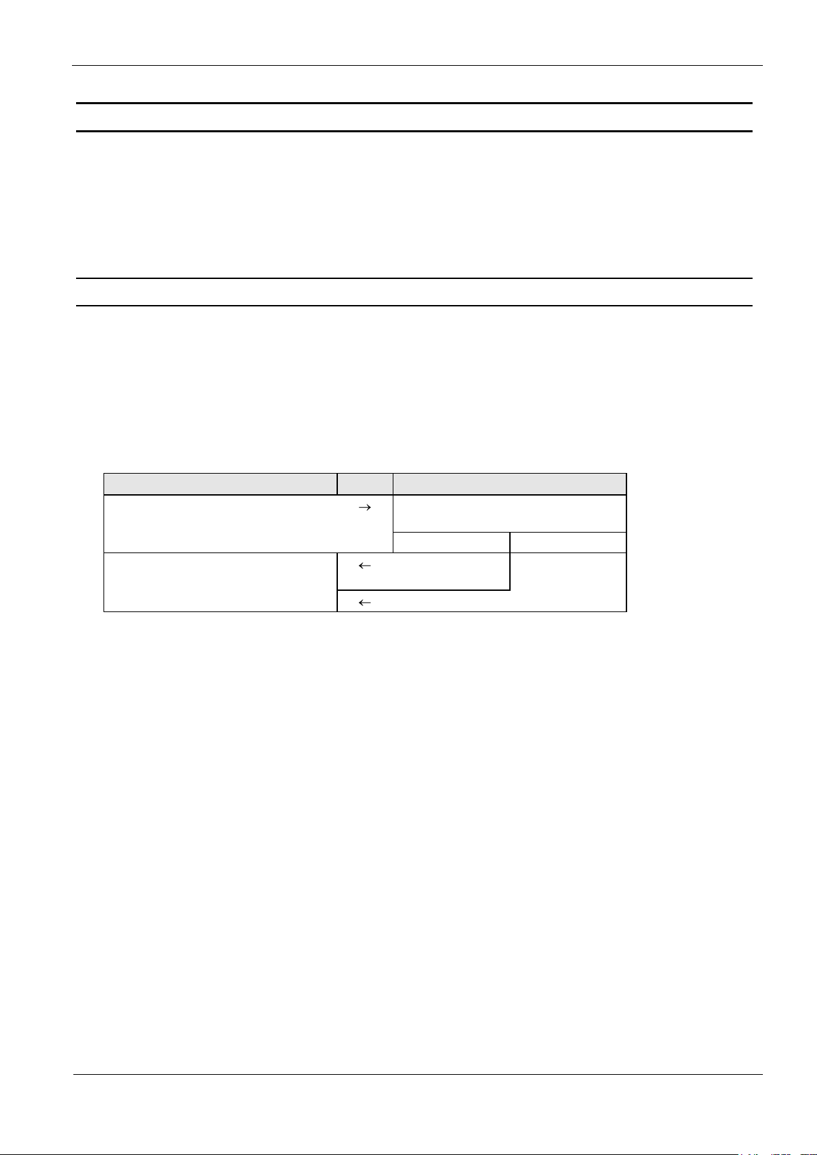
2.1.
Host (Terminal / PC / ....)
Reader
parameter- / control command
parameter received and stored / control
command processed
yes
no
status /
data
error status
Data Transmission between OBID® ID CPR-Reader and Host
Different ways of data transmission between OBID® classic-pro Readers and host (terminal, PC) are
possible. The ISO Host Commands is used for the data exchange between Transponder and host,
whereas the Configuration and Control Commands are for adapting the Reader parameters to the
individual requirements of the applications.
Configuration and Control Commands
This method of data transmission is used for Reader configuration and diagnostics.
The Reader-configuration parameters will be stored in the Reader memory. To store the current
configuration during a power down of the Reader the Reader configuration has to be stored in the
EEPROM. After the Reader was powered up the configuration out of the EEPROM is used.
OBID® classic-pro
Manual
ID CPR30.xx
FEIG ELECTRONIC GmbH
Page 11 of 126
H01114-0e-ID-B.docx
2.2.
Host (Terminal / PC / ....)
Reader
Inventory
to get the UID
Transponder in antenna field?
Yes
No
status /
number of Trans-
ponders / UID
status =
no Transponder
read data from Transponder with UID
Transponder with
correct UID in antenna field?
Yes
No
status /
Transponder read
data
status =
no Transponder
in Reader field
write data to Transponder with UID
Transponder with
correct UID in antenna field?
Yes
No
OK status
status =
no Transponder
in Reader field
ISO Host Commands
The ISO Host Commands provide the exchange of data between a host and Transponders via the
Reader as long as the Transponder remains in the detection range of the Reader.
NOTICE:
During the writing of data on a Transponder, it must be ensured that the Transponder is located within the detection range of the Reader during the entire process. If the Transponder
is removed from detection range of the Reader during a writing process, this will cause a
loss of data.
The Reader distinguishes between the following different addressing modes:
Addressed mode:
Before reading or writing data in addressed mode, the UID of the Transponder has to be
known. This is executed by sending the command “6.1.1. [0x01] Inventory“. If a Transponder is located within the detection range of the Reader at that time, it answers with its UID.
For all following read- / write orders the Transponder must be addressed with its correct
UID.
The following chart will show the necessary steps for the communication with a Transpond-
er in addressed mode:
OBID® classic-pro
Manual
ID CPR30.xx
FEIG ELECTRONIC GmbH
Page 12 of 126
H01114-0e-ID-B.docx
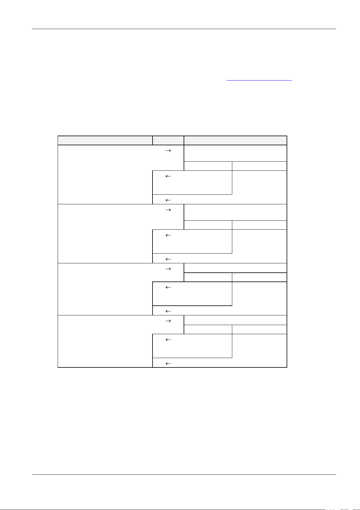
Host (Terminal / PC / ....)
Reader
Inventory
to get the UID
Transponder in antenna field?
Yes
No
status /
number of Trans-
ponders / UID
status =
no Transponder
select Transponder with UID
Transponder with the
correct UID in antenna field?
Yes
No
status /
Transponder read
data
status =
no Transponder
in Reader field
read data
Selected Transponder in antenna field?
Yes
No
status /
Transponder read
data
status =
no Transponder
in Reader field
write data
Selected Transponder in antenna field?
Yes
No
OK status
status =
no Transponder
in Reader field
Selected:
In this mode the Reader communicates only with the one, selected Transponder.
Before reading or writing data in selected mode, the UID of the Transponder has to be
known. This is executed by sending at first the protocol “6.1.1. [0x01] Inventory“. In a
second step the Transponder must be selected with the select command (see: 6.1.2. [0x25]
Select) which must include its UID.
The following chart will show the necessary steps for the communication with a Transpond-
er in selected mode:

OBID® classic-pro
Manual
ID CPR30.xx
FEIG ELECTRONIC GmbH
Page 13 of 126
H01114-0e-ID-B.docx
2.3.
Data Format and Protocol Frames for bi-directional communication
The communication between Reader and connected host (terminal, PC, etc.) is executed by means
of fixed protocols. During data transfer the Reader supplies the required data or a status byte. The
reply contains the transmitted command byte.
There is no reply from the Reader in case of a protocol frame failure.
The Reader supports two different Protocol frames which are the standard and the advanced protocol frame. The Host Application can chose which protocol frame shall used.
If the host application chose advanced protocol frame the Reader will always response with ad-
vanced protocol frame.
If the host application chose the standard protocol frame the Reader’s response will depend on
the length of the response data.
If the response data will result a protocol frame with more than 255 Byte the Reader chose the
advanced protocol frame otherwise the Reader chose the standard protocol frame.
OBID® classic-pro
Manual
ID CPR30.xx
FEIG ELECTRONIC GmbH
Page 14 of 126
H01114-0e-ID-B.docx
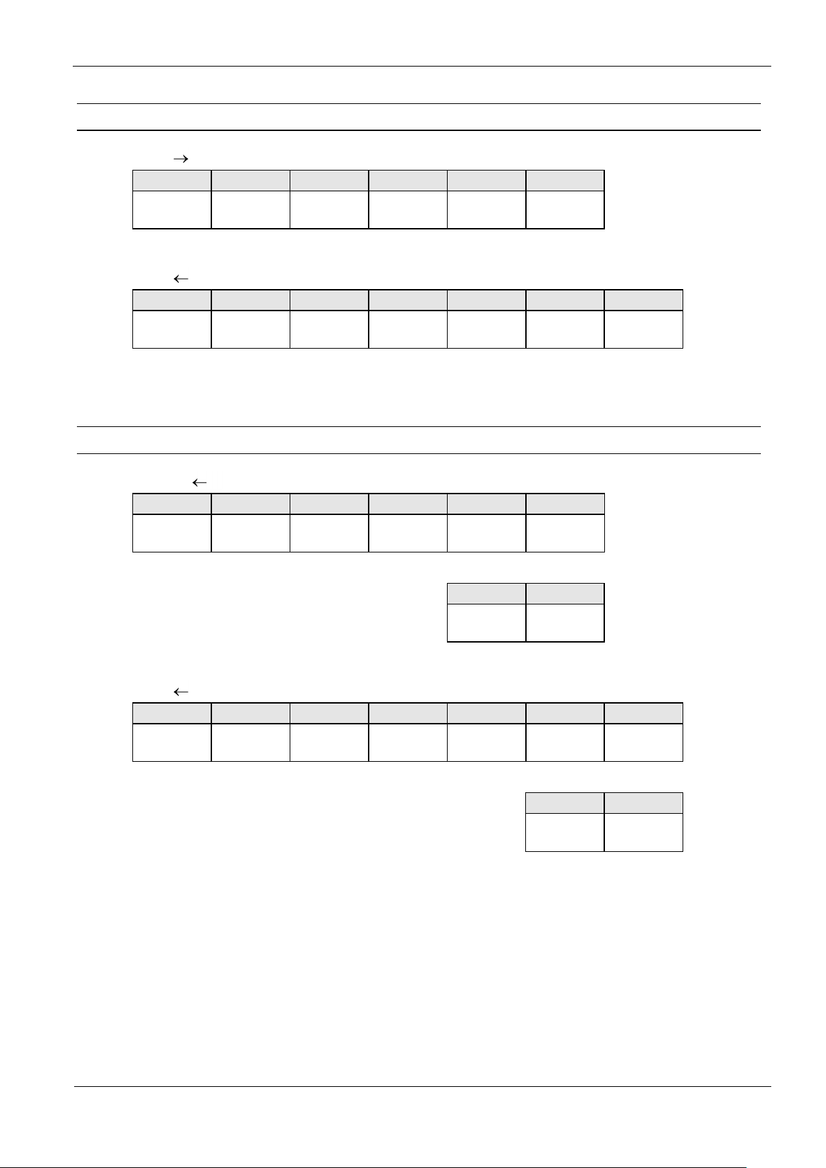
2.3.1.
1 2 3
4...n-2
n-1
n
LENGTH
(n)
COM-ADR
COMMAND
- BYTE
(DATA)
LSB
CRC16
MSB
CRC16
1 2 3
4
(5...n-2)
n-1
n
LENGTH
(n)
COM-ADR
COMMAND
- BYTE
STATUS
(DATA)
LSB
CRC16
MSB
CRC16
2.3.2.
1 2 3 4 5
(6...n-2)
STX
(0x02)
MSB
ALENGTH
LSB
ALENGTH
COM-ADR
COMMAND
- BYTE
(DATA)
n-1
n
LSB
CRC16
MSB
CRC16
1 2 3 4 5
6
(7...n-2)
STX
(0x02)
MSB
ALENGTH
LSB
ALENGTH
COM-ADR
COMMAND
- BYTE
STATUS
(DATA)
n-1
n
LSB
CRC16
MSB
CRC16
Standard Protocol Frame (up to 255 Byte)
Host Reader
Host Reader
Advanced Protocol Frame (recommended to use)
Reader Host
Host Reader

OBID® classic-pro
Manual
ID CPR30.xx
FEIG ELECTRONIC GmbH
Page 15 of 126
H01114-0e-ID-B.docx
2.3.3.
Start bits:
1
Data bits:
8
Stop bits:
1
Parity:
even (default)
odd
none
1
Protocol Elements
LENGTH (n = 6...255):
Number of protocol bytes including LENGTH and CRC16.
COM-ADR:
0...254 address of device in bus mode
NOTICE:
The Reader can be addressed via COM-ADR 255 at any time if a RS232/485 interface
is available!
COMMAND-BYTE:
Defines the Command which the Reader should operate.
STATUS 1:
Includes the status message or protocol data from or to the Reader.
DATA:
Is an optional data field with variable length. The number of DATA byte depends on the
command. The data will be sent always as MSB first if the Reader is in the ISO-Host Command Mode.
CRC16:
Cyclic redundancy check of the protocol bytes from 1 to n-2, as specified by CCITT-CRC16
Polynom 0x8408 (x16 + x12 + x5 + 1 reversed)
Start Value 0xFFFF
In case of USB communication the CRC16 value is not checked by the reader.
STX:
The STX sign (0x02) at the start of protocol indicates an Advanced Protocol-Frame.
ALENGTH (n = 8...65535):
Number of protocol bytes including STX, ALENGTH and CRC16
Data format:
see ANNEX C: Index of Status Bytes

OBID® classic-pro
Manual
ID CPR30.xx
FEIG ELECTRONIC GmbH
Page 16 of 126
H01114-0e-ID-B.docx
2.3.4.
Host Reader:
..
max. TR-RESPONSE-TIME
Host Reader:
..
..
..
max. 12 ms
max. 12 ms
max. 12 ms
Host Reader:
Char n
Char n+1
Char n+2
..
2.3.5.
Timing Conditions
Block timeout:
Defines the time within the reader response can be expected by the host. The host block
timeout shall be set to value longer than the time configured in CFG1.TR-RESPONSETIME.
Character timeout:
Within one protocol, the characters have to follow each other in intervals of maximum
12 ms.
CRC16 Calculation Algorithm for Protocol Frames
Polynom: x16 + x12 + x5 + 1 (reversed) CRC_POLYNOM = 0x8408;
Start Value: 0xFFFF CRC_PRESET = 0xFFFF;
C-Example:
unsigned int crc = CRC_PRESET;
for (i = 0; i < cnt; i++) // cnt = number of protocol bytes without CRC
{
crc ^= DATA[i];
for (j = 0; j < 8; j++)
{
if (crc & 0x0001)
crc = (crc >> 1) ^ CRC_POLYNOM;
else
crc = (crc >> 1);
}
}

OBID® classic-pro
Manual
ID CPR30.xx
FEIG ELECTRONIC GmbH
Page 17 of 126
H01114-0e-ID-B.docx
3.
Byte
0 1 2 3 4 5 6 7 8 9 10
11
12
13
14
15
Contents
PARAMETER
CRC16
Bit:
7 6 5 4 3 2 1 0 Function
LOC
MODE
CFGn: address of configuration block
Configuration Parameters (CFG)
The configuration memory of the Reader is organized in configuration blocks of 16 byte each. These
are divided into 14-byte configuration parameters and a 2-byte CRC16 checksum. Each of these
configuration blocks takes a number (CFG 0...CFG n).
Structure of a configuration block in Reader configuration memory and Reader EEPROM (CFG):
The parameters are stored in two different configuration memory locations:
Reader RAM
Backup EEPROM (used for storing parameter over power down)
Multiple configuration memory locations can be addressed by the value of the parameter CFG-ADR
used in chapter 4. Commands for Reader Configuration
CFG-ADR:
CFGn: memory-address of the required configuration block
LOC: specifies the location of the configuration block (RAM / EEPROM)
MODE: specifies one or all configuration blocks
The EEPROM configuration blocks are protected by a 16 bit CRC-checksum. The examination of
these checksums is executed after each reset of the Reader. If a faulty checksum is found, the
Reader goes into an error status "EE-Init-Mode" and sets the configuration block which is faulty to
the default values.
While the EE-Init-Mode is active, the LED blinks alternately red and green and the Reader answers
external commands with the status "0x10 EEPROM Failure". The "EE-Init-Mode" can be exited now
by a new reset (cold start or 5.2. [0x63] CPU Reset command). If after this the checksums of all
data records are correct, the Reader shifts to the configured operation mode.
Notes:
Malfunctions may occur if parameters are configured outside their described range or if
unspecified parameters have been changed!
A firmware update resets the EEPROM to default settings and the Reader goes into the
error status “EE-Init-mode”.
OBID® classic-pro
Manual
ID CPR30.xx
FEIG ELECTRONIC GmbH
Page 18 of 126
H01114-0e-ID-B.docx
Byte 0 1 2 ......n
contents
RAM-eff.
EEPROM-
eff.
00
res
.....
not marked
Changing of this parameter becomes immediately effective after
writing / saving this
configuration block to
RAM
marked with “00“
these bits or bytes are reserved
for future extensions or for internal testing and manufacturing-functions. These bits or
bytes and also any not described bits and bytes must not
be changed, as this may cause
faulty operation of the Reader.
gray marked
Changing of this parameter only becomes
effective after writing /
saving this configuration
block to EEPROM and
a Reader reset
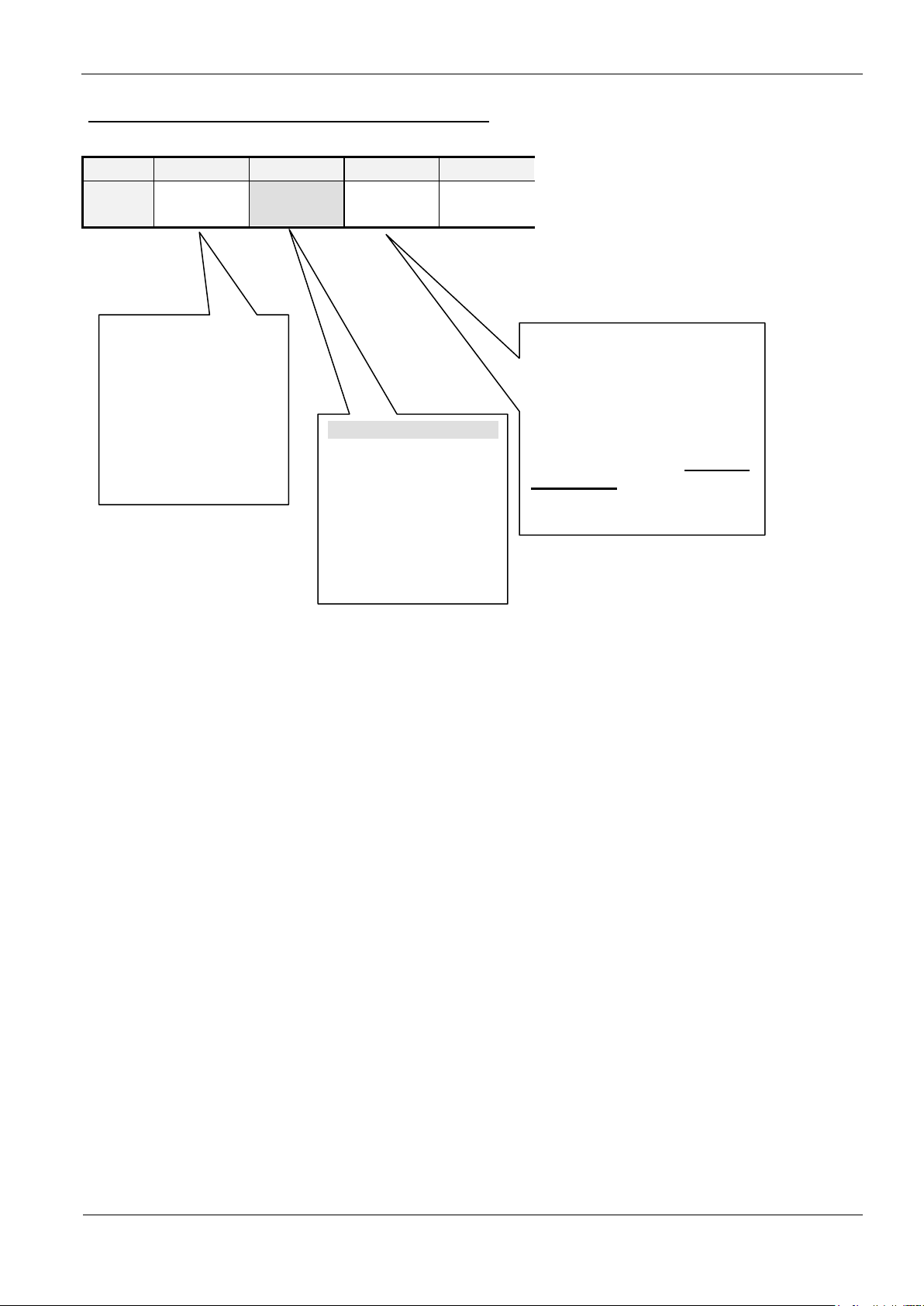
Structure of configuration parameter description.

OBID® classic-pro
Manual
ID CPR30.xx
FEIG ELECTRONIC GmbH
Page 19 of 126
H01114-0e-ID-B.docx
3.1.
Byte 0 1 2 3 4 5
6
Contents
0x00
0x00
0x00
0x00
0x00
0x00
0x00
Default
0x00
0x00
0x00
0x00
0x00
0x00
0x00
Byte 7 8 9 10
11
12
13
Contents
0x00
0x00
0x00
0x00
0x00
0x00
0x00
Default
0x00
0x00
0x00
0x00
0x00
0x00
0x00
CFG0: RFU (Reserved for Future Use)
The configuration block CFG0 is RFU.

OBID® classic-pro
Manual
ID CPR30.xx
FEIG ELECTRONIC GmbH
Page 20 of 126
H01114-0e-ID-B.docx
3.2.
Byte 0 1 2 3 4 5
6
Contents
COM-ADR
0x00
BAUD
TRANS-
FORM
0x00 0x00
TR-
RESPONSE-
TIME
Default
0x00
0x00
0x08
0x01
0x00
0x00
0x00
Byte 7 8 9 10
11
12
13
Contents
TR-
RESPONSE-
TIME
0x00 0x00
0x00
0x00
0x00
READER -
MODE
Default
0x16
0x00 0x00
0x00
0x00
0x00
0x00
2,2 sec.
BAUD
ID CPR30.xx
0x05
4.800
bit/s
0x06
9.600
bit/s
0x07
19.200
bit/s
0x08
38.400
bit/s
0x09
57.600
bit/s
0x0B
115.200
bit/s
0x0D
230.400
bit/s
0x80 - bit/s
0x81 - bit/s
0x82 - bit/s
0x83 - bit/s
1
CFG1: Interface
The parameters of the CFG1 configuration block contain the data communication settings.
COM-ADR:
Bus address of the Reader (0 .. 254) for communication via the asynchronous interface.
Notes:
Do not configure address 255!
Via the COM-ADR 255 in the send protocol, the Reader is able to be addressed at
any time. It answers then with the configured address.
BAUD1:
By means of this byte the baud rate of the asynchronous interface can be defined.
NOTICE:
A plausibility check is performed by writing this parameter to the Reader. If an error occurs the Reader an-
swers with STATUS = 0x11.

OBID® classic-pro
Manual
ID CPR30.xx
FEIG ELECTRONIC GmbH
Page 21 of 126
H01114-0e-ID-B.docx
Bit: 7 6 5 4 3 2 1 0
Function:
0 0 0 0 S D P
1
Make sure that your host system supports the selected baud rate. If not it's im-
possible to communicate with the reader any longer after the baud rate was
changed!
Changing of BAUD only becomes effective after writing / saving configuration
block CFG1 to EEPROM and a reset of the Reader.
The Reader set the baud rate to 38400 bit/s, if the user set an undefined baud rate.
TRANS-FORM1:
By means of this byte, several parameters for the data transmission format of the asynchronous interface can be defined.
P: Kind of Parity
b00: no parity
b01: even parity
b10: odd parity
b11: - do not use -
D: Number of data bits
b0: 8 data bits
b1: - do not use -
S: Number of stop bits
b0: 1 stop bit
b1: - do not use -
NOTICE:
Changing of TRANS-FORM only becomes effective after writing / saving configu-
ration block CFG1 to EEPROM and reset of the Reader.
Always 8 Data Bits and 1 Stop Bits should be used
TR-RESPONSE-TIME:
By means of this parameter the maximum duration for the Transponder command can be
defined.
The TR-RESPONSE-TIME starts after the Reader has received a new command. At the
latest after the TR-RESPONSE-TIME elapsed the Reader will be sent an answer protocol.
In this case, the current commands between Reader and Transponder are aborted.
A plausibility check is performed by writing this parameter to the Reader. If an error occurs the Reader an-
swers with STATUS = 0x11.

OBID® classic-pro
Manual
ID CPR30.xx
FEIG ELECTRONIC GmbH
Page 22 of 126
H01114-0e-ID-B.docx
max. response duration
TR-RESPONSE-TIME
0...65535 * 100 ms
Bit: 7 6 5 4 3 2 1 0
Function:
- - - - - - -
-
NOTICE:
TR-RESPONSE-TIME has no effect for commands for Reader Configuration and
Reader Control.
The block receive timeout of host computer must set to a value TR-RESPONSE-
TIME.
READER-MODE:
By means of this byte, the Reader mode can be defined.
Only ISOHost mode is available

OBID® classic-pro
Manual
ID CPR30.xx
FEIG ELECTRONIC GmbH
Page 23 of 126
H01114-0e-ID-B.docx
3.3.
Byte 0 1 2 3 4 5
6
Contents
0x00
0x00
ONLINE-STATE
0x00
0x00
0x00
Default
0x00
0x00
0x0001
0x00
0x00
0x00
Byte 7 8 9 10
11
12
13
Contents
OFFLINE-STATE
OFFLINE-
DELAY
TAGDETECT-STATE
TAGDETECT
ACTIVATION
TIME
0x00
Default
0x0002
0x14
0x0005
0x04
0x00
2 sec.
400 ms
Bit:
15
14
13
12
11
10 9 8
Function: - - - -
Bit: 7 6 5 4 3 2 1 0
Function:
BUZZER-
-
YELLOW
GRN
CFG2: Inputs / Outputs general
Via the following parameters the operation mode of the LED and the Buzzer can be configured individual separate for offline, online and tag-detect conditions.
ONLINE-STATE:
This Parameter defines the behavior of the signal transmitters if they are not activated by
any other event.
GRN / YEL / BUZZER
The bit combination defines the behavior of the signal transmitter
b00: OFF
b01: ON
b10: FLASHING SLOW
OFFLINE-STATE:
This parameter defines the behavior of the signal transmitter, in case of the reader has detected an offline state. The following cases are possible:
Polling-Mode:
In case of polling mode the reader starts to signalize the offline state if it has received no command from the host for more than the time defined by the parameter
OFFLINE-TIME.

OBID® classic-pro
Manual
ID CPR30.xx
FEIG ELECTRONIC GmbH
Page 24 of 126
H01114-0e-ID-B.docx
Bit:
15
14
13
12
11
10 9 8
Function: - - - -
Bit: 7 6 5 4 3 2 1 0
Function:
BUZZER-
-
YELLOW
GRN
Bit:
15
14
13
12
11
10 9 8
Function: - - - -
Bit: 7 6 5 4 3 2 1 0
Function:
BUZZER-
-
YELLOW
GRN
GRN / YEL / BUZZER
The bit combination defines the behavior of the signal transmitter
b00: OFF
b01: ON
b10: FLASHING SLOW
OFFLINE-DELAY:
This parameter defines the delay in 100 ms increments, after the Reader will signalize the
offline state if he had not received a command via his asynchronous interface.
0 ... 255 x 100 ms 0 ... 25,5 sec
TAGDETECT-STATE:
This parameter defines the behavior of the signal transmitter if a new transponder was detected by the reader
GRN / YEL / RED / BUZZER
The bit combination defines the behavior of the signal transmitter
b00: OFF
b01: ON
b10: FLASHING SLOW
TAGDETECT-ACTIVATION-TIME:
This parameter defines the duration in 100 ms increments, the Reader signalize a transponder was detected.
0 ... 255 x 100 ms 0 ... 25,5 sec

OBID® classic-pro
Manual
ID CPR30.xx
FEIG ELECTRONIC GmbH
Page 25 of 126
H01114-0e-ID-B.docx
3.4.
Byte 0 1 2 3 4 5
6
Contents
TAG-DRV
ISO14443-DRV
0x00
0x00
0x00
Default
0x0038
0x000E
0x00
0x00
0x00
Byte 7 8 9 10
11
12
13
Contents
ISO14443
BIT RATE
0x00
0x00
0x00
0x00
ISO14443
STUPT
ISO14443
FTUR
Default
0x00
0x00
0x00
0x00
0x00
0x03
15 ms
0x1A
Byte:
0
1
Bit:
15
14
13
12
11
10 9 8 7 6 5 4 3 2 1 0
Driver
0 0 0 0 0 0 0 0 0
0
F E D
0 0 0
Default
0 0 0 0 0 0 0 0 0 0 1 1 1 0 0
0
1
CFG3: RF-Interface
The parameters of the CFG3 configuration block contain global Transponder driver and Reader settings.
TAG-DRV1:
Defines the Transponder types that are operated by the Reader.
b0: Driver for the Transponder type is disabled
b1: Driver for the Transponder type is activated
.D: Driver for ISO15693
.E: Driver for ISO14443A
.F: Driver for ISO14443B
Only those Transponder drivers should be active that are used in the current appli-
cation. Thus, the reaction time of the Reader for Transponder read- / writeoperations is reduced and the danger of a parasitic Transponder access is minimized.
A plausibility check is performed by writing this parameter to the Reader. If an error occurs the Reader an-
swers with STATUS = 0x11.

OBID® classic-pro
Manual
ID CPR30.xx
FEIG ELECTRONIC GmbH
Page 26 of 126
H01114-0e-ID-B.docx
Byte:
2
3
Bit:
15
14
13
12
11
10 9 8 7 6 5 4 3 2 1 0
Driver
0 0 0 0 0 0 0 0 0 0 0
0
L4 C B
0
Bit:
7 6 5 4 3 2 1 0 Function
Tx BIT RATE
Rx BIT RATE
- - -
-
ISO14443-DRV:
Defines the ISO 14443 Transponder types that are read/write operated by the Reader.
Reading of the UID is also possible if the driver is inactive, because of the standardized
ISO14443 access conditions.
If more than one Transponder driver is activated The Reader attempted by means of some
indications to decide about the Transponder type.
To guarantee that the Reader only processes the correct Transponder type the not required
drivers should be disabled.
b0: Driver for the Transponder type is disabled
b1: Driver for the Transponder type is activated
B: Driver for my-d proximity SLE55Rxx
C: Driver for NFC Tag-Type 2 (e.g. mifare Ultralight, my-d move, etc.)
L4 Driver for ISO14443A, Part 4 compatible Transponders
ISO14443 BIT RATE:
This parameter defines the highest Bit-Rate which should be used by the Reader. The actual used Bit-Rate depends on the capabilities of the present Transponder. If the adjusted
Bit-Rate is not support by the Transponder the Reader select the highest supported BitRate of the Transponder.
TX BIT RATE
Used for bit rate selection from Reader to Transponder
b00: 106 kbit / s
RX BIT RATE
Used for bit rate selection from Transponder to Reader
b00: 106 kbit / s
ISO14443 STUPT (1 ... 255 * 5 ms = 5 ms ... 1,275 sec):
The Startup Time defines a delay-time which is required by a ISO14443 Transponder for
startup after the RF-Field was switched on (e. g. after a command [0x69] RF Reset).

OBID® classic-pro
Manual
ID CPR30.xx
FEIG ELECTRONIC GmbH
Page 27 of 126
H01114-0e-ID-B.docx
Bit:
7 6 5 4 3 2 1
0
Function
UID-
ORDER
OPTI
ERROR_RETRY
PLIC
BSLCT
NOTICE:
The value of ISO14443 STUPT must be considered for calculating the TRRESPONSE-TIME (see CFG1)
ISO14443 FTUR:
In this parameter byte are some special features combined.
BSLCT (only ISO 14443B Transponder)
The Reader principally use 106 kBit / for the first communication cycle. If the
This bit selects the response behavior for ISO 14443B Transponder with Bit-Rates
above 106 kBit / s.
Transponder supports a higher Bit-Rate and this is configured by the parameter
ISO14443 BIT RATE the Reader selects the highest possible Bit-Rate.
Unfortunately the reception from the Transponder could be on 106 kBit / s ore on
the new higher Bit-Rate.
b0: The first reception after a Bit-Rate change is expected with 106 kBit / s.
b1: The first reception after a Bit-Rate change is expected with the selected
higher Bit-Rate.
PLIC (only ISO 14443-4 Transponder)
This bit enables the power level indicator check function of the Reader.
b0: Power level check is disabled.
b1: Power level check is enabled.
The power level indicator of ISO 14443-4 Transponders will be interpreted
by the Reader if it is supported by the Transponder.
If a Transponder response indicates insufficient power the Reader breaks
the present command and sends an error status.
ERROR_RETRY (only ISO 14443-4 Transponder)
This parameter defines the maximum number of automatic retry loops in case of
transmission or protocol errors as described in ISO 14443-4.
b00: disables retry loop
b01: 1 retry loop
b10 2 retry loops
b11: 3 retry loops

OBID® classic-pro
Manual
ID CPR30.xx
FEIG ELECTRONIC GmbH
Page 28 of 126
H01114-0e-ID-B.docx
OPTI (only ISO14443A Transponder)
By means of this bit some optional information's could be displayed for ISO14443A
in the [0x01] inventory response byte OPT_INFO (see also 6.1.1. [0x01] Inventory)
b0: The OPT_INFO byte in [0x01] inventory response is always set to 0.
b1: The OPT_INFO byte in [0x01] inventory response includes further Infor-
mation's.
UID_ORDER (only ISO14443A Transponder)
By means of this bit the byte order of the UID of ISO14443A Transponder can be
swapped.
b0: The UID will be transferred as described in 6.1.1.1. Response-Data - ISO
14443A (TR-TYPE = 0x04).
b1: The byte order of the transferred UID will be swapped (UID transfer will be
carried out like described in ISO14443).

OBID® classic-pro
Manual
ID CPR30.xx
FEIG ELECTRONIC GmbH
Page 29 of 126
H01114-0e-ID-B.docx
3.5.
Byte 0 1 2 3 4 5
6
Contents
0x00
0x00
0x00
0x00
ISO15693-
MODE
ISO15693-
AFI
ISO15693-
OPTION
Default
0x00
0x00
0x00
0x00
0x10
0x00
0x00
Byte 7 8 9 10
11
12
13
Contents
0x00
ISO14443B-
AFI
0x00
0x00
0x00
0x00
ISO15693
BLOCKSIZE
Default
0x00
0x00
0x00
0x00
0x00
0x00
0x04
Bit:
7 6 5 4 3 2 1 0 Function
0 0 AFI
NO-TS 0 0 0 0
Bit:
7 6 5 4 3 2 1 0 Function
0 0 0 0 WR-OPTION
0
0
CFG4: Transponder Parameters
The parameters of the CFG4 configuration block contain general Transponder settings.
ISO15693-MODE: (only ISO15693 Transponders)
NO-TS
b0: 16 timeslots
b1: 1 timeslot
NOTICE:
Anticollision is only possible if NO-TS=16.
AFI
b0: disabled
b1: enabled
ISO15693-AFI: (only ISO15693 Transponders)
Application Family Identifier to select a Transponder
ISO15693-OPTION: (only ISO15693 Transponder)
WR-OPTION:
NOTICE:
If WR-OPTION is automatically set, the Reader sets the WR-OPTION to 0, if the ISO-Host
Command is in non-addressed mode.
b00: automatically set
b10: Tag Option = 0
b11: Tag Option = 1

OBID® classic-pro
Manual
ID CPR30.xx
FEIG ELECTRONIC GmbH
Page 30 of 126
H01114-0e-ID-B.docx
Bit:
7 6 5 4 3 2 1 0 Function
Read Mode
Blocksize
DB-Blocksize
ISO14443B-AFI: (only ISO14443B Transponders)
Application Family Identifier for ISO14443 type B Transponder. For more information's refer
to ISO14443-3.
ISO15693-BLOCKSIZE
DB-Blocksize
Defines the block size of an ISO-transponder which is not listed chapter 8. Supported ISO Host commands or if the transponder is used in the non-addressed
mode.
Range: 0x01 ... 0x1F
A value of 0x00 will be automatically set to a block size of 4 Byte.
Blocksize
b0: Automatic (If transponder is known)
b1: Manuel (As specified in DB-Blocksize)
Read Mode
b00: Automatic Mode (If transponder is known)
b01 Single Read
b10 Multiple Read
 Loading...