

Page 1
Handbuch
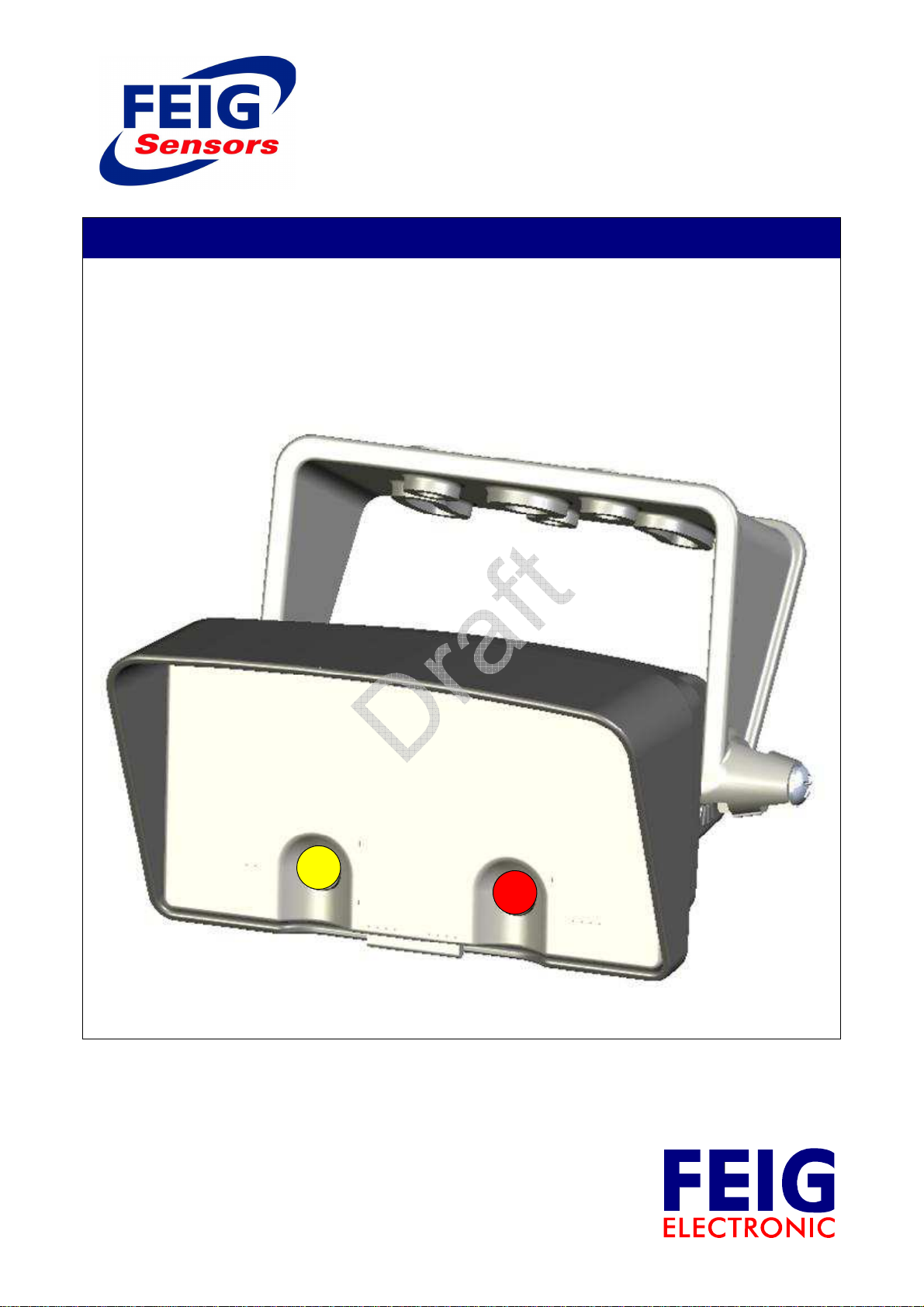
Manual
Digital Radar Motion Detector - MWD BPC
Digitaler Radar Bewegungsmelder
public (B)
23.06.16
MWD BPC_Handbuch_mehrsprachig_1.doc
Page 2

Handbuch MWD BPC
Wichtig!
Lesen Sie unbedingt die Funktionsbeschreibung, bevor Sie das Gerät betreiben,
anschließen oder in Betrieb setzen.
Hinweise
Copyright 2016 by
FEIG ELECTRONIC GmbH
Lange Straße 4
D-35781 Weilburg-Waldhausen
Tel.: +49 6471 3109-0
http://www.feig.de
Alle früheren Ausgaben verlieren mit dieser Ausgabe ihre Gültigkeit.
Die Angaben in diesem Dokument können ohne vorherige Ankündigung geändert werden.
Weitergabe sowie Vervielfältigung dieses Dokumentes, Verwertung und Mitteilung seines Inhalts sind nicht
gestattet, soweit nicht ausdrücklich zugestanden. Zuwiderhandlung verpflichtet zu Schadenersatz. Alle
Rechte für den Fall der Patenterteilung oder Gebrauchsmuster-Eintragung vorbehalten.
Dieses Handbuch richtet sich speziell an den Inbetriebnehmer des Bewegungsmelders MWD BPC von FEIG
ELECTRONIC GmbH. Die Inbetriebnahme des Bewegungsmelders darf nur von anerkannt ausgebildeten
Elektrofachkräften, die mit den Sicherheitsstandards der elektrischen Automatisierungstechnik vertraut sind,
erfolgen.
Für die Vollständigkeit des Handbuchs ist ausschließlich der Inverkehrbringer des Bewegungsmelders MWD
BPC verantwortlich.
Die Zusammenstellung der Informationen in diesem Dokument erfolgt nach bestem Wissen und Gewissen.
FEIG ELECTRONIC GmbH übernimmt keine Gewährleistung für die Richtigkeit und Vollständigkeit der
Angaben in diesem Dokument. Insbesondere kann FEIG ELECTRONIC GmbH nicht für Folgeschäden auf
Grund fehlerhafter oder unvollständiger Angaben haftbar gemacht werden.
Da sich Fehler, trotz aller Bemühungen nie vollständig vermeiden lassen, sind wir für Hinweise jederzeit
dankbar.
Die in diesem Dokument gemachten Installationsempfehlungen gehen von günstigsten Rahmenbedingungen aus. FEIG ELECTRONIC GmbH übernimmt keine Gewähr für die einwandfreie Funktion in systemfremden Umgebungen.
FEIG ELECTRONIC GmbH übernimmt keine Gewährleistung dafür, dass die in diesem Dokument enthaltenden Informationen frei von fremden Schutzrechten sind. FEIG ELECTRONIC GmbH erteilt mit diesem
Dokument keine Lizenzen auf eigene oder fremde Patente oder andere Schutzrechte.
Gewährleistungsansprüche gegen FEIG ELECTRONIC GmbH stehen nur dem unmittelbaren Vertragspartner zu und sind nicht übertragbar. Es wird nur die Gewährleistung für die von FEIG ELECTRONIC GmbH
gelieferten Produkte übernommen. Eine Haftung für das Gesamtsystem ist ausgeschlossen.
Die Beschreibung der Produkte, deren Einsatz, Möglichkeiten und Leistungsdaten gelten nicht als zugesicherte Eigenschaften und stehen unter dem Vorbehalt technischer Änderungen.
Allgemeine Hinweise zu diesem Dokument
In dieser Funktionsbeschreibung werden folgende Zeichen benutzt, um Leser auf verschiedene Gefahrenpunkte und nützliche Tipps hinzuweisen.
WARNUNG
Gefährdung von Personen hin, wenn die
Prozedur nicht wie beschrieben durchgeführt
wird.
ACHTUNG
Bewegungsmelders hin.
weist auf eine mögliche
weist auf eine Gefährdung des
WICHTIG weist auf Informationen hin, die
wichtig für die Funktion des Bewegungsmelders sind.
weist auf Informationen hin, die für den
Gebrauch des Bewegungsmelders nützlich, aber
nicht unbedingt notwendig sind
FEIG ELECTRONIC GmbH Seite 2 von 23 MWD BPC_Handbuch_mehrsprachig_1.doc
Page 3

Handbuch MWD BPC
Inhalt
1
Sicherheitshinweise 4
2
Allgemeines 5
3
Technische Daten 5
4
Zulassungen 6
4.1
Europa (CE)................................................................................................................................... 6
4.2
Schweiz (BAKOM) ........................................................................................................................ 7
4.3
USA (FCC) / Canada (IC) .............................................................................................................. 7
5
Montage des Bewegungsmelders 8
5.1
Auswahl des Montageortes ......................................................................................................... 8
5.2
Montage des Haltewinkels .......................................................................................................... 9
5.3
Montage des Bewegungsmelder-Gehäuses .............................................................................. 9
5.4
Elektrischer Anschluss ............................................................................................................. 10
6
Anzeige während des Betriebs 11
7
Ursachen von Störungen 12
FEIG ELECTRONIC GmbH Seite 3 von 23 MWD BPC_Handbuch_mehrsprachig_1.doc
Page 4

Handbuch MWD BPC
1 Sicherheitshinweise
ACHTUNG: WICHTIGE SICHERHEITSANWEISUNGEN
FÜR DIE SICHERHEIT VON PERSONEN IST ES WICHTIG, DIESEN ANWEISUNGEN FOLGE ZU
LEISTEN. DIESE ANWEISUNGEN SIND AUFZUBEWAHREN:
- Alle Installations-, Inbetriebnahme-, und Instandhaltungsarbeiten sind ausschließlich von qualifiziertem Fachpersonal durchzuführen. Es müssen insbesondere die folgenden Vorschriften beachtet
werden: VDE0100, EN 50110 (VDE0105), EN 60204 (VDE0113), EN 50178 (VDE0160), EN 60335
(VDE0700), Brandverhütungsvorschriften, Unfallverhütungsvorschriften, sowie die einschlägigen
Vorschriften für Industrietore (ZH1/494, EN12453, EN12978)
- Ein Öffnen des Bewegungsmelders ist nur bei abgeschalteter Versorgungsspannung zulässig.
- Wenn die Anschlussleitung dieses Gerätes beschädigt wird, muss sie durch den Hersteller oder
seinen Kundendienst oder eine ähnlich qualifizierte Person ersetzt werden, um Gefährdungen zu
vermeiden.
- Das Einschalten bzw. Betreiben eines im inneren betauten Bewegungsmelders ist nicht zulässig. Es
kann zur Zerstörung des Bewegungsmelders führen.
- Es muss sichergestellt werden, dass beim Einschalten der Versorgung, sowie beim Betrieb des
Bewegungsmelders, der spezifizierte Arbeitstemperaturbereich eingehalten wird.
- Ein Betreiben des Bewegungsmelders mit beschädigten Gehäuse ist verboten. Beschädigte
Gehäuse sind auszutauschen.
- Die Einstellung der Parameter müssen überprüft werden. Die Einstellung der Parameter und anderer
Bedienelemente darf nur von unterwiesenem Personal durchgeführt werden.
- Das Gerät darf nur für den vom Hersteller vorgesehenen Zweck verwendet werden.
- Die Bedienungsanleitung ist zugriffsfähig aufzubewahren und jedem Benutzer auszuhändigen.
- Unzulässige Veränderungen und die Verwendung von Ersatzteilen und Zusatzeinrichtungen, die
nicht vom Hersteller des Gerätes verkauft oder empfohlen werden, können Brände, elektrische
Schläge und Verletzungen verursachen. Solche Maßnahmen führen daher zu einem Ausschluß der
Haftung und der Hersteller übernimmt keine Gewährleistung.
- Für das Gerät gelten die Gewährleistungsbestimmungen des Herstellers in der zum Zeitpunkt des
Kaufs gültigen Fassung. Für eine ungeeignete, falsche manuelle oder automatische Einstellung von
Parametern für ein Gerät bzw. ungeeignete Verwendung eines Gerätes wird keine Haftung übernommen.
- Reparaturen dürfen nur vom Hersteller durchgeführt werden.
- Das Verlöschen einer Betriebsanzeige ist kein Indikator dafür, dass das Gerät vom Netz getrennt
und spannungslos ist
- Der Benutzer ist dafür verantwortlich, dass das Gerät nach den anerkannten technischen Regeln im
Aufstellungsland sowie anderen regionalen gültigen Vorschriften aufgestellt und angeschlossen wird.
Dabei sind Kabeldimensionierung, Absicherung, Erdung, Abschaltung, Trennung, Isolationsüberwachung und der Überstromschutz besonders zu berücksichtigen.
- Der Betrieb von Niederspannung an den Relaisausgängen ist nicht zulässig.
- Das Gerät darf im Sinne der Maschinenrichtlinie 89/392/EWG, Anhang IV nicht als Sicherheitsbauteil
verwendet werden. In Anlagen mit erhöhtem Gefährdungspotential sind zusätzliche Sicherheitseinrichtungen erforderlich!
- Bei einem dauerhaften Abstand von mindestens 3cm zwischen Körper und Planarantenne wird eine
Gesundheitsgefährdung durch Elektromagnetische Felder (EMF) nach 1999/519/EG vermieden!
- Die Hartgoldauflage der Relaiskontakte wird bei Schaltströmen über 100 mA zerstört. Relais mit
derart vorbelasteten Kontakten können nur noch Ströme über 100 mA zuverlässig schalten!
- Beim Betrieb in unmittelbarer Nähe von Folientoren sind geeignete Maßnahmen an der Toranlage zu
zu Beschädigungen des Bewegungsmelders führen.
Mit diesen Sicherheitshinweisen wird kein Anspruch auf Vollständigkeit erhoben. Bei Fragen zu dem Produkt
sprechen Sie bitte Ihren Lieferanten an.
Der Hersteller hat die Gerätehardware und Software, sowie die Produktdokumentation sorgfältig geprüft,
kann aber keine Gewährleistung über völlige Fehlerfreiheit übernehmen.
ergreifen um statische Aufladungen der Torfolie abzuführen.
WARNUNG
Ein Missachten der Sicherheitshinweise kann zur gesundheitlichen Gefährdung oder
FEIG ELECTRONIC GmbH Seite 4 von 23 MWD BPC_Handbuch_mehrsprachig_1.doc
Page 5

Handbuch MWD BPC
2 Allgemeines
Der Radar-Bewegungsmelder MWD BPC arbeitet mit einer Planar-Mikrowellen-Antenne und dient zur
Zufahrts- und Zugangserkennung an Industrietoren.
Das Gerät ist für die Montage im Außenbereich vorgesehen und voreingestellt für typische Toranwendungen.
Die Bedienung erfolgt über die mit dem Gerät verbundene Torsteuerung. Die Bedienerführung erfolgt dabei
über die Anzeige der Torsteuerung.
Für beide Kanäle des Bewegungsmelders können die Ansprechempfindlichkeit und die Richtungslogik
eingestellt werden. Außerdem kann der Melder zwischen Personen und Fahrzeugen unterscheiden und
Querverkehr ausblenden.
3 Technische Daten
Abmessungen Gehäuse (B x H x T): 135x65x130 mm
Material
Gehäuse und Haltebügel
Deckel
Gewicht mit Haltebügel 160 g
Schutzart IP65
Versorgungsspannung 12-27 V AC, 50 – 60 Hz
Leistungsaufnahme typ. 0,8W
Zulässige Betriebstemperatur
Lagertemperatur
Luftfeuchtigkeit
Frequenz 24,125 GHz
Sendeleistung typ. 40 mW EIRP
maximale Montagehöhe 7m
Anzeige 2 LED
Anschlüsse Eingang (IN), CAN + Versorgung, M8-SnapIn Stecker
Vernetzung Bis zu 4 Bewegungsmelder an einer Torsteuerung
Entsorgen Sie das Produkt am Ende seiner Lebensdauer
gemäß den geltenden gesetzlichen Bestimmungen !
ASA
PC
12-30 V DC, GND muss mit PE verbunden sein.
SELV, Stromquelle begrenzter Leistung nach EN 60950-1
max. 1,2W
-20 °C bis +55 °C
-30 °C bis +75 °C
< 95% nicht betauend
max. 100 mW EIRP
Textanzeige erfolgt über Torsteuerung
Ausgang (OUT), CAN + Versorgung, M8-SnapIn Buchse
FEIG ELECTRONIC GmbH Seite 5 von 23 MWD BPC_Handbuch_mehrsprachig_1.doc
Page 6

Handbuch MWD BPC
-
03, Annex
Weilburg
Place & date of issue
Name and signature
This declaration attests to conformity with the named Directives but does not represent assurance of properties. The
4 Zulassungen
4.1 Europa (CE)
Declaration of Conformity
in accordance with the
Radio and Telecommunication Terminal
Equipment Act (FTEG)
and
Directive 1999/5/EC (R&TTE Directive)
Product Manufacturer :
Product Designation :
Product Description : 24 GHz Radar Motion Detector
Radio equipment, Equipment
class (R&TTE)
FEIG ELECTRONIC GmbH
Lange Strasse 4
D-35781 Weilburg-Waldhausen
Germany
Phone: +49 6471 3109 0
MWD BP
Class 2: (ERC/REC 70
:
Detecting Movement and Alert)
6 – Equipment for
FEIG ELECTRONIC GmbH declares that the radio equipment complies with the essential requirements
of §3 and the other relevant provisions of the FTEG (Article 3 of the R&TTE Directive), when used for its
intended purpose.
Standards applied :
Health and safety requirements pursuant to
FTEG § 3 (1) 1 and R&TTE Article 3(1) a)
Protection requirements concerning electromagnetic
compatibility § 3 (1) 2. (Article 3(1) b))
Measures for the efficient use of the radio frequency
spectrum pursuant to § 3 (2) (Article 3(2))
EU-Recommendation 1999/519/EC
EN 60950-1:2001
ETSI EN 301 489-1 V1.8.1
ETSI EN 301 489-3 V1.4.1
ETSI EN 300 440-1 V1.4.1
ETSI EN 300 440-2 V1.2.1
-Waldhausen, 02.11.2009
Eldor Walk
safety guidelines in the accompanying product documentation must be observed.
FEIG ELECTRONIC GmbH Seite 6 von 23 MWD BPC_Handbuch_mehrsprachig_1.doc
Page 7

Handbuch MWD BPC
4.2 Schweiz (BAKOM)
Dieses Gerät darf in der Schweiz betrieben werden.
4.3 USA (FCC) / Canada (IC)
FCC ID: PJMMWDBPC
IC: 6633A-MWDBPC
This device complies with Industry Canada licence-exempt RSS standard(s) and part 15 of the FCC
Rules.
Operation is subject to the following two conditions:
(1) this device may not cause interference, and
(2) this device must accept any interference, including interference that may cause undesired
operation of the device.
Warning: Changes or modifications not expressly approved by the party responsible for compliance
could void the user's authority to operate the equipment.
Le présent appareil est conforme aux CNR d'Industrie Canada applicables aux appareils radio exempts
de licence.
L'exploitation est autorisée aux deux conditions suivantes:
(1) l'appareil ne doit pas produire de brouillage, et
(2) l'appareil doit accepter tout brouillage radioélectrique subi, même si le brouillage est susceptible
d'en compromettre le fonctionnement
This equipment has been tested and found to comply with the limits for a Class B digital device,
pursuant to Part 15 of the FCC Rules. These limits are designed to provide reasonable protection
against harmful interference in a residential installation. This equipment generates, uses and can
radiate radio frequency energy and, if not installed and used in accordance with the instructions, may
cause harmful interference to radio communications. However, there is no guarantee that interference
will not occur in a particular installation. If this equipment does cause harmful interference to radio or
television reception, which can be determined by turning the equipment off and on, the user is
encouraged to try to correct the interference by one or more of the following measures:
• Reorient or relocate the receiving antenna.
• Increase the separation between the equipment and receiver.
• Connect the equipment into an outlet on a circuit different from that to which the receiver is
connected.
•
Consult the dealer or an experienced radio/TV technician for help
.
FEIG ELECTRONIC GmbH Seite 7 von 23 MWD BPC_Handbuch_mehrsprachig_1.doc
Page 8

Handbuch MWD BPC
5 Montage des Bewegungsmelders
WARNUNG
Während der Montage des Bewegungsmelders ist die Anlage spannungsfrei zu
schalten.
ACHTUNG
• Vor der Montage ist der Bewegungsmelders auf eventuelle Transport- oder sonstige
Beschädigungen zu überprüfen. Beschädigungen im Inneren des Bewegungsmelders können
unter Umständen zu erheblichen Folgeschäden an dem Bewegungsmelder bis hin zur
Gesundheitsgefährdung des Anwenders führen.
• Elektrostatische Entladung kann zu Schäden oder Zerstörungen führen.
5.1 Auswahl des Montageortes
Das Gerät wird mittig oberhalb des zu überwachenden Bereiches montiert. Dabei ist Wand- und Deckenmontage möglich. Die maximale Montagehöhe beträgt ca. 7m.
WICHTIG
Das Gerät ist vibrationsfrei zu montieren.
Um Fehlauslösungen zu vermeiden dürfen sich im Strahlungsfeld des Gerätes keine bewegenden
Gegenstände befinden.
Es dürfen keine Leuchtstoffröhren im Strahlungsfeld des Melders hängen.
Die Strahlungsfelder zweier Bewegungsmelder dürfen sich nicht kreuzen, da dies zu Fehlaus-
lösungen führen kann.
Nicht hinter Gegenständen, Gebäudeelementen oder Abdeckungen montieren.
Ist der Bewegungsmelder Regen oder Schnee ausgesetzt, so sollte die Erfassung auf annähernde
Richtung eingestellt werden, da sich Niederschlag typischer Weise vom Gerät entfernt und somit
keine Fehlauslösung verursacht.
Durch leitfähige Fußböden können bei nahezu senkrechter Abstrahlrichtung Fehlauslösungen durch
Reflexionen auftreten.
FEIG ELECTRONIC GmbH Seite 8 von 23 MWD BPC_Handbuch_mehrsprachig_1.doc
Page 9

Handbuch MWD BPC
5.2 Montage des Haltewinkels
Der Haltewinkel ist für Wand- und Deckenmontage geeignet.
100,0 mm (39.37 inch)
38,0 mm (14.96 inch)
4,5 mm (1.77 inch) 4,5 mm (1.77 inch)8,0 mm (3.14 inch)
44,0 mm (17.32 inch)
19,0 mm (7.48 inch)
54,0 mm (21.25 inch)
Abbildung 1: Haltewinkel
5.3 Montage des Bewegungsmelder-Gehäuses
Nach der Montage des Haltewinkels ist das
Bewegungsmelder-Gehäuse am Montagewinkel
mit den beiliegenden Schrauben zu befestigen.
angebrachte Winkelteilung in 15°-Schritten hilft
bei der genauen Ausrichtung des Gerätes.
Maximal kann der Winkel um 180° gedreht
werden.
Abbildung 2: Befestigungsschraube und
Winkelteilung
Ø4,5 mm (1.77 inch)
Die am Gehäuse des Bewegungsmelders
FEIG ELECTRONIC GmbH Seite 9 von 23 MWD BPC_Handbuch_mehrsprachig_1.doc
Page 10

Manual MWD BPC
5.4 Elektrischer Anschluss
Abbildung 3: Anschluss
FEIG ELECTRONIC GmbH Page 10 of 23 MWD BPC_Handbuch_mehrsprachig_1.doc
Page 11

Manual MWD BPC
6 Anzeige während des Betriebs
Abbildung 4: LED´s
Zustand LED 1, gelb LED 2, rot
Keine Spannungsversorgung Aus Aus
Versorgungsspannung ok 1Hz ständig Aus
CAN-Fehler Aus 4Hz ständig
Kanal 1 Objekt erkannt An X
Kanal 2 Objekt erkannt X An
Kanal 1 und 2 Objekt erkannt An An
Detektor in Steuerung selektiert 2Hz ständig synchron 2 Hz ständig synchron
FEIG ELECTRONIC GmbH Page 11 of 23 MWD BPC_Handbuch_mehrsprachig_1.doc
Page 12

Handbuch MWD BPC
7 Ursachen von Störungen
Bei Fehlreaktionen des Bewegungsmelders können
-
bewegende Teile im Umfeld,
-
Vibrationen, die sich über den Montagebügel auf das Gerät übertragen,
-
elektrische Störungen über das Anschlusskabel,
-
elektrische Felder (Funk),
-
Leuchtstoff- oder Gasentladungslampen im Erfassungsfeld,
-
Reflexion der Radar-Strahlen an leitenden Böden oder Wänden
Störungsursachen sein.
FEIG ELECTRONIC GmbH Seite 12 von 23 MWD BPC_Handbuch_mehrsprachig_1.doc
Page 13

Manual MWD BPC
Important!
Read this operating manual prior to connecting, commissioning or operating the
device.
Notes
Copyright 2007 by
FEIG ELECTRONIC GmbH
Lange Straße 4
D-35781 Weilburg-Waldhausen
Tel.: +49 6471 3109-0
http://www.feig.de
This manual invalidates all previous versions.
The information in this document can be modified without prior notice.
The transfer or reproduction of this document, as well as the assessment and dissemination of its content
are prohibited unless expressly permitted. Offenders shall be held liable for damages. All patent rights and
utility patent registration rights reserved.
This manual is specifically addressed to the commissioning technicians of the MWD BPC Motion Detector
from FEIG ELECTRONIC GmbH. The commissioning of the motion detector must only be performed by
qualified electricians who are familiar with the safety standards of electrical automation technology.
The supplier of the MWD BPC Motion Detector is exclusively responsible for the completeness of the
manual.
The information in this document has been compiled according to the best of our knowledge and belief. FEIG
ELECTRONIC GmbH makes no guarantee for the correctness and completeness of the information in this
document. In particular, FEIG ELECTRONIC GmbH cannot be made liable for consequential damages due
to erroneous or incomplete information.
As errors can never be totally avoided despite all efforts, we are always grateful for any information you
could give us.
The installation recommendations made in this document are based on the most favourable conditions FEIG
ELECTRONIC GmbH accepts no guarantee for faultless operation in extraneous environments.
FEIG ELECTRONIC GmbH makes no guarantee that the information contained in this document is not
subject to foreign property rights FEIG ELECTRONIC GmbH does not assign any licences to its own or thirdparty patents or other property rights with this document.
Guarantee claims against FEIG ELECTRONIC GmbH can only be made by the direct contracting party and
are not transferable, Any guarantee only applies to the products supplied by FEIG ELECTRONIC GmbH.
Any liability for the complete system is excluded.
The specification of the products, their use, features and performance data do not count as guaranteed
properties and are subject to technical changes.
General information about this document
The following symbols are used in this function description to alert the user to various hazards
and useful tips.
WARNING
persons if the procedure is not performed as
described.
ATTENTION
device.
alerts to a possible hazard to
alerts to possible damage to the
IMPORTANT alerts to information which is
important to the function of the device.
refers to useful information which is useful but
not absolutely necessary for using the device.
FEIG ELECTRONIC GmbH Page 13 of 23 MWD BPC_Handbuch_mehrsprachig_1.doc
Page 14

Manual MWD BPC
Contents
Notes 13
General information about this document 13
1
Safety information 15
2
General 16
3
Technical Data 16
4
Approvals 17
4.1
Europe (CE)................................................................................................................................. 17
4.2
Switzerland (BAKOM) ................................................................................................................ 18
4.3
USA (FCC) / Canada (IC) ............................................................................................................ 18
5
Installation of the motion detector 19
5.1
Selection of the installation location ....................................................................................... 19
5.2
Mounting of the retaining bracket ............................................................................................ 20
5.3
Mounting the motion detector case ......................................................................................... 20
5.4
Electrical connection ................................................................................................................. 21
6
Display during use 22
7
Causes of faults 23
FEIG ELECTRONIC GmbH Page 14 of 23 MWD BPC_Handbuch_mehrsprachig_1.doc
Page 15

Manual MWD BPC
1 Safety information
ATTENTION: IMPORTANT SAFETY INSTRUCTIONS
IT IS IMPORTANT FOR THE SAFETY OF PERSONS TO OBSERVE THESE INSTRUCTIONS. THESE
INSTRUCTIONS MUST BE KEPT:
- All work concerning installation, set-up and maintenance must be carried out exclusively by qualified
staff. The following regulations must be specifically observed: VDE0100, EN 50110 (VDE0105), EN
60204 (VDE0113), EN 50178 (VDE0160), EN 60335 (VDE0700), fire prevention regulations,
accident prevention regulations and the regulations relevant to industrial gates (ZH1/494, EN12453,
EN12978)
- Opening the motion detector is only permitted when the power supply is switched off.
- If the connecting cable of this device is damaged, it must be replaced by the manufacturer, the
manufacturer's customer service or a similarly qualified person in order to avoid hazards.
- The motion detector must not be switched on or operated if the inside is wet. This can destroy the
motion detector.
- It must be ensured when switching on the power supply and during operation of the motion detector
that the specified operating temperature range is maintained.
- Operating the motion detector with damaged case is prohibited. Damaged case must be replaced.
- The parameter settings must be checked. Adjusting the parameters and other operating elements
must only be carried out by qualified staff.
- The device must only be used for the purpose intended by the manufacturer.
- The operating instructions must be kept in an accessible place and given to every user.
- Unauthorised modifications and the use of replacement parts and additional equipment not sold or
recommended by the manufacturer of the device can cause fires, electric shocks and injuries. Such
actions therefore result in an exclusion of liability and the manufacturer accepts no guarantee claims.
- The manufacturer’s guarantee conditions in force at the time of purchase of the device are
applicable.. No liability is accepted for an unsuitable, incorrect manual or automatic parameter
setting for a device or for improper use of a device.
- Repairs must only be carried out by the manufacturer.
- The extinguishing of an operating indicator lamp does not mean that the device is disconnected from
the mains and de-energised.
- Therefore, the user is responsible that the device is installed and connected according to the
recognised technical regulations in the country of installation and in accordance with other regional
applicable regulations. Thereby, cable dimensioning, fusing, earthing, switching off, disconnection,
insulation monitoring and surge protection must be particularly considered.
- The operation of low voltage on the relay outputs is not permitted.
- The machine must not be used as a safety component for the purposes of the Machines Directive
89/392/EC Appendix IV. Additional safety equipment is required in systems with increased potential
for danger.
- With a constant distance of at least 3 cm between the body and the planar antenna, a health hazard
due to electromagnetic fields (EMF) according to 1999/519 EC is avoided.
- The hard gold plating of the relay contacts is destroyed for switching currents of more than 100 mA.
Relays with contacts which have been previously loaded in such a way can only reliably switch
currents of more than 100 mA.
- During operation in the immediate vicinity of foil gates, suitable actions on the gate system must be
the motion detector.
These safety notes make no claims for completeness. Please contact your supplier for any questions about
the product.
The manufacturer has carefully tested the device hardware and software and the product documentation,
however cannot guarantee complete freedom from errors.
taken in order to draw off static charges from the gate film.
WARNING
Non-observance of the safety instructions can result in dangers to health or damage to
FEIG ELECTRONIC GmbH Page 15 of 23 MWD BPC_Handbuch_mehrsprachig_1.doc
Page 16

Manual MWD BPC
2 General
The MWD BPC Radar Motion Detector operates with a planar microwave antenna and is used on industrial
gates for entry and access recognition.
The device is intended for installation outdoors and is preset for typical gate applications.
The device is operated via the connected door controller. Thereby, the operator prompting is done using the
display of the door controller.
The two output relays provided can be adjusted independently from each other in many ways.
The approach sensitivity and the direction logic can be adjusted for both channels of the motion detector.
The detector can also distinguish between people and vehicles and suppress cross-traffic.
3 Technical Data
Case dimensions (W x H x D): 135x65x130 mm
Material
Case and retaining bracket
Cover
Weight with retaining bracket 160 g
Protection class IP65
Supply voltage 12-27 V AC, 50 – 60 Hz
Power consumption typical. 1.0W
Permissible operating temperature
Storage temperature
Relative humidity
Frequency 24.125 GHz
Transmission power typical. 40 mW EIRP
Maximum mounting height 7m
Display 2 LED
Connection Input (IN), CAN + Supply, M8-SnapIn Male
Networking Up to 4 motion detectors on one door controller
If the device becomes unusable, dispose it in accordance with the current statutory
regulations !
ASA
PC
12-30 V DC, GND must be connected to PE.
SELV, limited capacity power source according to EN 60950-1
max. 2.4W
-20 °C to +55 °C
-30 °C to +75 °C
< 95% non-condensing
max. 100 mW EIRP
Text messages with door controller display
Output (OUT), CAN + Supply, M8-SnapIn Female
FEIG ELECTRONIC GmbH Page 16 of 23 MWD BPC_Handbuch_mehrsprachig_1.doc
Page 17

Manual MWD BPC
MWD BP
-
03, Annex
Weilburg
Place & date of issue
Name and signature
This declaration attests to conformity with the named Di
rectives but does not represent assurance of properties. The
4 Approvals
4.1 Europe (CE)
Declaration of Conformity
in accordance with the
Radio and Telecommunication Terminal
Equipment Act (FTEG)
and
Directive 1999/5/EC (R&TTE Directive)
Product Manufacturer :
Product Designation :
Product Description : 24 GHz Radar Motion Detector
Radio equipment, Equipment
class (R&TTE)
FEIG ELECTRONIC GmbH
Lange Strasse 4
D-35781 Weilburg-Waldhausen
Germany
Phone: +49 6471 3109 0
Class 2: (ERC/REC 70
:
Detecting Movement and Alert)
6 – Equipment for
FEIG ELECTRONIC GmbH declares that the radio equipment complies with the essential requirements
of §3 and the other relevant provisions of the FTEG (Article 3 of the R&TTE Directive), when used for its
intended purpose.
Standards applied :
Health and safety requirements pursuant to
FTEG § 3 (1) 1 and R&TTE Article 3(1) a)
Protection requirements concerning electromagnetic
compatibility § 3 (1) 2. (Article 3(1) b))
Measures for the efficient use of the radio frequency
spectrum pursuant to § 3 (2) (Article 3(2))
EU-Recommendation 1999/519/EC
EN 60950-1:2001
ETSI EN 301 489-1 V1.8.1
ETSI EN 301 489-3 V1.4.1
ETSI EN 300 440-1 V1.4.1
ETSI EN 300 440-2 V1.2.1
-Waldhausen, 02.11.2009
Eldor Walk
safety guidelines in the accompanying product documentation must be observed.
FEIG ELECTRONIC GmbH Page 17 of 23 MWD BPC_Handbuch_mehrsprachig_1.doc
Page 18

Manual MWD BPC
4.2 Switzerland (BAKOM)
This device may be operated in Switzerland.
4.3 USA (FCC) / Canada (IC)
FCC ID: PJMMWDBPC
IC: 6633A-MWDBPC
This device complies with Industry Canada licence-exempt RSS standard(s) and part 15 of the FCC
Rules.
Operation is subject to the following two conditions:
(1) this device may not cause interference, and
(2) this device must accept any interference, including interference that may cause undesired
operation of the device.
Warning: Changes or modifications not expressly approved by the party responsible for compliance
could void the user's authority to operate the equipment.
Le présent appareil est conforme aux CNR d'Industrie Canada applicables aux appareils radio exempts
de licence.
L'exploitation est autorisée aux deux conditions suivantes:
(1) l'appareil ne doit pas produire de brouillage, et
(2) l'appareil doit accepter tout brouillage radioélectrique subi, même si le brouillage est susceptible
d'en compromettre le fonctionnement
This equipment has been tested and found to comply with the limits for a Class B digital device,
pursuant to Part 15 of the FCC Rules. These limits are designed to provide reasonable protection
against harmful interference in a residential installation. This equipment generates, uses and can
radiate radio frequency energy and, if not installed and used in accordance with the instructions, may
cause harmful interference to radio communications. However, there is no guarantee that interference
will not occur in a particular installation. If this equipment does cause harmful interference to radio or
television reception, which can be determined by turning the equipment off and on, the user is
encouraged to try to correct the interference by one or more of the following measures:
• Reorient or relocate the receiving antenna.
• Increase the separation between the equipment and receiver.
• Connect the equipment into an outlet on a circuit different from that to which the receiver is
connected.
•
Consult the dealer or an experienced radio/TV technician for help
.
FEIG ELECTRONIC GmbH Page 18 of 23 MWD BPC_Handbuch_mehrsprachig_1.doc
Page 19

Manual MWD BPC
5 Installation of the motion detector
WARNING
The system must be disconnected from the power supply during the installation.
ATTENTION
• The motion detector must be inspected for possible transport or other damage before
installation. Under certain circumstances, internal damage to the motion detector can result in
sever consequential damage to the motion detector up to a danger to health for the user.
• Electrostatic discharging can result in damage or destruction.
5.1 Selection of the installation location
The device is mounted in the centre above the area to be monitored. In doing so, wall and ceiling mounting
are possible. The maximum installation height is approx. 7 m.
IMPORTANT
The device must be mounted so that it is vibration free.
There must be no moving objects in the radiation field in order to avoid spurious detection.
There must not be any fluorescent tubes within the radiation field of the detector.
The radiation fields of two motion detectors must not overlap as this can result in spurious
detections.
Do not install behind objects, building elements or covers.
If the motion detector is exposed to rain or snow, it should be set to directional recognition as
precipitation usually falls away from the device and thus does not trigger spurious detection.
If conductive floors are used and the radiation direction is almost vertical, spurious detection can
occur due to reflections.
FEIG ELECTRONIC GmbH Page 19 of 23 MWD BPC_Handbuch_mehrsprachig_1.doc
Page 20

Manual MWD BPC
5.2 Mounting of the retaining bracket
The retaining bracket is suitable for wall and ceiling mounting.
100,0 mm (39,37 inch)
38,0 mm (14,96 inch)
Ø4,5 mm (1,77 inch) Ø4,5 mm (1,77 inch)Ø8,0 mm (3,14 inch)
44,0 mm (17,32 inch)
19,0 mm (7,48 inch)
54,0 mm (21,25 inch)
Fig. 1: Retaining bracket
5.3 Mounting the motion detector case
Ø4,5 mm (1,77 inch)
After mounting the retaining bracket, the motion
detector case must be fixed at the installation
angle with the enclosed bolts.
The angle scale, in 15° divisions, marked on
the case of the motion detector helps with precise
alignment of the device. The maximum angle is
180°.
Fig. 2: Fixing bolt and angle spacing
FEIG ELECTRONIC GmbH Page 20 of 23 MWD BPC_Handbuch_mehrsprachig_1.doc
Page 21

Manual MWD BPC
5.4 Electrical connection
Fig. 5: Connection
FEIG ELECTRONIC GmbH Page 21 of 23 MWD BPC_Handbuch_mehrsprachig_1.doc
Page 22

Manual MWD BPC
6 Display during use
Fig. 6: LED´s
State LED 1, yellow LED 2, red
No supply voltage Off Off
Supply voltage OK 1Hz permanent Off
CAN-Error Off 4Hz permanent
Chanel 1 Object recognised On X
Chanel 2 Object recognised X On
Chanel 1 + 2 Object recognised On On
Detector selected in door controller 2Hz permanent synchronous 2Hz permanent synchronous
FEIG ELECTRONIC GmbH Página 22 de 23 MWD BPC_Handbuch_mehrsprachig_1.doc
Page 23

Manual MWD BPC
7 Causes of faults
The following can be the causes of faults for incorrect reactions of the motion detector:
-
moving parts in the sector
-
vibrations which are transferred to the device via the mounting bracket
-
electrical faults via the connection cable
-
electric fields (radio)
-
fluorescent or gas discharge lamps in the detection area
-
reflection of the radar rays on conductive floors or walls
FEIG ELECTRONIC GmbH Página 23 de 23 MWD BPC_Handbuch_mehrsprachig_1.doc
 Loading...