

Page 1
IDENTIFICATION
INSTALLATION
ID MAX.U500i
(EU: 5118.001.00; FCC: 5118.001.10)
M81211-2e-ID-B
Page 2
IDENTIFICATION
ID MAX.U500i
Note
Page 2 of 36
Note
Note
© Copyright by
FEIG ELECTRONIC GmbH
Lange Strasse 4
D-35781 Weilburg (Germany)
Tel.: +49 6471 3109-0
identification-support@feig.de
With the edition of this document, all previous editions become void. Indications made in this manual may be
changed without previous notice.
Copying of this document and giving it to others and the use or communication of the contents thereof are
forbidden without express authority. Offenders are liable to the payment of damages. All rights are reserved
in the event of the grant of a patent or the registration of a utility model or design.
Composition of the information in this document has been done to the best of our knowledge.
FEIG ELECTRONIC GmbH does not guarantee the correctness and completeness of the details given in this
manual and may not be held liable for damages ensuing from incorrect or incomplete information. Since,
despite all our efforts, errors may not be completely avoided, we are always grateful for your useful tips.
The instructions given in this manual are based on advantageous boundary conditions.
FEIG ELECTRONIC GmbH does not give any guarantee promise for perfect function in cross environments
and does not give any guarantee for the functionality of the complete system which incorporates the subject
of this document.
FEIG ELECTRONIC GmbH calls explicit attention that devices which are subject of this document are not
designed with components and testing methods for a level of reliability suitable for use in or in connection
with surgical implants or as critical components in any life support systems whose failure to perform can
reasonably be expected to cause significant injury to human health. To avoid damage, injury or death the
user or application designer must take reasonably prudent steps to protect against system failures.
FEIG ELECTRONIC GmbH assumes no responsibility for the use of any information contained in this
document and makes no representation that they are free of patent infringement. FEIG ELECTRONIC GmbH
does not convey any license under its patent rights nor the rights of others.
http://www.feig.de
Page 3

IDENTIFICATION
ID MAX.U500i
Contents
Page 3 of 36
Contents
Contents
1 Safety Instructions 5
2 Performance Features of ID MAX.U500i 6
2.1 Performance Features ....................................................................................................... 6
2.2 myAXXESS Manager ......................................................................................................... 6
2.3 Available Reader Types .................................................................................................... 6
3 Scope of Delivery 7
4 Installation 8
5 Terminals 12
5.1 Antenna Connection ........................................................................................................ 13
5.2 Power Supply ................................................................................................................... 14
5.2.1 Power Supply via Connector X2 ........................................................................... 14
5.2.2 Power Supply via PoE (Power over Ethernet) ...................................................... 15
5.3 Ethernet Interface on Connector X1 ............................................................................... 16
5.4 Digital Outputs on Connector X4 .................................................................................... 17
5.5 Relay Outputs on Connector X4 ..................................................................................... 18
5.6 Digital Inputs on Connector X5 ...................................................................................... 19
5.7 USB Mini Interface on Connector X6 .............................................................................. 21
5.7.1 USB Flash Drive Service Functions ...................................................................... 21
5.7.2 Reading of Log and Service Data ......................................................................... 21
5.7.3 Storing the Reader Configuration on a USB Flash Drive ...................................... 22
5.7.4 Copying the Configuration onto a Reader (Config-Cloning) .................................. 23
6 Operating and Display Elements 24
6.1 Status LEDs ..................................................................................................................... 24
6.2 Push Button T1 ................................................................................................................ 24
6.2.1 Teach-In Mode ..................................................................................................... 24
6.2.2 Configuration Reset.............................................................................................. 25
Page 4

IDENTIFICATION
ID MAX.U500i
Contents
Page 4 of 36
6.3 Buzzer .............................................................................................................................. 25
6.4 Reader Power Adjustment .............................................................................................. 25
7 Positioning of the Antenna 26
8 Mounting of the Transponder 28
9 Technical Data 29
10 Radio Approvals 31
10.1 Europe (CE) ...................................................................................................................... 31
10.2 USA (FCC) and Canada (IC) ............................................................................................ 32
10.2.1 USA (FCC) and Canada (IC) Warning Notices ................................................. 32
10.2.2 Installation with FCC/IC Approval ..................................................................... 32
10.2.3 Label Information .............................................................................................. 33
10.2.4 Antennas Approved in the USA (FCC) and Canada (IC) ................................... 33
Annex A: Accessories ........................................................................................................... 34
List of Tables 35
List of Figures 36
Page 5

IDENTIFICATION
ID MAX.U500i
1 Safety Instructions
Page 5 of 36
1 Safety Instructions
Safety Instruc tions
► The device may only be used for the intended purpose designed by the manufacturer.
► The manual should be conveniently kept available at all times for each user.
► Unauthorized changes and the use of spare parts and additional devices which have not been sold or
recommended by the manufacturer may cause fire, electric shocks or injuries. Such unauthorized
measures shall exclude any liability by the manufacturer.
► The liability-prescriptions of the manufacturer in the issue valid at the time of purchase are valid for the
device. The manufacturer shall not be held legally responsible for inaccuracies, errors, or omissions in
the manual or automatically set parameters for a device or for an incorrect application of a device.
► Repairs may only be executed by the manufacturer.
► Installation, operation and maintenance procedures should only be carried out by qualified personnel.
► Use of the device and its installation must be in accordance with national legal requirements and local
electrical codes.
► When working on devices the valid safety regulations must be observed.
► This device is not suitable to be used in places where children are present. Prevent children access to
the device.
► Equipment is intended for use only in restricted access area.
► Special advice for carriers of cardiac pacemakers:
Although this device doesn’t exceed the valid limits for electromagnetic fields you should keep a
minimum distance of 25 cm between the device or the antenna and your cardiac pacemaker.
Page 6
IDENTIFICATION
ID MAX.U500i
2 Performance Features
Page 6 of 36
Order Number
Reader Type
Description
2 Performance Features of ID MAX.U500i
Perf ormanc e Features
2.1 Performance Features
With its compact size, its weather-resistant housing, a read range of 8 to 10 m and the circular-polarized
antenna supporting any transponder orientation, the UHF Vehicle Access Control Reader ID MAX.U500i is
ideally suited to provide efficient and secure vehicle access control. Up to 9000 users and vehicles can be
stored in the internal storage of the ID MAX.U500i.
The vehicle access control reader can be easily installed on a VESA mount next to a barrier, gate or bollard
due to its mechanical construction. To install the compact reader one cable is required for each interface and
power supply; for PoE only the network cable is required.
2.2 myAXXESS Manager
With the help of the software myAXXESS Manager user data and access rights can be easily handled via
PC. After programming the access rights into the vehicle access control reader via a temporary USB or
network connection the reader is working offline as a standalone system.
The Windows software is suitable for network based vehicle and door access control systems and is based
on a SQL database. The myAXXESS Manager is available in the FEIG download area.
In small applications without any time restrictions for the access rights new transponders can be added to
the reader by the Teach-In Mode without above mentioned software (See chapter 6.2.1 Teach-In Mode on
page 24.).
2.3 Available Reader Types
The following readers are available:
5118.001.00 ID MAX.U500i-EU Device version for Europe
5118.001.10 ID MAX.U500i-FCC Device version for North America
Page 7

IDENTIFICATION
ID MAX.U500i
3 Scope of Delivery
Page 7 of 36
3 Scope of Delivery
Scope of Deli very
The scope of delivery includes following components:
• 1 x ID MAX.U500i
• 1 x MFD 25/01/065 M25 multiple sealing insert for 1 cable; cable ∅ 4–6.5 mm
• 1 x ESKV 20 M20 cable gland for cable ∅ 6–13 mm; for USB
• 1 x RDE 20 M20 reduction sealing insert for cable ∅ 4–8 mm
• 1 x MFD 20/02/040 M20 multiple sealing insert for 2 cables; cable ∅ 2–4 mm
• 1 x MFD 20/04/040 M20 multiple sealing insert for 4 cables; cable ∅ 2–4 mm
• 1 x MFD 16/02/040 M16 multiple sealing insert for 2 cables; cable ∅ 2–4 mm
• 2 x ID CTF-U UHF Windshield Transponder
Page 8
IDENTIFICATION
ID MAX.U500i
4 Installation
Page 8 of 36
4 Installation
Installation
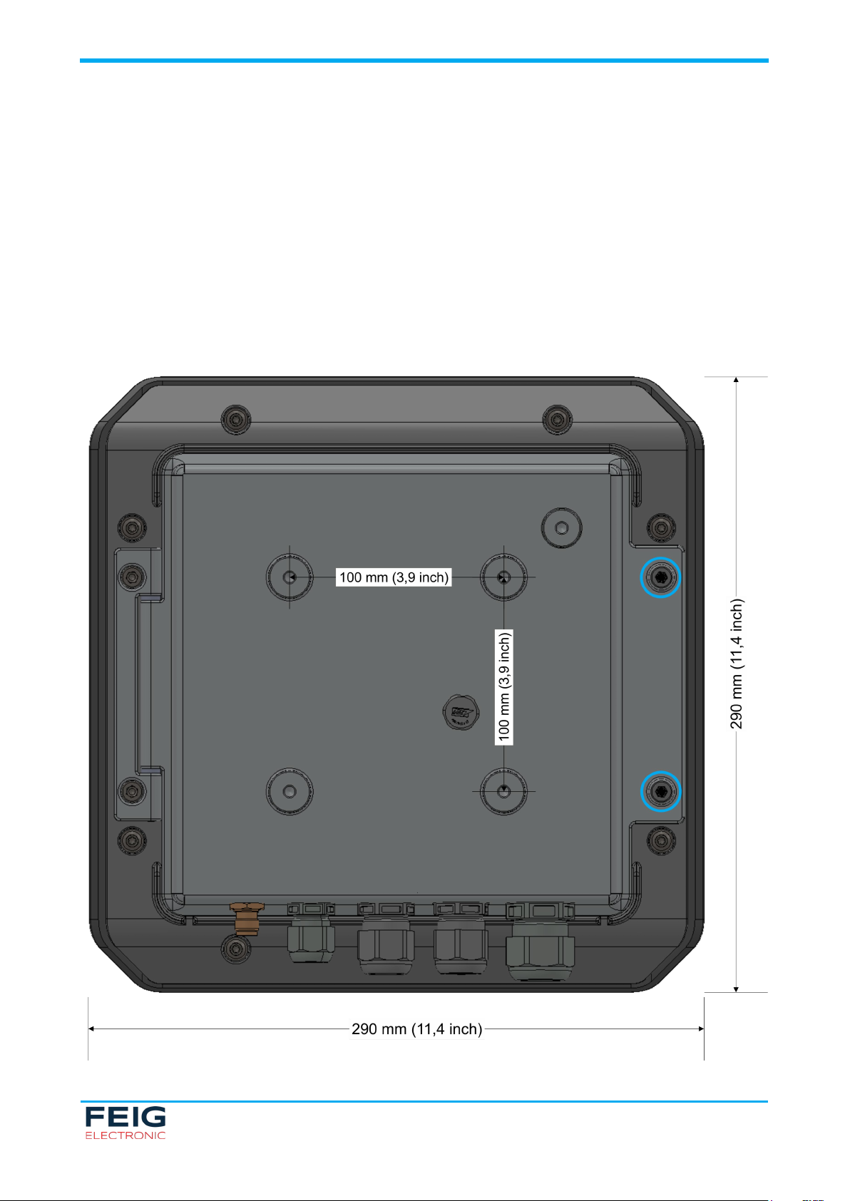
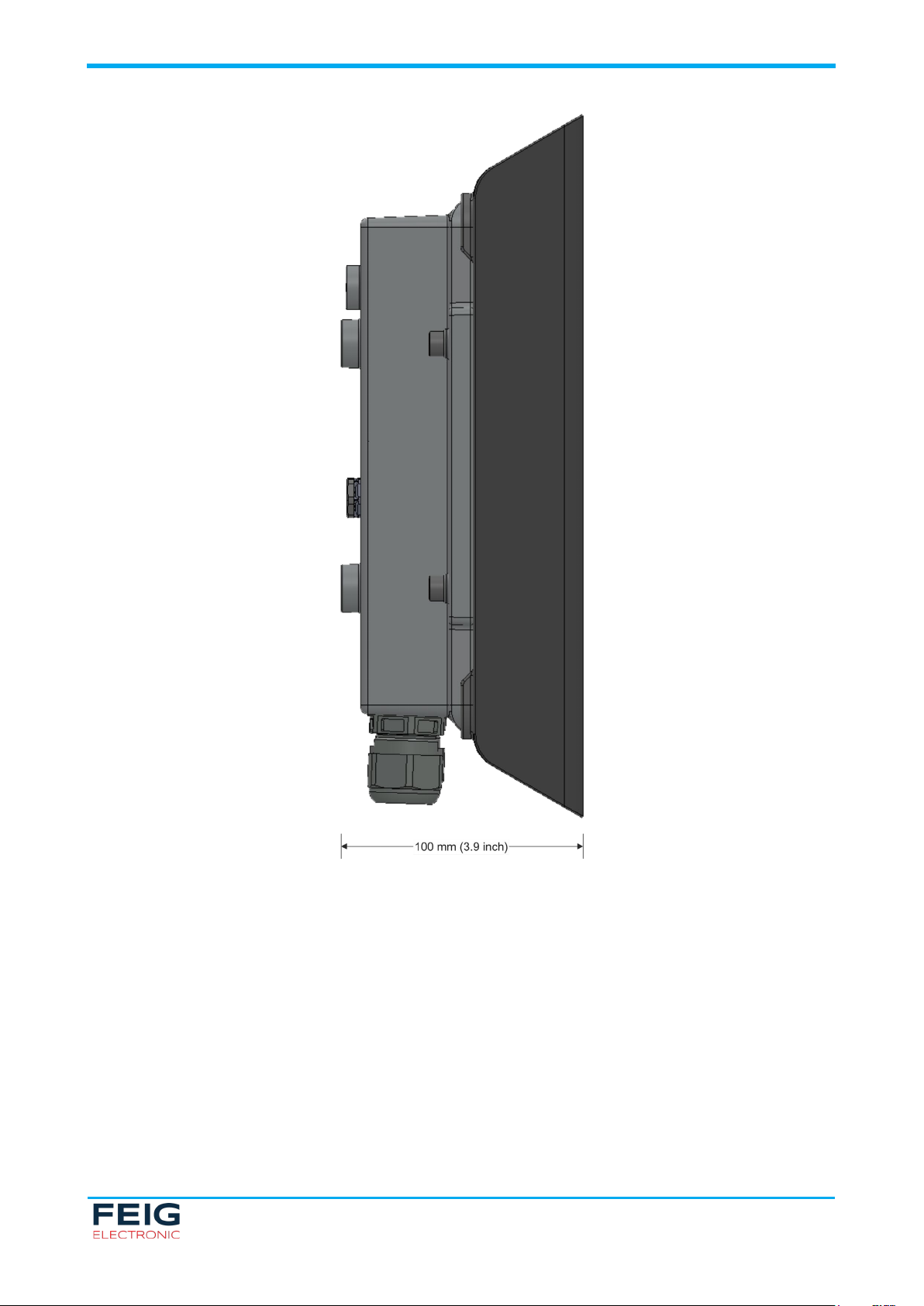
The ID MAX.U500i is designed to be mounted outdoors on a VESA bracket. The reader should be mounted
with the connections facing downwards to ensure tightness as shown below. Four holes for M5 screws are
provided on the backside of the housing for mounting on the VESA bracket. The screws used should have a
screw-in depth of maximum 8 mm. The housing can be opened by means of a hinge Therefore loosen the
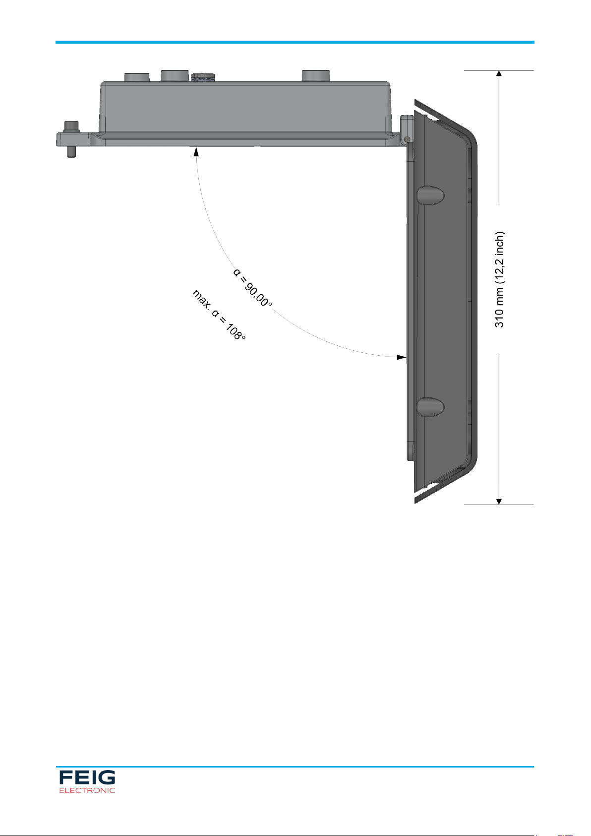
screws marked blue in Fig. 1 and swing away the front part of the reader. During installation, the dimensions
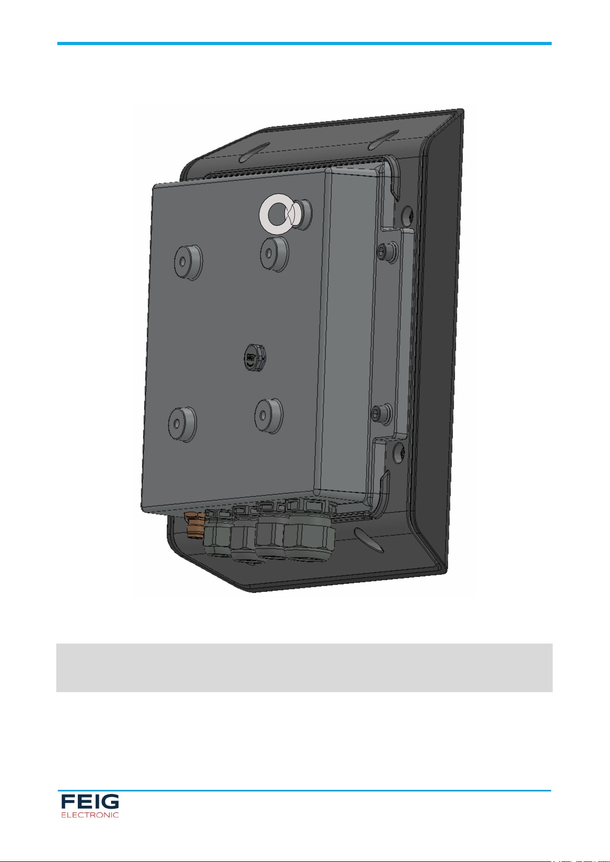
of the reader when opened should be taken into account (see Fig. 3). For secondary protection the reader
should be secured by means of an eye bolt (see Fig. 4), that should be fixed with screw locking varnish, and
e.g. a wire rope. The suitable accessory ID ANT.UEB-A can be purchased from FEIG ELECTRONIC.
Fig. 1: Dimensional drawing – back view
Page 9
IDENTIFICATION
ID MAX.U500i
4 Installation
Page 9 of 36
Fig. 2: Dimensional drawing – side view
Page 10
IDENTIFICATION
ID MAX.U500i
4 Installation
Page 10 of 36
Fig. 3: Dimensional drawing – top view: opened housing
Page 11
IDENTIFICATION
ID MAX.U500i
4 Installation
Page 11 of 36
Fig. 4: Secondary protection via eye bolt
NOTE:
FEIG ELECTRONIC GmbH strongly recommends to secure the reader against falling by means of an
eye bolt to prevent damage.
Page 12

IDENTIFICATION
ID MAX.U500i
5 Terminals
Page 12 of 36
Element
5 Terminals
Terminals
The cable connections are located on the lower side of the reader. Fig. 5 shows the arrangement of the
connectors and Table 1 gives an overview on the available connectors and interfaces. Table 2 lists the
available operating and display elements.
Connector Description
X1 10/100 Base-T Ethernet with RJ45
X2 Power Supply 12–24 V DC ±1 0 %
X4 Relay Outputs & Digital Outputs
X5 Digital Inputs
X6 USB Mini Interface
Operating /
Display
T1 Push Button for configuration reset or Teach-In
LED Status LEDs for service & maintenance
1 Buzzer
Fig. 5: Connection Overview
Table 1: Connection Terminals
Description
Mode
Table 2: Operating and Display Elements
Page 13

IDENTIFICATION
ID MAX.U500i
5 Terminals
Page 13 of 36
5.1 Antenna Connection
The TNC socket for connecting the external antenna is located on the lower side of the reader.
The maximum tightening torque for the TNC sockets is 0.69 Nm (6.11 lbf in).
Fig. 6: External antenna connection
CAUTION:
• Exceeding the tightening torque will destroy the antenna connection.
Page 14

IDENTIFICATION
ID MAX.U500i
5 Terminals
Page 14 of 36
Pin Number at
Connector X2
Abbreviation
Description
Conductor Cross Section
Validation Procedure
Fig. 7: Connector X2 pin assignment for power supply
5.2 Power Supply
5.2.1 Power Supply via Connector X2
The supply voltage of 12–24 V DC has to be connected to terminal X2.
1 GND Ground – suppy voltage
2 12–24 V Supply voltage 12–24 V DC ±10 %
Table 3: Pin assignment for power supply
CAUTION:
• The reader has to be supplied by a limited power supply according EN 62368-1 Chapter Q.1, or
with a NEC Class 2/LPS certified power supply.
• Each reader has to be supplied by a separate external power supply.
• Reversing the polarity of the supply voltage on X2 may destroy the device.
• External wiring for the power supply must fulfil the following norms/validation procedures:
from 0,5 mm² or bigger IEC 60332-1-2 and IEC 60332-1-3
smaller than 0,5 mm² IEC 60332-2-1 and IEC 60332-2-2
Table 4: Validation procedures for external wiring of the power supply
Page 15

IDENTIFICATION
ID MAX.U500i
5 Terminals
Page 15 of 36
Conductor Cross Section
Max. Cable Length for PoE
Fig. 8: LAN and PoE Connection
5.2.2 Power Supply via PoE (Power over Ethernet)
Optional the reader can be powered via the Ethernet interface on X1 with the use of a PoE „Power over
Ethernet“ power supply according to IEEE802.3at*, Class4 (30/25,5Watt). The DC supply can be achieved
via the free pins 4, 5 and 7, 8 (Midspan-Power). Also a “Phantom Powering” (Inline-Power) via the signal
pins 1, 2, 3 and 6 is possible. Depending on the conductor cross-section the following cable distances can
be used:
(CAT5…7)
0,4 mm² ~ 30 m
0,6 mm² ~ 70 m
Table 5: Max. cable length depending on the conductor cross section
* For detailed technical information regarding the 802.3at standard, please refer to the most recent edition of the
corresponding IEEE specification.
NOTE:
• It must be ensured that the reader is supplied with 42.5 V (48 V DC – cable losses) at least.
• An operation of an ID MAX.U500i via an external power supply and PoE at the same time is not
recommended and can cause interferences during operation.
• If the reader is supplied via PoE, no DC voltage can be provided at the connection for the external
antenna.
Page 16

IDENTIFICATION
ID MAX.U500i
5 Terminals
Page 16 of 36
Network
Address
Fig. 9: Ethernet connector
5.3 Ethernet Interface on Connector X1
The reader has an integrated 10/100 base-T network port for an RJ-45. Connection is made on X1 and has
an automatic “Crossover Detection” according to the 100BASE-T Standard.
With structured cabling STP CAT5 cables should be used. This ensures a reliable operation at 10 Mbps or
100 Mbps. The prerequisite for using TCP/IP protocol is that each device has a unique IP address on the
network. All readers have a factory set IP address. The transmission parameters can be configured as
required.
IP Address 192.168.10.10
Subnet Mask 255.255.0.0
Port 10001
DHCP OFF
Table 6: Standard factory configuration of the Ethernet connection
NOTE
The reader is equipped with a DHCP ready Ethernet interface.
Page 17

IDENTIFICATION
ID MAX.U500i
5 Terminals
Page 17 of 36
Pin Number at
Pin Assignment
Fig. 10: Connector X4 pin assignment for digital outputs
Fig. 11: internal and external wiring of the digital outputs
5.4 Digital Outputs on Connector X4
There are 2 digital outputs available on terminal X4. The transistor connection, collector and emitter, of the
optocoupler output is galvanically isolated from the reader electronic and routed to the outside at terminal X4
without internal additional circuitry. The output must therefore be supplied with an external voltage. Each
output is linked fixed with an antenna. Reading of a valid transponder on the internal antenna will affect the
digital output OPTO1-OUT, a valid reading on the external antenna will affect the digital output OPTO2-OUT.
Connector X4
1 OPTO2-OUT-C
2 OPTO2-OUT-E
3 OPTO1-OUT-C
4 OPTO1-OUT-E
Table 7: Pin Assignment X4 (Digital Outputs)
Page 18

IDENTIFICATION
ID MAX.U500i
5 Terminals
Page 18 of 36
Pin Number at
Pin Assignment
Fig. 12: Connector X4 pin assignment for relay outputs
Fig. 13: External wiring of the relay outputs
CAUTION:
• The outputs are designed for an input voltage of 12-24 V DC and an input current of max. 20 mA.
• Polarity reversal or overload of the outputs leads to their destruction!
• The output is only intended for switching resistive loads.
5.5 Relay Outputs on Connector X4
There are 2 relay outputs available at terminal X4 as normally open contacts. Each output is linked fixed with
an antenna. Reading of a valid transponder on the internal antenna will affect the relay REL1, a valid reading
on the external antenna will affect the relay REL2.
Connector X4
5 REL2-COM
6 REL2-NO
7 REL1-COM
8 REL1-NO
Table 8: Pin Assignment Relay Outputs REL1/REL2
Page 19

IDENTIFICATION
ID MAX.U500i
5 Terminals
Page 19 of 36
Pin Number at
Pin Assignment
Fig. 14: Connector X5 pin assignment for digital inputs
Fig. 15: External wiring of the digital inputs
CAUTION:
• The relay outputs are designed for max. 24 V DC / 2 A continuous load.
• The maximum switching current must not exceed 1 A.
• The relay outputs are intended for switching resistive loads only. In case an inductive load is
connected, the relay contacts must be protected by an external protective circuit.
5.6 Digital Inputs on Connector X5
There are 2 digital inputs available on X5. The optocouplers on X5 are galvanically isolated from the reader
electronics and must therefore be supplied with an external voltage.
Connector X5
1 OPTO2-IN –
2 OPTO2-IN +
3 OPTO1-IN –
4 OPTO1-IN +
Table 9: Pin Assignment X5 (digital inputs)
Page 20

IDENTIFICATION
ID MAX.U500i
5 Terminals
Page 20 of 36
The external resistor Rext is optional. When wiring the reader, make sure that the input voltage is at least
10.5 V.
CAUTION:
• The inputs are designed for an input voltage of 12-24 V DC and an input current of max. 20 mA.
• Polarity reversal or overload of the inputs leads to their destruction!
Page 21

IDENTIFICATION
ID MAX.U500i
5 Terminals
Page 21 of 36
Fig. 16: USB Mini interface for host communication
Fig. 17: USB On-The-Go adapter cable
5.7 USB Mini Interface on Connector X6
The reader is equipped with an integrated USB on-the-go interface. This can be used either to connect the
reader to a host system or, by means of a special on-the-go adapter cable, for connection of a USB memory
stick to the reader. In both cases, the connection is carried out via terminal X6. The pinout is standardized.
A standard shielded USB cable can be used to connect the reader to a host system. The data rate of the
reader is limited to 12 Mbit (USB full speed).
NOTE:
The length of the USB cable must not exceed 5 m (200 inch). It is not allowed to use longer cables.
5.7.1 USB Flash Drive Service Functions
Via an optionally available USB On-The-Go adapter cable, the interface can be converted to a USB host
interface. The adapter cable allows the connection of a USB memory stick to the reader. The USB memory
stick can be used to carry out various service functions, such as reading log and service data and uploading
a configuration file.
5.7.2 Reading of Log and Service Data
When connecting the USB flash drive during a running operation, the reader will create a subdirectory in the
root directory named after the device ID of the connected reader (see label on the back side of the reader)
and store device information such as firmware status and IP address in the INFO.LOG file within this
directory. If a corresponding file already exists for this reader the file will be updated with the new information
and the current date and time.
Page 22

IDENTIFICATION
ID MAX.U500i
5 Terminals
Page 22 of 36
In addition, the files ACTION.LOG and SERVICE.LOG with further information for service and maintenance
for the devices will be generated and stored on the USB flash drive. The function of the CONFIG.INI is
described in the following chapter.
As vehicle access control reader the ID MAX.U500i stores the event table in the same subdirectory. This
table contains the last recorded access control events and is stored as file EVENT.LOG in CSV format. An
existing file will be overwritten.
After plugging in the USB flash drive the green and red status LEDs will light up permanently. After
successful completion of the USB actions the red LED will go out and the green LED will start flashing again.
The USB flash drive can be disconnected from the device after the red status LED goes out. In case of an
error, the red status LED will start flashing until the USB flash drive is removed.
NOTE:
• After plugging in the USB flash drive the status LEDs of the reader should be observed.
• The USB flash drive may only be disconnected from the reader if the USB actions have been
completed!
• The USB on-the-go adapter cable may only be used in conjunction with a USB flash drive. When
used for a PC connection the reader may be destroyed or work with strange behavior!
5.7.3 Storing the Reader Configuration on a USB Flash Drive
When connecting the USB flash drive during running operation, the reader will store the readable
configuration as an editable and readable CSV file (CONFIG.INI) on the USB flash drive. This file will be
stored in the root directory of the USB flash drive for easy copying of the configuration (See chapter 5.7.4
Copying the Configuration onto a Reader (Config-Cloning) on page 23.). In addition, the same file will be
stored in a subdirectory named after the according device ID (see label on the back side of the reader).
Thereby it is possible to save the configuration files of several readers e.g. from one system/installation to
the same USB flash drive.
All non-locked configuration pages (CFG pages) including the interface parameters of a device will be copied
onto the USB flash drive. Password protected configuration pages will not be copied.
As vehicle access control reader the ID MAX.U500i stores the access control data (list of access rights, time
zone list and holiday table) within the file ACCESS.INI in the root directory of the USB flash drive. An existing
file will be overwritten.
After plugging in the USB flash drive the green and red status LEDs will light up permanently. After
successful completion of the USB actions the red LED will go out and the green LED will start flashing again.
The USB flash drive can be disconnected after the red status LED goes out.
In case of an error the red status LED will start flashing until the USB flash drive is removed.
NOTE:
• If a configuration file CONFIG.IN already exists in the main directory of the USB memory stick,
the old file will be overwritten.
• Password-protected configuration pages (see CFG 0) are not written to the USB memory stick.
No error message appears.
• After connecting the USB memory stick to the reader, the reader LEDs should be observed.
• The USB memory sticks may only be disconnected from the reader after the USB actions have
been completed.
Page 23

IDENTIFICATION
ID MAX.U500i
5 Terminals
Page 23 of 36
5.7.4 Copying the Configuration onto a Reader (Config-Cloning)
In order to copy the configurations and access control data stored in a USB flash drive to a reader, the
reader must be switched off before connecting the USB flash drive. After switching on the reader, the reader
will search for a USB flash drive during the boot process and copy the configuration and access control data
from the root directory to its memory.
It must be ensured that no configuration page (CFG page) is password protected in the reader. If
configuration pages are password protected, the configuration file will not be copied onto the reader. This
also applies if individual configuration parameters contain values out of the permissible range.
After successful completion of the USB actions the red status LED will go out and the green status LED will
start flashing again. After the red status LED went out the USB flash drive can be disconnected. In case of
an error the red status LED will start flashing until the USB flash drive is removed.
NOTE:
Connecting a USB flash drive during a running operation of the reader may overwrite an existing
configuration file stored on the USB memory stick (See chapter 5.7.4 Copying the Configuration onto
a Reader (Config-Cloning) on page 23.).
Page 24

IDENTIFICATION
ID MAX.U500i
6 Operating and Display Elements
Page 24 of 36
LED Label
Color
Description
antenna impedance error (unequal 50 Ω)
6 Operating and Display Elements
Operating and Display Elements
6.1 Status LEDs
The status LEDs are located under the push button T1 and the DIP switches S1.
Reader status LEDs
Res.
(yellow)
FLASH - - - While T1 is pushed and hold for 5 s to initiate a reset.
ON - - - Reader performs a reset (after pushing T1 for 5 s).
- - - FLASH Reader operates normally.
- - FLASH FLASH Reader receives a valid protocol from host.
- ON - FLASH RF Warning [0x84]
- FLASH
- FLASH FLASH FLASH Firmware transfer from host to reader.
Warning
(red)
(alternating)
COM
(yellow)
- FLASH
(sequentially)
RUN
(green)
(alternating)
Hardware warning; perform Reader Diagnostic [0x6E]
for further information.
Do not switch off the reader or disconnect the interface
cable during firmware transfer!
Table 10: Reader status LED overview
Description
Antenna status LEDs
green UHF power switched on
Ext. Ant.
blue transponder detected
red
green UHF power switched on
Int. Ant.
blue transponder detected
red
antenna impedance error (unequal 50 Ω)
Table 11: Antenna status LED overview
6.2 Push Button T1
By means of the pus h butto n T1 a com plete configur ati on reset c an be perf orme d. The pus h butt on is loc ated bet ween t he DIP s witches an d c onn ect or X1 on t he cir cui t bo ard. Fig ure X s ho ws th e p ositi on of t he p us h bu tton . T o pr ess the r es et b utt on T 1 it i s n ec ess ar y to o pen t he hous i ng b y me ans of t he hinge af ter loos eni ng t he scre ws X a nd X.
By means of the push button T1 the reader can be switched to Teach-In mode or a complete configuration
reset can be performed. The push button is located between the DIP switches and connector X1 on the
circuit board. Fig. X shows the position of the push button. To press the button T1 it is necessary to open the
housing by means of the hinge after loosening the screws.
6.2.1 Teach-In Mode
The Teach-In Mode can be used for easy programming of new authorized transponders if the configuration
software myAXXESS Manager is not or cannot be used. In Teach-In Mode it is not possible to configure time
restrictions for the different users. This means transponders registered via Teach-In Mode are valid and have
access 24/7.
Activation of the Teach-In Mode:
• Activate the Teach-In Mode by briefly pressing the push button T1 twice within a short time
Page 25

IDENTIFICATION
ID MAX.U500i
6 Operating and Display Elements
Page 25 of 36
• As long as the Teach-In Mode is active, the yellow LED (V4) is switched on. Access will be granted
immediately to all transponders which are read and stored in the reader during this time.
• At first the new authorizations will be stored temporarily in the reader. If the Teach-In Mode is disabled
again by pressing the push button T1 briefly twice again, all new authorizations will be stored
permanently in the reader. These transponders will now have permanent access. Authorizations stored
permanently in the reader will still be available if the system was powered off, while temporarily stored
authorizations will be lost in the event of a power loss.
NOTE:
• In case of power down during activated Teach-In Mode all temporarily stored authorizations are
lost and have to be read again.
• In case of power down during deactivation of the Teach-In Mode (after pressing the push button
T1 twice within short time the second time) all authorizations stored in the reader may be lost.
A stable power supply must be ensured!
• The use of the Teach-In Mode is only recommended for small systems with a manageable
number of authorized transponders and users.
• It is possible to import access control data to the reader by connecting a USB flash drive.
• Please note that in some vehicles RFID transponders may already be installed by the
manufacturer or other system provider. These transponders could also be detected by the reader
in Teach-In Mode.
6.2.2 Configuration Reset
By means of the push button T1 a complete configuration reset can be performed. Push the button for at
least 5 s until the reset LED below the button is switched on continuously. After releasing the push button the
reader performs a restart.
During a complete configuration reset all parameters of the reader will be reset back to factory default and
need to be configured again. Access authorizations stored in the access control reader are not affected.
6.3 Buzzer
The buzzer is located above the digital inputs on terminal X5. It is used to notify the service personnel of
events during maintenance and service.
6.4 Reader Power Adjustment
In order to achieve high reading ranges, it is necessary to set the reader output power to the highest allowed
level. This depends on the reader type used (EU/FCC) and the applicable radio regulations at the installation
site. The output power is adjustable in 100 mW steps from 0.1 W to 1 W.
NOTE:
• Both in the EU version and in the FCC version of the reader the output power of the internal
antenna must not exceed 0.8 W.
• The admissible max. output power is 2 W e.r.p. for EU versions and 4 W e.i.r.p. for FCC versions.
The output power depends on the antenna gain. For calculating the reader output power the
Excel file “Calc-RF-Power.xls” is available from FEIG ELECTRONIC GmbH. If a circular polarized
antenna is used the antenna gain [dBic] can be reduced by 3 dB. If using a linear polarized
antenna the max. antenna gain [dBi] must be used.
Page 26

IDENTIFICATION
ID MAX.U500i
7 Positioning of the Antenna
Page 26 of 36
Fig. 18: Angle of the antenna to the roadway
7 Positioning of the Antenna
Positioning of th e Antenna
h
It is recommended to mount the antenna at the side of the roadway on a mast. The mounting height depends
on the type of vehicle that should be detected.
Vehicle Type Recommended Mounting Height
cars only approx. 2.0 m
lorries and busses only approx. 2.5 m
cars, lorries & busses approx. 2.0 m
Table 12: Recommended mounting height depending on vehicle type
The antenna should be mounted at an angle of approx. 45° to the roadway.
If the vehicle access control reader is used to control a barrier, the antenna should be mounted at a sufficient
distance in front of the barrier. The distance depends on the permitted or desired speed of the vehicles. In
this way, it is possible for the individual vehicles to access the respective area smoothly and without delay.
In case an access from two different directions is possible, or in case of difficult environmental conditions at
the point of installation, a second additional antenna can be installed and connected to the reader.
Page 27

IDENTIFICATION
ID MAX.U500i
7 Positioning of the Antenna
Page 27 of 36
Fig. 19: Typical vehicle access control application
Fig. 20: Positioning of the antenna
Page 28

IDENTIFICATION
ID MAX.U500i
8 Mounting of the Transponder
Page 28 of 36
8 Mounting of the Transponder
Mounting of the Tr ansponder
Passive UHF transponders operating at a frequency of 865–928 MHz are used for identification of vehicles
with the vehicle access control reader. To ensure a reliable identification of the transponder and to reduce
interfering environmental influences such as metal, it is recommended to mount the transponder label in the
middle of the windshield behind the interior mirror. The transponders optionally available from
FEIG ELECTRONIC GmbH are self-adhesive labels. To mount these transponders, simply remove the
protective foil on the back and attach the transponder to the windshield.
Before mounting the transponder the windshield should be thoroughly cleaned to ensure optimum adhesion
of the self-adhesive labels.
Vehicles with integrated windshield heating require special mounting of the transponder. In this case the
transponder should be mounted in an area of the windshield where no wires of the windshield heating run.
Usually corresponding information can be found in the manual of the vehicle. Otherwise, the information can
be obtained from the manufacturer.
Vehicles with tinted, vaporized or metallized windshields may occasionally experience problems identifying
the transponder. These vehicles usually also have an area in the windshield where no coating has been
applied to enable radio systems to communicate with the exterior. If possible the transponder should be
mounted at such an uncoated position. The position of the uncoated area can usually be found in the manual
of the vehicle or can be obtained from the manufacturer.
Fig. 21: Positioning of transponders on different windshield types
Page 29

IDENTIFICATION
ID MAX.U500i
9 Technical Data
Page 29 of 36
M
9 Technical Data
Technical D ata
EC HANICAL DATA
Housing Plastic (ASA-PC)
Aluminum
Dimension (W x H x D) 290 mm x 290 mm x 100 mm
(11.4“ x 11.4“ x 3.9“)
Weight 2800 g
Mounting VESA FDMI MIS-D 100 mm x 100 mm
Protection Class IP 65
Colour Anthracite, translucent
ELE C TRIC AL DATA
Power Supply 12–24 V DC (± 10 %), PoE+
Current Consumption typical 16 W (22 W with PoE+)
Operating Frequency
• EU Reader
• FCC Reader
Output Power 100 mW to max. 1 W
Antenna Connection 1 x R-TNC jack (50 Ω)
RF Diagnostic RF channel monitoring,
Outputs
• 2 x Optocoupler
• 2 x Relay
Inputs
• 2 x Optocoupler
865 MHz to 868 MHz
902 MHz to 928 MHz
configurable in steps of 100 mW
(Reverse-TNC)
Antenna SWR control,
Internal Overheating Protection
max. 24 V DC / 20 mA
max. 24 V DC / 1 A switching current, 2 A permanent
current
max. 24 V DC / 20 mA
CAUTION:
Overheating of the device may result in performance losses. It is recommended to activate the RF of
the reader only if there is a transponder in the detection range of an antenna.
Interfaces Ethernet, USB (OTG)
Protocol Modes ISO Host Mode, Access Mode
FUNC TIONAL P ROP ERTIES
Supported Transponder Types EPC Class 1 Gen 2
EPC Class 1 Gen 2 V2
ISO 18000-6-C
ISO 18000-63
Indicators Signal light with red/green/blue
10 LEDs to indicate operation and antenna state
Buzzer
Further Features Anti-Collision,
output of RSSI values and phase angle,
battery-assisted Real Time Clock,
supports encrypted transponder communication,
Secure Key Storage,
Config Cloning Function
Page 30

IDENTIFICATION
ID MAX.U500i
9 Technical Data
Page 30 of 36
ENVIRONMENTAL CO NDITIONS
Temperature Range
• Operation
• Storage
-25 °C to 55 °C
-25 °C to 85 °C
Humidity 5 % to 95 % (non-condensing)
Vibration EN 60068-2-6
10 Hz to 150 Hz: 0,075 mm / 1 g
Shock EN 60068-2-27
Acceleration: 30 g
AP P LICAB LE S TAN DAR DS
Radio Regulation
• Europe
• USA
• Canada
• India
EN 302 208
FCC 47 CFR Part 15
IC RSS-GEN, RSS-210
BIS IS 13252 Part 1
EMC EN 301 489
Safety
• Low Voltage
• Human Exposure
EN 62368
EN 50364
Others RoHS, WEEE
Page 31

IDENTIFICATION
ID MAX.U500i
10 Radio Approvals
Page 31 of 36
10 Radio Approvals
Radio Approvals
10.1 Europe (CE)
Hereby FEIG ELECTRONIC GmbH declares that the radio equipment type ID MAX.U500i is in compliance
with Directive 2014/53/EU. The full text of the EU declaration of conformity is available at the following
internet address:
http://www.feig.de/en/downloads-support/declarations-of-conformity.html
Performance Classification according to ETSI EN 301 489: Class 2
Page 32

IDENTIFICATION
ID MAX.U500i
10 Radio Approvals
Page 32 of 36
10.2 USA (FCC) and Canada (IC)
10.2.1 USA (FCC) and Canada (IC) Warning Notices
Product name: ID MAX.U500i-FCC
FCC ID:
IC:
Notice for USA and
Canada
This device complies with Part 15 of the FCC Rules and with ISED licence-exempt RSS
standard(s).
Operation is subject to the following two conditions.
(1) this device may not cause harmful interference, and
(2) this device must accept any interference received,
including interference that may cause undesired operation.
Unauthorized modifications may void the authority granted under Federal communications
Commission Rules permitting the operation of this device.
This equipment has been tested and found to comply with the limits for a Class A digital
device, pursuant to Part 15 of the FCC Rules. These limits are designed to provide reasonable
protection against harmful interference when the equipment is operated in a commercial
environment. This equipment generates, uses, and can radiate radio frequency energy and, if
not installed and used in accordance with the instruction manual, may cause harmful
interference to radio communications. Operation of this equipment in a residential area is likely
to cause harmful interference in which case the user will be required to correct the interference
at his own expense.
L’émetteur/récepteur exempt de licence contenu dans le présent appareil est conforme aux
CNR d'Innovation, Sciences et Développement économique Canada applicables aux appareils
radio exempts de licence. L'exploitation est autorisée aux deux conditions suivantes :
(1) l'appareil ne doit pas produire de brouillage ;
(2) l'appareil doit accepter tout brouillage radioélectrique subi, même si le brouillage est
susceptible d'en compromettre le fonctionnement.
PJMLRU500i
6633A-LRU500i
NOTE:
Changes or modifications made to this equipment not expressly approved by
FEIG ELECTRONIC GmbH may void the FCC authorization to operate this equipment.
10.2.2 Installation with FCC/IC Approval
To comply with FCC Part 15 Rules in the United States / IC Radio Standards in Canada, the system must be
professionally installed to ensure compliance with the FCC Part 15 certification / IC certification. It is the
responsibility of the operator and professional installer to ensure that only certified systems are deployed in
the United States / Canada.
The system is intended for industrial and commercial use and requires professional installation. The device
and the software required for commissioning and operation are only available from FEIG ELECTRONIC or its
distributors.
Installation, commissioning, configuration and operation require qualified knowledge of high-frequency and
RFID technology due to its complexity. The connections used are from the industrial sector.
Page 33

IDENTIFICATION
ID MAX.U500i
10 Radio Approvals
Page 33 of 36
Antenna
Lin. Gain
Cable Attenuation
Cable Length*
10.2.3 Label Information
The following information must be placed at the outer side of the housing in which the reader is mounted.
Contains FCC ID: PJMLRU500i
Contains IC: 6633A-LRU500i
10.2.4 Antennas Approved in the USA (FCC) and Canada (IC)
This radio transmitter (identify the device by certification number, or model number if Category II) has been
approved by Industry Canada to operate with the antenna types listed below with maximum permission gain
and required antenna impedance for each antenna type indicated. Antenna types, not included in this list,
having a gain greater than the maximum gain indicated for that type, are strictly prohibited for use with this
device.
The antennas used for this transmitter must be installed to provide a separation distance of at least 23 cm
from all persons and must not be located or operating in conjunction with any other antenna or transmitter,
except as listed for this product's certification.
Le présent émetteur radio (identifier le dispositif par son numéro de certification ou son numéro de modèle
s’il fait partie du matériel de catégorie I) a été approuvé par Industrie Canada pour fonctionner avec les types
d’antenne ’énoncé ci-dessus et ayant un gain admissible maximal et l’impédance requise pour chaque type
d’antenne. Les types d’antenne non inclus dans cette liste, ou dont le gain est supérieur au gain maximal
indiqué, sont strictement interdits pour l’exploitation de l’émetteur.
Les antennes utilisées pour cet émetteur doit être installé pour fournir une distance de séparation d'au moins
23 cm de toutes les personnes et ne doit pas être situé ou opérant en conjonction avec une autre antenne
ou un autre émetteur, sauf dans les cas énumérés à la certification de ce produit.
Following antennas are approved by FCC according FCC Part 15 and IC Canada according RS210:
• ID ISC.ANT.U290/290 (8.5 dBic)
• ID ISC.ANR.U580/290 (11.5 dBic)
In order not to exceed the limit value of 4 W EIRP (Effective Isotopic Radiated Power), the cable attenuation
must be sufficiently high at 1 W transmission power at the antenna connection, according to the following
table:
[dB] [dB] [m]
ID ANT.U290/290 6.6 0.6 2
ID ANT.U580/290 9.5 3.5 12
* For cables of the type H155 with an attenuation of 0.3 dB per meter.
In general, the required cable attenuation for a given output power P of e.g. 30 dBm, corresponding 1 W, is
calculated as follows:
Cable Attenuation [dB] = P [dB] - 36 + Lin. Gain [DB]
Page 34

IDENTIFICATION
ID MAX.U500i
Annex A: Radio Approvals
Page 34 of 36
Annex A: Accessories
For the ID MAX.U500i following optional accessories are available:
Order Number Article Description
2557.000.00 ID NET.24V-B
2558.000.00 ID CAB.NET.24V-B-EU Power Supply Unit Cable with continental Europe plug
2559.000.000 ID CAB.NET.24V-B-GB Power Supply Unit Cable with UK plug
2560.000.00 ID CAB.NET.24V-B-US Power Supply Unit Cable with US plug
5255.000.00
5243.001.00
5243.002.00
5335.000.00
ID ANT.C2-C UHF Antenna Cable
ID ANT.C6-C UHF Antenna Cable
ID MS.VESA100-A
Mounting Set
R-TNC/TNC 2 m
R-TNC/TNC 6 m
ID ANT.C6-x UHF Antenna
Extension Cable TNC/TNC 6 m
EU: 5236.000.00 ID ANT.U290/290
FCC: 5236.000.10
EU: 5238.000.00
FCC: 5238.000.10
UHF wide-range antenna 65°
circular
ID ANT.U580/290
UHF wide-range antenna 30°
circular
5254.000.00 ID ANT.UEB-A Eye Bolt
4104.000.00 ID CPR.USB/OTG
3271.000.00
ID CTF-U
Windshield Transponder
24 V Power Supply Unit; Supply Cable available separately
for EU, GB and US (not included)
Mast and wall mounting set with VESA100 receptacle for
pipe diameters of 1'' - 3'' (approx. 2.5 cm to 7.6 cm)
H155 Coaxial cable for UHF antennas with TNC socket and
UHF reader with R-TNC connector
Connection type: Connector R-TNC / Connector TNC
Length: 2 m
H155 Coaxial cable for UHF antennas with TNC socket and
UHF reader with R-TNC connector
Connection type: Connector R-TNC / Connector TNC
Length: 6 m
H155 Coaxial extension cable for UHF antennas with TNC
socket
Connection type: TNC female / TNC male
Length: ca. 6 m
Robust UHF antenna for connection to stationary UHF
readers
Connection: TNC socket
Robust UHF antenna for connection to stationary UHF
readers
Optimized beam angle, increased antenna gain
Connection: TNC socket
M6 eye bolt for fall protection/secondary protection, PU: 10
pieces
4 GB USB memory stick with OTG adapter cable
(USB mini to USB A)
Self-adhesive, passive UHF transponder for mounting in
windshield, PU: 10 pieces
Page 35

IDENTIFICATION
ID MAX.U500i
List of Tables
Page 35 of 36
List of Tables
List of Tables
Table 1: Connection Terminals ........................................................................................................................ 12
Table 2: Operating and Display Elements ....................................................................................................... 12
Table 3: Pin assignment for power supply ....................................................................................................... 14
Table 4: Validation procedures for external wiring of the power supply .......................................................... 14
Table 5: Max. cable length depending on the conductor cross section .......................................................... 15
Table 6: Standard factory configuration of the Ethernet connection ............................................................... 16
Table 7: Pin Assignment X4 (Digital Outputs) ................................................................................................. 17
Table 8: Pin Assignment Relay Outputs REL1/REL2 ...................................................................................... 18
Table 9: Pin Assignment X5 (digital inputs) .................................................................................................... 19
Table 10: Reader status LED overview ........................................................................................................... 24
Table 11: Antenna status LED overview ......................................................................................................... 24
Table 12: Recommended mounting height depending on vehicle type .......................................................... 26
Page 36

IDENTIFICATION
ID MAX.U500i
List of Figures
Page 36 of 36
List of Figures
List of Figures
Fig. 1: Dimensional drawing – back view .......................................................................................................... 8
Fig. 2: Dimensional drawing – side view ........................................................................................................... 9
Fig. 3: Dimensional drawing – top view: opened housing ............................................................................... 10
Fig. 4: Secondary protection via eye bolt ........................................................................................................ 11
Fig. 5: Connection Overview ........................................................................................................................... 12
Fig. 6: External antenna connection ................................................................................................................ 13
Fig. 7: Connector X2 pin assignment for power supply ................................................................................... 14
Fig. 8: LAN and PoE Connection ..................................................................................................................... 15
Fig. 9: Ethernet connector ............................................................................................................................... 16
Fig. 10: Connector X4 pin assignment for digital outputs ................................................................................ 17
Fig. 11: internal and external wiring of the digital outputs ............................................................................... 17
Fig. 12: Connector X4 pin assignment for relay outputs ................................................................................. 18
Fig. 13: External wiring of the relay outputs .................................................................................................... 18
Fig. 14: Connector X5 pin assignment for digital inputs .................................................................................. 19
Fig. 15: External wiring of the digital inputs ..................................................................................................... 19
Fig. 16: USB Mini interface for host communication ....................................................................................... 21
Fig. 17: USB On-The-Go adapter cable .......................................................................................................... 21
Fig. 18: Angle of the antenna to the roadway .................................................................................................. 26
Fig. 19: Typical vehicle access control application .......................................................................................... 27
Fig. 20: Positioning of the antenna .................................................................................................................. 27
Fig. 21: Positioning of transponders on different windshield types ................................................................. 28
 Loading...