

Feig Electronic ID ISC.ANTH200/200, ID ISC.ANTH200/200-TJS, ID ISC.ANTH200/200-A Series Manual
Page 1

State: 2010-03-01
Vers. no.: 1.10
Annex no. 12
Antenna Description
m. dudde hochfrequenz-technik Rottland 5a D-51429 Bergisch Gladbach/ Germany Tel. +49 2207-96890 Fax +49 2207 968920
Page 2
MONTAGE
®
OBID i-scan
INSTALLATION
ID ISC.ANTH200/200-A
ID ISC.ANTH200/200-TJS
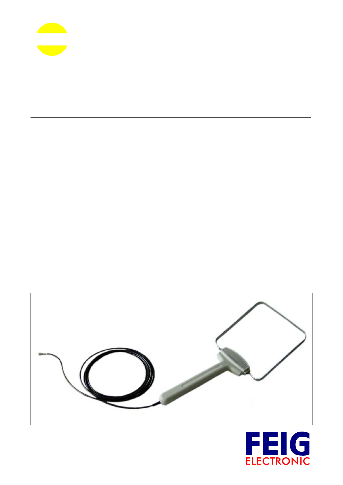
Allgemeine Leistungsmerkmale General Deskription
Vielen Dank, dass Sie sich für den Kauf der Antenne
ID ISC.ANTH200/200 entschieden haben.
ID ISC.ANTH200/200 ist eine Single Loop Antenne
und wurde als eine Sende- und Empfangsantenne
für die iscan Midrange Reader mit externen
Antennenanschluss optimiert. Mit der vom Reader
abgegebenen Sendeleistung von 2 W (max.
Sendeleistung der Antenne) und einem Label
(45 x 76 mm
ist eine Lesereichweite von 30 - 40cm bei paralleler
Labelorientierung zur Antenne möglich. Der Betrieb
an anderen Readern mit 13,56 MHz Sendefrequenz
und 50 Ω Ausgangsimpedanz ist ebenfalls möglich.
Die maximale Reichweite wird über der Mitte der
Antennenfläche erreicht. Die Vorzugsrichtung eines
Smart Label ist parallel zur Antennenfläche.
Die Antenne wird im Werk auf die Impedanz von
50 Ω abgestimmt. Der Betrieb in einer metallenen
Umgebung ist ebenso möglich!
Die Antenne kann sowohl für die Güter- als auch zur
Personenerkennung verwendet werden.
2
Größe; Labelempfindlichkeit 75 mA/m)
Thank you for choosing the ID ISC.ANTH200/200
antenna.
ID ISC.ANTH200/200 is a single loop antenna and
has been optimized as a sending and receiver
antenna for the iscan midrange Readers with
external antenna connection. Using the transmitting
power of the Reader of 2 W (max. transmission
power of the antenna) and a label (45 x 76 mm
size; label sensitivity 75 mA/m) a read range of 30-40
cm is possible with the label oriented parallel to the
antenna. Operation with other Readers having a
transmission frequency of 13.56 MHz and 50 Ω
output impedance is also possible. The maximum
range is achieved over the middle of the antenna
area. The preferred orientation of a smart label is
parallel to the antenna area.
The antenna is factory tuned to an impedance of
50 Ω. Operation in metallic surroundings is also
possible!
The antenna can be used for either product or person detection.
2
in
M60600-0de-ID-B.doc / 2006-08-10
Page 3
OBID i-scan
®
MONTAGE / INSTALLATION ID ISC.ANTH200/200
Technische Daten Technical Data
Gehäuse / housing ABS / UL 94 HB
Abmessungen (B x H x T ) / dimensions ( W x H x D )
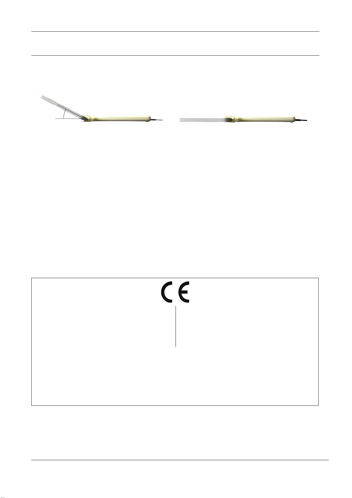
25°
ID ISC.ANTH200/200-A
approx. 460 x 200 x 120 mm
3
ID ISC.ANTH200/200-TJS
approx. 460 x 200 x 25 mm
Gewicht / weight approx. 0.35 kg
Schutzart / protection class IP 20
Temperaturbereich / temperature range
• Betrieb / operation
• Lagerung / storage
-0 °C to +55 °C
-25 °C to +85 °C
relative Luftfeuchte / relative air humidity 95 % (non-condensing)
Betriebsfrequenz / operating frequency 13.56 MHz
Anschlusskabel / connecting cable
Antennenanschluss / connection
RG58; 50 Ω; 3.6 m
SMA – plug (50 Ω)
max. Sendeleistung / max. transmitting power 2 W
3
Das Gerät entspricht bei bestimmungsgemäßer Verwendung den Anforderungen der EU-Richtline
89/336/EEC (Electromagnetic Compatibility (EMC).
When properly used this radio equipment conforms
to the essential requirements of Article 3 and the
other relevant provisions of the R&TTE Directive
1999/5/EC of March 99.
Electromagnetic compatibility (EMC) – Generic emission standard;
EN 61000-6-3:2001
Part 6-3: Generic standards – Emission standard for residential
residential, commercial and light industry
Electromagnetic compatibility (EMC) –
EN 61000-6-2:2001
Part 6-2: Generic standards – Immunity of industrial environments
FEIG ELECTRONIC GmbH M60600-0de-ID-B.doc
Page 4

OBID i-scan
®
MONTAGE / INSTALLATION ID ISC.ANTH200/200
Sicherheits- und Warnhinweise Safety Instructions
• Das Gerät darf nur für den vom Hersteller
vorgesehenen Zweck verwendet werden.
• Die Bedienungsanleitung ist zugriffsfähig
aufzubewahren und jedem Benutzer auszuhändigen.
• Unzulässige Veränderungen und die Ver-
wendung von Ersatzteilen und Zusatzeinrichtungen, die nicht vom Hersteller des
Gerätes verkauft oder empfohlen werden,
können Brände, elektrische Schläge und
Verletzungen verursachen. Solche Maßnahmen führen daher zu einem Ausschluss
der Haftung und der Hersteller übernimmt
keine Gewährleistung.
• Für das Gerät gelten die Gewährleistungs-
bestimmungen des Herstellers in der zum
Zeitpunkt des Kaufs gültigen Fassung. Für
eine ungeeignete, falsche manuelle oder
automatische Einstellung von Parametern für
ein Gerät bzw. ungeeignete Verwendung
eines Gerätes wird keine Haftung
übernommen.
• Reparaturen dürfen nur vom Hersteller durch-
geführt werden.
• Anschluss-, Inbetriebnahme-, Wartungs-, und
sonstige Arbeiten am Gerät dürfen nur von
Fachkräften mit einschlägiger Ausbildung
erfolgen.
• Alle Arbeiten am Gerät und dessen
Aufstellung müssen in Übereinstimmung mit
den nationalen elektrischen Bestimmungen
und den örtlichen Vorschriften durchgeführt
werden.
• Bei Arbeiten an dem Gerät müssen die
jeweils gültigen Sicherheitsvorschriften
beachtet werden.
• Besonderer Hinweis für
Träger von Herzschrittmachern:
Obwohl dieses Gerät die zulässigen Grenzwerte für elektromagnetische Felder nicht
überschreitet, sollten Sie einen Mindestabstand von 25 cm zwischen dem Gerät und
Ihrem Herzschrittmacher einhalten und sich
nicht für längere Zeit in unmittelbarer Nähe
des Geräts bzw. der Antenne aufhalten.
• The device may only be used for the intended
purpose designed by for the manufacturer.
• The operation manual should be conveniently
kept available at all times for each user.
• Unauthorized changes and the use of spare
parts and additional devices which have not
been sold or recommended by the
manufacturer may cause fire, electric shocks
or injuries. Such unauthorized measures
shall exclude any liability by the
manufacturer.
• The liability-prescriptions of the manufacturer
in the issue valid at the time of purchase are
valid for the device. The manufacturer shall
not be held legally responsible for
inaccuracies, errors, or omissions in the
manual or automatically set parameters for a
device or for an incorrect application of a
device.
• Repairs may only be executed by the
manufacturer.
• Installation, operation, and maintenance
procedures should only be carried out by
qualified personnel.
• Use of the device and its installation must be
in accordance with national legal
requirements and local electrical codes .
• When working on devices the valid safety
regulations must be observed.
• Special advice for
carriers of cardiac pacemakers:
Although this device doesn't exceed the valid
limits for electromagnetic fields you should
keep a minimum distance of 25 cm between
the device and your cardiac pacemaker and
not stay in an immediate proximity of the device respective the antenna for some time.
FEIG ELECTRONIC GmbH M60600-0de-ID-B.doc
Page 5
OBID i-scan
®
MONTAGE / INSTALLATION ID ISC.ANTH200/200
Zusätzliche Hinweise Additional Information
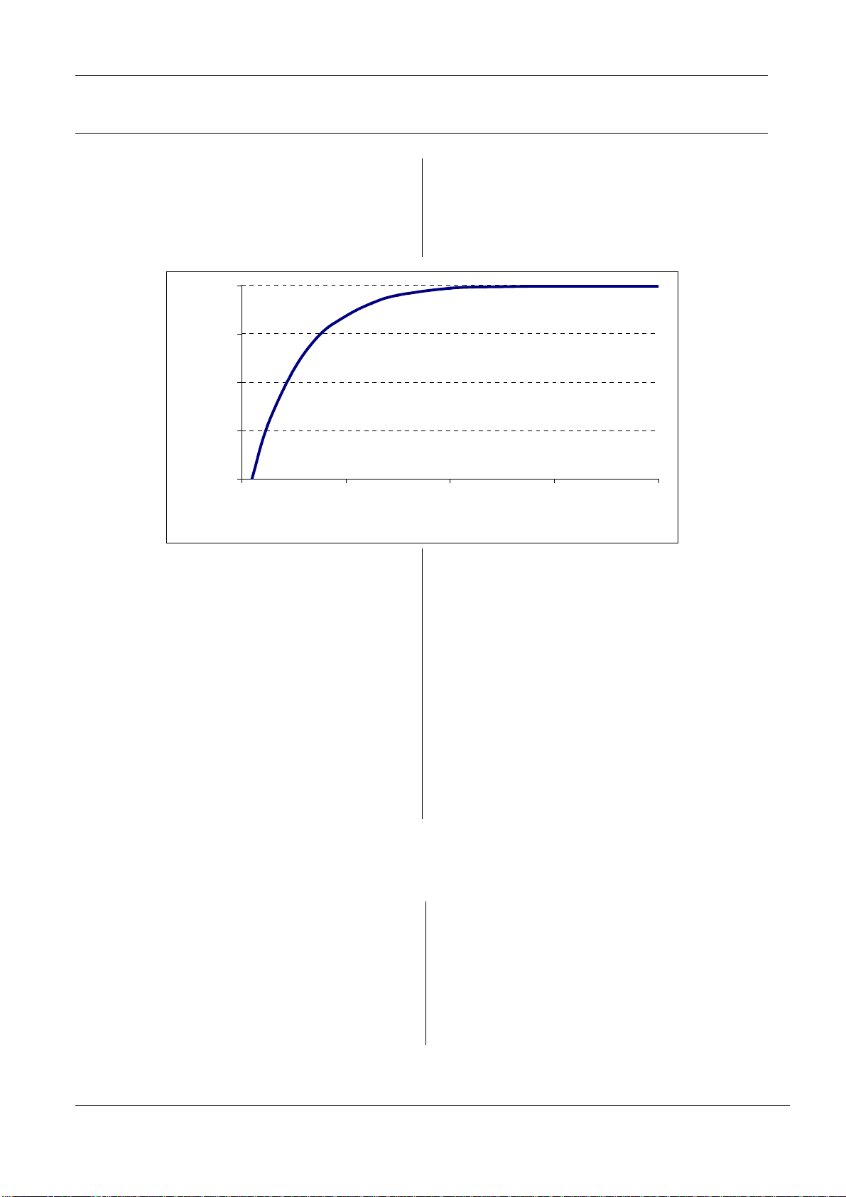
- Metall in der Nähe des Antennenrahmens beein-
trächtigt die Lesereichweite der Antenne. Ab einem Abstand kleiner 10 cm muss mit erheblichen
Einbußen in der Lesereichweite gerechnet werden.
100%
75%
50%
reading range
25%
0%
0 10203040
distance to metall / cm
- Wird im Betrieb der Antennenbügel angefasst,
kann es zu erheblichen Reichweiteneinbußen
kommen. Die Antenne sollte nur am dafür vorgesehenen Griff angefasst werden.
Metal in the vicinity of the antenna frame affects the
read range of the antenna. At a distance of less than
10 cm significant reduction in the read range will result.
- Touching the antenna loop during operation will
result in significant reduction of the read range.
The antenna should be grasped only by the
holder provided.
- Beim Betrieb ist darauf zu achten, dass das
Kabel von der Antenne weggeführt wird. Befindet
sich das Anschlusskabel im Empfangsbereich
der Antenne kann dies zu Störungen führen.
- Nach Montage kann die korrekte Funktion der
Antenne mit Hilfe eines Transponders überprüft
werden. Bei einem Mindestabstand von 10 cm zu
Metall ist mit einem 45 x 76 mm
2
großem
Transponder mit paralleler Ausrichtung zu Antenne eine Reichweite von mind. 30 cm senk-
- When operating, be sure that the antenna cable
is routed away from the antenna. Locating the
cable in the receiving range of the antenna will
result in faulty operation.
- After installation, check for correct function of the
antenna using a transponder. At a minimum distance of 10 cm from metal and a 45 x 76 mm
transponder aligned parallel to the antenna, a
range of min. 30 cm vertically from the center of
the antenna can be achieved.
recht über der Mitte der Antenne zu erreichen.
© Copyright 2006 by FEIG ELECTRONIC GmbH • Lange Straße 4 • D-35781 Weilburg-Waldhausen
Liefermöglichkeiten und technische Änderungen
vorbehalten.
FEIG ELECTRONIC GmbH übernimmt keine Gewährleistung dafür, dass die in diesem Dokument enthaltenden Informationen frei von fremden Schutzrechten sind. FEIG
ELECTRONIC GmbH erteilt mit diesem Dokument keine
Lizenzen auf eigene oder fremde Patente oder andere
Schutzrechte.
Data and design subject to change without notice. Supply
subject to availability.
FEIG ELECTRONIC GmbH assumes no responsibility for
the use of any information contained in this manual and
makes no representation that they free of patent infringement. FEIG ELECTRONIC GmbH does not convey any license under its patent rights nor the rights of others.
2
OBID® and OBID i-scan® are registered trademarks of FEIG ELECTRONIC GmbH.
FEIG ELECTRONIC GmbH M60600-0de-ID-B.doc
Page 6
MONTAGE
INSTALLATION
final
public (B)
2011-05-30
M90401-2de-ID-B.doc
OBID i-scan®
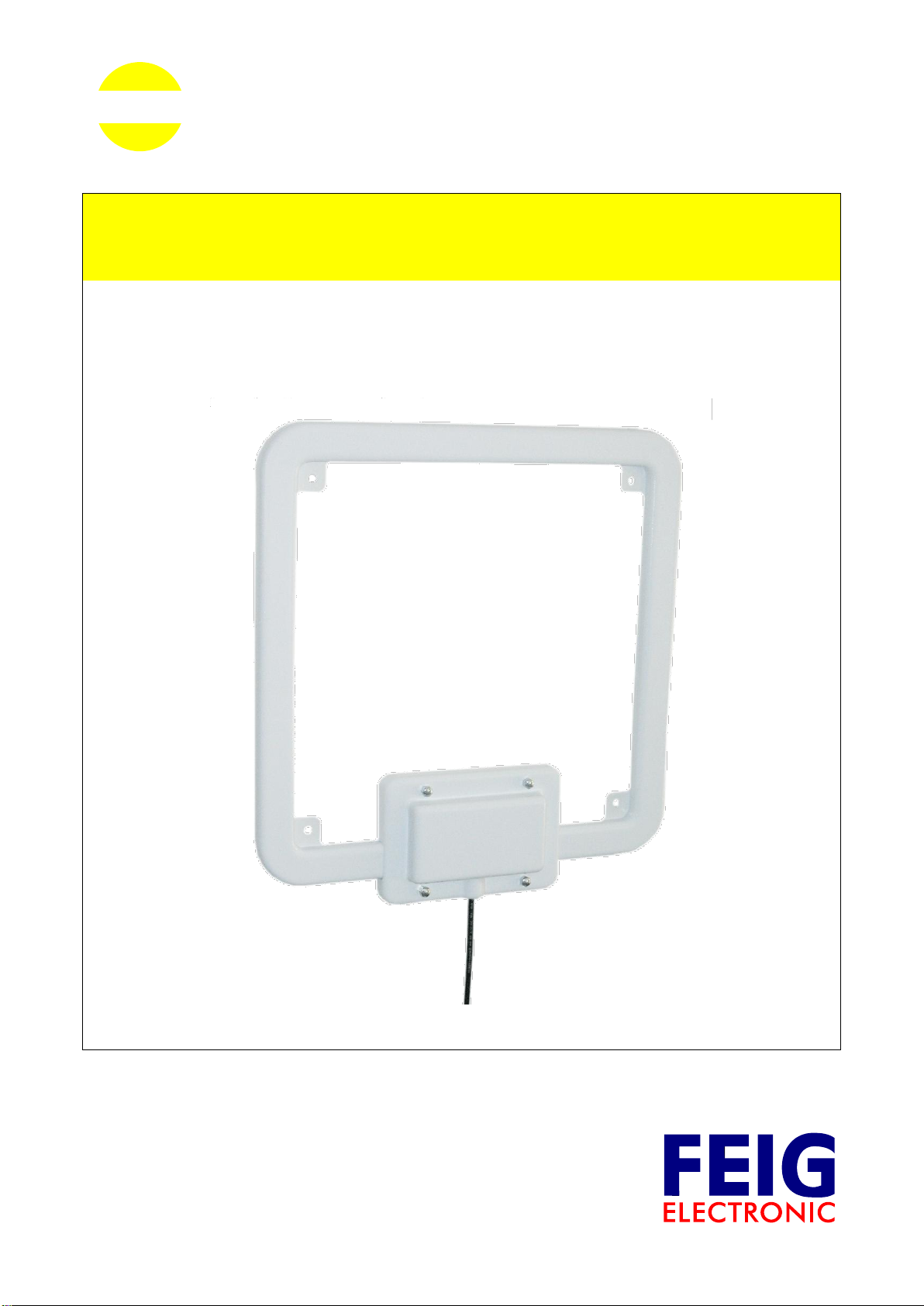
ID ISC.ANT310310-A
HF Antenna
(deutsch / english)
Page 7

OBID i-scan®
Montage
ID ISC.ANT310/310-A
FEIG ELECTRONIC GmbH
Seite 2 von 46
M90401-2de-ID-B.doc
D E U T S C H
Page 8
OBID i-scan®
Montage
ID ISC.ANT310/310-A
FEIG ELECTRONIC GmbH
Seite 3 von 46
M90401-2de-ID-B.doc
D E U T S C H
E N G L I S H
deutsche Version ab Seite 4
english version from page 26
Page 9

OBID i-scan®
Montage
ID ISC.ANT310/310-A
FEIG ELECTRONIC GmbH
Seite 4 von 46
M90401-2de-ID-B.doc
D E U T S C H
Hinweis
Copyright 2009-2011 by
FEIG ELECTRONIC GmbH
Lange Straße 4
D-35781 Weilburg
Tel.: +49 6471 3109-0
http://www.feig.de
Alle früheren Ausgaben verlieren mit dieser Ausgabe ihre Gültigkeit.
Die Angaben in diesem Dokument können ohne vorherige Ankündigung geändert werden.
Weitergabe sowie Vervielfältigung dieses Dokuments, Verwertung und Mitteilung ihres Inhalts sind nicht
gestattet, soweit nicht ausdrücklich zugestanden. Zuwiderhandlung verpflichtet zu Schadenersatz. Alle
Rechte für den Fall der Patenterteilung oder Gebrauchsmuster-Eintragung vorbehalten.
Die Zusammenstellung der Informationen in diesem Dokument erfolgt nach bestem Wissen und Gewissen.
FEIG ELECTRONIC GmbH übernimmt keine Gewährleistung für die Richtigkeit und Vollständigkeit der Angaben in diesem Dokument. Insbesondere kann FEIG ELECTRONIC GmbH nicht für Folgeschäden auf
Grund fehlerhafter oder unvollständiger Angaben haftbar gemacht werden. Da sich Fehler, trotz aller Bemühungen nie vollständig vermeiden lassen, sind wir für Hinweise jederzeit dankbar.
Die in diesem Dokument gemachten Installationsempfehlungen gehen von günstigsten Rahmenbedingungen aus. FEIG ELECTRONIC GmbH übernimmt weder Gewähr für die einwandfreie Funktion in systemfremden Umgebungen, noch für die Funktion eines Gesamtsystems, welches die in diesem Dokument beschriebenen Geräte enthält.
FEIG ELECTRONIC weist ausdrücklich darauf hin, dass die in diesem Dokument beschriebenen Geräte
nicht für den Einsatz mit oder in medizinischen Geräten oder für Geräte für lebenserhaltende Maßnahmen
konzipiert sind, bei denen ein Fehler eine Gefahr für menschliches Leben oder für die gesundheitliche Unversehrtheit zur Folge haben kann. Der Applikationsdesigner ist dafür verantwortlich geeignete Maßnahmen
zu ergreifen um Gefahren, Schäden oder Verletzungen zu vermeiden.
FEIG ELECTRONIC GmbH übernimmt keine Gewährleistung dafür, dass die in diesem Dokument enthaltenden Informationen frei von fremden Schutzrechten sind. FEIG ELECTRONIC GmbH erteilt mit diesem
Dokument keine Lizenzen auf eigene oder fremde Patente oder andere Schutzrechte.
OBID® und OBID i-scan® ist ein eingetragenes Warenzeichen der FEIG ELECTRONIC GmbH
Alle genannten Markennamen, Produktnamen oder Marken gehören ihren jeweiligen Inhabern.
Page 10

OBID i-scan®
Montage
ID ISC.ANT310/310-A
FEIG ELECTRONIC GmbH
Seite 5 von 46
M90401-2de-ID-B.doc
D E U T S C H
Inhalt
1 Sicherheits- und Warnhinweise - vor Inbetriebnahme unbedingt lesen 6
2 Leistungsmerkmale der Antenne ID ISC.ANT310/310-A 7
3 Montage und Anschluss 8
4 Inbetriebnahme 9
4.1 Projektierungshinweise .............................................................................................. 9
4.2 Konfiguration des RFID Reader gemäß der nationalen Funkvorschriften ............ 11
4.3 Der Einfluss der Sendeleistung des Readers auf die Lesereichweite................... 11
4.4 Der Einfluss von Metall auf die Reichweite ............................................................. 13
4.5 Der Einfluss der Noise Level auf die Reichweite der Antenne .............................. 14
4.6 Das Messen des Stehwellenverhältnisses VSWR .................................................. 15
4.7 Der Abgleich der Antenne ........................................................................................ 16
5 Der Verlauf der magnetischen Feldlinien der Antenne 20
6 Technische Daten 21
6.1 Zulassung .................................................................................................................. 22
6.1.1 Europa (CE) ........................................................................................................... 22
6.1.2 USA (FCC) und Kanada (IC) .................................................................................. 23
6.1.3 USA und Canada (UL) ........................................................................................... 24
7 Lieferumfang: 24
Page 11

OBID i-scan®
Montage
ID ISC.ANT310/310-A
FEIG ELECTRONIC GmbH
Seite 6 von 46
M90401-2de-ID-B.doc
D E U T S C H
1 Sicherheits- und Warnhinweise - vor Inbetriebnahme unbedingt lesen
Das Gerät darf nur für den vom Hersteller vorgesehenen Zweck verwendet werden.
Die Bedienungsanleitung ist zugriffsfähig aufzubewahren und jedem Benutzer auszuhändigen.
Unzulässige Veränderungen und die Verwendung von Ersatzteilen und Zusatzeinrichtungen,
die nicht vom Hersteller des Gerätes verkauft oder empfohlen werden, können Brände, elektrische Schläge und Verletzungen verursachen. Solche Maßnahmen führen daher zu einem
Ausschluss der Haftung und der Hersteller übernimmt keine Gewährleistung.
Für das Gerät gelten die Gewährleistungsbestimmungen des Herstellers in der zum Zeitpunkt
des Kaufs gültigen Fassung. Für eine ungeeignete, falsche manuelle oder automatische Einstellung von Parametern für ein Gerät bzw. ungeeignete Verwendung eines Gerätes wird keine
Haftung übernommen.
Reparaturen dürfen nur vom Hersteller durchgeführt werden.
Anschluss-, Inbetriebnahme-, Wartungs-, und sonstige Arbeiten am Gerät dürfen nur von Elekt-
rofachkräften mit einschlägiger Ausbildung erfolgen.
Alle Arbeiten am Gerät und dessen Aufstellung müssen in Übereinstimmung mit den nationa-
len elektrischen Bestimmungen und den örtlichen Vorschriften durchgeführt werden.
Beim Arbeiten am Gerät müssen die jeweils gültigen Sicherheitsvorschriften beachtet werden.
Beim Arbeiten am geöffneten Gerät ist zu beachten, dass Spannungen bis zu 1000V an den
Bauteilen anliegen können.
Besonderer Hinweis für Träger von Herzschrittmachern:
Obwohl dieses Gerät die zulässigen Grenzwerte für elektromagnetische Felder nicht überschreitet, sollten Sie einen Mindestabstand von 25 cm zwischen dem Gerät und Ihrem Herzschrittmacher einhalten und sich nicht für längere Zeit in unmittelbarer Nähe des Geräts bzw.
der Antenne aufhalten.
Verwenden Sie zur Reinigung der Antenne keine scharfen Chemikalien, Reiniger oder Lö-
sungsmittel. Wischen Sie die Antenne mit einem weichen, mit mildem Seifenwasser befeuchteten Tuch ab.
Page 12

OBID i-scan®
Montage
ID ISC.ANT310/310-A
FEIG ELECTRONIC GmbH
Seite 7 von 46
M90401-2de-ID-B.doc
D E U T S C H
2 Leistungsmerkmale der Antenne ID ISC.ANT310/310-A
Die Antenne ID ISC.ANT310/310-A ist eine Antenne mit manuell einbestellbarer Abgleichelektronik. Sie wird bereits ab Werk für die meisten Anwendungen abgeglichen. Sie kann aber
auch mit Hilfe von Steckbrücken (Jumpern), auf verschiedene Umgebungsbedingen optimal
eingestellt werden.
In Kombination mit verschieden Lesern der Firma FEIG Electronic GmbH kann die Antenne in
vielen Long– und Mid–Range Applikationen bei optimalen Leseergebnissen Anwendungen finden.
Bei einer Sendeleistung von 8 W und einem Transponder in ISO Kartengröße, sind typischerweise
Lesereichweiten von 60-70 cm möglich.
Auch ist ein Betrieb an anderen Readern mit einer Sendefrequenz von 13,56 MHz und der
Ausgangsimpedanz von 50 möglich.
Durch ihre robuste Bauweise in Verbindung mit der Schutzklasse IP65 ist sie für nahezu alle
Anwendungen einsetzbar.
Typische Anwendungen sind Bibliotheken, Dokumentenverfolgung, Videotheken,
Labelprogrammierung, Logistik an Förderstrecken oder Sortieranlagen, Zutrittskontrolle,
Personenerkennung und Erfassung von Daten im Büro oder in der Industrie.
Page 13
OBID i-scan®
Montage
ID ISC.ANT310/310-A
FEIG ELECTRONIC GmbH
Seite 8 von 46
M90401-2de-ID-B.doc
D E U T S C H
Antennenöffnung
(Deckel)
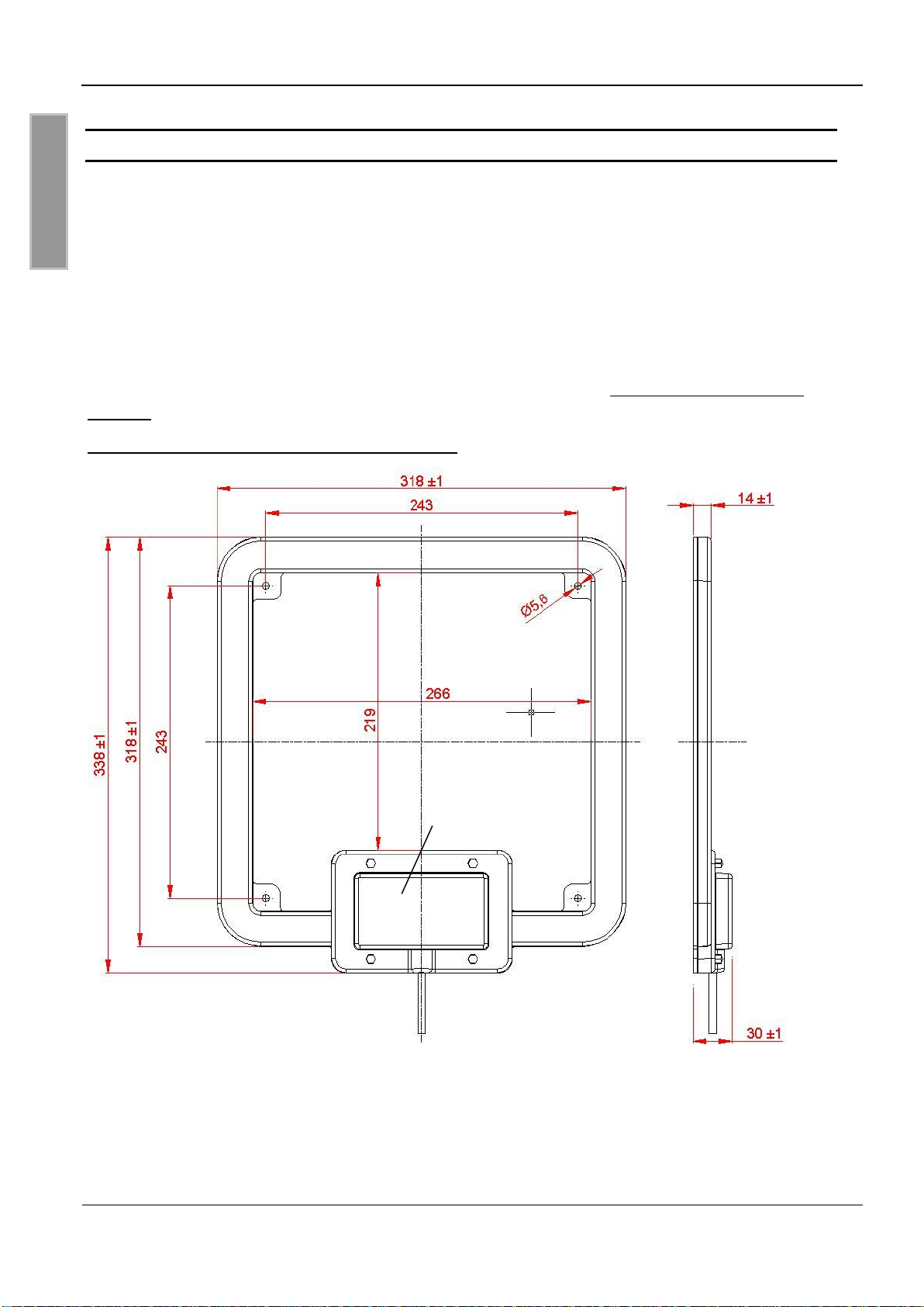
3 Montage und Anschluss
Die Antenne ist für die Montage an Halterungen aus nicht leitende Materialien (z.B. Kunststoff oder
Holz) sowohl für den Innen- wie auch den Außenbereich konzipiert. Zur Montage befinden sich im
Innenbereich der Antenne 4 Bohrungen (d=5,6 mm) im Abstand von 243 mm. Zur Montage empfehlen wir eine 5 mm Holzschraube (DIN 96) oder eine Maschinenschraube (DIN 7985) mit einem
Kopfdurchmesser von mindestens 10 mm bis maximal 12 mm. Das maximale Anzugsmoment für
freidrehende Schrauben beträgt 2,0 Nm.
Die Antenne muss einen Mindestabstand von 5 cm von eventuellen Metallteilen haben!
Bis zu 40 cm Abstand zu Metallteilen muss mit Einbußen in der Lesereichweite gerechnet werden.
Dies kann durch nachgleichen der Antenne verringert werden. Siehe Seite 16 Der Abgleich der
Antenne.
Bild 1: Montagezeichnung ID ISC.ANT310/310-A
Alle Maße in mm
Zum Abgleichen der Antenne muss der Deckel über der Antennenöffnung entfernt werden. Das
Anzugsmoment der Deckelschrauben beträgt minimal 0,7 Nm bis maximal 0,9 Nm.
Page 14
OBID i-scan®
Montage
ID ISC.ANT310/310-A
FEIG ELECTRONIC GmbH
Seite 9 von 46
M90401-2de-ID-B.doc
D E U T S C H
Reader
ID ISC.ANT310/310-A
Reader
ID ISC.ANT.PS-B
ID ISC.ANT310/310-A
Erfassungsbereich
4 Inbetriebnahme
4.1 Projektierungshinweise
Die Antenne ID ISC.ANT310/310-A wird mit Hilfe des Anschlusskabels und dem SMA- Stecker
direkt an den Reader angeschlossen.
Bild 2: Schaltskizze Reader und Antenne
Die Antenne ID ISC.ANT310/310-A ermöglicht eine Erfassung der Transponder die sich im Erfassungsbereich der Antenne befinden. Die bevorzugte Ausrichtung der Transponder ist in paralleler
Ausrichtung zur Antennenfläche. Die größte Lesereichweite wird über der Mitte der Antennenfläche erreicht. Exakt über den Antennenleiter sinkt die Reichweite auf Null.
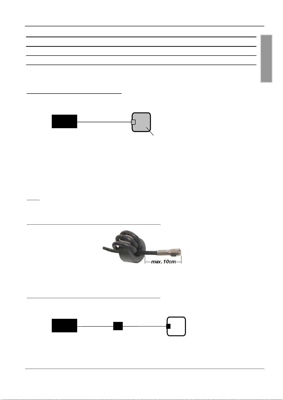
Um mögliche Störungen, im Frequenzbereich 20-100MHz zu unterdrücken, werden dem Readern
ID ISC.LR2000 und ID ISC.MR200 zwei bzw. ein Ringkern(e) beigelegt. Einer dieser Ringkerne
muss in das Antennenanschlusskabel eingebaut werden. Dafür ist das koaxiale Kabel vier mal,
eng anliegend durch den EMV - Ringkern zu schleifen. Der Abstand zwischen Readeranschluss
und Ringkern sollte dabei maximal 10 cm betragen.
Bild 3: Montage des Ringkerns auf der Antennenzuleitung
Um Störungen in industriellen Umgebungen, im Frequenzbereich 1-10MHz, zu unterdrücken empfehlen wir zusätzlich das Gerät ID ISC.ANT.PS-B, in der Betriebsart Transformer, zwischen Reader und Antenne zu schalten.
Bild 4: Schaltskizze Reader mit Transformer und Antenne
Hinweis: Das maximale Anzugsdrehmoment der SMA-Buchse beträgt 0,45 Nm.
Page 15

OBID i-scan®
Montage
ID ISC.ANT310/310-A
FEIG ELECTRONIC GmbH
Seite 10 von 46
M90401-2de-ID-B.doc
D E U T S C H
2
Die folgenden Empfehlungen sollten zusätzlich beachtet werden:
Bis zu einem Abstand von 50 cm sollte das Antennenkabel immer senkrecht von der Antenne
weg geführt und komplett fest verlegt werden.
Um optimale Lesereichweiten zu erzielen sollte das Antennenanschlusskabel nicht verkürzt
oder verlängert werden. Ist eine Verlängerung zwingend erforderlich, so kann dies mit dem
50 Kabel ID ISC.ANT.EC in der Länge
(halbe Wellenlänge bei 13,56 MHz,
RG58= 7,20 m) durchgeführt werden. Dabei ist mit geringen Einbußen der Lesereichweite zu
rechnen (ca.2-3 cm / Verlängerung).
Das Antennenkabel muss einen Mindestabstand von 30 cm zu parallel geführten , stromfüh-
renden Leitungen haben.
Nach der Montage kann die korrekte Funktion der Antenne mit Hilfe des Readers und eines
Transponders geprüft werden. Bei einer am Reader eingestellten Sendeleistung von 4 W und einer
Größe der Transponderspule von 75 mm x 46 mm (ISO-Kartengröße) sollte die Lesereichweite in
der Mitte der Antenne bei ca. 50 cm – 60 cm liegen.
Andernfalls sollten folgende Punkte überprüft werden:
Wurde die Antenne in der Nähe von Metall installiert
Wie hoch ist der Unterschied zwischen Umax-Umin der Noise Level. Die Differenz der Noise
Level im Diagramm (ISO Start, Test & Measurement) sollte kleiner gleich 20 mV sein.
Stimmt die Anpassung der Antenne an die Impedanz von 50 nicht
Kann mit Hilfe eines SWR – Meters überprüft werden. Siehe Seite 15 Das Messen des
Stehwellenverhältnisses VSWR
Meldet der Reader eine „RF-Warning“, siehe Reader Kommando „[0x6E] Reader
Diagnostic“ im Handbuch des Readers
Der Abstand von Transponder zu Transponder (ISO-Kartengröße) sollte mindestens 8 cm be-
tragen. Wird der Abstand von Transponder zu Transponder verringert ist mit Einbusen in der
Lesereichweite zu rechnen. Dies gilt besonders bei Abständen unter 5 cm.
Werden mehrere Antennen gleichzeitig im Abstand von kleiner 8 m (ID ISC.LR2000) betrieben,
so müssen die Reader synchronisiert werden. Andernfalls ist mit Einbusen in der
Lesereichweite zu rechnen.
Siehe: Application Note: Synchronizing RFID Long Range Readers using the Reader
Synchronization Interface (N11200-3e-ID-B.pdf).
Page 16

OBID i-scan®
Montage
ID ISC.ANT310/310-A
FEIG ELECTRONIC GmbH
Seite 11 von 46
M90401-2de-ID-B.doc
D E U T S C H
4.2 Konfiguration des RFID Reader gemäß der nationalen Funkvorschriften
Die Konfiguration der RFID Reader und die maximale Sendeleistung der Antennen werden im wesentlichen durch die länderspezifischen Funkvorschriften beeinflusst. Für den gesamten EU gelten
einheitliche Grenzwerte nach der R&TTE Richtlinie und EN 300 330. In Nord Amerika wird dies
durch die Vorschriften FCC Part 15 und RSS210 (Kanada) geregelt.
Die Antenne ID ISC.ANT310/310 mit dem Lesern ID ISC.LR2000, ID ISC.LR2500, ID ISC.MR200
und ID ISC.MR101 entspricht, bei bestimmungsgemäßer Verwendung den grundlegenden Anforderungen des Artikels 3 und den übrigen einschlägigen Bestimmungen der R&TTE Richtlinie
1999/5/EG vom März 99. Daher ist der Betrieb in den 29 EU-Staaten und den EFTA Staaten (EUStaaten und Schweiz, Norwegen und Island) mit einer maximalen Feldstärke von 42 dBµA/m in 10
m Entfernung möglich (Sendeleistung des Lesers = 4W).
Eine Funkzulassung (bei einer maximalen Feldstärke von 84 dBµV/m in 30 m Entfernung) für die
Antenne ID ISC.ANT310/310 mit dem Leser ID ISC.LRM2500 und ID ISC.LR2000 nach FCC Part
15 für die USA und RSS 210 für Kanada wurde erteilt.
Weiterhin ist eine Funkzulassung nach der Norm EN 300 330 in allen 46 CEPT Staaten möglich.
Die CEPT Staaten sind:
Albania (ALB), Andorra (AND), Austria (AUT), Azerbaijan (AZE), Belarus (BLR), Belgium (BEL),
Bulgaria (BUL), Bosnia and Herzegovina (BIH), Croatia (HRV), Cyprus (CYP), Czech Republic
(CZE), Denmark (DNK), Estonia (EST), Finland (FIN), France (F), Germany (D), Greece (GRC),
Hungary (HNG), Iceland (ISL), Ireland (IRL), Italy (I), Latvia (LVA), Liechtenstein (LIE), Lithuania
(LTU), Luxembourg (LUX), Malta (MLT), Former Yugoslav Republic of Macedonia (MKD), Moldova
(MDA), Monaco (MCO), Netherlands (HOL), Norway (NOR), Poland (POL), Portugal (POR), Romania (ROU), Russian Federation (RUS), San Marino (SMR), Slovak Republic (SVK), Slovenia
(SVN), Spain (E), Sweden (S), Switzerland (SUI), Turkey (TUR), Ukraine (UKR), United Kingdom
(G), Vatican City (CVA) and Yugoslavia.
Es gelten folgende Einschränkungen (Stand: Oktober 2009):
1. Außerhalb der EFTA Staaten muss in jedem Fall eine Funkzulassung beantragt werden. Die
vorhandenen Messprotokolle nach EN 300 330 sind in der Regel ausreichend.
Bei der Inbetriebnahme der Antennen ist vom Systemintegrator darauf zu achten, dass die
vorgeschriebenen Montagehinweise beachtet, die notwendigen Einstellungen im Reader
durchgeführt und zulässigen Grenzwerte der nationalen Funkvorschriften nicht überschritten
werden.
Page 17
OBID i-scan®
Montage
ID ISC.ANT310/310-A
FEIG ELECTRONIC GmbH
Seite 12 von 46
M90401-2de-ID-B.doc
D E U T S C H
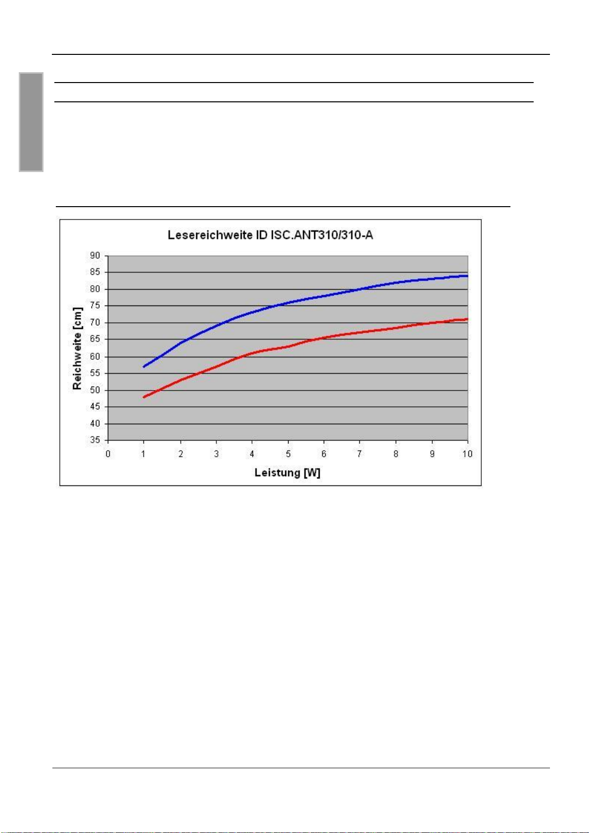
4.3 Der Einfluss der Sendeleistung des Readers auf die Lesereichweite
Die Reichweite einer Antenne ist abhängig von der Antenne selbst, dem Reader, den Eigenschaften der Transponder und der eingestellten Sendeleistung des Readers. Da der Transponder seine
Energie aus dem von der Antenne erzeugten magnetischen Feld bezieht und die Feldstärke mit
dem Abstand zwischen Reader und Antenne stark abnimmt, hat die abgestrahlte Sendeleistung
bei gegebener Antenne eine starken Einfluss auf die Reichweite.
Bild 5: Die Lesereichweite der Antenne ID ISC.ANT310/310 in Abhängigkeit der Sendeleistung
Lesereichweite zweier typischer Transponder 46 x 75 mm2, über der Antennen Mitte, parallele
Ausrichtung des Labels zur Antenne.
Eine Sendeleistung über 8 W kann in Abhängigkeit der Umgebungstemperatur zur übermäßigen
Erwärmung der Antenne und somit zur Zerstörung der Antenne führen.
Page 18

OBID i-scan®
Montage
ID ISC.ANT310/310-A
FEIG ELECTRONIC GmbH
Seite 13 von 46
M90401-2de-ID-B.doc
D E U T S C H
4.4 Der Einfluss von Metall auf die Reichweite
Metall und andere leitende Stoffe kann ein magnetisches Feld nicht durchdringen. Der Feldlinienverlauf und die Induktivität der Antenne wird verändert und hat somit einen großen Einfluss auf die
Reichweite. Weiterhin wird das Feld durch die Gegeninduktivität bzw. die Wirbelströme im Metall
geschwächt.
Die Änderung der Induktivität kann mit Hilfe der Abgleichelektronik ausgeglichen werden. Bild 6
zeigt den Einfluss einer Metallplatte auf die Antenne mit und ohne Nachgleich.
Bild 6: Lesereichweite* in Abhängigkeit zum Abstand zu Metall
Mit Nachgleichen der Antenne, Ohne Nachgleichen
Transponder 46 x 75 mm2 , über der Antennen Mitte, parallele Ausrichtung des Labels zur
Antenne. Sendeleistung 4 W.
Ist Metall in der Nähe der Antenne nicht zu vermeiden sollte folgendes beachtet werden:
Mindestabstand Metall zur Antenne 5 cm. Bis zu 30 cm ist mit starken Einbusen der Lese-
reichweite zu rechnen. Ab 50 cm Abstand zum Metall ist nahezu kein Einfluss messbar.
Die Metallteile dürfen keine geschlossenen Schleifen oder Stromkreise bilden. Diese sind ge-
gebenenfalls an einer Stelle elektrisch zu trennen.
Die Metallteile in unmittelbarer Nähe der Antenne sind mit einer guten HF-Verbindung stern-
förmig zu Erden.
Page 19
OBID i-scan®
Montage
ID ISC.ANT310/310-A
FEIG ELECTRONIC GmbH
Seite 14 von 46
M90401-2de-ID-B.doc
D E U T S C H
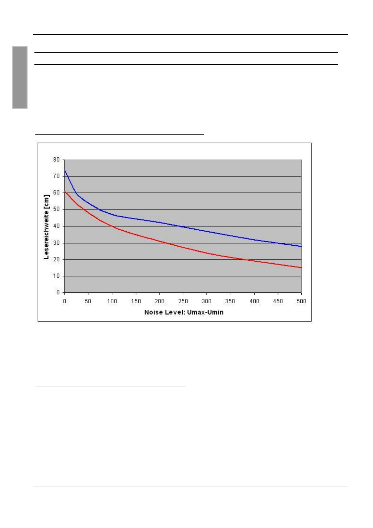
4.5 Der Einfluss der Noise Level auf die Reichweite der Antenne
Damit der Transponder vom Empfänger auch bei kleinen Signalpegeln zuverlässig gelesen werden
kann, müssen Störungen weitgehend vermieden werden. Die Amplitude der Störpegel lässt sich
am Reader ID ISC.LR2000 an Hand der Noise Level (Rausch Pegel) abfragen. Dabei sind nicht
die absoluten Messwerte sondern die Differenz zwischen Umax und Umin ausschlaggebend.
Im folgenden Bild wurde dies bei 4 W Sendeleistung simuliert und grafisch dargestellt.
Bild 7: Lesereichweite* in Abhängigkeit der Noise Level
Lesereichweite zweier typischer Transponder 46 x 75 mm2, über der Antennen Mitte, parallele
Ausrichtung des Labels zur Antenne.
Die Differenz der Noise Level (Umax-Umin) sollte kleiner gleich 20 mV sein.
Ursache für zu hohe Noise Level können sein:
Schlechte (HF-)Verbindungen zwischen Reader und Antenne.
Falsche Kabelführung zwischen Antenne und Reader
Eine schlecht abgestimmte Antenne
Störsignale von anderen elektronischen Geräten oder Sendern.
Störsignale auf der Energieversorgungsleitung des Readers
Störsignale von anderen Kabel in der Nähe der Kabel zum und vom Reader
Metall in der Nähe der Antenne
Page 20
OBID i-scan®
Montage
ID ISC.ANT310/310-A
FEIG ELECTRONIC GmbH
Seite 15 von 46
M90401-2de-ID-B.doc
D E U T S C H
Antenne
ID ISC.ANT310/310
SWR / Power Meter
Reader
ID ISC.LR2000
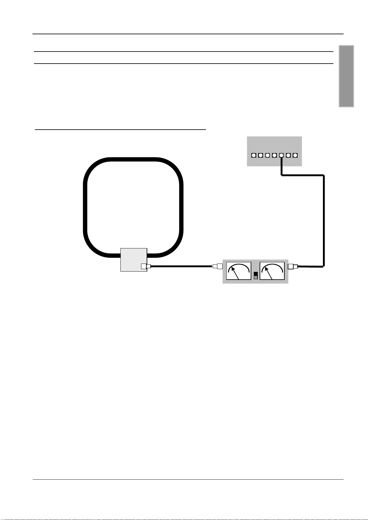
4.6 Das Messen des Stehwellenverhältnisses VSWR
Wurde eine Antenne abgeglichen oder haben sich die Umgebungsbedingungen geändert, stellt
sich die Frage: Wie gut ist die Anpassung zwischen Reader und Antenne? Ein nützliches Hilfsmit-
tel zu Beurteilung der Anpassung der Antenne an die Impedanz von 50 ist das VSWR Meter.
Dieses Gerät misst das Verhältnis zwischen zugeführter und reflektierter Energie. Dabei gilt ein
VSWR bis zu 1.3 :1 als guter Wert. In VSWR-Meter sind sehr oft auch Watt-Meter integriert.
Bild 8:Einbau eines VSWR-Meters in das Antennenkabel
Das Kabel zwischen Reader und SWR Meter sollte entweder sehr kurz (< 20 cm) oder 7,20 m (RG
58=Lamba/2) lang sein.
Liegt das VSWR über 1,3 :1, kann die Antenne mit Hilfe der Jumperleisten J1, J2 und J3
nachgeglichen werden.
Weiterhin kann mit dem Gerät jederzeit die Abstimmung der Antennen kontrolliert werden. Kommt
es zu einer Verstimmung der Antenne durch Änderungen der Umgebungsbedingungen, lässt sich
dies somit feststellen.
Zusätzlich zu den vom SWR angezeigten Verlusten durch die Fehlanpassung zwischen Kabel und
Antenne kommt, dass der Reader in Abhängigkeit von der Antennenimpedanz verschiedene
Ausgangsströme treibt und somit verschiedene Leistungen ausgibt. Das heißt bei 50 fließt ein
Strom von ca. 0.3 A. Bei einem offenen Ausgang fließt kein Strom, im Kurzschlussfall wird der
Strom auf ca. 1,0 A begrenzt.
Die Anpassung der Antenne hat auch einen geringen Einfluss auf die Höhe der Noise Level /
Rausch Pegel des Systems und somit ein weiteren Einfluss auf die Lesereichweite.
Page 21

OBID i-scan®
Montage
ID ISC.ANT310/310-A
FEIG ELECTRONIC GmbH
Seite 16 von 46
M90401-2de-ID-B.doc
D E U T S C H
Bild 9: Die Impedanz und Phase der Antenne in Abhängigkeit von der Frequenz
(gemessen am SMA Stecker)
4.7 Der Abgleich der Antenne
Die Antenne wurde im Werk an einer Holzplatte auf die Impedanz von 50 abgestimmt. Wird sie
in einem definierten Abstand von Metall oder anderen leitenden Stoffen montiert, ist keinerlei abgleichen oder nachgleichen der Antenne notwendig.
Nach der Montage in anderen Umgebungsbedingungen kann die Antenne mit Hilfe von Jumpern
neu abgestimmt werden. Dafür sollte entweder ein SWR – Meter oder ein Messgerät zur Bestimmung der Impedanz bei 13,56 MHz (Antennen/Impedanz Analyzer) vorhanden sein.
Vor dem Abgleichen der Antenne muss diese und das Antennenkabel fest montiert werden. Ein
eventuell notwendiger Power Splitter oder Transformer sollte erst nach dem Abgleich der Antennen eingebaut werden.
Page 22
OBID i-scan®
Montage
ID ISC.ANT310/310-A
FEIG ELECTRONIC GmbH
Seite 17 von 46
M90401-2de-ID-B.doc
D E U T S C H
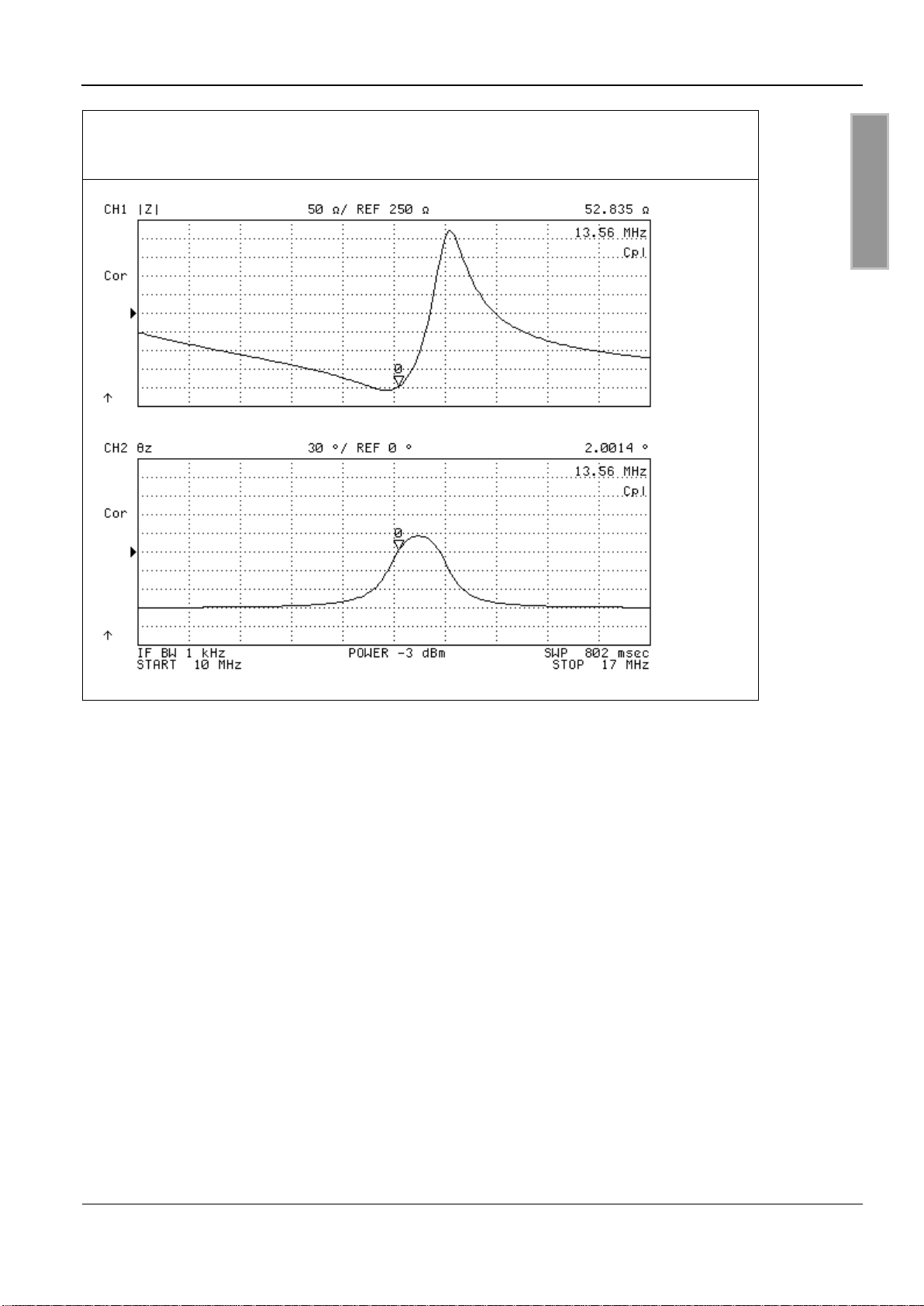
Bild 10: Die Impedanz und Phase der Antenne in Abhängigkeit von der Frequenz
(direkt an der Antenne ohne Kabel)
Bild 10 beschreibt den Verlauf der Impedanz und Phase, der Antenne ID ISC.ANT310/310-A über
der Frequenz. Wurden die Antennen richtig abgeglichen liegt das Minimum (Reihenresonanz) der
Impedanzkurve bei 13.56 MHz, 50 und einem Phasenwinkel von 0°. Wird Metall in die Nähe der
Antenne gebracht, so verschiebt sich die Impedanzkurve nach rechts und leicht nach unten. D.h.
kommt die Antenne näher an Metall wird die Impedanz zuerst kleiner und dann immer größer. Dabei passiert die Antenne wieder die 50 Wert. Dieser Arbeitspunkt führt allerdings systembedingt
nicht zu optimalen Lesereichweiten. Der optimale Arbeitspunkt liegt immer auf der Serienresonanz
welcher hier dem Minimum in der Impedanzkurve entspricht.
Page 23
OBID i-scan®
Montage
ID ISC.ANT310/310-A
FEIG ELECTRONIC GmbH
Seite 18 von 46
M90401-2de-ID-B.doc
D E U T S C H
Abstand zur
Metallplatte
Pin Nummer für Jumper gesteckt
J1
J2
J3
2,5 cm
5-6,7-8,9-10,11-12
5-6,7-8,9-10,11-12
3-4,9-10,13-14,15-16,17-18
5 cm
3-4,5-6,9-10,11-12
3-4,5-6,9-10,11-12
9-10,15-16, 17-18
7,5 cm
5-6,9-10,11-12
5-6,9-10,11-12
3-4,7-8,9-10,11-12,13-14,17-18
10 cm
3-4,7-8,11-12
3-4,7-8,11-12
1-2,3-4,7-8,11-12,13-14,17-18
15 cm
3-4,7-8,11-12
3-4,7-8,11-12
11-12,13-14,17-18
20 cm
3-4,7-8,11-12
3-4,7-8,11-12
3-4,7-8,9-10,13-14,17-18
25 cm
3-4,7-8,11-12
3-4,7-8,11-12
7-8,9-10,13-14,17-18
30 cm
3-4,7-8,11-12
3-4,7-8,11-12
1-2,3-4,5-6,9-10,13-14,17-18
35 cm
3-4,7-8,11-12
3-4,7-8,11-12
1-2,3-4,5-6,9-10,13-14,17-18
40 cm
3-4,7-8,11-12
3-4,7-8,11-12
1-2,3-4,5-6,9-10,13-14,17-18
Ohne Metallplatte
3-4,7-8,11-12
3-4,7-8,11-12
1-2,3-4,5-6,9-10,13-14,17-18
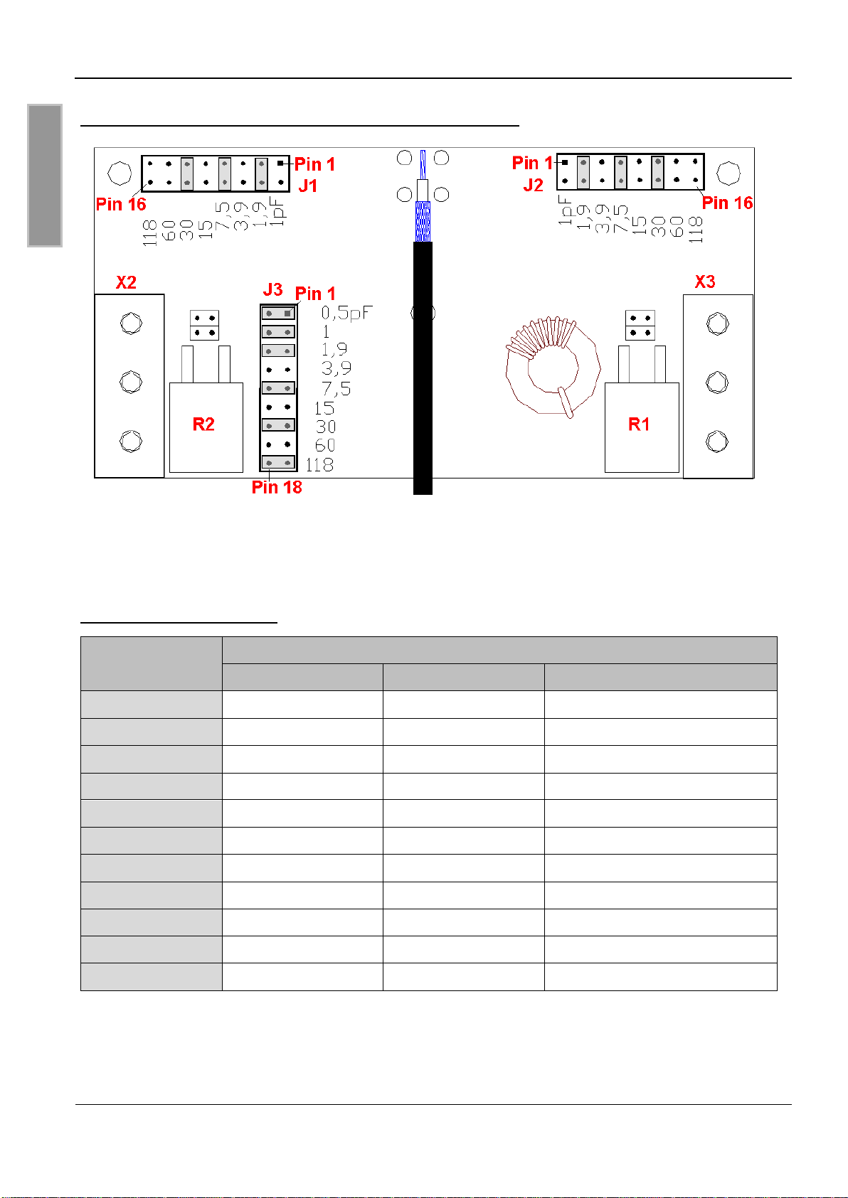
Bild 11: Draufsicht : Leiterplatte mit Standard Jumperpositionen
Um das Nachgleichen bzw. Abgleichen der Antenne zu erleichtern, wurde folgende Tabelle erstellt,
die als Richtwert oder Startwert für den Abgleichvorgang benutzt werden kann. Anschließend ist
die Impedanz der Antenne oder das VSWR zu kontrollieren und die Jumperpositionen auf den optimalen Messwert anzupassen.
Tabelle 1: Jumperpositionen
Die Einstellung ohne Metallplatte ist die Standardeinstellung !
Page 24

OBID i-scan®
Montage
ID ISC.ANT310/310-A
FEIG ELECTRONIC GmbH
Seite 19 von 46
M90401-2de-ID-B.doc
D E U T S C H
Ziel des Abgleichvorgangs ist die Impedanz der Antenne wieder möglichst nahe auf 50
abzugleichen. Dabei sind folgende Toleranzen einzuhalten:
R = 50 +/- 3 und X = 0 +/- 5 bzw. Z = 50 +/- 3 und Phasenwinkel Phi = 0° +/- 5°
oder VSWR <= 1.3
Um die Antenne wieder auf 50 und einem Phasenwinkel von 0°nachzupassen, kann mit Hilfe der
Jumperleisten J1,J2 und J3 ein nachgleich erfolgen. Siehe auch: Das Messen des Stehwellenver-
hältnisses VSWR.
Dabei ist folgendermaßen vorzugehen:
1. Einstellen der Jumperleisten J1,J2 und J3 nach Tabelle 1
2. Einstellen der Kapazitäten J3 auf den besten Wert Nahe 50 und Phasenwinkel 0° (kleinster
Wert VSWR)
3. Einstellen der Kapazitäten J1,J2 auf den besten Wert Nahe 50 und Phasenwinkel 0°° (kleinster Wert VSWR)
4. Wiederholen der Schritte 2. + 3. bis 50 ± 1 und Phasenwinkel 0°± 3° erreicht werden. °
(kleinster Wert VSWR <=1:1.3)
Das Einstellen der Kapazitäten J1,J2,J3 auf den besten Wert Nahe 50 und Phasenwinkel 0°
erfolgt durch stecken oder entfernen der Jumper. Dabei ist der Messwert am Messgerät vor und
nach der Änderung zu vergleichen.
Es sind zuerst die kleinen Kapazitäten zu ändern. Bringt dies eine Verbesserung oder ist der Jumper schon gesteckt wird mit dem nächst größeren Wert fortgefahren.
Bringt das Schließen der Brücke Pin1-2 eine Verbesserung, so wäre der nächste Schritt, dass
Schließen von Pin 3-4 und öffnen von Pin 1-2, da der Kondensator an Pin 3-4 ungefähr den doppelten Wert des Kondensator an Pin 1-2 hat..
Die Jumper an Leiste J1 und J2 sollten immer möglichst gleich gesteckt sein. Große Kapazitäten
an Leiste J1 und kleine Kapazitäten an Leiste J2 führen zu einer Unsymmetrie in der Antenne.
Dies kann zu Leistungseinbusen und Beschädigung der Bauteile in der Antenne führen
Achtung: Am Antennenleiter oder an verschiedenen Bauteilen der Abgleichplatinen können
Spannungen bis zu 1000V auftreten. Vor dem Beginn der Arbeiten muss die Antenne von
dem Reader getrennt werden. Beim Abgleichen ist darauf zu achten, dass keine Bauteile
innerhalb des Gehäuse berührt werden.
Page 25
OBID i-scan®
Montage
ID ISC.ANT310/310-A
FEIG ELECTRONIC GmbH
Seite 20 von 46
M90401-2de-ID-B.doc
D E U T S C H
Label
Transponder
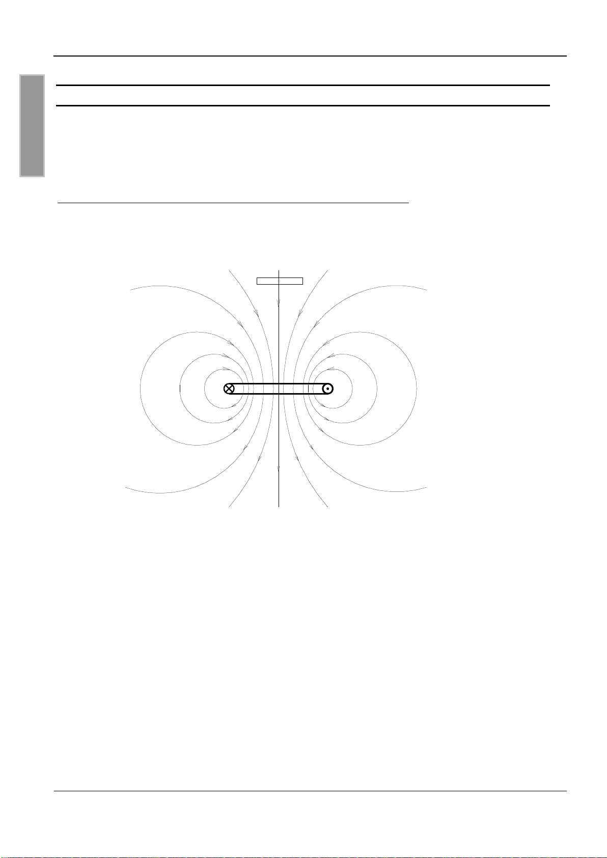
5 Der Verlauf der magnetischen Feldlinien der Antenne
Bild 12 zeigt die Feldausrichtung einer einfachen Single Loop Antenne. Sie ist die einfachste und
am meisten verwendete Antennenform im Bereich OBID i-scan. Die Antennengröße hängt dabei
stark von den Anforderungen an die Lesereichweite und der Einsatzumgebung und den nationalen
Grenzwerten ab.
Bild 12:Verlauf der magnetischen Feldlinien einer Single Loop Antenne
Die Reichweite einer Antenne ist abhängig von Position und Ausrichtung der Transponder. Eine
Single Loop Antenne hat die größte Reichweite in der Mitte der Antenne und einer Ausrichtung der
Transponder parallel zur Antennenfläche.
Der Transponder wird nur mit Energie versorgt, wenn ausreichend Feldlinien durch ihn fließen.
Daher ist das Aktivieren der Transponder in senkrecht Ausrichtung zur Antennenfläche, innerhalb
der Antennenfläche, nicht möglich.
Page 26

OBID i-scan®
Montage
ID ISC.ANT310/310-A
FEIG ELECTRONIC GmbH
Seite 21 von 46
M90401-2de-ID-B.doc
D E U T S C H
Mechanische Daten
Gehäuse
Kunststoff ABS-ASA
Abmessungen ( B x H x T )
318 mm x 338 mm x 30 mm 1 mm
Gewicht
ca. 0,7 kg
Schutzart
IP 65
Farbe
weiß
Elektrische Daten
Maximale Sendeleistung
8 W
Zulässige Sendeleistung
– EU-Raum (REC 70-03 An. 9F1)**
– EU-Raum (EN 300 330)
– USA (FCC Part 15)
8,0 W
4,0 W
4,0 W
Betriebsfrequenz
13.56 MHz
Reichweite
– 1 W (ID ISC.MR101)
– 1.8 W (ID ISC.MR200)
– 4 W
– 8 W
Typisch 43 cm *
Typisch 50 cm *
Typisch 60 cm *
Typisch 70 cm *
Antennenanschluss
1 x SMA Stecker (50 )
Antennenanschlusskabel
RG58, 50 , ca. 3,56 m lang
Umgebungsbedingungen
Temperaturbereich
– Betrieb
– Lagerung
–25°C bis +55°C
–25°C bis +60°C
Vibration
EN60068-2-6
10 Hz bis 150 Hz : 0,15 mm / 20m/s2 (~ 2 g)
6 Technische Daten
Page 27

OBID i-scan®
Montage
ID ISC.ANT310/310-A
FEIG ELECTRONIC GmbH
Seite 22 von 46
M90401-2de-ID-B.doc
D E U T S C H
Schock
EN60068-2-27
Beschleunigung : 300m/s2 (~ 30 g)
Angewendete Normen
EMV
EN 300 683
Sicherheit
– Niederspannungsrichtlinie
– Human Exposure
UL 60950-1
EN 50364
*Transponder Spule 46 x 75 mm2, über der Antennen Mitte, Empfindlichkeit / Minimale Feldstärke
H
=60mA/m rms, parallele Ausrichtung der Transponder zur Antenne. Sendeleistung 4 /8 W.
min
**In Verbindung mit dem Leser ID ISC.LR2000 gemäß der Funkvorschriften EN 300 330 und ERC
Recommendation 70-03 Annex 9 Vol. F1
6.1 Zulassung
6.1.1 Europa (CE)
Die Funkanlage entspricht, bei bestimmungsgemäßer Verwendung den grundlegenden Anforderungen des Artikels 3 und den übrigen einschlägigen Bestimmungen der R&TTE Richtlinie
1999/5/EG vom März 99.
Equipment Classification according ETSI EN 300 330 und ETSI EN 301 489: Class 2
Page 28

OBID i-scan®
Montage
ID ISC.ANT310/310-A
FEIG ELECTRONIC GmbH
Seite 23 von 46
M90401-2de-ID-B.doc
D E U T S C H
Product name:
ID ISC.ANT310/310
Antenna name:
ID ISC.ANT310/310-A
Reader name:
ID ISC.LRM2500
FCC ID:
IC:
PJMLRM2500
6633A-LRM2500
Notice for USA and
Canada
This device complies with Part 15 of the FCC Rules and with
RSS-210 of Industry Canada.
Operation is subject to the following two conditions.
(1) this device may not cause harmful interference, and
(2) this device must accept any interference received,
including interference that may cause undesired operation.
Unauthorized modifications may void the authority granted under
Federal communications Commission Rules permitting the operation
of this device.
This equipment has been tested and found to comply with the limits for
a Class A digital device, pursuant to Part 15 of the FCC Rules. These
limits are designed to provide reasonable protection against harmful
interference when the equipment is operated in a commercial
environment. This equipment generates, uses, and can radiate radio
frequency energy and, if not installed and used in accordance with the
instruction manual, may cause harmful interference to radio
communications. Operation of this equipment in a residential area is
likely to cause harmful interference in which case the user will be
required to correct the interference at his own expense.
Le présent appareil est conforme aux CNR d'Industrie Canada applicables aux appareils radio exempts de licence. L'exploitation est autorisée aux deux conditions suivantes :
(1) l'appareil ne doit pas produire de brouillage, et
(2) l'utilisateur de l'appareil doit accepter tout brouillage radioélectrique
subi, même si le brouillage est susceptible d'en compromettre le fonctionnement.
6.1.2 USA (FCC) und Kanada (IC)
Weitere Informationen und technischen Daten des Readers ID ISC.LRM2500 finden Sie in
der Montageanleitung, die dem Reader beiliegt.
Page 29

OBID i-scan®
Montage
ID ISC.ANT310/310-A
FEIG ELECTRONIC GmbH
Seite 24 von 46
M90401-2de-ID-B.doc
D E U T S C H
6.1.3 USA und Canada (UL)
Das folgende Bild zeigt die Position der Aufkleber:
7 Lieferumfang:
HF Antenne ID ISC.ANT310310-A
8 Stück Jumper
Montageanleitung
Page 30

Page 31

OBID i-scan®
Installation
ID ISC.ANT310/310-A
FEIG ELECTRONIC GmbH
Page 26 of 46
M90401-2de-ID-B.doc
E N G L I S H
Note
Copyright 2009-2011 by
FEIG ELECTRONIC GmbH
Lange Strasse 4
D-35781 Weilburg
Tel.: +49 6471 3109-0
http://www.feig.de
With the edition of this document, all previous editions become void. Indications made in this manual may be
changed without previous notice.
Copying of this document, and giving it to others and the use or communication of the contents thereof are
forbidden without express authority. Offenders are liable to the payment of damages. All rights are reserved
in the event of the grant of a patent or the registration of a utility model or design.
Composition of the information in this document has been done to the best of our knowledge. FEIG
ELECTRONIC GmbH does not guarantee the correctness and completeness of the details given in this
manual and may not be held liable for damages ensuing from incorrect or incomplete information. Since,
despite all our efforts, errors may not be completely avoided, we are always grateful for your useful tips.
The instructions given in this manual are based on advantageous boundary conditions. FEIG ELECTRONIC
GmbH does not give any guarantee promise for perfect function in cross environments and does not give
any guaranty for the functionality of the complete system which incorporates the subject of this document.
FEIG ELECTRONIC call explicit attention that devices which are subject of this document are not designed
with components and testing methods for a level of reliability suitable for use in or in connection with surgical
implants or as critical components in any life support systems whose failure to perform can reasonably be
expected to cause significant injury to a human. To avoid damage, injury, or death, the user or application
designer must take reasonably prudent steps to protect against system failures.
FEIG ELECTRONIC GmbH assumes no responsibility for the use of any information contained in this document and makes no representation that they free of patent infringement. FEIG ELECTRONIC GmbH does
not convey any license under its patent rights nor the rights of others.
OBID® and OBID i-scan® are registered trademarks of FEIG ELECTRONIC GmbH.
All cited brand names, product names, or trademarks belong to their respective holders.
Page 32

OBID i-scan®
Installation
ID ISC.ANT310310-A
FEIG ELECTRONIC GmbH
Page 27 of 46
M90401-2de-ID-B.doc
E N G L I S H
Contents
1 Safety Instructions / Warning - Read before start-up ! 28
2 Features of the antenna ID ISC.ANT310/310 29
3 Installation and Wiring 30
4 Start-up 31
4.1 Project Notes............................................................................................................. 31
4.2 Configuring the Reader in accordance with national RF regulations ................... 33
4.3 The influence of the transmitting power on the reading range ............................. 34
4.4 The influence of metal on the reading range .......................................................... 35
4.5 The influence of the noise level on the antenna’s working range ......................... 36
4.6 How to measure the voltage standing wave ratio (VSWR) ..................................... 37
4.7 Antenna tuning ......................................................................................................... 38
5 Course of the antenna’s magnetic lines of electric flux 42
6 Technical data 43
6.1 Approval .................................................................................................................... 44
6.1.1 Europe (CE) ........................................................................................................... 44
6.1.2 USA (FCC) and Canada (IC) .................................................................................. 45
6.1.3 USA and Canada (UL) ........................................................................................... 46
7 System delivery contents 46
Page 33

OBID i-scan®
Installation
ID ISC.ANT310/310-A
FEIG ELECTRONIC GmbH
Page 28 of 46
M90401-2de-ID-B.doc
E N G L I S H
1 Safety Instructions / Warning - Read before start-up !
The device may only be used for the intended purpose designed by for the manufacturer.
The operation manual should be conveniently kept available at all times for each user.
Unauthorized changes and the use of spare parts and additional devices which have not been
sold or recommended by the manufacturer may cause fire, electric shocks or injuries. Such
unauthorized measures shall exclude any liability by the manufacturer.
The liability-prescriptions of the manufacturer in the issue valid at the time of purchase are valid
for the device. The manufacturer shall not be held legally responsible for inaccuracies, errors,
or omissions in the manual or automatically set parameters for a device or for an incorrect
application of a device.
Repairs may only be executed by the manufacturer.
Installation, operation, and maintenance procedures should only be carried out by qualified
personnel.
Use of the device and its installation must be in accordance with national legal requirements
and local electrical codes .
When working on devices the valid safety regulations must be observed.
Please observe that some parts of the device may heat severely.
Special advice for carriers of cardiac pacemakers:
Although this device doesn't exceed the valid limits for electromagnetic fields you should keep
a minimum distance of 25 cm between the device and your cardiac pacemaker and not stay in
an immediate proximity of the device respective the antenna for some time.
Do not use harsh chemicals, cleaning solvents or strong detergents to clean the antenna. Wipe
it with a soft cloth slightly dampened in a mild soap-and-water solution.
CAUTION! When working on an opened device, the Antenna-Tuner and the Antenna
conductor carry voltages up to 1000V.
Page 34

OBID i-scan®
Installation
ID ISC.ANT310310-A
FEIG ELECTRONIC GmbH
Page 29 of 46
M90401-2de-ID-B.doc
E N G L I S H
2 Features of the antenna ID ISC.ANT310/310
The Antenna ID ISC.ANT310/310 is a single-loop antenna with manual tuning board.
The antenna has been factory calibrated for the most applications. After having been installed in
other surroundings, the antenna may be re-tuned for a optimal performance with the help of jumpers.
In combination with various reader of the Company FEIG ELECTRONIC GmbH, the antenna is
suitable for many Long- and Mid-Range applications with reading performance. At a transmitting
power of 8 W and a transponder in ISO Card size, a reading range of 60-70 cm is possible.
Furthermore, it can be used with other readers having a transmitter frequency of 13.56 MHz and
an output impedance of 50 .
The preferred orientation of a transponder is parallel to the antenna’s surface. The right position to
obtain a maximum range would be above the centre of the antenna’s plane.
Due to its robust design, in conjunction with the protection class IP65, it is for almost all
applications.
Typical application are book and video libraries, document tracking, Label programming, logistic
application at conveyors and sorting systems, access control, people identification and collection of
data in the office or in the Industry.
Page 35

OBID i-scan®
Installation
ID ISC.ANT310/310-A
FEIG ELECTRONIC GmbH
Page 30 of 46
M90401-2de-ID-B.doc
E N G L I S H
Antenna opening
(Cover)
3 Installation and Wiring
The antenna has been especially designed for installation with holding devices made of nonconductive materials (e.g. plastic or wood). It is suitable for both indoor as well as outdoor use. In
order to facilitate the mounting, there are four drill holes (d=5,6 mm) with a spacing of 243 mm at
the inside of the antenna. For attachment, we recommend a wood screw size 5 mm (like DIN 96)
or machine screw (like DIN 7985) with a pen head of minimum 10 mm till maximum 12 mm.
The maximum tightening torque of the free turning screws are 2 Nm.
Please keep a minimum distance of 5 cm to all metal parts! Even a distance lower than 30 cm
to metal parts will lead to a reduction of the reading range. See chapter 4.7 Antenna tuning
Figure 1: Installation drawing ID ISC.ANT310/310
All measurements in mm.
For antenna tuning open the housing by removing the four screws at the cover. The maximum
tightening torque for the cover screws is 0,7 Nm – 0,9 Nm.
Page 36

OBID i-scan®
Installation
ID ISC.ANT310310-A
FEIG ELECTRONIC GmbH
Page 31 of 46
M90401-2de-ID-B.doc
E N G L I S H
Reader
ID ISC.ANT310/310-A
Reader
ID ISC.ANT.PS-B
ID ISC.ANT310/310
detection area
4 Start-up
4.1 Project Notes
The antenna is connected directly to the reader with the help of the connecting cable and the SMAplug.
Figure 2: Wiring diagram – reader and antenna
The antenna ID ISC.ANT310/310 permit the detection of the transponder inside the detection area.
The preferred orientation of a transponder is parallel to the antenna’s surface. The right position to
obtain a maximum range would be above the centre of the antenna’s plane. Exactly on the an-
tenna wire the read range drops to zero.
In order to suppress possible interference’s, in the frequency area of 20-100MHz, the reader ID
ISC.LR2000 and ID ISC.MR200 is equipped with two respectively one torrid cores. One of these
torrid cores must be integrated into the antenna connection cable. For this purpose, the coaxial
cable has to be pulled through the core 4 times and has to be located as close as possible to the
core. The maximum distance between reader and torrid core should be 10 cm.
Figure 3: Assembly of the torrid core at the coaxial cable
For industrial environments, to suppress interference’s in the frequency area of 1-10MHz, we recommend to insert the device ID ISC.ANT.PS-B in the mode transformer between reader and antenna.
Figure 4: Wiring diagram - reader with transformer and antenna
Note: . The maximum tightening torque for the SMA connector is 0,45 Nm.
Page 37

OBID i-scan®
Installation
ID ISC.ANT310/310-A
FEIG ELECTRONIC GmbH
Page 32 of 46
M90401-2de-ID-B.doc
E N G L I S H
2
Please also observe the following recommendations:
Up to a distance of 50 cm, the antenna cable should always be lead away from the antenna
vertically and installed permanently.
In order to obtain an optimum reading range, the antenna connection cable should not be
shortened or extended. If an extension is absolutely necessary, please use a 50 cable with a
length of
(half the wavelength at 13,56 MHz, RG58=7,20 m). However, this may lead to a
minor sensitivity reduction (approx. 2 cm reading range / extension).
Please keep a minimum distance of 30 cm between the antenna cable and all parallel, power
cables.
After the installation has been completed, an operational check can be performed with the help of
the reader and a smart label. With a transmitting power of 4W and a label size of 75 mm x 46 mm
(ISO-card size) the reading range in the centre of the antenna should be approx. 50 cm – 60 cm.
Otherwise, the following points should be reviewed:
Is the antenna installed near metal?
What is the difference between Umax-Umin of the Noise Level? The difference of the Noise
Level should be less than 20 mV (see ISO Start, Test & Measurement).
Is the matching of the antenna of the impedance to the impedance of 50 okay?
Can be checked with the help of an SWR – Meter. See Chapter 4.6 How to measure the
voltage standing wave ratio (VSWR).
Do the reader signal a “RF-Warning”? See reader command “[0x6E] Reader Diagnostic”
The distance from tag to tag should be greater than 8 cm. If the tag to tag distance is reduced,
losses at the read range can be expected. This applies in particular to distances under 5 cm.
If multiple gates are operated at the same time at a distance of less than 8 m, the Readers
must by synchronized. Otherwise, losses at the read range can be expected
See Application Note: “Synchronizing RFID Long Range Readers using the Reader Synchroni-
zation Interface” (N11200-3e-ID-B.pdf).
Page 38

OBID i-scan®
Installation
ID ISC.ANT310310-A
FEIG ELECTRONIC GmbH
Page 33 of 46
M90401-2de-ID-B.doc
E N G L I S H
4.2 Configuring the Reader in accordance with national RF regulations
Configuration of the RFID Readers and the maximum transmitting power of the antennas are
affected mainly by the country-specific RF regulations. For the entire EU the limits are set forth in
the R&TTE Directive and EN 300 330. In North America this is regulated by FCC Part 15 (USA)
and by the RSS-210 (Canada).
The ID ISC.ANT310/310 antenna with the reader ID ISC.LR2000, ID ISC.MR200 and
ID.ISC.MR101, when used as intended, complies with the basic requirements of Article 3 and the
other relevant clauses of the R&TTE Directive 1999/5/EG of March 99. This means that operation
in the 29 EU countries and the EFTA countries (EU countries plus Switzerland, Norway and
Iceland) is possible with a maximum field strength of 42 dBµA/m at 10 m distance (RF Output
power = 4W).
RF approval (at a maximum field strength of 84 dBµV/m at 30 m) for the ID ISC.ANT310/310
antenna with ID ISC.LRM2500 Reader and ID ISC.LRM2000 has been granted in accordance with
FCC Part 15 for the USA and the RSS-210 for Canada
RF approval in accordance with EN 300 330 is still possible in all 46 CEPT countries.
The CEPT countries are:
Albania (ALB), Andorra (AND), Austria (AUT), Azerbaijan (AZE), Belarus (BLR), Belgium (BEL),
Bulgaria (BUL), Bosnia and Herzegovina (BIH), Croatia (HRV), Cyprus (CYP), Czech Republic
(CZE), Denmark (DNK), Estonia (EST), Finland (FIN), France (F), Germany (D), Greece (GRC),
Hungary (HNG), Iceland (ISL), Ireland (IRL), Italy (I), Latvia (LVA), Liechtenstein (LIE), Lithuania
(LTU), Luxembourg (LUX), Malta (MLT), Former Yugoslav Republic of Macedonia (MKD), Moldova
(MDA), Monaco (MCO), Netherlands (HOL), Norway (NOR), Poland (POL), Portugal (POR),
Romania (ROU), Russian Federation (RUS), San Marino (SMR), Slovak Republic (SVK), Slovenia
(SVN), Spain (E), Sweden (S), Switzerland (SUI), Turkey (TUR), Ukraine (UKR), United Kingdom
(G), Vatican City (CVA) and Yugoslavia.
The following restrictions are in effect (as of: October 2009):
1. Outside the EFTA countries RF approval must in all cases be applied for. The existing
measuring protocols in accordance with EN 300 330 are generally sufficient.
When placing the antennas in service, the systems integrator must ensure that the prescribed
mounting instructions are followed, the necessary Reader settings are made and permissible limits
according to the national regulations are not exceeded.
Page 39

OBID i-scan®
Installation
ID ISC.ANT310/310-A
FEIG ELECTRONIC GmbH
Page 34 of 46
M90401-2de-ID-B.doc
E N G L I S H
4.3 The influence of the transmitting power on the reading range
The antenna’s working range is dependent on the antenna itself, the reader, the transponder and
the adjusted transmitting power of the reader. Due to the fact that the transponder gets its energy
from the magnetic field produced by the antenna and that the field intensity decreases at higher
distances, the radiated transmitting power has strong influence on the range.
Figure 5: Reading range of the antenna ID ISC.ANT310/310 in dependence on the RF power
Read range of two typical transponder, size 46 x 75 mm2, over the centre of the antenna, parallel
orientation to the antenna.
A transmitting power of more than 8 W could, in dependence on the ambient temperature, heat up
the antenna and may even destroy it.
Page 40

OBID i-scan®
Installation
ID ISC.ANT310310-A
FEIG ELECTRONIC GmbH
Page 35 of 46
M90401-2de-ID-B.doc
E N G L I S H
4.4 The influence of metal on the reading range
A magnetic field cannot penetrate metal or other magnetically conductive materials. The course of
the lines of electric flux and the inductivity of the antenna is changed and has therefore a considerable influence on the reading range. Furthermore, the field is weakened by the mutual inductance
response the eddy current within the metal.
The change of inductivity may often be compensated with the help of the (re-)tuning electronics.
Figure 6 illustrates the influence of a metal plate on the antenna with (upper line) and without retuning (lower line).
Figure 6: Reading range* in dependence on the distance to metal
Read range of a typical transponder, size 46 x 75 mm2, over the centre of the antenna, parallel
orientation to the antenna.
If metal parts cannot be avoided close to the antenna, please observe the following:
The minimum distance between metal and antenna is 5 cm. A distance up to 30 cm will lead to
a considerable reduction in the reading range. At a distance of 50 cm to metal parts, there will
be almost no influence to be measured.
Metal parts must not form closed loops or electric circuits. These have to be electrically sepa-
rated at one point.
Metal parts in close vicinity to the antenna have to be grounded in star configuration with a
good HF-connection.
Page 41

OBID i-scan®
Installation
ID ISC.ANT310/310-A
FEIG ELECTRONIC GmbH
Page 36 of 46
M90401-2de-ID-B.doc
E N G L I S H
4.5 The influence of the noise level on the antenna’s working range
Interferences have to be largely avoided, so that the smart label may be read by the receiver even
at low signal levels. The amplitude of the interference levels can be found out at reader
ID ISC.LR200 with the help of the noise levels. Critical are not the absolute measured values, but
rather the difference between Umax-Umin.
This has been simulated at 4W and represented graphically in the following figure.
Figure 7: Reading range in dependence on the noise levels
Read range of two typical transponder, size 46 x 75 mm2, over the centre of the antenna, parallel
orientation to the antenna.
The difference of the noise levels (U
max
- U
) should be less than 20 mV.
min
Possible reasons for excessive noise levels:
Bad (HF-)connections between reader and antenna.
Improper cable layout between antenna and reader
Badly tuned antenna
Interfering signals of other electronic appliances or transmitting stations.
Interfering signals on the reader’s power supply line.
Interfering signals coming from other cables close to the cables leading to and away from the
reader.
Metal parts close to the antenna
Page 42

OBID i-scan®
Installation
ID ISC.ANT310310-A
FEIG ELECTRONIC GmbH
Page 37 of 46
M90401-2de-ID-B.doc
E N G L I S H
Antenna
ID ISC.ANT310/310
SWR / Power Meter
Reader
ID ISC.LR2000
4.6 How to measure the voltage standing wave ratio (VSWR)
If an antenna has been tuned, the question is: how good is the adjustment between reader and
antenna? In this case, the VSWR –meter is a very useful tool. This device measures the ratio between supplied and reflected energy. A VSWR of up to 1.3 :1 is considered to be sufficient. Very
often, a wattmeter is integrated into these devices.
Figure 8: Inserting a VSWR meter into the antenna cable
The cable between the Reader and the SWR meter should either be very short (< 20 cm) or 7.20
m (RG 58=Lambda/2) long. If the VSWR is greater than 1.3:1 after tuning, use the Jumper J1-J3
on the board of the antenna to perform a slight adjustment.
Furthermore the VSWR meter can be used at any time to check the tuning of the antennas. If
changes in local conditions result in detuning of the antennas, this can be verified whenever
desired.
In addition to the losses indicated by the SWR due to mismatching between the cable and the
antenna, it happens that the Reader drives different output currents depending on the antenna
impedance, resulting in power variance. This means that at 50 a current of approx. 0.3 A flows.
No current flows when an output is open, and when there is a short circuit the current is limited to
approx. 1.0 A. Matching the antenna also has a slight effect on the noise levels.
Page 43

OBID i-scan®
Installation
ID ISC.ANT310/310-A
FEIG ELECTRONIC GmbH
Page 38 of 46
M90401-2de-ID-B.doc
E N G L I S H
Figure 9: The antenna’s impedance in dependence on the frequency
(measured at the SMA Connector)
4.7 Antenna tuning
The antenna has been factory-tuned on a wood block at an impedance of 50 . If it is installed in a
defined distance to metal or other magnetically conductive materials, no adjustment or readjustment will be necessary.
After installation in different ambience conditions, the antenna may be re-tuned for a limited sector
with the help of jumpers. For this purpose you will either need an SWR – meter or a measuring
device (antenna/impedance analyser) in order to determine the impedance at 13,56 MHz.
Before tuning, all antennas and antenna cables must be fixed in place. The antenna should be
connected to the reader directly. A additional necessary power splitter or transformer should be
looped in after the tuning procedure.
Page 44

OBID i-scan®
Installation
ID ISC.ANT310310-A
FEIG ELECTRONIC GmbH
Page 39 of 46
M90401-2de-ID-B.doc
E N G L I S H
Figure 10 The antenna’s impedance in dependence on the frequency
(measured direct at the antenna matching board)
Figure 10 show the diagram of the impedance and phase in dependence of the frequency of the
antenna ID ISC.ANT310/310. If the antenna had been tuned well, the (serial-) resonance point
should be at the minimum of the impedance curve at 13.56MHz, 50 . and a phase angle of 0°.
If metal is brought close to the antenna, the impedance curve shifts to the right and slightly down-
wards. This means that the closer the metal part comes, the impedance value will decrease and
then increase more and more. During this process, the antenna will once again pass the value of
50 . However, this operating point does not lead to optimal reading ranges. The optimal operating
point always lies on the series resonance, which in this case equals the minimum value on the impedance curve.
Page 45

OBID i-scan®
Installation
ID ISC.ANT310/310-A
FEIG ELECTRONIC GmbH
Page 40 of 46
M90401-2de-ID-B.doc
E N G L I S H
Distance to metal
(plate)
Jumper closed at Pin No
J1
J2
J3
2,5 cm
5-6,7-8,9-10,11-12
5-6,7-8,9-10,11-12
3-4,9-10,13-14,15-16,17-18
5 cm
3-4,5-6,9-10,11-12
3-4,5-6,9-10,11-12
9-10,15-16, 17-18
7,5 cm
5-6,9-10,11-12
5-6,9-10,11-12
3-4,7-8,9-10,11-12,13-14,17-18
10 cm
3-4,7-8,11-12
3-4,7-8,11-12
1-2,3-4,7-8,11-12,13-14,17-18
15 cm
3-4,7-8,11-12
3-4,7-8,11-12
11-12,13-14,17-18
20 cm
3-4,7-8,11-12
3-4,7-8,11-12
3-4,7-8,9-10,13-14,17-18
25 cm
3-4,7-8,11-12
3-4,7-8,11-12
7-8,9-10,13-14,17-18
30 cm
3-4,7-8,11-12
3-4,7-8,11-12
1-2,3-4,5-6,9-10,13-14,17-18
35 cm
3-4,7-8,11-12
3-4,7-8,11-12
1-2,3-4,5-6,9-10,13-14,17-18
40 cm
3-4,7-8,11-12
3-4,7-8,11-12
1-2,3-4,5-6,9-10,13-14,17-18
Without metal
(plate)
3-4,7-8,11-12
3-4,7-8,11-12
1-2,3-4,5-6,9-10,13-14,17-18
Figure 11 Top few tuning board with default Jumper positions
The following table has been made up in order to facilitate the process of tuning or re-tuning.
The jumper positions may be used as a first start or reference values, only. In any case, the impedance or VSWR must be double checked, afterwards. And a matching of the optimised working
point / jumper configuration is necessary.
Table 2: Jumper position
The default configuration are the jumper position in the row “without metal (plate)”!
Page 46

OBID i-scan®
Installation
ID ISC.ANT310310-A
FEIG ELECTRONIC GmbH
Page 41 of 46
M90401-2de-ID-B.doc
E N G L I S H
The purpose of the tuning process is to tune the antenna, again, as close as possible to
50 . maintain the following tolerances:
Z = 50 +/- 3 and phase angle Phi = 0° +/- 3° or R = 50 +/- 3 and X = 0 +/- 5
or VSWR <= 1:1.3
In order to re-adjust the antenna on 50 and phase angle 0°, the jumper terminals J1, J2 and J3
may be used for re-tuning. See chapter 4.6 How to measure the voltage standing wave ratio
(VSWR).
Please proceed as follows:
1. Adjust jumper terminals J1, J2 and J3 according Table 2
2. Adjust capacities by using terminal J3 at the optimal value lying close to 50 (minimum value
VSWR).
3. Adjust capacities by using terminal J1 and J2 at the optimal value lying close to 50 (minimum
value VSWR).
5. Repeat step no. 2. and 3. till a impedance of 50 ± 1 and phase angle 0°± 3° is reached
(minimum value VSWR <=1:1.3)
Setting the capacity at the terminals J1, J2, J3 at the best matching point close to 50 and phase
angle 0° must be done by insert or remove the jumper. Thereby, the value at the analyser or
VSWR meter before and after the change has to be compare.
As first step, the small capacities should be changed. If this change get an improvement or if the
jumper is inserted already with the next larger value has to be continued
If the closing of Pin 1-2 improve the matching, the next step would be to close Pin 3-4 and open
Pin 1-2. This is because the capacitor at Pin 3-4 has approximately twice the value of the capacitor
at Pin 1-2.
The jumper configuration at terminal J1 and J2 should be put equal. Big capacities at terminal J1
and small values at J2 lead to asymmetry in the antenna. This can lead to performance losses
and/or damage of the components in the antenna
Note: Voltages as high as 1000V may be present on the antenna wire or on various components of the tuning boards. Before starting your work first disconnect the antenna from the
Reader. When tuning the antenna make sure no components inside the housing are
touched.
Page 47

OBID i-scan®
Installation
ID ISC.ANT310/310-A
FEIG ELECTRONIC GmbH
Page 42 of 46
M90401-2de-ID-B.doc
E N G L I S H
Label
5 Course of the antenna’s magnetic lines of electric flux
Figure 13 shows the field alignment of a simple single loop antenna. This is the most simple and
most frequently used antenna type in the sector of OBID i-scan. Its size depends highly on the
reading range requirements and the place of application as well as the national limiting values.
Figure 13: course of the magnetic lines of electric flux of a single loop antenna
The working range of an antenna depends very much on the position and alignment of the
transponder. A single loop antenna has the highest range in the centre of the antenna and if the
transponder is aligned parallel to the antennas surface.
The transponder is powered only when sufficient field lines flow through him. Therefore, the activation of the transponder in the direction perpendicular to the antenna surface, within the antenna
area, is not possible.
Page 48

OBID i-scan®
Installation
ID ISC.ANT310310-A
FEIG ELECTRONIC GmbH
Page 43 of 46
M90401-2de-ID-B.doc
E N G L I S H
Mechanical data
Housing
Plastic ABS-ASA
Dimensions ( W x H x L )
318 mm x 338 mm x 30 mm 1 mm
Weight
approx. 0,7 kg
Protection class
IP 65
Colour
White
Electrical data
Maximum transmitting power
8 W
Admissible transmitting power
– EU (according REC 70-03
Annex. 9F1)**
– EU (according EN 300 330)
– U.S. (according FCC Part 15)
8.0 W
4.0 W
4.0 W
Operating frequency
13.56 MHz
Working range
– 1 W (ID ISC.MR101)
– 1.8 W (ID ISC.MR200)
– 4 W
– 8 W
Typical 43 cm *
Typical 50 cm *
Typical 60 cm *
Typical 70 cm *
Antenna connection
1 x SMA plug (50 )
Antenna connection cable
RG58, 50 , approx. length of 3,56 m
Ambience conditions
Temperature range
– operation
– storage
–25°C to +55°C
–25°C to +60°C
Vibration
EN60068-2-6
10 Hz to 150 Hz : 0,15 mm / 20m/s2 (~ 2 g)
6 Technical data
Page 49

OBID i-scan®
Installation
ID ISC.ANT310/310-A
FEIG ELECTRONIC GmbH
Page 44 of 46
M90401-2de-ID-B.doc
E N G L I S H
Shock
EN60068-2-27
Acceleration : 20m/s2 (~ 30 g)
Applicable standards
EMV
EN 300 683
Safety
– Low Voltage Directive
– Human Exposure
UL 60950-1
EN 50364
*Size Transponder coil 46 x 75 mm2,, over the centre of the antenna, sensitivity / minimum operating field H
=70mA/m rms, parallel orientation to the antenna,. transmitting power 4 /8 W.
min
**In connection with the reader ID ISC.LRM2500 and according the regulations EN 300 330 and
ERC Recommendation 70-03 Annex 9 Vol. F1. See Chapter 4.2
6.1 Approval
6.1.1 Europe (CE)
When properly used this radio equipment conforms to the essential requirements of Article 3 and
the other relevant provisions of the R&TTE Directive 1999/5/EC of March 99.
Equipment Classification according to ETSI EN 300 330 and ETSI EN 301 489: Class 2
The technical data of the ID ISC.LRM2500 Reader can be found in the Installation Manual
which is included with the device.
Page 50

OBID i-scan®
Installation
ID ISC.ANT310310-A
FEIG ELECTRONIC GmbH
Page 45 of 46
M90401-2de-ID-B.doc
E N G L I S H
Product name:
ID ISC.ANT310/310
Antenna name:
ID ISC.ANT310/310-A
Reader name:
ID ISC.LRM2500
FCC ID:
IC:
PJMLRM2500
6633A-LRM2500
Notice for USA and
Canada
This device complies with Part 15 of the FCC Rules and with
RSS-210 of Industry Canada.
Operation is subject to the following two conditions.
(1) this device may not cause harmful interference, and
(2) this device must accept any interference received,
including interference that may cause undesired operation.
Unauthorized modifications may void the authority granted under
Federal communications Commission Rules permitting the operation
of this device.
This equipment has been tested and found to comply with the limits for
a Class A digital device, pursuant to Part 15 of the FCC Rules. These
limits are designed to provide reasonable protection against harmful
interference when the equipment is operated in a commercial
environment. This equipment generates, uses, and can radiate radio
frequency energy and, if not installed and used in accordance with the
instruction manual, may cause harmful interference to radio
communications. Operation of this equipment in a residential area is
likely to cause harmful interference in which case the user will be
required to correct the interference at his own expense.
Le présent appareil est conforme aux CNR d'Industrie Canada applicables aux appareils radio exempts de licence. L'exploitation est autorisée aux deux conditions suivantes :
(1) l'appareil ne doit pas produire de brouillage, et
(2) l'utilisateur de l'appareil doit accepter tout brouillage radioélectrique
subi, même si le brouillage est susceptible d'en compromettre le fonctionnement.
6.1.2 USA (FCC) and Canada (IC)
Further information and technical data of the ID ISC.LRM2500 Reader can be found in the
Installation Manual of the reader.
Page 51

OBID i-scan®
Installation
ID ISC.ANT310/310-A
FEIG ELECTRONIC GmbH
Page 46 of 46
M90401-2de-ID-B.doc
E N G L I S H
6.1.3 USA and Canada (UL)
The following picture indicates the label position:
7 System delivery contents
HF antenna ID ISC.ANT310310-A
Qty: 6 Jumper
Installation manual
Page 52

OBID i-scan
®
ID ISC.ANT340240
MONTAGE
INSTALLATION
Padantenna
(deutsch / english)
final
public (B)
2007-09-25
M10101-3de-ID-B.doc
Page 53

OBID i-scan
®
D E U T S C H
E N G L I S H
Montage ID ISC.ANT340/240-A / -B
deutsche Version ab Seite 3
english version from page 16
FEIG ELECTRONIC GmbH Seite 2 von 28 M10101-3de-ID-B.doc
Page 54

OBID i-scan
®
Montageanleitung ID ISC.ANT340/240-A
Hinweis
© Copyright 2001-2007 by
FEIG ELECTRONIC GmbH
Lange Straße 4
D-35781 Weilburg-Waldhausen
Tel.: +49 6471 3109-0
http://www.feig.de
Alle früheren Ausgaben verlieren mit dieser Ausgabe ihre Gültigkeit.
Die Angaben in diesem Dokument können ohne vorherige Ankündigung geändert werden.
Weitergabe sowie Vervielfältigung dieses Dokuments, Verwertung und Mitteilung ihres Inhalts sind nicht
gestattet, soweit nicht ausdrücklich zugestanden. Zuwiderhandlung verpflichtet zu Schadenersatz. Alle
Rechte für den Fall der Patenterteilung oder Gebrauchsmuster-Eintragung vorbehalten.
Die Zusammenstellung der Informationen in diesem Dokument erfolgt nach bestem Wissen und Gewissen.
FEIG ELECTRONIC GmbH übernimmt keine Gewährleistung für die Richtigkeit und Vollständi gkeit der Angaben in diesem Dokument. Insbesondere kann FEIG ELECTRONIC GmbH nicht für Folgeschäden auf
Grund fehlerhafter oder unvollständiger Angaben haftbar gemacht werden. Da sich Fehler, trotz aller Bemühungen nie vollständig vermeiden lassen, sind wir für Hinweise jederzeit dankbar.
D E U T S C H
Die in diesem Dokument gemachten Installationsempfehlungen gehen von günstigsten Rahmenbedingungen aus. FEIG ELECTRONIC GmbH übernimmt weder Gewähr für die einwandfreie Funktion in systemfremden Umgebungen, noch für die Funktion eines Gesamtsystems, welches di e in diesem Dokument beschriebenen Geräte enthält.
FEIG ELECTRONIC weist ausdrücklich darauf hin, dass die in diesem Dokument beschriebenen Geräte
nicht für den Einsatz mit oder in medizinischen Geräten oder für Geräte für lebenserhaltende Maßnahmen
konzipiert sind, bei denen ein Fehler eine Gefahr für menschliches Leben oder für die gesundheitliche Unversehrtheit zur Folge haben kann. Der Applikationsdesigner ist dafür verantwortlich geeignete Maßnahmen
zu ergreifen um Gefahren, Schäden oder Verletzungen zu vermeiden.
FEIG ELECTRONIC GmbH übernimmt keine Gewährleistung dafür, dass die in diesem Dokument enthaltenden Informationen frei von fremden Schutzrechten sind. FEIG ELECTRONIC GmbH erteilt mit diesem
Dokument keine Lizenzen auf eigene oder fremde Patente oder andere Schutzrechte.
OBID® und OBID i-scan® ist ein eingetragenes Warenzeichen der FEIG ELECTRONIC Gmb H
FEIG ELECTRONIC GmbH Seite 3 von 28 M10101-3de-ID-B.doc
Page 55

OBID i-scan
®
Montage ID ISC.ANT340/240-A / -B
Inhalt
1 Sicherheits- und Warnhinweise - vor Inbetriebnahme unbedingt lesen 5
2 Leistungsmerkmale der Antenne 6
D E U T S C H
3 Varianten 6
4 Montage und Anschluss 7
5 Inbetriebnahme 10
5.1 Funk-Regularien im EU-Raum und der USA.............................................................10
5.2 Der Einfluss von Metall auf die Reichweite...............................................................10
5.3 Das Messen des Stehwellenverhältnisses VSWR....................................................11
6 Der Verlauf der magnetischen Feldlinien der Antenne 12
7 Technische Daten 13
8 Zulassungen 14
8.1 Europa (CE)..................................................................................................................14
8.2 USA (UL)......................................................................................................................14
9 Gerätevorschläge und mögliche Bezugsquellen : 15
FEIG ELECTRONIC GmbH Seite 4 von 28 M10101-3de-ID-B.doc
Page 56

OBID i-scan
®
Montageanleitung ID ISC.ANT340/240-A
1 Sicherheits- und Warnhinweise - vor Inbetriebnahme unbedingt lesen
• Das Gerät darf nur für den vom Hersteller vorgesehenen Zweck verwendet werden.
• Die Bedienungsanleitung ist zugriffsfähig aufzubewahren und jedem Benutzer auszuhändigen.
• Unzulässige Veränderungen und die Verwendung von Ersatzteilen und Zusatzeinrichtungen,
die nicht vom Hersteller des Gerätes verkauft oder empfohlen werden, können Brände, elektrische Schläge und Verletzungen verursachen. Solche Maßnahmen führen daher zu einem
Ausschluß der Haftung und der Hersteller übernimmt keine Gewährleistung.
• Für das Gerät gelten die Gewährleistungsbestimmungen des Herstellers in der zum Zeitpunkt
des Kaufs gültigen Fassung. Für eine ungeeignete, falsche manuelle oder automatische Einstellung von Parametern für ein Gerät bzw. ungeeignete Verwendung eines Gerätes wird keine
Haftung übernommen.
• Reparaturen dürfen nur vom Hersteller durchgeführt werden.
• Anschluß-, Inbetriebnahme-, Wartungs-, und sonstige Arbeiten am Gerät dürfen nur von Elekt-
rofachkräften mit einschlägiger Ausbildung erfolgen.
• Alle Arbeiten am Gerät und dessen Aufstellung müssen in Übereinstimmung mit den nationalen elektrischen Bestimmungen und den örtlichen Vorschriften durchgeführt werden.
• Beim Arbeiten an dem Gerät müssen die jeweils gültigen Sicherheitsvorschriften beachtet werden.
• Besonderer Hinweis für Träger von Herzschrittmachern:
Obwohl dieses Gerät die zulässigen Grenzwerte für elektromagnetische Felder nicht überschreitet, sollten Sie einen Mindestabstand von 25 cm zwischen dem Gerät und Ihrem Herzschrittmacher einhalten und sich nicht für längere Zeit in unmittelbarer Nähe des Geräts bzw.
der Antenne aufhalten.
D E U T S C H
FEIG ELECTRONIC GmbH Seite 5 von 28 M10101-3de-ID-B.doc
Page 57

OBID i-scan
®
Montage ID ISC.ANT340/240-A / -B
2 Leistungsmerkmale der Antenne
Die Antenne ID ISC.ANT340/240 ist eine Single Loop Antenne und wurde als eine Sende- und
Empfangsantenne für den Reader ID ISC.MR101 optimiert. Mit der vom Reader abgegebenen
Sendeleistung von 1 W (maximale Sendeleistung der Antenne) und einem Label von 45mm x 76
D E U T S C H
mm Größe (Labelempfindlichkeit 75 mA/m) ist eine Lesereichweite von 30 - 40cm bei paralleler
Labelorientierung zur Antenne ID ISC.ANT340/240 möglich. Ebenfalls ist ein Betrieb an anderen
Readern mit einer Sendefrequenz von 13,56 MHz und der Ausgangsimpedanz von 50 Ω möglich.
Die Antenne kann sowohl für die Güter- als auch in der Personenerkennung verwendet werden.
Die Vorzugsrichtung eines Smart Label ist parallel zur Antennenfläche. Die maximale Reichweite
wird über der Mitte der Antennenfläche erreicht.
3 Varianten
Folgende Varianten der Antenne sind derzeit erhältlich
Bezeichnung Variante Bestellnummer
ID ISC.ANT340/240-A mit ABS Gehäuse 1663.000.00.00
ID ISC.ANT340/240-B ohne Gehäuse 2396.000.00.00
Hinweis
Im Lieferumfang sind 1 Stück Antenne inklusive Anschlusskabel und eine Montageanleitung enthalten.
FEIG ELECTRONIC GmbH Seite 6 von 28 M10101-3de-ID-B.doc
Page 58

OBID i-scan
®
Montageanleitung ID ISC.ANT340/240-A
4 Montage und Anschluss
Die Antenne ist für die Montage auf nicht leitende Materialien (z.B. Kunststoff oder Holz) für den
Innenbereich (z.B. auf dem Schreibtisch oder an der Wand) konzipiert. Zur Montage befinden sich
auf der Rückseite der Antenne Schlüssellöcher zur Befestigung, siehe: (
Bild 1: Bemaßung der Befestigungslöcher
337±1
Bild 1).
D E U T S C H
10
260
4,5
7
(38,5)
(73,5)
90
(53,5)
130
237 ±1
Schlüssellöcher
Gummifüße
Alle Maße in mm.
Die Antenne darf nicht direkt auf Metall gelegt werden. Ein Mindestabstand von
20cm ist unbedingt einzuhalten. Ab einem Abstand kleiner 20cm wird die Antenne
stark verstimmt und kann den Leser beschädigen.
Beim Anschluss an den Reader ID ISC.MR101 ist darauf zu achten das die Antennen
Impedanz in dem Bereich von 50 Ohm ± 15 Ohm, Phase 15° liegt.
FEIG ELECTRONIC GmbH Seite 7 von 28 M10101-3de-ID-B.doc
Page 59

OBID i-scan
A
r
®
Montage ID ISC.ANT340/240-A / -B
Die Antenne wird mit Hilfe des Anschlusskabels und dem SMA-Stecker direkt an den Reader
angeschlossen (
Bild 2).
Bild 2: Anschluss an Reader
D E U T S C H
Reade
ID ISC.ANT340/240-A/B
Bei festen Installationen ist darauf zu achten, dass gemäß Bild 3das Kabel mindestens 20cm von
der Antenne weggeführt wird. Der markierte Bereich sollte für die Kabelführung vermieden werden.
Bild 3: Kabelführung
20 cm
20 cm
ntenne
Kabel
FEIG ELECTRONIC GmbH Seite 8 von 28 M10101-3de-ID-B.doc
Page 60

OBID i-scan
®
Montageanleitung ID ISC.ANT340/240-A
Die folgenden Empfehlungen sollten zusätzlich beachtet werden:
• Das Antennenanschlusskabel darf nicht gekürzt oder verlängert werden.
• Das Antennenkabel muss einen Mindestabstand von 30 cm zu parallel geführten, stromführen-
den Leitungen haben.
Nach der Montage kann die korrekte Funktion der Antenne mit Hilfe des Readers und eines Smart
Labels geprüft werden. Bei einem Reader ID ISC MR101 und einer Labelgröße von 75mm x 46mm
(ISO-Kartengröße) sollte die Lesereichweite in der Mitte der Antenne bei ca. 30 – 40 cm liegen.
Andernfalls sollten folgende Punkte überprüft werden:
• Wurde die Antenne in der Nähe von Metall installiert (Mindest Abstand 20cm).
• Prüfung der Antennen Impedanz von 50 Ω. Diese muss in einem Bereich von
50 Ohm ± 15 Ohm, Phase 15° liegen.
• Siehe Seite 11 Das Messen des Stehwellenverhältnisses VSWR
D E U T S C H
FEIG ELECTRONIC GmbH Seite 9 von 28 M10101-3de-ID-B.doc
Page 61

OBID i-scan
®
Montage ID ISC.ANT340/240-A / -B
5 Inbetriebnahme
5.1 Funk-Regularien im EU-Raum und der USA
D E U T S C H
Die Gestaltung und Sendeleistung der Antennen werden im wesentlichen durch die länderspezifischen Funk-Vorschriften beeinflusst. Für den gesamten EU-Raum gelten einheitliche Grenzwerte
nach EN 300 330. In Nord Amerika wird dies durch die FCC Part 15 geregelt.
Der für die Antennen wichtigste Grenzwert, die maximal zulässige magnetische Feldstärke bei
13,56 MHz im Abstand von 10 m, beträgt im EU-Raum und in den USA 42 dBµA/m.
Bei der Inbetriebnahme der Antenne ist darauf zu achten, dass die zulässigen Grenzwerte der nationalen Funk Vorschriften nicht überschritten werden. Die Antenne ID ISC.ANT340/240 erfüllt in
Verbindung mit dem Reader ID ISC.MR101 die Anforderungen der oben genannten FunkVorschriften.
5.2 Der Einfluss von Metall auf die Reichweite
Metall und andere leitende Materialien kann ein magnetisches Feld nicht durchdringen. Der Feldlinienverlauf und die Induktivität der Antenne wird verändert und hat somit einen großen Einfluss auf
die Reichweite. Weiterhin wird das Feld durch die Gegeninduktivität bzw. die Wirbelströme im
Metall geschwächt. Diagramm 1 zeigt die Abhängigkeit der Reichweite bei verschiedenen Abständen zwischen Metall und Antenne. Dabei wird ein Label (45mm x 76 mm, Labelempfindlichkeit
Hmin=75mA/m rms) in paralleler Ausrichtung über der Antennen Mitte geführt.
Diagramm 1: Lesereichweite bei verschiedenen Abständen zu Metall
100%
75%
50%
Reichweite
25%
0%
0 5 10 15 20 25 30 35 40
Abstand M etall / cm
FEIG ELECTRONIC GmbH Seite 10 von 28 M10101-3de-ID-B.doc
Page 62

OBID i-scan
A
®
Montageanleitung ID ISC.ANT340/240-A
5.3 Das Messen des Stehwellenverhältnisses VSWR
Wurde eine Antenne abgeglichen oder haben sich die Umgebungsbedingungen geändert, stellt
sich die Frage: Wie gut ist die Anpassung zwischen Reader und Antenne? Ein nützliches Hilfsmittel zu Beurteilung der Anpassung der Antenne an die Impedanz von 50 Ω ist das VSWR Meter.
Dieses Gerät misst das Verhältnis zwischen zugeführter und reflektierter Energie. Dabei gilt ein
VSWR bis zu 1.3 :1 als guter Wert.
Bild 4: Einbau eines VSWR-Meters an das Antennenkabel
Pad Antenne
D E U T S C H
ntenne
ID ISC.ANT340/240
VSWR Meter
Eine Auswahl von empfohlenem VSWR Messgeräten werden im Kapitel 9 Gerätevorschläge und
mögliche Bezugsquellen : vorgestellt.
FEIG ELECTRONIC GmbH Seite 11 von 28 M10101-3de-ID-B.doc
Page 63

OBID i-scan
®
Montage ID ISC.ANT340/240-A / -B
6 Der Verlauf der magnetischen Feldlinien der Antenne
Bild 5 zeigt die Feldausrichtung der Antenne ohne Einfluss von Metall. Der Antennenleiter besteht
bei der Antenne 340x240 aus Leiterbahnen direkt auf der Leiterplatte.
Die Reichweite der Antenne hängt sehr stark von der Ausrichtung der Transponder im Feld ab.
D E U T S C H
Diese Antenne hat die größte Reichweite in der Mitte bei einer Ausrichtung der Transponder parallel zur Antennefläche.
Bild 5: Verlauf der magnetischen Feldlinien
Label
FEIG ELECTRONIC GmbH Seite 12 von 28 M10101-3de-ID-B.doc
Page 64

OBID i-scan
®
7 Technische Daten
Montageanleitung ID ISC.ANT340/240-A
Mechanische Daten
Gehäuse
Farbe
Gewicht
Abmessungen (B x H x T)
Schutzart
Elektrische Daten
Maximale Sendeleistung
Trägerfrequenz
Reichweite*
Antennenanschlusskabel
Antennenanschluss
ID ISC.ANT340/240-A ID ISC.ANT340/240-B
Plastik ASA / UL 94 HB no
ähnlich RAL 9002
(grauweiß)
ca. . 530g
337mm x 237mm x 8,3mm
IP 20
max. 1 W bei 50Ohm
13,56 MHz
ca.. 30 - 40cm
RG174; 50Ohm; 2,3m lang
SMA Anschluss (50Ohm)
D E U T S C H
Umgebungsbedingungen
Temperaturbereich
relative Luftfeuchte
Betrieb
Lagerung
0 °C bis +55 °C
–25 °C bis +85 °C
95 % (nicht Kondensierend)
Anwendbare Normen
EMV
Sicherheit
* Typische Reichweite mit ID ISC.MR101 und Label 45mm x 76 mm über der Antennen Mitte, Empfind-
lichkeit / Minimale Feldstärke H
(Transponder abhängig).
Europe
USA
=75 mA/m rms, parallele Ausrichtung des Labels zur Antenne
min
EN 300683
EN 60950
UL94
FEIG ELECTRONIC GmbH Seite 13 von 28 M10101-3de-ID-B.doc
Page 65

OBID i-scan
®
Montage ID ISC.ANT340/240-A / -B
8 Zulassungen
8.1 Europa (CE)
D E U T S C H
Die Funkanlage entspricht, bei bestimmungsgemäßer Verwendung den grundlegenden Anforderungen des Artikels 3 und den übrigen einschlägigen Bestimmungen der R&TTE Richtlinie
1999/5/EG vom März 99.
Equipment Classification gemäß ETSI EN 300 330 und ETSI EN 301 489: Class 2
8.2 USA (UL)
FEIG ELECTRONIC GmbH Seite 14 von 28 M10101-3de-ID-B.doc
Page 66

OBID i-scan
®
Montageanleitung ID ISC.ANT340/240-A
9 Gerätevorschläge und mögliche Bezugsquellen :
1. Antennen Analyzer
MFJ HF/UHF SWR Analyzer
Model MFJ-259B, 1.8 – 170 MHz
Lieferanten:
• Austin Amateur Radio Supply, USA 1-800 423 2604
• VHT – Impex, Ecke, Deutschland, Tel.: 05224/9709-0
CIA – HF Complex Impedance Analyzer 5012 – 5000
Lieferanten:
• AEA, Vista, California 92083, USA
• Garant – Funk, 53879 Euskirchen, Tel. 02251/55757
D E U T S C H
FEIG ELECTRONIC GmbH Seite 15 von 28 M10101-3de-ID-B.doc
Page 67

OBID i-scan
®
Mounting Instruction ID ISC.ANT340/240-A / -B
Note
© Copyright 2001-2007 by
FEIG ELECTRONIC GmbH
Lange Strasse 4
D-35781 Weilburg-Waldhausen
Tel.: +49 6471 3109-0
http://www.feig.de
With the edition of this document, all previous editions become void. Indications made in this manual may be
changed without previous notice.
Copying of this document, and giving it to others and the use or communication of the contents thereof are
forbidden without express authority. Offenders are liable to the payment of damages. All rights are reserved
E N G L I S H
in the event of the grant of a patent or the registration of a utility model or design.
Composition of the information in this document has been done to the best of our knowledge. FEIG
ELECTRONIC GmbH does not guarantee the correctness and completeness of the details given in this
manual and may not be held liable for damages ensuing from incorrect or incomplete information. Since,
despite all our efforts, errors may not be completely avoided, we are always grateful for your useful tips.
The instructions given in this manual are based on advantageous boundary condition s. FEIG ELECTRO NIC
GmbH does not give any guarantee promise for perfect function in cross environments and doe s not give
any guaranty for the functionality of the complete system which incorporates the subject of this document.
FEIG ELECTRONIC call explicit attention that devices which are subject of this document are not designed
with components and testing methods for a level of reliability suitable for use in or in connection with surgical
implants or as critical components in any life support systems whose failure to perform can reasonably be
expected to cause significant injury to a human. To avoid damage, injury, or death, the user or application
designer must take reasonably prudent steps to protect against system failures.
FEIG ELECTRONIC GmbH assumes no responsibility for the use of any information contained in this document and makes no representation that they free of patent infringement. FEIG ELECTRONIC GmbH does
not convey any license under its patent rights nor the rights of others.
OBID® and OBID i-scan® are registered trademarks of FEIG ELECTRONIC GmbH.
FEIG ELECTRONIC GmbH Page 16 of 28 M10101-3de-ID-B.doc
Page 68

OBID i-scan
®
Mounting Instruction ID ISC.ANT340/240-A / -B
Contents
1 Safety Instructions / Warning - Read before start-up ! 18
2 ID ISC.ANT340/240-A Antenna Features 19
3Variants 19
4 Assembly and Wiring 20
5Startup 23
5.1 Regulatory agencies in the EU countries and the USA...........................................23
5.2 Effect of metal on the range.......................................................................................23
E N G L I S H
5.3 How to measure the voltage standing wave ratio (VSWR)......................................24
6 Pattern of the antenna magnetic field lines 25
7 Technical Data 26
8 Approval 27
8.1 Europe (CE)..................................................................................................................27
8.2 USA (FCC)....................................................................................................................27
9 Recommended equipment and possible sources: 28
FEIG ELECTRONIC GmbH Page 17 of 28 M10101-3de-ID-B.doc
Page 69

OBID i-scan
®
Mounting Instruction ID ISC.ANT340/240-A / -B
1 Safety Instructions / Warning - Read before start-up !
• The device may only be used for the intended purpose designed by for the manufacturer.
• The operation manual should be conveniently kept available at all times for each user.
• Unauthorized changes and the use of spare parts and additional devices which have not been
sold or recommended by the manufacturer may cause fire, electric shocks or injuries. Such
unauthorized measures shall exclude any liability by the manufacturer.
• The liability-prescriptions of the manufacturer in the issue valid at the time of purchase are valid
for the device. The manufacturer shall not be held legally responsible for inaccuracies, errors,
or omissions in the manual or automatically set parameters for a device or for an incorrect
E N G L I S H
application of a device.
• Repairs may only be executed by the manufacturer.
• Installation, operation, and maintenance procedures should only be carried out by qualified
personnel.
• Use of the device and its installation must be in accordance with national legal requirements
and local electrical codes .
• When working on devices the valid safety regulations must be observed.
• Special advice for carriers of cardiac pacemakers:
Although this device doesn't exceed the valid limits for electromagnetic fields you should keep
a minimum distance of 25 cm between the device and your cardiac pacemaker and not stay in
an immediate proximity of the device respective the antenna for some time.
FEIG ELECTRONIC GmbH Page 18 of 28 M10101-3de-ID-B.doc
Page 70

OBID i-scan
®
Mounting Instruction ID ISC.ANT340/240-A / -B
2 ID ISC.ANT340/240-A Antenna Features
The ID ISC.ANT340/240-A antenna is a single loop antenna which has been optimized for use as a
transmitting and receiving antenna for the ID ISC.MR101 Reader. The Reader transmitting power
of 1 W (max. transmitting power of the antenna) and the use of a label 45mm x 76mm in size (label
sensitivity 75 mA/m) allows a reading range of about 30 – 40 cm (11,8 – 15,7inch) when the label
is oriented in parallel to the ID ISC.ANT340/240 antenna. It is also possible to operate the antenna
with other readers having a transmitting frequency of 13.56 MHz and an output impedance of 50 Ω.
The antenna may be used for detecting both product or persons. The preferred orientation of a
Smart Label is parallel to the antenna surface. The maximum range is achieved over the center of
the antenna surface.
3 Variants
E N G L I S H
The following variants are available currently.
Name Variant Order Number
ID ISC.ANT340/240-A with ABS housing 1663.000.00.00
ID ISC.ANT340/240-B without housing 2396.000.00.00
• Note:
Within the scope of delivery the antenna ID ISC.ANT340/240-A came including connection cable assembly and mounting instruction.
FEIG ELECTRONIC GmbH Page 19 of 28 M10101-3de-ID-B.doc
Page 71

OBID i-scan
®
Mounting Instruction ID ISC.ANT340/240-A / -B
4 Assembly and Wiring
The antenna is intended for indoor use on non conductive material (e.g. wood or plastic) for example on a table or on the top of a wall. Keyholes are provided on the back side of the antenna for
mounting (Figure 1)
Figure 1: Hole spacing
337±1 (13,27 ± 0,04)
E N G L I S H
260 (10,24)
38,5
(1,52)
4,5 (0,18)
10 (0,39)
7 (0,28)
All dimensions in mm and (inch).
Do not place the antenna directly on metal. A minimum separation of 20cm must be
maintained. At separations less than 20cm the antenna impedance will be significantly detuned and the reader can be destroyed.
By the connection on a ID ISC.MR101 reader you must ensure that the antenna impedance is in the range of 50Ohm ± 15 Ohm, Phase 15°.
keyholes
rubber feet
53,5 (2,11)
73,5 (2,89)
90 (3,54)
130 (5,12)
237 ±1 (9,33 ± 0,04)
FEIG ELECTRONIC GmbH Page 20 of 28 M10101-3de-ID-B.doc
Page 72

OBID i-scan
A
)
r
®
Mounting Instruction ID ISC.ANT340/240-A / -B
The antenna is connected directly to the Reader using the connection cable and SMA connector
(Figure 2).
Figure 2: Connection to Reader
Reade
ID ISC.ANT340/240-A/B
For fixed installations be sure that the cable is routed at least 20 cm away from the antenna as
shown in Figure 3. Avoid the hash-marked area when routing cable.
E N G L I S H
Figure 3: Cable routing
20 cm
(7,87inch)
20 cm (7,87inch
ntenna
Cable
FEIG ELECTRONIC GmbH Page 21 of 28 M10101-3de-ID-B.doc
Page 73

OBID i-scan
®
Mounting Instruction ID ISC.ANT340/240-A / -B
Please note the following additional recommendations:
• The antenna connection cable may not be shortened or extended
• The antenna cable must have a minimum distance of 30cm (11,81inch) to parallel routed, cur-
rent lines.
After assembly is complete you can check for proper antenna function using the transponder. At a
minimum separation of 20 cm from metal and a 45mm x 76 mm transponder oriented parallel to
the antenna, you should be able to achieve a range of at least 30 cm vertical over the center of the
antenna.
Otherwise the following points should be checked:
E N G L I S H
• Is the antenna installed close to any metal (Minimum distance 20cm).
• The tuning of the antenna impedance of 50 Ω. This must be in a range of 50 Ohm ± 15
Ohm, Phase 15°.
• See page 24 How to measure the voltage standing wave ratio (VSWR)
FEIG ELECTRONIC GmbH Page 22 of 28 M10101-3de-ID-B.doc
Page 74

OBID i-scan
®
Mounting Instruction ID ISC.ANT340/240-A / -B
5 Startup
5.1 Regulatory agencies in the EU countries and the USA
Design and transmitting power of the antenna is mainly controlled by the country-specific radio
regulations. For all the EU countries this means uniform limits according to EN 300 330. In North
America this is regulated by FCC Part 15.
The key limit value for antennas, which is the maximum permissible magnetic field strength at
13.56 MHz and a distance of 10 m, is 42 dBµA/m for the EU and USA.
When placing the antenna in operation, be sure that the permissible limits of the national radio
regulations are not exceeded. The ID ISC.ANT340/240 used with the ID ISC.MR101 Reader meets
the requirements of the above named regulations.
E N G L I S H
5.2 Effect of metal on the range
Metal and other conducting materials cannot be penetrated by a magnetic field. The curvature of
the lines and the inductivity of the antenna is however changed, which in turn has a great effect on
the range. Moreover the field is weakened by counter-inductivity and eddy currents in the metal.
Diagram 1 shows the relationship between the range and distance between metal and antenna. In
creating these curves a label (45 x 76 mm
the center of the antenna in a parallel direction.
Diagram 1: Range at various distances from metal
100%
75%
50%
2
, label sensitivity Hmin=75 mA/m rms) is brought over
Reading Range
25%
0%
0 5 10 15 20 25 30 35 40
Distance from metal in cm
FEIG ELECTRONIC GmbH Page 23 of 28 M10101-3de-ID-B.doc
Page 75

OBID i-scan
A
®
Mounting Instruction ID ISC.ANT340/240-A / -B
5.3 How to measure the voltage standing wave ratio (VSWR)
If an antenna has been tuned, the question is: how good is the adjustment between reader and
antenna? In this case, the VSWR –meter is a very useful aid. This device measures the ratio between supplied and reflected energy. A VSWR of up to 1.3 :1 is considered to be sufficient.
Figure 4:Inserting a VSWR meter into the antenna cable
E N G L I S H
ntenna
Pad antenna
ID ISC.ANT340/240
VSWR Meter
A selection of recommended VSWR devices are shown on page 9 Recommended equipment and
possible sources:.
FEIG ELECTRONIC GmbH Page 24 of 28 M10101-3de-ID-B.doc
Page 76

OBID i-scan
®
Mounting Instruction ID ISC.ANT340/240-A / -B
6 Pattern of the antenna magnetic field lines
Figure 5 shows the field orientation of the antenna without any influence from metal. The antenna
conductor in the case of the 340x240 antenna consists of conductor paths directly on the
conductor plate.
The range of the antenna depends considerably on the orientation of the transponder in the field.
This antenna has the greatest range in the center with the transponder oriented parallel to the
antenna surface.
Figure 5: Pattern of the magnetic field lines
Label
E N G L I S H
FEIG ELECTRONIC GmbH Page 25 of 28 M10101-3de-ID-B.doc
Page 77

OBID i-scan
®
7 Technical Data
Mechanical Data
Mounting Instruction ID ISC.ANT340/240-A / -B
ID ISC.ANT340/240-A ID ISC.ANT340/240-B
Housing
Color
Weight
E N G L I S H
Dimension (W x H x D)
Protection class
Electrical Data
Maximum transmitting power
Operating frequency
Read Range*
Antenna Connection cable
Antenna Connection
Ambient Conditions
Temperature
range
Relative humidity
-Operation
-Storage
Plastic material ASA / UL 94 HB no
similar to RAL 9002
(grayish white)
approx. 530g; 1,17lb
337mm x 237mm x 8,3mm
13,27inch x 9,33inch x 0,32inch
IP 20
max. 1 W at 50Ohm
13,56 MHz
app. 30- 40cm (11,8 – 15,7inch)
RG174; 50Ohm; 2,3m long
SMA connector (50Ohm)
0 °C to +55 °C (32 °F to 131 °F)
–25 °C to +85 °C (-13 °F to 185 °F)
95 % (non-condensing)
Applicable Norms
EMC
Safety
* Label 45mm x 76mm over the antenna center, sensitivity / minimum field strength Hmin=75 mA/m rms,
label oriented parallel to antenna.
Europe
USA
EN 300683
EN 60950
UL94
FEIG ELECTRONIC GmbH Page 26 of 28 M10101-3de-ID-B.doc
Page 78

OBID i-scan
®
Mounting Instruction ID ISC.ANT340/240-A / -B
8 Approval
8.1 Europe (CE)
When properly used this radio equipment conforms to the essential requirements of Article 3 and
the other relevant provisions of the R&TTE Directive 1999/5/EC of March 99.
Equipment Classification according to ETSI EN 300 330 and ETSI EN 301 489: Class 2
E N G L I S H
8.2 USA (FCC)
FEIG ELECTRONIC GmbH Page 27 of 28 M10101-3de-ID-B.doc
Page 79

OBID i-scan
®
Mounting Instruction ID ISC.ANT340/240-A / -B
9 Recommended equipment and possible sources:
1. Antenna analyzer
MFJ HF/UHF SWR Analyzer
• Model MFJ-259B, 1.8 – 170 MHz
Vendors:
• Austin Amateur Radio Supply, USA 1-800 423 2604
• VHT – Impex, Ecke, Germany, Tel.: 05224/9709-0
E N G L I S H
CIA – HF Complex Impedance Analyzer 5012 – 5000
Vendors:
• AEA, Vista, California 92083, USA
• Garant – Funk, 53879 Euskirchen, Tel. 02251/55757
FEIG ELECTRONIC GmbH Page 28 of 28 M10101-3de-ID-B.doc
Page 80

MONTAGE
INSTALLATION
Anschluss und Inbetriebnahme
Installation and starting up
Vielen Dank, dass Sie sich für den Kauf der
ID ISC.ANTS370/270-A entschieden haben.
Die ID ISC.ANTS370/270-A ist eine Antenne zum berührungslosen Datenaustausch mit gängigen Transpondern nach ISO 15693. Der Anschluss an einen
RFID-Leser erfolgt über ein Koaxialkabel.
Thank you for deciding to purchase the
ID ISC.ANTS370/270-A.
The ID ISC.ANTS370/270-A is an antenna for contactless data exchange with common Transponder
according ISO 15693. The connection to a RFID
reader is carried out via an coaxial cable.
Weiterführende Informationen, Treiber und Software können unter www.feig.de heruntergeladen
werden.
Benutzername: MR102
Passwort: 698reader
Further information’s, driver and software can be
downloaded from www.feig.de.
Username: MR102
Password: 698reader
ID ISC.ANTS370/270-A
M10411-0de-ID-B.doc / 2011-07-07
Page 81

OBID i-scan®
MONTAGE / INSTALLATION
ID ISC.ANTS370/270-A
FEIG ELECTRONIC GmbH
M10411-0de-ID-B.doc
Technische Daten
Technical Data
Gehäuse / housing
Plastic case (BS)
Acryl plastic cap
Metal shield (zinced steal)
Gewicht / weight
Abmessung / Dimensions
2 kg
376 mm x 276 mm x 27 mm
Schutzart / protection class
IP 30
Temperaturbereich / temperature range
Betrieb / operation
Lagerung / storage
-25 °C to +55 °C
-25 °C to +85 °C
relative Luftfeuchte / relative air humidity
95 % (non-condensing)
Betriebsfrequenz / operating frequency
13,56 MHz
Antennenimpedanz / antenna impedance
50 (± 10 ) / 0° (± 10°)
Max. Eingangsleistung / max. input power
1,5 W
Optischer Signalgeber / optical indicator
LED blue
Die Funkanlage entspricht, bei bestimmungsgemäßer Verwendung den grundlegenden Anforderungen
des Artikels 3 und den übrigen einschlägigen Bestimmungen der R&TTE Richtlinie 1999/5/EG vom
März 99.
Equipment Classification gemäß
ETSI EN 300 330 und ETSI EN 301 489: Class 2
When properly used this radio equipment conforms
to the essential requirements of Article 3 and the
other relevant provisions of the R&TTE Directive
1999/5/EC of March 99.
Equipment Classification according to
ETSI EN 300 330 and ETSI EN 301 489: Class 2
Page 82

OBID i-scan®
MONTAGE / INSTALLATION
ID ISC.ANTS370/270-A
FEIG ELECTRONIC GmbH
M10411-0de-ID-B.doc
Sicherheits- und Warnhinweise
Safety Instructions
Das Gerät darf nur für den vom Hersteller
vorgesehenen Zweck verwendet werden.
Die Bedienungsanleitung ist zugriffsfähig
aufzubewahren und jedem Benutzer auszuhändigen.
Unzulässige Veränderungen und die Ver-
wendung von Ersatzteilen und Zusatzeinrichtungen, die nicht vom Hersteller des
Gerätes verkauft oder empfohlen werden,
können Brände, elektrische Schläge und
Verletzungen verursachen. Solche Maßnahmen führen daher zu einem Ausschluss
der Haftung und der Hersteller übernimmt
keine Gewährleistung.
Für das Gerät gelten die Gewährleistungs-
bestimmungen des Herstellers in der zum
Zeitpunkt des Kaufs gültigen Fassung. Für
eine ungeeignete, falsche manuelle oder
automatische Einstellung von Parametern für
ein Gerät bzw. ungeeignete Verwendung
eines Gerätes wird keine Haftung
übernommen.
Reparaturen dürfen nur vom Hersteller durch-
geführt werden.
Anschluss-, Inbetriebnahme-, Wartungs-, und
sonstige Arbeiten am Gerät dürfen nur von
Fachkräften mit einschlägiger Ausbildung
erfolgen.
Alle Arbeiten am Gerät und dessen
Aufstellung müssen in Übereinstimmung mit
den nationalen elektrischen Bestimmungen
und den örtlichen Vorschriften durchgeführt
werden.
Bei Arbeiten an dem Gerät müssen die
jeweils gültigen Sicherheitsvorschriften
beachtet werden.
Besonderer Hinweis für
Träger von Herzschrittmachern:
Obwohl dieses Gerät die zulässigen Grenzwerte für elektromagnetische Felder nicht
überschreitet, sollten Sie einen Mindestabstand von 25 cm zwischen dem Gerät und
Ihrem Herzschrittmacher einhalten und sich
nicht für längere Zeit in unmittelbarer Nähe
des Geräts bzw. der Antenne aufhalten.
The device may only be used for the intended
purpose designed by for the manufacturer.
The operation manual should be conveniently
kept available at all times for each user.
Unauthorized changes and the use of spare
parts and additional devices which have not
been sold or recommended by the
manufacturer may cause fire, electric shocks
or injuries. Such unauthorized measures
shall exclude any liability by the
manufacturer.
The liability-prescriptions of the manufacturer
in the issue valid at the time of purchase are
valid for the device. The manufacturer shall
not be held legally responsible for
inaccuracies, errors, or omissions in the
manual or automatically set parameters for a
device or for an incorrect application of a
device.
Repairs may only be executed by the
manufacturer.
Installation, operation, and maintenance
procedures should only be carried out by
qualified personnel.
Use of the device and its installation must be
in accordance with national legal
requirements and local electrical codes .
When working on devices the valid safety
regulations must be observed.
Special advice for
carriers of cardiac pacemakers:
Although this device doesn't exceed the valid
limits for electromagnetic fields you should
keep a minimum distance of 25 cm between
the device and your cardiac pacemaker and
not stay in an immediate proximity of the device respective the antenna for some time.
Page 83

OBID i-scan®
MONTAGE / INSTALLATION
ID ISC.ANTS370/270-A
FEIG ELECTRONIC GmbH
M10411-0de-ID-B.doc
Copyright 2011 by FEIG ELECTRONIC GmbH Lange Straße 4 D-35781 Weilburg
Liefermöglichkeiten und technische Änderungen
vorbehalten.
FEIG ELECTRONIC GmbH übernimmt keine Gewährleistung dafür, dass die in diesem Dokument enthaltenden Informationen frei von fremden Schutzrechten sind. FEIG
ELECTRONIC GmbH erteilt mit diesem Dokument keine
Lizenzen auf eigene oder fremde Patente oder andere
Schutzrechte.
Data and design subject to change without notice. Supply
subject to availability.
FEIG ELECTRONIC GmbH assumes no responsibility for
the use of any information contained in this manual and
makes no representation that they free of patent infringement. FEIG ELECTRONIC GmbH does not convey any license under its patent rights nor the rights of others.
OBID® and OBID i-scan® are registered trademarks of FEIG ELECTRONIC GmbH.
All cited brand names, product names, or trademarks belong to their respective holders.
Page 84

OBI
D
®
i-scan
APPLICATION-NOTE
13.56MHz Antennas
Construction and tuning of
13.56MHz antennas for
Reader power levels up to 1W
final
public (B)
2005-11-08
N20901-3e-ID-B.doc
Page 85

OBID® i-scan Application Note 13.56MHz Antenna
Note
© Copyright 2002 by
FEIG ELECTRONIC GmbH
Lange Strasse 4
D-35781 Weilburg-Waldhausen
Tel.: +49 6471 3109-0
http://www.feig.de
With the edition of this document, all previous editions become void. Indications made in this manual may be
changed without previous notice.
Copying of this document, and giving it to others and the use or communication of the contents thereof are
forbidden without express authority. Offenders are liable to the payment of damages. All rights are reserved
in the event of the grant of a patent or the registration of a utility model or design.
Composition of the information in this document has been done to the best of our knowledge. FEIG
ELECTRONIC GmbH does not guarantee the correctness and completeness of the details given in this
manual and may not be held liable for damages ensuing from incorrect or incomplete information. Since,
despite all our efforts, errors may not be completely avoided, we are always grateful for your useful tips.
The instructions given in this manual are based on advantageous boundary conditions. FEIG ELECTRONIC
GmbH does not give any guarantee promise for perfect function in cross environments.
FEIG ELECTRONIC GmbH assumes no responsibility for the use of any information contained in this
document and makes no representation that they free of patent infringement. FEIG ELECTRONIC GmbH
does not convey any license under its patent rights nor the rights of others.
OBID® is registered trademark of FEIG ELECTRONIC GmbH.
General information's regarding this document
• The sign ")" indicates extensions or changes of this manual compared with the former issue.
FEIG ELECTRONIC GmbH Page 2 of 12 N20901-3e-ID-B.doc
Page 86

OBID® i-scan Application Note 13.56MHz Antenna
Contents
1. Basic principle and construction of the antenna 4
1.1. Equivalent circuit diagram of the antenna with tuning circuitry.....................................4
1.2. Compensating stray capacitance......................................................................................6
2. Layout of the matching circuit 7
3. Tuning the antenna 8
3.1. Calibrating the impedance .................................................................................................9
3.2. Checking and calibrating the Q .......................................................................................10
3.3. Connection cable ..............................................................................................................11
APPENDIX Tools for calibrating the antenna 12
FEIG ELECTRONIC GmbH Page 3 of 12 N20901-3e-ID-B.doc
Page 87

OBID® i-scan Application Note 13.56MHz Antenna
1. Basic principle and construction of the antenna
The antennas described in this Application Note are designed for transmitting powers of maximum
1W.
1.1. Equivalent circuit diagram of the antenna with tuning circuitry
A loop antenna can be described by a damped parallel resonant circuit. To adapt to a 50Ω system
and to calibrate the antenna Q, a circuit consisting of R
, C1 and C2 is necessary (Fig. 1).
Q
C1
R
ANT
50Ω
C2
R
Q
C
ANT
L
ANT
Fig. 1: Antenna equivalent circuit diagram
The inductance of the antenna can be approximated from the geometric dimensions of the antenna. It should lie within a range of 0.5µH to 2µH in order for it to be tuned with appropriately di-
mensioned capacitors. Equation 1 applies only to an area free of metal or other conducting materials.
⎛
l
⎛
ln2 NK
lL
⎜
⋅⋅≈ Equation 1
P
⎜
⎜
D
⎝
⎝
⎞
⎞
−
⎟
⎠
8,1
⋅⎟⎟
⎠
where LP = inductance of the antenna in nH
l = average circumference of a winding in cm
D = conductor path width of a winding in cm
N = number of windings
K = 1.47 for quadratic antennas
1.07 for round antennas
FEIG ELECTRONIC GmbH Page 4 of 12 N20901-3e-ID-B.doc
Page 88

OBID® i-scan Application Note 13.56MHz Antenna
Tab. 1 shows some inductance values for various antenna sizes and numbers of windings. The
values for quadratic antennas were calculated using Equation 1 assuming a conductor path width
of 1mm.
Tab. 1 Inductance values where D = 1mm
Circumference l
in cm 1 wdgns 2 wdgns 3 wdgns 4 wdgns
10 0.22 0.45 0.76
20 0.53 1.11 1.86
30 0.88 1.84 3.08
40 1.26 2.61
50 0.47 1.65
60 0.59 2.06
70 0.71 2.48
80 0.83
90 0.96
100 1.09
If metal or some other conducting material is located in the vicinity of the antenna, its inductivity is
reduced. When tuning, the antenna must therefore be located in the actual area where it will be
operated.
Inductance Lp in µH with
Depending on how the antenna is used (with an ISO14443 and/or ISO15693 Transponder) various
Q values must be set. With ISO14443 transponders a value of Q=10 and for ISO15693 types a
value of Q=20 should be set. These values have been determined from experience, and may differ
depending on the application.
FEIG ELECTRONIC GmbH Page 5 of 12 N20901-3e-ID-B.doc
Page 89

OBID® i-scan Application Note 13.56MHz Antenna
1.2. Compensating stray capacitance
Between the antenna and ground or objects which enter the vicinity of the antenna there are stray
capacitances which result in interference with the received signal and detuning of the antenna. To
eliminate this interference as much as possible, a compensation winding is placed next to the actual antenna winding, whereby the compensation winding is of the same size. The winding is connected to GND on one end and is unconnected on the other end.
Fig. 2: Compensation winding
C
stray
+V
RF
GND
C
N.C.
stray
-V
The compensation winding must have the same dimension and, ideally, the same orientation as
the antenna winding. Fig.3 in chapter 2. Layout of the matching circuit shows an example for an
antenna having side lengths of 40 x 30 mm2 and two windings. The compensation winding is located close to the antenna winding.
FEIG ELECTRONIC GmbH Page 6 of 12 N20901-3e-ID-B.doc
Page 90

OBID® i-scan Application Note 13.56MHz Antenna
ABCAB
C
2. Layout of the matching circuit
As an example the layout of a 40 x 30 mm2 antenna is shown. The compensation matching circuit
is however independent on the size of the antenna and may therefore also be used for other dimensions.
Due to their high temperature resistance, COG or NP0 ceramic capacitors of type 0603 are used.
The structural shape of the resistors depends on the transmitting power. Here standard structural
shape 1206 resistors are used.
Fig. 3: Suggested layout for 40 x 30 mm2 antenna
Open End
Top layer Bottom layer
FEIG ELECTRONIC GmbH Page 7 of 12 N20901-3e-ID-B.doc
Page 91

OBID® i-scan Application Note 13.56MHz Antenna
ω
3. Tuning the antenna
The antenna is tuned using an impedance analyzer or network analyzer with an S parameter test
set. First the equivalent values of the antenna are measured without adjustment. It is recommended here that the values for the parallel resonant circuit be measured with parallel resistance,
since it makes the following calculation easier.
Calculation of the parallel resistance R
()
⋅+
ω
=
R
ANTp
The equivalent values L
Attenuation resistance R
ANT
Q:
, C
R
ANT
LR
ANT
and R
⋅⋅⋅
R
where L
⋅=
2 Equation 3
Q
ANT
R
ANTp
ω
:
ANTp
22
ANTANT
can be used to determine the values for C1, C2 and RQ:
ANT
LQR
ANTANTp
LQR
⋅⋅−
ANTANTp
= parallel inductance of the antenna
= parallel resistance of the antenna
Q = desired Q of the antenna
From this the overall parallel resistance RP can be derived from RQ and R
RR
⋅
R
=
P
QANTp
RR
+
QANTp
ANT
Equation 2
:
Capacitance C1:
1
ω
1
RC⋅Ω⋅=50
P
Equation 4
Capacitance C2:
C −−
2
1
= 1
2
L
⋅
ω
ANT
CC
ANT
Equation 5
For precise calibration of the antenna it is first necessary to insert trim capacitors in parallel with C1
and C2. This means that for a calculated value for C2 of 70pF you would insert for example a 47pF
capacitor and in parallel with this a 5-50pF trim capacitor.
FEIG ELECTRONIC GmbH Page 8 of 12 N20901-3e-ID-B.doc
Page 92

OBID® i-scan Application Note 13.56MHz Antenna
3.1. Calibrating the impedance
To calibrate, the antenna is connected to the analyzer with the tuning circuit and the impedance
curve represented over the frequency. First set C2 so that the resistive component of the impedance is 50Ω. Then use C1 to set the phase to 0°. If necessary, this procedure will have to be repeated for fine calibration. The antenna is sufficiently accurately adjusted when the impedance Z is
50Ω ±5Ω and 0° ±5° . Fig. 4 shows the frequency curve of the impedance and phase.
Fig. 4: Impedance curve of the adjusted antenna
The impedance of the antenna should always be set within the intended application range, since
metal or other conductive materials will have an effect on the inductance and thereby on the impedance of the antenna.
FEIG ELECTRONIC GmbH Page 9 of 12 N20901-3e-ID-B.doc
Page 93

OBID® i-scan Application Note 13.56MHz Antenna
3.2. Checking and calibrating the Q
The Q is checked with the transmission behavior of the antenna. Here the antenna is fed with a
frequency of
from 12.5MHz to 14.5MHz and the radiated signal (Fig. 5) picked up by a probe (see APPENDIX
Fig. 7).
Fig. 5: Configuration for measuring Q
Antenna
Network analyzer with S parameter test set
Probe
The Q can then be derived from the ratio of the resonance frequency f
Q
f
res
B
dB
3
f
res
==
ff
−
UO
Fig. 6: Measuring the Q
to the 3dB bandwidth B
res
Equation 6
3dB
:
Here the measured values result in a value of Q = 28. To reduce the Q, a smaller parallel resistor
R
must be inserted. Then the antenna must again be calibrated to the correct impedance. Only
Q
then can you recheck the Q.
FEIG ELECTRONIC GmbH Page 10 of 12 N20901-3e-ID-B.doc
Page 94

OBID® i-scan Application Note 13.56MHz Antenna
3.3. Connection cable
Ideally a 50Ω coaxial cable (e.g. RG174 or RG58) will be used to connect the antenna to the
reader. A 50Ω cable can theoretically be as long as desired, although resistive losses and thereby
range losses rise with increasing cable length. In addition, the range can be intentionally varied by
changing the cable length. After shortening or lengthening the cable, always check the range.
For symmetrical cables or coaxial cables which do not have a 50Ω impedance, the antenna must
be tuned so that 50Ω and 0° are set at the cable end. This means that the cable length can no
longer be changed. The values for C1 and C2 can also then no longer be calculated using the corresponding equations, but rather must be experimentally determined. The length of the cable
should not exceed 75cm. For longer cable runs, use 50Ω cable.
FEIG ELECTRONIC GmbH Page 11 of 12 N20901-3e-ID-B.doc
Page 95

OBID® i-scan Application Note 13.56MHz Antenna
APPENDIX Tools for calibrating the antenna
- Measuring loop consisting of 50Ω cable (RG58 C/U) with BNC connector and wire loop (gener-
ally self-constructed). See Fig. 7 for configuration.
Fig. 7: Measuring probe
ø 50
Center
conductor
Shield
BNC-Connector
RG58 cable 2,5
FEIG ELECTRONIC GmbH Page 12 of 12 N20901-3e-ID-B.doc
Page 96

OBID i-scan
®
ID ISC.ANT800/600-DA
MONTAGE
INSTALLATION
Antenna with dynamic Tuner
(deutsch / english)
draft
public (B)
2005-07-07
M50101-0de-ID-B.doc
Page 97

OBID i-scan
®
D E U T S C H
E N G L I S H
Montage ID ISC.ANT800/600-DA
deutsche Version ab Seite 3
english version from page 22
FEIG ELECTRONIC GmbH Seite 2 von 38 M50101-0de-ID-B.doc
Page 98

OBID i-scan
®
Montage ID ISC.ANT800/600-DA
Hinweis
© Copyright 2005 by
FEIG ELECTRONIC GmbH
Lange Straße 4
D-35781 Weilburg-Waldhausen
Tel.: +49 6471 3109-0
http://www.feig.de
Alle früheren Ausgaben verlieren mit dieser Ausgabe ihre Gültigkeit.
Die Angaben in diesem Dokument können ohne vorherige Ankündigung geändert werden.
Weitergabe sowie Vervielfältigung dieses Dokuments, Verwertung und Mitteilung ihres Inhalts sind nicht
gestattet, soweit nicht ausdrücklich zugestanden. Zuwiderhandlung verpflichtet zu Schadenersatz. Alle
Rechte für den Fall der Patenterteilung oder Gebrauchsmuster-Eintragung vorbehalten.
Die Zusammenstellung der Informationen in diesem Dokument erfolgt nach bestem Wissen und Gewissen.
FEIG ELECTRONIC GmbH übernimmt keine Gewährleistung für die Richtigkeit und Vollständi gkeit der Angaben in diesem Dokument. Insbesondere kann FEIG ELECTRONIC GmbH nicht für Folgeschäden auf
Grund fehlerhafter oder unvollständiger Angaben haftbar gemacht werden. Da sich Fehler, trotz aller Bemühungen nie vollständig vermeiden lassen, sind wir für Hinweise jederzeit dankbar.
D E U T S C H
Die in diesem Dokument gemachten Installationsempfehlungen gehen von günstigsten Rahmenbedingungen aus. FEIG ELECTRONIC GmbH übernimmt keine Gewähr für die einwandfreie Funktion in systemfremden Umgebungen.
FEIG ELECTRONIC GmbH übernimmt keine Gewährleistung dafür, dass die in diesem Dokument enthaltenden Informationen frei von fremden Schutzrechten sind. FEIG ELECTRONIC GmbH erteilt mit diesem
Dokument keine Lizenzen auf eigene oder fremde Patente oder andere Schutzrechte.
OBID® und OBID i-scan® ist ein eingetragenes Warenzeichen der FEIG ELECTRONIC Gmb H
Microsoft® und Windows® sind eingetragene Warenzeichen der Microsoft Corporation
FEIG ELECTRONIC GmbH Seite 3 von 38 M50101-0de-ID-B.doc
Page 99

OBID i-scan
®
Montage ID ISC.ANT800/600-DA
Inhalt
1 Sicherheits- und Warnhinweise - vor Inbetriebnahme unbedingt lesen 5
2 Leistungsmerkmale der Antenne ID ISC.ANT800/600-DA 6
D E U T S C H
3 Montage und Anschluss 7
3.1 Montage des Gehäuses ................................................................................................7
3.2 Hinweise zur Kabelführung der Antennenzuleitung..................................................8
4 Inbetriebnahme 9
4.1 Benötigte Komponenten...............................................................................................9
4.2 Aufbau der Antenne....................................................................................................10
4.3 Einstellung des Power Splitters.................................................................................10
4.4 Einstellung des Antennentuners ...............................................................................11
4.5 Abgleich der Antenne .................................................................................................11
5 Geräteanordnungen mit der Antenne ID ISC.ANT800/600-DA 14
5.1 Standard-Applikationen..............................................................................................14
5.2 Funk-Regularien im EU-Raum und den USA............................................................15
5.2.1 Zugelassenen Readereinstellung..................................................................................15
5.2.2 Spezieller Antennenaufbau ...........................................................................................16
Technische Daten 18
5.3 Zulassung ....................................................................................................................20
5.3.1 Europa (CE) ..................................................................................................................20
5.3.2 USA (FCC) ....................................................................................................................20
6 Lieferumfang: 20
FEIG ELECTRONIC GmbH Seite 4 von 38 M50101-0de-ID-B.doc
Page 100

OBID i-scan
®
Montage ID ISC.ANT800/600-DA
1 Sicherheits- und Warnhinweise - vor Inbetriebnahme unbedingt lesen
• Das Gerät darf nur für den vom Hersteller vorgesehenen Zweck verwendet werden.
• Die Bedienungsanleitung ist zugriffsfähig aufzubewahren und jedem Benutzer auszuhändigen.
• Unzulässige Veränderungen und die Verwendung von Ersatzteilen und Zusatzeinrichtungen,
die nicht vom Hersteller des Gerätes verkauft oder empfohlen werden, können Brände, elektrische Schläge und Verletzungen verursachen. Solche Maßnahmen führen daher zu einem
Ausschluss der Haftung, und der Hersteller übernimmt keine Gewährleistung.
• Für das Gerät gelten die Gewährleistungsbestimmungen des Herstellers in der zum Zeitpunkt
des Kaufs gültigen Fassung. Für eine ungeeignete, falsche manuelle oder automatische Einstellung von Parametern für ein Gerät bzw. ungeeignete Verwendung eines Gerätes wird keine Haftung übernommen.
• Reparaturen dürfen nur vom Hersteller durchgeführt werden.
• Anschluss-, Inbetriebnahme-, Wartungs- und sonstige Arbeiten am Gerät dürfen nur von Elekt-
rofachkräften mit einschlägiger Ausbildung erfolgen.
• Vor dem Öffnen des Gerätes ist stets die Versorgungsspannung abzuschalten und durch
Nachmessen sicherzustellen, dass das Gerät spannungslos ist. Das Verlöschen einer Betriebsanzeige ist kein Indikator dafür, dass das Gerät vom Netz getrennt und spannungslos ist.
• Alle Arbeiten am Gerät und dessen Aufstellung müssen in Übereinstimmung mit den nationa-
len elektrischen Bestimmungen und den örtlichen Vorschriften durchgeführt werden.
• Beim Arbeiten an den Geräten müssen die jeweils gültigen Sicherheitsvorschriften beachtet
werden.
D E U T S C H
• Beim Arbeiten am geöffneten Gerät ist zu beachten, dass Spannungen bis zu 1000V an den
Bauteilen anliegen können.
• Beim Arbeiten am geöffneten Gerät ist zu beachten, dass einige Bauteile sich stark erwärmen
können. Verbrennungsgefahr !
Besonderer Hinweis für Träger von Herzschrittmachern:
Obwohl dieses Gerät die zulässigen Grenzwerte für elektromagnetische Felder nicht überschreitet,
sollten Sie einen Mindestabstand von 25 cm zwischen dem Gerät und Ihrem Herzschrittmacher
einhalten und sich nicht für längere Zeit in unmittelbarer Nähe des Geräts bzw. der Antenne aufhalten.
FEIG ELECTRONIC GmbH Seite 5 von 38 M50101-0de-ID-B.doc
 Loading...