

Page 1
cVEND plug
Contactless Payment and Ticketing Module
INSTALLATION
Preliminary
Confidential
2015-02-20 - cVEND plug - User manual.docx
Page 2

Installation
cVEND plug
FEIG ELECTRONIC GmbH
Page 2 of 24
cVEND plug - User manual.docx
Note
Copyright 2014 by
FEIG ELECTRONIC GmbH
Lange Strasse 4
D-35781 Weilburg
Tel.: +49 6471 3109-0
http://www.feig.de
With the edition of this document, all previous editions become void. Indications made in this manual may be
changed without previous notice.
The reproduction, distribution and utilization of this document as well as the communication of its contents to
others without express authorization is prohibited. Offenders will be held liable for the payment of damages.
All rights reserved in the event of the grant of a patent, utility model or design.
Composition of the information in this document has been done to the best of our knowledge. FEIG
ELECTRONIC GmbH does not guarantee the correctness and completeness of the details given in this
manual and may not be held liable for damages ensuing from incorrect or incomplete information. Since,
despite all our efforts, errors may not be completely avoided, we are always grateful for your useful tips.
The instructions given in this manual are based on advantageous boundary conditions. FEIG ELECTRONIC
GmbH does not give any guarantee promise for perfect function in cross environments and does not give
any guaranty for the functionality of the complete system which incorporates the subject of this document.
FEIG ELECTRONIC call explicit attention that devices which are subject of this document are not designed
with components and testing methods for a level of reliability suitable for use in or in connection with surgical
implants or as critical components in any life support systems whose failure to perform can reasonably be
expected to cause significant injury to a human. To avoid damage, injury, or death, the user or application
designer must take reasonably prudent steps to protect against system failures.
FEIG ELECTRONIC GmbH assumes no responsibility for the use of any information contained in this
document and makes no representation that they free of patent infringement. FEIG ELECTRONIC GmbH
does not convey any license under its patent rights nor the rights of others.
All brand names, trademarks or logos are property of their respective owners.
Contact:
Commercial Questions: cvend@feig.de
Technical Questions: cvend-support@feig.de
Page 3

Installation
cVEND plug
FEIG ELECTRONIC GmbH
Page 3 of 24
cVEND plug - User manual.docx
Contents
1. Warnings - Read before start-up ! 4
1.1. Safety Instructions ............................................................................................................ 4
1.2. Security Instructions ......................................................................................................... 4
2. Characterization 5
3. Mechanical Integration 7
3.1. Dimensions ........................................................................................................................ 9
4. Connection 10
4.1. Connector X1 - Ethernet Interface .................................................................................. 11
4.2. Connector X2 - USB Device Interface ............................................................................ 12
4.3. Connector X3 - RS232 V.24 (UART#1) Interface ............................................................ 13
4.4. Connector X4 - RS232-LVTTL (UART#0) Interface ........................................................ 14
4.5. Connector X5 – Power Supply Vcc ................................................................................. 15
4.6. Wake-Up ........................................................................................................................... 16
4.7. Connector X6, X11, X12 - Extension Interfaces ............................................................. 17
4.7.1. Connector X6 - RGB Display (cVEND plug flex only) ................................................. 17
4.7.2. Connector X11 - SAM and SD Interface ..................................................................... 18
4.7.3. Connector X12 - Auxiliary Interfaces .......................................................................... 18
5. Technical Data 19
5.1. Standard Compliance ...................................................................................................... 20
5.2. Radio Approvals .............................................................................................................. 20
5.2.1. Europe (CE) ............................................................................................................... 20
5.2.2. USA (FCC) and Canada (IC) ...................................................................................... 21
6. cVEND plug SAM Extension - Option 23
Page 4

Installation
cVEND plug
FEIG ELECTRONIC GmbH
Page 4 of 24
cVEND plug - User manual.docx
1.
1.1.
1.2.
Warnings - Read before start-up !
Safety Instructions
The device may only be used for the intended purpose designed for by the
manufacturer.
The operation manual should be conveniently kept available at all times for each user.
Unauthorized changes and the use of spare parts and additional devices which have not
been sold or recommended by the manufacturer may cause fire, electric shocks or
injuries. Such unauthorized measures shall exclude any liability by the manufacturer.
The liability-prescriptions of the manufacturer in the issue valid at the time of purchase
are valid for the device. The manufacturer shall not be held legally responsible for
inaccuracies, errors, or omissions in the manual or automatically set parameters for a
device or for an incorrect application of a device.
Repairs may only be executed by the manufacturer.
Installation, operation, and maintenance procedures should only be carried out by
qualified personnel.
Use of the device and its installation must be in accordance with national legal
requirements and local electrical codes .
When working on devices the valid safety regulations must be observed.
Special advice for carriers of cardiac pacemakers:
Although this device doesn't exceed the valid limits for electromagnetic fields you
should keep a minimum distance of 25 cm between the device and your cardiac pacemaker and not stay in an immediate proximity of the device respective the antenna for
some time.
Security Instructions
DO NOT DISASSEMBLE ANY PART! The device contains a battery-powered security
circuited. The security circuit will be triggered if security relevant parts are
disassembled. In such cases the device stops regular operation and can be reactivated
only by the manufacturer in a certified secure environment.
Page 5
Installation
cVEND plug
FEIG ELECTRONIC GmbH
Page 5 of 24
cVEND plug - User manual.docx
2.
Characterization
The cVEND plug is a secure contactless module for contactless credit cards (open-loop) and public
transport tickets (closed-loop). It fulfills the newest functional and security related payment card
industry standards.
cVEND plug is designed for flush integration into non conducting housings. It is EMVCo contactless certified, if installed according the guidelines described in this manual.
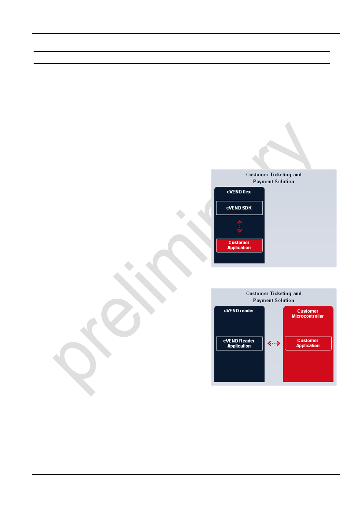
cVEND plug is available in two versions:
cVEND plug flex
The cVEND plug flex is a flexible secure platform to
develop a payment and ticketing solution. Due to the
variety of interfaces and the open SDK cVEND plug
flex can be the core element for a terminal. direct
connection of color or monochrome displays, touch
screens, external scanners or other peripheral components are possible.
cVEND plug reader
The cVEND plug reader is a secure contactless
reader for payment and ticketing applications which
includes an EMVCo contactless Level 2 kernel for
credit card processing. The cVEND plug reader offers an easy to use secure protocol and can be used
in payment mode as well as in transparent card
reader mode which makes it suitable for payment
and ticketing applications.
Page 6
Installation
cVEND plug
FEIG ELECTRONIC GmbH
Page 6 of 24
cVEND plug - User manual.docx
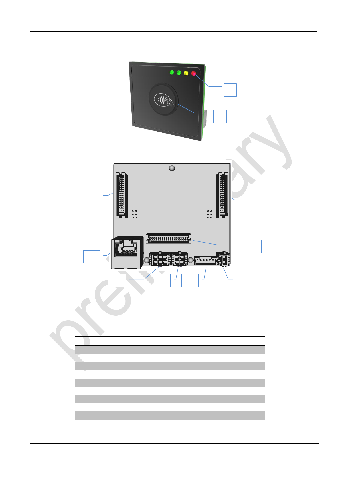
Label
Description
1
LEDs (4 x green, 1 x yellow, 1 x red)
2
From outside visible, illuminated plastic dome “Plug”
X1
Ethernet Interface (10 / 100 Base-T network port)
X2
USB Device Interface
X3
RS232 V.24 (UART#1) Interface
X4
RS232-LVTTL (UART#0) Interface
X5
Power Supply 5V DC
X6
Connector for RGB Display (cVEND plug flex only)
X11
Connector for SAM / SD-Card Extension Board
X12
Connector for Auxiliary Interfaces
1 2 X11
X2
X1
X6
X12
X4
X5
X3
Fig. 1: cVEND plug front view - not installed
Fig. 2: cVEND plug rear view - not installed
Table 1: Interfaces and connectors
Page 7
Installation
cVEND plug
FEIG ELECTRONIC GmbH
Page 7 of 24
cVEND plug - User manual.docx
3.
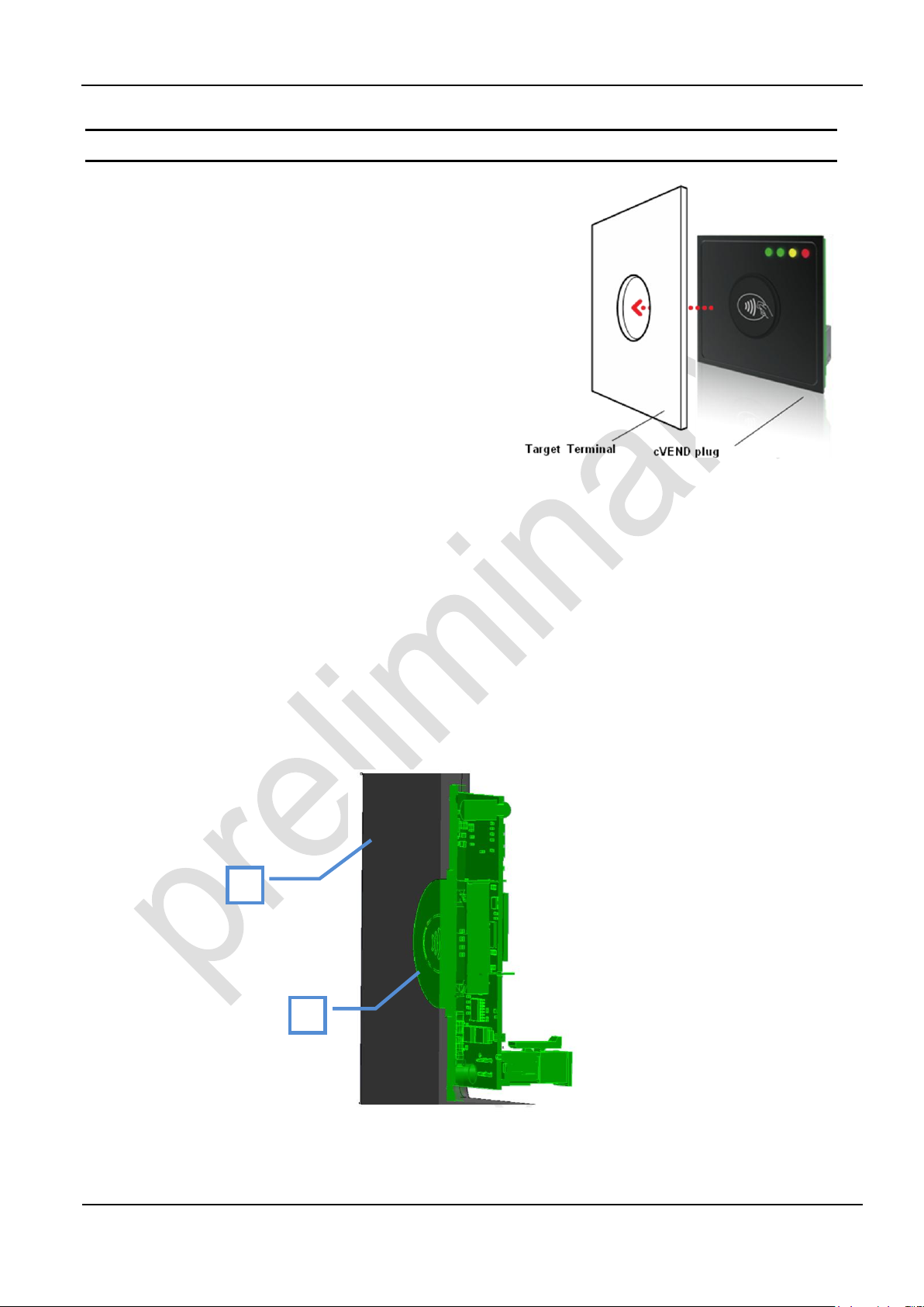
2
1
Mechanical Integration
For flush integration into non conducting housings one
round opening with a diameter of 28,5 mm is necessary to show the back-lit contactless symbol. cVEND
plug is installed from inside the housing. cVEND plug
is designed for front plates with 3 mm thickness.
cVEND plug has to installed from inside the housing. If
the LEDs of cVEND plug shall be used, additional light
channels are to be provided.
NOTICE
To comply with EMVCo regulations:
The contactless logo must be visible.
The upper edge of the cVEND plug plastic dome and the target terminal front plate
must be on the same level.
Avoid any kind of conducting material surrounding the cVEND plug.
Do not use conducting materials for fastening.
The following figure shows cross-sectional view of cVEND plug plastic dome (1) flush installed into
target terminal front plate (2)
Fig. 3: cVEND plug (1) installed in front plate (2) - cross-sectional view
Page 8
Installation
cVEND plug
FEIG ELECTRONIC GmbH
Page 8 of 24
cVEND plug - User manual.docx
1
3
2
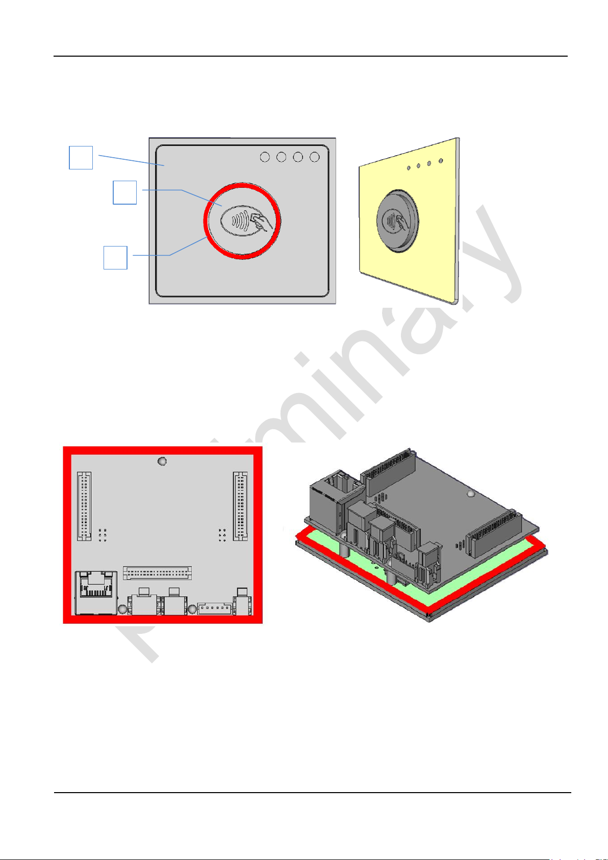
The cVEND plug front consists of a silicon rubber mat (1) with integrated sealing (2) and a fixed
poly carbonate plastic dome (3) which shows the back-lit contactless symbol.
Fig. 4: Plug front with sealing (red colored)
For fastening the cVEND plug front has to be pressed tight against the housing front. Therefore a
clamp range of 2,5 mm (fastening area) on all sides of the cVEND plug antenna PCB is available.
The following figure shows the clamp range (red marked). The picture on the left side shows the
back view, the picture on the right side is perspective view. For detailed dimension see Chapter
3.1. Dimensions. 3D STEP Data are available on request.
Fig. 5: cVEND plug fastening area (red marked)
Page 9

Installation
cVEND plug
FEIG ELECTRONIC GmbH
Page 9 of 24
cVEND plug - User manual.docx
3.1.
Dimensions
Fig. 6: cVEND plug front with LED position
Fig. 7: cVEND plug rear and side view (without cVEND SAM Extension Board)
Page 10

Installation
cVEND plug
FEIG ELECTRONIC GmbH
Page 10 of 24
cVEND plug - User manual.docx
4.
SAM1
SAM2
SAM3
SAM4
µSD
X6
1
38
38
1
6 5 4
3 2 1
4 3
2 1
2
1
1 2 3 4 5 6
X1
X11
X2
X3
X4
X5
X12
1
38
Connection
The connector I/O PINs are described from the cVEND plug view. A cVEND plug input must be
connected to one output or vice versa.
Fig. 8: cVEND plug - connector location
Fig. 9: cVEND plug with optional SAM Extension Board
Page 11

Installation
cVEND plug
FEIG ELECTRONIC GmbH
Page 11 of 24
cVEND plug - User manual.docx
4.1.
PIN
Label
1
TX+
2
TX-
3
RX+
4
VETH+
5
VETH+
6
RX-
7
VETH-
8
VETH-
Connector X1 - Ethernet Interface
cVEND has an integrated 10 / 100 Base-T network port at RJ45 connector X1, with automatic polarity correction during auto-negotiation and 10 Base-T signal reception.
CAT 5 cables are recommended to ensure a reliable operation at 10 Mbps or 100 Mbps.
Fig. 10: Ethernet Interface at connector X1
Required Connector: RJ45
Table 2: Pin Assignment Ethernet Connector
Page 12

Installation
cVEND plug
FEIG ELECTRONIC GmbH
Page 12 of 24
cVEND plug - User manual.docx
4.2.
PIN
Label
Direction
1
DEV-Vcc
I
2
DEV-D-
I/O 3 DEV-D+
I/O 4 N.C.
-
5
GND
- 6 Shield
-
Connector X2 - USB Device Interface
At connector X2 a USB-Device interface is provided where USB-Host can be connected. cVEND is
designed as a self powered device. powering over USB interface is not possible.
Fig. 11: USB Interface at connector X2
Required Connector:
The fitting complement for this connector consists of a 6-pole plug Type Molex Micro Fit
and the appending Crimp contact.
Manufacturer ordering code:
Molex 43025-0600
Plug, 6-pole, grid dimension 3.0 mm, Dual Row, Molex Micro Fit housing
Molex 43030-0001
Crimp contact, Female, grid dimension 3.0 mm, AWG#20-24, Molex Micro Fit
Table 3: Pin Assignment USB Connector
NOTE:
The USB interface is specified for max. 5 m (16,4 ft) cable length.
Page 13

Installation
cVEND plug
FEIG ELECTRONIC GmbH
Page 13 of 24
cVEND plug - User manual.docx
4.3.
PIN
Label
Direction
Remark
1
Device TXD
O
2
Device RXD
I
3
Wake-UP
I/O
see 4.6. Wake-Up
4
GND
-
Connector X3 - RS232 V.24 (UART#1) Interface
X3 is the connector for a RS232 interface on V.24 level.
Fig. 12: RS232 V.24 (UART#1) Interface at connector X3
Required Connector:
The fitting complement for this connector consists of a 4-pole plug Type Molex Micro Fit
and the appending Crimp contact.
Manufacturer ordering code
Molex 43025-0400
Plug, 4-pole, grid dimension 3.0 mm, Dual Row, Molex Micro Fit housing
Molex 43030-0001
Crimp contact, Female, grid dimension 3.0 mm, AWG#20-24, Molex Micro Fit
Table 4: Pin Assignment RS232 V.24 Interface
Page 14

Installation
cVEND plug
FEIG ELECTRONIC GmbH
Page 14 of 24
cVEND plug - User manual.docx
4.4.
PIN
Label
Direction
1
Device RTS
O
2
GND
-
3
Device RXD
I
4
Device TXD
O
5
Device CTS
I
6
Wake-Up
I/O
see 4.6. Wake-Up
Connector X4 - RS232-LVTTL (UART#0) Interface
At connector X4 a RS232 interface on LVTTL 3.3V level is provided. This interface offers also
hardware handshake.
Fig. 13: RS232-LVTTL Interface at connector X4
Required Connector:
The fitting complement for this connector consists of a 6 -pole plug Type JST PH and the
appending Crimp contact.
Manufacturer ordering code:
JST PHR-6 - housing, 6-pole, grid dimension 2.0 mm, Single Row
JST SPH-002T-P0.5 or SPH-004T-P0.5 Crimp contact
Table 5: Pin Assignment RS232 LVTTL Interface
NOTE:
The length of the cable to the RS232-LVTTL interface should be kept as short as possible,
and must in any case not exceed 3 m.
Page 15

Installation
cVEND plug
FEIG ELECTRONIC GmbH
Page 15 of 24
cVEND plug - User manual.docx
4.5.
PIN
Label
Direction
Remark
1
Vcc
I
5,0 V/DC
2
GND
-
Connector X5 – Power Supply Vcc
cVEND must be supplied by a regulated power supply of 5 V DC only. If switching power supplies
are used be sure that there is adequate filtering. Noise from the power supply can result in a reduction of the read/write range of the module. The cable length from the power supply should be as
short as possible, and should in any case not exceed 3 m.
Fig. 14: Power Supply at connector X5
Required Connector:
The fitting complement for this connector consists of a 2-pole plug Type Molex Micro Fit
and the appending Crimp contact.
Manufacturer ordering code
Molex 43025-0200
Plug, 2-pole, grid dimension 3.0 mm, Dual Row, Molex Micro Fit housing
Molex 43030-0001
Crimp contact, Female, grid dimension 3.0 mm, AWG#20-24, Molex Micro Fit
Table 6: Pin Assignment Power Supply
NOTE:
The reader has to be supplied by a limited power supply (e.g. NEC Class 2/LPS power sup-
ply) according IEC EN 60950-1 chapter 2.5, only.
Reversing the polarity of the supply voltage may destroy the device.
Supply voltages outside the specifications may destroy the device.
Page 16

Installation
cVEND plug
FEIG ELECTRONIC GmbH
Page 16 of 24
cVEND plug - User manual.docx
4.6.
Wake-Up
cVEND offers a standby mode whic can be configured via software commands. If standby is activated the bidirectional Wakeup I/O is used for signaling a wakeup event by the cVEND and can be
used by the host to activate the cVEND.
Wakeup by host:
The host controller can awake the cVEND by pulling down the Wakeup line.
Fig. 15: cVEND internal Wake-up circuit
NOTE:
If the standby - wakeup option is used in connection with the USB interface the USB con-
nection will be interrupted while standby mode.
Page 17

Installation
cVEND plug
FEIG ELECTRONIC GmbH
Page 17 of 24
cVEND plug - User manual.docx
4.7.
4.7.1.
Connector X6, X11, X12 - Extension Interfaces
Via X11 and X12 the optional extension board, which offers 4 sockets for SAM cards and one
socket for a SD memory card, can be connected.
Alternatively X11 and X12 can be used to connect custom specific electronics. therefore this connectors are offering signals to connect external smart card drivers, SD memory cards, digital I/Os
and I2C, SPI and USB Host interfaces. Further technical details, implementation recommendations
and schematics are available on request.
NOTICE:
Some of the Extension Interfaces may need a dedicated software driver which may not provided by the standard cVEND SDK.
Connector X6 - RGB Display (cVEND plug flex only)
X6 is intended for connecting an external custom specific RGB Display. technical details are available on request.
Fig. 16: cVEND plug X6 - PIN assignment.
Page 18

Installation
cVEND plug
FEIG ELECTRONIC GmbH
Page 18 of 24
cVEND plug - User manual.docx
4.7.2.
4.7.3.
Connector X11 - SAM and SD Interface
Fig. 17: cVEND plug X11 - PIN assignment.
Connector X12 - Auxiliary Interfaces
Fig. 18: cVEND plug X12 - PIN assignment.
Page 19

Installation
cVEND plug
FEIG ELECTRONIC GmbH
Page 19 of 24
cVEND plug - User manual.docx
5.
flex
reader
Housing
plug front with contactless symbol (visible dome: PC; plane:
Silicon)
Dimensions over all (W x H x D)
Dimensions visible
79 x 70 x 37 mm
28.5 mm
Wight
85 g
Temperature Range
Operating
Storage
-25 °C to +70 °C ambient temperature
-25 °C to +80 °C
Humidity
95 % max, (no condensing)
Power Supply
5,0 to 5,5 V DC (Ripple < 80 mVpp)
Power Consumption Operation
typ. < 1 A, peripherals excluded
Standby Mode
< 20 mA, Full operation after wake-up 1 Sec
Wakeup by Card and digital input
RFID Interface
Integrated Antenna
13,56 MHz
ISO/IEC 14443-A / -B (NFC reader/writer mode) in EMVCo
contactless mode
JIS X 6319-4 (Sony Felica) transparent communication channel
NFC IP1 (P2P) and NFC card emulation mode hardware
enabled
Supported Transponder
ISO/IEC 14443-4 compliant smart cards, NFC Type 1, 2 and 4
in card emulation mode, mifare classic, mifare ultralight and further technologies on request
Peripheral Interfaces
Ethernet - IEEE 802.3/Ethernet, 10/100 Mbps
RS232 (V.24)
RS232-LVTTL, incl. CTS, RTS signals
USB 2.0 Host hardware enabled
USB 2.0 Device
SPI hardware enabled
I2C 100/400 kHz hardware enabled
24-Bit RGB-bus interface for external TFT displays hardware
enabled
User Interface
6 LED (4 green, 1 red, 1 yellow), Buzzer,
illuminated Payment Logo
CPU and Security
ARM 9 CPU (384 MHz) – Tamper Protected and Side Channel
Attack Resistant with Real Time Memory Encryption
Cryptographic Hardware Acceleration supports
SHA, DES, AES
True Random Number Generator
RAM MByte 128 / FLASH MByte 256
Real Time Clock – Battery backed
Battery
3V Lithium Battery, 540 mAh, Lifetime 10 year at 25 °C1
1
Technical Data
Battery is needed for security function and RTC. Higher temperature will reduced lifetime!
Page 20

Installation
cVEND plug
FEIG ELECTRONIC GmbH
Page 20 of 24
cVEND plug - User manual.docx
5.1.
Radio Approval
Europe
USA
Canada
EN 300 330
FCC 47 CFR Part 15
IC RSS-Gen, RSS-210
EMC
EN 301 489
Safety and Health
EN 60950
EN 50364
Hazardous Substances
RoHS - 2011/65/EC
Electrostatic Discharge
ISO 10605, Category 3
Protection Class (Front Side)
IP65 (if accurate installed)
Impact protection Class
IEC 62262, IK10 (installed in equivalent robust housing)
Shock and Vibration
IEC 60721-3-5, Class 5M3
Payment
EMVCo 2.4 Contactless Level 1
PCI PTS 4.x, SRED incl. Open Protocol
Contactless Payment Kernel (Optional)
MasterCard PayPass
VISA Paywave
American Express Expresspay
Discover
5.2.
5.2.1.
Standard Compliance
Radio Approvals
Europe (CE)
When properly used this radio equipment conforms to the essential requirements of Article 3 and
the other relevant provisions of the R&TTE Directive 1999/5/EC of March 99.
Performance Classification according to ETSI EN 301 489: Class 2
Page 21

Installation
cVEND plug
FEIG ELECTRONIC GmbH
Page 21 of 24
cVEND plug - User manual.docx
5.2.2.
Product name:
cVEND plug
FCC ID:
IC:
PJMcVEND
6633A-cVEND
Notice for USA and
Canada
This device complies with Part 15 of the FCC Rules and with
RSS-210 of Industry Canada.
Operation is subject to the following two conditions.
(1) this device may not cause harmful interference, and
(2) this device must accept any interference received,
including interference that may cause undesired operation.
Unauthorized modifications may void the authority granted under
Federal communications Commission Rules permitting the operation
of this device.
This equipment has been tested and found to comply with the limits for
a Class A digital device, pursuant to Part 15 of the FCC Rules. These
limits are designed to provide reasonable protection against harmful
interference when the equipment is operated in a commercial
environment. This equipment generates, uses, and can radiate radio
frequency energy and, if not installed and used in accordance with the
instruction manual, may cause harmful interference to radio
communications. Operation of this equipment in a residential area is
likely to cause harmful interference in which case the user will be
required to correct the interference at his own expense.
Le présent appareil est conforme aux CNR d'Industrie Canada applicables aux appareils radio exempts de licence. L'exploitation est autorisée aux deux conditions suivantes :
(1) l'appareil ne doit pas produire de brouillage, et
(2) l'utilisateur de l'appareil doit accepter tout brouillage radioélectrique
subi, même si le brouillage est susceptible d'en compromettre le fonctionnement.
USA (FCC) and Canada (IC)
Warning: Changes or modification made to this equipment not expressly approved by
FEIG ELECTRONIC GmbH may void the FCC authorization to operate this equipment.
Installation with FCC / IC Approval:
FCC-/IC-NOTICE: To comply with FCC Part 15 Rules in the United States / with IC Radio Standards in Canada, the system must be professionally installed to ensure compliance with the Part 15
certification / IC certification. It is the responsibility of the operator and professional installer to ensure that only certified systems are deployed in the United States / Canada.
Page 22

Installation
cVEND plug
FEIG ELECTRONIC GmbH
Page 22 of 24
cVEND plug - User manual.docx
Page 23

Installation
cVEND plug
FEIG ELECTRONIC GmbH
Page 23 of 24
cVEND plug - User manual.docx
6.
SAM1
SAM2
SAM3
SAM4
µSD
µSD
X20
cVEND plug SAM Extension - Option
The optional SAM Extension board offers 4 sockets for ID000 Format smart cards and one SDHC
memory card socket. It can be connected to cVEND plug via connector X11 and X12.
Fig. 19: cVEND plug SAM Extension - top view
Fig. 20: cVEND plug SAM Extension - bottom view
Page 24

Installation
cVEND plug
FEIG ELECTRONIC GmbH
Page 24 of 24
cVEND plug - User manual.docx
Removal Memory
microSD Socket
SD Host Controller Version 2.0
for SD/SDHC class 10 memory card
SAM Interface - ISO7816
4 x SAM Sockets for ID000 Format (SIM-Card)
T=0 and T=1 Protocol
support of power class A, B, C
X20: Auxiliary Interfaces
Via the 20 pol. FFC/FCP, RM 0,6 connector X20 the SPI, RS232-LVTTL, USB-Host and
I2C interfaces as well as digital GPIOs are provided.
NOTICE:
Some interfaces may need a dedicated software driver which may not provided by
the standard cVEND SDK.
Fig. 21: cVEND plug SAM Extension - X20 Pin assignment
 Loading...