

Page 1
ID CPRPOS
INSTALLATION
Card reader for contactless and contact smart cards
final – public (B)
2015-07-27 – ID
CPRPOS User Manual-01.doc
Page 2

OBID® classic-pro
Installation
ID CPRPOS
Note
Copyright 2015 by
FEIG ELECTRONIC GmbH
Lange Strasse 4
D-35781 Weilburg
Tel.: +49 6471 3109-0
http://www.feig.de
With the edition of this document, all previous editions become void. Indications made in this manual may be
changed without previous notic e.
The reproduction, distribution and utilization of this document as well as the communication of its contents to others
without express authorization is prohibited. Offenders will be held liable for the payment of damages. All rights reserved
in the event of the grant of a patent, utility model or design.
Composition of the information in this document has been done to the best of our knowledge. FEIG
ELECTRONIC GmbH does not guarantee the correctness and completeness of the details given in this
manual and may not be held liable for damages ensuing from incorrect or incomplete information. Since,
despite all our efforts, errors may not be completely avoided, we are always grateful for your useful tips.
The instructions given in this manual are based on advantageous boundary conditions. FEIG ELECTRONIC
GmbH does not give any guarantee promise for perfect function in cross environments and does not give
any guaranty for the functionality of the complete system which incorporates the subject of this document.
FEIG ELECTRONIC call explicit attention that devices which are subject of this document are not designed
with components and testing methods for a level of reliability suitable for use in or in connection with surgical
implants or as critical components in any life support systems whose failure to perform can reasonably be
expected to cause significant injury to a human. To avoid damage, injury, or death, the user or application
designer must take reasonably prudent steps to protect against system failures.
FEIG ELECTRONIC GmbH assumes no responsibility for the use of any information contained in this
document and makes no representation that they free of patent infringement. FEIG ELECTRONIC GmbH
does not convey any license under its patent rights nor the rights of others.
®
and OBID myAXXESS® is a registered trademark of FEIG ELECTRONIC GmbH.
OBID
All brand names, trademarks or logos are property of their respective owners.
FEIG ELECTRONIC GmbH Page 2 of 18
ID CPRPOS User Manual-01.doc
Page 3

OBID® classic-pro
Installation
ID CPRPOS
Contents
1. Safety Instructions / Warning - Read before start-up ! 4
2. Characteristics of the ID CPRPOS 5
2.1. Scope of delivery ............................................................................................................... 5
2.2. Available accessories and spare parts ............................................................................ 6
3. Dimensions 7
4. Connections 8
4.1. Ethernet interface .............................................................................................................. 9
4.2. USB interface ................................................................................................................... 10
4.3. RS232 interface / Power supply ...................................................................................... 11
5. Display and LED 12
5.1. Display ............................................................................................................................. 12
5.2. LED ................................................................................................................................... 13
6. Installation of a Secure Access Module (SAM) 14
7. Radio Approvals 15
7.1. Europe (CE) ...................................................................................................................... 15
7.2. USA (FCC) and Canada (IC) ............................................................................................ 15
8. Technical Data 17
FEIG ELECTRONIC GmbH Page 3 of 18
ID CPRPOS User Manual-01.doc
Page 4

OBID® classic-pro
Installation
ID CPRPOS
1. Safety Instructions / Warning - Read before start-up !
• The device may only be used for the intended purpose designed by for the manufacturer.
• The operation manual should be conveniently kept available at all times for each user.
• Unauthorized changes and the use of spare parts and additional devices which have not been
sold or recommended by the manufacturer may cause fire, electric shocks or injuries. Such
unauthorized measures shall exclude any liability by the manufacturer.
• The liability-prescriptions of the manufacturer in the issue valid at the time of purchase are valid
for the device. The manufacturer shall not be held legally responsible for inaccuracies, errors,
or omissions in the manual or automatically set parameters for a device or for an incorrect
application of a device.
• Repairs may only be executed by the manufacturer.
• Installation, operation, and maintenance procedures should only be carried out by qualified
personnel.
• Use of the device and its installation must be in accordance with national legal requirements
and local electrical codes .
• When working on devices the valid safety regulations must be observed.
• Special advice for carriers of cardiac pacemakers:
Although this device doesn't exceed the valid limits for electromagnetic fields you should keep
a minimum distance of 25 cm between the device and your cardiac pacemaker and not stay in
an immediate proximity of the device respective the antenna for some time.
FEIG ELECTRONIC GmbH Page 4 of 18
ID CPRPOS User Manual-01.doc
Page 5
OBID® classic-pro
Installation
ID CPRPOS
2. Characteristics of the ID CPRPOS
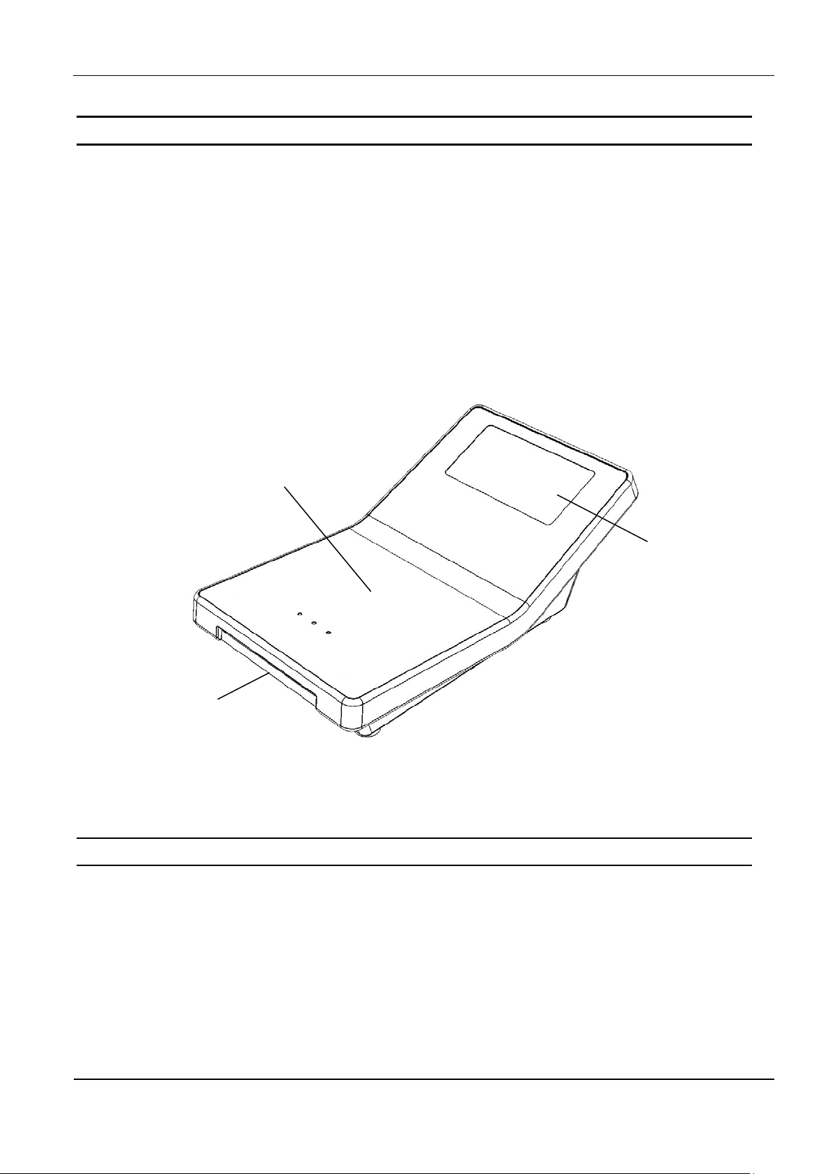
The I D CPRPOS is a smart card reader for contactless and contact smart car ds according to ISO
14443-A/B and ISO 7816. The reader is designed as deskt op device and is due to the suppor t of
different chip t ypes like mifare classic, mifare DESFire and mifare PLUS suitable for a wide range
of applications. In addition to the contact based smart c ard interface for ID-1 sized smart car ds t he
ID CPRPOS has one SAM socket for ID-000 sized smart cards available.
The ID CPRPO S can be connected and controlled by a host system via its RS232, USB or Ethernet interface. A connected host system is able to use the ID CPRPOS to communicate with smart
cards and to control the user guidance via display, LED and buzzer. T he reader could be configured by the connected host system, too.
contactless
smart card interface
contact
smart card interface
Figure 1: Surface of the ID CPRPOS
2.1. Scope of delivery
The scope of delivery includes following components:
• 1 x Electronic unit ID CPRPOS
display
• 1 x Power supply unit
• 1 x USB connection cable
• 1 x Wire strap
FEIG ELECTRONIC GmbH Page 5 of 18
ID CPRPOS User Manual-01.doc
Page 6

OBID® classic-pro
Installation
ID CPRPOS
Power supply unit (5 V DC / 1 A); Length of the connection
2.2. Available accessories and spare parts
Table 1: Available accessories and spare parts
Order Number Article Description
4219.000.00
4218.000.00 ID CAB.RS-C
OBID myAXXESS
ID NET.5V-EU
cable: 1,5 m
RS232 connection cable incl. connector for power supply
- Host connector: D-SUB 9 poles
- Device connector: RJ-12 plug 6 poles
- Power supply connector: RJ-12 jack 6 poles
- Length: 2,0 m
FEIG ELECTRONIC GmbH Page 6 of 18
ID CPRPOS User Manual-01.doc
Page 7

OBID® classic-pro
Installation
ID CPRPOS
3. Dimensions
The ID CPRPOS is designed as desktop device. Its small form factor offers the possibility to place
the reader directly on a sales counter or at a cashier station. Due to its rubber feet the reader is
suitable for slippery undergrounds.
Figure 2: Top view
Figure 3: Side view
FEIG ELECTRONIC GmbH Page 7 of 18
ID CPRPOS User Manual-01.doc
Page 8

OBID® classic-pro
Installation
ID CPRPOS
4. Connections
Figure 4: ID CPRPOS - position of the connectors
Ethernet interface (RJ-45)
USB interface (Mini-USB)
RS232 interface and power supply (RJ-12)
NOTE:
Only one host interface should be used at the same time. The usage of more than one host
interface at the same time can cause malfunctions.
FEIG ELECTRONIC GmbH Page 8 of 18
ID CPRPOS User Manual-01.doc
Page 9

OBID® classic-pro
Installation
ID CPRPOS
4.1. Ethernet interface
The ID CPRPOS has an integrated 10/100 base-T network port with a common RJ-45 connector
and an automatic “crossover correction”.
With structured cabling CAT5 cables should be used. This ensures a reliable operation at 10 Mbps
and 100 Mbps.
The prerequisite for using TCP/IP protocol is that each device has a unique address on the network. All readers have a factory set IP address. The communication parameter could be configured
user-defined.
Table 2: Standard factory configuration of the ethernet interface
Network Address
IP address 192.168.10.10
Subnet mask 255.255.0.0
Port 10001
DHCP OFF
NOTE:
• The reader is equipped with a DHCP ready ethernet interface.
• It is recommended to use a screened STP (shielded twisted pair) CAT5 cable.
FEIG ELECTRONIC GmbH Page 9 of 18
ID CPRPOS User Manual-01.doc
Page 10

OBID® classic-pro
Installation
ID CPRPOS
4.2. USB interface
The ID CPRPOS is equipped with a USB on-the-go interface (USB mini jack). It allows a direct
connection to a host system for controlling, configuration and firmware update of the device (ID
CPRPOS is USB slave). In addition the ID CPRPOS offers the possibility to connect an external
USB memory stick to the electronic unit by means of a USB on-the-go adaptor (ID CPRPOS is
USB master).
Figure 5: USB mini jack
Figure 6: USB mini cable for host connection
With the delivered wire strap the USB cable could be fixed at the housing and a strain relief for the
cable connection could be established.
NOTE:
The device needs a separate power supply via the RJ-12 jack. A power supply of the device
via the USB interface is not supported.
FEIG ELECTRONIC GmbH Page 10 of 18
ID CPRPOS User Manual-01.doc
Page 11

OBID® classic-pro
Installation
ID CPRPOS
6
1
4.3. RS232 interface / Power supply
Figure 7: Pin assignment RJ-12 jack
Table 3: Pin assignment RJ-12 jack
Pin No. Name Function
1 Vcc 5 V DC, approx. 500 mA
2 RS232-RxD
RS232 interface
3 RS232-TxD
4 nc not connected
5 nc not connected
6 GND Ground
By using USB or Ethernet as communication interface the power supply unit included could be
directly connected to the RJ-12 jack of the device.
For usage of the RS232 interface a special RS232 connection cable is available (see 2.2. Available
accessories and spare parts). In that case the included power supply unit has to be connected to
the RJ-12 jack of the connection cable. The RJ-12 plug of the connection cable has to be connected to the RJ-12 jack of the device.
CAUTION:
The device has to be supplied by a limited power supply (e.g. NEC Class 2/LPS power sup-
ply) according IEC EN 60950, only!
Reversing the polarity of the supply voltage may destroy the device.
FEIG ELECTRONIC GmbH Page 11 of 18
ID CPRPOS User Manual-01.doc
Page 12

OBID® classic-pro
Installation
ID CPRPOS
5. Display and LED
LED
display
Figure 8: Display and LED
The ID CPRPOS is equipped with a display as well as LED for user guidance and to show status
information.
5.1. Display
A connected host system can send text messages via the interfaces RS232, USB, and Ethernet to
the integrated graphic display to realise a user guidance. Customised graphics (monochrome Bitmaps with size 128 x 64 dots; e.g. company logo or advertisement) could be stored in the device
and could be shown outside the user guidance. For further information please read the system
manual H31010-xx-ID-B.pdf.
Note:
With temperatures below -10 °C the display contents could be shown slower.
FEIG ELECTRONIC GmbH Page 12 of 18
ID CPRPOS User Manual-01.doc
Page 13

OBID® classic-pro
Installation
ID CPRPOS
5.2. LED
The three LEDs of the ID CPRPOS indicate the status of the device for the user. The device is
equipped with 1 green, 1 yellow, and 1 red LED.
Figure 9: Position of the LED on the ID CPRPOS
Table 4: LED on the ID CPRPOS
LED Description
green
red
yellow
Communication with a contactless smart card
Error
-
In table 4 the meaning of the LEDs with standard configuration is de scribed. T he LED could be
controlled by a connected host system and a customized LED indication is possible.
FEIG ELECTRONIC GmbH Page 13 of 18
ID CPRPOS User Manual-01.doc
Page 14

OBID® classic-pro
Installation
ID CPRPOS
6. Installation of a Secure Access Module (SAM)
To install a secure access module (SAM) the bottom part of the housing has to be opened. After
removing the 4 screws the bottom part of the housing could be opened.
Figure 10: Opening of the housing
A socket is located on the PCB in which the SAM can be plugged in. To open the socket the cover
of the socket has to be pushed slightly in direction “OPEN”. Afterwards it can be lifted. The SAM
has to be inserted according Figure 11: Installation of a SAM. The golden contacts of the chips are
facing towards the PCB when the socket is closed. After the socket is closed it has to be locked
again by pushing it slightly towards in direction “CLOSE”. Afterwards the housing could be closed
and the screws could be replaced.
NOTE:
The maximum tightening torque of the housing screws is 0,30 Nm.
FEIG ELECTRONIC GmbH Page 14 of 18
Figure 11: Installation of a SAM
ID CPRPOS User Manual-01.doc
Page 15

OBID® classic-pro
Installation
ID CPRPOS
ts for a Class A
an
Operation of this equipment in a residential area is likely to cause harmful
me si le brouillage est susceptible d'en compromettre le fonctionnement.
7. Radio Approvals
7.1. Europe (CE)
When used according to regulation, this radio equipment conforms with the basic requirements of
Article 3 and the other relevant provisions of the R&TTE Guideline 1999/EC dated March 99.
Equipment Classification according ETSI EN 300 330: Class 2
7.2. USA (FCC) and Canada (IC)
Product name:
FCC ID:
IC:
Notice for USA
and Canada
This device complies with Part 15 of the FCC Rules and with
RSS-210 of Industry Canada.
Operation is subject to the following two conditions.
(1) this device may not cause harmful interference, and
(2) this device must accept any interference received,
including interference that may cause undesired operation.
Unauthorized modifications may void the authority granted under Federal
communications Commission Rules permitting the operation of this device.
This equipment has bee n tested and f ound to compl y with the limi
digital device, pursuant to Part 15 of the FCC Rules. T hese limits ar e designed to
provide reasonable protec tion against harm ful interference when th e equipment is
operated in a comm ercial environment. T his equipment generat es, uses, and c
radiate radio frequenc y energy and, if not installed and used in accordance with
the instruction manual, may cause harmful inter ference to radio comm unications.
interference in w hich case the user will be re quired to correct the int erference at
his own expense.
Le présent appareil est conforme aux CNR d'Industrie Canada applicables aux
appareils radio exempts de licence. L'exploitation est autorisée aux deux conditions suivantes :
(1) l'appareil ne doit pas produire de brouillage, et
(2) l'utilisateur de l'appareil doit accepter tout brouillage radioélectrique subi, mê-
ID CPRPOS
PJMCPRPOS
6633A-CPRPOS
FEIG ELECTRONIC GmbH Page 15 of 18
ID CPRPOS User Manual-01.doc
Page 16

OBID® classic-pro
Installation
ID CPRPOS
Warning: Changes or modification made to this equipment not expressly approved by
FEIG ELECTRONIC GmbH may void the FCC authorization to operate this equipment.
Installation with FCC / IC Approval:
FCC-/IC-NOTICE: To comply with FCC Part 15 Rules in the United States / with IC Radio Standards in Canada, the system must be professionally installed to ensure compliance with the Part 15
certification / IC certification. It is the responsibility of the operator and professional installer to ensure that only certified systems are deployed in the United States / Canada.
FEIG ELECTRONIC GmbH Page 16 of 18
ID CPRPOS User Manual-01.doc
Page 17

OBID® classic-pro
Installation
ID CPRPOS
ID CPRPOS
Dimensions
92 mm x 161 mm x 58 mm
Protection class
IP20
storage
Relative air humidity
max. 95 %
Supply voltage
Current consumption
approx. 500 mA
Operating frequency
13,56 MHz
Antenna
internal
Power Class A, B, C
RS232
Ethernet
10BASE-T/100BASE-TX; MDI/MDI-X cross over detection; IPv4
Acoustic indicator
write cycles 100.000
8.Technical Data
Table 5: Technical Data
Housing
Weight
Temperature range
Contactless smart card interface
Supported transponder types (contactless)
(Read and Write)
ID-1
Contact
smart card interface
ID-000
operation
plastic
approx. 250 g
-20 °C up to +70 °C (-4 °F up to +158 °F)
-30 °C up to +80 °C (-22 °F up to +176 °F)
+5 V DC ± 5 %
tested according to EM VC o Conta ctle ss Level 1
ISO/IEC 14443-4,
NFC card emulation mode Type 1, 2, 4, mifare classic, mifare
PLUS, mifare DESFire, mifare ultralight, my-d mov e, my -d prox-
imity, SR176, SRIx, Calypso (Innovatron radio protocol)
tested according to EMVCo Contact Level 1;
landing contacts; 200 000 cycles
SAM socket; ISO 7816; 9600 up to 625.000 Bit/s
T=0 and T=1 protocol
USB
Interfaces
Optical indicator
Flash memory
Mini-USB-Jack; Self powered device
4.800 - 921.600 Baud; RJ-12-Jack
1 x LED red; 1 x LED yellow; 1 x LED green
FEIG ELECTRONIC GmbH Page 17 of 18
graphic LCD, 128 x 64 dots
1 internal buzzer
2 MByte
ID CPRPOS User Manual-01.doc
Page 18

OBID® classic-pro
Installation
ID CPRPOS
Canada IC RSS-Gen, RSS-210
EMC
Environmental (shock, vibration, climate)
IEC 60068
Function
tested according to EMVCo Contactless/Contact Level 1
Radio Approval
Europe EN 300 330
USA FCC 47 CFR Part 15
EN 301 489
Health and Safety
Waste and Hazardous Substances
EN 60950
EN 50364
WEEE - 2002/96/EC
RoHS - 2011/65/EC
FEIG ELECTRONIC GmbH Page 18 of 18
ID CPRPOS User Manual-01.doc
 Loading...