


FEDDERS
LARGE SPLIT UNIT (R407C)
SERVICE MANUAL
ISSUED ON 1 APRIL,2003

SECTION A: SPECIFICATIONS
SECTION B: PARTS LIST AND EXPLODED VIEWS
SECTION C: INSTALLATION
SECTION D: TROUBLE SHOOTING
SECTION E: WIRING DIAGRAM
SECTION F: TECHNICAL DATA

SECTION A: SPECIFICATIONS
FEDDERS LARGE SPLIT (R407C)
MODEL NUMBER
Indoor unit E1FE418N6D EHFE418N6D E1FE424N6D EHFE424N6D
PERFORMANCE DATA
UNIT DIMENSIONS - mm (inch)
CARTON DIMENSIONS mm (inch)
WEIGHTS - kg (lb)
CONTAINER LOADING
Outdoor unit E1FC418N6G EHFC418N6G E1FC424N6G EHFC424N6G
Volts / Hz / Phase 220-240 / 50 / 1 220-240 / 50 / 1 220-240 / 50 / 1 220-240 / 50 / 1
Cooling - BTU/h (kW) 17500 (5.13) 17500 (5.13) 21500 (6.30) 21000 (6.16)
Heating - BTU/h (kW) -- 18300 (5.36) -- 22000 (6.45)
Amps (Cooling / Heating) 9.8 9.8/9.8 11.0 11.2/11.4
Watts (Cooling / Heating) 2060 0.95636026 2400 2400/2550
EER (Cooling) 8.5 8.5/8.4 8.8 8.4/8.6
Indoor Sound Level (dBA) 47 47 47 47
Moisture Removel (Litres/h) 3.0 3.0 3.5 3.5
Air Circulation - CMH (CFM) 850 850/920 830 830/920
Interconnecting Tubing 3/8" & 5/8" 3/8" & 5/8" 3/8" & 5/8" 3/8" & 5/8"
Maximum Tibing Length - m (ft) 15 (49.2) 15 (49.2) 15 (49.2) 15 (49.2)
Indoor Unit : Width 1020(40.16) 1020(40.16) 1020(40.16) 1020(40.16)
Depth 195(7.68) 195(7.68) 195(7.68) 195(7.68)
Height 320 (12.60) 320 (12.60) 320 (12.60) 320 (12.60)
Outdoor Unit : Width 895 (35.2) 895 (35.2) 895 (35.2) 895 (35.2)
Depth 331 (13.0) 331 (13.0) 331 (13.0) 331 (13.0)
Height 623 (24.6) 623 (24.6) 623 (24.6) 623 (24.6)
Indoor Unit : Width 1050(41.34) 1050(41.34) 1050(41.34) 1050(41.34)
Depth 290(11.42) 290(11.42) 290(11.42) 290(11.42)
Height 370(14.57) 370(14.57) 370(14.57) 370(14.57)
Outdoor Unit : Width 1070(42.13) 1070(42.13) 1070(42.13) 1070(42.13)
Depth 460(18.11) 460(18.11) 460(18.11) 460(18.11)
Height 735(28.94) 735(28.94) 735(28.94) 735(28.94)
Indoor Unit : Net Weight 14(30.8) 14(30.8) 14(30.8) 14(30.8)
Shipping Weight 18(39.6) 18(39.6) 18(39.6) 18(39.6)
Outdoor Unit : Net Weight 47(103.4) 47(103.4) 62(136.4) 62(136.4)
Shipping Weight 53(116.6) 53(116.6) 68(149.6) 68(149.6)
20 foot container 60 60 60 60
40 foot container 126 126 126 126
40 foot H.C. container 140 140 140 140
A1

SECTION B: PARTS LIST AND EXPLODED VIEWS

SPECIFICATIONS :
FEDDERS
LARGE SPLIT AIR CONDITIONER(R407C)
SERVICE PARTS LIST
INDOOR UNIT DIMENSIONS : 1020(40.15")W x 195(7.68")D x 320(12.60")H
OUTDOOR UNIT DIMENSIONS : 895(35.2")W x 331(13.0")D x 623(24.6")H
AT STANDARD AHAM
RATING CONDITIONS
R CHARGE
E EER GRAMS OF
MODEL V BTU/h (kW) MODE Volt / Hz Amps Watts COOL R-407C
E1FE418N6D - E1FC418N6G 17500 (5.13) COOL 220-240 / 50 9.8 2060 8.5 1.43 kg
EHFE418N6D - EHFC418N6G 17500 (5.13) COOL 220-240 / 50 9.8 2060 8.5 1.50 kg
18300 (5.36) HEAT 220-240 / 50 9.8 2154 8.4 --
E1FE424N6D - E1FC424N6G 21500 (6.30) COOL 220-240 / 50 11.0 2400 8.8 1.55 kg
EHFE424N6D - EHFC424N6G 21000 (6.16) COOL 220-240 / 50 11.2 2400 8.4 1.70 kg
22000 (6.45) HEAT 220-240 / 50 11.4 2550 8.6 --
REFRIGERANT
B1

EEEE1H1HFFFFEEEE444411228844NNN
N
Item6666
No.
Description
Service Part #
DDDD-----CHASSIS ASSEMBLY-----
MODEL NUMBER
FEDDERS
LARGE SPLIT
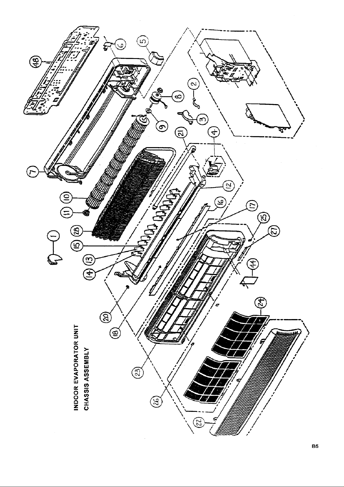
INDOOR EVAPORATOR UNIT
(R407C)
1 Lock Plate, Blower Wheel Left 36-08-00010-001 1 1 1 1
2 Lock Plate, Fan Motor, Right 36-08-00020-001 1 1 1 1
3 Lock Plate, Fan Motor, Left 36-08-00030-001 1 1 1 1
4 Motor, Discharge Cover 36-08-00050-001 1 1 1 1
5 Plate protect, Coil Water 36-08-00060-001 1 1 1 1
6 Tube Bracket 36-08-00070-001 1 1 1 1
7 Base Asm. 36-08-00080-001 1 1 1 1
(include PS base, reinforce plate
and insulation)
8 Fan Motor 35-16-90010-001 1 1 1 1
9 Grommet, Fan Motor 36-08-00100-001 2 2 2 2
10 Blower Wheel, Dia102x763lg, Antimould 36-08-00110-002 1 1 1 1
11 Blower Wheel Grommet Asm 36-08-00120-001 1 1 1 1
(include grommet, bearing)
12 Drip Tray 36-08-00130-001 1 1 1 1
(include PS and PE insulation
complete)
13 Air Deflector 36-08-00140-001 14 14 14 14
14 Handle Air Deflector 36-08-00150-001 2 2 2 2
15 Tie-bar, Air Deflector 36-08-00160-001 2 2 2 2
16 Discharge Cover 36-08-00170-001 1 1 1 1
17 Bearing, Discharge Cover, Mid 36-08-00180-001 2 2 2 2
18 Bearing, Discharge Cover, Left 36-08-00190-001 1 1 1 1
20 Plug, Drip Tray 36-08-00210-001 1 1 1 1
21 Drain Hose Asm. 36-08-00220-001 1 1 1 1
(include drain hose,insulation)
22 Decorative Front Grille,Neuter 36-08-00230-N01 1 1 1 1
23 Decorative Front Top Cover 36-08-00240-N01 1 1 1 1
B2
EEEE1H1HFFFFEEEE444411228844NNN
N
Item6666
No.
Description
Service Part #
DDD
D
MODEL NUMBER
-----CHASSIS ASSEMBLY(Cont')-----
-----REFRIGERANT ASSEMBLY-----
-----ELECTRICAL ASSEMBLY-----
FEDDERS
LARGE SPLIT
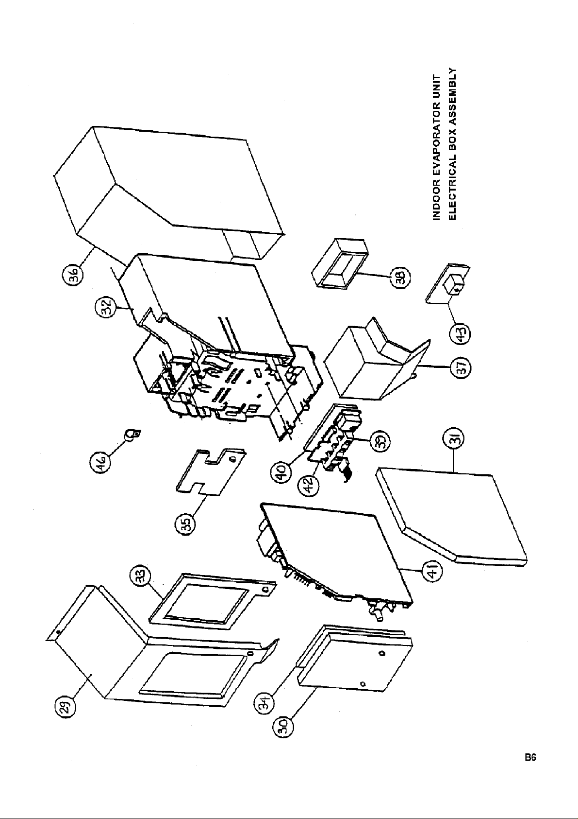
INDOOR EVAPORATOR UNIT
(R407C)
24 Filter 35-16-00010-001 2 2 2 2
NI 3M Purifying Filter 35-03-01460-001 1 1 1 1
NI Charcoal Purifying Filter 35-03-00260-001 1 1 1 1
25 Lens, Sensor 36-08-00250-001 1 1 1 1
26 Cover, Screw 36-08-00260-001 3 3 3 3
27 Label, LED Lens 36-08-00270-001 1 1 1 1
28 Evaporator Coil Asm. 37-16-08540-001 1 1 1 1
(include flare fittings, top, bottom &
back coil Asm., connecting
tubes)
29 Metal Cover, Electical Box 36-08-00280-001 1 1 1 1
30 Metal Cover, Terminal Connection 36-08-00290-001 1 1 1 1
31 Base, Main PCB 36-08-00300-001 1 1 1 1
32 Electrical Box 36-08-00310-001 1 1 1 1
33 Cover, Electical Box 36-08-00320-001 1 1 1 1
34 Cover, Terminal Connection 36-08-00330-001 1 1 1 1
35 Strain Relief, Interconnect 36-08-00340-001 1 1 1 1
36 Metal Electrical Box Asm 36-08-00350-001 1 1 1 1
37 Electrical Box, Front 36-08-00360-001 1 1 1 1
38 Holder, Receiver 36-08-00370-001 1 1 1 1
NI Mount Plate, Terminal Block 35-16-00030-001 1 1 1 1
NI Terminal Block ,9P 35-03-00540-031 1 1 1 1
39 Cover, LED 36-08-00380-001 1 1 1 1
40 Base, LED 36-08-00390-001 1 1 1 1
B3

EEEE1H1HFFFFEEEE444411228844NNN
N
Item6666
No.
Description
Service Part #
DDD
D
MODEL NUMBER
-----ELECTRICAL ASSEMBLY(Cont')-----
-----PACKAGING PARTS-----
FEDDERS
LARGE SPLIT
INDOOR EVAPORATOR UNIT
(R407C)
41 Main P.C. Board (C/O) 35-16-04160-012 1 -- 1 --
41 Main P.C. Board Kit (H/P) 50-18-0015N-001 -- 1 -- 1
(Includes LED, Receiver PCB,
All Thermisters, Cables)
42 LED PC Board 35-16-04110-011 1 1 1 1
43 Receiver PC Board 35-16-04120-011 1 1 1 1
44 Wiring Diagram (C/O) 36-08-00420-001 1 -- 1 -44 Wiring Diagram (H/P) 36-08-00430-001 -- 1 -- 1
NI Power Cord 36-08-00440-001 1 1 1 1
46 Strain Relief, Power Cord 36-08-00450-001 1 1 1 1
NI Clip, Thermistor 35-03-01280-001 1 1 1 1
NI Spring, Thermistor 35-05-00200-001 1 1 1 1
NI Indoor Air Thermistor,10K 35-11-04140-03K 1 1 1 1
NI Indoor Coil Thermistor,10K 35-11-04110-03K 1 1 1 1
NI Outdoor Coil Thermistor, 10K 35-11-04120-03K -- 1 -- 1
NI Jumper, Outdoor Thermistor 35-16-04170-011 -- 1 -- 1
48 Mounting Bracket, Unit 36-08-00460-001 1 1 1 1
49 Remote Control (C/O),Neuter 11-23-03640-020 1 - 1 -
49 Remote Control (H/P),Neuter 11-23-03640-021 - 1 - 1
50 Remote Control Holder 35-02-00070-01V 1 1 1 1
51 Packaging Clam Shell 36-08-00400-001 2 2 2 2
52 Carton,Neuter 36-08-00410-001 1 1 1 1
54 Accessory Kit Carton 35-03-00320-001 1 1 1 1
NI Unit Plastic Bag 35-08-01140-001 1 1 1 1
57 Signal/Thermistor Wire 15M,OD 35-02-01170-02K - 1 - 1
NI User Manual 35-03-01350-001 1 1 1 1
NI Installation Manual 35-24-00130-001 1 1 1 1
B4

EEEE1H1HFFFFCCCC444411228844NNN
N
Item6666
No.
Description
Service Part #
GGGG-----CHASSIS ASSEMBLY-----
-----REFRIGERANT ASSEMBLY-----
MODEL NUMBER
FEDDERS
LARGE SPLIT UNIT
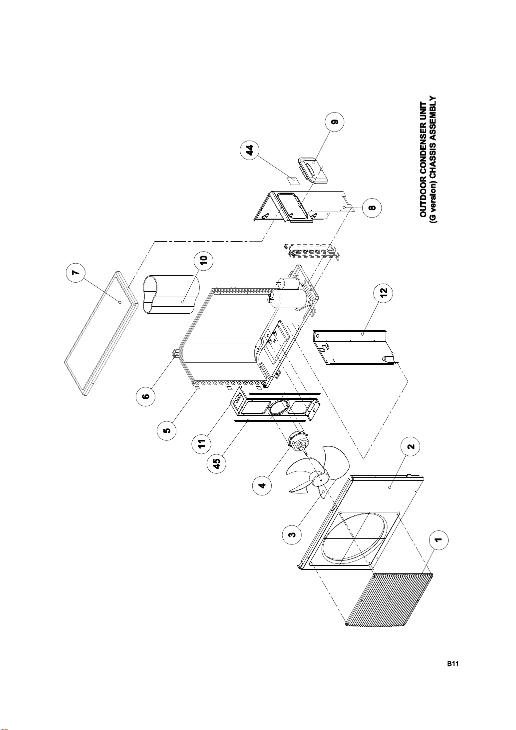
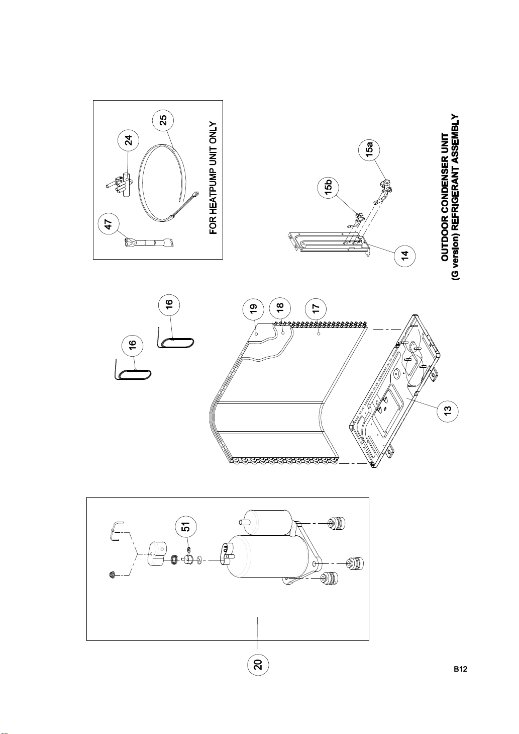
OUTDOOR CONDENSER UNIT
(R407C)
1 Front Grille 35-24-05150-001 1 1 1 1
2 Front Panel (painted),Neuter 35-24-05010-083 1 1 1 1
3 Fan Blade 37-24-01010-001 1 1 1 1
4 Fan Motor 35-24-90000-001 1 1 1 1
5 Mesh-Panel (securing) 35-08-02000-001 3 3 3 3
6 Rear Post (painted) 35-24-05050-081 1 1 1 1
7 Top Cover (painted) 35-24-05080-083 1 1 1 1
8 Side Panel (painted) 35-24-05060-081 1 1 1 1
9 Service Cover 35-24-05140-001 1 1 1 1
10 Compressor Blanket 35-05-00190-001 1 1 1 1
11 Motor Mounting Bracket (Painted) 35-24-05090-081 1 1 1 1
12 Partition (Asm with foam seal) 37-24-08130-001 1 1 1 1
44 Wiring Diagram (C/O) 35-24-00100-003 1 -- 1 -44 Wiring Diagram (H/P) 35-24-00120-003 -- 1 -- 1
45 Mounting Bracket Reinforced 37-24-05010-081 2 2 2 2
13 Base Pan Asm. (1-48 Frame) 35-24-08010-084 1 1 -- --
Base Pan Asm. (Bristol) 35-24-08010-081 -- -- 1 1
(include base pan and mounting
legs - painted)
14 Service Valve Plate (painted) 35-24-05100-083 1 1 1 1
15a 3-Way Service Valve, 5/8" 37-24-06010-003 1 1 1 1
15b 2-Way Service Valve, 3/8" 37-24-06020-002 1 1 1 1
B8
EEEE1H1HFFFFCCCC444411228844NNN
N
Item6666
No.
Description
Service Part #
GGG
G
MODEL NUMBER
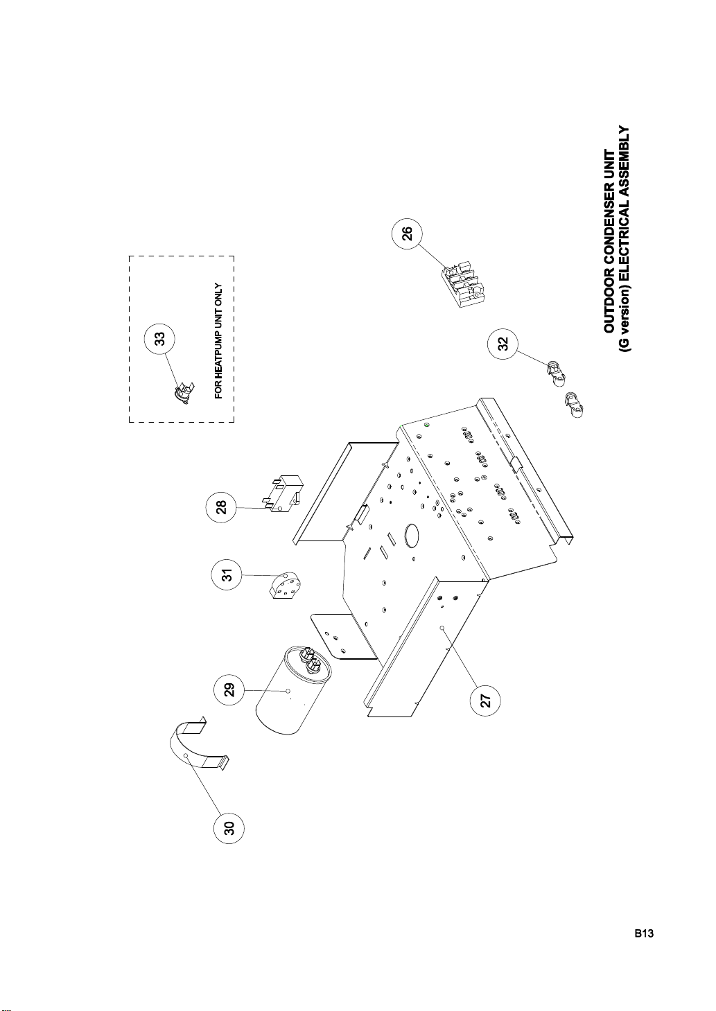
-----REFRIGERANT ASSEMBLY(Cont')-----
-----ELECTRICAL ASSEMBLY-----
FEDDERS
LARGE SPLIT UNIT
OUTDOOR CONDENSER UNIT
(R407C)
16 Capillary Tube, 0.064" ID x 13" S0-02-C0002-N14 1 1 1 1
17 Condenser Assembly, Inner (14FPI) 35-24-08020-002 1 1 1 1
18 Condenser Assembly, Outer (14FPI) 35-24-08030-002 1 1 1 1
19 Plastic Coil Protection Mesh 37-24-01020-001 1 1 1 1
20 Compressor Kit '( with accessories) 50-16-0114N-001 1 1 -- --
Compressor Kit '( with accessories) 50-16-0115N-001 -- -- 1 1
24 Reversing Valve 37-03-08190-001 -- 1 -- 1
25 Crankcase Heater 35-11-00340-009 -- 1 -- --
Crankcase Heater 35-11-00340-010 -- -- -- 1
47 Check Valve 36-08-00580-001 -- 1 -- 1
51 Overload Protect (DB35-00011C) 35-05-00620-001 1 1 - -
70 Filter-Drier 37-01-05010-001 1 - 1 70 Filter-Drier 37-24-06110-001 - 1 - 1
NI Strainer 88-60-00220-007 1 1 1 1
26 Terminal Block, 3 Pole 35-03-00570-001 1 -- 1 --
Terminal Block, 5 Pole 35-03-00580-001 -- 1 -- 1
27 Control Box 35-24-05040-001 1 1 1 1
28 Fan Motor Capacitor, 3uF 16-05-00750-002 1 1 1 1
29 Compressor Capacitor, 40uF/440V 16-05-00730-132 1 1 1 1
30 Strap, Capacitor 35-05-00240-001 1 1 1 1
31 Start Assist 16-06-03480-001 1 1 1 1
32 Strain Relief (Multi Usage Type) 35-03-25060-001 2 2 2 2
33 Thermostat-Bimetal 11-23-03950-001 -- 1 -- 1
B9
EEEE1H1HFFFFCCCC444411228844NNN
N
Item6666
No.
Description
Service Part #
GGG
G
MODEL NUMBER
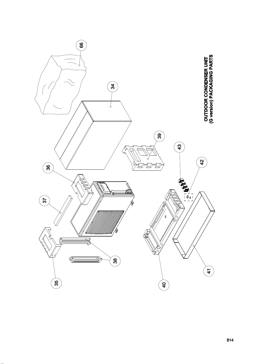
-----PACKAGING PARTS-----
FEDDERS
LARGE SPLIT UNIT
OUTDOOR CONDENSER UNIT
(R407C)
34 Carton,Neuter 35-24-00070-N01 1 1 1 1
35 EPS Pad, Top Left 35-24-00030-001 1 1 1 1
36 EPS Pad, Top Right 35-24-00040-001 1 1 1 1
37 EPS Tie-bar 35-08-02060-001 1 1 1 1
38 EPS Side Post 35-24-00020-001 2 2 2 2
39 EPS Side Pad 35-24-00050-001 1 1 1 1
40 EPS Bottom Pad 35-24-00060-002 1 1 1 1
41 Carton Box Base 35-24-00080-001 1 1 1 1
42 Drain Adapter Kit 35-08-00820-001 1 1 1 1
(include drain adapter, gasket)
43 Rubber Damper Feet 35-24-00010-001 4 4 4 4
66 Plastic Bag 35-08-00540-001 1 1 1 1
B10

SECTION C: INSTALLATION
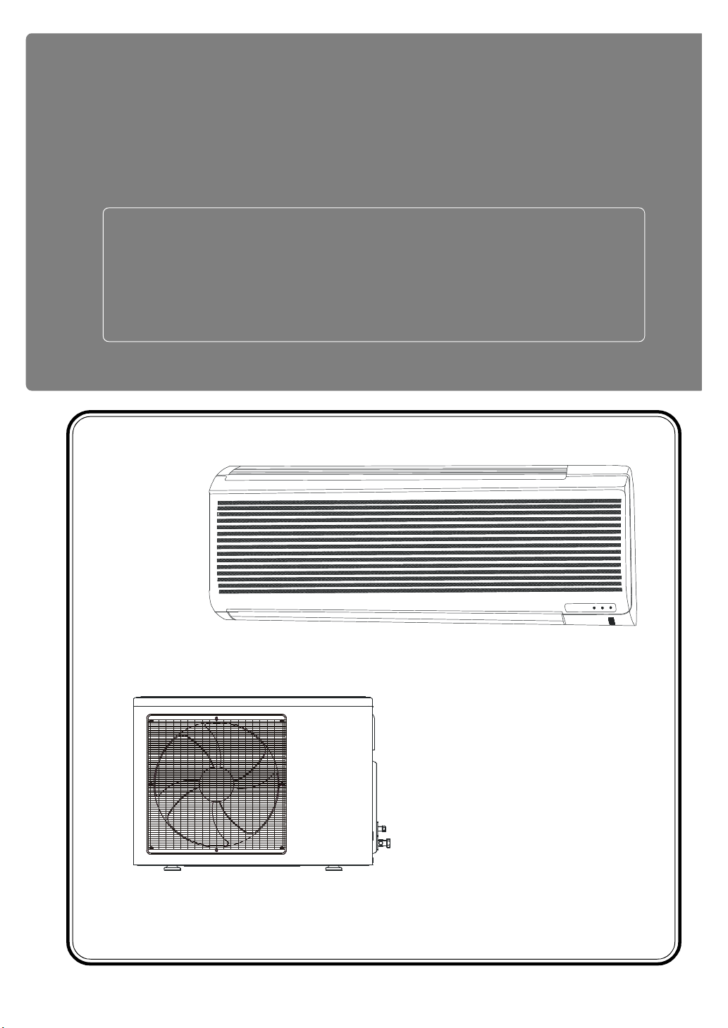
SPLIT TYPE AIR CONDITIONER
INSTALLATION MANUAL
®
For 18,000 - 24,000 Btu
C1

CONTENTS
SAFETY PRECAUTION ........................................................................... C3
PART LISTS ................................................................................................ C4
PREPARATION OF PIPING ................................................................... C5
Pipe Length, Elevation and refrigerant charge ....................... C5
Flaring of pipe ...................................................................................... C6
INDOOR UNIT INSTALLATION ............................................................ C7
Locating the indoor unit ................................................................... C7
Installing the wall bracket & drilling the piping hole. ............ C7
Routing the drain hose and tubing............................................... C8
Sealing The Drain Hose And Tubing ............................................ C9
Attaching The Unit To The Wall Bracket................................ C10
Wiring The Indoor Unit .................................................................. C10
Connecting The Piping To The Indoor Unit............................. C11
OUTDOOR UNIT INSTALLATION ..................................................... C12
Locating the outdoor unit............................................................. C12
Installing The Outdoor Unit.......................................................... C13
Connecting The Wires To The Outdoor Unit ......................... C14
VACUUMING THE PIPING & THE INDOOR UNIT ...................... C15
Removing air from the tubing and indoor unit ..................... C15
Restraining the piping ................................................................... C16
TEST RUN & CHECK ............................................................................ C17
Switch On The Power Supply ...................................................... C17
NOTICE TO THE CONSUMER .......................................................... C18
C2
SAFETY PRECAUTION
• Please read the “Safety Precaution” carefully before installing the unit.
• Pay special attention to signs of “WARNING” and “CAUTION”. The “Warning”
section contains matters which, if not observed strictly, may cause death or
serious injury. The “Caution” section contains matters which may result in
serious consequences if not observed properly. Please follow all instructions
strictly to help ensure your safety.
WARNINGWARNING
• We recommend that you ask a qualified technician to install your air conditioner in accordance with this Installation Manual.
• Read this manual carefully before using your air conditioner.
• All wiring must conform to local and national electrical codes.
• To avoid possible electrical shock, you must ground your air conditioner.
• This air conditioner requires a separate power supply on a separate fused
circuit.
• If the supply cord is damaged, it must be replaced by a qualified technician.
• Do not disconnect or connect the power plug during operation.
• Do not insert your finger, a stick or any object into the air inlet and air
outlet.
CAUTIONCAUTION
• Keep this manual for future reference as it contains important installation and safety instructions.
• Do not install the outdoor condensing unit near flammable gas. The
condensing unit may catch fire if flammable gas leaks.
• Do not connect the power plug with wet hands.
• Do not expose your skin directly to the airflow for a long time.
C3

PART LISTS
A number of small parts have been packed with the indoor unit. Please check the
contents of the box with the list below.
Description Quantity
Wall Bracket
Indoor To Outdoor Signal
Connecting Wire (For Heat-
pump Model Only)
Remote Control
AAA batteries
Screws for
Remote Control Holder
Remote Control Holder
1
1
1
2
2
1
Screws for
Wall Mounting Bracket
Base Leg Damper
Drain Adapter
Drain Gasket
6
4
1
1
C4

PREPARATION OF PIPING
Pipe Length, Elevation and refrigerant charge
• Each outdoor unit comes with a
refrigerant charge that is sufficient for
use with interconnecting tubing up to
7.5 metres.
• If the required interconnecting tube
exceeds 5 metres, for each additional
metre, add the amount of refrigerant
according to the table as shown below.
Max. Elevation
per Indoor Unit
Max. Piping
Length per
Indoor Unit
Liquid Pipe
Size
1/4”
3/8”
• The recommended maximum allowable
tubing length between indoor and
outdoor is 15 metres.
• The recommended maximum allowable
elevation between indoor and outdoor is
5 metres.
Additional
Refrigerant
21 g/m
57 g/m
Cutting The Pipe And The Cables.
• Measure the distance between the
indoor and the outdoor units.
• Cut the pipe length about 10% more
than the measured distance.
• Cut the electrical cable with about 2
metres more than the measured distance.
C5

Removing burrs
• Remove burrs from the cut edges of
the pipes.
• Turn the pipe end down to avoid the
metal powder entering the pipe.
CAUTION :CAUTION :
If burrs are not removed, they mayIf burrs are not removed, they may
cause a gas leakage when incause a gas leakage when in
operation.operation.
Flaring of pipe
• Insert the flare nut or coupling nut over
the tubing with the threaded end facing
the end of the tubing.
PREPARATION OF PIPING
• Clamp the tube in the flaring block,
adjust the tube so that it is slightly
above the block (about 1/3 of the total
height of the flare).
• Place the yoke on the block with the
taper cone over the end of the tube.
• Turn the handle until the flare is
completed.
• Check for proper flaring of the tube. A
properly flared tube should be of even
thickness and evenly shine.
Tubing
CAUTION :CAUTION :
Any bend in the tubing must have a minimum radius of 100mm toAny bend in the tubing must have a minimum radius of 100mm to
prevent leakage.prevent leakage.
Do not bend any section of the tube repeatedly.Do not bend any section of the tube repeatedly.
Do not remove the flare nut from the tubing in the indoor unit until youDo not remove the flare nut from the tubing in the indoor unit until you
are ready to connect it to the outdoor unit.are ready to connect it to the outdoor unit.
C6

Locating the indoor unit
INDOOR UNIT INSTALLATION
• Do not install the unit near any heat
source, steam source or flammable gas
source.
At least 40mm
• Locate the unit in a place where it will
provide cool air throughout the room.
• Make sure the minimum distances from
Wall
At least
50mm
the walls and obstructions are maintained as shown on the right.
• Ensure that the unit’s airflow is not
obstructed.
• Place the unit so that the air filter can
be removed easily and maintenance
work can be carried out without obstructions.
Installing the wall bracket & drilling the piping hole.
• Mount the wall bracket in a level angle.
• Secure the bracket directly on the wall.
• If you are mounting the bracket on
plaster board, use the tapping screws
provided to secure the bracket on to the
wall.
• If you are mounting the bracket on a
concrete wall, use anchor bolts to
secure the bracket to the wall.
45mm
∅65mm
Ceiling
At least
50mm
Wall
2300-3000mm
Floor
650mm
780mm
• If you are using the Right or Left back
outlet, see page 8, drill a 65mm diameter piping hole at either on the right or
the left, and the hole should be slightly
slanted to the outdoor side.
• Cut the wall tube (not provided) to fit the
wall thickness.
• Connect the wall cap (not provided) to
the wall tube with polyethylene tape and
insert the tube in the wall.
Polyethylene tape
Wall cap
Wall tube
Inside
6-10mm
Wall
Outside
C7

INDOOR UNIT INSTALLATION
Removing The Decorative Front
• Remove the Decorative Front by
removing 3 screws.
• Remove it by lifting it up and then
out.
Routing the drain hose and tubing
• The following illustrate the different piping outlet option.
Right Back Outlet
If you are using the following outlet option, you must wire the indoor unit before
attaching it to the wall bracket.
Right Outlet Left Outlet
Bottom Outlet
Left Back Outlet
CAUTION :CAUTION :
Do not remove the flare nut from the tubing in the indoor unit until youDo not remove the flare nut from the tubing in the indoor unit until you
are ready to connect it to the outdoor unit.are ready to connect it to the outdoor unit.
Bend tubes with caution.Bend tubes with caution.
C8

Sealing The Drain Hose And Tubing
• Wrap the drain hose, tubing and electric wire together with polyethylene
tape.
• Wrap all exposed tubing with tape
except tubing, which will rest inside the
unit.
INDOOR UNIT INSTALLATION
Use caution
Drain hose
when bending
• Insert the tubing, hose and wire
through the wall tube with the drain
hose in the lowest position.
• Make sure the tubing, hose and wire
angle downwards as they pass through
and exit the wall tube.
Polyethylene tape
Piping Tape
Connecting Wire
Gas Pipe
Insulations
Tubing
Liquid Pipe
Drain Pipe
C9

INDOOR UNIT INSTALLATION
Attaching The Unit To The Wall Bracket
If you are using right, left or bottom piping outlet (see page 8) you must wire the
unit before you attach it to the wall bracket.
• Hook the unit to the hangers on top
of the bracket first and then press
the lower left and right side of the
unit against the wall bracket until it is
seated properly.
• Ensure that the unit is level.
• Ensure that the drain hose is in the
proper position.
Drain
Hose
Wiring The Indoor Unit
You may connect the wires to the indoor unit by opening the Decorative Front
Grille.
• Remove 2 screws that secure the Control Box Cover.
• Connect the wire as shown on the wire diagram located on the control box
cover or refer to the Wiring Diagram Section in this manual.
Decorative
Front Grille
Control Box
Cover
Wire Diagram
Screws
• Route the interconnecting wires to the
back through the opening in the front as
shown.
• Ensure all terminals are securely
tightened.
(Top View)
Route the wires through
this opening towards
the back of the unit.
C10

INDOOR UNIT INSTALLATION
Connecting The Piping To The Indoor Unit
• Align the center of the piping
and then sufficiently tighten the
flare nut with fingers, tighten
the flare nut with torque wrench
according to the table as shown
below.
Pipe Size
Torque (N.m)
Diameter
9.52mm (3/8”)
15.87mm (5/8”) 58.7 - 73.2
Torque Table
35.6 - 44.4
Indoor unit tubing
Flare nut
Torque
wrench
Spanner
C11

Locating the outdoor unit
• Locate the outdoor unit where the air
flow around it is not obstructed.
OUTDOOR UNIT INSTALLATION
• Ensure that the base is level and does
not exceed the maximum slope of 5
degrees.
• Secure the unit to a base with anchor
bolts to reduce vibrations and noise.
• Place the unit with access space for
servicing and maintenance.
• Do not install the unit near a heat
source, steam source and flammable
gas.
• Ensure that the minimum distances
around the unit are maintained as
shown on the right.
• For Heatpump unit, mount the unit
above the snow line, if possible.
At
least
40cm
At least
60cm
At
least
60cm
At least
10cm
At least
60cm
C12

Installing The Outdoor Unit
OUTDOOR UNIT INSTALLATION
• Attach the Base Leg Damper by
sliding the slot into the base of the
outdoor unit.
• Attach the drain gasket and drain
adapter to the base pan of the unit
before you secure the unit.
• Fasten the unit down, referred to
the mounting dimensions as
shown here.
Base Leg Damper
Drain Adapter
604mm
356mm
Connecting The Pipe To The Outdoor Unit
• Align the center of the piping and
sufficiently tighten the flare nut with
fingers.
• Finally, tighten the flare nut with torque
wrench according to the Table shown
here.
Pipe Size
Diameter
9.52mm (3/8”)
15.87mm (5/8”) 58.7 - 73.2
Torque Table
Torque (N.m)
35.6 - 44.4
Liquid
Line
Gas
Line
Torque
Wrench
C13

OUTDOOR UNIT INSTALLATION
Connecting The Wires To The Outdoor Unit
• Remove the Service Cover from the
unit.
• Connect the wires to the terminals
according to the wiring diagram shown
in the wiring diagram section or at the
back of the Service Cover.
• Clamp the wire to the unit with the wire
retainer.
• Form a drip loop in the wire to prevent
water from entering the unit along the
cord.
Screw
Service Cover
Wires
CautionCaution
This air conditioner must beThis air conditioner must be
disconnected from the supply by adisconnected from the supply by a
switch having a 3mm contactswitch having a 3mm contact
separation in all poles.separation in all poles.
For Heat-Pump model : Route theFor Heat-Pump model : Route the
Outdoor Coil Thermister WiresOutdoor Coil Thermister Wires
separately from high voltageseparately from high voltage
interconnecting cables.interconnecting cables.
• The same Wire Retainer can be used on two types of wires by changing the
orientation as shown below.
Wire Retainer
Drip Loop
For Flat Type
Connecting Wire
For Round Type
C14

VACUUMING THE PIPING & THE INDOOR UNIT
Checking for gas leakage
• Connect the Manifold gauge to the
outdoor unit gas line port as shown
on the right.
• Connect the charging cylinder to the
Manifold gauge and open the valve of
the Cylinder.
• Open the low pressure valve of the
Manifold gauge until the meter reads
steady at about 150-200 psig.
• Check for gas leakage especially
around the tubing connectors with a
gas-leak detector.
• If leakage was found, retighten the connector with Torque wrench and repeat
the gas leakage check again.
• Upon completion of the leak test, close the valve of the charging cylinder and
low side valve of the manifold gauge. Remove charging cylinder. Recover
refrigerant from indoor unit and piping through the manifold gauge.
Manifold gauge
Charging
Cylinder
Removing air from the tubing and indoor unit
It is necessary to remove all air from the Refrigeration Cycle, as this air contains moisture, which may cause a malfunction or ineffectiveness of the compressor.
• Connect the center hose of the
Manifold gauge to the vacuum
pump.
3-way
valve
• Connect the Manifold gauge to the
outdoor unit gas line port as shown.
• Turn the vacuum pump on for about
10-15 minutes in order to evacuate
the air.
• Close the manifold valve, then turn
off the vacuum pump and disconnect
the hose.
Vacuum
pump
3-way
valve
Manifold gauge
C15

VACUUMING THE PIPING & THE INDOOR UNIT
• Unscrew the cap on the 2-way
and 3-way valve.
• After all lines are installed and
leak tested, set both the liquid
and gas line valves to fully open
position with the Allen Key for
the unit operation, as shown.
• Reinstall the cap and torque to
the specified value under Torque
Table on page 10.
Restraining the piping
• Wrap the tubing connection to
the unit with the insulation and
seal it with polyethylene tape.
Using Allen
Key to open
fully for unit
operation
Allen Key
Cap
• You may connect an additional
drain hose. The end of the drain
outlet should keep a distance
from the ground.
• Tape the connecting piping,
drain hose and wires with
polyethylene tape from bottom
upwards to the top, and secure
them to the wall.
• Fill any gap in the wall that has
been core drilled.
• Form a drip loop on the electrical cable to prevent water
entering the electrical compartment.
Drain
Loop
Clamp
Drain
Hose
C16

TEST RUN & CHECK
Switch On The Power Supply
CAUTION :CAUTION :
Ensure that all the piping and wiring are connected properly andEnsure that all the piping and wiring are connected properly and
securely, before turning the power On.securely, before turning the power On.
• Turn the main switch of the unit to
On.
• Operate the Indoor unit at Cooling/Heating mode for fifteen
minutes or more.
• Measure the temperature of the
intake and the discharge air, the
temperature difference should be
o
at least 9
C.
C17

NOTICE TO THE CONSUMER
Checking The Unit
• Check all the control functions.
• Check all the indicator lights.
• Check that the drain hose is draining properly.
• Ensure all the units are fastened properly and free from vibrations.
Upon completion of installing and checking the unit:
• Supply the consumer with the Operating Manual.
• Demonstrate the functions of the remote control.
• Demonstrate how to remove and clean the air filters.
• Explain the 3 minute delay function.
C18

SECTION D: TROUBLE SHOOTING

D1

D2
SYMPTOM DIAGNOSIS REMEDY
Both fan & compressor not running. Fuse open or breaker tripped. Inspect and repair.
Poor power plug connection. Inspect.
Power failure. Inspect.
Control circuit malfuction. Replace parts.
Compressor does not run. Compressor motor windings open. Replace compressor.
Compressor locked. Replace compressor.
Defective overload. Replace part.
Defective capacitor. Replace part.
Control circuit malfuction. Replace part.
Voltage drop at start. Check supply wiring.
Pressure unequal at start. Restart in 10 minutes. Inspect Control Circuit.
Fan does not run. Fan motor windings open. Replace part.
Defective capacitor. Replace part.
Control circuit malfunction. Replace part.
Defective bearing. Replace part.
Fan blade interference. Inspect.
Unit operates but does not cool. Refrigerant circuit oil leak. Leak repair and replenish gas.
Small or no sound of refrigerant flow. leak repair and replenish gas, or
Low system temperature / pressure. defective compressor. Replace part.
Small or no sound of refrigerant flow. System restriction; replace capillary tube
High rise in temperature / pressure of and strainer.
condenser (frost forms on evaporator).
Poor cooling. Incorrect thermostat setting. Adjust.
Open door or window. Correct.
Air inlet or outlet obstructed. Correct.
Unit exposed to sun. Draw curtains.
Additional heat sources or occupants. Recalculate cooling load.
Poor installation location. Consider relocation.
Incorrect cooling load calculation. Recalculate cooling load, resize.
Dirty filter. Clean filter.
Overcooling. Incorrect cooling load calculation. Adjust fan speed and thermostat setting.
Recalculate cooling load, resize.
High level of noise and vibration. Compressor noise or vibration. Check compressor mounting & isolation.
Tubing noise and vibration. Redress tubing.
Fan motor noise or vibration. Check fan motor mounting.
Check for broken fan blade.
Radio noise and interference. Defective electrical contact. Repair.
Water leaks. Drain pipe blocked. Inspect and repair.
Drain pipe blocked. Inspect and repair.
Improper installation. Inspect and repair.

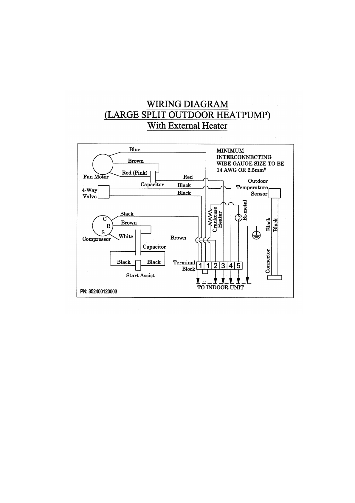
SECTION E: WIRING DIAGRAM

E1

E2

E3
E4

SECTION F: TECHNICAL DATA

REMOTE CONTROL AND PC BOARD FUNCTIONAL SPECIFICATIONS
LARGE SPLIT UNIT (18 / 24K)
The electronic air-con control system consists of :
I. CONTROL SYSTEM
1) Hand-held Infra-Red transmitter with Liquid Crystal Display panel (hand held unit)
2) Receiver module consisting of:
a) Main receiver Board
b) LED Board
c) Sensor Board
3) The devices that are controlled by this electronic control system are :
a) Outdoor Compressor
b) Outdoor Fan
c) Outdoor 4 way Valve (applicable for Heat Pump Unit only)
d) Indoor Fan, single phase induction, tri- speed
e) Stepper motor
4) Features of this electronic controller include:
a) Operating voltage of 220/240Vac ±10%, 50/60Hz.
b) Step-down transformer that complies with IEC standard specifying High-Pot. test at
1500V.
c) 50 mm x 43 mm Liquid Crystal Display on the hand-held transmitter.
d) Computer Operating Properly (COP) watchdog timer feature for graceful software
reset after any un-recoverable fault.
e) Room temperature control range of 16°C to 31°C.
f) 3-minute compressor switch on delay except on power-up or system reset for
compressor protection.
g) 60-second four-way valve switch over (meaning switch from ON to OFF and vice-
versa) delay after turning off the compressor except on power-up or system reset
(applicable on Heat Pump Unit only).
h) Cool fan prevention measure in heat mode to reduce discomfort to user caused by
circulation of cold air by the indoor fan (applicable on Heat Pump Unit only).
i) Indoor coil overheat protection in heat mode (applicable on Heat Pump Unit only).
j) Indoor coil protection against icing in cool mode (applicable on Heat Pump Unit
only).
k) Outdoor coil protection against icing in heat mode (applicable on Heat Pump Unit
only).
l) Filter dirty LED indication after every 500 hours of operation.
m) On/Off switching hysteresis to prevent frequent switching and to extend live of the
relays.
n) Self-test function for quick production test, system diagnosis and system integrity
checks.
o) Thermistor fault indication.
p) Gas Leaks Protection.
r) Outdoor Coil Overheat Protection in Cool Mode (applicable on Heat Pump Unit
only).
F1

II. Hand-held Transmitter
Operating Voltage : 3.0 Vdc.
Power Source : 2 "AAA" size batteries
Battery Life Expectancy : more than 1 year
Range of Transmission : at least 8m from the infrared sensor of the receiver module
Angle of Transmission : 45° about normal
Medium of Transmission : infrared transmission
The hand-held transmitter has an iconic LCD panel that displays the following information:
i) Iconic representation of current mode of operation
ii) Value of set/desired room temperature
iii) Iconic representation of current indoor fan speed
iv) Iconic representation of current vane position
v) Vane swing icon, appears if vane swing function has been activated.
vi) 12-hour format display of time of the day
vii) On/off timer settings, if timer function has been activated
viii) Sleep function icon, if sleep function has been activated
ix) Arrow icon to indicate the sequence of ON/OFF timer actions
x) “Signal transmitted” icon to indicate that transmission of command code to
receiver is being done.
The hand-held transmitter has one button for each of the following functions in manual
operation:
a) POWER ON/OFF button Toggles the air-con ON and OFF
b) ∧∧, the “Temperature Increases the set temperature
Increment” button
c) ∨∨, the “Temperature Decreases the set temperature
Decrement” button
d) MODE button Toggles the mode of operation between AUTO,
COOL, DRY, FAN and HEAT (Heat Mode only
applicable on Heat Pump Unit).
e) FAN button Toggles the fan speed between LOW, MEDIUM, HIGH
and AUTO.
f) SWING button Causes the vane to be moved up and down continuously.
g) VANE button Toggles vane position between ANGLE, DOWN,
MIDDLE and AUTO.
F2

h) CLOCK button Starts and stops the setting of time of the day.
Deactivates timer function.
The accuracy of the time setting must be + / - 15 second
per day.
i) SLEEP button Activates / deactivates sleep function
j) START button Activate / deactivate ON timer
k) STOP button Activates / deactivates OFF timer
l) HR. button Adjusts the hour setting of the time of the day if the
CLOCK button has been pressed prior to this step. Adjust
the hour setting of the ON/OFF timer if the Start/Stop
button has been pressed.
m) MIN. button Adjusts the minute setting of the time of the day if the
CLOCK button has been pressed prior to this step. Adjust
the minute setting of the ON/OFF timer if the Start/Stop
button has been pressed.
(a) to (d) and (i) are exposed buttons. The remaining buttons are concealed behind a hinged
door.
A "beep" sound, acknowledging the reception of a valid infrared signal will be generated by
the main receiver board if a valid button is pressed.
III. Receiver Module
Input Voltage: 220/240 Vac ±10%, 50/60Hz.
Power Relay Contact Ratings: 240Vac/30A, for compressor.
240Vac/5A, for indoor fan motor, outdoor fan motor
and 4-way valve.
1. Main Receiver Board
Main board, where the dual in-line package (SDIP) microcontroller is mounted.
It also holds a push button switch called Operation/Filter Reset Button. Main receiver board
material must be PR4 Grade.
F3

1.1. Operation / Filter Reset Button.
Operation
By pushing this button, one of the following two air-con operations are selected.
a) AUTOMATIC operation Selecting this operation is equivalent to selecting Auto mode,
auto fan speed control and auto vane function in manual
operation. The set temperature is internally fixed at 22°C and
cannot be changed.
This operation is useful when the hand held transmitter is lost
or faulty.
b) OFF operation The air-con will be switched off. The hand-held transmitter will
not be able to control the operation of the Air-con.
Note that the ac. power supply is still connected to the receiver module of the electronic
controller although the air-con is switched off.
This reset button selection is cyclic between AUTOMATIC – OFF.
Filter Reset
Whenever the Air-con is switched on, the air filter usage time will be monitored by the
microcontroller. When the period of usage reaches 500 hours, the red LED on the LED board
will light up to indicate that the air filter is dirty. The filter should then be removed and
cleansed.
To extinguish the red LED after cleansing and replacing the filter, press and hold the
Operation / Filter reset switch for 3 seconds. A beep sound will be heard after 3 seconds to
indicate that the red LED has been extinguish.
1.2. RFI Filter
This is built into the main receiver board to remove RFI from the AC power supply. RFI filter
could be removed provided that the EMC test result was satisfactory.
2. LED Board
Three LEDs on the board provide the following indications :
a) Power on/Defrost (green) LED Lights up when power on.
It blinks at approximately 60 times per minute
during de-icing.
b) Timer activated (yellow) LED Lights up upon activation of either one or both
of the START/STOP timers.
F4

c) Filter dirty/System Fault (red) Lights up after 500 hours of operation, to
LED indicate that the filter requires cleansing.
The Operation/Filter reset switch should be
pressed by the user to switch this LED
indication off after cleansing and replacing the
filter.
When Indoor air thermistor (TH1) fault. It blinks at
approximately 30 times per minute, only indoor fan is
operating and reset by turning off main power supply.
When Indoor Coil thermistor (TH2) fault. It blinks at
approximately 60 times per minute. The indoor fan is
operating according to the cold air prevention in heat
mode and normal in cool mode and reset by turning off
main power supply.
When outdoor coil thermistor (TH3) fault. It blinks at
approximately 150 times per minute. The indoor fan is
operating according to the cold air prevention in heat
mode and normal in cool mode and reset by turning off
main power supply. In case the thermistor is fault, the
transimitter will not be able to function (applicable on
Heat Pump Unit only).
Check thermistor open or short circuit.
3. Infra Red Sensor Board
An Infra-Red sensor on this board detects infra-fed signal transmission from the remote hand
held transmitter.
IV. Operations of the electronic controller
1. ON
In manual operation, the air-con is switched on when ON/OFF button of the hand held
transmitter is pressed while the air-con is off.
For automatic operation, the air-con is switched on if the push botton is pressed once.
The microprocessor will regulate room temperature automatically.
2. OFF
In manual operation, the air-con is switched off once the ON/OFF button is pressed
again or when the operation push button is pressed two times.
When the air-con is turned off, it does not regulate the indoor temperature.
The vane motor will execute a final sequence of movement to the HOME position,
causing the air flow outlet to be fully closed.
F5

3. 3-min. compressor switch on delay
The compressor is not switched on again immediately after being switched off. The
air-con controller waits for 3 minutes before turning it on again to protect it.
This protective measure applies throughout the operation of the air-con except on
power-up.
4. 60-second 4-way valve delay (applicable on Heat Pump Unit only)
This refers to the 60-second delay after turning off
compressor before the 4-way valve is switched over from off to on or vice-versa.
This delay allows the safe, gradual transition of the air-con operation from a cooling
function to heating function or vice versa.
5. Cool fan prevention in heat mode (applicable on Heat Pump Unit only)
When compressor starts in heating operation or after defrosting, the indoor fan
changes the speed due to the indoor coil thermistor temperature and operation time to
blow out warm air.The indoor fan runs according to the following table during heat
mode:
STEP 1:
ID Coil Temp., T
T<=28°C 28°C<T<30°C T>=30°C
ID Fan STOP * LOW
STEP 2:
ID Coil Temp., T
T<=33°C 33°C<T<36°C T>=36°C
ID Fan LOW * SET
STEP 3:
ID Coil Temp., T
T<=46°C 46°C<T<50°C T>=50°C
ID Fan SET * HIGH
* Maintain current state
The start-up warm airflow control program is regardless room temperature. The
indoor fan is also not switched on while the outdoor coil is being de-iced for the same
reason.
6. Indoor coil icing prevention in cool mode
Should the indoor coil temperature dip to 2°C or lower in cool mode for at least 2
mins, de-icing will be executed to remove the ice formed at the indoor coil. De-icing
will be stopped when the indoor coil temperature rises to 10°C or higher or 10 mins
lapse.
7. Outdoor coil icing prevention in heat mode (applicable on Heat Pump Unit only)
If the outdoor coil temperature dips to below -4°C in heat mode. It will perform Deice according to a specified algorithm, and de-ice the outdoor coil if necessary.
F6

V. Modes of Operation
1. Cool Mode
The air-con controller lowers the room temperature in this mode.
In cool mode, the indoor fan is always turned on, allowing it to run at the set speed.
To stop the cool mode cycle, the compressor, outdoor fan are turned off, the 4-way valve
which serves no function in this mode is still kept at off. The indoor fan is however allowed
to continue running at set speed.
The controller monitors room temperature and compares it against set/desired temperature. It
starts and stops the cool mode cycle according to the following rules:
Room Temperature
Cool Mode Cycle
* Maintain current state
If room temperature ≤ 16°C, compressor, outdoor fan and 4-way valve turn off. The indoor
fan runs according to following table:
ID Room Temp., Tr
ID Fan LOW * SET
* Maintain current state
2. Dry Mode
Dry mode operation extracts moisture from the indoor air and tries to maintain room
temperature to the default set temperature of 22°C.
To dry the air, the controller executes the dry mode cycle, which toggles the compressor and
outdoor fan on for 10 minutes and off for 5 minutes repetitively.
The temperature setting, which is not changeable by user, is internally set at 22°C.
In this mode, the indoor fan constantly runs at the low speed. The 4-way valve that serves no
function in this mode is always kept OFF.
Room Temperature
Dry Mode Cycle
Pre-dry : compressor on, outdoor fan on and 4-way valve kept off.
* Maintain current state
3. Heat Mode (applicable on Heat Pump Unit only)
Heat mode operation can be chosen if it is desired to raise the room temperature. In this
mode, the air-con controller turns on the compressor, outdoor fan, 4-way valve and indoor
fan to provide the heating effect. The above operation, when executed in accordance to the
device protection criteria and cool fan prevention requirement is termed the heat mode
cycle.To stop heat mode cycle, the compressor and outdoor fan are turned off.
< Set pt-1°C = Set pt-1°C = Set pt. = Set pt+1°C > Set pt+1°C
Stop Stop * Start Start
Tr<=15°C 15°C<Tr<16°C Tr>=16°C
<Set pt-1°C Set pt-1 °C Set pt. Set pt+1°C >Set pt+1°C
Start Start * Pre-dry Pre-dry
F7

If the room temperature >=31°C, compressor off, outdoor fan off and 4-way valve remains
on, indoor fan runs according to following table:
ID Room Temp., Tr
Tr<=31°C 31°C<Tr<32°C Tr>=32°C
ID Fan SET * LOW
* Maintain current state
The heating cycle starts and stops according to the result of set temperature - room
temperature comparison:
ID Room Temp.
Heat Mode Cycle
< Set pt-1°C = Set pt-1°C = Set pt. =Set pt+1°C > Set pt+1°C
Start Start * Stop Stop
* Maintain current state
The 4-way valve will always be on in this mode except during de-icing, while the indoor fan
will be turned on or off in accordance to cool air prevention requirement.
4. Auto Mode
Depending on the room temperature, the air-con controller will automatically select cool, dry
or heat mode when this mode is first selected. The selected mode of operation will not be
exited until Auto mode is de-selected. If automatic operation is chosen, auto mode will be
automatically selected.
Room Temperature Range Mode of Operation That Will Be Entered if Auto Mode
Is Selected
Room Temp. >24ºC Cool Mode
19 ºC < Room Temp. ≤ 24ºC
Room Temp. ≤ 19ºC
Heat Mode (Heat Pump Unit only)
Dry Mode
Mode selection rule in Auto mode
The set temperature is internally set at 22ºC. In manual operation, the user can change it in
steps of 2ºC to 20ºC or 24ºC by pressing "∨∨" or "∧∧" button on the hand-held transmitter.
Conversely, this is not possible in automatic operation.
5. Fan Mode
Only indoor fan and the vane operate in this mode.
The user can select the desired indoor fan speed and vane position, but auto fan speed
selection is not available.
F8

VI. Temperature Control and Measurement
1. Temperature Measurement Accuracy
The temperature measurement range of the air-con controller is from -10ºC to 60ºC.
Measurement accuracy is given in the following Table:
ºC + - ºC + - ºC + - ºC + - ºC + -
-10 1 1 5 1 1 20 1 1 35 1 1 50 1 1
-9 1 1 6 1 1 21 1 1 36 1 1 51 1 1
-8 1 1 7 1 1 22 1 1 37 1 1 52 1 1
-7 1 1 8 1 1 23 1 1 38 1 1 53 1 1
-6 1 1 9 1 1 24 1 1 39 1 1 54 1 1
-5 1 1 10 1 1 25 1 1 40 1 1 55 1 1
-4 1 1 11 1 1 26 1 1 41 1 1 56 1 1
-3 1 1 12 1 1 27 1 1 42 1 1 57 1 1
-2 1 1 13 1 1 28 1 1 43 1 1 58 1 1
-1 1 1 14 1 1 29 1 1 44 1 1 59 1 1
0 1 1 15 1 1 30 1 1 45 1 1 60 1 1
1 1 1 16 1 1 31 1 1 46 1 1
2 1 1 17 1 1 32 1 1 47 1 1
3 1 1 18 1 1 33 1 1 48 1 1
4 1 1 19 1 1 34 1 1 49 1 1
Temperature measurement error
2. Room Temperature Control Range
The room temperature control range of the air-con controller is from 16ºC to 31ºC, both
inclusive. In manual operation, set temperature is adjusted using the temperature setting
buttons "∧∧" and "∨∨" on the hand-held transmitter.
At each press of one of the buttons, the set temperature is changed by 1ºC if it is currently in
cool or heat mode until the upper limit of 31°C or the lower limit of 16°C is reached. In Auto
mode, pressing the temperature setting buttons will cause the set temperature to change in
steps of 2°C until the upper limit of 24°C or the lower limit of 20°C is hit, but the
temperature setting will not be displayed on the hand-held transmitter.
VII. Auto Fan Function
Auto fan function is not available in dry and fan modes.
This function will be disabled if the sleep function is later selected. On the other hand, if
sleep function is activated first, it is not possible to select the Auto fan function.
In automatic operation, the Auto fan function will be chosen if the air-con operates in cool or
heat mode.
F9

When the indoor fan control is set to Auto, the fan speed is automatically selected according
to the mode of operation, set temperature and room temperature.
In cool mode, choosing Auto Fan will result in the following automatic fan speed selection:
Room Temperature
Indoor Fan Speed
< Set pt-3°C = Set pt-3°C = Set pt. = Set pt+3°C > Set pt+3°C
LOW LOW * HIGH HIGH
* Maintain current fan speed
Therefore, if the temperature set point is 20°C when cool mode is first entered in a room at
23°C, the indoor fan speed will be automatically HIGH.
The Indoor Fan Speed still remains at HIGH when the room temperature later lowers to 20°C.
When the room temperature falls further to 17°C, indoor fan speed changes to LOW.
If the room temperature rises to 20°C again, the indoor fan will still run at LOW speed.
Indoor fan speed will not be changed to HIGH unless the room temperature rises further to
23°C.
In dry mode, the indoor fan constantly runs at low speed. The Auto Fan function is not
available:
Room Temperature
Indoor Fan Speed
< Set pt-1°C = Set pt-1°C = Set pt. = Set pt+1°C > Set pt+1°C
LOW LOW LOW LOW LOW
In heat mode (Heat Pump Unit only), indoor fan speed is controlled as follows:
Room Temperature
Indoor Fan Speed
< Set pt-3°C = Set pt-3°C = Set pt. = Set pt+3°C > Set pt+3°C
HIGH HIGH * LOW LOW
* Maintain current fan speed
For example, if the set temperature is 20°C when heat mode is entered in a room at 17°C, the
indoor fan speed will be automatically HIGH.
The indoor fan speed still remains at HIGH when room temperature later rises to 20°C.
When the room temperature rises further to 23°C, the indoor fan speed is changed to LOW.
If the room temperature subsequently falls to 20°C again, the indoor fan will still run at LOW
speed. The indoor fan speed will not be changed to HIGH unless the room temperature dips
further to 17°C.
When Sleep function is selected in manual operation, indoor fan speed will be fixed at LOW
until the air-con is eventually turned off by sleep function.
F10

VIII. Vane Function
1. Vane Position
HOME The vane will be at this position whenever the air-con is off. Its exact
angle is 115° counter-clockwise from position 3.
POSITION 1 The vane plane is positioned 70° counter-clockwise from position 3. cool,
dry and fan modes default vane position.
POSITION 2 The vane plane is 50° counter-clockwise from position 3.
POSITION 3 The vane plane is vertical (Heat mode default vane position).
NB. For the vane position discussion, view the vane from the left side of the air-con indoor
unit.
2. Vane Control
When the Air-con is first switched ON in manual operation, the vane will move to the
position indicated on the hand-held transmitter.
When the Air-con is first powered up, or when the air-con is switched OFF either by toggling
the POWER ON/OFF button in manual operation or by pushing the operation/ filter reset
button to OFF position, the vane will be moved to HOME position so that the air flow outlet
is completely closed.
In manual operation, the vane can be set to position 1, position 2 and position 3, or made to
swing using the hand-held transmitter. If the user does not wish to control the vane position,
the Auto Vane function can be chosen.
In automatic operation, the auto vane function is always chosen. The vane will thus move to
the default vane position according to the mode of operation selected.
3. Auto Vane function.
Auto vane function automatically moves the vane to an optimum position according to
current mode of operation.
If Auto Vane function is selected in cool, dry or fan mode, the vane is moved to position 1.
Whereas in heat mode, the vane is moved to position 3.
4.. Vane Swing Function
The Vane Swing function can only be selected in manual operation. When selected, the vane
moves to and fro between position 1 and position 3 continuously.
This function will be de-selected if the "SWING" button is pressed again, if the mode of
operation is changed, if the Air-con is switched OFF, if the fan is OFF or if the ON timer is
activated. The vane will then return to the last position before the selection of swing function
unless the air-con is switch OFF.
F11

IX. Sleep Function
Sleep function is only selectable in manual operation, but it is not available in dry and fan
modes. When this function is selected, the Indoor Fan immediately runs at low speed, all
timer functions will be overridden and disabled at the same time.
In cool or auto-cool mode,
One hour after Sleep function is selected, the temperature set point will be raised by 1ºC.
Two hours later, the set temperature will be raised by another 1ºC.
Eight hours after selection of Sleep function, the air-con will be switched OFF.
Set point + 2
Set point + 1
Air-con OFF
Set point
------------------->
0 hour 1st hour 2nd
3rd hour 4th hour 8th hour
hour
Actions of Sleep function in cool mode
In heat or auto-heat mode (applicable on Heat Pump Unit only), one hour after Sleep
function is selected, the temperature set point will be lowered by 1ºC.
Two hours later, the set temperature will be lowered by another 1ºC.
Eight hours after selection of Sleep function, the air-con will be turned OFF.
Set point
Set point - 1
Air-con OFF
------------------->
Set point - 2
Actions of Sleep function in heat mode
In auto-dry mode,
Eight hours after the selection of Sleep function, the air-con will be turned OFF.
When the air-con is switched OFF by the sleep function, it will not be turned on again unless
explicitly switched on by the user.
This function can be de-selected if the "SLEEP" button is pressed again. It will also be deselected if the mode of operation is changed or when the air-con is switched OFF.
F12

X. Timer Function
The start timer will switch the air conditioner ON at the start time set in the hand-held
transmitter, while the stop timer will switch the air-con OFF at the specified stop time.
Both timers can be activated together to perform "ON-OFF-ON" or "OFF-ON-OFF"
operation. The setting of the timers is done using the HR. and MIN. buttons of the hand-held
transmitter in steps of 10 minutes. The LCD panel on the hand-held transmitter will show the
start and/or stop times of timer operation. In addition, the yellow LED on the LED board will
be lighted to indicate that at least one timer is in operation.
ON-OFF-ON Operation
If the current time is 8:00 PM, the following timer setting will turn off the air-con at 11:00
PM and turn it on again at 6:00 AM. This sequence will repeat in a cyclic manner.
Current
PM
AM
STOP
Air-con
Status
ON ON
OFF
8 11
6
START
ON-OFF-ON timer operation
OFF-ON-OFF Operation
If the current time is 11:00 AM, the following timer setting will turn on the air-con at 5:00
PM and turn it off again at 9:00 PM. This sequence will repeat in a cyclic manner.
Current
PM
STOP
Air-con
Status
OFF OFF
ON
AM
11
5
9
START
OFF-ON-OFF timer operation
F13

XI. Device Protection Measures
1. 3-minutes compressor switch on delay
The compressor is not switched on again for 3-minutes every time after it is switched off to
protect it. This restriction applies throughout the operation of the Air-con except on powerup.
2. Cool mode protection (Low-pressure indicator)
If the indoor coil thermistor temperature is 25°C and above after the compressor has been
turned on for more than 30 minutes in cool mode only, the compressor stop, outdoor fan stop,
4-way valve off and indoor fan run at low speed and the RED LED will blink at 95 times per
minute.
When compressor is stopping , the microprocessor will not monitoring the indoor coil
thermistor temperature
(applicable on Heat Pump Unit only)
If the outdoor coil thermistor temperature is more than 60°C in cool mode, the compressor
stops, the outdoor fan remains on, 4-way valve remains off, indoor fan run at set speed.
If the outdoor coil thermistor temperature later dips to 50°C or below in cool mode, the
compressor on, outdoor fan remain on, 4-way valve remain off, indoor fan run at set speed.
3. Heat mode protection (applicable on Heat Pump Unit only)
If the indoor coil thermisor temperature is 28°C and below after the compressor has been
turned on for more than 30 minutes in heat mode only, then the compressor will stop and the
outdoor fan will stop, the 4-way valve will remain on and the indoor fan stop, the RED LED
will blink at 95 times per minute.
The thermistor accuracy and responses time both are very critical for heat mode indoor coil
overload protection, The software must be able to detect the system rate of change, this
would allow the unit to operate at very exrtrem condition without stopping or tripping the
compressor during the heat mode operation. Details refer to Heat Mode Protection Control
Sequences attached.
4. On/off Hysteresis
In order to avoid switching the relays and the associated devices too frequently, some
hysteresis is incorporated into the starting and stopping of the operation cycles.
In the cool, heat and dry modes, the respective cycles start and stop as shown in the
diagram below:
Room temperature
Cycle
* Maintain current state
< Set pt-1°C = Set pt-1°C = Set pt. = Set pt+1°C > Set pt+1°C
Stop Stop * Start Start
F14

For example, if the temperature set point is 20°C when cool mode is entered at a room
temperature of 21°C, the controller will start the cool mode cycle to cool the room.
The cycle still continues when the room temperature later lowers to 20°C. It finally stops
when the room temperature lowers further to 19°C.
If the room temperature subsequently rises to 20°C again, the cool mode cycle will still not
start. The cool mode cycle will only start when the room temperature rises further to 21°C.
In heat mode (applicable on Heat Pump Unit only), the heat mode cycle starts and stops
according to the following rules:
Room temperature
Heat Mode Cycle
< Set pt-1°C = Set pt-1°C = Set pt. = Set pt+1°C > Set pt+1°C
Start Start * Stop Stop
* Maintain current state
For example, if the temperature set point is 20°C when heat mode is entered at a room
temperature of 19°C, the heat mode cycle will start to raise the room temperature.
The cycle still continues when the room temperature later rises to 20°C, and eventually stops
when the room temperature raises further to 21°C.
If the room temperature subsequently falls to 20°C again, the cycle will still not start. The
heat mode cycle will only start when the room temperature descents further to 19°C.
5. Indoor Coil Protection Against Icing in Cool Mode
After switching on the compressor for 10 minutes in cool mode, the electronic air-con
controller will detect the indoor coil temperature. If indoor coil temperature <6°C, the indoor
fan will operate in accordance with the following table:
ID Coil Temp. Tr
Tr ≤ 4 °C 4°C<Tr<°6C Tr≥6°C
ID Fan High * Set
*Maintain current State
Indoor coil de-icing will be executed if indoor coil temperature is found to be less than 2ºC
for 2 minutes. De-icing operation will stop if the indoor coil temperature reaches 10ºC or
higher for 2 minutes. If not, it will be end de-icing operation after 10 minutes. While the
indoor coil is being de-iced, the green LED on the LED board will blink at approximately 95
times per minute.
To de-ice the indoor coil, the air-con controller discontinue cooling it by turning off the
compressor and outdoor fan. At the mean time, the indoor fan is left running at its set speed
to speed up the ice-melting process via convection.
Normal cool mode operation will be maintained at its current state for the initial 3 minutes of
de-icing operation. After this, the compressor and outdoor fan will be switched off.
F15

OFF
Compressor
OFF
ON
OFF
10°C
When the indoor coil temperature reaches 10ºC or higher for 2 minutes de-icing will be
terminated and normal cool mode operation resumes. However, if the coil temperature is still
below 10ºC after 10 minutes, de-icing operation will still be terminated to resume normal
cool mode operation.
40 minutes after the completion of one de-icing cycle, another detection of the indoor coil
temperature is made. If the indoor coil temperature detected is less than 2ºC, then another deicing cycle is executed. Similarly, if it is found that the indoor coil does not require de-icing
after sensing its temperature, another indoor coil temperature detection is carried out 40
minutes later to see if de-icing is required by then. The de-icing temperature checking
repeats in this fashion as long as the system resides in cool mode operation.
Indoor coil
Temperature
& O/Fan
I/Fan
5. Outdoor Coil Protection Against Icing in Heat Mode (applicable on Heat Pump Unit
After switching on the compressor in heat mode, the electronic air-con controller will monitor
the outdoor coil temperature, after 30 minutes later the unit will perform outdoor coil de-icing
if necessary. While the outdoor coil is being de-iced, the green LED on the LED board will
blink at approximately 95 times per minute.
Outdoor coil temperature checking algorithm for protection against icing progresses as
follows:
The controller will monitor and read the outdoor coil temperature as soon as the compressor
is turned on in heat mode for 30 mins. If the temperature is found to be lower than -4°C, for2
mins and meet the defrost starting condition. It will perform De-ice according to the
algorithm, if not, the controller will continue monitoring the outdoor coil temperature.
2°C
only)
2 min.
2 min.
10 min.
Change according to the indoor coil temp.
Indoor Coil De-icing in cool mode
F16

6. Defrosting in HEAT mode (applicable on Heat Pump Unit only)
a) Defrost starting conditions
When all conditions of i) ~ iii) are satisfied, defrosting operation starts.
i) The indoor coil thermistor read ≤42°C
ii) The outdoor coil thermistor reads -4°C or below.
iii) The difference between the Indoor-coil Thermistor and Indoor air thermistor ≤ 22°C.
Further information on defrost interval is described in (3).
b) Defrost termination conditions
When the condition of i) or iv) is satisfied, the defrosting operation stops.
iv) The defrost thermistor reads above 5°C.
v) The defrost time exceeds 8 minutes.
c) Defrost interval
The defrost interval time is determined as follows.
There should be a 30 minutes intervals between defrost cycle. During this intervals, No
detection of defrost is required. Detection of defrost will resume after the 30 minutes
intervals , upon condition meet, enter defrost cycle, otherwise continue detection for
defrost.
F17

7. Outdoor Coil De-icing in Heat Mode (applicable on Heat Pump Unit only)
The air-con controller heats up the outdoor coil to melt the ice formed at outdoor coil. To
achieve this, the compressor must be turned on, while the 4-way valve must be turned off.
During this period, the indoor fan must be switched off with exception condition as stated in
Note 1. otherwise it will fill the room with cool air and cause discomfort to the users.
Defrost thermistor below 40 °C
Below –4 °C
Compressor ON
OFF
4-way valve ON
OFF
Outdoor fan ON
OFF
Defrost counter
Indoor fan ON
OFF
60 sec.
*Low
60 sec.
30 sec.
60 sec.
Max 8 min
Hot start
Defrost Time Chart
F18

ID Fan High
XII. Thermistor fault indication
The electronic controller flashes the filter LED when a thermistor fault is detected. The filter
LED blinking according to the time specified until the thermistor fault is rectified.
1. Heat Overload Protection Algorithm
Large-Split Heatpump
Comp. ON
OD Fan ON
ID Fan Set
Comp. ON
OD Fan ON
ID Fan Set
Comp. ON
OD Fan OFF
Comp. ON
OD Fan ON
ID Fan Set
Comp. ON
OD Fan ON
ID Fan Set
Comp. ON
OD Fan OFF
ID Fan High
Comp. ON
OD Fan OFF
ID Fan High
Comp. OFF
OD Fan OFF
ID Fan High
Indoor coil
46°C 50°C 65°C
Large Split Heat Mode Protection Control Sequence *
Legend:
Comp. - Compressor
OD - Outdoor
* Indoor fan runs according to section IV cool fan prevention in heat mode.
Comp. OFF
OD Fan OFF
ID Fan High
F19

XIII. Self Test
Main PCB Self-test
To initiate the self-test sequence, execute the following:
a) Turn on the ac. supply to the air-con.
b) Press and hold the Operation / Filter reset button for 6 seconds after which you can
hear 2 beep sound to indicate activation of self-test sequence.
(Note : When press and hold for 3 seconds, a single beep will be heard. Keep on
holding for another 3 seconds to achieve the total 6 seconds requirement to activate
the self-test sequence.)
Observe the following events.
i all output devices are turned off
ii EEPROM is tested. If EEPROM is faulty, buzzer will sound for 3s
iii green, yellow & red LEDs are turned on.
iv 1s later, the 4-way valve is turned on (applicable on Heat Pump Unit only)
v 1s later, compressor is turned on
vi 1s later, outdoor fan is turned on
vii 1s later, indoor fan runs at low speed for 3s
viii Following, the indoor fan runs at medium speed for 3s
ix Following, the indoor fan runs at high speed
x 3s later, the vane moves to down position, taking 3.42s & stays for 2s
xi The vane moves to home position, taking 1.47s and stays for 2s
xii The vane moves to middle position, taking 1.39s and stays for 2s
xiii The vane moves to angle position, taking 0.565s & stays for 2s.
xiv The vane moves to home position again, takes 1.96s & stays for 2s.
xv All output devices are turned OFF.
For normal operation, power off the system and turn on the system again to cause a power on
reset.
XIV. Memory Backup of Settings
Once the setting of the unit changed, it will be stored into the EEPROM immediately. After
current restoration due to power source supply breakdown, the unit commences operation
using all the settings at the time of the breakdown. However, all timing related fuction will be
invalid. The unit will be randomly start with 3 minutes delay for compressor protection.
F20

F21

F22

F23

F24

F25

F26

F27

F28
 Loading...