

Installation, Operation and Maintenance
CATEGORY I NATURAL GAS AND LP GAS
HIGH EFFICIENCY
TWO STAGE VARIABLE SPEED
WARM AIR FURNACE
MODEL 77
For future reference write down the model, serial
number, and date of purchase. Use these numbers in
any correspondence or service calls concerning your
furnace.
Model
Serial Number
Date of Purchase
Keep these instructions for future reference.
Please read the operating instructions and safety
precautions carefully and thoroughly before installing
and operating your furnace. Keep this manual in a
safe place for future reference.
FV95A054 FV95A072 <
FV95A090<
FV95A108
USER’S INSTRUCTION GUIDE
LOCATED AFTER PAGE 43 OF THIS
INSTALLATION, OPERATION AND
MAINTENANCE MANUAL
23-23-0508N-003

Table of Contents
INTRODUCTION ....................................................................... 1
S
AFETY ..................................................................................... 1
S
afety Rules ................................................................... 1
C
ODES....................................................................................... 3
FURNACE SIZING ..................................................................... 4
AIR CONDITIONING
INSPECTION/ACCESS PANEL
LOCATION OF UNIT ................................................................. 5
General ......................................................................... 5
Other Considerations:................................................... 5
CLEARANCES ........................................................................... 6
UNIT DIMENSIONS ................................................................... 6
DUCTWORK ............................................................................. 7
Guide: ........................................................................... 7
Ductwork Steps: ........................................................... 7
INSTALLATION POSITIONS....................................................... 8
Inducer Blower Rotation ............................................. 9
Inducer Rotation Steps ............................................... 9
Non-Suspended Installation ......................................... 9
Suspended Installation ................................................. 9
Upflow Installation ...................................................... 10
Downflow Installation ................................................ 11
Horizontal Installation ................................................ 12
AIR FOR COMBUSTION .......................................................... 13
Case 1: Furnace Located In An
Case 2: Furnace Located In A
Case 3: Furnace Located In A Confined Space,
Case 4: Furnace Located In A Confined Space,
FURNACE VENTING ................................................................ 14
Direct Venting Pipe Connection.................................. 14
Combustion Air Inlet Piping........................................ 14
Air Filters....................................................................... 15
Exhaust Vent Piping...................................................... 15
Guidelines...................................................................... 16
Joining Pipe And Fittings.............................................. 16
Direct Vent Piping Termination................................... 17
Calculating Piping Length............................................ 18
Termination of Combustion Air and Ventilation
Pipe Using A Concentric Venting Kit.......................... 19
Horizontal Termination of Combustion Air and
Exhaust Vent................................................................. 20
Vertical Termination of Combustion Air and
Exhaust Vent................................................................. 21
Non Direct Vent Furnace Installations......................... 22
CONDENSATE DRAINS............................................................. 25
Drain Hose Installation.................................................. 25
Condensate Drain Installation....................................... 27
................................................................. 4
................................................... 4
Unconfined Space .......................................... 13
Confined Space .............................................. 13
Outdoor Air From Attic Or Crawl Space ...... 13
Outdoor Air Ducted Horizontally.................. 13
GAS SUPPLY ............................................................................. 28
Gas Piping ..................................................................... 28
Leak Testing ................................................................. 28
High Altitude ................................................................ 29
CONVERSIONS ......................................................................... 29
Natural to L.P. Gas ....................................................... 29
. to Natural Gas ........................................................ 29
L.P
Conversion Steps .......................................................... 29
HIGH ALTITUDE & AIRFLOW SPECIFICATION TABLES ........... 30
ELECTRICAL SPECIFICATIONS................................................... 32
Furnace Connection ..................................................... 32
Low Voltage Wiring ..................................................... 32
Thermostat ................................................................... 33
Thermostat Location..................................................... 33
Thermostat Heat Anticipator Setting ......................... 33
START UP PROCEDURES ......................................................... 34
To Start The Furnace: ................................................... 34
To Shut Down The Furnace:......................................... 34
Sequence of Operation ............................................... 34
Sequence of Operation if the Furnace
Does Not Light or Detect Flame ................................. 34
Setting The Manifold Gas Pressure ............................. 34
Checking Furnace Input ............................................... 34
Circulating Air Blower and
Temperature Rise Check............................................... 35
Temperature Rise Check............................................... 35
AIR FLOW ................................................................................. 35
Calculating Airflow....................................................... 35
Adjusting Dip Switches................................................. 36
ADJUSTING BLOWER SPEEDS ................................................. 37
Cooling Mode ............................................................... 37
Heating Mode ............................................................... 37
How To Remove The Blower ....................................... 37
How To Install The Blower........................................... 37
MAINTENANCE ....................................................................... 38
Air Filter......................................................................... 38
Lubrication ................................................................... 38
Vent Connector............................................................. 38
Operating Tips ............................................................. 38
ANNUAL INSPECTION/SERVICE ............................................... 38
Heat Exchanger............................................................. 38
Burners ......................................................................... 38
Induced Blower ............................................................. 38
Circulating Fan ............................................................. 38
Electrical ....................................................................... 39
Furnace Operation ....................................................... 39
FIELD SUPPLIED AND INSTALLED
OPTIONAL ACCESSORIES......................................................... 39
Electronic Air Cleaner................................................... 39
Humidifier/ Electronic Air Cleaners ............................. 39
TROUBLESHOOTING ............................................................... 39
WIRING DIAGRAM .................................................................. 43
INTRODUCTION
This 95% efficient gas fired furnace series is CGA / AGA
esign certified as a Category I (condensing with positive
d
vent pressure) non-direct or direct vent central forced air furnace. It is an upflow, downflow, horizontal left and right furnace suitable for residential and light commercial heating
applications from 54,000 to 108,000 BTU/Hr. When installed
as a direct vent furnace, all combustion air is supplied directly to the furnace burners through a special air intake system.
(See Section “Ventilation and Combustion Air.”)
ll models may be fired by natural gas or field convertible to
A
LP gas (propane). The furnace is shipped completely assembled except for the drain trap assembly and the venting.
Please inspect for damage when the furnace is unpacked.
SAFETY
Throughout the manual, symbols and words are used to draw
attention to potentially hazardous conditions.
DANGER
THIS INDICATES AN IMMINENTLY HAZARDOUS
SITUATION WHICH, IF NOT AVOIDED, WILL RESULT IN
DEATH OR SERIOUS INJURY.
WARNING
THIS INDICATES A POTENTIALLY HAZARDOUS
SITUATION WHICH, IF NOT AVOIDED, COULD RESULT IN
DEATH OR SERIOUS INJURY.
CAUTION
THIS INDICATES A POTENTIALLY HAZARDOUS
SITUATION, WHICH, IF NOT AVOIDED, MAY RESULT IN
MINOR OR MODERATE INJURY.
. Always install furnace to operate within the furnace’s
6
intended temperature rise range with a duct system
which has an external static pressure within the
allowable range, as specified in the Furnace Sizing
section on page 4, the Ductwork section on page 7, and
he Airflow section on page 35 of these instructions.
t
7. When a furnace is installed so that the supply ducts carry
air circulated by the furnace to areas outside the space
ontaining the furnace, the return air shall also be
c
handled by duct(s) sealed to the furnace casing and
terminating outside the space containing the furnace.
(Furnace for heating the home located in the attached
arage, for example).
g
8. A gas fired furnace for installation in a residential
garage must be installed so that the burners and ignitor
are no less than 18 inches above the floor. The furnace
must be located, or protected to avoid physical damage
by vehicles.
9.
THIS FURNACE IS NOT TO BE USED FOR TEMPORARY
HEATING FOR BUILDINGS UNDER CONSTRUCTION.
DANGER
DO NOT INSTALL THIS FURNACE IN A MOBILE HOME!
THIS FURNACE IS NOT APPROVED FOR INSTALLATION IN
A MOBILE HOME. DOING SO COULD CAUSE FIRE,
PROPERTY DAMAGE, PERSONAL INJURY OR LOSS OF
LIFE.
WARNING
THE FURNACE CONTAINS FOIL COVERED FIBERGLASS
INSULATION. INHALATION OF FIBERGLASS PARTICLES IS
ASSOCIATED WITH RESPIRATORY DISEASE INCLUDING
CANCER.
Safety Rules:
1. Use this furnace only with type of gas approved for this
furnace. Refer to the furnace rating plate.
2. Install this furnace only in dry indoor locations
(protected from weather).
3. Provide adequate combustion and ventilation air to the
furnace space as specified in the Determining
Combustion Air section on page 13 of these instructions.
4. Combustion products must be discharged outdoors.
Connect this furnace to an approved vent system only, as
specified in the Furnace Venting section on page 14 of
these instructions.
5. Never test for gas leaks with an open flame. Use a
commercially available soap solution made specifically
for the detection of leaks to check all connections as
specified in the Gas Supply section on page 28 of these
instructions.
WARNING
THE FUEL SUPPLIER NORMALLY ODORIZES NATURAL
GAS AND PROPANE. IN SOME CASES, THE ODORANT
MAY NOT BE PERCEIVABLE. INSTALLATION OF UL AND
CUL RECOGNIZED FUEL GAS DETECTORS INSTALLED IN
ACCORDANCE WITH THEIR MANUFACTURER’S
INSTRUCTIONS IS RECOMMENDED AS AN ADDITIONAL
MARGIN OF SAFETY.
DANGER
FIRE OR EXPLOSION HAZARD
IF THE INFORMATION IN THESE INSTRUCTIONS IS NOT
, A FIRE OR EXPLOSION MA
FOLLOWED EXACTL
RESULT, CAUSING PROPERTY DAMAGE, PERSONAL
INJURY OR LOSS OF LIFE.
Y
CAUTION
MAKE SURE TO REMOVE FOAM BLOWER HOUSING
SHIPPING SUPPORTS BEFORE OPERATING FURNACE.
SHIPPING SUPPORTS ARE LOCATED ON THE BOTTOM
RIGHT AND BOTTOM LEFT SIDES OF BLOWER HOUSING.
Y
1
DANGER
WHAT TO DO IF YOU SMELL GAS:
• DO NOT TRY TO LIGHT ANY APPLIANCE
• DO NOT TOUCH ANY ELECTRICAL SWITCH; DO NOT
USE ANY PHONE IN YOUR BUILDING
IMMEDIATELY CALL YOUR GAS SUPPLIER FROM A
•
EIGHBOR’S PHONE, OR A CELLULAR PHONE FROM A
N
LOCATION WELL AWAY FROM THE BUILDING.
FOLLOW THE GAS SUPPLIER’S INSTRUCTIONS.
IF YOU CANNOT REACH YOUR GAS SUPPLIER, CALL
•
THE FIRE DEPARTMENT
• DO NOT ENTER THE BUILDING UNTIL AUTHORIZED TO
DO SO BY THE GAS SUPPLIER OR THE FIRE
DEPARTMENT
IMPROPER INSTALLATION, OPERATION, ADJUSTMENT,
ALTERATION, SERVICE OR MAINTENANCE CAN CAUSE
INJURY, PROPERTY DAMAGE OR LOSS OF LIFE. REFER TO
THIS MANUAL FOR PROPER INSTALLATION, OPERATION,
VICE, AND MAINTENANCE INSTRUCTIONS.
SER
A QUALIFIED INSTALLER, SERVICE AGENCY OR
THE GAS SUPPLIER MUST PERFORM
INSTALLATION AND SERVICE.
DO NOT DESTROY THIS MANUAL
PLEASE READ CAREFULLY AND KEEP IN A SAFE PLACE
FOR FUTURE REFERENCE BY A SERVICE TECHNICIAN.
DANGER
HEN THIS FURNACE IS INSTALLED IN A RESIDENTIAL
W
GARAGE, IT MUST BE INSTALLED SO THE BURNERS AND
IGNITION SOURCE ARE LOCATED NO LESS THAN 18
INCHES ABOVE THE FLOOR TO PREVENT THE RISK OF
IGNITING FLAMMABLE VAPORS WHICH MAY BE
RESENT IN THE GARAGE.
P
THE FURNACE MUST BE LOCATED OR PROTECTED TO
AVOID PHYSICAL DAMAGE BY VEHICLES.
FAILURE TO HEED THESE WARNINGS CAN CAUSE A FIRE
OR EXPLOSION, RESULTING IN PROPERTY DAMAGE,
PERSONAL INJURY OR LOSS OF LIFE.
WARNING
THESE INSTRUCTIONS ARE INTENDED AS AN AID TO
QUALIFIED SERVICE PERSONNEL FOR PROPER
INSTALLATION, ADJUSTMENT AND OPERATION OF THIS
FURNACE. READ THESE INSTRUCTIONS THOROUGHLY
BEFORE ATTEMPTING INSTALLATION OR OPERATION.
FAILURE TO FOLLOW THESE INSTRUCTIONS MAY RESULT
IN IMPROPER INSTALLATION, ADJUSTMENT, SERVICE OR
MAINTENANCE, POSSIBLY RESULTING IN FIRE,
ELECTRICAL SHOCK, CARBON MONOXIDE POISONING,
EXPLOSION, PROPERTY DAMAGE, PERSONAL INJURY OR
DEATH.
DO NOT STORE OR USE GASOLINE OR OTHER
FLAMMABLE VAPORS AND LIQUIDS, OR OTHER
COMBUSTIBLE MATERIALS IN THE VICINITY OF THIS OR
ANY OTHER APPLIANCE.
WARNING
THE EXHAUST GASES FROM THIS FURNACE CONTAIN
CHEMICALS, WHICH ON SOME OCCASIONS MAY
INCLUDE CARBON MONOXIDE (CO). CARBON
MONOXIDE IS AN ODORLESS, TASTELESS, CLEAR
COLORLESS GAS, WHICH IS HIGHL
CONCENTRA
DEFECTS AND OTHER REPRODUCTIVE HARM.
UL AND CUL RECOGNIZED CO DETECTORS ARE
RECOMMENDED FOR ALL BUILDINGS EQUIPPED WITH
FOSSIL FUEL BURNING APPLIANCES. ALL CO DETECTORS
SHOULD BE INST
MANUFACTURER’S INSTRUCTIONS AND APPLICABLE
LOCAL BUILDING CODES.
TIONS ARE SUSPECTED OF CAUSING BIR
ALLED IN ACCORDANCE WITH THEIR
Y TOXIC. EVEN LOW
TH
2

CODES:
This furnace must be installed:
In accordance with all local codes, bylaws and
•
regulations by those authorities having jurisdiction
• In the United States, this furnace must be installed in
ccordance with the current ANSI Z223.1 (NFPA 54)
a
National Fuel Gas Code
• In Canada, this furnace must be installed in
ccordance with the current CAN/CGA -B149
a
Installation Code for Fuel Burning Appliances
Electrical connections must be made
in accordance with:
• Any applicable local codes, bylaws and regulations
• Canada: current edition of CAN/CSA C22.1, Canadian
Electrical Code (Part 1)
• United States: current edition of ANSI/NFPA 70,
National Electrical Code
Codes and additional information may
be obtained from:
• American Gas Association
1515 Wilson Boulevard
Arlington, VA, 22209
703-841-8400
•
National Fire Protection Association
1 Batterymarch Park
Quincy, MA, 02269-9101
617-770-3000
•
Canadian Gas Association
Suite 1, 243 Consumers Road
North York, ON, M2J 5E3
416-498-1994
INSTALLATION REQUIREMENTS SPECIFIC
TO THE STATE OF MASSACHUSETTS FOR
DIRECT VENT APPLIANCES.
FOR ALL SIDE WALL HORIZONTALLY VENTED GAS FUELED
EQUIPMENT INSTALLED IN EVERY DWELLING, BUILDING OR
STRUCTURE USED IN WHOLE OR IN PAR
PURPOSES, INCLUDING THOSE OWNED OR OPERATED BY
THE COMMONWEALTH AND WHERE THE SIDE WALL
EXHAUST VENT TERMINATION IS LESS THAN SEVEN (7)
FEET ABOVE FINISHED GRADE IN THE AREA OF THE VENTING, INCLUDING BUT NOT LIMITED TO DECKS AND PORCHES, THE FOLLOWING REQUIREMENTS SHALL BE SA
INSTALLA
1.
At the time of installation of the side wall horizontal
vented gas fueled equipment, the installing plumber
or gas fitter shall observe that a hard wired carbon
monoxide detector with an alarm and battery back-up
is installed on the floor level where the gas equipment is to be installed. In addition, the installing
plumber or gas fitter shall observe that a battery
operated or hard wired carbon monoxide detector
TION OF CARBON MONOXIDE DETECTORS:
T FOR RESIDENTIAL
TISFIED:
with an alarm is installed on each additional level of
the dwelling, building or structure served by the side
wall horizontal vented gas fueled equipment. It shall
be the responsibility of the property owner to secure
the services of qualified licensed professionals for the
installation of hard wired carbon monoxide detectors.
a. In the event that the side wall horizontally vented
gas fueled equipment is installed in a crawl space or
an attic, the hard wired carbon monoxide detector
ith alarm and battery backup may be installed on
w
he next adjacent floor level.
t
b. In the event that the requirements of this subdivi-
sion can not be met at the time of completion of
installation, the owner shall have a period of thirty
(30) days to comply with the above requirements;
provided, however that during said thirty (30) day
period, a battery operated carbon monoxide detector with an alarm shall be installed.
2. APPROVED CARBON MONOXIDE DETECTORS:
Each carbon monoxide detector as required in accor-
dance with the above revisions shall comply with NFPA
720 and be ANS/UL 2034 listed and IAS certified.
3. SIGNAGE:
A metal or plastic identification plate shall be perma-
nently mounted to the exterior of the building at a
minimum height of eight (8) feet above grade directly
in line with the exhaust vent terminal for the horizontally vented gas fueled heating appliance or equipment. The sign shall read, in print size no less than
one-half (1/2) inch in size, “GAS VENT DIRECTLY
BELOW. KEEP CLEAR OF ALL OBSTRUCTIONS”.
4. INSPECTION:
The state or local gas inspector of the side wall hori-
zontally vented gas fueled equipment shall not
approve the installation unless, upon inspection, the
inspector observes carbon monoxide detectors and signage installed in accordance with the provisions of 248
CMR 5.0(2)(a)1 through 4.
5. PRODUCT-APPROVED VENT/AIR-INTAKE:
A product-approved vent terminal must be used and, if
applicable, a product-approved air intake must be
used. Installation shall be in strict compliance with the
manufacturer’s instructions.
6. INST
ALLATION INSTRUCTIONS:
A copy of all installation instructions for all product
approved side wall horizontally vented gas fueled
equipment, all venting instructions, all parts lists for
venting instructions, and/or all venting design instructions shall remain with the appliance or equipment at
the completion of the installation.
3

FURNACE SIZING
The maximum hourly heat loss for each heated space shall
be calculated in accordance with the procedures described
n Manual J titled, "Load Calculation" published by the Air
i
Conditioning Contractors of America, or by any other
method which is suitable for local conditions, provided the
results obtained are in substantial agreement with, and not
less than those obtained using the procedure described in
heir manual.
t
In Canada, the maximum hourly heat loss for each heated
space shall be calculated in accordance with the procedures
escribed in the manuals of the Heating, Refrigeration and
d
Air Conditioning Institute of Canada (HRAI), or by any other
method which is suitable for local conditions, provided the
results obtained are in substantial agreement with, and not
less than those obtained using the procedure described in
their manuals.
If the installation is a retrofit application, do not rely on the
capacity of the existing heating equipment as a method to
size the new fur
listed in earlier versions of load calculation manuals were
much higher than those listed in more recent editions. It is
possible that energy saving measures have been completed
since the installation of the existing furnace. This might
include additional insulation in the attic or walls, the
application of sprayed foam insulation, the addition of
storm windows and doors, weather stripping, caulking, etc.
Many of the older furnaces were equipped with large belt
drive blower systems, operating at low RPMs. If replacing an
existing furnace, be sure that the existing ductwork can
handle the amount of airflow necessary for a reasonable
temperature rise. Most older gas furnaces operated with a
system temperature rise of 70 - 100°F. This series furnace has
been designed for operation with a system temperature rise
(
∆T) of 35 - 65°F. If the furnace selected has an identical
output capacity as the original furnace, a substantial
increase in system airflow will be required.
nace. Many of the heat transfer multiples
Existing ductwork should be assessed for its air handling
capabilities. For residential applications, the recommended
air velocity of a supply air trunk duct is 700 feet per minute
(fpm), and should not exceed 900 fpm. The recommended
air velocity of a supply air branch run is 600 fpm, and should
not exceed 900 fpm. These values are slightly lower for
lexible ducting. The recommended air velocity of a return
f
ir trunk duct is 600 fpm, and should not exceed 700 fpm.
a
The recommended and maximum air velocity of a return air
branch is 600 fpm.
The equal friction chart, as published by ASHRAE and HRAI,
is the basis for the various air duct calculators available
through heating supply companies.
IMPORTANT
The return air system is equally as important as the
supply air system. An undersized return air system will
prevent sufficient quantities of air from reaching the
supply air system, properly sized or otherwise, and will
consequently reduce the service life of the furnace and
its components.
AIR CONDITIONING
This furnace may be used as part of an air conditioning
system. The furnace wiring and control system are “air
conditioning ready”. There are the following factors to
consider:
• The air conditioning evaporator coil must be
downstream of the heat exchanger. The cooled air
passing over the warm ambient air inside the heat
exchanger tubes can cause condensation inside the
tubes, resulting in corrosion and premature failure.
• A parallel duct system can be installed to direct the air
from the furnace through the evaporator coil only. Use
dampers or other means to bypass the heat exchanger.
If [summer/winter] dampers are used, they should be
interlocked to prevent system operation unless the
dampers are in the full open or full closed position.
INSPECTION / ACCESS PANEL
If an air conditioning coil is not to be used in the supply air
plenum, it is recommended that the outlet duct be provided
with a removable access panel, which is accessible when
installed so the heat exchanger may be viewed for possible
openings using light assistance or a probe that can be
inserted for sampling the air stream. The access cover must
be fabricated in such a manner as to prevent leaks.
4

LOCATION of UNIT
General
1. The furnace is not weatherized. Select a dry indoor
location.
2. Select a location where the exhaust and combustion air
iping can be routed between the furnace and their
p
terminations with a minimum of lengths and fittings.
Be sure to check that the proposed termination location
will meet code requirements with respect to location
and minimum clearances. (See venting section for
inimum and maximum limits.)
m
. Select a location as near as possible to the existing or
3
proposed duct system.
4. The furnace location must permit access for servicing,
and be within the clearance to combustibles guidelines
as marked on the appliance rating plate.
5. The furnace should be installed on a firm base when
installed in the upflow position. This is typically a
concrete floor if installing the furnace in a basement.
6. If the furnace is being installed so that the return air
will enter through the bottom, the perimeter of the
furnace must be properly supported.
7. When installed in the horizontal position, the furnace
may be supported from the bottom, or suspended.
8. When installed in the down flow position on a
combustible floor, subbase kit #30476 is required
(contact manufacturer for availability).
9. The furnace location must have provisions for
condensate drainage. If a suitable drain is unavailable
near the furnace, a condensate pump must be used. The
condensate pump drain tubing must not terminate
outdoors; similar to some air conditioning condensate
installations. Be sure to select a condensate pump that
has been approved for furnace condensate
applications.
10. The furnace must be installed level, or tilted slightly
down in the front, to allow for the proper drainage of
condensate. The furnace may shut down during
operation if the condensate does not drain freely away
from the furnace.
11. If the furnace is installed in an area where freezing may
occur, a garage, an attic, a crawl space or any
unconditioned space, steps must be taken to protect
the condensate trap and drain line from freezing. One
possible measure could be to use a self-regulating 5 or
6 watt per foot heat tape covered with a jacket of
insulation. Heat tapes are available in plumbing supply
houses.
Other Considerations:
1. This furnace is not to be used for temporary heating of
buildings or structures under construction.
2. If this furnace is to be used with air conditioning and is
o be installed in an area over a finished ceiling or
t
living area, install a field fabricated auxiliary drain pan
under the furnace to protect that area from accidental
condensate spills. The auxiliary pan should be large
enough to collect accidentally spilled condensate from
he air conditioning evaporator coil assembly if
t
applicable. Follow local codes.
3. These furnaces are approved for installation in attics,
alcoves, utility rooms, closets and crawlspaces. If this
furnace is to be installed in a utility room, be sure that
it is located in such a way as to allow access for
servicing or the removal of any other appliance, (hot
water heater, for example).
4. If the furnace is to be installed in a residential garage,
the burners must be a minimum of 18 inches (460 mm)
above the floor
5. If the furnace is to be installed in a commercial (repair)
garage, the burners must be a minimum of 4.5 feet
(1375 mm) above the floor.
6. The furnace must be protected from physical damage
by metal barriers or other acceptable means.
7. If the furnace is to be located in an area where the
combustion air is laden with chemical compounds such
as bromine, chlorine or fluorine, as may be found in
swimming pool chemicals, laundry detergents, etc., use
outdoor air for combustion. These compounds when
exposed to flame, form acids, which attack the heat
exchanger and other components.
A partial list of these contaminants includes:
• Aerosols, particularly CFC based aerosols
• Air fresheners
• “Airplane” glue and similar cements
• Ammonia, as is commonly found in permanent wave
solutions used in women’
• Anti-static fabric softeners used in clothes dryers
• Carbon tetrachloride
• Chlorinated cleaners and waxes
• Chlorine and bromine based swimming pool
chemicals and treatments
• De-icing salts or chemicals, rock salt, etc.
• Dry cleaning solutions such as perchloroethylene
• Halogen based refrigerants including R-12 and R-22
• Hydrochloric acid, muriatic acid, or other acid based
masonry washing compounds
• Polyurethane and similar derivatives fumes
• Printer’s inks, paint removers, furniture strippers,
varnishes, varsol, toluene, etc.
• Water softener salts and chemicals
.
s hair dressing salons
5
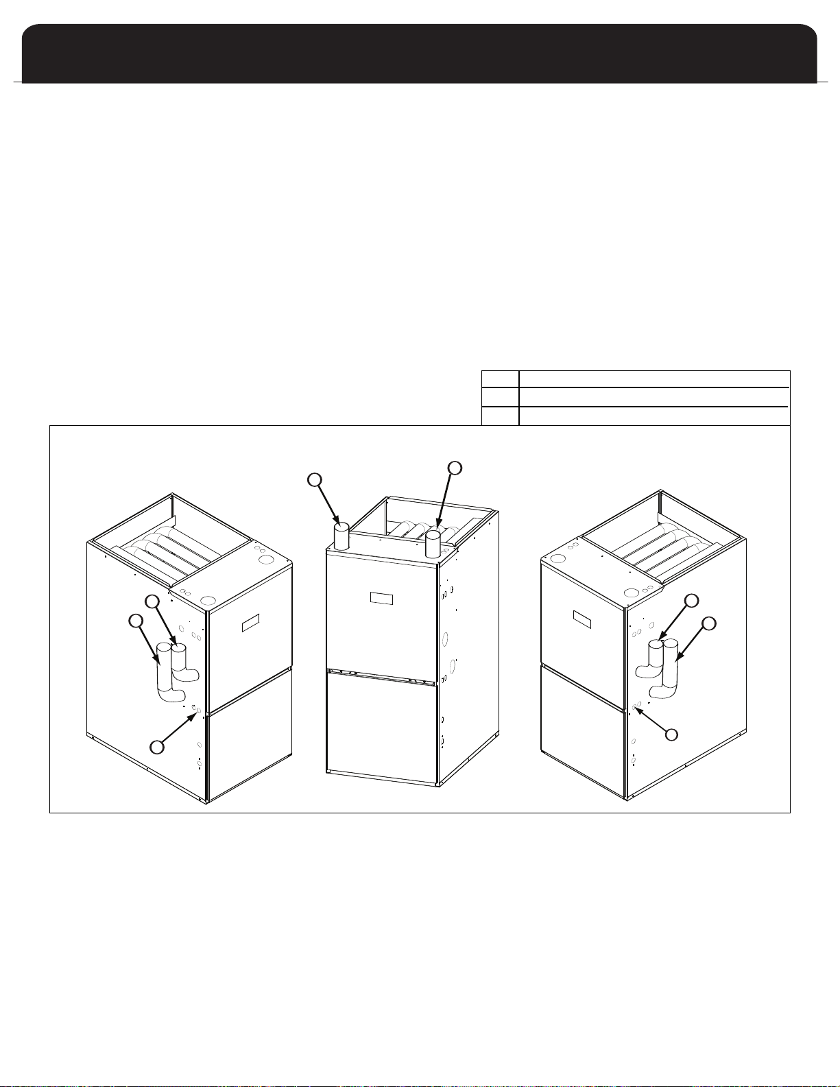
G
A
C
G
B
F
E
D
J
L
L
K
1
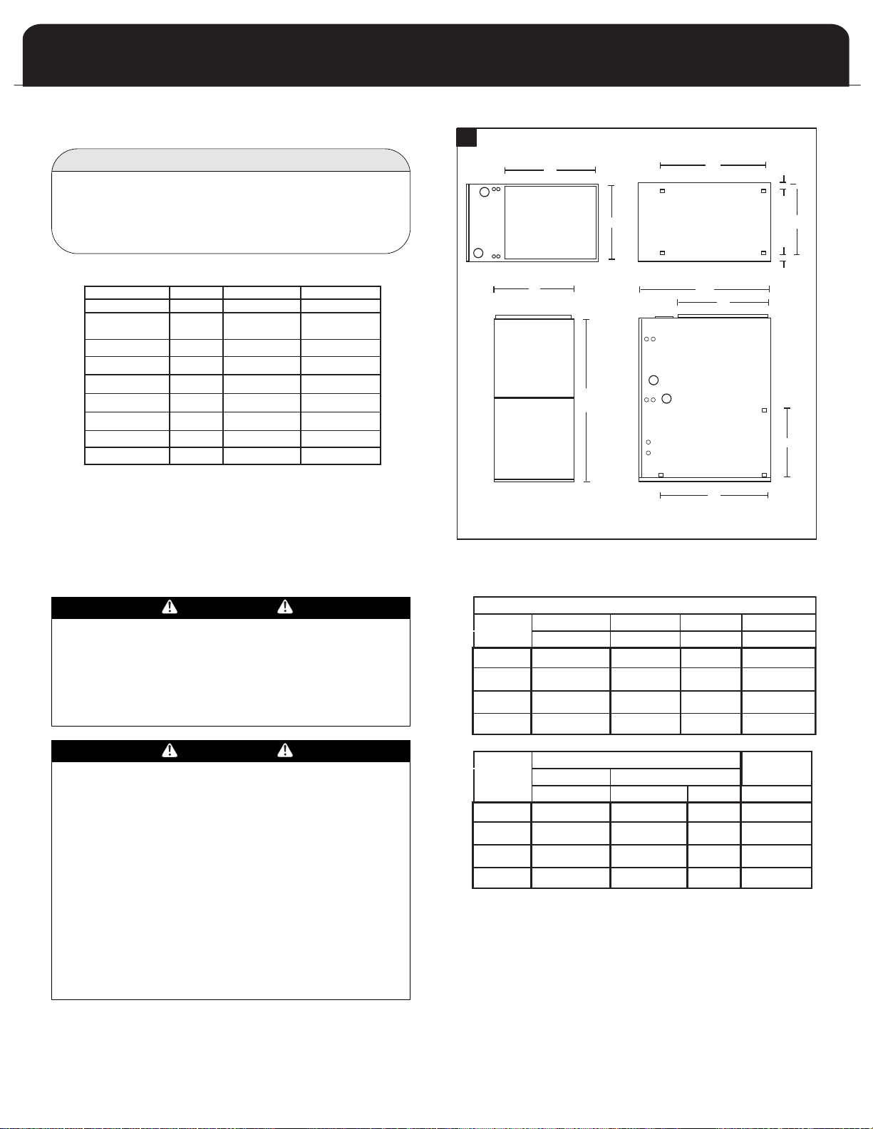
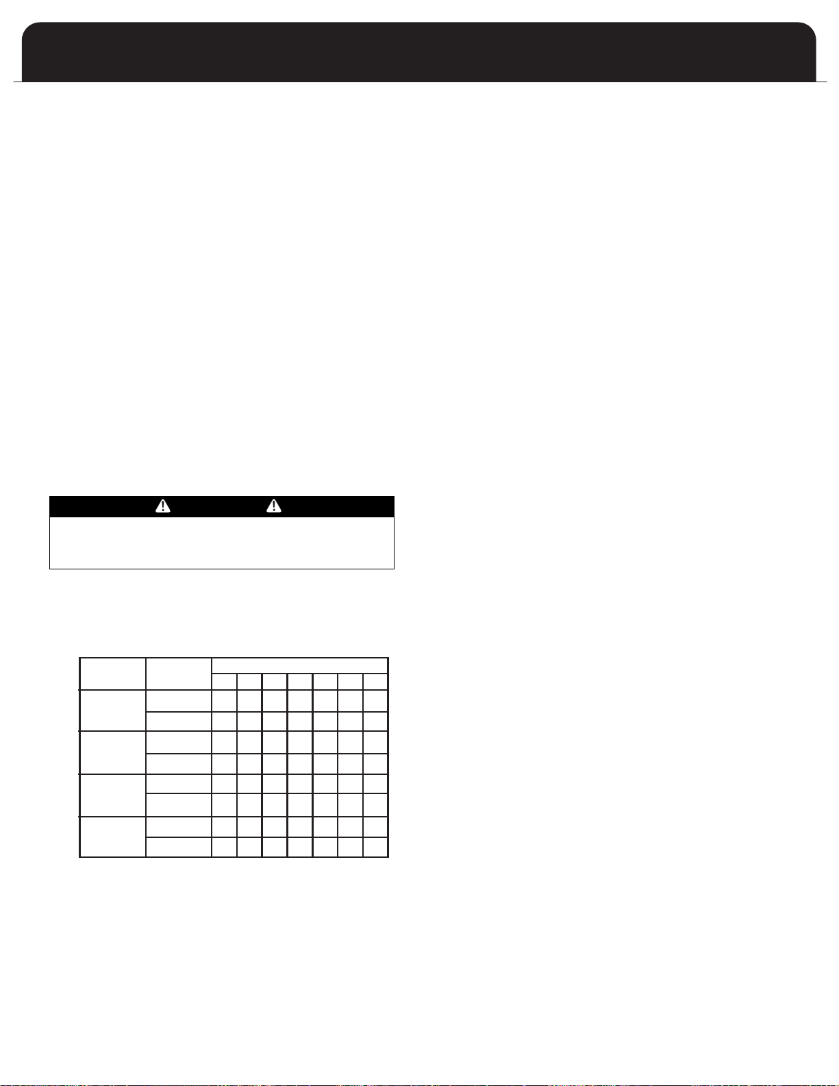
DIMENSIONS (Inches)
MODEL
INPUT
WIDTH DEPTH HEIGHT SUPPLY
ABCFx G
RETURN
SIDE BOTTOM
D x E J x K L H
54,000
72,000
90,000
108,000
54,000
72,000
90,000
108,000
17.5
20.5
20.5
24.5
14 x 22 16 x 19 3/4 2
2
2
2
14 x 22 19 x 19 3/4
14 x 22 19 x 19 3/4
14 x 22 23 x 19 3/4
VENT
29
29
29
29
40
40
40
40
16.5 x 19
19.5 x 19
19.5 x 19
24 x 19
CLEARANCES
0" 0" 0"
LOOKING AT UNIT AS INSTALLED
Table 2 provides the certified clearances to combustibles.
IMPORTANT
This furnace requires a minimum of 24-inches of front
clearance for service purposes. For this purpose, service
learance takes precedence over clearance to
c
combustibles.
TABLE 2: CLEARANCES TO COMBUSTIBLES
TOP
PLENUM
TOP/BOTTOM
PLENUM SIDES
UNIT FRONT
UNIT BACK
UNIT SIDES
UNIT BASE
UNIT FLUE PIPE
ENCLOSURE
* 24" REQUIRED FOR SERVICE
** SUPPLY AIR END / RETURN AIR END
*** CERTIFIED FOR CLOSET INSTALLATION ON COMBUSTIBLE FLOORING
**** CERTIFIED FOR INSTALLATION ON COMBUSTIBLE FLOORING ONLY WHEN INSTALLED
ON SPECIAL BASE PART #30476
UPFLOW
CLOSET
COUNTERFLOW
1"
1" 1"
0.5"
0" *
0" 0"
0" ***
0"
0"
0.5" 0.5"
0" *
0" ****
0"
CLOSET
See the appliance rating plate affixed to the
furnace for specific model number, serial
number and clearance to combustibles
information.
HORIZONTAL
2"
2.5"
0" *
1" **
0"
0"
CLOSET
ALL DIMENSIONS IN INCHES
IGURE 2: DIMENSIONS
F
TABLE 3: DIMENSIONS
COMBUSTIBLE MATERIAL MUST NOT BE PLACED ON OR
AGAINST THE FURNACE JACKET.
PLACEMENT OF COMBUSTIBLE MATERIALS ON, AGAINST
OR AROUND THE FURNACE JACKET CAN CAUSE AN
EXPLOSION OR FIRE RESULTING IN PROPERTY DAMAGE,
PERSONAL INJURY OR LOSS OF LIFE.
THE AREA AROUND THE FURNACE MUST BE KEPT CLEAR
AND FREE OF ALL COMBUSTIBLE MATERIALS INCLUDING
GASOLINE AND OTHER FLAMMABLE VAPORS AND
LIQUIDS.
THE HOMEOWNER SHOULD BE CAUTIONED THA
FURNACE AREA MUST NOT BE USED AS A BROOM
CLOSET OR FOR ANY OTHER STORAGE PURPOSE.
UPFLOW FURNACES ARE DESIGN CER
INSTALLATION ON COMBUSTIBLE FLOORS. THIS SHALL
BE INTERPRETED AS A WOOD FLOOR ONLY.
THE FURNACE MUST NOT BE INSTALLED DIRECTLY ON
CARPETING, VINYL TILE, OR OTHER COMBUSTIBLE
MATERIAL EXCEPT WOOD. INSTALLATION ON
COMBUSTIBLE MATERIAL CAN RESULT IN FIRE, CAUSING
PROPER
DANGER
DANGER
TY DAMAGE, PERSONAL INJUR
T THE
TIFIED FOR
Y OR DEA
TH.
6
DUCTWORK
Proper airflow is required for the correct operation of this
furnace. Insufficient airflow may cause erratic operation,
ould cause the furnace to cycle on the high temperature
c
limit, and may damage the heat exchanger. Excessive
airflow may result in an excessively noisy duct system and
may result in undesirable consequences such as creating
uncomfortable drafts and causing drapes or curtains to
low around.
b
If air conditioning is to be used with the furnace, the duct
system must be capable of delivering the correct amount of
irflow for each system.
a
The ductwork should be sized and constructed in
accordance with accepted industry standards. Duct sizing
and construction information may be obtained from:
• A.C.C.A. (Air Conditioning Contractors of America)
• A.S.H.R.A.E. (American Society of Heating,
Refrigeration and Air Conditioning Engineers)
• H.R.A.I. (Heating, Refrigerating and Air Conditioning
Institute (Canada)
• S.M.A.C.N.A. (Sheet Metal and Air Conditioning
Contractors’ National Association (United States)
All of the above professional organizations have duct sizing
manuals available.
The total static pressure drop of the air distribution system
should not exceed 0.5 inches water column.
Guide:
Filter free area (in2) = 144 x (CFM / desired velocity (fpm))
IMPORTANT
Some high efficiency filters have a greater than normal resistance to airflow. This can adversely affect furnace operation. Pressure check the static differential
from before the filter to the supply.
NOTE
When calculating an air filter size use the free air not
the advertised size.
NOTE
UNITS FOR 4 AND 5 TON CF AIR CONDITIONING MUST
HAVE DUAL RETURN AIR INLETS FOR OPTIMAL
AIRFLOW AND AIR FIL
STATED BY THE FILTER MANUFACTURER, FOR
EFFECTIVE AIR FILTRATION, ASSUME A MAXIMUM
VELOCITY OF 300 FPM FOR DISPOSABLE TYPE FIL
OR 600 FPM FOR PERMANENT TYPE FILTERS.
TION. IF NOT SPECIFICALLY
TRA
TERS,
WARNING
DO NOT, UNDER ANY CIRCUMSTANCES, CONNECT
RETURN OR SUPPLY AIR DUCTWORK TO OR FROM ANY
THER HEAT-PRODUCING DEVICE SUCH AS A FIREPLACE
O
INSERT, STOVE, ETC. DOING SO MAY RESULT IN FIRE,
CARBON MONOXIDE POISONING, EXPLOSION,
PERSONAL INJURY, LOSS OF LIFE, OR PROPERTY
AMAGE.
D
Ductwork Steps:
1. Position the furnace to minimize ductwork length and
fittings.
2. Cut open a return air inlet. The choices are:
a) either side
b) furnace bottom
c) any combination, i.e. two sides or a side and the
bottom.
In all cases, cut the inlet air opening the full width of
NOTE
When two return air inlets are used, both must be
equipped with filters.
CAUTION
DO NOT USE THE REAR PANEL AS A RETURN AIR INLET.
THERE IS INSUFFICIENT AREA TO PERMIT ADEQUATE
AIRFLOW.
3. Install the filter rack(s) (field supplied).
4. Connect the return air duct or fitting to the furnace. The
connection should be as air tight as possible to prevent
entraining combustion gases from an adjacent fuel
burning appliance, or entraining combustion air for this
furnace .
5. Ensure that there is adequate space and accessibility for
the air filter
6. If an air conditioning evaporator coil is required,
position it on the top of the furnace. Ensure that no air
can bypass the evaporator coil.
7. Connect the supply air plenum to the supply air outlet.
Flexible duct connectors are an effective device to
prevent the telegraphing of mechanical noise from the
furnace to other parts of the home via the ductwork. If
using flexible connectors, ensure that the adjoining
duct is independently supported.
Adequate provisions for combustion and ventilation air
must be in accordance with ANSI Z223.1 (NFP
5.3 "Air for Combustion and Ventilation" in the United
States, and CAN/CGA B149 in Canada. Check with local
authorities for any additional building codes, bylaws or
regulations.
.
A 54), section
7
INSTALLATION POSITIONS
he furnace can be installed in any of four positions:
T
• Upflow
• Downflow
• Horizontal left
• Horizontal right
aintain clearances to combustibles as outlined in Table 2.
M
Support the furnace cabinet to prevent twisting or
sagging.
General Considerations
When choosing an installation position the installer must
consider the following connections:
• Combustion air intake
• Exhaust vent
• Gas pipe
• Electrical wiring
• Condensate drain trap
Also consider the air conditioning connections, a/c drain,
access to filter(s) and access to furnace and a/c for repair.
The blower compartment should be completely isolated
from the burner compartment. In tight rooms with other
combustion devices, the blower compartment must be
completely isolated from the room. The combustion
compartment must also be completely isolated from the
room (unless non-direct vent). Sometimes the knockout
tool will punch too deep and open holes. Use caulking on
the inside of the cabinet to seal any holes. Insure that the
combustion door gasket is in good condition.
IMPORTANT
Always secure or support the exhaust vent and
combustion air inlet piping to the floor joists or rafters
to avoid sagging and possible fatigue of venting
materials. This ensures proper drainage and
preventing spilling of the products of combustion into
the building.
IMPORTANT
If the pipe and fittings are to be other than PVC, use
the proper cleaner, primer and cement for the
dissimilar materials.
IMPORTANT
Drains and traps of furnaces installed in spaces
subjected to freezing temperature must also be
protected against freezing.
IMPORTANT
lean and de-burr all pipe cuts. The shavings must not
C
be allowed to block the exhaust, combustion air inlet
r condensate drain lines.
o
Combustion Air Inlet Connection
The combustion air inlet fitting is a 2” PVC Socket to Pipe
Thread adapter. Chose the intake location and open the
appropriate knock out. Install the adapter to the exterior
anel using the gasket on the outside of the panel and the
p
locknut on the inside of the panel.
IMPORTANT
If the pipe is increased in size with a reducer it must
be on a vertical section of the pipe to facilitate draining the vent. Reducing the size of pipe to exit the
house (as shown on page 19, Figures 4 and 6), the
reducer can be on the horizontal.
WARNING
THERE MUST NOT BE ANY OPENINGS BETWEEN THE
BLOWER DIVISION PANEL AND THE COMBUSTION
COMPARTMENT. THE BLOWER COMPARTMENT IS UNDER
GREATER SUCTION THEN THE COMBUSTION
COMPARTMENT AND CAN PULL COMBUSTION AIR FROM
THE BURNERS AND CAUSE INCOMPLETE COMBUSTION
AND ERRATIC FURNACE OPERATION.
IMPORTANT
Keep pressure switch hose above heat exchanger drain
and exhaust port.
Exhaust V
The exhaust vent must be clamped to the exterior panel(s)
with the clamp provided. Place the gasket between the
clamp and the side panel. Tighten clamp and fasten in
place using the three screws provided.
The clamp should secure the vent pipe to prevent internal
damage if the vent pipe is tampered with.
THE VENT MUST BE CLAMPED TO THE FURNACE PANEL
USING THE GASKET AND CLAMP PROVIDED.
THE INTAKE MUST USE THE THREADED PVC
CONNECTOR WITH THE GASKET AND LOCK NUT.
ent Connection
W
ARNING
8
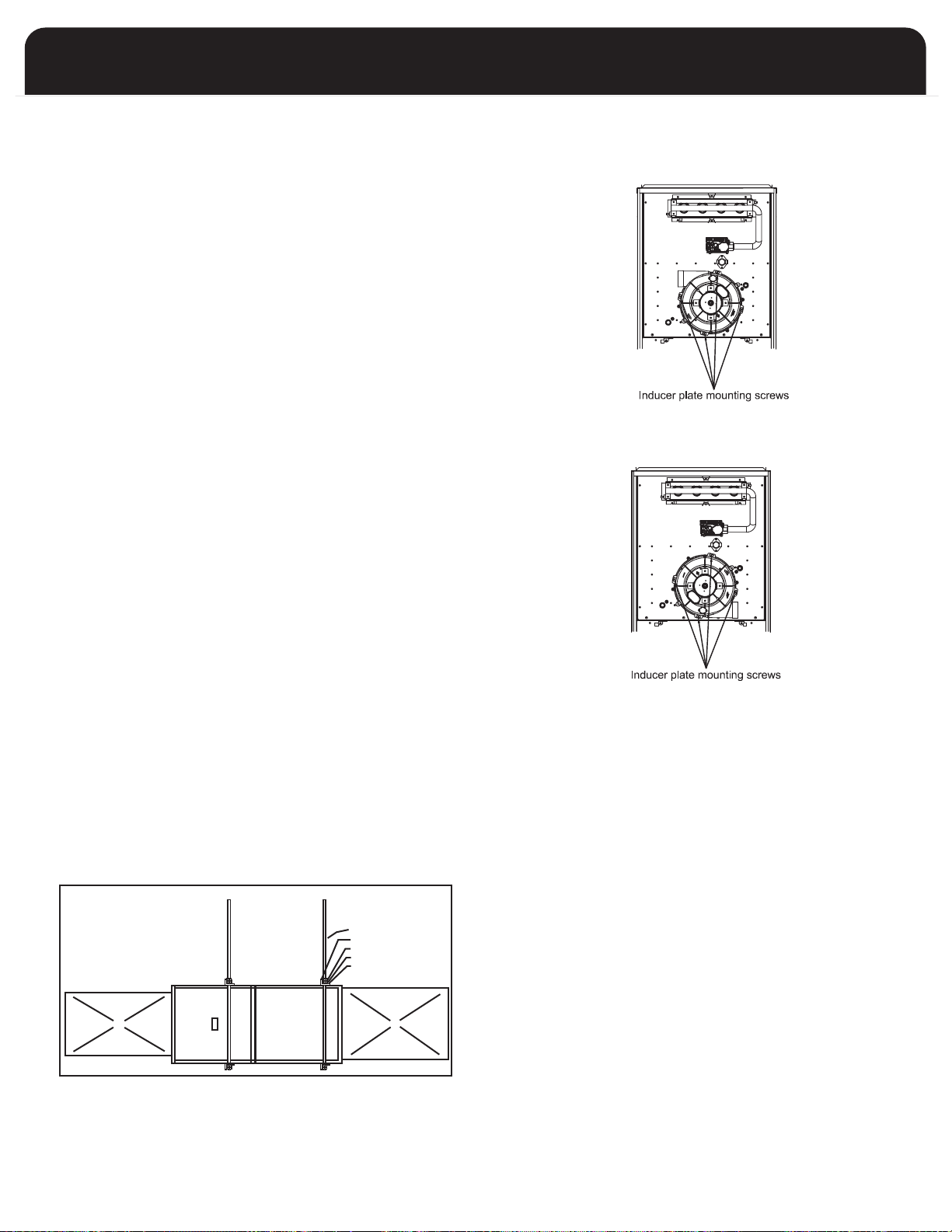
Instructions for Re-orienting Air Inducer
FIGURE A : RIGHT INDUCER POSITION
FIGURE B : LEFT INDUCER POSITION
SUGGESTED METHOD FOR
SUSPENDING HORIZONTAL FURNACE
ALLOW ENOUGH ANGLE
IRON OVERHANG TO
PERMIT OPENING THE
BLOWER DOOR
3/8 INCH THREADED ROD
2 INCH ANGLE IRON
JAM NUTS
LOCK WASHER
FLAT WASHER
SUPPLY AIR PLENUM
RETURN AIR PLENUM
SUSPENDED INSTALLATION
This furnace comes assembled ready for left side or vertical
venting. Rotate the inducer 180 degrees to exit the right
hand side.
1. Disconnect inducer wire connections.
2. Remove pressure switch hoses.
3. Remove pressure switches.
4. Remove 4 inducer screws
5. Remove inducer.
6. Reverse the bands on the rubber drain coupling so the
screws are accessible if necessary. (Do not reverse the
drain coupling.) Confirm that directional arrows on
drain coupling point away from inducer.
7. Remove the appropriate knock out.
8. Reinstall the inducer in the correct orientation with 4
screws removed in step 1.
9. Reinstall the pressure switches so that the switches and
hose is above the heat exchanger drain.
10. Complete the external venting as installation requires.
11. Rotate the drain coupling so the drain holes are angled
downward and tighten coupling bands.
12. Tighten the vent clamp and secure in place using the
screws provided.
INSTALLATION POSITIONS
Non-Suspended Installation
Maintain clearances to combustibles as outlined in Table 2
on page 6. The furnace must be supported in such a way
as to not allow twisting or sagging of the cabinet.
Horizontal Suspended Installation
The furnace may be suspended in either the horizontal right
or left position by field fabricated a cradle of angle iron and
threaded rod. Secure the furnace with 2 inch minimum
slotted angle or equivalent, as shown in figure below. The
furnace must be supported in such a way as not to allow
twisting or sagging of the cabinet. Position the supports so
as not to interfere with accessing the burner and blower
compartments.
9
C
C
A
B
A
B
A
B
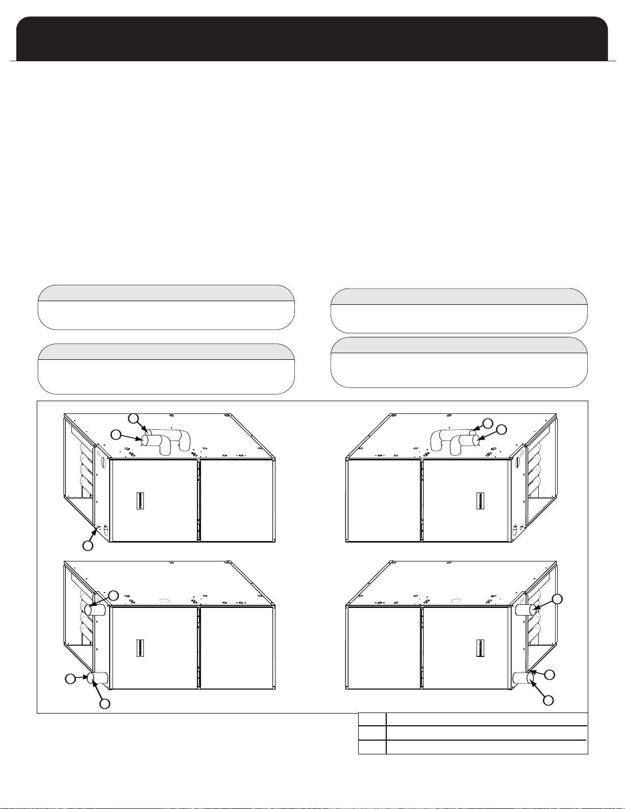
Upflow Installation
The combustion air and exhaust vent may exit through
the top, left or right side of the cabinet when viewed in
the upflow position. The inducer is installed so that the
exhaust vent may exit the top and left sides without
requiring rotation.
f exhaust vent exits the top panel, use the two street
I
elbows to route the vent. One elbow secured to the
inducer drain connector, will angle toward the front of
cabinet with the second nested inside directed towards
the top panel. (The 108,000 BTUH will require an
extension between the inducer and the first elbow that
is not provided.)
If exhaust vent exits the left-side panel the pipe can be
routed straight outside the cabinet.
exists the right-side panel the inducer requires
rotation.
The exhaust vent pipe exiting the cabinet in any
installation should be long enough to install the vent
clamp on the outside of the cabinet.
If exhaust vent
A
COMBUSTION AIR
B
EXHAUST VENT
C
CONDENSATE DRAIN
10

Downflow Installation
When the furnace is installed in the downflow position
the combustion air and exhaust vent may exit through
the left or right side of the cabinet (when viewed in the
upflow position.). The inducer is installed so that the left
side exits require no rotation.
If exhaust vent exits the left-side panel the pipe can be
routed straight outside the cabinet.
If exhaust vent exists the right-side panel the
inducer requires rotation.
The pipe exiting the cabinet in any installation should be
long enough to install the vent clamp on the outside of
the cabinet.
WARNING
WHEN INSTALLED IN THE DOWNFLOW POSITION ON A
COMBUSTIBLE FLOOR, SUBBASE KIT #30476 IS
REQUIRED. FAILURE TO INSTALL SUBBASE KIT COULD
RESULT IN FIRE, DEATH OR SERIOUS INJURY.
The opening in the floor must provide adequate clearances
to the combustible material.
A half-inch of clearance will be required between the
plenum and the combustible material. If installed on a
non-combustible material, zero clearance is required.
In the downflow installation, this furnace can only vent
through the left or right side of the furnace.
The condensate drain trap can be mounted on the right or
left side.
B
B
A
D
C
C
A
COMBUSTION AIR
B
EXHAUST VENT
C
CONDENSATE DRAIN
D
SUBBASE KIT - REQUIRED WHEN
A
D
INSTALLED IN THE DOWNFLOW POSITION
ON A COMBUSTIBLE FLOOR
11
C
A
B
A
A
B
B
B
A
C
C
Horizontal Left Installation
In the horizontal left installation the combustion air and
exhaust vent may exit through the top or left side of the
cabinet (when viewed in the upflow position). It is not
permissible to vent downwards. The inducer is installed
so that the top and left side exits require no rotation.
f exhaust vent exits the top panel, use the two street
I
elbows to route the vent. One elbow secured to the
inducer drain connector, will angle toward the front of
cabinet with the second nested inside directed towards
the top panel. (The 108,000 BTUH will require an
extension between the inducer and the first elbow that
is not provided.)
If exhaust vent exits the left-side panel the pipe can be
routed straight outside the cabinet.
The pipe exiting the cabinet in any installation should be
long enough to install the vent clamp on the outside of
the cabinet.
Horizontal Right Installation
In the horizontal right installation the combustion air
and exhaust vent may exit through the top or right side
of the cabinet (when viewed in the upflow position). In
the horizontal right installation, it is not permissible to
vent downwards.
he right side exit is used.
t
If exiting the top panel, use the two street elbows to
route the vent. One elbow secured to the inducer drain
connector, will angle toward the front of cabinet with
the second nested inside directed towards the top panel.
(The 108,000 BTUH will require an extension between
the inducer and the first elbow that is not provided.)
If exiting the right-side the pipe can be routed straight
outside the cabinet after the inducer has been rotated.
The pipe exiting the cabinet in any installation should be
long enough to install the vent clamp on the outside of
the cabinet.
The inducer will require rotation if
NOTE
It is not permissible to use a rear of the
furnace as a return.
IMPORTANT
The furnace must be installed level or sloping towards
the front to facilitate proper drainage.
NOTE
It is not permissible to use a rear of the
furnace as a return.
IMPORTANT
The furnace must be installed level or sloping towards
the front to facilitate proper drainage.
A
COMBUSTION AIR
B
EXHAUST VENT
C
CONDENSA
12
TE DRAIN
CASE 1:
FURNACE LOCATED IN AN UNCONFINED SPACE
nconfined space does not necessarily mean that combus-
U
tion and ventilation will not have to be introduced from
the outdoors, particularly in airtight homes. Refer to the
appropriate installation code requirements regarding the
minimum combustion air required for all fuel burning
appliances located within the unconfined area.
f the amount of combustion and ventilation air is insuffi-
I
ient to properly operate the furnace and other fuel burn-
c
ing appliances within the unconfined area, it will be necessary to supply it from the outdoors based on the criteria
used when calculating the air supply for a confined space.
NOTE
If planning to use the inside air of an unconfined
space, remember to test for proper furnace operation
(as well as other fuel burning appliances located
within the unconfined space) with respect to adequate
combustion and ventilation air with fireplace dampers
open, clothes dryer running, bathroom exhaust fans
on, kitchen range hood on, etc.
CASE 2:
FURNACE LOCATED IN A CONFINED SPACE
A confined space, (any space smaller than the minimums
discussed in CASE 1), must have two air openings one within 12 inches of the ceiling and the other within 12 inches of
the floor. The air openings must be sized based on whether
the combustion and ventilation air is being taken from
indoors or outdoors, the method outdoor air (if used) is
introduced, and taking into account any other fuel burning
appliances in the confined space.
If sufficient indoor combustion and ventilation air is available for the furnace and all other fuel burning appliances,
even when clothes dryers, bathroom fans, range hoods, etc.
are running, size each opening according to the appropriate installation codes.
NOTE
If using grilles to cover the two openings, factor in the
free area of the grille. Typically, a grille will have a
free area approximately 50% of its nominal size.
Consequently, if the required opening is 10 inches x 10
inches , it will have to be doubled if using a sidewall
grille with 50% free area.
IMPORTANT
CASE 3:
FURNACE LOCATED IN A CONFINED SPACE, OUT-
DOOR
AIR FROM ATTIC OR CRAWL SPACE
In this circumstance, refer to the appropriate installation code for the free area of the combustion and
ventilation air openings. If other fuel burning appli-
nces are present, their combustion air and ventilation
a
ir requirements must be added to those of the fur-
a
ace. If the attic has an exhaust fan (power vent), it
n
may create a negative pressure sufficiently large
enough to prevent the attic from being an effective
source of combustion and ventilation air.
Powered attic fans do not customarily run during the
heating season; however, some are controlled by a
humidistat as well as a thermostat, which may allow
some operation during the heating season.
The choices are (a) use the direct vent option; (b) obtain
outdoor air from elsewhere; or (c) interlock the attic
exhaust fan with the furnace such that the two cannot
operate simultaneously.
CASE 4:
FURNACE LOCATED IN A CONFINED SPACE, OUTDOOR
AIR DUCTED HORIZONTALLY
Similar to CASE 3, outdoor air for combustion and ventilation may be drawn through horizontal ducting.
Consult the appropriate installation code for the free area
for openings. If other fuel burning appliances are present,
their combustion air and ventilation air requirements must
be added to those of the furnace.
IMPORTANT
The outdoor grilles must be installed in a location
where they will not be obstructed in any manner.
If grilles are used on the outside wall, they must be
sized properly. Most sidewall grilles have only 50%
free area, so the grill size opening must be twice the
size of the free air opening requirement.
WARNING
DO NOT ALLOW GAS PIPING TO BE ROUTED THROUGH
JOIST SP
POSES. DO NOT USE JOIST SPACES FOR RETURN AIR
PURPOSES IF THE JOIST SPACE ALREADY CONTAINS
PLUMBING STACKS, CHIMNEY COMPONENTS, ETC.
UNLESS THE PORTION USED FOR RETURN AIR PURPOSES CAN BE COMPLETEL
WITH OTHER USAGES.
ACES THA
T ARE USED FOR RETURN AIR PUR
Y ISOLATED FROM PORTIONS
-
If an exhaust fan, fireplace, clothes dryer or any similar device is present in the indoor area from which the
combustion and ventilation air will be drawn, negative
pressure could be a problem if natural infiltration
from the outdoors does not match the rate at which
air is exhausted.
13
FIGURE 1
FURNACE VENTING
Direct Venting Pipe Connections
(USING OUTDOOR COMBUSTION AIR)
The direct vent configuration is the preferred installation method. The primary advantages are:
• Dedicated combustion air and vent piping eliminates the need to use already heated air for
combustion purposes
• The probability of corrosive contaminants being
present in the combustion air is greatly reduced
• The direct vent configuration is unaffected by
any other appliances, exhaust fans, or other
devices that tend to create negative pressure
conditions while operating
• No vents for combustion and ventilation air are
required in confined spaces
DANGER
DANGER
READ, UNDERSTAND AND FOLLOW ALL INSTRUCTIONS
IN THIS SECTION. FAILURE TO PROPERLY VENT OR
SUPPLY COMBUSTION AIR TO THIS FURNACE CAN
CAUSE CARBON MONOXIDE POISONING, OR AN
EXPLOSION OR FIRE, RESULTING IN PROPERTY DAMAGE,
PERSONAL INJURY OR LOSS OF LIFE.
DANGER
DANGER
THIS FURNACE AND ANY OTHER FUEL BURNING
APPLIANCE MUST BE PROVIDED WITH ENOUGH FRESH
AIR FOR PROPER COMBUSTION AND VENTILATION OF
THE FLUE GASES. MOST HOMES WILL REQUIRE THA
OUTSIDE AIR BE BROUGHT TO THE FURNACE AREA.
FAILURE TO DO SO CAN CAUSE PERSONAL INJURY OR
DEATH FROM CARBON MONOXIDE POISONING.
Combustion Air Inlet Piping
This furnace is certified as a Category I Type FSP Non-
Direct and Direct Vent Furnace. When installed as a direct
vent furnace, all combustion air is supplied from the outdoors via the plastic piping system. All components are
field supplied except for the adapter used to connect the
piping to the furnace.
DANGER
The following types of installation sites (but not limited
to the following) will require OUTDOOR AIR for
combustion because of chemical exposures: commercial
buildings, buildings with indoor swimming pools,
furnaces installed in laundry rooms, furnaces in hobby
r craft rooms, furnaces installed near chemical storage
o
areas.
The combustion air piping, like the exhaust piping, must be
ir tight throughout the system. The adapter joining the
a
ombustion air to the furnace is supplied with a gasket to
c
aintain the seal.
m
IMPORTANT
The supplied adapter is made of PVC. If planning to
use ABS pipe, use an all-purpose cleaner and ABS to
PVC transition cement. If planning to use CPVC pipe,
use an all-purpose cleaner, a clear or purple primer
and all-purpose cement approved for the purpose.
Additional information about cleaners, primers, solvents and cements may be obtained from their manufacturers.
CAUTION
Combustion air must be free of acid forming chemicals
such as sulphur, fluorine and chlorine. These elements
are found in aerosol sprays, detergents, bleaches,
cleaning solvents, air fresheners, paint and varnish
removers, refrigerants, and many other commercial and
household products.
When burned in a gas flame, vapors from these products
form acid compounds. Acid compounds increase the dew
point temperature of the flue products and are highly
corrosive after they condense.
Any furnace failure caused by corrosive elements is
excluded from warranty coverage.
Exposure to the following substances in the combustion
air supply (but not limited to the following) will also
require OUTDOOR AIR for combustion:
•
Aerosols, particularly CFC based or propelled aerosols
• Air fresheners
• Airplane Glue and similar adhesives and cements
• Ammonia, as commonly found in permanent wave
solutions used in hair dressing salons
• Antistatic fabric softeners used in clothes dryers
Carbon tetrachloride
•
Chlorinated cleaners and waxes
•
• Chlorine and bromine based swimming pool chemicals
• Deicing salts or chemicals, e.g. rock salt, etc.
• Dry cleaning fluids such as perchloroethylene
• Fumes from curing polyurethane and similar
substances
• Halogen based refrigerants including R-12 and R-22
• Hydrochloric acid, muriatic acid and other acid based
masonry washing and curing materials
• Printer’s inks, paint removers, varnishes, varsol,
toluene, etc.
Water softener salt and chemicals
•
14
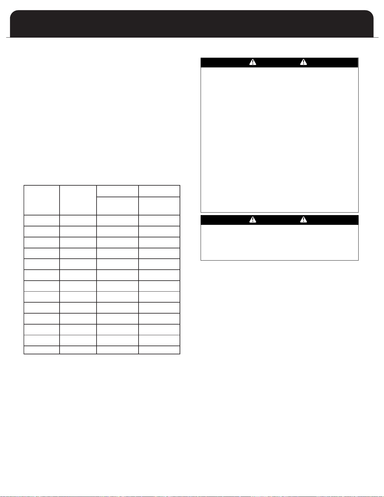
TABLE F
RECOMMENDED AIR FILTER AREA (SQUARE INCHES),
FOR DISPOSABLE AND PERMANENT TYPE FILTERS
COOL
(TONS)
AIR FLOW
(SCFM)
AREA
(INCH2)
AREA
(INCH2)
1.5
2
2.5
3
3.5
4
5
650
810
1000
1150
1350
1550
1750
312
389
480
552
648
744
840
156
194
240
276
324
372
420
919
1226
1532
1839
441
588
735
883
221
294
368
441
HEAT INPUT
(BTU/HR)
54,000
72,000
90,000
108,000
Air Filters
IAQ types of air filters may cause higher static, higher
temperature rise and erratic furnace operation and, with an
ECM drive, can cause blower over speed more noise. Also
he consumer may at some time want to add UV treatment,
t
nd electrostatic air cleaners or HEPA filters. Thus the return
a
duct should be sized larger than traditionally and also more
clearance space allow around the return duct for future
quipment.
e
Angling the air filter is one method of installing a larger
area air filter. Table below shows the recommended air
filter sizes. By examining the table one can see that many
existing installations have undersized air filters, resulting
in poorer air quality.
RECOMMENDED AIR FILTER AREA (SQUARE
INCHES), FOR DISPOSABLE AND PERMANENT
TYPE FILTERS
DISPOSABLE PERMANENT
Exhaust Vent Piping
WARNING
NEVER ALLOW THE PRODUCTS OF COMBUSTION FROM
THE FLUE TO ENTER THE RETURN AIR OR SUPPLY AIR
UCTWORK.
D
ALL RETURN AIR DUCTWORK MUST BE ADEQUATELY
SEALED AND SECURED TO THE FURNACE WITH SHEET
ETAL SCREWS. TAPE THE SHEET METAL SEAMS IN THE
M
VICINITY OF THE FURNACE WITH DUCT TAPE OR
SIMILAR MATERIAL.
WHEN THE FURNACE IS MOUNTED ON A PLATFORM
WITH RETURN AIR THROUGH THE BOTTOM, IT MUST BE
SEALED AIR TIGHT BETWEEN THE FURNACE AND THE
RETURN AIR PLENUM. THE FLOOR OR PLATFORM MUST
PROVIDE SOUND PHYSICAL SUPPORT OF THE FURNACE
WITHOUT SAGGING, CRACKS OR GAPS AROUND THE
BASE, PROVIDING A SEAL BETWEEN THE SUPPORT AND
THE BASE.
FAILURE TO PREVENT PRODUCTS OF COMBUSTION
FROM BEING CIRCULATED INTO THE LIVING SPACE CAN
CREATE POTENTIALLY HAZARDOUS CONDITIONS,
INCLUDING CARBON MONOXIDE POISONING THAT
COULD RESULT IN PERSONAL INJURY OR DEATH.
WARNING
READ AND FOLLOW ALL INSTRUCTIONS IN THIS SECTION. FAILURE TO PROPERLY VENT THIS FURNACE CAN
CAUSE CARBON MONOXIDE POISONING OR AN EXPLOSION OR FIRE RESULTING IN PROPERTY DAMAGE, PERSONAL INJURY OR LOSS OF LIFE.
Definitions
"Vent" and "Chimney" refer to open passageways that
convey vent gases from the furnace, or its vent connector, to
the outside. Vents and chimneys usually run vertically or
nearly vertically. When they serve only one gas appliance,
they are called "dedicated" vents or chimneys. When they
serve multiple gas appliances, they are called "common"
vents or chimneys.
"Vent Connector" refers to a pipe or duct that connects the
furnace to a vent or chimney. Vent connectors usually run
from the furnace’s vent collar to the vent or chimney. Vent
connectors may have vertical and horizontal runs.
"Venting System" refers to a continuous open passageway
from the vent collar to the outside. Venting systems usually
have a vent connector(s) and a vent or chimney
systems commonly serve a single furnace, or a single
furnace and a hot water heater
venting systems are less common.
"Fan Assisted Combustion System" refers to an appliance
equipped with an integral mechanical means to either draw
or force products of combustion through the combustion
chamber and/or heat exchanger. This series furnace uses a
draft inducer to draw combustion products through the
heat exchanger and is considered to have a fan assisted
combustion system. Category I furnaces with fan assisted
combustion systems must not be vented into single wall
metal vents.
. Other multiple appliance
. V
enting
15
CAUTION
FAILURE TO FOLLOW ALL VENTING GUIDELINES MAY
RESULT IN ERRATIC FURNACE OPERATION, FREEZE-UP
OF THE VENTILATION AIR PIPING, OR SOOTING OF THE
FURNACE.
Guidelines
• Venting may be vertical or horizontal.
Minimum vent length - 25 total equivalent feet.
•
(See page 18, Table 4 - Venting Table)
• Horizontal piping must slope back towards the furnace
at a minimum rate of 1/4” to the foot, so that
condensate drains towards the furnace.
• Horizontal runs must be supported at least every 3
feet. Horizontal sections must not dip or sag
• All vent runs through unconditioned space where
freezing might occur should be insulated with 1”
thick, medium density, foil-faced Fiberglass insulation.
An equivalent “arm-aflex” or “rub-a-tex” may also be
used as long as there is no heat tape applied to the
vent pipe. For horizontal runs where water may
collect, wrap the vent pipe with self regulating 3 or 5
watt heat tape. The heat tape must be CSA, UL, or ULC
listed and installed per the manufacturer’s instructions.
• DO NOT COMMON VENT WITH ANY OTHER
APPLIANCE.
• If venting vertically, do not vent up a chimney serving
another appliance or install in a chase with a metal or
high temperature plastic pipe from another gas or fuel
burning appliance unless the required clearances to
combustibles can be maintained between the PVC pipe
and other pipes.
• All exhaust piping must be installed in accordance
with CAN/CGA-B149.in Canada; the latest edition of
National Fuel Gas Code, NFPA 54 / ANSI Z223.1 in the
United States, as well as in accordance with local
codes.
• Take the building orientation and the presence of
other buildings or other nearby structures into
consideration when planning the venting system
location. Certain external structures could create air
turbulence around the vent termination leading to
downdrafts and similar venting problems. In windy
and hill locations, roof venting may improve
operations. Maximum venting length is based on 30
mph winds, areas where higher gusts are dominant it
is suggest to shorten the horizontal vent length,
increase the diameter of the vent, or vent vertically.
The exhaust vent and combustion air intake shall be
•
installed so that both are located in the same wind
pressure zone.
JOINING PIPE AND FITTINGS
Acceptable Materials for Combustion Air and
Exhaust Vent Pipe
The furnace products of combustion include both flue
gases and condensate. All venting and drain materials are
lastic.
p
The combustion air and vent piping and fittings may be
comprised of:
• Schedule 40 PVC, ASTM D1785 or CSA B137.3
• PVC-DWV, ASTM D2665 or CSA B181.2
• ABS-DWV, ASTM D2661 or CSA B181.1
• Schedule 40 CPVC, ASTM F441 or CSA B137.6
In Canada, construct all combustion-air and vent pipes for
this unit of CSA or ULC S636 listed schedule-40 PVC, PVCDWV or ABS-DWV pipe and pipe cement. SDR pipe is not
approved in Canada. In addition, the first three feet of the
exhaust must be accessible for visual inspection.
Procedure for Cementing Joints (ASTM D2855):
It is preferable to use a single type of plastic throughout
the venting and combustion air piping; however, if
dissimilar piping or fitting materials are used, they must be
joined with an appropriate transition cement. Dissimilar
pipe segments may be joined together by mechanical
means (i.e., 2” rubber coupling).
DANGER
SOLVENT CEMENTS AND PRIMERS ARE HIGHLY FLAMMABLE. PROVIDE ADEQUATE VENTILATION AND DO
NOT ASSEMBLE NEAR HEAT SOURCE OR OPEN FLAME.
DO NOT SMOKE. AVOID SKIN OR EYE CONTACT.
OBSERVE ALL CAUTIONS AND WARNINGS PRINTED ON
MATERIAL CONTAINERS. FAILURE TO FOLLOW THESE
GUIDELINES MAY RESULT IN FIRE, EXPLOSION OR ASPHYXIATION CAUSING PERSONAL INJURY OR LOSS OF
LIFE.
WARNING
All pipe, fittings, solvent cement, primers and
procedures must conform to American National
Standards Institute and American Society for Testing
Materials (ANSI / ASTM) standards.
PIPE AND FITTINGS: ASTM D1785, D2466 and D2564
PVC PRIMER AND SOLVENT CEMENT: ASTM D2564
ABS PIPE AND FITTINGS: Use ABS Primer and Solvent
Cement D2235
CPVC SOL
VENT CEMENT
: F493
IMPORTANT
16
For proper installation, DO NOT thin or use solvent
cement that has become curdled, lumpy or thickened.

PROCEDURE:
This guide is intended specifically for PVC pipe; however,
the general procedure applies to all plastic piping systems.
MATERIALS: PVC Cleaner / Primer and PVC Solvent Cement.
IMPORTANT
After cutting pipe, remove all ragged edges and burrs.
This will reduce restriction (pressure drop) throughout
the venting and combustion air system.
Direct Vent Piping Termination
CAUTION
Moisture in the flue gases condenses as it leaves the
terminal. This moisture can freeze on exterior walls, on
soffits, and other nearby objects. Some discoloration is
to be expected; however, improper location or installa-
ion can cause structural or exterior finish damage to
t
he building. Caulk all cracks, seams or joints within a 6
t
foot radius of the termination.
1. Cut the pipe end square. Chamfer edge of pipe. Clean
the fitting socket and pipe joint area of all dirt, grease
and moisture.
2. After checking the pipe and socket for proper fit, wipe
socket and pipe with cleaner / primer. Apply a liberal
coat of primer to inside surface of socket and outside
surface of pipe. DO NOT ALLOW THE PRIMER TO DRY
BEFORE APPLYING THE CEMENT.
NOTE
If alignment is critical, make an alignment mark with a
lead pencil on the outside of the socket to the portion
of pipe beyond the joint. This will allow proper alignment as the joint is processed.
3.
Apply a thin coat of solvent cement to the inside surface of the fitting socket. Quickly apply a heavy coat
of solvent cement to the pipe end and insert it into
the socket with a slight twisting motion until it bottoms out. If alignment is critical, match up the pencil
marks made prior to this step.
NOTE
Cement must be fluid; if not, re-coat.
4. Hold the pipe in the fitting for 30 seconds to prevent
the tapered socket from pushing the pipe out of the
fitting. Failure to do this may result in a weak or leaky
joint.
5. Wipe all excess cement from the joint with a rag.
Allow 15 minutes before handling. Cure time varies
according to fit, temperature and humidity.
NOTE
Stir the solvent cement frequently while using. Use a
natural bristle brush or the dauber supplied with the
container. If a dauber was not supplied, a 1 inch brush
is ideal.
Observe shelf precautions printed on containers. Minimize
the exposure of the container’s contents to air.
For applications below 32°F (0°C), use only low
temperature-type solvent cement.
CAUTION
Improper location or installation can result in structural
damage to the building, damage to the exterior finish
of the building, or may allow recirculation or freezing
of the flue gases onto or into the combustion air
intake. Moisture in the flue gases condenses as it leaves
the terminals. This moisture can freeze on exterior
walls, soffits, and other nearby objects. Some discoloration is to be expected.
General Guidelines
The external portion of the piping in all cases is to consist
of 2” pipe. If 3” pipe is used between the furnace and
terminal, transition to 2” within 18” or less of the exterior
wall.
When 3” pipe is used, exit the cabinet with 2” pipe.
Reduce or increase immediately after exiting the cabinet in
a vertical run making provisions to secure the vent bracket
between cabinet and fitting.
Avoid locating the terminals where the flue gas could
become stagnant and allow recirculation into the
combustion air intake.
Avoid locating the terminal in locations where dripping
condensate may cause problems such as sidewalks, patios,
above planters, near windows where exhaust gases may
cause fogging, etc.
void locating the termination too close to shrubs and
A
other vegetation. The condensate may stunt or kill them.
Caulk all cracks, seams or joints within a 6 foot radius of
the termination.
Do not terminate under a deck unless there is adequate
clearance to prevent damage from the flue gases. A
termination may be located at the end of a patio deck.
Piping running beneath the deck must be suitably
insulated and suspended in a manner to prevent
condensate from collecting and freezing.
Do not locate the terminal on the side of the building
facing the prevailing winter winds.
Avoid locating the terminal in locations where dripping
condensate may cause problems such as side walks, patios,
above planters, near windows where exhaust gases may
cause fogging, etc. Avoid locating the termination too
close to shrubs and other vegetation. The condensate may
stunt or kill them.
The vent terminal should be located no fewer than 6 feet
from an inside corner formed by two exterior walls. A 10
foot distance is recommended.
17
PIPE SIZE
NUMBER OF 90° ELBOWS
MAXIMUM ALLOWABLE
STRAIGHT LENGTH OF EXHAUST OR INTAKE
2
3
2
3
2
3
2
3
0123456
MODEL
054
072
090
108
70
15065140601305512050110451004090
65
140601305512050110451004090
65
140601305512050110451004090
65
140601305512050110451004090
70
150
70
150
70
150
Recommended clearance for overhangs is a minimum of 1
foot vertically for each foot horizontally up to 6 feet.
As a protection against freezing, do not expose a 3 x 2
reducing coupling to outdoor ambient temperatures.
Any adjacent painted surfaces should be in good condition;
no cracks, peeling paint, etc. If wooden surfaces that may
be periodically exposed to flue gases are present, consider
treating with a sealer.
Calculating Piping Length
When calculating allowable vent lengths, be sure to count
all termination fittings in addition to counting the
concentric vent as a straight pipe. The ventilation pipe
extending through the roof must extend 18” above the
highest point where it extends through the roof, surface
and above any obstruction within an 18” horizontal
distance. The ventilation pipe must extend a minimum of
12” above the anticipated snow level.
Exterior vent pipe greater than 24” should be insulated
with 1/2” insulation to prevent moisture from freezing
within the pipe and accumulating.
Size the ventilation pipe as specified in Table 4 - Direct and
Non-Direct Vent Lengths. This table lists the maximum
allowable length of pipe with respect to the number of 90°
elbows used. For the purposes of this calculation, one 90°
elbow is equivalent to two 45° elbows.
WARNING
DO NOT CONNECT FURNACE TO A CHIMNEY OR FLUE
SERVING OTHER APPLIANCES OR A SOLID FUEL BURNING APPLIANCE.
TABLE 4:
VENT LENGTHS- DIRECT/NON-DIRECT VENT LENGTHS
• Count concentric vent fitting as straight pipe.
Use medium or long sweep elbows where possible.
•
One 90
•
• For direct vent, the above is the length allowed for
each vent (intake and exhaust)
• For non-direct vent, the above is length allowed
for exhaust. The intake should have a two inch
upside down “U” intake installed on the cabinet
intake fitting.
elbow is equivalent to two 45
°
elbows.
°
18

A
B
C
D
E
A
B
D
F
A
A
B
B
G
E
E
D
A
A
B
B
G
TERMINATION OF COMBUSTION AIR
AND VENTILATION PIPE USING A
CONCENTRIC VENTING KIT
oncentric venting terminal kits may be used for this series
C
urnace. They provide a means of obtaining combustion air
f
nd exhausting products of combustion utilizing a single
a
penetration through the exterior wall. This can be useful
when there is limited wall space available. Kits are available
in 2” and 3” sizes. Read the instructions supplied with the kit
for additional installation instructions and details.
he concentric venting terminal has the combustion air intake
T
uilt into the assembly. If using the concentric vent terminal,
b
here must be a minimum of 12” clearance to grade or antici-
t
pated snow level. There are no means available to raise the
terminal externally. If planning to use this terminal kit, see
Figures 5 and 6.
The concentric vent termination kits may also be used in the
vertical position.
Figure 3
A
B
C
D
VENT
COMBUSTION AIR
AIN 12” CLEARANCE
MAINT
(18” FOR CANADA) ABOVE HIGHEST
ANTICIP
A
TED SNOW LEVEL.
MAINTAIN 12” CLEARANCE
(18” FOR CANADA) ABOVE HIGHEST
Figure 4
E
F
G
STRAP (FIELD SUPPLIED)
1” MAXIMUM
ELBOW (FIELD SUPPLIED)
Figure 5
Figure 6
ANTICIPATED SNOW LEVEL. MAXIMUM
24” ABOVE ROOF.
19

HORIZONTAL TERMINATION OF COMBUSTION AIR
TOP VIEW
INTERIOR
EXTERIOR
C
D
J
A
B
I
F
H
A
A
C
D
E
E
D
B
B
D
G
AND EXHAUST VENT
orizontal Combustion Air Termination
H
The combustion air termination is a 2” medium or long
sweep 90° elbow pointing downward to prevent rain from
readily entering the combustion air intake piping. An
intake screening is optional; however, unless there is a
compelling reason to use one, the screen may actually
ncourage the formation of rime ice, which could cause
e
he intake to become blocked in certain weather
t
onditions.
c
Horizontal Exhaust Vent Termination
Horizontal vents should pass through the exterior wall.
Figure 8 shows a standard horizontal vent detail. Terminate
the vent approximately 8” or more from the wall. If it is
not possible to obtain proper clearance to grade or anticipated snow level by a straight out configuration, the termination may be raised by the use of a pair of 90° elbows.
The exhaust termination is normally a 2” 45° elbow or a
medium or long sweep 90° elbow pointing within 45° of
the downward position, away from the combustion air
intake terminal.
If the required clearance to grade or anticipated snow level
cannot be obtained with the “straight through”
c
2
gases may be expelled horizontally. Use the same size pipe
as the interior run and count the fittings and length as
part of the total vent length.
If winter prevailing wind conditions are variable and likely
to occasionally blow flue gases back in on the combustion
air intake, the exhaust termination may be raised 18-24”
above the combustion air intake terminal to take
advantage of the natural buoyancy of the flue gases to
help prevent re-circulation of the exhaust. (Figure 9)
If the required clearance to grade or anticipated snow level
cannot be obtained with the “straight through” configuration, the combustion air intake pipe may be “periscoped”
up to 24” to gain extra height (Figure 9)
onfiguration, the exhaust pipe may be “periscoped” up to
4” to gain extra height. (Figure 9) In this case, the flue
NOTE
Length of pipe and elbows count toward maximum
allowable vent length as shown in Table 4.
Figure 7
A
EXHAUST VENT
B
COMBUSTION AIR
C
8”
D
12”
E
2”
F
12” CLEARANCE ABOVE GRADE OR
Figure 9
ANTICIPATED SNOW LEVEL
Figure 8
20
G
12”- 18”
H
GRADE OR ANTICIPATED SNOW LEVEL
I
18” MAX
J
OUTSIDE WALL
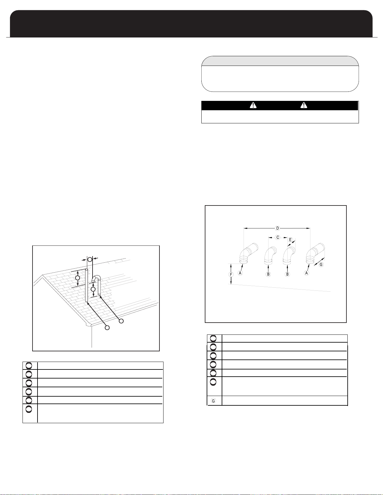
D
E
F
A
B
C
D
E
F
A
B
C
TOP VIEW
INTERIOR
EXTERIOR
C
D
J
A
B
I
F
H
A
E
E
D
B
VERTICAL TERMINATION OF
A
B
C
TOP VIEW
INTERIOR
EXTERIOR
C
D
J
A
B
I
A
B
E
D
C
F
H
A
A
C
D
E
E
D
B
D
G
COMBUSTION AIR
AND EXHAUST VENT
Vertical Combustion Air Termination
he combustion air termination is a pair of 2” medium or
T
ong sweep 90° elbows pointing downward to prevent rain
l
from entering the combustion air intake piping.
If 3” piping is used, it should be reduced to 2” within 18”
of the point where the pipe penetrates the roof. The termination inlet must be positioned within 3” of the companion exhaust piping.
The combustion air inlet must be located a minimum of
12” above the anticipated snow level, and 12” below the
exhaust outlet.
ertical Exhaust Vent Termination
V
The exhaust vent may terminate in a vertical venting
configuration through the roof.
No termination fitting is required if venting vertically
through a roof. The end of the exhaust pipe must be 12”
higher than the entrance of the combustion air intake
terminal.
The exhaust pipe extending through the roof must extend
a minimum of 18” above any obstruction within an 18”
horizontal distance.
MULTIPLE VENTING
IMPORTANT
When installing multiple furnaces in close proximity,
each requires dedicated combustion air and exhaust
venting.
WARNING
COMMON VENTING IS PROHIBITED
If two of these furnaces are to be installed in close proximity, the combustion air intake and exhaust terminations may
be installed as shown in Figures 10.
If more than two furnaces are being installed in close proximity, each additional combustion air intake and exhaust
termination set must be installed a minimum of 4 feet
apart. This is an exception to the 10 foot requirement mentioned in the “Location” section on the previous page. If
using the concentric venting kits, two terminals may be
centered 12 inches apart.
Figure 10
COMBUSTION AIR
EXHAUST
8”
12”
2”
12” CLEARANCE
HIGHEST ANTICIPATED SNOW LEVEL.
ABOVE GRADE OR
COMBUSTION AIR
EXHAUST
8”
12”
2”
12” CLEARANCE
HIGHEST ANTICIPATED SNOW LEVEL.
8”
ABOVE GRADE OR
21

NON-DIRECT VENT FURNACE
INSTALLATIONS
(USING INDOOR COMBUSTION AIR)
The furnace, although designed as a direct vent type
appliance, may be installed with the intake vent inside
the structure. Non-direct vent installations require only an
exhaust vent pipe.
on-direct venting may be desirable when:
N
• Using outdoor combustion air is not practical
• The furnace is in a garage or attic
• Provisions are not made for routing of combustion air
• The outdoor environment may contain contaminants
undesirable for combustion
WARNING
THIS FURNACE AND ANY OTHER FUEL BURNING
APPLIANCE MUST BE PROVIDED WITH ENOUGH FRESH
AIR FOR PROPER COMBUSTION AND VENTILATION OF
THE FLUE GASES. MOST HOMES WILL REQUIRE THAT
OUTSIDE AIR BE BROUGHT TO THE FURNACE AREA.
FAILURE TO DO SO CAN CAUSE PERSONAL INJURY, OR
DEATH FROM CARBON MONOXIDE POISONING.
DANGER
SOLVENT CEMENTS AND PRIMERS ARE HIGHLY
FLAMMABLE. PROVIDE ADEQUATE VENTILATION AND DO
NOT ASSEMBLE NEAR HEAT SOURCE OR OPEN FLAME. DO
NOT SMOKE. AVOID SKIN OR EYE CONTACT. OBSERVE ALL
CAUTIONS AND WARNINGS PRINTED ON MATERIAL
CONTAINERS. FAILURE TO FOLLOW THESE GUIDELINES
MAY RESULT IN FIRE, EXPLOSION OR AS-PHYXIATION
CAUSING PERSONAL INJURY OR LOSS OF LIFE.
Connecting a Non-Direct Vent to the Furnace
When using indoor air or the non-direct vent
configuration, the combustion air inlet to the furnace must
be protected from blockage. Use a double elbow
arrangement if supplying combustion air through the top,
or a downward pointing single elbow if supplying
combustion air through the side.
WARNING
READ AND FOLLOW ALL INSTRUCTIONS IN THIS SECTION. FAILURE TO PROPERLY VENT THIS FURNACE CAN
CAUSE CARBON MONOXIDE POISONING OR AN EXPLOSION OR FIRE RESUL
SONAL INJURY OR LOSS OF LIFE.
TING IN PROPERTY DAMAGE, PER-
IMPORTANT
f the furnace is to be installed in the vicinity of other
I
fuel burning appliances, adequate combustion air
must be available for the non-direct vent appliances.
See Section 10 of this manual, “Determining
Combustion Air.”
IN THE U.S.A.
In addition to the general guidelines, in the United States,
the non-direct vent exhaust shall be installed in accordance
with the following:
• The clearance from the bottom of the terminal to grade
shall be 12” or increased to maintain 12” above the anticipated accumulated snow level.
• The vent shall not terminate over public walkways or
over an area where condensate or vapor could create a
nuisance or hazard.
• The vent terminal shall be installed 4 feet below, 4 feet
horizontally from, or 1 foot above any door, window, soffit, under eave vent or gravity air inlet to the building.
• The vent terminal shall have a minimum horizontal clearance of 4 feet from electric meters, gas meters, regulators
and relief equipment.
• Locate the vent terminal 3 feet above any forced air inlet
located within 10 feet. Any fresh air or make-up air inlet,
such as for a dryer or furnace area is considered a forced
air inlet. The vent terminal should be located no fewer
than 6 feet from an inside corner formed by two exterior
walls; a 10 foot distance is recommended.
Recommended clearance from overhangs is a minimum of
1 foot vertically for each foot horizontally up to 6 feet.
IN CANADA
In addition to the general guidelines, in Canada, the nondirect vent exhaust shall not terminate:
• Directly above a paved sidewalk or paved driveway
which is located between two single-family dwellings
and serves both dwellings;
• Less than 7 feet above a paved sidewalk or paved
driveway located on public property;
• Within 6 feet of a mechanical air supply inlet to any
building;
•
Above a meter/regulator assembly within 3 feet
horizontally of the centerline of the regulator;
• Within 6 feet of any service regulator vent outlet;
• Less than 12” above grade level or anticipated snow
level;
• Within 12” of any door, window, or non-mechanical air
supply inlet to any building;
Within 12” of the combustion air inlet of any other
•
appliance;
• Underneath a veranda, porch or deck, unless (a) the
veranda, porch or deck is fully open on a minimum of
two sides beneath the floor, and (b) the distance
between the top of the vent termination and the
underside of the veranda, porch or deck is greater
than 12”.
22

A vent shall not terminate directly above a sidewalk or paveble Cell Footnoted driveway that is located between two single
Other Then Direct Vent Terminal Clearances
A = Clearance above grade, veranda, 12 in (30 cm) 12 in (30 cm)
porch, deck, or balcony
B = Clearance to window or door that 6 in (15 cm) for appliances 10,000 4 ft (121 cm) below or to side of
may be opened Btuh (3 kW), 12 in (30 cm) for opening; 1 ft (30 cm) above opening
C = Clearance to permanently closed * *
window
D = Vertical clearance to ventilated soffit * *
located above the terminal within
a horizontal distance of 2 ft(61 cm )
from the center line of the terminal
E = Clearance to unventilated soffit * *
F = Clearance to outside corner * *
G = Clearance to inside corner * *
H = Clearance to each side of center 3 ft (91 cm) within a height 15 ft *
line extended above ( 458 cm) above the meter / regulator
meter/regulator assembly assembly
I = Clearance to service regulator 3 ft (91 cm) *
vent outlet
J = Clearance to nonmechanical air 6 in (15 cm
supply inlet to building or t he (3 kW),12 in (30 cm) for appliances > opening; 1 ft (30 cm) above
combustion air inlet to any other 10,000 Btuh (3 kW) and 100,000 Btuh opening
appliance (30 kW), 36 in (91 cm) for appliances
K = Clearance to a mechanical air supply 6 ft (183 cm) 3 ft (91 cm) above if within 10 ft
inlet (305 cm) horizontally
L = Clearance above paved sidewalk or 7 ft (213 cm) ** 7 ft (213 cm)
paved driveway located on public
property
M = Clearance under veranda, porch 12 in (30 cm) *** *
deck. or balcony
For clearances not specified in ANSI Z223.1/NFPA 54 or CSA B1 49.1, the following statement shall be included:
*
appliances > 10,000 Btuh (3 kW) and
100,000 Btuh (30 kW), 36 in (91 cm)
for appliances > 100,000 Btuh (30 kW)
) for appliances 10,000 Btuh 4 ft (121 cm) below or to side of
> 100,000 Btuh (30 kW)
"Clearance in accordance with local installation codes and the requirements of the gas supplier and the manufacturer's
installation instructions."
Canadian Installations US Installations
**
family dwellings and serves both dwellings
Permitted only if veranda, porch ,deck, or balcony is fully open on a minimum of two sides beneath the floor.
***
23
232

Direct Vent Terminal Clearances
Canadian Installations US Installations
A = Clearance above grade, veranda, 12 in (30 cm) 12 in ( 30cm )
porch, deck, or balcony
B = Clearance to window or door that 6 in (15 cm) for appliances 10,000 6 in (15 cm) for appliances 10,000
may be opened Btuh (3 kW),12 in (30 cm) for Btuh (3 kW), 9 in (23 cm) for
C = Clearance to permanently closed * *
window
D = Vertical clearance to ventilated soffit * *
located above the terminal within
a horizontal distance of 2 ft(61 cm)
from the center line of the terminal
E = Clearance to unventilated soffit * *
F = Clearance to outside corner * *
G = Clearance to inside corner * *
H = Clearance to each side of center 3 ft (91cm ) within a height 15 ft *
line extended above (457 cm) above the meter / regulator
eter/regulator assembly assembly
m
I = Clearance to service regulator 3 ft (91 cm)
vent outlet
J = Clearance to nonmechanical air 6 in (15 cm) for appliances 10,000 Btuh 6 in (15 cm) for appliances 10,000 Btuh
supply inlet to building or the (3 kW),12 in (30 cm) for appliances > (3 kW ), 9 in (23 cm) for appliances >
combustion air inlet to any other 10,000 Btuh (3 kW) and 100,000 Btuh 10,000 Btuh (3 kW) and 50,000 Btuh
appliance (30 kW ), 36 in (91 cm) for appliances (15 kW), 12 in (30 cm) for appliances
K = Clearance to a mechanical air supply 6 ft (183 cm) 3 ft (91 cm) above if within 10 ft
inlet (305 cm) horizontally
L = Clearance above paved sidewalk or 7 ft (213 cm) ** *
paved driveway located on public
property
M = Clearance under veranda, porch 12 in (30 cm) *** *
deck or balcony
appliances > 10,000 Btuh (3 kW) and appliances > 10,000 Btuh (3 kW)
100,000 Btu (30 kW), 36 in (91 cm) and 50,000 Btuh (15 kW), 12 in (30 cm)
for appliances > 100,000 Btuh (30 kW) for appliances > 50,000 Btuh (15 kW)
> 100,000 Btuh (30 kW) > 50,000 Btuh (15 kW)
For clearances not specified in ANSI Z223.1/NFPA 54 or CSA B1 49.1, the following statement shall be included:
*
"Clearance in accordance with local installation codes and the requirements of the gas supplier and the manufacturer's
installation instructions."
**
A vent shall not terminate directly above a sidewalk or paved driveway that is located between two
single family dwellings and serves both dwellings
*** Permitted only if veranda, porch ,deck, or balcony is fully ope
n on a minimum of two sides beneath the floor.
23
24

CONDENSATE DRAINS
The furnace will condense as much as a half pound of
water per hour (approximately 2 imperial quarts, 2
quarts or 2
draining the condensate away.
The furnace is supplied with a drain trap assembly. See
page 26, Figures 11-14 for possible locations of the drain trap.
The drain coupling on the inducer will work better if the
drain holes are pointed down about 15 degrees. The drain
hose supplied with the furnace is long enough to reach
either side panel; however, it must be cut near the blower
division panel and fitted with the elbows and clamps provided. This is to prevent kinking in the drain lines.
1
/4liters). It is necessary to make provisions for
1
/2U.S.
DRAIN PIPING
ondensate from the outlet of the drain trap assembly
C
must be conveyed to a floor drain, sump pit, or, if these are
unavailable, to a condensate pump. If using a condensate
pump, be sure that it is approved for use for furnace
ondensate.
c
CAUTION
Do not drain the condensate outdoors. Do not run the
condensate line through areas where freezing might
occur. Freezing of condensate can result in erratic furnace operation and in property damage.
CAUTION
The two inlets to the drain trap are for vent pipe and
condensate collection. The vent pipe inlet is smaller
than the condensate collection inlet. Ensure that the
drain hoses are properly connected.
DRAIN HOSE INST
1. Select a drain trap location suitable for the orientation
of the furnace and remove the corresponding knockouts. See page 26, figures 11-14.
2. Affix the drain trap assembly to the exterior of the side
panel when the furnace is upflow or downflow using
two screws provided. For horizontal positions the
installer will need to use the mounting bracket supplied and secure the bracket to the top panel. Remove
two top panel screws and fasten bracket to top panel
with removed screws. Secure trap assembly using
screws provided to the mounting bracket.
2. Slide a hose clamp over the end of each hose.
3. Slide each hose over the appropriate inlet.
4. Slide each hose clamp to approximately 1/8” from the
end of the hose.
5. Fasten each drain hose to its inlet by tightening the
hose clamps.
6. Cut each drain hose near the blower division panel, at
the point where kinking is able to occur.
7. Slide a hose clamp over the ends of the hose connect
ing to the vent drain and condensate drain.
8. Insert an end of the plastic elbow (supplied) into each
hose.
Cut hose lengths from the remaining lengths of hose
9.
to fit between elbows and the drain trap inlets of both
the vent drain and the condensate drain.
10. Slide a hose clamp over the ends of the hoses and
secure to their appropriate connection.
Slide each hose clamp to approximately 1/8” to 1/4”
from the end of the hose then tighten.
ALLATION
-
The condensate drainage configuration requires a vent. It
takes less than a one inch rise anywhere along the horizontal route of the drain tube to create a vapor lock, which
will prevent condensate from draining away freely, and
result in erratic furnace operation.
IMPORTANT
If an air conditioning evaporator coil drain is to share
the furnace drain line, it should be connected with a
tee fitting down-stream from the trap. Do not connect
the evaporator coil condensate drain upstream of the
furnace drain trap assembly
FIGURES 11-14 : CONDENSATE TRAP / CONDENSATE
DRAINAGE WITH VENT.
(NEXT PAGE)
.
CAUTION
Ensure that drain hoses do not create traps prior to the
condensate trap assembly. A secondary trap will cause
intermittent operation due to the pressure switches
opening.
25

HORIZONTAL FLOW RIGHT
CONDENSATE TRAP
CONDENSATE TRAP
HORIZONTAL FLOW LEFT
UPFLOW
DOWNFLOW
CONDENSATE
CONDENSATE TRAP
TRAP
FIGURE 11 FIGURE 12
FIGURE 13
FIGURE 14
26

D
E
A
B
C
CONDENSATE DRAIN INSTALLATION
1. Identify which side the condensate drain trap will be
nstalled on the unit. Condensate trap may be mount-
i
ed on either the left or right side of the unit, when
looking at the front. Some installation positions will
only allow one option to mount the drain.
. Using the appropriate template (left vs. right), mark
2
the mounting and drain holes.
. Drill holes and de burr, if necessary
3
4. Secure the condensate drain trap to the side of the fur-
ace using the mounting holes that were just drilled
n
5. Install one rubber grommet (provided) into each of the
drain holes and then insert the 90 degree (black) drain
tubes so that they extend down into the top of the
drain trap.
Inside the top front cover, connect the drain tubing
from the flue connector to one of the drain pipes that
were just installed.
Do the same for the second drain pipe located located
in the lower right of the inner front panel. 1/2 ID tubing should be used. It may be necessary to secure the
tubing with a hose clamp depending on the fit. Be
cautious not to over tighten the clamp.
7. Pipe the remainder of the drain to the condensate
pump using PVC pipe. A 3/4” PVC coupling will fit over
the drain connection on the trap.
IMPORTANT
The condensate drain trap assembly should be full of
water before starting the furnace.
CONDENSATE NEUTRALIZERS
Some local codes may require the use of a condensate neutralizer. If the furnace condensate is to be routed to a septic system, it may be advisable to use a condensate neutralizer.
Condensate neutralizers such as the Ward Industries 90+
Neutralizer are available through heating supply wholesalers.
When condensate neutralizers are used, it is advisable to
install it with an overflow bypass tube.
A - Condensate
Trap Assembly
B - Open to
Atmosphere
C - Standpipe (1/2"
PVC)(Minimum 1"
Higher than Trap
Assembly)
D - Tee(1/2" PVC)
E - Overflow
Bypass Tube
27

AS SUPPLY
G
WARNING
THIS FURNACE IS FACTORY EQUIPPED TO BURN NATURAL
GAS ONLY.
CONVERSION TO L.P. GAS REQUIRES SPECIAL KIT No.
194301570001.
AILURE TO USE THE PROPER CONVERSION KIT CAN
F
CAUSE FIRE, EXPLOSION, CARBON MONOXIDE
POISONING, PROPERTY DAMAGE, PERSONAL INJURY OR
LOSS OF LIFE.
CAUTION
CONVERSION OF THIS FURNACE REQUIRES SPECIALIZED
EQUIPMENT. A TRAINED AND QUALIFIED INSTALLER,
SERVICE AGENCY OR GAS SUPPLIER MUST COMPLETE
CONVERSION.
CAUTION
CONNECT THIS FURNACE ONLY TO GAS SUPPLIED BY A
COMMERCIAL UTILITY OR SUPPLIER. PRIVATE GAS WELLS
DO NOT GENERALLY PROVIDE GAS WITH CONSISTENT,
UNIFORM AND PREDICTABLE HEATING VALUES AND
DENSITIES. MANY NON-COMMERCIAL WELLS CONTAIN
IMPURITIES SUCH AS SULPHUR, WHICH MAY DAMAGE
THE FURNACE. THIS FURNACE CANNOT OPERATE
PROPERLY OR SAFELY USING FUELS OUTSIDE NORMAL
COMMERCIAL STANDARDS.
Gas Piping
In the United States, the gas piping should be installed in
accordance with ANSI Z223.1 / NFPA 54 and any local codes.
In Canada, the gas piping should be installed in accordance
with CAN/CSA-B149, and in accordance with any local codes.
The gas piping may enter the furnace from either side.
Install a BMI ground joint union between the gas valve and
the side panel to allow easy removal of the burner for
service purposes.
Install a manual gas shutoff valve and drip leg as close to
the furnace as possible. Some local codes call for the
manual gas shutoff valve to be located between 4 to 5 feet
above floor level to prevent tampering by small children.
Ensure that the valve is readily accessible.
If local codes allow the use of a flexible gas appliance
connector, always use a new listed connector. Do not use a
connector which has previously serviced another gas
appliance.
CAUTION
ENSURE THAT THE MANUAL SHUTOFF VALVE AND GAS
VALVE ARE NOT SUBJECTED TO HIGH PRESSURES.
DISCONNECT THE MANUAL SHUTOFF VALVE AND GAS
VALVE DURING ANY PRESSURE TESTING THAT EXCEEDS
1/2 P.S.I.G. (3.45 KPA
The natural gas inlet supply pressure should be 5 to 10.5
inches water column (w.c.); 7 inches w.c. is recommended.
The L.P. gas inlet supply pressure should be 11 to 13 inches
w.c.; 12 inches w.c. is recommended.
These pressures must be maintained while all other gas
fired appliances are operating at maximum conditions.
Do not exceed 13 inches w.c. inlet pressure with LP. Do not
exceed 10.5 inches w.c. inlet pressure with NG.
The gas valve has an adjustable internal regulator for
controlling burner manifold pressure. Burner manifold
pressure is listed on the furnace rating plate.
).
Leak Testing
All new gas piping installations should be pressure tested as
specified by CAN/CGA-B149 or NFPA 54 ANSI Z223.1 or
ANSI/NFPA 58, Standard for the Storage and Handling of
Liquefied Petroleum Gases.
IMPORTANT
YS USE A BACKUP WRENCH TO PREVENT
A
W
AL
TWISTING OF THE CONTROL ASSEMBLY AND GAS
VALVE. ANY STRAINS ON THE GAS VALVE CAN AFFECT
POSITIONING OF THE ORIFICES RELATIVE TO THE
BURNERS. THIS COULD RESUL
OPERATION.
T IN F
AULTY BURNER
28

Gas piping that has not been pressure tested, from the
GAS VALV E
manual shutoff valve to the furnace gas valve for example,
should be leak tested using an electronic combustible gas
detector, a commercially prepared leak detector such as Gas
Leak Detector® or Search®, or other locally approved
method. A leak detector solution can be prepared by mixing
small quantity of dish detergent with water and daubing
a
t onto the gas piping and connections.
i
WARNING
NEVER PURGE A GAS LINE INTO THE COMBUSTION
CHAMBER.
NEVER USE A MATCH, TAPER, CIGARETTE LIGHTER,
FLAME OR ANY OTHER IGNITION SOURCE TO CHECK
FOR LEAKS IN A GAS LINE.
FAILURE TO ADHERE TO THIS WARNING CAN CAUSE A
FIRE OR EXPLOSION RESULTING IN PROPERTY DAMAGE,
PERSONAL INJURY, OR LOSS OF LIFE.
CONVERSIONS
High Altitude
In the United States, the modifications for high altitude are
based on a 4 percent reduction of input capacity for every
1000 feet above sea level. Table on page 30 illustrates
the impact of altitude for selected elevations. Ratings
shown apply to the highest elevation in range.
Consult with local fuel suppliers or authorities to determine
local regulations or customs.
In Canada, the furnace may be converted for high altitude
(2000 - 4500 feet) by changing the burner orifices. Use Kit
No. 30552. The kit contains both natural gas and L.P. gas
orifices; see Table on page 30.
Natural to L.P. Gas
This series furnace is manufactured as a natural gas (sea
level) appliance. It may be converted to L.P. gas with the use
of Kit No.194301570001(contact manufacturer for availability).
The kit contains the orifices needed for all models, the
regulator spring for the gas valve, and a label to affix adjacent
to the appliance rating plate to alert subsequent
service technicians of the conversion.
. to Natural Gas
L.P
Although the furnace is manufactured initially as a natural
gas appliance, if after an L.P. Gas conversion it becomes
necessary to convert back to natural gas, and if the original
parts are unavailable, Kit No. 194301580001 may be
purchased. It is similar in nature and content to the L.P. Gas
conversion kit.
onversion Steps
C
To convert from sea level to high altitude, from natural gas
to L.P. gas, or from L.P. gas to natural gas, follow these
steps:
Turn off gas supply to the furnace if applicable.
1. Shut off electrical power to the furnace if applicable.
2. Remove the upper front door to expose the gas train and
urner assembly.
b
3. Unfasten the ground joint union between the gas valve
and gas supply piping if applicable.
4. Unfasten the burner manifold pipe from the burner
ssembly. It is held in place by 2 screws on either end of
a
the manifold pipe.
5. Remove the existing orifices with a 7/16 inch socket, box
or open-end wrench. Install the replacement orifices. The
orifice spuds are brass, and do not normally require pipe
dope. A light grease may be used to lubricate the
threads. The orifice spuds have tapered threads; do not
over-tighten them.
If completing a fuel conversion, remove the protective
screw cap from the gas valve regulator adjustment.
Remove the regulator adjustment screw by turning it
counterclockwise. Remove the existing regulator springs.
6. Install the new regulator springs.
NOTE
If converting the gas valve, the regulator spring is
tapered. The tapered end (small end) is inserted back
into the gas valve regulator adjustment cavity.
7. Reinstall the adjustment screw. Give it 3 full clockwise
turns initially. Do not reinstall the protective screw cap yet.
8. Reinstall the burner manifold pipe assembly following
steps 4, 5, and 6 in reverse order.
3 Pin Connector
Regulator
Adjustment
Regulator
Vent
On/Off Switch
Inlet Pressure
Post Set Screw
29
Regulator
Adjustment
Outlet Pressure
Post Set Screw
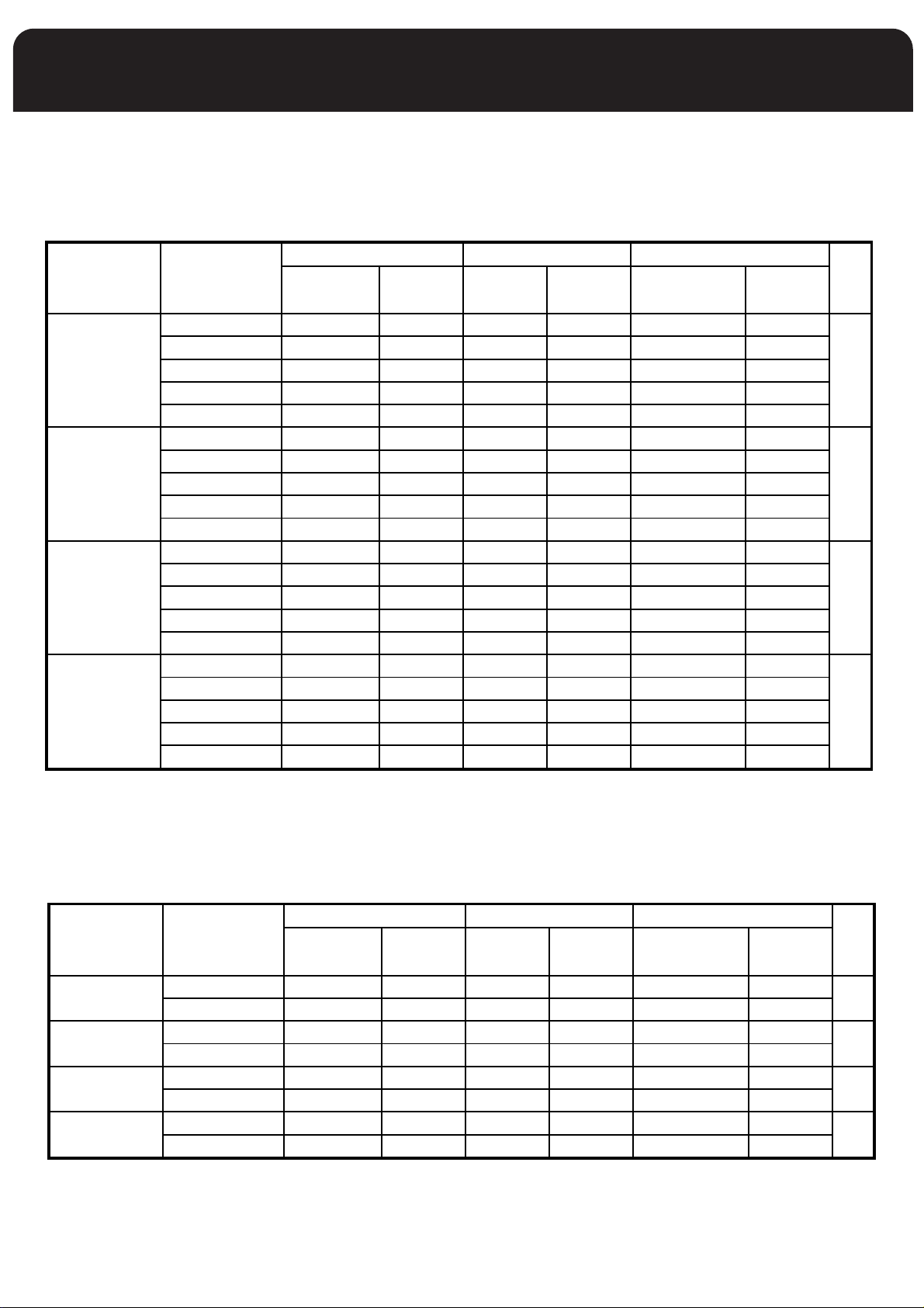
For USA
HIGH ALTITUDE SPECIFICATIONS
Rating Plate
High Fire
Input BTU/hr Altitude(ft) Input Output Input Output Natural Gas LP Gas
(BTU/hr)
0-2000 54000 51300 35100 33350 1.95mm 1.20mm
2000-3000 47520 45144 30888 29344 1.90mm 1.15mm
54,000 3000-4000 45360 43092 29484 28010 1.90mm 1.10mm 3
4000-5000 43200 41040 28080 26676 1.85mm 1.10mm
5000-6000 41040 38988 26676 25342 1.85mm 1.10mm
0-2000 72000 68400 46800 44460 1.95mm 1.20mm
2000-3000 63360 60192 41184 39125 1.90mm 1.15mm
72,000 3000-4000 60480 57456 39312 37346 1.90mm 1.10mm 4
4000-5000 57600 54720 37440 35568 1.85mm 1.10mm
5000-6000 54720 51984 35568 33790 1.85mm 1.10mm
0-2000 90000 85500 58500 55600 1.95mm 1.20mm
2000-3000 79200 75240 51480 48906 1.90mm 1.15mm
90,000 3000-4000 75600 71820 49140 46683 1.90mm 1.10mm 5
4000-5000 72000 68400 46800 44460 1.85mm 1.10mm
5000-6000 68400 64980 44460 42237 1.85mm 1.10mm
0-2000 108000 102600 70200 66690 1.95mm 1.20mm
2000-3000 95040 90288 61776 58687 1.90mm 1.15mm
108,000 3000-4000 90720 86184 58968 56020 1.90mm 1.10mm 6
4000-5000 86400 82080 56160 53352 1.85mm 1.10mm
5000-6000 82080 77976 53352 50684 1.85mm 1.10mm
(BTU/hr)
*MANIFOLD PRESSURE NATURAL GAS=3.5 INWC
**MANIFOLD PRESSURE L.P. GAS=10.5 INWC
Low Fire Orifice
(BTU/hr)
(BTU/hr)
(mm)* (mm)**
Qty
For- CANADA
HIGH ALTITUDE SPECIFICATIONS
Rating Plate
Input BTU/hr Altitude(ft) Input Output Input Output Natural Gas LP Gas
54,000
72,000
90,000 5
108,000
0-2000 54000 51300 35100 33350 1.95mm 1.20mm
2001-4500 48600 46170 31590 30011 1.90mm 1.15mm
0-2000 72000 68400 46800 44460 1.95mm 1.20mm
2001-4500 64800 61560 42120 40014 1.90mm 1.15mm
0-2000 90000 85500 58500 55560 1.95mm 1.20mm
2001-4500 81000 76950 52650 50018 1.90mm 1.15mm
0-2000 108000 102600 70200 66690 1.95mm 1.20mm
2001-4500 97200 92340 63180 60021 1.90mm 1.15mm
*MANIFOLD PRESSURE NATURAL GAS=3.5 INWC
**MANIFOLD PRESSURE L.P. GAS=10.5 INWC
High Fire Low Fire Orifice
(BTU/hr)
(BTU/hr)
(BTU/hr)
30
(BTU/hr)
(mm)* (mm)**
Qty
3
4
6

SETTING THE MANIFOLD (Outlet) GAS PRESSURE
(F92-1003 36G Valve Pressure Check Kit)
The manifold outlet pressure is specified on the rating
plate.
1. Shut off the gas upstream of valve and move valve
switch to OFF.
. Using the 3/32 inch hex wrench that is included in the
2
valve pressure check kit, rotate outlet pressure tap
screw one revolution counter-clockwise.
. Attach the 5/16 inch hose that is included in the valve
3
pre check kit to the outlet pressure boss of the valve.
Hose should overlap boss 3/8 inch.
4. Connect 5/16 inch side of connector that is included in
the valve pressure check kit to the hose on outlet boss.
Connect 1/4 inch side of connector to manometer hose.
5. Turn on gas supply to valve and move valve switch to
the ON position.
6. Turn on furnace. For the two stage valve the low rate
must be adjusted first and then the high rate. This can
be done by wiring the Thermostat so that only low fire
runs. Turn off the 1-stage T-stat mode on the control
board if set!
Remove regulator cover screw from the high or low
outlet pressure regulator adjust tower and turn
screw clockwise to increase pressure, or counterclock
wise decrease pressure. Always adjust regulator
as specified on the furnace rating label.
Natural Gas: Low outlet pressure is limited to 1 to 4”
W.C. range and high outlet pressure 2 to 5” W C range.
The valve cannot be adjusted outside this range and
the high outlet pressure setting must always be set at
least 1” above the low outlet pressure setting.
LP Gas: Low outlet pressure is limited to 6 to 10” W.C.
range and high outlet pressure in the 8 to 12” W.C.
range. The valve cannot be adjusted outside this range
and the high outlet pressure setting must always be set
at least 2” above the low outlet pressure setting.
7. Using a leak detection solution check for leaks at hose
connections.
DANGER
SHUT OFF GAS AND FIX LEAKS IMMEDIA
PROCEEDING.
8. Read manometer. This reading is the system
outlet/supply pressure.
9. Follow manufacturer’s instructions to adjust
outlet/supply pressure, if necessary.
Shut-off gas supply upstream of valve and move the
10.
valve switch to the OFF position.
11. Remove manometer and hose from outlet boss.
TELY BEFORE
12. Turn outlet pressure tap screw clockwise to seal the
pressure point using the supplied hex wrench. Tighten
to 13 in-lbs. minimum. Return all pressure regulator
caps.
13. Turn on gas supply to valve and move valve switch to
the ON position.
14. Turn on furnace following manufacturer instructions.
15. Using leak detection solution check for leaks at outlet
ressure tap. Shut off gas and fix all leaks immediately
p
before proceeding.
If problems were encountered with obtaining enough
pressure on the manifold, first examine the gas piping
ystem to ensure that it is correctly sized. Pipe sizing is
s
specified in ANSI Z223.1/ NFPA 54 in the U.S., or the B148
Natural Gas and Propane Installation Code in Canada.
SETTING THE SUPPLY GAS PRESSURE
(F92-1003 36G Valve Pressure Check Kit)
1. Back inlet pressure test screw (inlet/outlet pressure
boss) out one turn (counterclockwise, not more than
one turn) with a 3/32 inch Allen wrench.
2. Attach a hose and manometer to the inlet pressure boss
of the valve. The manometer should be capable of
reading 0 -15 inches water column.
3. Turn on the gas supply and electrical power to the
furnace.
4. Start the furnace, and any other gas burning
appliances on the same gas piping system.
5. Note the gas inlet pressure. It should be: Natural Gas: 5
to 10.5 inches water column L.P. Gas: 11 to 13 inches
water column.
6. If working on a natural gas system, contact the gas
utility. They may insist on any service regulator
adjustments being made by their own staff.
7. Adjustments are made in a similar fashion as the gas
valve regulator. Turn the adjustment screw clockwise to
increase manifold pressure, or counter clockwise to
reduce manifold pressure. When the correct pressure
has been established, securely replace the service
regulator protective screw cap.
8. Shut off the gas at the manual valve and remove
manometer hose from inlet pressure boss.
DANGER
A TRAINED, QUALIFIED TECHNICIAN MUST DO ALL
REGULA
OR ADJUSTMENTS CAN RESULT IN FIRE OR EXPLOSION
CAUSING PROPERTY DAMAGE, SEVERE PERSONAL INJURY
OR LOSS OF LIFE.
In some circumstances, high inlet pressure can be remedied
with the use of an inline appliance regulator
appliance regulator is used, ensure that it has the capacity to
adequately handle the gas volume required by the furnace
and any other appliances receiving gas from the header
serving the furnace.
TOR ADJUSTMENTS. IMPROPER MODIFICATIONS
. If an inline
31
ELECTRICAL SPECIFICATIONS
Before proceeding with the electrical connections, ensure
that the available electrical supply is compatible with the
voltage, frequency, and phase listed on the appliance rating
late.
p
All furnaces are rated 120 VAC, 60 Hz, 1 phase. The
amperage rating is indicated on the furnace rating plate.
Each furnace requires a dedicated overcurrent device either
a circuit breaker or a Type D, time delay fuse. It is
permissible to connect furnace accessories such as
humidifier transformers, condensate pumps and electronic
air cleaners. If adding accessory equipment to the furnace
circuit, ensure that the combined amperages listed on the
appliance rating plates do not exceed the rating of the over
current device.
IMPORTANT
USE COPPER CONDUCTORS ONLY
If the junction box must be moved to the right hand side:
1. Unfasten the junction box from the left hand side.
. Remove the right side panel knockout.
2
3. Remove the junction box cover hook screw and reinstall
t on the opposite side of the box.
i
4. Fasten the junction box to the right hand panel.
IMPORTANT
L1 (hot) and L2 (Neutral) polarity must be observed
when making field connections to the furnace. The
ignition control may not sense flame if L1 and L2 are
reversed. The ground is also essential.
DANGER
SHUT OFF ELECTRICAL POWER AT THE FUSE BOX OR
SERVICE PANEL BEFORE MAKING ANY ELECTRICAL
CONNECTIONS. FAILURE TO DO SO CAN CAUSE
ELECTRICAL SHOCK RESULTING IN PERSONAL INJURY OR
LOSS OF LIFE.
DANGER
THE FURNACE CABINET MUST HAVE AN
UNINTERRUPTED GROUND.
A GROUND WIRE IS PROVIDED IN THE ELECTRICAL
JUNCTION BOX.
DO NOT USE GAS PIPING AS A GROUND.
FAILING TO GROUND THE FURNACE PROPERLY CAN
RESULT IN ELECTRIC SHOCK RESULTING IN PERSONAL
INJURY OR DEATH.
In the United States, all electrical work must be in
accordance with the latest edition of the National Electrical
Code, ANSI / NFPA 70, in Canada, all electrical work must be
in accordance with the latest edition of CSA-C22.1, Canadian
Electrical Code Part 1, and any applicable local code.
Although a suitably located circuit breaker may serve as a
service switch, a separate service switch is recommended.
A separate service switch is necessary if the circuit breaker is
in a location where accessing it would require getting close
to the furnace, or if the furnace is located between the main
electrical panel and the entry to the furnace room. The
furnace switch (service switch) should be clearly labeled and
installed in a location where it is not likely to be mistaken as
being a light switch or similar control.
Furnace Connection
: The furnace is shipped fully wired except for the
120V
connections to the house wiring. The furnace power
connections are made in a junction box inside the blower
compartment. The junction box is factory installed on the
left hand side; however, it may be moved to the right hand
side. The junction box contains a BLACK wire to be
connected with L1 (hot), a WHITE wire to be connected with
L2, the Neutral, and a GREEN wire to be connected to the
ground.
IMPORTANT
The furnace shall be installed so the electrical
components are protected from water.
WARNING
THIS FURNACE IS EQUIPPED WITH A BLOWER DOOR
SAFETY SWITCH. DO NOT DISABLE THIS SWITCH.
FAILURE TO FOLLOW THIS WARNING CAN RESULT IN
ELECTRICAL SHOCK, PERSONAL INJURY, OR LOSS OF LIFE.
CAUTION
ELECTRICAL WIRING AND COMPONENTS MUST BE
PROTECTED FROM MOISTURE, INCLUDING WATER AND
CONDENSATE.
Low Voltage Wiring
The low voltage terminals are located on the control board
mounted to the blower assembly; see Figure 15 on page 37.
The furnace is prewired for air conditioning. Insert the
thermostat and air conditioner contactor low voltage
wiring through the bushing provided in the side panel.
Route the control wiring through the blower compartment
to the 24 volt terminal screws.
Thermostat
The room thermostat must be compatible with the
integrated control in the furnace. Electromechanical
thermostats should be rated 30 V / 1.5 amps.
Most electronic or microprocessor based thermostats except
those with "current robbing" circuits should work
satisfactorily
manufacturer for technical and installation details.
Most compatibility problems can be overcome by the use of
an isolation relay
24-volt coil. The switch ratings should be a minimum of 0.5
amps; see figure on next page.
The thermostat and control wiring should be a minimum of
18 AWG copper. Excessive lengths of wire may result in
enough voltage drop to impair the proper functioning of
the furnace. For thermostat wires in excess of 25 feet, use
WG; 50 feet, use 14 AWG.
16 A
. Consult the instructions of the thermostat
. The isolation relay should be SPST with a
32
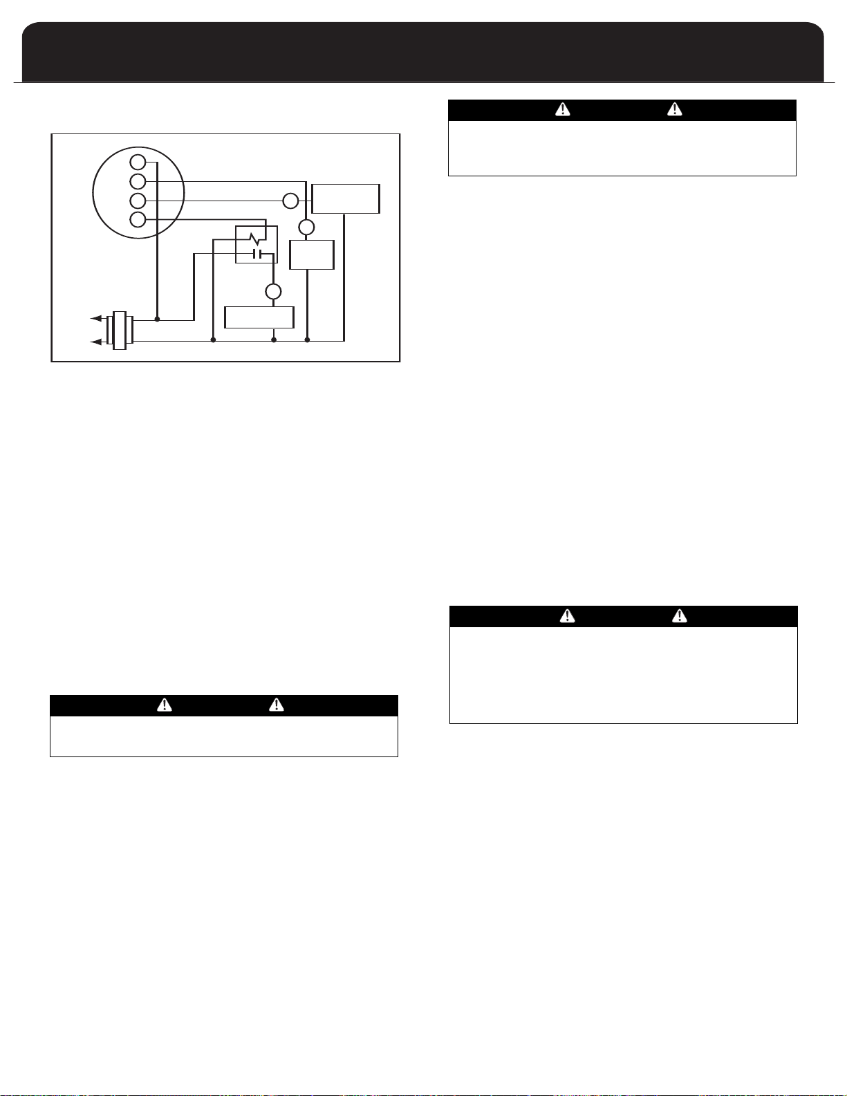
THERMOSTAT
COOLING
CONTAC TOR
FAN
RELAY
HEATING RELAY
24V
115V
R
G
Y
W
Y
G
W
ISOLATION RELAY
THERMOSTAT LOCATION
The thermostat should be located approximately 5 feet above
the floor, on an inside wall where there is good natural air
circulation, and where the thermostat will be exposed to
average room temperatures. Avoid locations where the
thermostat will be exposed to cold drafts, heat from nearby
lamps or appliances, exposure to sunlight, heat from inside
wall stacks, etc.
THERMOSTAT HEAT ANTICIPATOR SETTING: 0.45 AMP (WhiteRodgers) See page 39 for information on connecting optional
accessories such as electronic air cleaners and power
humidifiers.
ELECTRICAL WIRING AND COMPONENTS MUST BE PROTECTED
FROM MOISTURE, INCLUDING WATER AND CONDENSATE.
DEHUMIDIFICATION OPTION
The controller has a dehumidification option. When high
humidity is sensed (requires a 24 volt Humidistat that opens on
high humidity) the air flow is reduced to increase condensing.
To activate, the jumper labeled “DEHUM” must be moved to
the “yes” position.
AIRFLOW
ALL CONTROLLER JUMPER CHANGES MUST BE MADE
WITH POWER DISCONNECTED TO THE FURNACE.
The ECM TM blower is preprogrammed from the factory to
hold constant flow. (Replacement motors must have the
correct part number and can only be ordered from the furnace
manufacturer.) Changing the Taps allow adjustment for various
size A/C tonnage as well as an adjustment in flow. Changing
the Heating Tap changes the Temperature Rise in about 5 F
increments. The Taps are in a row of jumper labeled “COOL”,
“HEAT” and “ADJUST”.
Table on page 36 shows the recommended taps for heating
and cooling speed. Heating Tap A is factory set for heating speed.
If the Adjust Tap is used for cooling then the heating speed
should be adjusted to counter the ef
tap. Rule of thumb: The Heating Tap will be the same as the
“ADJUST” Tap.
ARNING
W
fects of the adjustment
WARNING
Make adjustments to the controller with the electrical
power off.
START UP PROCEDURES
This furnace is equipped with a hot surface ignition (HSI)
device. Each time that the room thermostat calls for heat,
the HSI lights the main burners directly. See the lighting
instructions on the furnace.
To Start The Furnace:
1. Remove the burner compartment access door.
2. Shut off the electrical power to the furnace and set the
room thermostat to its lowest setting.
3. Ensure that the ignition system control switch on the
gas valve is in the “ON” position.
Replace the burner compartment access door
4.
.
5. Restore electrical power to the furnace.
6. Set the room thermostat to a point above room
temperature to light the furnace.
7. After the burners are lit, set the room thermostat to the
desired temperature.
To Shut Down The Furnace:
1. Set the room thermostat to its lowest setting.
2. Remove the burner compartment access door.
The ignition system control switch on the gas valve may
3.
be switched to the “OFF” position.
4. The furnace appliance shutoff valve may be closed if
desired.
WARNINGi
SHOULD OVER HEATING OCCUR, OR THE GAS BURNERS
FAIL TO SHUT OFF, CLOSE THE MANUAL GAS VALVE FOR
THE FURNACE BEFORE SHUTTING OFF THE ELECTRICAL
POWER TO THE FURNACE. FAILURE TO DO SO CAN
CAUSE AN EXPLOSION OR FIRE RESULTING IN PROPERTY
DAMAGE, PERSONAL INJURY OR LOSS OF LIFE.
Sequence of Operation
1. Room temperature drops causing the room thermostat
heating W1 contacts to close.
2. The inducer blower is energized at high speed and the
control waits for the low pressure switch contacts to
close.
3. Once the low pressure switch contacts close, a 15second pre-purge is initiated. Then the inducer
changes to low speed and the 120VAC ignitor is
powered.
4. After the prepurge period, the hot surface ignitor
heats up; 10 seconds on a first try, maximum 14 seconds
on a subsequent retry.
33

6. The circulating fan begins 30 seconds after flame is
sensed.
7. Furnace continues to run in this state until a call for
second stage heat (W1 and W2) after a call for first
stage heat will energize the inducer at high speed and
the circulator high heat. The second stage pressure
switch contacts will close and energize the second
stage gas valve (high fire).
8. When the second stage of the thermostat is satisfied,
the inducer motor is reduced to low speed and the
second stage gas valve is de-energized. When the first
stage of the thermostat is satisfied, the first stage gas
valve is de-energized and the HEA
T delay-to-fan-of
begins timing.
With the thermostat heating contacts open, the burner
flames extinguish immediately, the induced blower
stops after a 5 second postpurge period. The pressure
switch contacts open.
9. The circulating fan continues to run until timed out,
depending on the program settings.
Sequence if the fur
nace does not light up or
detect flame:
1. If flame is not detected during the trial-for-ignition
period, the gas valve is de-energized, the ignitor is
turned of
sequence.
The "retry" sequence provides a 30-second wait with
the inducer interpurge following an unsuccessful
ignition attempt (flame not detected). After this wait,
the ignition attempt is restarted. Two retries will be
attempted before the control goes into system lockout.
If the flame is established for more than ten seconds
after ignition, the controller will clear the ignition
attempt (or retry) counter. If flame is lost after 10
seconds, the control will restart the ignition sequence.
A momentary loss of gas supply, flame blowout, or a
shorted or open condition in the flame probe circuit
will be sensed within 2 seconds. The gas valve will
de-energize and the control will restart the ignition
sequence. Recycles will begin and the burner will
perate normally if the gas supply returns, of the fault
o
ondition is corrected, before the last ignition attempt.
c
Otherwise, the control will go into system lockout.
If the control has gone into system lockout, it may be
possible to reset the control by a momentary power
interruption of 10 seconds or longer.
Room temperature drops causing the room thermostat
heating contacts to close.
2. If pressure switch contacts are closed; and have failed
to open since the last cycle, all subsequent steps will
fail to occur.
3. The induced blower begins a prepurge cycle of 15
seconds.
4. The pressure switch contacts close. The pressure switch
contacts must close within 30 seconds. If they fail to do
so, the induced blower will shut off for a five minute
period, then the sequence will begin again at Step 2.
f, and the control goes into the "retry"
5. After the prepurge period, and after pressure switch
contacts have closed, the hot surface igniter heats up;
5 seconds on a first try, 10 seconds on a subsequent
retry.
Additional information is available in the
Troubleshooting section that starts on page 38 of this
manual.
Checking Furnace Input
• The natural gas supply pressure should be a maximum of
10.5 inches w.c. and minimum of 5 inches w.c.
f
• The burner manifold pressure is normally set to 3.5 inches
for high fire input, 1.8 inches for low fire input
• The input rating of the furnace is based on 1075 BTU/ ft
gas with a specific gravity of 0.60
Since heating values for the gas vary geographically, the
actual furnace input and output will vary accordingly.
2
For example, natural gas with a 1000 BTU/ ft
will reduce the input to 93% of the rated input. Natural gas
with a 1100 BTU/ ft
2
heating value will increase the input to
heating value
approximately 103% of the rated input. This is not usually a
problem; however, adjustments to compensate for this can
be made by minor adjustments to the burner manifold
pressure or by changing the burner orifice size.
In the previous example where the heating value of the gas
is 1100 BTU/ ft
2
, the burner manifold pressure can be
reduced .3” w.c. to 3.4’ w.c. which is within the ±0.30 inches
.c. specification to bring the input into compliance. Refer
w
also to
Setting the Gas Pressure section, and contact the fuel
supplier for specific gas heating content values.
If using a gas meter to check the furnace input, be sure that
all gas fired appliances other than the furnace are off
during the test.
Any adjustments to the burner manifold pressure should be
carried out with the use of a manometer or calibrated
magnehelic gauge. Do not adjust the gas valve pressure
regulator more than ± 0.30 inches water column.
(See next page for formula.)
3
34
Heating Value of Gas X 3000
T
I
nput =
Heating Value of Gas X 3000
Time in Sec. or 1 cu. ft.
Input =
Bonnet Output
1.085 x T
Airflow (CFM) =
The formula for determining the furnace input via the gas A temperature rise within 35-65 degrees F is acceptable
meter test dial is:
when the furnace is operating with both stages of heat
on. If a higher temperature rise is desired, refer to the dip
switch settings for “Heating”. This can be adjusted to
ime in Sec. for 1 cu. ft.
here:
W
Input is expressed in BTU/Hr.
Heating value of the gas is expressed in BTU/ ft
3
Time means time required for the test dial to indicate 1 ft3/sec.
f using a gas meter with SI (metric) units:
I
3
1 ft
= 0.0283 m
1 m3= 35.315 ft
0.01 m3= 0.3531 ft
0.5 m3= 1.766 ft
3
3
3
3
Nominal-Plus to reduce the air temperature rise or
ominal-minus to increase the air temperature rise.
N
AIRFLOW
or proper furnace operation, airflow over the heat
F
xchanger is of utmost importance. Insufficient airflow
e
accelerates metal fatigue and failure in the heat exchanger
and excessive airflow promotes accelerated corrosion of the
heat exchanger.
IMPORTANT: Do not bypass this step of the start up
procedures.
Calculating Airflow
There are circumstances where it may be desirable to
know the airflow delivery through the duct system, such as
when estimating the amount of airflow available for air
IMPORTANT: NEVER ADJUST THE INPUT OF THE FURNACE
TO EXCEED THE INPUT SHOWN ON THE RATING PLATE.
conditioning. This can be done by direct measurement
with electronic or sloped manometers and velometers, or
by using the formula below.
Circulating Air Blower And Temperature Rise Check
The FV95A series 2-stage gas furnace is supplied with a
variable speed circulation air blower motor that will supply
a constant airflow when operated within the external static pressure limits of the unit. One of the benefits of a variable speed circulation air blower is soft starting and stopping. The motor will ramp up to normal operating speed
gradually. This will minimize noise and increase comfort by
eliminating the initial blasts of cooler air encountered with
constant speed motors. At the end of a heating or cooling
cycle, the variable speed motor will slowly ramp down
after the blower off delay timer expires. If the fan is set to
operate as a continuous blower, the motor will slowly ramp
down to the airflow set for that mode.
Temperature Rise Check
When the duct system is complete and the air filters are in
place, determine the air temperature rise of the furnace.
Insert a duct thermometer in the supply air duct. The thermometer should be placed as close as practical to the furnace, but out of the “line of sight” of the heat exchanger
so to prevent a false reading due to radiated heat. Ensure
that the thermometer is within the duct air-stream. Avoid
locations such as the inside radius of an elbow
Insert a duct thermometer into the return duct as close to
the furnace as possible. Ensure that the thermometer location will be unaffected by humidifier bypass ducts, etc.
Choose a location that ensures the thermometer will be
within the air-stream of the duct. Operate the furnace long
enough to obtain a steady state condition.
When the two thermometers have stabilized, compare the
two readings. Subtract the return air duct temperature
from the supply air duct temperature. This difference is
the temperature rise.
, etc.
Where:
CFM is airflow in cubic feet per minute
∆T is the temperature rise
Bonnet output is the furnace output capacity from the
rating plate.
NOTE: The bonnet output will vary directly with the input.
If the actual input is below the stated input, the output will
be reduced in the same ratio.
Adjusting Dip Switches
If the blower speeds require adjusting, follow these steps:
WARNING
DISCONNECT THE ELECTRICAL SUPPLY TO THE FURNACE
BEFORE ATTEMPTING TO CHANGE THE BLOWER SPEED.
AILURE TO DO SO COULD RESULT IN ELECTRICAL SHOCK
F
RESULTING IN PERSONAL INJURY OR LOSS OF LIFE.
Remove the blower compartment door.
1.
2. Refer to the tables next page for adjusting DIP
switches/jumpers and select the appropriate settings
3. DIP switches or jumpers are found on the integrated
furnace control board.
NOTE: some integrated furnace controls are equipped
with jumpers for blower adjustments. Please reference
“Letter” on adjustment table and control board when
making adjustment.
4. Re-install the blower compartment door.
5. Upon completion, recheck the furnace temperature rise
to ensure that the desired condition exists.
35

Rating Plate
Input BTU/hr
Rating Plate
Input BTU/hr
Switch
Description
Cool
Jumper
AC Tonnage
Rise
Heating
Jumper
54,000
72,000
90,000
108,000
54,000
72,000
90,000
108,000
DIP Switch Configurations
To obtain the correct airflow for the cooling mode, please refer to the table above.
Note the position of the delay tap.
It is recommended that the heating airflow be set for the Nominal-Plus setting when the furnace is
matched for this cooling capacity.
Furnace is set at the factory for maximum cooling capacity and DIP switches must be field configured
to match the cooling system.
3.0
2.5
2.0
1.5
A
B
C
D
A
B
C
D
A
B
C
D
A
B
C
D
2.5
2.0
1.5
1.0
Cool
3.0
2.0
2.5
1.5
Cool
5.0
3.5
2.5
1.5
4.0
3.0
2.0
1.0
Cool
5.0
3.5
2.5
1.5
4.0
3.0
2.0
1.0
Cool
A
B
C
D
A
B
C
D
A
B
C
D
A
B
C
D
50
45
55
60
50
45
55
60
50
45
55
60
50
45
55
60
ADJUST
(NORM)
ADJUST
( - )
3.5
1.0 1.0
3.0
36
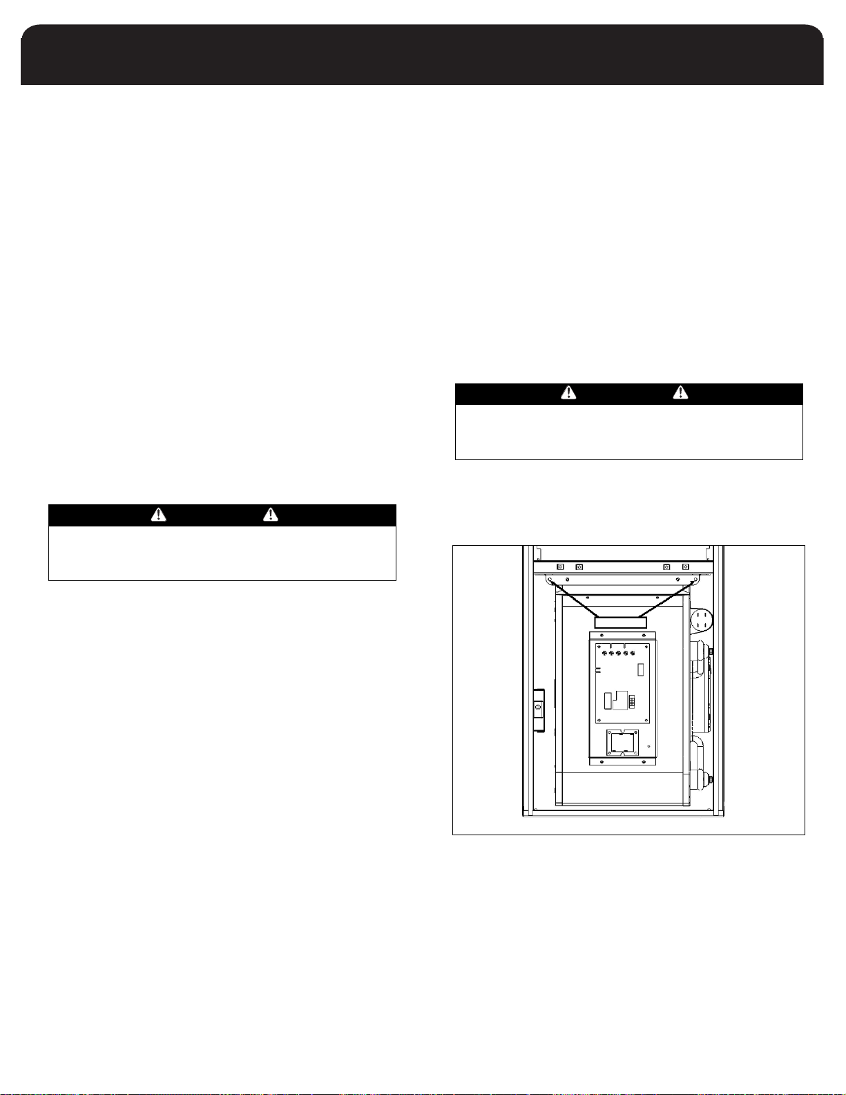
All Delay
5
5
Off
6
On
5
On
6
On
5
On
T
No
delayNodelay
1
30
30
Off
0
On
C
B
D
S4
6On
S
180
30
Off
On
ADJUSTING BLOWER SPEEDS
Cooling Mode
The unit is factory set to provide the highest airflow.
djustments can be made to match the furnace with a small-
A
er cooling coil by changing the DIP switch or jumper settings,
located on the integrated ignition control board. Refer to
the Cooling DIP switch or jumper settings table for instructions
on how to set the switches. Please note that if the furnace is
to be matched to the lowest airflow for cooling, the "Adjust"
DIP switches or jumper setting must be set to the decreased
setting. When using this setting, it is recommended that the
Heating DIP switches or jumper setting be set for NominalPlus.
Heating Mode
The unit is set from the factory to operate at the center of
the temperature rise range. For this model furnace, the air
temperature rise is between 35 and 65 degrees F. Heating
airflow can be increased or decreased by changing the
heating mode DIP switches or jumpers, located on the integrated ignition control board, to the Nominal-plus/minus
settings. Please note that Nominal-plus will decrease the
air temperature rise and the Nominal-minus will increase
the air temperature rise. At the end of a call for heat, the
main blower has a fixed off delay at a reduced airflow to
remove residual heat from the heat exchanger.
How To Install The Blower
1. Place blower into blower compartment.
2. Keep blower assembly tight to top of blower
compartment. Line up blower assembly to slide into
blower rails. Push blower assembly towards back of
urnace ensuring blower assembly is correctly placed in
blower rails. Insert blower shroud on the front of the
blower housing. Insert blower housing bolts and
tighten.
3. Connect thermostat wiring to the integrated furnace
control.
4. Connect L1, Neutral and Ground connections between
the integrated furnace control and the furnace
electrical connection junction box.
5. Connect 12 pin male molex connector to female
connection point, and ground connection to the
integrated furnace control.
6. Turn on power to the furnace.
WARNING
Ensure that there is a drip bend in the connect wires to
the blower motor to prevent condensate from following
the wire into the connector.
WARNING
Make adjustments to the controller with the electrical
power off.
How To Remove The Blower
1. Disconnect power from furnace.
2. Remove thermostat wiring from the integrated furnace
control.
3. Remove L1, Neutral and Ground connections between
the integrated furnace control and the Furnace
electrical connection junction box.
4. Remove 12 pin male molex connector from female
connection point, and ground connection from
integrated furnace control.
5. Unscrew 2 blower housing bolts located in the front
blower shroud as indicated in figure 15 (right). Remove
front blower shroud from furnace.
6. Slide blower assembly towards front of furnace. Blower
is mounted on rail system, and will slide forward about
10 inches before blower is clear of rails.
FIGURE 15
BLOWER BOLTS
Bolts
37

TABLE 8
5
On
6
On
5
On
T
30
30
Off
0
On
C
B
D
6
On
S
180
30
Off
On
MAINTENANCE
WARNING
DISCONNECT THE ELECTRICAL POWER SUPPLY TO THE
FURNACE BEFORE ATTEMPTING ANY MAINTENANCE.
FAILURE TO DO SO CAN CAUSE ELECTRICAL SHOCK
RESULTING IN PERSONAL INJURY OR LOSS OF LIFE.
ir Filter
A
The filter should be inspected frequently and cleaned as
necessary. We recommend a monthly inspection at first,
erhaps coinciding with the arrival of the monthly fuel bill
p
as a reminder. The frequency may be increased or decreased
depending on experience and conditions.
CAUTION
DO NOT OPERATE THE FURNACE WITHOUT AN AIR FILTER.
Lubrication
Both the induced draft blower motor and circulating fan
motor are ball bearing type motors. Neither requires
routine lubrication.
The motor bearings were prelubricated by the motor
manufacturer. Do not attempt to lubricate them. Excess
lubrication will void the warranty, shorten the service
life of the motors, and will attract the buildup of dust
and dirt.
The induced blower motor and circulating fan motor must
be cleaned on a periodic basis by a qualified service
technician. Dust buildup in the ventilation ports of the motor
will cause the motor to not dissipate heat properly resulting
in reduced service life.
Vent Connector
The exhaust venting between the furnace vent box and
chimney should be inspected periodically for sags, pitting,
evidence of leakage etc. If any of these conditions exist,
contact your installation contractor, service agency or fuel
supplier.
IMPORTANT
WARNING
HOLES IN THE EXHAUST PIPING OR FURNACE HEAT
EXCHANGER CAN ALLOW TOXIC FUMES TO ENTER THE
HOME AND CIRCULATE THROUGH THE DUCT SYSTEM
RESULTING IN CARBON MONOXIDE POISONING OR
DEATH. IF LEAKS ARE FOUND IN THE FURNACE HEAT
EXCHANGER, IT MUST BE REPLACED.
Operating Tips
1. Clean air filters maximize efficiency and reduce
heating costs.
During the heating season, keep windows and doors
2.
closed to reduce the heating load on the system.
3.
A
void excessive use of kitchen exhaust hoods and other
exhaust fans to reduce the heating load on the system.
4. Arrange the furniture and drapes so that the supply air
registers and return air grilles are unobstructed.
5. If you have a perimeter duct system, ideally, the warm
air should bathe the cold exterior walls. Avoid the use
of plastic deflectors on the supply air registers that
tend to short circuit the warm air straight into the
return air grilles. These deflectors are often the cause
of cool draughts across the floor
.
6. Avoid placing heat producing appliances such as
televisions, radios, lamps, etc. in a location to influence
the thermostat.
7. Keep combustible articles at least 3 feet away from the
furnace. Do not block access for servicing the furnace.
Do not use the vent connector as a hanger for clothes
or anything else.
8. Never attempt to operate the furnace without the
blower door in place.
ANNUAL INSPECTION / SERVICE
A qualified installation contractor, service agency or fuel
supplier must inspect the furnace annually.
Your annual inspection will normally cover the following:
Heat Exchanger
The heat exchanger should be inspected for corrosion. The
flue passages (heat exchanger tubes) should be free of scale
or excessive corrosion. Observe the burner flames. If there
appears to be flame distortion, check venting for blockage.
Also check for signs of inadequate combustion air supply. If
flame distortion continues after eliminating the blockage in
the venting as the cause, it may be necessary to replace the
tubular heat exchanger. The tubular heat exchanger cannot
be field cleaned. If the tubular heat exchanger is blocked by
soot or excess scale, replace it. Check NOX baffles (installed
in heat exchanger tubes) for any distortion. If distorted,
replace NOX baffles.
Burners
The burners should be inspected to ensure that they are free
of deterioration, dust and debris, and properly aligned with
the heat exchanger. In most cases, a simple vacuuming with
a brush attachment will adequately clean the burner
assembly and burner compartment.
CAUTION
BE CAREFUL WHEN WORKING ON THE BURNER
ASSEMBLY. THE HOT SURFACE IGNITER IS FRAGILE AND
CAN BREAK EASILY.
The flame sensor should be inspected and cleaned with fine
steel wool or Scotch-Brite™ scrubbing pad. The wiring
connection should be checked to ensure that it is tight and
corrosion free.
IMPORTANT
This is a critical connection. Small amounts of corrosion
can significantly increase the internal resistance of the
connection. A relatively small increase in resistance can
result in a large decrease in flame signal.
Induced Blower
The induced blower motor should be inspected and cleaned
if necessary. Clear any dust buildup from the ventilation
ports.
Circulating Fan
The condition of the circulating fan should be checked to
ensure that it is free of excessive dust buildup, debris, etc.
The mechanical fasteners should be inspected and checked
for proper tightness and parts alignment. The motor
ventilation ports should be cleaned if necessary to prevent
restriction to cooling by air over the motor.
38
Electrical
WARNING
DISCONNECT THE ELECTRICAL POWER SUPPLY TO THE
FURNACE BEFORE ATTEMPTING THIS MAINTENANCE
PROCEDURE. FAILURE TO DO SO CAN CAUSE
LECTRICAL SHOCK RESULTING IN PERSONAL INJURY OR
E
OSS OF LIFE.
L
ll electrical connections should be examined to ensure that
A
they are tight and corrosion free. Repair any connections
that have become loose or corroded.
CAUTION
Label all wires prior to disconnection when servicing
controls. Wiring errors can cause improper and
dangerous operation.
Always verify proper operation after servicing.
Furnace Operation
The furnace should be cycled during the annual inspection
and servicing to:
1. Test all safety related controls.
2. Determine that the temperature rise falls within the
range shown on the appliance rating plate.
3. Ensure that the burner ignition is smooth and that the
flames are smooth soft blue, and not impinging on the
heat exchanger.
FIELD SUPPLIED AND INSTALLED OPTIONAL
ACCESSORIES
Electronic Air Cleaner
The integrated furnace control has provisions to supply
power and control an electronic air cleaner rated at 120vac,
1.0 amp max.
Line voltage for an electronic air cleaner may be picked up
from the "EAC-N". 120 volt power will be available at these
terminals whenever the circulating fan is operating in the
heating or cooling modes.
Humidifiers/ Electronic Air Cleaners
The integrated furnace control has provisions to supply
power and to control a line voltage humidifier or the
primary of a 120 / 24 volt humidifier step down transformer
rated at 120vac, 1.0 amp max.
Line voltage for a humidifier may be picked up from the
"HUM-H" terminal and from the "HUM-N" terminal. 120
volt power will be available at these terminals whenever
the circulating fan is operating in the heating mode.
IMPORTANT
All HUM (humidifier) and EAC (electronic air cleaner)
terminals are 120v. Do not directly connect 24v
equipment to them.
WARNING
ALL WIRING INSIDE THE FURNACE MUST HAVE A
MINIMUM TEMPERATURE RATING OF 105C.
Troubleshooting
Page 41, Table 9, Page 42, Table 10 and Figure (trouble shooting)
will aid in trouble shooting.
The controller ignites the furnace in low heat and high
inducer (only the low pressure switch is required to make)
and after a 60 second warm-up period adjusts either the gas
or inducer to heat demand. With the single stage
thermostat option, there is a selectable low heat period
before high heat. If there is a problem with high or low
eat the UTEC 1170-25 controller will attempt to continue
h
to supply heat in one of three alternate firing scenarios.
Scenario one:
• if, after the warm-up period and the low heat period with
a single stage thermostat, or with a two stage T-stat the
demand for heat is high and the high heat pressure switch
fails to make, the furnace will run in low gas and high
inducer until the high pressure switch makes.
The second scenario;
If the low heat fails after the warm-up period, the
controller will wait 3 minutes before ignition retrial and
then after the warm-up period go to high heat. Most likely
the failure of the low heat is temporary and may be due to
a combination of high wind and long vent length and low
voltage. If there is a blocked drain the furnace will not turn
the igniter or gas on. If there is an air trap in the heat
exchanger drain tube the furnace will cycle and flash code
for pressure switch failed to close.
The third scenario;
If the low heat fails after the warm-up period, and when
the next trial for high fails to make the high pressure
switch, the unit will stay in low heat and high inducer (as
long as the low pressure switch is made). If, during this
period, the high pressure switch makes, the gas valve will
switch to high. A loss of high pressure switch will force the
gas valve to low. If there is ice in the vent the continuous
heat should free it. Note: When the inducer is in high and
,
the gas low the flame noise sounds deceptively like high
heat.
The fourth scenario:
If there is a demand for high heat (low heat firing period is
finished) and during the trial for ignition the high pressure
switch does not pull in the controller will continue in low
heat and make a retrial for high every 5 or 10 minutes.
IMPORTANT
All furnace and furnace accessory wiring shall conform
to the temperature limitations of 63
°F (35°C) rise.
39


TABLE 9
ED FLASH(ES)
L
Green Off
1 Red
2 Red
3 Red
4 Red
5 Red
6 Red
NDICATES (FEDDERS UTEC 1170-25 CONTROLLER)
I
Internal controller or Room Air Fan failure.
DO NOT operate on heat until Fan failure cleared.
Roll-out open. Cycle power to reset.
Flame sensed with gas valve de-energized.
Pressure switch(es) remains open. Combustion
Blower cycles until low pressure switch closes. If
running, high pressure switch is open.
Pressure switch(es) remains closed. Combustion
Blower will not operate until switch(es) opened.
Open high room air limit switch.
Room Air Fan failed or rollout switch(es) open.
System lockout reset by recycling power.
Caution: Do not run on heat until fan operational.
115 Volt AC power reversed or improper ground.
CHECK and REPAIR
1. Replace Integrated Furnace Control.
. Rollouts or Fan failure– see 5 Red
2
Flashes.
Mis-wiring is probable cause.
. Pressure switch failure.
1
2. Pressure switch tubing, and wiring.
3. Obstructions in air intake or exhaust
flue system that prevent proper
combustion air flow.
1. Pressure switch(es) failure.
2. Pressure switch(es) mis-wired or
jumpered.
Dirty filter or room air vents closed.
1. Wiring in good condition and securely
connected. Drip leg at Motor
connector.
2. Check Room Air Fan by running A/C or
Fan (not heat).
3. Blockage in heat exchanger or venting.
Line voltage polarity, and earth ground.
7 Red
8 Red
9 Red
10 Red
Low flame sense signal. 1 hour lockout.
Too many high air temperature limit trips. 1 hour
lockout.
Too many low pressure switch trips after ignition. 1
hour lockout
1 hour lockout. Reset by cycling power or
thermostat.
1. Flame at burner.
2. Dirty or cracked flame sensor.
See 4 Red Flashes
See 2 Red Flashes.
1. Gas supply off or at too low pressure.
Smell gas? Igniter failure.
2.
3. Earth grounded.
41
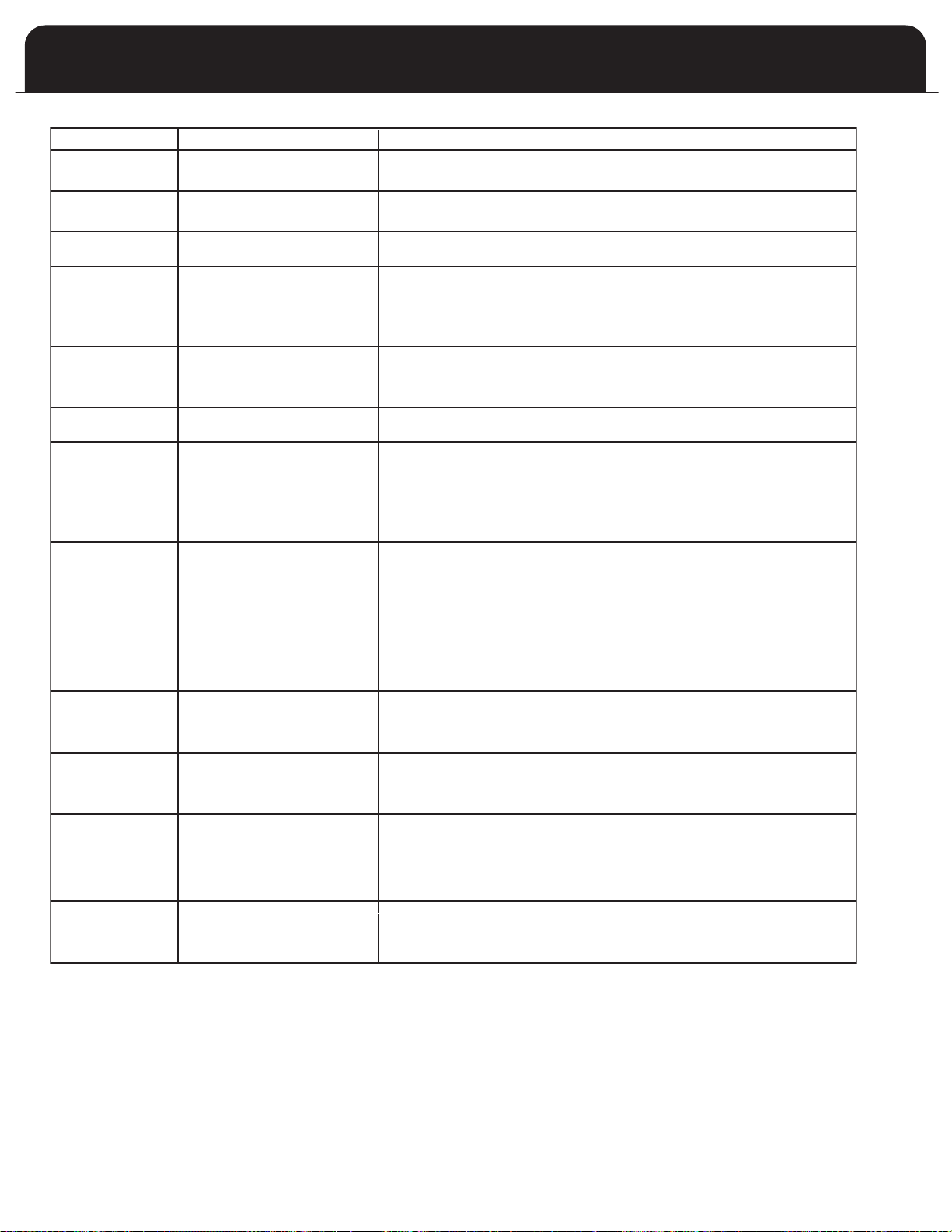
IF AND CHECK or REPAIR
Induced blower does
not energize
3 Flash code does not come on
1. Induced blower wiring.
2. Induced blower.
Induced blower does
not energize
3 Flash code does come on
1. Pressure switch stuck closed.
2. Pressure switch is mis-wired or jumpered.
Induced blower is
energized
2 Flash code does not come o n
Wait for the pre-purge to expire.
2 Flash code
comes on
Induced blower turns off
1. Pressure switch stuck in the open position.
2. Pressure switch, tubing and wiring.
3. Obstruction in furnace venting that is preventing proper combustion airflow.
Pre-purge time h as
expired
HSI element does not glow r ed
within 10 seconds.
1. Broken or damaged HSI element.
2. Broken or damaged HSI element leadwires.
HSI element i s glowing red.
No other visible control system
action
Wait for HSI element warm up time to expire.
HSI element warm u p
time has expired a nd
main valve has been
energized.
Main valve does not light within
trial for ignition period
1. Induced blower moving main burner gas away from the HSI element.
2. Inlet gas pressure too low for main burner ignition.
3. Input line voltage too low to heat HSI element.
4. HSI element incorrectly positioned.
5. Clogged or incorrect main burner orifice.
Main burner lights
within trial for ignition
period.
Main valve i s de-energized a t the
end of the trial for ignition period.
If main flame i s not sensed during
trial for ignition, system will shut o ff
HSI element and main gas flow,
then g o through another purge
period and initiate another ignition
trial. A total o f 4 ignition trials will
be attempted before the system
goes into lockout.
1.
Line voltage to L1 terminal of integrated furnace control must be
120 volts with reference to furncace chassis.
2. Furnace must be reliably connected to earth ground.
3. Induced blower moving main burner flame away from the flame sensor rod.
4. Inlet gas pressure too low for proper flame sensing.
5. Flame sensor rod contaminated or in incorrect position.
Main burner stays o n
after the end of t he
trial for ignition p eriod.
Circulating fan is not turned on after
30-second time delay.
1. Wiring between system control and integrated furnace control.
Proper operation of integrated furnace control.
Main burner goes o ut
before thermostat call
for heat ends.
4 Flash code comes on
1.
2.
Open high limit switch.
High limit wiring in good condition and securely connected.
Main burner goes o ut
before thermostat call
for heat ends.
4 Flash code does not come on
Green LED off
1.
Induced blower moving main burner flame away from flame sensor rod.
3.
Pressure switch has opened.
1.
2.
Open flame rollout switch
Rollout switch wiring in good condition
Broken or damaged blower
4.
Flame sensor rod ceramic or leadwire overheated.
Gas supply / flow reduced or interrupted.
5 Flash code comes
on.
TABLE 10 : GENERAL TROUBLESHOOTING INTEGRATED FAN CONTROL
2.
2.
3.
42

7+(&21752/3529,'(6$029$%/(-803(5726(/(&7%(7:((1$8720$7,&
67$*,1*0,187($1'0,187(67$*,1*
)$&725<'()$8/76(77,1*$8720$7,&67$*,1*86(:,7+7:267$*(
7+(50267$7
)256,1*/(67$*(7+(50267$7-803(51(('672%(6(7720,187(
250,187(67$*,1*
D-803(5$70,187(67$*,1*&21752/:,//$8720$7,&$//<67$57
+,*++($7$)7(50,187(62)&217,18286/2:+($723(5$7,21
E-803(5$70,187(67$*,1*&21752/:,//$8720$7,&$//<67$57
+,*++($7$)7(50,187(62)&217,18286/2:+($723(5$7,21
43

User’s Information Manual
TABLE OF CONTENTS
FURNACE COMPONENTS . . . . . . . . . . . . . . . . . .1
REGULATOR VENT . . . . . . . . . . . . . . . . . . . . . . .1
GENERAL SAFETY RULES . . . . . . . . . . . . . . . . . .1
FURNACE OPERATION INFORMATION
TO START THE FURNACE . . . . . . . . . . . . . .2
FURNACE SHUTDOWN PROCEDURE . . . . .2
MAINTENANCE
REPLACING AIR FILTER . . . . . . . . . . . . . . . .3
LUBRICATION . . . . . . . . . . . . . . . . . . . . . . .3
ROUTINE EXAMINATION . . . . . . . . . . . . . .3
FURNACE APPEARANCE . . . . . . . . . . . . . . .4
CLEANING . . . . . . . . . . . . . . . . . . . . . . . . . .3
. . . . . . . . . . . . . . . .
SEQUENCE OF OPERA
READ THESE INSTRUCTIONS THOROUGHL
ATTEMPTING TO OPERATE THIS FURNACE.
This furnace has been designed to deliver many years of
ficient, dependable service. With regular
ef
maintenance, some of which requires the attention of
a qualified installer
some of which you may do yourself, the furnace will
operate satisfactorily over many heating seasons.
Please read this manual to familiarize yourself with
safety procedures, operation, and routine maintenance
procedures.
TION
Y BEFORE
, service agency or gas supplier,
4
WARNING
WHAT TO DO IF YOU SMELL GAS:
• DO NOT TRY TO LIGHT ANY APPLIANCE
• DO NOT TOUCH ANY ELECTRICAL SWITCH; DO NOT
USE ANY PHONE IN YOUR BUILDING
• LEAVE THE BUILDING IMMEDIATELY
• IMMEDIATELY CALL YOUR GAS SUPPLIER FROM A
PHONE OUTSIDE THE BUILDING. FOLLOW THE GAS
SUPPLIER’S INSTRUCTIONS
• IF YOU CANNOT REACH YOUR GAS SUPPLIER, CALL
THE FIRE DEPARTMENT
• INSTALLATION AND SERVICE MUST BE PERFORMED BY
A QUALIFIED INSTALLER, SERVICE AGENCY OR THE
GAS SUPPLIER
DO NOT USE THIS FURNACE IF ANY PART HAS BEEN
UNDER WATER. A FLOOD DAMAGED FURNACE IS
EXTREMELY DANGEROUS. ATTEMPTS TO USE THE
FURNACE CAN RESULT IN FIRE OR EXPLOSION. A
QUALIFIED SERVICE AGENCY SHOULD BE CONTACTED
TO INSPECT THE FURNACE AND TO REPLACE ALL GAS
CONTROLS, CONTROL SYSTEM PARTS, ELECTRICAL PARTS
THAT HAVE BEEN WET OR THE FURNACE IF DEEMED
.
NECESSAR
DO NOT STORE OR USE GASOLINE OR OTHER
FLAMMABLE V
THIS OR ANY OTHER APPLIANCE.
Y
FIRE OR EXPLOSION HAZARD
APORS AND LIQUIDS IN THE VICINITY OF
FAILURE TO FOLLOW SAFETY WARNINGS EXACTLY
TH, OR
COULD RESULT IN SERIOUS INJURY
, DEA
PROPERTY DAMAGE.

FURNACE COMPONENTS
FIGURE 2
GAS REGULATOR VENT
FIGURE 1
F
URNACE COMPONENTS
REGULATOR VENT
Most natural gas systems and all LP gas systems have a
service regulator located near the point where the gas
piping enters the building. The propane tank will normally
have an additional first stage regulator located at the tank
outlet valve. All of these regulators (located outdoors) will
have a vent; see Fig. 2 (below).
Regulator vent
Keep free of ice, snow,
and debris
It is important for these vents to remain clear. Do not allow
moisture, which could freeze, to build up in the vent. If you
see moisture building up in the regulator vent, contact your
gas supplier.
our gas supplier should periodically inspect and clean the
Y
air vent screen to prevent any obstruction. Keep the
protective regulator cover in place, as exposure to the
elements can cause ice buildup and a regulator failure.
AN OBSTRUCED AIR VENT ON AN LP (PROP
CYLINDER OR T
OR FIRE RESUL
PERSONAL INJURY OR DEATH.
Rollout Switch
Burners
Igniter
Flame Sensor
Gas valve
Limit Switch
Induced blower
Pressure Switch
Control Panel
Transformer
Furnace Control
Door Switch
Junction Box
Blower
ARNING
W
ANE)
ANK REGULA
TOR CAN CAUSE EXPLOSION
TING IN PROPERTY DAMAGE, SEVERE
ENERAL SAFETY RULES
G
1. Combustible materials should not be stored against or
around the furnace. Keep the furnace area clear and
free from all combustible materials such as newspapers,
ags, cardboard, clothing, etc. This applies especially to
r
gasoline and other flammable vapors and liquids.
2. A furnace needs adequate amounts of combustion and
entilation air to operate properly. Do not block or
v
obstruct air openings on the furnace, or air openings
supplying combustion or ventilation air to the area
where the furnace is installed. There are many areas
from which your furnace could be receiving combustion
nd ventilation air including from within the heated
a
area (inside air), from outdoors, from an attic or crawl
space. If renovations are done, be sure that air supply
openings are not inadvertently covered over with
insulation, vapor barrier, or similar construction
material.
3. All doors and panels must be in place during normal
furnace operation. Attempting to operate the furnace
with missing doors or panels could lead to the creation
of carbon monoxide gas.
4. If the furnace is installed in a confined space or if you
intend to build a furnace room where insulation is
present, be aware that some insulating materials are
combustible. Do not allow building insulating materials
to come into contact with the furnace.
5. Any additions, alterations or conversions required in
order for the furnace to properly match the application
requirements must be done by a qualified installation
contractor, service agency or gas supplier, using factory
specified or approved parts.
6. Familiarize yourself with the location of the furnace gas
manual shutoff valve and any electrical switches, fuse or
circuit breaker associated with the furnace.
7. For your protection, the furnace is equipped with
manually reset flame rollout switches. If either switch
trips frequently, do not ignore this, call your installation
contractor, service agency or gas supplier.
8. Should the gas supply fail to shut off or if overheating
occurs, shut off the gas valve to the furnace before
shutting off the electrical supply.
9. Familiarize yourself with the location of your furnace
filter or filters. A blocked air filter will reduce efficiency,
increase fuel consumption, raise the furnace operating
temperature, and shorten the life of furnace
components.
Do not cover return air grilles and supply air registers
10.
with drapes, curtains, throw rugs, etc.
11. Avoid shutting off supply air registers in the interests of
saving heat. The furnace requires a suf
ficient quantity
of air passing over the heat exchanger to operate
within design temperatures, (system temperature rise).
Reducing the availability of supply air registers may
have the unforeseen consequence of raising the
furnace operating temperature above design, thereby
reducing furnace efficiency, and shortening the life of
the furnace components.
1
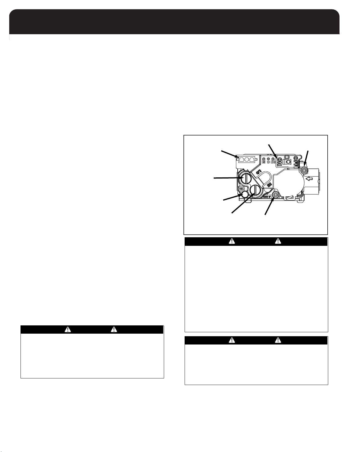
URNACE OPERATION INFORMATION
FIGURE 3
GAS VALV E
F
During the heating season, the operation of the furnace is
ully automatic.
f
o Start The Furnace:
T
. First read these instructions and safety notices
1
thoroughly.
2. Set the thermostat to the lowest setting.
3. Ensure that all supply air registers and return air grilles
are open.
4. Turn off the electric power to the furnace.
. Remove the burner access door.
5
6. Ensure that the appliance manual shutoff valve is in the
"ON" position. The valve handle is normally in-line
with the gas pipe and valve body when it is in the "ON"
position perpendicular to the gas piping and valve
body when it is in the "OFF" position.
7. Wait 5 minutes to clear out any gas. If, after this time
you smell gas, STOP. Turn the appliance manual shutoff
valve to the "OFF" position. If burning propane or
other LP gas, smell for gas near the floor since propane
and butane are both heavier than air. If after this time
you do not smell gas, continue to the next step.
8. Gas valve: Ensure that the Gas Valve Control is in the
"ON" position, see Figure 3 at right.
9. Replace the burner access door, ensuring that it is
properly in place.
10. Restore the electric power to the furnace.
11. Adjust the thermostat to the desired setting. If the
thermostat also controls an air conditioning system,
ensure that the thermostat system switch is in the
"HEAT" or "AUTO" mode.
If this is the first time that the furnace has undergone a trial
ignition since installation, or if there has been work done
on the gas lines, the furnace might not light because of air
trapped in the gas supply line.
Simply turn the thermostat down to its lowest setting, wait
five minutes, then adjust the thermostat to the desired
setting. If the problem persists, proceed to the
Down Procedure
gas supplier
If you intend to be away from home for lengthy periods of
time during the non-heating season, it is advisable to follow
the furnace shut down procedure.
and call your installer, service agency or
.
Furnace Shut
WARNING
urnace Shutdown Procedure
F
1. Set the thermostat to its lowest setting.
2. Shut off electric power to the furnace.
3. Turn the appliance manual shutoff valve to the "OFF"
osition.
p
4. Remove the burner access door, move the manual gas
control switch to the "OFF" position, then reinstall the
burner access door.
f you intend to be away from home for lengthy periods of
I
time during the nonheating season, it is advisable to follow
the furnace shutdown procedure.
Inlet Pressure
Post Set Screw
3 Pin Connector
Regulator
Adjustment
Vent
Regulator
Adjustment
On/Off Switch
Outlet Pressure
Post Set Screw
WARNING
DEVICES ATTACHED TO EITHER THE VENT OR
COMBUSTION AIR INTAKE FOR THE PURPOSES OF
EXCEEDING THE LIMITATIONS DESCRIBED IN THE
INSTALLATION MANUAL, INCLUDING FIELD INSTALLED
INDUCED BLOWER FANS HAVE NOT BEEN TESTED AND
ARE NOT INCLUDED IN THE DESIGN CERTIFICATION OF
THE FURNACE.
THE MANUF
SPECULATE ON THE EFFECTS OF SUCH MODIFICATIONS,
AND CANNOT AND WILL NOT BE RESPONSIBLE FOR
Y OR DAMAGE CAUSED BY THE USE OF SUCH
INJUR
UNTESTED AND/OR UNCERTIFIED DEVICES, ACCESSORIES
OR COMPONENTS.
ACTURER CANNOT AND WILL NOT
NEVER USE TOOLS TO TURN A MANUAL GAS CONTROL
HANDLE. IF THE CONTROL HANDLE WILL NOT TURN BY
HAND, DO NOT A
COULD RESULT IN FIRE OR EXPLOSION RESULTING IN
SERIOUS PERSONAL INJURY OR DEATH, OR PROPERTY
DAMAGE. CALL A QUALIFIED INSTALLATION
CONTRACTOR, SERVICE AGENCY OR GAS SUPPLIER.
TTEMPT TO FORCE IT. DOING SO
WARNING
IMPROPER INSTALLATION, ADJUSTMENT, ALTERATION,
SERVICE OR MAINTENANCE CAN CAUSE PROPERTY
DAMAGE, PERSONAL INJURY OR DEATH
FOR ASSISTANCE OR ADDITIONAL INFORMA
CONSULT A QUALIFIED INSTALLER, SERVICE AGENCY, OR
YOUR GAS SUPPLIER.
2
TION,

AINTENANCE
FIGURE 4
AIR FILTER
M
Replacing Air Filter
1. Disconnect electrical power to the furnace.
2. Pull the filter out the front.
3. Replace with a fresh filter and reconnect power to the
furnace. The filter will have an arrow indicating proper
airflow direction.
O NOT OPERATE YOUR FURNACE (OR AIR CONDITIONER)
D
WITHOUT AN AIR FILTER.
WARNING
DISCONNECT THE ELECTRICAL POWER TO THE FURNACE
BEFORE ATTEMPTING ANY MAINTENANCE. FAILURE TO
DO SO MAY CAUSE ELECTRICAL SHOCK RESULTING IN
SEVERE PERSONAL INJURY OR DEATH.
Consult your installation contractor or service technician if
you have any questions on filters.
The furnace should be well supported on a level floor or
•
by the means used to suspend the furnace in a horizontal
configuration. Base support should be physically sound
without sagging, cracks, gaps, etc. around the base so as
to provide a seal between the support and the base.
• Check the furnace for obvious signs of deterioration.
The gas burner should be observed from time to time
•
during the heating season to ensure that the flames are
clean and blue. A bit of orange color in the flame is not
likely to be a problem and is probably dust particles
urning. If you observe lazy yellow flames, call your
b
heating or service contractor immediately. The yellow
flames inevitably lead to soot buildup.
Furnace Appearance
The furnace exterior finish is a durable automotive-like
coating. It may be washed with mild soap if necessary.
Galvanized metal surfaces require no maintenance.
Cleaning
It is advisable to keep dust buildup on warm surfaces to a
minimum, since dust, in some cases, can be combustible.
Dust buildup in the circulating fan can impair blower
performance; therefore, reduce efficiency. Because the
blower wheel is fastened directly to the blower motor, we
recommend that major cleaning be left to your service
contractor.
Lubrication
Minimal lubrication is required for your furnace. The
induced blower assembly motors have sealed bearings. The
bearings contain permanent special purpose lubricants.
Attempting to force common oil into the induced blower
motor bearings will deteriorate the original lubricant and
shorten bearing life.
Routine Examination
It is good practice to give a quick inspection of your furnace
each time you inspect or clean the air filter. Things to check:
• All areas around the vent connector and chimney
should be clear and free of obstructions.
Check the venting to ensure that it is still fastened to
•
the furnace. It should not sag and should have a slope
upwards to the chimney
without holes or excessive corrosion.
• The return air duct connection must be sound and
securely fastened to the furnace casing. In most cases,
the filter rack provides the means to connect the return
air to the furnace. There should be no return air inlets
in the vicinity of the furnace.
• All ductwork should be secured to the furnace, and all
ductwork should be solidly supported throughout the
heating system.
. It should be physically sound,
CAUTION
DO NOT PERMIT WATER OR CLEANING SOLUTIONS TO
ENTER THE ELECTRIC MOTOR.
The burner area should be inspected and cleaned
periodically. Be careful when cleaning around the burner
area. The hot surface igniter is fragile and will break easily.
Do not touch the hot surface igniter or flame rod.
WARNING
NEVER ATTEMPT TO CLEAN THE BURNER AREA WHILE THE
BURNERS ARE OPERATING. DOING SO MAY RESULT IN
EXPLOSION OR FIRE RESULTING IN SEVERE PERSONAL
Y OR DEATH.
INJUR
ARNING
W
ALWAYS DISCONNECT THE ELECTRICAL SUPPLY TO THE
FURNACE BEFORE REMOVING THE BURNER
COMPARTMENT ACCESS DOOR.
CAUTION
THE FURNACE SHOULD BE OPERA
PLACE. NEVER OPERATE THE FURNACE WITH THE BLOWER
DOOR REMOVED EXCEPT FOR SER
TED WITH ALL PANELS IN
VICE PURPOSES.
3
The furnace achieves its mid-efficiency in two general areas.
First, there is no wasteful standing pilot. The furnace
consumes no gas in between cycles. Secondly, the furnace is
designed to allow very small amounts of excess air in the
combustion process. Older furnaces had heat exchangers
that were commonly 40% larger than necessary for
omplete combustion. While this prevented the creation of
c
carbon monoxide, the heated excess air was expelled up the
chimney where it could not benefit the interior of the
home. Special safety controls now prevent the formation of
carbon monoxide.
IMPORTANT: Your furnace should be cleaned and
inspected annually by a trained and qualified service
technician.
Your service technician has the knowledge and test
equipment to determine the condition of your furnace.
ARNING
W
THE EXHAUST GASES FROM THIS FURNACE CONTAIN
CHEMICALS, WHICH ON SOME OCCASIONS MAY
INCLUDE CARBON MONOXIDE (CO). CARBON
MONOXIDE IS AN ODORLESS, TASTELESS, CLEAR
COLORLESS GAS, WHICH IS HIGHLY TOXIC. EVEN LOW
CONCENTRATIONS ARE SUSPECTED OF CAUSING BIRTH
DEFECTS AND OTHER REPRODUCTIVE HARM.
UL AND CUL RECOGNIZED CO DETECTORS ARE
RECOMMENDED FOR ALL BUILDINGS EQUIPPED WITH
FOSSIL FUEL BURNING APPLIANCES. ALL CO DETECTORS
SHOULD BE INSTALLED IN ACCORDANCE WITH THEIR
MANUFACTURER’S INSTRUCTIONS AND APPLICABLE
LOCAL BUILDING CODES.
equence Of Operation
S
1. Thermostat, responding to cool room, calls for heat.
2. Combustion air blower begins.
. After 15 second prepurge, hot surface igniter warms up.
3
4. After approximately 5 seconds, the gas valve will open,
and the burners ignite.
5. Thirty seconds after the burners ignite and flame sense
is proven, the main blower starts on the heating speed.
. System remains in this state until the room air
6
temperature rises causing the thermostat to terminate
its call for heat.
7. The gas valve shuts off; the burners extinguish.
8. After brief postpurge period, (5 seconds), the
combustion air fan stops. The main blower continues to
run. Elapsed time ranges from 60 seconds to 180
seconds, depending on the manufacturer’s requirement.
9. The furnace remains idle until the next call for heat.
Variations
If your system includes air conditioning, your thermostat
(supplied by the installer) will likely have two switches. The
first switch is the system switch. The switch settings usually
include HEAT, COOL, and OFF. Some thermostats have system
switches which include HEAT, COOL, AUTO, and OFF. The
system switch must be in the HEAT or AUTO position for the
furnace to run.
The second switch is the fan switch. It usually has settings of
ON and AUTO. The fan switch may be in either position
when using the furnace. If the fan switch is set to ON, the
main blower will run continuously, and the blower delays
mentioned in the sequence of operation points 5 and 9 will
be ignored.
Illustrations cover the general appearance of the units at the time of publication and the manufacturer reserves the right to
make changes in design and construction at any time without notice.
For replacement parts contact:
Airwell Fedders North America
2 Centre Drive, Monroe Township, NJ 08831
Phone: 1-800-332-6658
4
 Loading...