

Installation, Operation and Maintenance
MODEL F80A
CATEGORY I NATURAL GAS AND LP GAS
MID EFFICIENCY WARM AIR FURNACE
TABLE OF CONTENTS
INTRODUCTION . . . . . . . . . . . . . . . . . . . . . . .1
SAFETY . . . . . . . . . . . . . . . . . . . . . . . . . . . . . .1
CODES . . . . . . . . . . . . . . . . . . . . . . . . . . . . . .2
FURNACE SIZING . . . . . . . . . . . . . . . . . . . . . .3
LOCATION of UNIT . . . . . . . . . . . . . . . . . . . .3
INSTALLATION POSITIONS . . . . . . . . . . . . . . .4
AIR CONDITIONING . . . . . . . . . . . . . . . . . . . .4
INSPECTION/ACCESS PANEL . . . . . . . . . . . . .4
CLEARANCES . . . . . . . . . . . . . . . . . . . . . . . . .5
DIMENSIONS . . . . . . . . . . . . . . . . . . . . . . . . .5
DUCTWORK . . . . . . . . . . . . . . . . . . . . . . . . . .6
DETERMING COMBUSTION AIR . . . . . . . . . .7
FURNACE VENTING . . . . . . . . . . . . . . . . . . . .8
GAS SUPPLY . . . . . . . . . . . . . . . . . . . . . . . . .12
CONVERSIONS . . . . . . . . . . . . . . . . . . . . . . .13
HIGH ALTITUDE & AIRFLOW
SPECIFICATION TABLES . . . . . . . . . . . . . . . .14
ELECTRICAL SPECIFICATIONS . . . . . . . . . . .15
START UP PROCEDURES/
SEQUENCE OF OPERATION . . . . . . . . . . . . .17
AIR FLOW . . . . . . . . . . . . . . . . . . . . . . . . . . .19
ADJUSTING BLOWER SPEEDS . . . . . . . . . . .19
MAINTENANCE
TROUBLESHOOTING . . . . . . . . . . . . . . . . . .21
WIRING DIAGRAM . . . . . . . . . . . . . . . . . . . .25
. . . . . . . . . . . . . . . . . . . . . .
20
For future reference write down the model, serial
number, and date of purchase. Use these numbers in
any correspondence or service calls concerning your
furnace.
Model
Serial Number
Date of Purchase
Keep these instructions for future reference.
Please read the operating instructions and safety
precautions carefully and thoroughly before installing
and operating your furnace. Keep this manual in a
safe place for future reference.
USER’S INSTRUCTION GUIDE
LOCATED AFTER PAGE 25 OF THIS
INSTALLATION, OPERATION AND
MAINTENANCE MANUAL
23-23-0427N-006
MODEL F80A
NTRODUCTION
I
This gas fired midefficiency (non-condensing) furnace is an
p flow, counterflow or horizontal flow warm air furnace
u
suitable for residential and light commercial heating
applications from 35,000 to 135,000 BTU/Hr.
his appliance is a CGA / AGA design certified as a Category I
T
chimney vent central forced air furnace with all combustion
air supplied from the ambient air around the furnace.
urnace models F80A50, F80A70, F80A85, F80A100,
F
F80A115 and F80A135 may be field converted from natural
gas to LP gas using Kit No. 30482, or may be field converted
from LP gas to natural gas using Kit No. 30551. Contact
urnace
anufacturer for conversion kit availability. *
m
model F80A35 cannot be converted to LP, and is not
approved for conversion.
The furnace is shipped completely assembled. Please inspect
for damage, as the furnace is unpacked.
SAFETY
Throughout the manual, symbols and words are used to
draw attention to potentially hazardous conditions.
DANGER
THIS INDICATES AN IMMINENTLY HAZARDOUS
SITUATION WHICH, IF NOT AVOIDED, WILL RESULT IN
DEATH OR SERIOUS INJURY.
WARNING
THIS INDICATES A POTENTIALLY HAZARDOUS
SITUATION WHICH, IF NOT AVOIDED, COULD RESULT IN
DEATH OR SERIOUS INJURY.
CAUTION
THIS INDICATES A POTENTIALLY HAZARDOUS
SITUATION, WHICH, IF NOT AVOIDED, MAY RESULT IN
MINOR OR MODERATE INJURY.
F
. Always install furnace to operate within the furnace’s
6
intended temperature rise range with a duct system
which has an external static pressure within the
allowable range, as specified in the Furnace Sizing
section on page 3, the Ductwork section on page 6, and
he Airflow section on page 19 of these instructions.
t
7. When a furnace is installed so that the supply ducts carry
air circulated by the furnace to areas outside the space
ontaining the furnace, the return air shall also be
c
handled by duct(s) sealed to the furnace casing and
terminating outside the space containing the furnace.
(Furnace for heating the home located in the attached
arage, for example).
g
8. A gas fired furnace for installation in a residential
garage must be installed so that the burners and ignitor
are no less than 18 inches above the floor. The furnace
must be located, or protected to avoid physical damage
by vehicles.
THIS FURNACE IS NOT TO BE USED FOR TEMPORARY
9.
HEATING FOR BUILDINGS UNDER CONSTRUCTION.
10. Nox Baffles are factory installed in the heat exchanger
tubes of this furnace, and must remain installed
regardless of fuel being used.
DANGER
DO NOT INSTALL THIS FURNACE IN A MOBILE HOME!
THIS FURNACE IS NOT APPROVED FOR INSTALLATION IN
A MOBILE HOME. DOING SO COULD CAUSE FIRE,
PROPERTY DAMAGE, PERSONAL INJURY OR LOSS OF
LIFE.
WARNING
THE FURNACE CONTAINS FOIL COVERED FIBERGLASS
INSULATION. INHALATION OF FIBERGLASS PARTICLES IS
ASSOCIATED WITH RESPIRATORY DISEASE INCLUDING
CANCER.
SAFETY RULES:
1. Use this furnace only with type of gas approved for this
furnace. Refer to the furnace rating plate.
2. Install this furnace only in dry indoor locations
(protected from weather).
3. Provide adequate combustion and ventilation air to the
furnace space as specified in the Determining
Combustion Air section on page 7 of these instructions.
4. Combustion products must be discharged outdoors.
Connect this furnace to an approved vent system only, as
specified in the Furnace Venting section on page 8 of
these instructions.
5. Never test for gas leaks with an open flame. Use a
commercially available soap solution made specifically
for the detection of leaks to check all connections as
specified in the Gas Supply section on page 12 of these
instructions.
WARNING
THE FUEL SUPPLIER NORMALL
GAS AND PROP
MAY NOT BE PERCEIVABLE. INSTALLATION OF UL AND
CUL RECOGNIZED FUEL GAS DETECTORS INSTALLED IN
ACCORDANCE WITH THEIR MANUFACTURER’S
INSTRUCTIONS IS RECOMMENDED AS AN ADDITIONAL
MARGIN OF SAFETY
ANE. IN SOME CASES, THE ODORANT
.
Y ODORIZES NATURAL
DANGER
FIRE OR EXPLOSION HAZARD
If the information in these instructions is not followed
exactly, a fire or explosion may result, causing property
damage, personal injury or loss of life.
CAUTION
MAKE SURE TO REMOVE FOAM BLOWER HOUSING
SHIPPING SUPPORTS BEFORE OPERATING FURNACE.
SHIPPING SUPPORTS ARE LOCATED ON THE BOTTOM
RIGHT AND BOTTOM LEFT SIDES OF BLOWER HOUSING.
1
WARM AIR FURNACE
DANGER
WHAT TO DO IF YOU SMELL GAS:
• DO NOT TRY TO LIGHT ANY APPLIANCE
• DO NOT TOUCH ANY ELECTRICAL SWITCH; DO NOT
USE ANY PHONE IN YOUR BUILDING
IMMEDIATELY CALL YOUR GAS SUPPLIER FROM A
•
EIGHBOR’S PHONE, OR A CELLULAR PHONE FROM A
N
LOCATION WELL AWAY FROM THE BUILDING.
FOLLOW THE GAS SUPPLIER’S INSTRUCTIONS.
IF YOU CANNOT REACH YOUR GAS SUPPLIER, CALL
•
THE FIRE DEPARTMENT
• DO NOT ENTER THE BUILDING UNTIL AUTHORIZED TO
DO SO BY THE GAS SUPPLIER OR THE FIRE
DEPARTMENT
IMPROPER INSTALLATION, OPERATION, ADJUSTMENT,
ALTERATION, SERVICE OR MAINTENANCE CAN CAUSE
INJURY, PROPERTY DAMAGE OR LOSS OF LIFE. REFER TO
THIS MANUAL FOR PROPER INSTALLATION, OPERATION,
VICE, AND MAINTENANCE INSTRUCTIONS.
SER
A QUALIFIED INSTALLER, SERVICE AGENCY OR
THE GAS SUPPLIER MUST PERFORM
INSTALLATION AND SERVICE.
DO NOT DESTROY THIS MANUAL
PLEASE READ CAREFULLY AND KEEP IN A SAFE PLACE
FOR FUTURE REFERENCE BY A SERVICE TECHNICIAN.
WARNING
THESE INSTRUCTIONS ARE INTENDED AS AN AID TO
QUALIFIED SERVICE PERSONNEL FOR PROPER
INSTALLATION, ADJUSTMENT AND OPERATION OF THIS
FURNACE. READ THESE INSTRUCTIONS THOROUGHLY
BEFORE ATTEMPTING INSTALLATION OR OPERATION.
FAILURE TO FOLLOW THESE INSTRUCTIONS MAY RESULT
IN IMPROPER INSTALLATION, ADJUSTMENT, SERVICE OR
MAINTENANCE, POSSIBLY RESULTING IN FIRE,
ELECTRICAL SHOCK, CARBON MONOXIDE POISONING,
EXPLOSION, PROPERTY DAMAGE, PERSONAL INJURY OR
DEATH.
DO NOT STORE OR USE GASOLINE OR OTHER
FLAMMABLE VAPORS AND LIQUIDS, OR OTHER
COMBUSTIBLE MATERIALS IN THE VICINITY OF THIS OR
ANY OTHER APPLIANCE.
WARNING
THE EXHAUST GASES FROM THIS FURNACE CONTAIN
CHEMICALS, WHICH ON SOME OCCASIONS MAY
INCLUDE CARBON MONOXIDE (CO). CARBON
MONOXIDE IS AN ODORLESS, TASTELESS, CLEAR
COLORLESS GAS, WHICH IS HIGHL
CONCENTRA
DEFECTS AND OTHER REPRODUCTIVE HARM.
UL AND CUL RECOGNIZED CO DETECTORS ARE
RECOMMENDED FOR ALL BUILDINGS EQUIPPED WITH
FOSSIL FUEL BURNING APPLIANCES. ALL CO DETECTORS
SHOULD BE INST
MANUFACTURER’S INSTRUCTIONS AND APPLICABLE
LOCAL BUILDING CODES.
TIONS ARE SUSPECTED OF CAUSING BIR
ALLED IN ACCORDANCE WITH THEIR
Y TOXIC. EVEN LOW
TH
DANGER
HEN THIS FURNACE IS INSTALLED IN A RESIDENTIAL
W
GARAGE, IT MUST BE INSTALLED SO THE BURNERS AND
IGNITION SOURCE ARE LOCATED NO LESS THAN 18
INCHES ABOVE THE FLOOR TO PREVENT THE RISK OF
IGNITING FLAMMABLE VAPORS WHICH MAY BE
RESENT IN THE GARAGE.
P
THE FURNACE MUST BE LOCATED OR PROTECTED TO
AVOID PHYSICAL DAMAGE BY VEHICLES.
FAILURE TO HEED THESE WARNINGS CAN CAUSE A FIRE
OR EXPLOSION, RESULTING IN PROPERTY DAMAGE,
PERSONAL INJURY OR LOSS OF LIFE.
CODES:
This furnace must be installed:
• In accordance with all local codes, bylaws and
regulations by those authorities having jurisdiction
• In the United States, this furnace must be installed in
accordance with the current ANSI Z223.1 (NFPA 54)
National Fuel Gas Code
• In Canada, this furnace must be installed in
accordance with the current CAN/CGA -B149
Installation Code for Fuel Burning Appliances
Electrical connections must be made in accordance
with:
• Any applicable local codes, bylaws and regulations
• Canada: current edition of CAN/CSA C22.1, Canadian
Electrical Code (Part 1)
• United States: current edition of ANSI/NFPA 70,
National Electrical Code
Codes and additional information may be obtained
from:
• American Gas Association
1515 Wilson Boulevard
Arlington, VA, 22209
703-841-8400
National Fire Protection Association
•
1 Batterymarch Park
Quincy, MA, 02269-9101
617-770-3000
Canadian Gas Association
•
Suite 1, 243 Consumers Road
North York, ON, M2J 5E3
416-498-1994
2
MODEL F80A
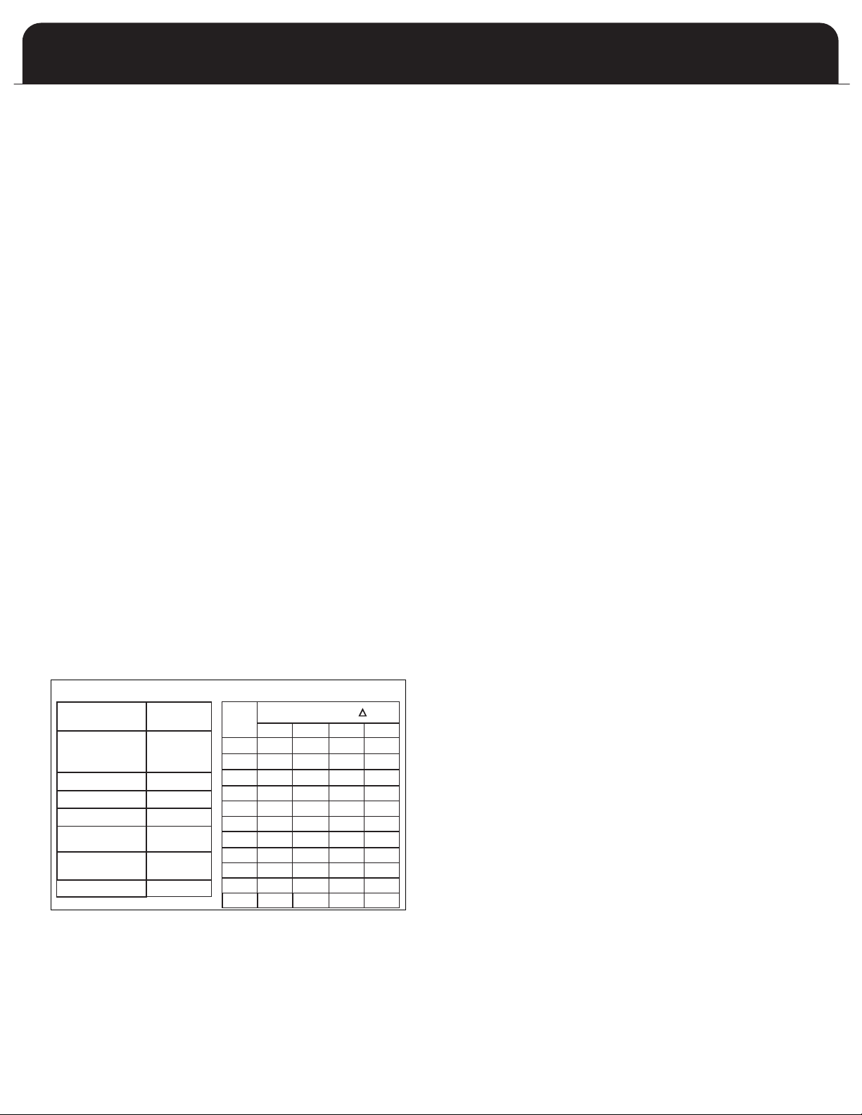
TABLE 1A
FURNACE TEMPERATURE RISE
Fur nac e Mod
Model
el Tem per atu re
Rise
35 – 65 F
30 – 60 F
35 – 65 F
30 – 60 F
35 – 65 F
30 – 60 F
30 – 65 F
TAB
LE 1B
TYPICAL A IR FLOW
CF M Re qu ired for a T of:
35 45
55 65
35-2
50-3
70-3
70-4
85-3
85-4
100-3
100-4
100-5
115-5
35-2
50-3
70-3
70-4
85-3
85-4
100-4
100-5
115-5
737 574 469 397
1053 819 670 567
1433 1114 912 771
1433 1114 912 771
1791 1393 1140 964
1791 1393 1140 964
2107 1639 1341 1134
100-3
2107 1639 1341 1134
2107 1639 1341 1134
2423 1884 1542 1305
135-5
135-5
2844 2212 1810 1532
URNACE SIZING
F
The maximum hourly heat loss for each heated space shall
e calculated in accordance with the procedures described
b
in Manual J titled, "Load Calculation" published by the Air
Conditioning Contractors of America, or by any other
method which is suitable for local conditions, provided the
esults obtained are in substantial agreement with, and not
r
less than those obtained using the procedure described in
their manual.
n Canada, the maximum hourly heat loss for each heated
I
space shall be calculated in accordance with the procedures
described in the manuals of the Heating, Refrigeration and
Air Conditioning Institute of Canada (HRAI), or by any other
method which is suitable for local conditions, provided the
results obtained are in substantial agreement with, and not
less than those obtained using the procedure described in
their manuals.
If the installation is a retrofit application, do not rely on the
capacity of the existing heating equipment as a method to
size the new furnace. Many of the heat transfer multiples
listed in earlier versions of load calculation manuals were
much higher than those listed in more recent editions. It is
possible that energy saving measures have been completed
since the installation of the existing furnace. This might
include additional insulation in the attic or walls, the
application of sprayed foam insulation, the addition of
storm windows and doors, weather stripping, caulking, etc.
Many of the older furnaces were equipped with large belt
drive blower systems, operating at low RPMs. If replacing an
existing furnace, be sure that the existing ductwork can
handle the amount of airflow necessary for a reasonable
temperature rise. Most older gas furnaces operated with a
system temperature rise of 70 - 100°F. This series furnace has
been designed for operation with a system temperature rise
(DT) of 35 - 65°F or 30 – 60°F depending on which model is
being installed. See Table 1A below. If the furnace selected
has an identical output capacity as the original furnace, a
substantial increase in system airflow will be required. See
able 1B below
T
Existing ductwork should be assessed for its air handling
capabilities. For residential applications, the recommended
air velocity of a supply air trunk duct is 700 feet per minute
(fpm), and should not exceed 900 fpm. The recommended
air velocity of a supply air branch run is 600 fpm, and should
not exceed 900 fpm. These values are slightly lower for
flexible ducting. The recommended air velocity of a return
air trunk duct is 600 fpm, and should not exceed 700 fpm.
The recommended and maximum air velocity of a return air
branch is 600 fpm.
.
he equal friction chart, as published by ASHRAE and HRAI,
T
is the basis for the various air duct calculators available
through heating supply companies.
NOTE: The return air system is equally as important as the
supply air system. An undersized return air system will
prevent sufficient quantities of air from reaching the supply
ir system, properly sized or otherwise, and will
a
consequently reduce the service life of the furnace and its
components.
LOCATION of UNIT
GENERAL:
1. The furnace is not weatherized. Select a dry indoor
location.
2. Select a location where the furnace venting can be
routed between the furnace and the chimney or B-Vent
with a minimum of lengths and fittings. Be sure to
check that the proposed routing will meet code
requirements with respect to minimum clearances.
3. Select a location as near as possible to the existing or
proposed duct system.
4. The furnace location must permit access for servicing,
and be within the clearance to combustibles guidelines
as marked on the appliance rating plate.
5. The furnace should be installed on a firm base when
installed in the upflow position. This is typically a
concrete floor if installing the furnace in a basement.
6. If the furnace is being installed so that the return air
will enter through the bottom, the perimeter of the
furnace must be properly supported.
7. When installed in the horizontal position, the furnace
may be supported from the bottom, or suspended.
8. When installed in the down flow position on a
combustible floor, subbase kit #30476 is required
(contact manufacturer for availability).
OTHER CONSIDERATIONS:
• This furnace is not to be used for temporary heating of
buildings or structures under construction.
• If this furnace is to be used with air conditioning and is
to be installed in an area over a finished ceiling or
living area, install a field fabricated auxiliary drain pan
under the furnace to protect that area from accidental
condensate spills. The auxiliary pan should be large
enough to collect accidentally spilled condensate from
the air conditioning evaporator coil assembly if
applicable. Follow local codes.
These furnaces are approved for installation in attics,
•
alcoves, utility rooms, closets and crawlspaces. If this
furnace is to be installed in a utility room, be sure that
it is located in such a way as to allow access for
servicing or the removal of any other appliance, (hot
water heater, for example).
If the furnace is to be installed in a garage, the burners
•
must be a minimum of 18 inches (460 mm) above the
floor.
If the furnace is to be installed in a commercial (repair)
•
garage, the burners must be a minimum of 4.5 feet
(1375 mm) above the floor.
The furnace must be protected from physical damage
•
by metal barriers or other acceptable means.
3
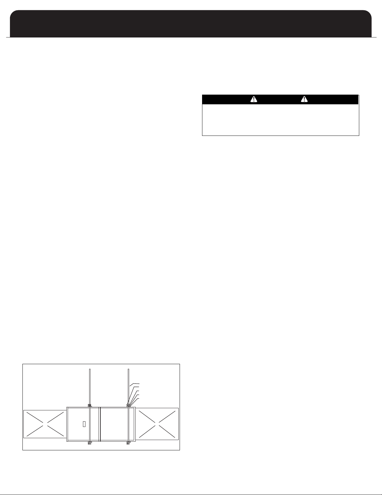
SUGGESTED METHOD FOR
SUSPENDING HORIZONTAL FURNACE
ALLOW ENOUGH ANGLE
IRON OVERHANG TO
PERMIT OPENING THE
BLOWER DOOR
3/8 INCH THREADED ROD
2 INCH ANGLE IRON
JAM NUTS
LOCK WASHER
FLATWASHER
SUPPLY AIR PLENUM
RETURN AIR PLENUM
If the furnace is to be located in an area where the
•
combustion air is laden with chemical compounds such
as bromine, chlorine or fluorine, as may be found in
swimming pool chemicals, laundry detergents, etc., use
outdoor air for combustion. These compounds when
xposed to flame, form acids, which attack the heat
e
exchanger and other components.
A partial list of these contaminants includes:
- Aerosols, particularly CFC based aerosols
Air fresheners
-
- “Airplane” glue and similar cements
- Ammonia, as is commonly found in permanent wave
solutions used in women’s hair dressing salons
- Anti-static fabric softeners used in clothes dryers
- Carbon tetrachloride
- Chlorinated cleaners and waxes
- Chlorine and bromine based swimming pool chemicals
and treatments
- Deicing salts or chemicals, rock salt, etc.
- Dry cleaning solutions such as perchloroethylene
- Halogen based refrigerants including R-12 and R-22
- Hydrochloric acid, muriatic acid, or other acid based
masonry washing compounds
- Polyurethane and similar derivatives fumes
- Printer’s inks, paint removers, furniture strippers,
varnishes, varsol, toluene, etc.
- Water softener salts and chemicals
INSTALLATION POSITIONS
NONSUSPENDED INSTALLATION
Maintain clearances to combustibles as outlined in Table 2
on page 5. The furnace must be supported in such a way as
to not allow twisting or sagging of the cabinet.
SUSPENDED INSTALLATION
Refer to Figure 1 (below). Maintain clearances to
combustibles as outlined in Table 2 on page 5. The furnace
may be suspended by field fabricating a cradle of angle iron
and threaded rod. Secure the furnace with 2 inch minimum
slotted angle or equivalent, as shown in Figure 1 (below).
The furnace must be supported in such a way as not to
allow twisting or sagging of the cabinet. Position the
supports so as not to interfere with accessing the burner
and blower compartments.
FIGURE 1: SUSPENDED INST
ALLATION
WARM AIR FURNACE
PFLOW INSTALLATION
U
This furnace comes assembled for installation in the upflow
osition and ready for vertical venting. In the event that the
p
furnace will be installed in another position, the following
guidelines should be followed.
COUNTERFLOW INSTALLATION
WARNING
HEN INSTALLED IN THE COUNTERFLOW POSITION ON
W
A COMBUSTIBLE FLOOR, SUBBASE KIT #30476 IS
REQUIRED. FAILURE TO INSTALL SUBBASE KIT COULD
RESULT IN FIRE, DEATH OR SERIOUS INJURY.
The opening in the floor must provide adequate clearances
to the combustible material.
According to the Clearances to Combustibles Table 2 on
page 5, 1/2 inches clearance will be required between the
plenum and the combustible material. If installed on a
non-combustible material, zero clearance is required.
Inducer position changes required shall be performed in
accordance with the inducer rotation instructions in the
Furnace Venting section on page 8 of this manual. In the
counterflow installation, this furnace can only vent through
the left or right side of the furnace.
HORIZONTAL INSTALLATION
Inducer position changes required shall be performed in
accordance with the inducer rotation instructions in the
Furnace Venting section on page 8 of this manual. In the
horizontal installation, it is not permissible to vent
downwards. Therefore the orientation of left or right
horizontal position will determine the inducer orientation.
NOTE: It is not permissable to use a rear return on this
furnace although side and end returns may be used.
AIR CONDITIONING
This furnace may be used as part of an air conditioning
system. The furnace wiring and control system are “air
conditioning ready”. There are the following factors to
consider:
• The air conditioning evaporator coil must be
downstream of the heat exchanger. The cooled air
passing over the warm ambient air inside the heat
exchanger tubes can cause condensation inside the
tubes, resulting in corrosion and premature failure.
A parallel duct system can be installed to direct the air
•
from the furnace through the evaporator coil only. Use
dampers or other means to bypass the heat exchanger.
If [summer/winter] dampers are used, they should be
interlocked to prevent system operation unless the
dampers are in the full open or full closed position.
INSPECTION / ACCESS PANEL
If an air conditioning coil is not to be used in the supply air
plenum, it is recommended that the outlet duct be provided
with a removable access panel, which is accessible when
installed so the heat exchanger may be viewed for possible
openings using light assistance or a probe that can be
inserted for sampling the air stream. The access cover must
be fabricated in such a manner as to prevent leaks.
4
MODEL F80A
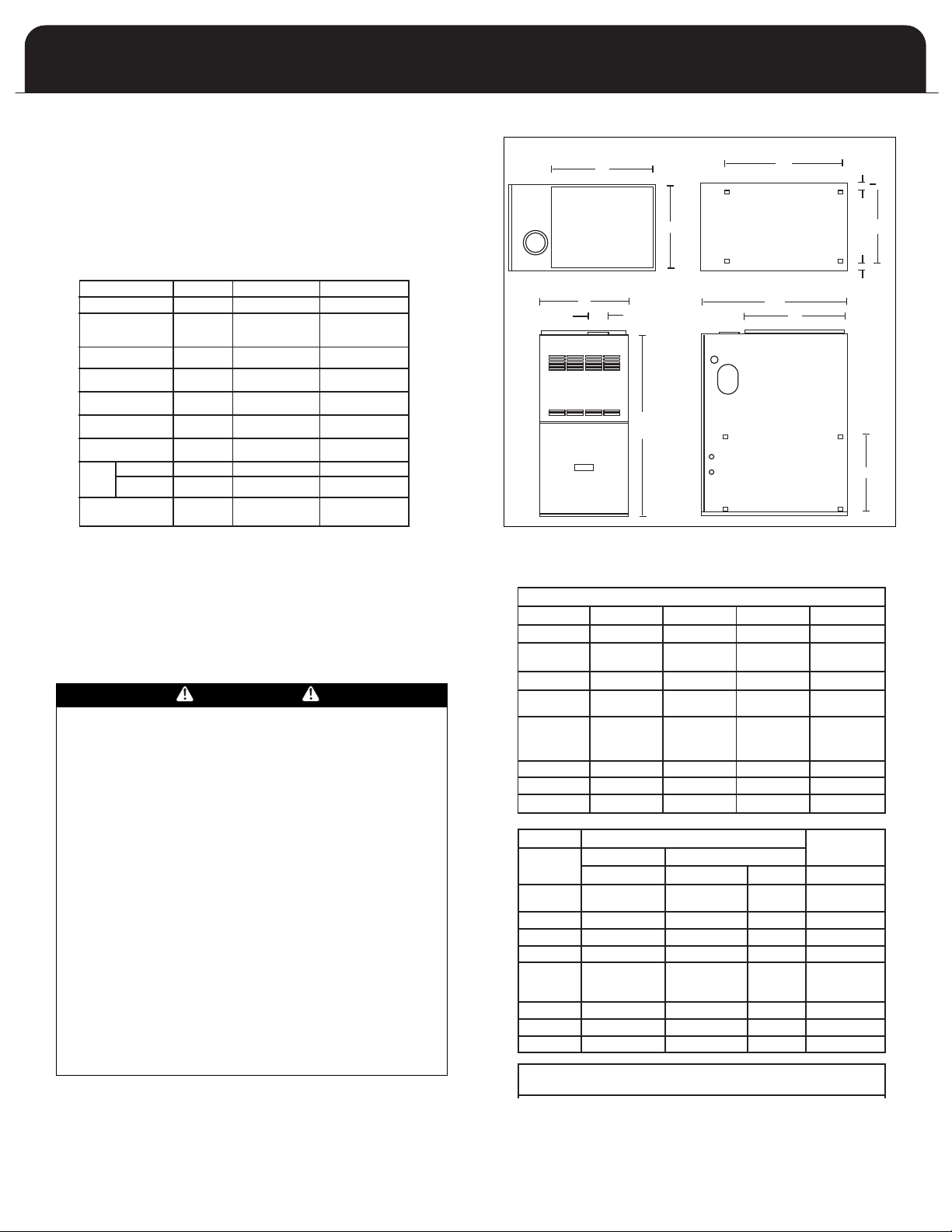
DIMENSIONS (Inche
MODEL WIDTH DEPTH HEIGHT SUPPLY
A
35-2 14-1/2 29 35 13-1/2 x 19
50-3 14-1/2 29 35 13-1/2 x 19
70-3 16 29 35 15 x 19
70-4 17-1/2 29 35 16-1/2 x 19
85-3 17-1/2 29 35 16-1/2 x 19
85-4
4100- 20-1/2 29 35 19-1/2 x 19
100-5 20-1/2 29 35 19-1/2 x 19
115-5 22 29 35 21 x 19
MODEL RETURN
S
35-2 14 x 22 13-1/2 x 22 1/2 3
1
50-3 14 x 22 13-1/2 x 22 1/2 3
1
70-3 14 x 22 14-1/2 x 22 3/4 4
70-4 14 x 22
2
85-3 14 x 22 14-1/2 x 22 1-1/2 4
85-4
4100- 14 x 22 16 x 22 2-1/4 4
100-5 14 x 22
2
115-5 14 x 22
2
1
Vent outlet 4” -
2
Two return air openings required
G
A
H
C
G
B
F
D
J
L
L
K
DIMENSIONS (Inches)
MODEL WIDTH DEPTH HEIGHT SUPPLY
ABCFx G
35-2
14-1/2 29 35 13-1/2 x 19
50-
3
70-3 16 29 35 15 x 19
70-4
17-1/2 29 35 16-1/2 x 19
85-3
85-4
4
20-1/2 29 35 19-1/2 x 19
100-
3100-
100-5 20-1/2 29 35 19-1/2 x 19
115-5 22 29 35 21 x 19
135-5 22 29 35 21 x 19
135-5
MODEL RETURN
SIDE BOTTOM
VENT
D x E J x K L H
35-2
14 x 22 13-1/2 x 22 1/2 3
1
50-3
70-3 14 x 22 14-1/2 x 22 3/4 4
70-4 14 x 22
2
14-1/2 x 22 1-1/2 4
85-3 14 x 22 14-1/2 x 22 1-1/2 4
85-4
4
14 x 22 16 x 22 2-1/4 4
100-
3100-
100-5 14 x 22
2
16 x 22 2-1/4 4
115-5 14 x 22
2
19 x 22 1-1/2 5
1
14 x 22
2
19 x 22 1-1/2 5
1
1
Vent outlet 4” - Use reducer fittings.
2
Two return air openings required
UPFLOW
COUNTERFLOW
HORIZONTAL
1" 0" 2"
1" 1" 2.5"
.5" .5" .5"
3.5"* 3.5"* 3.5"*
0" 0" 0"
0" 0" 1"**
0"*** 0"**** 0"
6" 6" 6"
1" 1" 1"
CLOSET
CABINET
CLOSET
CABINET
CLOSET
CABINET
UNIT TOP
PLENUM
TOP/BOTTOM
PLENUM SIDES
UNIT FRONT
UNIT BACK
UNIT SIDES
ENCLOSURE
UNIT BASE
FLUE
PIPE
C VENT
B VENT
LEARANCES
C
Table 2 (below) provides the certified clearances to
ombustibles.
c
MPORTANT:
I
his furnace requires a minimum of 24-inches of front
T
clearance for service purposes. For this purpose, service
clearance takes precedence over clearance to combustibles.
TABLE 2: CLEARANCES TO COMBUSTIBLES
IGURE 2: DIMENSIONS
F
* 24 inches required for service
** Supply air end 1 inch / return air end 0 inches
*** Certified for closet installation on combustible flooring
**** Certified for installation on combustible flooring
only when installed on special base (part # 30476).
See the appliance rating plate affixed to the furnace
for specific model number, serial number and
clearance to combustibles information.
DANGER
COMBUSTIBLE MATERIAL MUST NOT BE PLACED ON OR
AGAINST THE FURNACE JACKET.
THE AREA AROUND THE FURNACE MUST BE KEPT CLEAR
AND FREE OF ALL COMBUSTIBLE MATERIALS INCLUDING
GASOLINE AND OTHER FLAMMABLE VAPORS AND
LIQUIDS.
PLACEMENT OF COMBUSTIBLE MATERIALS ON, AGAINST
OR AROUND THE FURNACE JACKET CAN CAUSE AN
EXPLOSION OR FIRE RESULTING IN PROPERTY DAMAGE,
PERSONAL INJUR
Y OR LOSS OF LIFE.
THE HOMEOWNER SHOULD BE CAUTIONED THA
FURNACE AREA MUST NOT BE USED AS A BROOM
CLOSET OR FOR ANY OTHER STORAGE PURPOSE.
UPFLOW FURNACES ARE DESIGN CERTIFIED FOR
INSTALLATION ON COMBUSTIBLE FLOORS. THIS SHALL
BE INTERPRETED AS A WOOD FLOOR ONLY
THE FURNACE MUST NOT BE INSTALLED DIRECTLY ON
CARPETING, VINYL TILE, OR OTHER COMBUSTIBLE
MATERIAL EXCEPT WOOD. INSTALLATION ON
COMBUSTIBLE MATERIAL CAN RESULT IN FIRE, CAUSING
PROPER
TY DAMAGE, PERSONAL INJUR
Y OR DEA
TABLE 3: DIMENSIONS
T THE
.
TH.
5
WARM AIR FURNACE
UCTWORK
D
Proper airflow is required for the correct operation of this
urnace. Insufficient airflow may cause erratic operation,
f
could cause the furnace to cycle on the high temperature
limit, and may damage the heat exchanger. Excessive
airflow may result in an excessively noisy duct system and
may result in undesirable consequences such as creating
ncomfortable drafts and causing drapes or curtains to
u
blow around.
If air conditioning is to be used with the furnace, the duct
ystem must be capable of delivering the correct amount of
s
airflow for each system.
The ductwork should be sized and constructed in
accordance with accepted industry standards. Duct sizing
and construction information may be obtained from:
• A.C.C.A. (Air Conditioning Contractors of America)
• A.S.H.R.A.E. (American Society of Heating,
Refrigeration and Air Conditioning Engineers)
• H.R.A.I. (Heating, Refrigerating and Air Conditioning
Institute (Canada)
• S.M.A.C.N.A. (Sheet Metal and Air Conditioning
Contractors’ National Association (United States)
All of the above professional organizations have duct sizing
manuals available.
The total static pressure drop of the air distribution system
should not exceed 0.5 inches water column.
NOTE:
UNITS 70-4, 100-5, 115-5 AND 135-5 MUST HAVE DUAL
RETURN AIR INLETS FOR OPTIMAL AIRFLOW AND AIR
FILTRATION. IF NOT SPECIFICALLY STATED BY THE FILTER
MANUFACTURER, FOR EFFECTIVE AIR FILTRATION, ASSUME
A MAXIMUM VELOCITY OF 300 FPM FOR DISPOSABLE TYPE
FILTERS, OR 600 FPM FOR PERMANENT TYPE FILTERS.
GUIDE:
Filter free area (in2) = 144 x (CFM / desired velocity (fpm))
IMPORTANT: Some high efficiency filters have a greater
than normal resistance to airflow. This can adversely affect
furnace operation. Ensure to check the airflow when using
any filter.
ARNING
W
DO NOT, UNDER ANY CIRCUMSTANCES, CONNECT
RETURN OR SUPPL
OTHER HEA
INSERT, STOVE, ETC. DOING SO MAY RESULT IN FIRE,
CARBON MONOXIDE POISONING, EXPLOSION,
PERSONAL INJURY, LOSS OF LIFE, OR PROPERTY
DAMAGE.
Y AIR DUCTWORK TO OR FROM ANY
-PRODUCING DEVICE SUCH AS A FIREPLACE
T
UCTWORK STEPS:
D
. Position the furnace to minimize ductwork length and
1
fittings.
. Cut open a return air inlet. The choices are:
2
a) either side
b) furnace bottom
) any combination, i.e. two sides or a side and the
c
bottom. Note: 2 return openings required for 70-4,
100-5, 115-5 and 135-5.
CAUTION
O NOT USE THE REAR PANEL AS A RETURN AIR INLET.
D
THERE IS INSUFFICIENT ROOM TO PERMIT ADEQUATE
AIRFLOW.
In all cases, cut the inlet air opening the full width of
the knockouts.
NOTE: When two return air inlets are used, both must
be equipped with filters.
3. Install the filter rack(s) (field supplied).
4. Connect the return air duct or fitting to the furnace. The
connection should be as air tight as possible to prevent
entraining combustion gases from an adjacent fuel
burning appliance, or entraining combustion air for this
furnace .
5. Ensure that there is adequate space and accessibility for
the air filter.
6. If an air conditioning evaporator coil is required,
position it on the top of the furnace. Ensure that no air
can bypass the evaporator coil.
7. Connect the supply air plenum to the supply air outlet.
Flexible duct connectors are an effective device to
prevent the telegraphing of mechanical noise from the
furnace to other parts of the home via the ductwork. If
using flexible connectors, ensure that the adjoining
duct is independently supported.
Adequate provisions for combustion and ventilation air
must be in accordance with ANSI Z223.1 (NFPA 54), section
5.3 "Air for Combustion and Ventilation" in the United
States, and CAN/CGA B149 in Canada. Check with local
authorities for any additional building codes, bylaws or
regulations.
WARNING
NEVER ALLOW THE PRODUCTS OF COMBUSTION FROM
THE FLUE TO ENTER THE RETURN AIR OR SUPPLY AIR
DUCTWORK.
ALL RETURN AIR DUCTWORK MUST BE ADEQUA
SEALED AND SECURED TO THE FURNACE WITH SHEET
METAL SCREWS. TAPE THE SHEET METAL SEAMS IN THE
VICINITY OF THE FURNACE WITH DUCT TAPE OR
SIMILAR MA
WHEN THE FURNACE IS MOUNTED ON A PLATFORM
WITH RETURN AIR THROUGH THE BOTTOM, IT MUST BE
SEALED AIR TIGHT BETWEEN THE FURNACE AND THE
RETURN AIR PLENUM. THE FLOOR OR PLA
PROVIDE SOUND PHYSICAL SUPPORT OF THE FURNACE
WITHOUT SAGGING, CRACKS OR GAPS AROUND THE
BASE, PROVIDING A SEAL BETWEEN THE SUPPORT AND
THE BASE.
AILURE TO PREVENT PRODUCTS OF COMBUSTION
F
FROM BEING CIRCULATED INTO THE LIVING SPACE CAN
CREATE POTENTIALLY HAZARDOUS CONDITIONS,
INCLUDING CARBON MONOXIDE POISONING THA
COULD RESULT IN PERSONAL INJURY OR DEATH.
6
TERIAL.
TFORM MUST
TELY
T
MODEL F80A
ETERMING COMBUSTION AIR
D
ANGER
D
READ, UNDERSTAND AND FOLLOW ALL INSTRUCTIONS
IN THIS SECTION. FAILURE TO PROPERLY VENT OR
UPPLY COMBUSTION AIR TO THIS FURNACE CAN
S
CAUSE CARBON MONOXIDE POISONING, OR AN
EXPLOSION OR FIRE, RESULTING IN PROPERTY DAMAGE,
PERSONAL INJURY OR LOSS OF LIFE.
DANGER
THIS FURNACE AND ANY OTHER FUEL BURNING
APPLIANCE MUST BE PROVIDED WITH ENOUGH FRESH
AIR FOR PROPER COMBUSTION AND VENTILATION OF
THE FLUE GASES. MOST HOMES WILL REQUIRE THAT
OUTSIDE AIR BE BROUGHT TO THE FURNACE AREA.
FAILURE TO DO SO CAN CAUSE PERSONAL INJURY OR
DEATH FROM CARBON MONOXIDE POISONING.
CASE 1:
FURNACE LOCATED IN AN UNCONFINED SPACE
Unconfined space does not necessarily mean that
combustion and ventilation will not have to be introduced
from the outdoors, particularly in airtight homes. Refer to
the appropriate installation code requirements regarding
the minimum combustion air required for all fuel burning
appliances located within the unconfined area.
If the amount of combustion and ventilation air is
insufficient to properly operate the furnace and other fuel
burning appliances within the unconfined area, it will be
necessary to supply it from the outdoors based on the
criteria used when calculating the air supply for a confined
space.
NOTE: If planning to use the inside air of an unconfined
space, remember to test for proper furnace operation (as
well as other fuel burning appliances located within the
unconfined space) with respect to adequate combustion
and ventilation air with fireplace dampers open, clothes
dryer running, bathroom exhaust fans on, kitchen range
hood on, etc.
CASE 2:
FURNACE LOCATED IN A CONFINED SPACE
A confined space, (any space smaller than the minimums
discussed in CASE 1), must have two air openings one within
12 inches of the ceiling and the other within 12 inches of
the floor
the combustion and ventilation air is being taken from
indoors or outdoors, the method outdoor air (if used) is
introduced, and taking into account any other fuel burning
appliances in the confined space.
If sufficient indoor combustion and ventilation air is
available for the furnace and all other fuel burning
appliances, even when clothes dryers, bathroom fans, range
hoods, etc. are running, size each opening according to the
appropriate installation codes.
. The air openings must be sized based on whether
OTE: If using grilles to cover the two openings, factor in
N
the free area of the grille. Typically, a grille will have a free
area approximately 50% of its nominal size. Consequently,
if the required opening is 10 inches x 10 inches , it will have
to be doubled if using a sidewall grille with 50% free area.
IMPORTANT: If an exhaust fan, fireplace, clothes dryer or
any similar device is present in the indoor area from which
the combustion and ventilation air will be drawn, negative
ressure could be a problem if natural infiltration from the
p
outdoors does not match the rate at which air is exhausted.
CASE 3:
FURNACE LOCATED IN A CONFINED SPACE, OUTDOOR
AIR FROM ATTIC OR CRAWL SPACE
In this circumstance, refer to the appropriate installation
code for the free area of the combustion and ventilation air
openings. If other fuel burning appliances are present, their
combustion air and ventilation air requirements must be
added to those of the furnace.
CASE 4:
FURNACE LOCATED IN A CONFINED SPACE, OUTDOOR
AIR DUCTED HORIZONTALLY
Similar to CASE 3, outdoor air for combustion and
ventilation may be drawn through horizontal ducting.
Consult the appropriate installation code for the free area
for openings. If other fuel burning appliances are present,
their combustion air and ventilation air requirements must
be added to those of the furnace.
IMPORTANT: The outdoor grilles must be installed in a
location where they will not be obstructed in any manner.
IMPORTANT: If grilles are used on the outside wall, they
must be sized properly. Most sidewall grilles have only 50%
free area, so the grill size opening must be twice the size of
the free air opening requirement.
WARNING
DO NOT ALLOW GAS PIPING TO BE ROUTED THROUGH
JOIST SPACES THAT ARE USED FOR RETURN AIR
PURPOSES. DO NOT USE JOIST SPACES FOR RETURN AIR
PURPOSES IF THE JOIST SPACE ALREADY CONTAINS
PLUMBING STACKS, CHIMNEY COMPONENTS, ETC.
UNLESS THE PORTION USED FOR RETURN AIR PURPOSES
CAN BE COMPLETELY ISOLATED FROM PORTIONS WITH
OTHER USAGES.
7
WARM AIR FURNACE
FURNACE VENTING
DEFINITIONS
"Vent" and "Chimney" refer to open passageways that
convey vent gases from the furnace, or its vent connector, to
he outside. Vents and chimneys usually run vertically or
t
early vertically. When they serve only one gas appliance,
n
they are called "dedicated" vents or chimneys. When they
serve multiple gas appliances, they are called "common"
vents or chimneys.
"Vent Connector" refers to a pipe or duct that connects the
furnace to a vent or chimney. Vent connectors usually run
rom the furnace’s vent collar to the vent or chimney. Vent
f
onnectors may have vertical and horizontal runs.
c
"Venting System" refers to a continuous open passageway
from the vent collar to the outside. Venting systems usually
have a vent connector(s) and a vent or chimney. Venting
systems commonly serve a single furnace, or a single
furnace and a hot water heater. Other multiple appliance
venting systems are less common.
"Fan Assisted Combustion System" refers to an appliance
equipped with an integral mechanical means to either draw
or force products of combustion through the combustion
chamber and/or heat exchanger. This series furnace uses a
draft inducer to draw combustion products through the
heat exchanger and is considered to have a fan assisted
combustion system. Category I furnaces with fan assisted
combustion systems must not be vented into single wall
metal vents.
DESIGN CONSIDERATIONS
The furnace is design certified as a Category I appliance,
which means that the furnace relies on the buoyancy of
combustion products to vent properly. Since buoyancy
decreases proportionately with temperature, the chimney
size and properties are very important. An oversized
chimney, or one that is exposed to the cold will not
maintain the required buoyancy as well as it should, and
may allow excessive condensation to form.
IMPORTANT: Do not common vent the furnace with Category III or IV gas-fired appliances.
The furnace must be vented in accordance with these
instructions, the Venting Tables and rules published in the
current editions of ANSI Z223.1 / NFPA 54, National Fuel Gas
Code in the United States, or B149, Natural Gas and
Propane Installation Code in Canada, and within the
requirements of the codes of the local authority having
jurisdiction.
Refer to section 5.3 of ANSI Z2213.1/NFPA 54 or sections 7.2,
7.3 or 7.4 of CSA B149 for venting requirements.
The furnace is not equipped with a draft hood to introduce
dilution air to the chimney. The products of combustion will
therefore have a higher concentration of water vapor
within them. If the furnace is the only appliance served by
the chimney, a tiled masonry chimney, regardless of tile size,
must not be used without a suitably sized certified chimney
liner and termination. Consider dedicated venting with a B
Vent used as a liner in this case. See Dedicated Venting on
page 11.
Multistory and common venting with other Category I gas
fired appliances is permitted. The venting system must be in
accordance with the National Gas Code, B149 in Canada,
ANSI Z223.1/NFPA 54 in the United States, local codes, and
approved engineering practices.
CAUTION
Combustion air must be free of acid forming chemicals
such as sulphur, fluorine and chlorine. These elements
are found in aerosol sprays, detergents, bleaches,
cleaning solvents, air fresheners, paint and varnish
emovers, refrigerants, and many other commercial and
r
ousehold products.
h
When burned in a gas flame, vapors from these products
form acid compounds. Acid compounds increase the dew
point temperature of the flue products and are highly
orrosive after they condense.
c
Any furnace failure caused by corrosive elements is
excluded from warranty coverage.
The following types of installation sites (but not limited
to the following) will require OUTDOOR AIR for
combustion because of chemical exposures: commercial
buildings, buildings with indoor swimming pools,
furnaces installed in laundry rooms, furnaces in hobby or
craft rooms, furnaces installed near chemical storage
areas.
Exposure to the following substances in the combustion
air supply (but not limited to the following) will also
require OUTDOOR AIR for combustion:
• Aerosols, particularly CFC based or propelled aerosols
• Air fresheners
• Airplane Glue and similar adhesives and cements
• Ammonia, as commonly found in permanent wave
solutions used in hair dressing salons
• Antistatic fabric softeners used in clothes dryers
• Carbon tetrachloride
• Chlorinated cleaners and waxes
• Chlorine and bromine based swimming pool chemicals
• Deicing salts or chemicals, e.g. rock salt, etc.
• Dry cleaning fluids such as perchloroethylene
• Fumes from curing polyurethane and similar
substances
• Halogen based refrigerants including R-12 and R-22
• Hydrochloric acid, muriatic acid and other acid based
masonry washing and curing materials
• Printer’s inks, paint removers, varnishes, varsol,
toluene, etc.
• Water softener salt and chemicals
WARNING
SELECT APPROPRIATE VENTING MATERIALS AND
ENSURE PROPER CLEARANCES TO COMBUSTIBLES.
INADEQUA
PROPER CLEARANCES TO COMBUSTIBLES MAY ALLOW
THE ACCUMULATION OF THE PRODUCTS OF
COMBUSTION WITHIN THE BUILDING RESULTING IN
FIRE, NAUSEA, OR ASPHYXIATION.
DO NOT USE AN UNLINED MASONRY CHIMNEY TO
VENT THIS FURNACE. THE USE OF AN UNLINED
MASONRY CHIMNEY INCREASES THE RISK OF
CONDENSA
CHIMNEY TO DETERIORATE, ALLOWING COMBUSTION
PRODUCTS AND CONDENSATE TO COLLECT IN THE
BUILDING.
TE VENTING OR FAILURE TO MAINTAIN
TE FORMA
TION, WHICH MAY CAUSE THE
8

MODEL F80A
OFF
ON
C2
C3
C1
OFF
ON
C2
C3
C1
OFF
ON
C2
C3
C1
MPORTANT: THIS FURNACE IS NOT TO BE VENTED IN THE
I
AME CHIMNEY OR VENTING SYSTEM SERVING A SOLID
S
UEL APPLIANCE (WOOD OR COAL). IF THE FURNACE IS TO
F
BE VENTED INTO A CHIMNEY THAT NO LONGER SERVES A
FIREPLACE, THE FIREPLACE OPENING IS TO BE
PERMANENTLY SEALED.
The furnace must connect to a listed chimney (B-1 Vent), or
vent complying with a recognized standard, or a suitably
sized, constructed and lined masonry chimney. The chimney
lining method and material must comply with local
requirements. Use corrosion resistant material meeting
nationally recognized standards for vent construction.
Avoid over sizing the furnace for the application. A furnace
selected as close as possible for the actual building heat loss
will have longer firing cycles which will reduce the potential
for damaging condensate formation in the venting system.
Take the building orientation and the presence of other
buildings or other nearby structures into consideration
when planning the venting system location. Certain
external structures could create air turbulence around the
vent termination leading to downdrafts and similar venting
problems.
If local experience indicates that condensation problems are
probable, provide for drainage and disposal of venting
system condensate.
VENT SIZING
The venting system, taking all appliances to be vented into
consideration, must be sized in accordance with the Venting
Tables and rules published in the current editions of ANSI
Z223.1 / NFPA 54, National Fuel Gas Code in the United
States, or B149, Natural Gas and Propane Installation Code
in Canada. An undersized venting system will not permit
the complete removal of products of combustion, and an
oversized venting system will not heat up quickly enough to
avoid condensation formation.
VENT INSTALLATION
Vents and chimneys usually extend vertically with offsets
not exceeding 45° from vertical. Consider all offsets greater
than 45° from vertical as horizontal runs. Include their
length in the total horizontal run calculation.
Horizontal runs should be as short as practical and not
exceed 75% of the vent height.
The vent height must be a minimum of 5 feet above the
highest appliance in a Category I venting system.
Minimize vent connector horizontal runs to the extent
possible for best performance. Avoid unnecessary fittings.
For example, an offset constructed of 45° elbows is
generally better than one made of 90
Support all horizontal sections of the venting system with
pipe hangers, strap or equivalent at each joint to prevent
sagging. Horizontal segments must slope upward from the
furnace to vent or chimney with a minimum 1/4 inch per
foot.
When the vent tables from ANSI 223.1/NFPA 54 or B149permit more than one pipe diameter for the vent or vent
connector, the smallest size is usually the best choice to help
reduce the potential for condensation formation.
When using manufactured venting (B-1 Vent for example),
follow the vent manufacturer’
venting both flexible and rigid, are suitable venting
materials for the furnace.
The installer must ensure that the venting of the furnace
and all other gas appliances connected to the vent or
chimney function properly
elbows.
°
s instructions. UL listed B-1
.
NDUCER BLOWER INSTALLATION
I
This furnace can be installed in upflow, counterflow and
orizontal applications. The furnace is capable of being
h
vented vertically through the top panel, left or right through
the side panels. Each furnace is assembled and supplied set up
for vertical venting applications. If the installer chooses to vent
through the side panels such as in horizontal or counterflow
pplications, rotation of the inducer will be required. In
a
addition, the pressure switch will require relocation in the
event of a right hand inducer discharge installation.
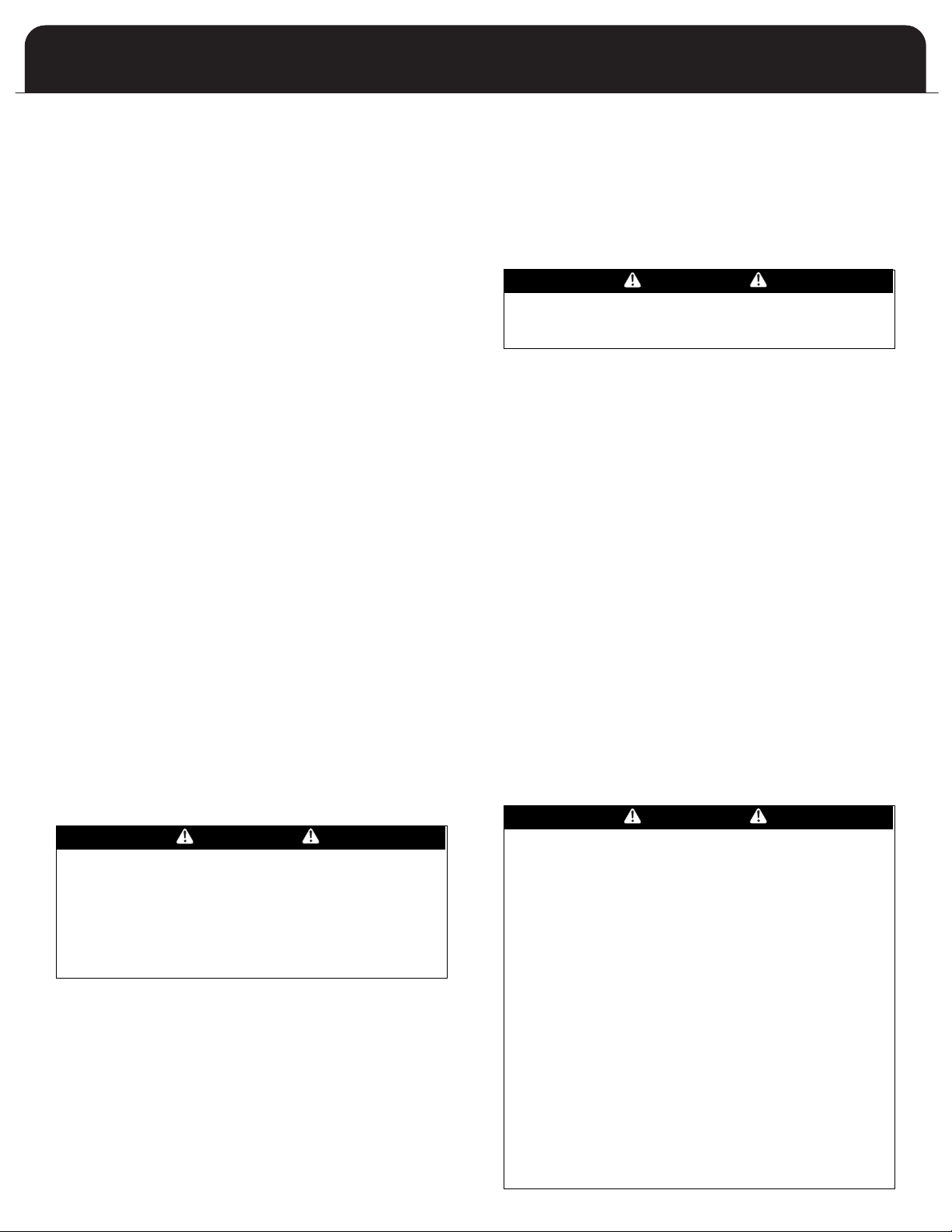
INDUCER ROTATION STEPS ON 70-3, 70-4, 85-3, 85-4,
100-3, 100-4, 100-5, 115-5 and 135-5 (See Figure 4A
below for Right Exhaust, Figure 4B below for Left
exhaust)
1. Ensure all power to the furnace is disconnected.
2. Disconnect inducer wiring and pressure switch tubing.
3. Remove four screws securing inducer plate to flue box
cover plate.
4. Place inducer plate and gasket in desired position and
locate mounting holes required. NOTE: INDUCER PLATE
AND GASKET MUST BOTH BE ROTATED.
NOTE: Any holes not concealed by the inducer gasket
require the use of screws to plug the holes.
5. Secure inducer plate to flue box cover using four screws in
the correct mounting position.
6. Carefully remove side panel knockout corresponding to the
venting application and install knockout underneath top
panel using two screws (field supplied).
7. In the event of a right hand discharge inducer application,
the pressure switch will have to be relocated to the
underside of the top panel (see Figure 4A below ) using
existing holes in top panel. The pressure switch tubing will
have to be cut to the length listed in Table 4 on page 10 if
inducer is mounted in right hand configuration.
8. Connect inducer wiring and pressure switch tubing to the
inducer housing.
FIGURE 4A: RIGHT INDUCER POSITION
Inducer Plate mounting screws (all models except 35-2, 50-3)
FIGURE 4B: LEFT INDUCER POSITION
9

WARM AIR FURNACE
OFF
ON
C2
C3
C1
OFF
ON
C2
C3
C1
OFF
ON
C2
C3
C1
C2
C3
OFF
ON
C2
C3
C1
C2
C3
C1
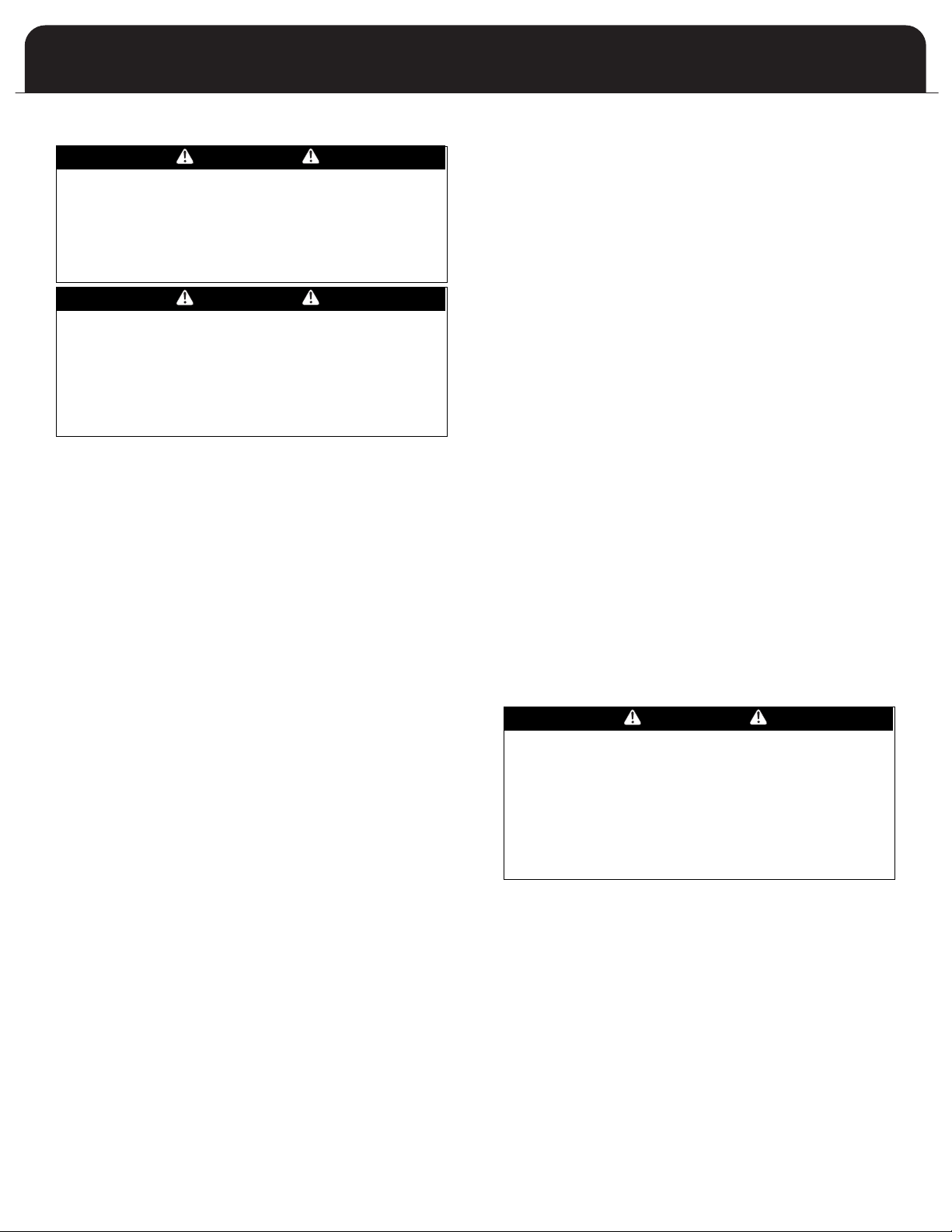
NDUCER ROTATION STEPS ON 35-2, 50-3 (See Figures
I
5A and 5B below)
. Ensure all power to the furnace is disconnected.
1
2. Disconnect inducer wiring and pressure switch tubing.
. Remove four screws securing inducer and inducer plate
3
to flue box cover plate. (see figure 4A on page 9)
4. Place inducer plate and gasket in desired position and
locate mounting holes required. NOTE: INDUCER PLATE
ND GASKET MUST BOTH BE ROTATED.
A
NOTE: Any holes not concealed by the inducer gasket
require the use of screws to plug the holes.
5. Secure inducer and inducer plate to flue box cover using
four screws in the correct mounting position.
6. Carefully remove side panel knockout corresponding to
the venting application and install cover (part #30763)
underneath top panel using two screws (field supplied).
In the event of a right hand discharge inucer application,
the pressure switch will have to be relocated to the
underside of the top panel. The pressure switch tubing
will have to be cut to the length listed in Table 4 (below)
if inducer is mounted in right hand configuration.
7. Reconnect inducer wiring and pressure switch tubing to
the inducer
FIGURE 5A: LEFT INDUCER POSITION (35-2, 50-3)
ENT CONNECTOR
V
The furnace may be vented with a listed single wall or
ype B double wall vent connector to a B-Vent or lined
T
masonry chimney. Most United States jurisdictions require a
minimum 28-gauge galvanized single wall vent connector.
Most Canadian jurisdictions require the vent connector to
have corrosion resistance equivalent to 24-gauge
alvanized sheet metal.
g
Observe the rules concerning clearance to combustibles.
he vent connector must be readily accessible for
T
inspection, cleaning or replacement.
Keep the vent connector as short as possible by locating the
urnace as close as practical to the vent or chimney. Avoid
f
unnecessary turns or bends that create resistance to the
flow of the vent gases. Fittings such as elbows add
resistance to the vent connector.
Use Type B vent connectors in attics, crawl spaces, or other
cold areas. Install thimbles that meet clearance to
combustibles requirements and local code requirements if
the vent connector must pass through a wall or partition
constructed of combustible material. The preferred method
to join vent connectors to a vent or chimney is by individual
connections. If two vent connectors must be joined before
the vent or chimney, use a correctly sized wye or tee-wye
fitting as close to the vent or chimney as practical.
All furnace collars are 4 inch. When the United States ANSI
Z223.1 / NFPA 54 or Canadian B149 venting tables specify
the use of 3 inch venting, use a 4 to 3 reducer at the furnace
collar. When the venting tables specify the use of 5inch
venting, use a 5 to 4 reducer at the furnace collar.
Secure all single wall vent connector segments together
with a minimum of three sheet metal screws per joint.
Secure the vent connector to the furnace collar with a
minimum of three sheet metal screws. Type B vent
connectors do not require sheet metal screws since they
have their own locking system.
FIGURE 5B: RIGHT INDUCER POSITION (35-2, 50-3)
TABLE 4: PRESSURE SWITCH TUBING LENGTH FOR
RIGHT INDUCER POSITION (IN INCHES)
35-2
50-3
70-3
70-4
85-3
12 1/2” 12 1/2” 13 1/2” 13 1/2” 13 1/2” 13 1/2”
100-3
100-4
100-5
115-5 135-5
13 1/2” 13 1/2” 13 1/2” 13 1/2” 13 1/2”
85-4
10

MODEL F80A
R
IDGE
1
0 FT.
RAIN TIGHT
FLASHING
1
" MIN.
C
LEARANCE
VENT CAP
5" MIN.
B-1 VENT
RIGID OR
FLEXIBLE
B-1 VENT
ADAPTER
SLOPE UP MIN. 1/4" PER FT.
1" MIN. CLEARANCE
TO COMBUSTIBLES
2 FT.
MIN
3 FT.
MIN
Figure 8: Vent Termination
RIDGE
10 FT.
2 FT.
MIN
3 FT.
MIN
ENT TERMINATION
V
Terminate all vertical vents with a listed vent cap or roof
ssembly unless local codes require otherwise. Locate the
a
termination in an area free of positive pressure or wind
eddies. Eddies may occur when wind swirls over roof peaks.
They can cause downdrafts and interfere with normal vent
operation.
Some manufactured vent caps are resistant to wind and
eddies; their use is recommended.
he vent termination must be a minimum of 5 feet above
T
the highest gas appliance connection. The vent must extend
a minimum of 3 feet above the point that it passes through
the roof. The vent termination must be a minimum of 2 feet
higher than any part of the building horizontally within 10
feet of the vent.
FIGURE 6: VENT TERMINATION
EDICATED VENTING
D
Figure 7 (below) shows a good method to permit dedicated
enting making use of B-Vent within a masonry chimney.
v
When using this method, provide support for the B-Vent.
MPORTANT: maintain at least 1-inch clearance between the
I
B-Vent and the chimney tile or chimney. This will help
prevent the formation of condensation.
FIGURE 7: DEDICATED VENTING
FAILURE TO PROPERLY TERMINATE THE VENT OR
CHIMNEY SYSTEMS COULD ALLOW COMBUSTION
PRODUCTS TO COLLECT INSIDE THE BUILDING CAUSING
CAUTION
PERSONAL INJURY OR DEATH.
11

XISTING VENT CONSIDERATIONS
E
If this furnace is to replace a Category I type furnace
onnected to a chimney serving other appliances, steps must
c
be taken to ensure that this furnace and the remaining
appliances will vent properly after the removal of the existing
furnace. There is a chance that the existing chimney will be too
large.
Check the size of the existing vent or chimney. It should be
sized as though this is a new installation. If it is not, undertake
remedies to correct the size.
Check the condition of the existing vent or chimney. Examine
vent or chimney cleanouts to make sure that they remain
tightly closed when not in use. Ensure that the vent or
chimney passageway is clear and free from obstructions. Look
for evidence of condensation damage or deterioration in the
vent or chimney. Either of these conditions indicates an
inadequate vent. Missing mortar in the top few courses of
brick in a masonry chimney is a definite sign of condensation
damage.
If the vent or chimney is found to be damaged or inadequate,
it must be repaired or replaced. The repaired or replacement
vent or chimney must meet the standards prescribed in ANSI
Z223.1 National Fuel Gas Code (NEPA 54), in the United States
or CAN/CSA-B149, Natural Gas and Propane Installation Code
in Canada.
When the new furnace is connected to a common vent, the
new furnace and the other appliances connected to the
common vent must be tested individually following these
steps:
1. Permanently seal any unused openings into the common
vent system.
2. Visually inspect the venting system for proper size and
horizontal pitch and determine that there is no blockage,
restriction, leakage, corrosion, collapsed materials such as
fallen bricks, or any other deficiency that could lead to an
unsafe condition.
3. Insofar as practical, duplicate winter operating conditions
such as closing all windows and doors in the building. If the
remaining appliances are in a mechanical room, close the
door to the room.
Close the fireplace dampers if any.
4.
5. Turn on any appliances that exhaust air to the outdoors on
maximum speed. This would include clothes dryers, range
hoods, bathroom fans, etc. Attic fans or other fans used
only in summer should be exempted from the test.
6. Follow the lighting instructions of the appliance being
tested and turn it on to continuous operation.
7. For appliances equipped with draft hoods, test for spillage
at the draft hood relief opening after 5 minutes of main
burner operation. Detect for spillage using a match flame,
taper (candle), or the smoke from a cigarette, cigar or pipe.
8.
After it has been proven that each appliance to remain
connected to the common venting system properly vents
when tested as listed above, return the windows, doors,
fireplace dampers, appliances, etc. to the condition they
were in prior to the test.
9. If improper venting is observed during any of the tests, the
common venting system must be resized. In the United
States, refer to the latest ANSI Z223.1 National Fuel Gas
Code (NEP
I furnaces. In Canada, refer to the latest addition of
CAN/CSA-B149, Natural Gas and Propane Installation Code.
A 54), or AGA-GAMA V
enting Tables for Category
WARM AIR FURNACE
AS SUPPLY
G
WARNING
HIS FURNACE IS FACTORY EQUIPPED TO BURN NATURAL
T
AS ONLY.
G
CONVERSION TO L.P. GAS REQUIRES SPECIAL KIT No.
30482.
FAILURE TO USE THE PROPER CONVERSION KIT CAN
CAUSE FIRE, EXPLOSION, CARBON MONOXIDE
POISONING, PROPERTY DAMAGE, PERSONAL INJURY OR
OSS OF LIFE.
L
CAUTION
CONVERSION OF THIS FURNACE REQUIRES SPECIALIZED
EQUIPMENT. A TRAINED AND QUALIFIED INSTALLER,
SERVICE AGENCY OR GAS SUPPLIER MUST COMPLETE
CONVERSION.
CAUTION
CONNECT THIS FURNACE ONLY TO GAS SUPPLIED BY A
COMMERCIAL UTILITY OR SUPPLIER. PRIVATE GAS WELLS
DO NOT GENERALLY PROVIDE GAS WITH CONSISTENT,
UNIFORM AND PREDICTABLE HEATING VALUES AND
DENSITIES. MANY NONCOMMERCIAL WELLS CONTAIN
IMPURITIES SUCH AS SULPHUR, WHICH MAY DAMAGE
THE FURNACE. THIS FURNACE CANNOT OPERATE
PROPERLY OR SAFELY USING FUELS OUTSIDE NORMAL
COMMERCIAL STANDARDS.
GAS PIPING
In the United States, the gas piping should be installed in
accordance with ANSI Z223.1 / NFPA 54 and any local codes.
In Canada, the gas piping should be installed in accordance
with CAN/CSA-B149, and in accordance with any local codes.
The gas piping may enter the furnace from either side.
Install a BMI ground joint union between the gas valve and
the side panel to allow easy removal of the burner for
service purposes.
IMPORTANT: ALWAYS USE A BACKUP WRENCH TO PREVENT
TWISTING OF THE CONTROL ASSEMBL
ANY STRAINS ON THE GAS VAL
POSITIONING OF THE ORIFICES RELATIVE TO THE BURNERS.
THIS COULD RESULT IN FAULTY BURNER OPERATION.
Install a manual gas shutoff valve and dirt pocket as close to
the furnace as possible. Some local codes call for the manual
gas shutof
floor level to prevent tampering by small children. Ensure
that the valve is readily accessible.
If local codes allow the use of a flexible gas appliance
connector, always use a new listed connector. Do not use a
connector which has previously serviced another gas
appliance.
f valve to be located between 4 to 5 feet above
Y AND GAS VALVE.
VE CAN AFFECT
12

MODEL F80A
CAUTION
NSURE THAT THE MANUAL SHUTOFF VALVE AND GAS
E
VALVE ARE NOT SUBJECTED TO HIGH PRESSURES.
DISCONNECT THE MANUAL SHUTOFF VALVE AND GAS
VALVE DURING ANY PRESSURE TESTING THAT EXCEEDS
1/2 P.S.I.G. (3.45 KPA
he natural gas inlet supply pressure should be 5 to 7 inches
T
water column (w.c.), 7 inches w.c. is recommended.
The L.P. gas inlet supply pressure should be 11 to 14 inches
.c., 12 inches w.c. is recommended.
w
hese pressures must be maintained while all other gas fired
T
appliances are operating at maximum conditions.
Do not exceed 14 inches w.c. inlet pressure with LP. Do not
exceed 10.5 inches w.c. inlet pressure with NG.
The gas valve has an adjustable internal regulator for
controlling burner manifold pressure. Burner manifold
pressure is listed on the furnace rating plate.
LEAK TESTING
All new gas piping installations should be pressure tested as
specified by CAN/CGA-B149 or NFPA 54 ANSI Z223.1 or
ANSI/NFPA 58, Standard for the Storage and Handling of
Liquefied Petroleum Gases.
Gas piping that has not been pressure tested, from the
manual shutoff valve to the furnace gas valve for example,
should be leak tested using an electronic combustible gas
detector, a commercially prepared leak detector such as Gas
Leak Detector® or Search®, or other locally approved
method. A leak detector solution can be prepared by mixing
a small quantity of dish detergent with water and daubing it
onto the gas piping and connections.
PURGING GAS LINES
NEVER PURGE A GAS LINE INTO THE COMBUSTION
CHAMBER.
NEVER USE A MATCH, T
OR ANY OTHER IGNITION SOURCE TO CHECK FOR LEAKS
IN A GAS LINE.
AILURE TO ADHERE TO THIS WARNING CAN CAUSE A
F
FIRE OR EXPLOSION RESULTING IN PROPER
PERSONAL INJURY, OR LOSS OF LIFE.
CONVER
SIONS
HIGH ALTITUDE
In the United States, the modifications for high altitude are
based on a 4 percent reduction of input capacity for every
1000 feet above sea level. Table 4 on page 14 illustrates the
impact of altitude for selected elevations. Ratings shown
apply to the highest elevation in range.
Consult with local fuel suppliers or authorities to determine
local regulations or customs.
In Canada, the furnace may be converted for high altitude
(2000 - 4500 feet) by changing the burner orifices. Use Kit No.
30552. The kit contains both natural gas and L.P. gas orifices;
able 5 on page 14. *
see T
for LP.
).
WARNING
APER, CIGARETTE LIGHTER, FLAME
TY DAMAGE,
Model F80A035 is not appr
oved
ATURAL TO L.P. GAS
N
This series furnace is manufactured as a natural gas (sea level)
ppliance. It may be converted to L.P. gas with the use of Kit
a
No. 30482 (contact manufacturer for availability). The kit
contains the orifices needed for all models, the regulator
spring for the gas valve, and a label to affix adjacent to the
appliance rating plate to alert subsequent service technicians
f the conversion.
o
L.P. TO NATURAL GAS
lthough the furnace is manufactured initially as a natural gas
A
appliance, if after an L.P. Gas conversion it becomes necessary
to convert back to natural gas, and if the original parts are
unavailable, Kit No. 30551 may be purchased. It is similar in
nature and content to the L.P. Gas conversion kit.
CONVERSION STEPS
To convert from sea level to high altitude, from natural gas to
L.P. gas, or from L.P. gas to natural gas, follow these steps:
Turn off gas supply to the furnace if applicable.
1. Shut off electrical power to the furnace if applicable.
2. Remove the upper front door to expose the gas train and
burner assembly.
3. Unfasten the ground joint union between the gas valve and
gas supply piping if applicable.
4. Unfasten the burner manifold pipe from the burner
assembly. It is held in place by 2 screws on either end of the
manifold pipe.
5. Remove the existing orifices with a 7/16 inch socket, box or
openend wrench. Install the replacement orifices. The
orifice spuds are brass, and do not normally require pipe
dope. A light grease may be used to lubricate the threads.
The orifice spuds have tapered threads; do not overtighten
them.
If completing a fuel conversion, remove the protective
screw cap from the gas valve regulator adjustment. Remove
the regulator adjustment screw by turning it
counterclockwise. Remove the existing regulator spring.
6. Install the new regulator spring. NOTE: If converting the
White-Rodgers gas valve, the regulator spring is tapered.
The tapered end (small end) is inserted back into the gas
valve regulator adjustment cavity.
Reinstall the adjustment. Give it 3 full clockwise turns
initially
7. Reinstall the burner manifold pipe assembly following steps
4, 5, and 6 in reverse order.
If, in all other respects the furnace is ready to be fired,
continue with the installation. If not, complete the
remainder of the installation then return to these steps
before starting the Startup & Setup section.
. Do not reinstall the protective screw cap yet.
13

TABLE 3: HIGH ALTITUDE SPECIFICATIONS - CANADA
MODEL
Input x
1000
ALTITUDE
Feet
INPUT
BTU/hr
OUT
PUT
BTU/hr
NAT.
ORIFICE
L.P.
ORIFICE QTY.
2
3
4
5
6
7
8
0 - 2000 35,000 28,000 1.95 m m 1.20 mm
35
2000 - 4500 31,500 25,200 1.90 mm 1.15 mm
0 - 2000 50,000 40,000 1.9 5 mm 1.20 m m
50
2000 - 4500 45,000 36,000 1.90 mm 1.15 mm
0 - 2000 68,000 54,400 1.9 5 mm 1.20 m m
70
2000 - 4500 61,200 48,960 1.90 mm 1.15 mm
0 - 2000 85,000 68,000 1.9 5 mm 1.20 m m
85
2000 - 4500 76,500 61,200 1.90 mm 1.15 mm
0 - 2000 100,000 80,000 1.95 mm 1 .20 mm
100
2000 - 4500 90,000 72,000 1.90 mm 1.15 mm
0 - 2000 115,000 92,000 1.95 mm 1.20 mm
115
2000 - 4500 103,500 82,800 1.90 mm 1.15 mm
0 - 2000 135,000 108,000 1.95 mm 1.20 mm
135
2000 - 4500 121,500 97,200 1 .90 mm 1.15 mm
Q
TY.
2
2
3
4
5
6
7
8
6
7
8
0 - 2000 100,000 80,000 1.95 mm 1.20 mm
100
2000 - 4500 90,000 72,000 1.90 mm 1.15 mm
0 - 2000 115,000 92,000 1.95 mm 1.20 mm
115
2000 - 4500 103,500 82,800 1.90 mm 1.15 mm
TABLE 4: HIGH ALTITUDE SPECIFICATIONS - UNITED STATES
MODEL
Input x
1000
A
LTITUDE
F
eet
I
NPUT
B
TU/hr
N
AT.
O
RIFICE
L
.P.
O
RIFICE
0 - 2000 35,000 28,000 1 .95 mm 1.20 mm
2000 - 3000 30,800 24,640 1.83 mm 1.13 mm
3000 - 4000 29,400 23,520 1.79 mm 1.10 mm
4000 - 5000 28,000 22,400 1.74 mm 1.07 mm
35
5000 - 6000 26,600 21280 1.70 mm 1.05 mm
0 - 2000 50,000 40,000 1.95 m m 1.20 mm
2000 - 3000 44,000 35,200 1.83 mm 1.13 mm
3000 - 4000 42,000 33,600 1.79 mm 1.10 mm
4000 - 5000 40,000 32,000 1.74 mm 1.07 mm
50
5000 - 6000 38,000 30,400 1.70 mm 1.05 mm
0 - 2000 68,000 54,400 1.95 mm 1 .20 mm
2000 - 3000 59,840 47,872 1.83 mm 1.13 mm
3000 - 4000 57,120 45,696 1.79 mm 1.10 mm
4000 - 5000 54,400 43,520 1.74 mm 1.07 mm
70
5000 - 6000 51,680 41,344 1.70 mm 1.05 mm
0 - 2000 85,000 68,000 1.95 mm 1 .20 mm
2
000 - 3000 74,800 59,840 1.83 mm 1.13 mm
3
000 - 4000 71,400 57,120 1.79 mm 1.10 mm
4000 - 5000 68,000 54,400 1.74 mm 1.07 mm
8
5
5000 - 6000 64,600 51,680 1.70 mm 1.05 mm
0 - 2000 100,000 80,000 1.95 mm 1.20 mm
2000 - 3000 88,000 70,400 1.83 mm 1.13 mm
3000 - 4000 84,000 67,200 1.79 mm 1.10 mm
4000 - 5000 80,000 64,000 1.74 mm 1.07 mm
100
5000 - 6000 76,000 60,800 1.70 mm 1.05 mm
0 - 2000 115,000 92,000 1.95 mm 1.20 mm
2000 - 3000 101,200 80,960 1 .83 mm 1.13 mm
3000 - 4000 96,600 77,280 1.79 mm 1.10 mm
4000 - 5000 92,000 73,600 1.74 mm 1.07 mm
115
5000 - 6000 87,400 69,920 1.70 mm 1.05 mm
O
UT
PUT
BTU/hr
0
- 2000 135,000 108,000 1.95 mm 1.20 mm
1
35
2
000 - 4500 121,500 97,200 1.90 mm 1.15 mm
0 - 2000 135,000 108,000 1.95 mm 1.20 mm
2000 - 3000 118,800 95,040 1.83 mm 1.13 mm
3000 - 4000 113,400 90,720 1.79 mm 1.10 mm
4000 - 5000 108,000 86,400 1.74 mm 1.07 mm
135
5000 - 6000 102,600 82,080 1.70 mm 1.05 mm
E
X
AIRFLOW - CFM
T
E
RN ALSTATIC PRESURE - Inches
w.c
.
M
ODEL FAN
HP
SPEED
0
.1
0 0.20 0.30 0.40 0.50 0.60
H
IGH 8 92 900 910 907 899 884
ME D- HI 7 21 730 75 1 763 769 757
MED-LO 5 89 603 614 625 632 632
3
5-2
10-
4
DD
1/4
LO W 519 527 539 547 556 551
HIGH 1 512 1496 1448 1406 1337 1272
ME D- HI 1 322 1311 1288 1249 1208 1140
M
ED-LO 9 80 971 963 954 929 896
50-3
1
0-7
DD
1/3
LO W 754 746 738 735 723 690
HIGH 1 688 1643 1589 1527 1465 1389
M
ED- HI 1 415 1401 1386 1356 1306 1250
MED-LO 9 88 992 1008 1008 1001 970
70-3
10-8
DD
1/3
LO W 721 736 763 768 765 765
HIGH 1 710 1681 1655 1612 1559 1485
ME D- HI 1 384 1398 1405 1401 1387 1364
MED-LO 9 26 948 975 990 980 964
70-4
10-9
D
D
1/2
LO W 714 728 757 763 760 687
HIGH 1 624 1608 1582 1533 1483 1409
MED HI 1 407 1399 1388 1355 1313 1254
MEDLO 990 995 999 1005 992 968
85-3
10-8
DD
1/3
LO W 742 752 766 774 774 769
HIGH 2 106 2083 2028 1943 1862 1753
ME D- HI 1 856 1840 1816 1777 1705 1620
MED-LO 1 577 1587 1600 1580 1530 1465
85-4
2Side
Returns
2Side
Returns
10-10
DD
1/2
LO W 1325 1342 1368 1386 1371 1314
HIGH 1 766 1747 1738 1711 1653 1602
ME D- HI 1 440 1444 1448 1459 1434 1397
MED-LO 9 88 1008 1027 1042 1060 1005
100-4
10-10
DD
1/2
LO W 768 780 794 747 704 664
HIGH 2 195 2168 2102 2028 1950 1846
ME D- HI 1 915 1900 1892 1854 1785 1713
MED-LO 1 610 1621 1621 1594 1612 1550
100-5
1Side
Return
12-10
DD
3/4
LO W 1357 1372 1401 1419 1394 1360
HIGH 2 399 2359 2290 2219 2146 2070
ME D- HI 2 175 2116 2070 2007 1959 1892
MED-LO 1 991 1959 1909 1875 1841 1788
100-5
2Side
Returns
12-10
DD
3/4
LO W 1671 1636 1624 1587 1537 1498
HIGH 2 413 2334 2280 2197 2126 2051
ME D- HI 2 253 2197 2111 2051 1990 1911
MED-LO 2 140 2096 2021 1959 1895 1845
115-5
2Side
Returns
12-10
DD
3/4
LO W 1820 1789 1735 1679 1644 1597
HIGH 2 100 2082 2054 2012 1954 1910
ME D- HI 1 782 1763 1738 1746 1704 1670
MED-LO 1 433 1437 1444 1440 1422 1411
115-5
Bottom
&Side
Return
12-10
DD
3/4
LO W 1231 1234 1238 1238 1237 1233
HIGH 2550 2468 2403 2323 2239 2167
MED-HI 2309 2239 2182 2108 2047 1984
MED-LO 2182 2123 2077 2015 1968 1902
135-5
2Side
Returns
Returns
12-10
DD
3/4
LOW
LOW
1833 1800 1779 1723 1653 1618
HIGH 2135 2128 2094 2060 2019 1955
MED-HI 1822 1807 1800 1791 1768 1736
MED-LO 1473 1482 1496 1509 1492 1468
135-5
Bottom
&Side
12 x
10
DD
3/4
1241 1258 1270 1278 1270 1265
ABLE 4: HIGH ALTITUDE SPECIFICATIONS - USA
T
T
ABLE 5: HIGH AL
TITUDE SPECIFICATIONS - CANADA
WARM AIR FURNACE
ABLE 6: AIRFLOW SPECIFICATIONS
T
14

MODEL F80A
ETTING THE MANIFOLD (Outlet) GAS PRESSURE
S
(F92-1003 36G Valve Pressure Check Kit)
1. Shut off the gas upstream of valve and move valve
switch to “OFF”.
2. Using the 3/32 inch hex wrench that is included in the
alve pressure check kit, rotate outlet pressure tap
v
crew one revolution counter-clockwise.
s
. Attach the 5/16 inch hose that is included in the valve
3
pressure check kit to the outlet pressure boss of the
valve. Hose should overlap boss 3/8 inch.
4. Connect 5/16 inch side of connector that is included in
the valve pressure check kit to the hose on outlet boss.
onnect 1/4 inch side of connector to manometer hose.
C
5. Turn on gas supply to valve and move valve switch to
the “ON” position.
6. Turn on furnace following manufacturer’s instructions.
7. Using a leak detection solution check for leaks at hose
connections.
DANGER
SHUT OFF GAS AND FIX LEAKS IMMEDIATELY BEFORE
PROCEEDING.
DANGER
TRAINED, QUALIFIED TECHNICIAN MUST DO ALL
A
REGULATOR ADJUSTMENTS. IMPROPER MODIFICATIONS
OR ADJUSTMENTS CAN RESULT IN FIRE OR EXPLOSION
CAUSING PROPERTY DAMAGE, SEVERE PERSONAL
INJURY OR LOSS OF LIFE.
In some circumstances, high inlet pressure can be remedied
with the use of an inline appliance regulator. If an inline
appliance regulator is used, ensure that it has the capacity
o adequately handle the gas volume required by the
t
furnace and any other appliances receiving gas from the
header serving the furnace.
Figure 8: White-Rodgers Gas valve
Outlet
Pressure
Boss
Regulator
Vent
8. Read manometer. This reading is the system
outlet/supply pressure.
9. Follow manufacturer’s instructions to adjust outlet
/supply pressure, if necessary.
10. Shut off gas supply upstream of valve and move the
valve switch to the “OFF” position.
11. Remove manometer and hose from outlet boss.
12. Turn outlet pressure tap screw clockwise to seal the
pressure point using the supplied hex wrench. Tighten
to 13 in-lbs. minimum.
13. Turn on gas supply to valve and move valve switch to
the “ON” position.
14. Turn on furnace following manufacturer’s instructions.
15. Using leak detection solution check for leaks at outlet
pressure tap. Shut off gas and fix all leaks immediately
before proceeding.
If problems were encountered with obtaining enough
pressure on the manifold, first examine the gas piping
system to ensure that it is correctly sized. Pipe sizing is
specified in ANSI Z223.1 / NFPA 54 in the U.S., or the B148
Natural Gas and Propane Installation Code in Canada.
CHECKING THE SUPPLY (Inlet) GAS PRESSURE (F92-1003
Valve Pressure Check Kit)
Check inlet pressure following steps 1 through 15 above
using the inlet/supply pressure tap boss.
Inlet
Pressure
Boss
(Optional)
Connection
Terminals
On/Off Switch
Regulator
Adjustment
ELECTRICAL SPECIFICATIONS
Before proceeding with the electrical connections, ensure
that the available electrical supply is compatible with the
voltage, frequency, and phase listed on the appliance rating
plate.
All furnaces are rated 120 VAC, 60 Hz, 1 phase. The
amperage rating is indicated on the furnace rating plate.
Each furnace requires a dedicated overcurrent device either
a circuit breaker or a Type D, time delay fuse. It is
permissible to connect furnace accessories such as
humidifier transformers, condensate pumps and electronic
air cleaners. If adding accessory equipment to the furnace
circuit, ensure that the combined amperages listed on the
appliance rating plates do not exceed the rating of the over
current device.
DANGER
SHUT OFF ELECTRICAL POWER AT THE FUSE BOX OR
SERVICE PANEL BEFORE MAKING ANY ELECTRICAL
CONNECTIONS. FAILURE TO DO SO CAN CAUSE
ELECTRICAL SHOCK RESUL
LOSS OF LIFE.
TING IN PERSONAL INJUR
Y OR
15

DANGER
Figure 13: Isolation Relay
THERMOSTAT
COOLING
CONTACTOR
FAN
RELAY
HEATING RELAY
24V
115V
R
G
Y
W
Y
G
W
HE FURNACE CABINET MUST HAVE AN UNINTERRUPTED
T
GROUND.
A GROUND WIRE IS PROVIDED IN THE ELECTRICAL
UNCTION BOX.
J
DO NOT USE GAS PIPING AS A GROUND.
FAILING TO GROUND THE FURNACE PROPERLY CAN
RESULT IN ELECTRIC SHOCK RESULTING IN PERSONAL
INJURY OR DEATH.
In the United States, all electrical work must be in accordance
with the latest edition of the National Electrical Code, ANSI /
NFPA 70, in Canada, all electrical work must be in accordance
with the latest edition of CSA-C22.1, Canadian Electrical Code
Part 1, and any applicable local code.
Although a suitably located circuit breaker may serve as a
service switch, a separate service switch is recommended.
A separate in service switch is necessary if the circuit breaker
is in a location where accessing it would require getting close
to the furnace, or if the furnace is located between the main
electrical panel and the entry to the furnace room. The
furnace switch (service switch) should be clearly labeled and
installed in a location where it is not likely to be mistaken as
being a light switch or similar control.
FURNACE CONNECTION
120V: The furnace is shipped fully wired except for the
connections to the house wiring. The furnace power
connections are made in a junction box inside the blower
compartment. The junction box is factory installed on the left
hand side however, it may be moved to the right hand side.
The junction box contains a BLACK wire to be connected with
L1 (hot), a WHITE wire to be connected with L2, the Neutral,
and a GREEN wire to be connected to the ground.
Use good quality wire nuts; e.g. Marrette® connectors, Ideal®
wire nuts, etc.
IMPORTANT: USE COPPER CONDUCTORS ONLY
If the junction box must be moved to the right hand side:
1. Unfasten the junction box from the left hand side.
2. Remove the right side panel knockout.
3. Remove the junction box cover hook screw and reinstall it
on the opposite side of the box.
4. Fasten the junction box to the right hand panel.
NOTE: L1 (hot) and L2 (Neutral) polarity must be observed
when making field connections to the furnace. The ignition
control may not sense flame if L1 and L2 are reversed. The
ground is also essential.
NOTE: The furnace shall be installed so the electrical
components are protected from water.
THIS FURNACE IS EQUIPPED WITH A BLOWER DOOR
SAFETY SWITCH. DO NOT DISABLE THIS SWITCH. FAILURE
TO FOLLOW THIS WARNING CAN RESULT IN ELECTRICAL
SHOCK, PERSONAL INJUR
ELECTRICAL WIRING AND COMPONENTS MUST BE PROTECTED
FROM MOISTURE, INCLUDING WATER AND CONDENSATE.
WARNING
Y
CAUTION
, OR LOSS OF LIFE.
16
WARM AIR FURNACE
OW VOLTAGE WIRING
L
The low voltage terminals are located on the control board
ounted to the blower assembly; see Figure 11 on page 19.
m
The furnace is prewired for air conditioning. Insert the
thermostat and air conditioner contactor low voltage wiring
through the bushing provided in the side panel. Route the
ontrol wiring through the blower compartment to the
c
24 volt terminal screws.
THERMOSTAT
The room thermostat must be compatible with the integrated
control in the furnace. Electromechanical thermostats should
be rated 30 V / 1.5 amps.
Most electronic or microprocessor based thermostats except
those with "current robbing" circuits should work
satisfactorily. Consult the instructions of the thermostat
manufacturer for technical and installation details.
Most compatibility problems can be overcome by the use of
an isolation relay. The isolation relay should be SPST with a 24volt coil. The switch ratings should be a minimum of 0.5 amps;
see figure 9 below.
The thermostat and control wiring should be a minimum of 18
AWG copper. Excessive lengths of wire may result in enough
voltage drop to impair the proper functioning of the furnace.
For thermostat wires in excess of 25 feet, use 16 AWG; 50 feet,
use 14 AWG.
Figure 9: Isolation relay
THERMOSTAT LOCATION
The thermostat should be located approximately 5 feet above
the floor, on an inside wall where there is good natural air
circulation, and where the thermostat will be exposed to
average room temperatures. Avoid locations where the
thermostat will be exposed to cold drafts, heat from nearby
lamps or appliances, exposure to sunlight, heat from inside
wall stacks, etc.
THERMOSTAT HEAT ANTICIPATOR SETTING:
0.45 AMP (White-Rodgers)
See page 21 for information on connecting optional
accessories such as electronic air cleaners and power
humidifiers.

MODEL F80A
TART UP PROCEDURES
S
This furnace is equipped with a hot surface ignition (HSI) device.
ach time that the room thermostat calls for heat, the HSI lights
E
the main burners directly. See the lighting instructions on the
furnace.
TO START THE FURNACE:
1. Remove the burner compartment access door.
. Shut off the electrical power to the furnace and set the
2
room thermostat to its lowest setting.
3. Ensure that the ignition system control switch on the White-
odgers 36G22 gas valve is in the “ON” position.
R
4. Replace the burner compartment access door.
5. Restore electrical power to the furnace.
6. Set the room thermostat to a point above room
temperature to light the furnace.
7. After the burners are lit, set the room thermostat to the
desired temperature.
TO SHUT DOWN THE FURNACE:
1. Set the room thermostat to its lowest setting.
2. Remove the burner compartment access door.
3. The ignition system control switch on the White-Rodgers
36G22 gas valve may be switched to the “OFF” position.
4. The furnace appliance shutoff valve may be closed if
desired.
WARNING
SHOULD OVER HEATING OCCUR, OR THE GAS BURNERS FAIL
TO SHUT OFF, CLOSE THE MANUAL GAS VALVE FOR THE
FURNACE BEFORE SHUTTING OFF THE ELECTRICAL POWER
TO THE FURNACE. FAILURE TO DO SO CAN CAUSE AN
EXPLOSION OR FIRE RESULTING IN PROPERTY DAMAGE,
PERSONAL INJURY OR LOSS OF LIFE.
SEQUENCE OF OPERATION
White-Rodgers 36G22 Gas Valve &
White-Rodgers 50A55-250 Integrated Furnace Control
1. Room temperature drops causing the room thermostat
heating contacts to close.
2. The induced blower begins a prepurge cycle of 15 seconds.
The pressure switch contacts close.
3.
After the prepurge period, the hot surface igniter heats up;
4.
10 seconds on a first try, maximum 14 seconds on a
subsequent retry.
5. The gas valve opens for a 7 second trial for ignition. The
gas burners light, the igniter shuts off. (See next section for
sequence of operation in the event of a flame failure).
The circulating fan begins 30 seconds after flame is sensed.
6.
7. Furnace continues to run in this state until the room
thermostat heating contacts open in response to raised
room temperature.
8. With the thermostat heating contacts open, the burner
flames extinguish immediately, the induced blower stops
after a 5 second postpurge period. The pressure switch
contacts open.
The circulating fan continues to run until timed out in 60 to
9.
180 seconds, depending on the 50A55-250 Dip Switch
settings.
equence if the furnace does not light up or
S
detect flame:
1. See steps 1 through 5 for initial operation.
2. If pressure switch contacts are closed; and have failed
to open since the last cycle, all subsequent steps will
fail to occur.
3. If the burners fail to light, or if the flame is not sensed,
the gas valve closes, and, providing that there have
been less than 5 trials for ignition, sequence returns to
equence of operation Step 4. If this was the 5th trial
s
for ignition, the ignition system goes into a 60 minute
lockout condition, and then reattempts the sequence
at Step 4.
In addition, if during the burner firing, the flame signal
is lost, the gas valve will close and the ignition
sequence will begin again at Step 4 above. If the flame
sensing signal is lost more than 5 times during a
furnace cycle, the gas valve will close, and the ignition
sequence goes into a 5 second postpurge; the induced
blower stops. The ignition system goes into a 60
minute lockout condition then reattempts the
sequence at Step 4 above.
The 60 minute lockout sequence will repeat itself
indefinitely. Lowering the room thermostat setting
below room temperature for approximately 10
seconds, or shutting off the electrical supply to the
furnace for approximately 10 seconds may interrupt
the 60 minute lockout.
4. Furnace continues to run in this state until the room
thermostat heating contacts open in response to raised
room temperature.
5. With the thermostat heating contacts open, the burner
flames extinguish immediately, the induced blower
stops after a 5 second postpurge period. Pressure
switch contacts open.
6. The circulating fan continues to run until timed out in
60 to 180 seconds, depending on the 50A55-250
Integrated Furnace Control dipswitch settings.
Additional information is available in the Troubleshooting
section that starts on page 22 of this manual.
17

HECKING FURNACE INPUT
Input
Heating Value of Gas 3600
Time in Sec. for 1 cu. ft
=
X
C
The natural gas supply pressure should be a maximum of
•
7 inches w.c. and minimum of 5 inches w.c.
The burner manifold pressure is normally set to 3.5 inches
•
w.c. for natural gas
• The input rating of the furnace is based on 1075 / BTU/cu.
t. gas with a specific gravity of 0.60
f
Since heating values for the gas vary geographically, the
ctual furnace input and output will vary accordingly.
a
For example, natural gas with a 1000 BTU / cu. ft. heating
alue will reduce the input to 93% of the rated input.
v
Natural gas with a 1100 BTU / cu. ft. heating value will
increase the input to approximately 103% of the rated
input. This is not usually a problem; however, adjustments
to compensate for this can be made by minor adjustments
to the burner manifold pressure or by changing the burner
orifice size.
In the previous example where the heating value of the gas
is 1100 BTU / cu. ft., the burner manifold pressure can be
reduced .3% to 3.4% w.c. which is within the ±0.30 inches
w.c. specification to bring the input into compliance. Refer
also to Setting the Gas Pressure, and contact the fuel
supplier for specific gas heating content values.
If using a gas meter to check the furnace input, be sure that
all gas fired appliances other than the furnace are off
during the test.
Any adjustments to the burner manifold pressure should be
carried out with the use of a manometer or calibrated
magnehelic gauge. Do not adjust the gas valve pressure
regulator more than ± 0.30 inches water column.
The formula for determining the furnace input via the gas
meter test dial is:
Where:
Input is expressed in BTU / Hr.
Heating value of the gas is expressed in BTU / cubic feet
Time means time required for the test dial to indicate 1
cubic foot in seconds.
If using a gas meter with SI (metric) units:
1 cubic foot = 0.0283 cubic meters.
1 cubic meter = 35.315 cubic foot.
0.01cubic meter = 0.3531 cubic foot.
0.5 cubic meter = 1.766 cubic feet.
IMPORTANT: NEVER ADJUST THE INPUT OF THE FURNACE
TO EXCEED THE INPUT SHOWN ON THE RATING PLATE.
WARM AIR FURNACE
EMPERATURE RISE CHECK
T
When the duct system is complete and the air filter or filters
are in place, determine if the airflow is correct.
1. Insert a duct thermometer in the supply air duct. The
thermometer should be placed as close as practical to
he furnace, but out of the "line of sight" of the heat
t
exchanger (this prevents false readings owing to
radiant heat). Ensure that the thermometer location is
within the duct air stream. Avoid locations such as the
inside radius of an elbow, etc.
2. Insert a duct thermometer in the return air duct as
close to the furnace as practical. Ensure that the
hermometer location will be unaffected by humidifier
t
bypass ducts, etc. Choose a location well within the
main air stream.
3. Operate the furnace long enough to obtain steady
state conditions.
4. When the two thermometers have stabilized, usually
within 5 - 8 minutes, compare the two readings.
Subtract the return air temperature from the supply air
temperature. The difference is the temperature rise,
also called
5. Compare the measured
range shown on the rating plate.
Unless stated differently on the rating plate, the
temperature rise should normally range between 30° to
60°F or 35° to 65°F. When adjusting the temperature rise,
the ideal temperature is approximately mid-range.
If the measured
range, there is too little airflow. The airflow must be
increased by selecting a faster fan speed, removing
restrictions in the ductwork, or adding supply or return
ductwork.
If the measured
Use a lower speed tap on the multispeed motor. The blower speed is changed at the integrated furnace control.
Remove the wire from the “HEAT-H” terminal of the
50A55-20 integrated furnace control and plug in the
desired wire on the “HEAT-H” terminal. When this configuration is used, the following color codes are used: Black High Speed, Blue - Medium-High Speed, Yellow - MediumLow Speed and Red - Low Speed. The unused leads are
connected to the M1, M2 terminals on the 50A55-20 integrated furnace control.
IMPORTANT: If the heating speed and cooling speed are to
be the same, remove the cooling lead from the control,
tape it of
control "HEAT" terminal to the "COOL" terminal. UNDER
NO CIRCUMSTANCE MAY TWO MOTOR WINDINGS BE
POWERED SIMUL
The piggyback connector is used for both types of motor
wiring configuration wiring block and permanent lead, see
figure 10 below.
∆T.
∆T to the temperature rise
∆T is above the approved temperature
∆T is too low, there is too much airflow.
f, then install a "piggyback" connector from the
.
ANEOUSL
T
Y
18
Figure 10:
Piggyback
Connector
Remove blue wire
from HEA
tape it off, and
replace it with a
jumper. Connect the
black wire and
jumper to COOL.
T terminal,

MODEL F80A
SEC.SW 1SW-2
60ONON
90OFF ON
120*ON OFF
1
80OFF OFF
DIP SWITCH
HEAT "OFF" DELAY
AIRFLOW
For proper furnace operation, airflow over the heat exchanger
s of utmost importance. Insufficient airflow accelerates metal
i
atigue and failure in the heat exchanger and excessive
f
airflow promotes accelerated corrosion of the heat exchanger.
MPORTANT: Do not bypass this step of the start up
I
procedures.
CALCULATING AIRFLOW
There are circumstances where it may be desirable to know
the airflow delivery through the duct system, such as when
stimating the amount of airflow available for air condition-
e
ing. This can be done by direct measurement with electronic
or sloped manometers and velometers, or by using the formula below.
Where:
Cfm is airflow in cubic feet per minute
∆T is the temperature rise
Bonnet output is the furnace output capacity from the rating
plate.
NOTE: The bonnet output will vary directly with the input. If
the actual input is below the stated input, the output will be
reduced in the same ratio.
ADJUSTING BLOWER SPEEDS
If the blower speeds require adjusting, follow these steps:
WARNING
DISCONNECT THE ELECTRICAL SUPPLY TO THE FURNACE
BEFORE ATTEMPTING TO CHANGE THE BLOWER SPEED.
FAILURE TO DO SO COULD RESULT IN ELECTRICAL SHOCK
RESULTING IN PERSONAL INJURY OR LOSS OF LIFE.
1. Remove the blower compartment door
2. Access the motor electrical wiring.
The blower speed is changed at the integrated furnace
control. Remove the wire from the "HEAT" terminal of
the 50A55-250 integrated furnace control and plug in the
desired wire on the HEAT" terminal. When this
configuration is used, the following color codes are used:
Black - High Speed, Blue - Medium-High Speed, Yellow Medium-Low Speed, and Red - Low Speed. The unused
leads are connected to the “PARK” terminals on the
50A55-250 integrated furnace control.
IMPORTANT: If the heating speed and cooling speed are
to be the same, remove the cooling lead from the
control, tape it off, then install a “piggyback” connector
from the control “HEA
terminal. UNDER NO CIRCUMSTANCE MAY TWO MOTOR
WINDINGS BE POWERED SIMUL
3. Slide the blower assembly back into position, and
refasten with the sheet metal screws.
Reinstall the blower compartment door
4.
5. Recheck temperature rise.
NOTE: Temperature rise should always be rechecked
whenever blower speed changes are done.
T” terminal to the “COOL”
T
.
ANEOUSLY.
.
19
ETTING BLOWER "OFF"
S
TIMINGS
oth control systems allow
B
flexibility in the FAN OFF
delay function. The control
is located in the blower
compartment. Follow the
ame steps as listed in
s
Adjusting Blower Speeds to
access the control.
Figure 11: 50A55-250 Dip Switch Settings
These dip switches
control the “Blower
off” timing
HOW TO REMOVE THE BLOWER
1. Disconnect power from furnace.
2. Remove thermostat wiring from the integrated furnace
control.
3. Remove L1, Neutral and Ground connections between
the integrated furnace control and the Furnace electrical
connection junction box.
4. Remove 12 pin male molex connector from female
connection point, and ground connection from
integrated furnace control.
5. Unscrew 2 blower housing bolts located in the front
blower shroud as indicated in figure 12 below. Remove
front blower shroud from furnace.
6. Slide blower assembly towards front of furnace. Blower
is mounted on rail system, and will slide forward about
10 inches before blower is clear of rails.
HOW TO INSTALL THE BLOWER
1. Place blower into blower compartment.
2. Keep blower assembly tight to top of blower
compartment. Line up blower assembly to slide into
blower rails. Push blower assembly towards back of
furnace ensuring blower assembly is correctly placed in
blower rails. Insert blower shroud on the front of the
blower housing. Insert blower housing bolts and tighten.
3. Connect thermostat wiring to the integrated furnace
control.
4. Connect L1, Neutral and Ground connections between
the integrated furnace control and the furnace electrical
connection junction box.
5. Connect 12 pin male molex connector to female
connection point, and ground connection to the
integrated furnace control.
6. Turn on power to the furnace.
Figure 12: Blower bolts
Bolts

WARM AIR FURNACE
AINTENANCE
M
WARNING
ISCONNECT THE ELECTRICAL POWER SUPPLY TO THE
D
FURNACE BEFORE ATTEMPTING ANY MAINTENANCE.
FAILURE TO DO SO CAN CAUSE ELECTRICAL SHOCK
RESULTING IN PERSONAL INJURY OR LOSS OF LIFE.
AIR FILTER
he filter should be inspected frequently and cleaned as
T
necessary. We recommend a monthly inspection at first,
perhaps coinciding with the arrival of the monthly fuel bill as
a reminder. The frequency may be increased or decreased
depending on experience and conditions.
CAUTION
Do not operate the furnace without an air filter.
LUBRICATION
Both the induced draft blower motor and circulating fan
motor are ball bearing type motors. Neither requires routine
lubrication.
IMPORTANT: The motor bearings were prelubricated by the
motor manufacturer. Do not attempt to lubricate them.
Excess lubrication will void the warranty, shorten the service
life of the motors, and will attract the buildup of dust and
dirt.
The induced blower motor and circulating fan motor must be
cleaned on a periodic basis by a qualified service technician.
Dust buildup in the ventilation ports of the motor will cause
the motor to not dissipate heat properly resulting in reduced
service life.
VENT CONNECTOR
The exhaust venting between the furnace vent box and
chimney should be inspected periodically for sags, pitting,
evidence of leakage etc. If any of these conditions exist,
contact your installation contractor, service agency or fuel
supplier
.
WARNING
HOLES IN THE EXHAUST PIPING OR FURNACE HEAT
EXCHANGER CAN ALLOW TOXIC FUMES TO ENTER THE
HOME AND CIRCULATE THROUGH THE DUCT SYSTEM
TING IN CARBON MONOXIDE POISONING OR
RESUL
DEATH. IF LEAKS ARE FOUND IN THE FURNACE HEAT
EXCHANGER, IT MUST BE REPLACED.
PERATING TIPS
O
1. Clean air filters maximize efficiency and reduce heating
osts.
c
2. During the heating season, keep windows and doors
closed to reduce the heating load on the system.
3. Avoid excessive use of kitchen exhaust hoods and other
exhaust fans to reduce the heating load on the system.
4. Arrange the furniture and drapes so that the supply air
registers and return air grilles are unobstructed.
5. If you have a perimeter duct system, ideally, the warm air
should bathe the cold exterior walls. Avoid the use of
plastic deflectors on the supply air registers that tend to
short circuit the warm air straight into the return air
grilles. These deflectors are often the cause of cool
draughts across the floor.
6. Avoid placing heat producing appliances such as
televisions, radios, lamps, etc. in a location to influence
the thermostat.
7. Keep combustible articles at least 3 feet away from the
furnace. Do not block access for servicing the furnace.
Do not use the vent connector as a hanger for clothes or
anything else.
8. Never attempt to operate the furnace without the
blower door in place.
ANNUAL INSPECTION / SERVICE
A qualified installation contractor, service agency or fuel
supplier must inspect the furnace annually.
Your annual inspection will normally cover the following:
HEAT EXCHANGER
The heat exchanger should be inspected for corrosion. The
flue passages (heat exchanger tubes) should be free of scale
or excessive corrosion. Observe the burner flames. If there
appears to be flame distortion, check venting for blockage.
Also check for signs of inadequate combustion air supply. If
flame distortion continues after eliminating the blockage in
the venting as the cause, it may be necessary to replace the
tubular heat exchanger. The tubular heat exchanger cannot
be field cleaned. If the tubular heat exchanger is blocked by
soot or excess scale, replace it. Check NOX baffles (installed in
heat exchanger tubes) for any distortion. If distorted, replace
NOX baffles.
BURNERS
The burners should be inspected to ensure that they are free
of deterioration, dust and debris, and properly aligned with
the heat exchanger. In most cases, a simple vacuuming with a
brush attachment will adequately clean the burner assembly
and burner compartment.
CAUTION
Be careful when working on the burner assembly. The hot
surface igniter is fragile and can break easily.
The flame sensor should be inspected and cleaned with fine
steel wool or Scotch-Brite™ scrubbing pad. The wiring
connection should be checked to ensure that it is tight and
corrosion free.
NOTE: This is a critical connection. Small amounts of corrosion
can significantly increase the internal resistance of the
connection. A relatively small increase in resistance can result
in a large decrease in flame signal.
20

MODEL F80A
NDUCED BLOWER
I
The induced blower motor should be inspected and cleaned
f necessary. Clear any dust buildup from the ventilation
i
ports.
CIRCULATING FAN
The condition of the circulating fan should be checked to
ensure that it is free of excessive dust buildup, debris, etc.
The mechanical fasteners should be inspected and checked
for proper tightness and parts alignment. The motor
entilation ports should be cleaned if necessary to prevent
v
restriction to cooling by air over the motor.
ELECTRICAL
WARNING
DISCONNECT THE ELECTRICAL POWER SUPPLY TO THE
FURNACE BEFORE ATTEMPTING THIS MAINTENANCE
PROCEDURE. FAILURE TO DO SO CAN CAUSE
ELECTRICAL SHOCK RESULTING IN PERSONAL INJURY OR
LOSS OF LIFE.
All electrical connections should be examined to ensure that
they are tight and corrosion free. Repair any connections
that have become loose or corroded.
CAUTION
Label all wires prior to disconnection when servicing
controls. Wiring errors can cause improper and
dangerous operation.
Always verify proper operation after servicing.
CCESSORIES
A
FIELD SUPPLIED AND INSTALLED OPTIONAL
ACCESSORIES
ELECTRONIC AIR CLEANER
he White-Rodgers integrated furnace control has
T
provisions to supply power and control an electronic air
cleaner rated at 120vac, 1.0 amp max.
0A55-250: Line voltage for an electronic air cleaner may be
5
picked up from the "EAC-N". 120 volt power will be
available at these terminals whenever the circulating fan is
operating in the heating or cooling modes.
HUMIDIFIER/ ELECTRONIC AIR CLEANERS
The White-Rodgers integrated furnace control has
provisions to supply power and to control a line voltage
humidifier or the primary of a 120 / 24 volt humidifier step
down transformer, rated at 120vac, 1.0 amp max.
50A55-250: Line voltage for a humidifier may be picked up
from the "HUM-H" terminal and from the "HUM-N"
terminal. 120 volt power will be available at these terminals
whenever the circulating fan is operating in the heating
mode.
NOTE: All HUM (humidifier) and EAC (electronic air
cleaner) terminals are 120v. Do not directly connect
24v equipment to them.
NOTE: All furnace and furnace accessory wiring shall
conform to the temperature limitations of 63°F (35°C)
rise.
FURNACE OPERATION
The furnace should be cycled during the annual inspection
and servicing to:
1. Test all safety related controls.
2. Determine that the temperature rise falls within the
range shown on the appliance rating plate.
3. Ensure that the burner ignition is smooth and that the
flames are smooth soft blue, and not impinging on the
heat exchanger
.
21

WARM AIR FURNACE
TROUBLESHOOTING
SEQUENCE OF OPERATION: WHITE RODGERS INTEGRATED FURNACE CONTROL WITH WHITE RODGERS 36G22 GAS VALVE
APPLY POWER TO APPLIANCE
T
HERMOSTAT CALLS FOR HEAT
A
IR PROVING SWITCH PROVED OPEN?
C
OMBUSTION AIR BLOWER ON
AIR PROVING SWITCH PROVED
CLOSED
PREPURGE
HOT SURFACE IGNITER ON FOR
WARM-UP TIME
MAIN VALVE OPENS
HOT SURFACE IGNITER OFF
MAIN BURNER LIGHTS AND IS
SENSED DURING TRIAL FOR IGNITION?
CIRCULATING AIR FAN ON AFTER DELAY
FLAME SENSE LOST?
MAIN VALVE CLOSES
THERMOSTAT CALL FOR HEAT ENDS
MAIN VALVE CLOSES
COMBUSTION AIR BLOWER OFF
AFTER POST PURGE
CIRCULATING AIR FAN OFF AFTER DELAY
WAIT FOR NEXT CALL FOR HEAT
HOT SURFACE IGNITER OFF
COMBUSTION AIR BLOWER OFF
AFTER POST PURGE
W
AIT FOR AIR PROVING SWITCH TO OPEN
F
IVE MINUTE WAIT PERIOD
COMBUSTION AIR BLOWER OFF
BETWEEN TRIAL PURGE
MAIN VALVE CLOSES
TRIALS FOR IGNITION LESS THAN FOUR
DURNG THIS IGNITION SEQUENCE?
FLAME SENSE LOST MORE THAN FIVE
TIMES IN THIS CALL FOR HEAT?
N
O
NO
NO
NO
NO
Y
ES
YES
YES YES
YES
YES
NO
YES
22

MODEL F80A
50V51-250
23

TABLE 11: GENERALTROUBLESHOOTING WHITE-RODGERS INTEGRATED FAN CONTROL
IF AND CHECK or REPAIR
Induced blower does
not energize
2 Fl ash code does not come o n
1. Induced blower wiring.
2. Induced blower.
Induced blower does
not energize
2 Flash code does come on
1. Pressure switch stuck closed.
2. Pressure switch is mis-wired or jumpered.
Ind uc e d blower is
energized
3 Flash code does not come o n
Wait for the pre-purge to expire.
3 Flash code
comes on
Induced blower turns off
1. Pressure switch stuck in the open position.
2. Pressure switch, tubing and wiring.
3. Obstruction in furnace venting that is preventing proper combustion airflow.
Pre-purge time h as
expired
HSI element does not glow r ed
within 10 seconds.
1. Broken or damaged HSI element.
2. Broken or damaged HSI element leadwires.
HSI element i s glowing red.
No othe r visible con tr ol system
action
Wait for HSI element warm up time to expire.
HSI element warm u p
time h as expired a nd
main valve has been
energized.
Main valve does not light within
trial for ignition period
1. Induced blower moving main burner gas away from the HSI element.
2. Inlet gas pressure too low for main burner ignition.
3. Input line voltage too low to heat HSI element.
4. HSI element incorrectly positioned.
5. Clogged or incorrect main burner orifice.
Main burner lights
within trial for ignition
period.
Main valve i s de-energized a t the
end of the trial for ignition period.
If main flame i s not sensed during
trial for ignition, system will shut o ff
HSI element and main gas flow,
then g o through another purge
period and initiate another ignition
trial. A total o f 4 ignition trials will
be attempted before the system
goes into lockout.
1. Line voltage to L 1 termin al of must be 120 volts with reference to furnace
chassis.
2. Furnace must be reliably connected to earth ground.
3. Induced blower moving main burner flame away from the flame sensor rod.
4. Inlet gas pressure too low for properflame sensing.
5. Flame sensor rod contaminated or in incorrect position.
Main burner stays o n
after the end of t he
trial for ignition p eriod.
Circulating fan is not turned on after
30-second time delay.
1. Wiring between system control and IFC.
Proper operation of 50V51-250 IFC.
Main burner goes o ut
before thermostat call
for heat ends.
4 Flash code comes on
1.
2.
Open high limit switch.
High limit wiring in good condition and securely connected.
Main burner goes o ut
before thermostat call
for heat ends.
4 Flash code does not come on
1.
2.
Induced blower moving main burner flame away from flame sensor rod.
3.
Pressure switch has opened.
1.
2.
Open flame rollout switch
Rollout switch wiring in good condition
4.
Flame sensor rod ceramic or leadwire overheated.
Gas supply / flow reduced or interrupted.
5 Flash code comes
on.
1 Flash code comes
on.
After 1-hour lockout
reset delay, control
will reset and initiate
a new ignition s equence i f the call f or
heat is still present.
1. Gas supply off or at too low a pressure to operate furnace.
2. Damaged or broken HSI element.
3. Line voltage to L1 terminal of 50V51- 25 0IFC must be 120 volts with reference t o the
furnace chassis.
4. Furnace is not properly connected to earth ground.
5. Flame rod contaminated or in incorrect location.
6. Hot surface element located in incorrect position.
7. Hot surface element or flame sensing rod wiring i n good conditi on and properly connected.
8. 5 flame failures cau sed by o pe ni ng limit switch o r flame rollout switch, within t he
thermostat call for heat. Turn thermostat down below room temperature t o reset
control. Check for blocked air filter, closed ducts, etc.
50V51-250
WARM AIR FURNACE
24

MODEL F80A
R
R
3
FACTORY SETTING
25

User’s Information Manual
MODEL F80A SERIES
GAS-FIRED WARM AIR FURNACE
TABLE OF CONTENTS
FURNACE COMPONENTS . . . . . . . . . . . . . . . . . .1
REGULATOR VENT . . . . . . . . . . . . . . . . . . . . . . .1
GENERAL SAFETY RULES . . . . . . . . . . . . . . . . . .1
FURNACE OPERATION INFORMATION
TO START THE FURNACE . . . . . . . . . . . . . .2
FURNACE SHUTDOWN PROCEDURE . . . . .2
MAINTENANCE
AIR FILTER . . . . . . . . . . . . . . . . . . . . . . . . . .3
LUBRICATION . . . . . . . . . . . . . . . . . . . . . . .3
ROUTINE EXAMINATION . . . . . . . . . . . . . .3
FURNACE APPEARANCE . . . . . . . . . . . . . . .4
CLEANING . . . . . . . . . . . . . . . . . . . . . . . . . .3
SEQUENCE OF OPERATION . . . . . . . . . . . . . . . .4
READ THESE INSTRUCTIONS THOROUGHLY BEFORE
ATTEMPTING TO OPERATE THIS FURNACE.
This furnace has been designed to deliver many years of
efficient, dependable service. With regular
maintenance, some of which requires the attention of
a qualified installer, service agency or gas supplier,
some of which you may do yourself, the furnace will
operate satisfactorily over many heating seasons.
Please read this manual to familiarize yourself with
safety procedures, operation, and routine maintenance
procedures.
WARNING
WHAT TO DO IF YOU SMELL GAS:
• DO NOT TRY TO LIGHT ANY APPLIANCE
• DO NOT TOUCH ANY ELECTRICAL SWITCH; DO NOT
USE ANY PHONE IN YOUR BUILDING
• LEAVE THE BUILDING IMMEDIATELY
• IMMEDIATELY CALL YOUR GAS SUPPLIER FROM A
PHONE OUTSIDE THE BUILDING. FOLLOW THE GAS
SUPPLIER’S INSTRUCTIONS
• IF YOU CANNOT REACH YOUR GAS SUPPLIER, CALL
THE FIRE DEPARTMENT
• INSTALLATION AND SERVICE MUST BE PERFORMED BY
A QUALIFIED INSTALLER, SERVICE AGENCY OR THE
GAS SUPPLIER
DO NOT USE THIS FURNACE IF ANY PART HAS BEEN
UNDER WATER. A FLOOD DAMAGED FURNACE IS
EXTREMELY DANGEROUS. ATTEMPTS TO USE THE
FURNACE CAN RESULT IN FIRE OR EXPLOSION. A
QUALIFIED SERVICE AGENCY SHOULD BE CONTACTED
TO INSPECT THE FURNACE AND TO REPLACE ALL GAS
CONTROLS, CONTROL SYSTEM PARTS, ELECTRICAL PARTS
THAT HAVE BEEN WET OR THE FURNACE IF DEEMED
.
NECESSAR
DO NOT STORE OR USE GASOLINE OR OTHER
FLAMMABLE V
THIS OR ANY OTHER APPLIANCE.
FAILURE TO FOLLOW SAFETY WARNINGS EXACTLY
COULD RESULT IN SERIOUS INJURY, DEATH, OR
PROPERTY DAMAGE.
Y
FIRE OR EXPLOSION HAZARD
APORS AND LIQUIDS IN THE VICINITY OF

MODEL F80A
URNACE COMPONENTS
F
Figure 1 (below) is provided to help identify the
omponents of your furnace.
c
Figure 1: Furnace Components
Induced Blower
Pressure Switch
imit Switch
L
Gas Valve
Igniter
Rollout Switch
Flame Sensor
Burners
Rollout Switch
Motor Capacitor
Control Panel
Furnace control
Door Switch
Junction Box
Transformer
Blower
REGULATOR VENT
Most natural gas systems and all LP gas systems have a
service regulator located near the point where the gas
piping enters the building. The propane tank will normally
have an additional first stage regulator located at the tank
outlet valve. All of these regulators (located outdoors) will
have a vent; see Fig. 2 (below).
Figure 2:
Gas Regulator Vent
Regulator vent
Keep free of ice, snow
and debris
It is important for these vents to remain clear. Do not allow
moisture, which could freeze, to build up in the vent. If you
see moisture building up in the regulator vent, contact your
gas supplier.
Your gas supplier should periodically inspect and clean the
air vent screen to prevent any obstruction. Keep the
protective regulator cover in place, as exposure to the
elements can cause ice buildup and a regulator failure.
AN OBSTRUCED AIR VENT ON AN LP (PROPANE)
CYLINDER OR TANK REGULATOR CAN CAUSE EXPLOSION
OR FIRE RESUL
PERSONAL INJURY OR DEATH.
,
WARNING
TING IN PROPER
TY DAMAGE, SEVERE
GENERAL SAFETY RULES
1. Combustible materials should not be stored against or
around the furnace. Keep the furnace area clear and
free from all combustible materials such as newspapers,
ags, cardboard, clothing, etc. This applies especially to
r
gasoline and other flammable vapors and liquids.
2. A furnace needs adequate amounts of combustion and
entilation air to operate properly. Do not block or
v
obstruct air openings on the furnace, or air openings
supplying combustion or ventilation air to the area
here the furnace is installed. There are many areas
w
from which your furnace could be receiving combustion
and ventilation air including from within the heated
area (inside air), from outdoors, from an attic or crawl
space. If renovations are done, be sure that air supply
openings are not inadvertently covered over with
insulation, vapor barrier, or similar construction
material.
3. All doors and panels must be in place during normal
furnace operation. Attempting to operate the furnace
with missing doors or panels could lead to the creation
of carbon monoxide gas.
4. If the furnace is installed in a confined space or if you
intend to build a furnace room where insulation is
present, be aware that some insulating materials are
combustible. Do not allow building insulating materials
to come into contact with the furnace.
5. Any additions, alterations or conversions required in
order for the furnace to properly match the application
requirements must be done by a qualified installation
contractor, service agency or gas supplier, using factory
specified or approved parts.
6. Familiarize yourself with the location of the furnace gas
manual shutoff valve and any electrical switches, fuse or
circuit breaker associated with the furnace.
7. For your protection, the furnace is equipped with
manually reset flame rollout switches. If either switch
trips frequently, do not ignore this, call your installation
contractor, service agency or gas supplier.
8. Should the gas supply fail to shut off or if overheating
occurs, shut off the gas valve to the furnace before
shutting off the electrical supply.
9. Familiarize yourself with the location of your furnace
filter or filters. A blocked air filter will reduce efficiency,
increase fuel consumption, raise the furnace operating
temperature, and shorten the life of furnace
components.
10. Do not cover return air grilles and supply air registers
with drapes, curtains, throw rugs, etc.
11. Avoid shutting off supply air registers in the interests of
saving heat. The furnace requires a sufficient quantity
of air passing over the heat exchanger to operate
within design temperatures, (system temperature rise).
Reducing the availability of supply air registers may
have the unforeseen consequence of raising the
furnace operating temperature above design, thereby
reducing furnace ef
the furnace components.
ficiency
, and shortening the life of
1

URNACE OPERATION INFORMATION
F
During the heating season, the operation of the furnace is
ully automatic.
f
O START THE FURNACE:
T
. First read these instructions and safety notices
1
thoroughly.
2. Set the thermostat to the lowest setting.
3. Ensure that all supply air registers and return air grilles
are open.
. Turn off the electric power to the furnace.
4
5. Remove the burner access door.
6. Ensure that the appliance manual shutoff valve is in the
"ON" position. The valve handle is normally in-line
with the gas pipe and valve body when it is in the "ON"
position perpendicular to the gas piping and valve
body when it is in the "OFF" position.
7. Wait 5 minutes to clear out any gas. If, after this time
you smell gas, STOP. Turn the appliance manual shutoff
valve to the "OFF" position. If burning propane or
other LP gas, smell for gas near the floor since propane
and butane are both heavier than air. If after this time
you do not smell gas, continue to the next step.
8. Gas valve: Ensure that the Gas Valve Control is in the
"ON" position, see Figure 3 at right.
9. Replace the burner access door, ensuring that it is
properly in place.
10. Restore the electric power to the furnace.
11. Adjust the thermostat to the desired setting. If the
thermostat also controls an air conditioning system,
ensure that the thermostat system switch is in the
"HEAT" or "AUTO" mode.
If this is the first time that the furnace has undergone a trial
ignition since installation, or if there has been work done
on the gas lines, the furnace might not light because of air
trapped in the gas supply line.
Simply turn the thermostat down to its lowest setting, wait
5 minutes, then adjust the thermostat to the desired
setting. If the problem persists, proceed to the Furnace Shut
Down Procedure and call your installer, service agency or
gas supplier.
If you intend to be away from home for lengthy periods of
time during the non-heating season, it is advisable to follow
the furnace shut down procedure.
WARM AIR FURNACE
URNACE SHUTDOWN PROCEDURE
F
1. Set the thermostat to its lowest setting.
2. Shut off electric power to the furnace.
3. Turn the appliance manual shutoff valve to the "OFF"
osition.
p
4. Remove the burner access door, move the manual gas
control switch to the "OFF" position, then reinstall the
burner access door.
f you intend to be away from home for lengthy periods of
I
time during the nonheating season, it is advisable to follow
the furnace shutdown procedure.
Figure 3
Outlet
Pressure
Boss
Inlet
Pressure
Boss
(Optional)
Connection
Terminals
Gas Valve Control
WARNING
DEVICES ATTACHED TO EITHER THE VENT OR
COMBUSTION AIR INTAKE FOR THE PURPOSES OF
EXCEEDING THE LIMITATIONS DESCRIBED IN THE
INSTALLATION MANUAL, INCLUDING FIELD INSTALLED
INDUCED BLOWER FANS HAVE NOT BEEN TESTED AND
ARE NOT INCLUDED IN THE DESIGN CERTIFICATION OF
THE FURNACE.
THE MANUFACTURER CANNOT AND WILL NOT
SPECULATE ON THE EFFECTS OF SUCH MODIFICATIONS,
AND CANNOT AND WILL NOT BE RESPONSIBLE FOR
INJURY OR DAMAGE CAUSED BY THE USE OF SUCH
UNTESTED AND/OR UNCERTIFIED DEVICES, ACCESSORIES
OR COMPONENTS.
Regulator
ent
V
Regulator
Adjustment
WARNING
NEVER USE TOOLS TO TURN A MANUAL GAS CONTROL
HANDLE. IF THE CONTROL HANDLE WILL NOT TURN BY
HAND, DO NOT A
COULD RESULT IN FIRE OR EXPLOSION RESULTING IN
SERIOUS PERSONAL INJURY OR DEATH, OR PROPERTY
DAMAGE. CALL A QUALIFIED INSTALLATION
CONTRACTOR, SERVICE AGENCY OR GAS SUPPLIER.
TTEMPT TO FORCE IT. DOING SO
WARNING
IMPROPER INSTALLATION, ADJUSTMENT, ALTERATION,
SERVICE OR MAINTENANCE CAN CAUSE PROPERTY
DAMAGE, PERSONAL INJURY OR DEATH
FOR ASSISTANCE OR ADDITIONAL INFORMA
CONSULT A QUALIFIED INSTALLER, SERVICE AGENCY, OR
YOUR GAS SUPPLIER.
2
TION,

MODEL F80A
AINTENANCE
M
AIR FILTER
REMOVING FILTER
1. Disconnect electrical power to the furnace.
2. Pull the filter out the front.
3. Replace with a fresh filter and reconnect power to the
furnace. The filter will have an arrow indicating proper
airflow direction.
O NOT OPERATE YOUR FURNACE (OR AIR CONDITIONER)
D
WITHOUT AN AIR FILTER.
WARNING
DISCONNECT THE ELECTRICAL POWER TO THE FURNACE
BEFORE ATTEMPTING ANY MAINTENANCE. FAILURE TO
DO SO MAY CAUSE ELECTRICAL SHOCK RESULTING IN
SEVERE PERSONAL INJURY OR DEATH.
Consult your installation contractor or service technician if
you have any questions on filters.
Figure 4: Air Filter
LUBRICATION
Minimal lubrication is required for your furnace. The
induced blower assembly motors have sealed bearings. The
bearings contain permanent special purpose lubricants.
Attempting to force common oil into the induced blower
motor bearings will deteriorate the original lubricant and
shorten bearing life.
OUTINE EXAMINATION
R
It is good practice to give a quick inspection of your furnace
ach time you inspect or clean the air filter. Things to check:
e
• All areas around the vent connector and chimney should
be clear and free of obstructions.
• Check the venting to ensure that it is still fastened to the
furnace. It should not sag and should have a slope
upwards to the chimney. It should be physically sound,
without holes or excessive corrosion.
• The return air duct connection must be sound and
securely fastened to the furnace casing. In most cases,
the filter rack provides the means to connect the return
ir to the furnace. There should be no return air inlets in
a
the vicinity of the furnace.
• All ductwork should be secured to the furnace, and all
ductwork should be solidly supported throughout the
heating system.
• The furnace should be well supported on a level floor or
by the means used to suspend the furnace in a horizontal
configuration. Base support should be physically sound
without sagging, cracks, gaps, etc. around the base so as
to provide a seal between the support and the base.
• Check the furnace for obvious signs of deterioration.
• The gas burner should be observed from time to time
during the heating season to ensure that the flames are
clean and blue. A bit of orange color in the flame is not
likely to be a problem and is probably dust particles
burning. If you observe lazy yellow flames, call your
heating or service contractor immediately. The yellow
flames inevitably lead to sootups.
FURNACE APPEARANCE
The furnace exterior finish is a durable automotive-like
coating. It may be washed with mild soap if necessary.
Galvanized metal surfaces require no maintenance.
CLEANING
It is advisable to keep dust buildup on warm surfaces to a
minimum, since dust, in some cases, can be combustible.
Dust buildup in the circulating fan can impair blower
performance; therefore, reduce efficiency. Because the
blower wheel is fastened directly to the blower motor, we
recommend that major cleaning be left to your service
contractor
.
CAUTION
DO NOT PERMIT WATER OR CLEANING SOLUTIONS TO
ENTER THE ELECTRIC MOTOR.
The burner area should be inspected and cleaned
periodically
area. The hot surface igniter is fragile and will break easily.
Do not touch the hot surface igniter or flame rod.
. Be careful when cleaning around the burner
WARNING
NEVER ATTEMPT TO CLEAN THE BURNER AREA WHILE THE
BURNERS ARE OPERATING. DOING SO MAY RESULT IN
EXPLOSION OR FIRE RESULTING IN SEVERE PERSONAL
INJURY OR DEATH.
3

WARNING
ALWAYS DISCONNECT THE ELECTRICAL SUPPLY TO THE
FURNACE BEFORE REMOVING THE BURNER
OMPARTMENT ACCESS DOOR.
C
CAUTION
THE FURNACE SHOULD BE OPERATED WITH ALL PANELS IN
PLACE. NEVER OPERATE THE FURNACE WITH THE BLOWER
OOR REMOVED EXCEPT FOR SERVICE PURPOSES.
D
The furnace achieves its mid-efficiency in two general areas.
First, there is no wasteful standing pilot. The furnace
consumes no gas in between cycles. Secondly, the furnace is
designed to allow very small amounts of excess air in the
combustion process. Older furnaces had heat exchangers
that were commonly 40% larger than necessary for
complete combustion. While this prevented the creation of
carbon monoxide, the heated excess air was expelled up the
chimney where it could not benefit the interior of the
home. Special safety controls now prevent the formation of
carbon monoxide.
IMPORTANT
Your furnace should be cleaned and inspected annually by a
trained and qualified service technician.
Your service technician has the knowledge and test
equipment to determine the condition of your furnace.
WARNING
THE EXHAUST GASES FROM THIS FURNACE CONTAIN
CHEMICALS, WHICH ON SOME OCCASIONS MAY
INCLUDE CARBON MONOXIDE (CO). CARBON
MONOXIDE IS AN ODORLESS, TASTELESS, CLEAR
COLORLESS GAS, WHICH IS HIGHLY TOXIC. EVEN LOW
CONCENTRATIONS ARE SUSPECTED OF CAUSING BIRTH
DEFECTS AND OTHER REPRODUCTIVE HARM.
UL AND CUL RECOGNIZED CO DETECTORS ARE
RECOMMENDED FOR ALL BUILDINGS EQUIPPED WITH
FOSSIL FUEL BURNING APPLIANCES. ALL CO DETECTORS
SHOULD BE INSTALLED IN ACCORDANCE WITH THEIR
MANUF
LOCAL BUILDING CODES.
ACTURER’S INSTRUCTIONS AND APPLICABLE
WARM AIR FURNACE
EQUENCE OF OPERATION
S
1. Thermostat, responding to cool room, calls for heat.
2. Combustion air blower begins.
3. After 15 second prepurge, hot surface igniter warms up.
4. After approximately 5 seconds, the gas valve will open,
and the burners ignite.
5. Thirty seconds after the burners ignite and flame sense
is proven, the main blower starts on the heating speed.
6. System remains in this state until the room air
temperature rises causing the thermostat to terminate
its call for heat.
7. The gas valve shuts off; the burners extinguish.
8. After brief postpurge period, (5 seconds), the
combustion air fan stops. The main blower continues to
run. Elapsed time ranges from 60 seconds to 180
seconds, depending on the manufacturer’s requirement.
9. The furnace remains idle until the next call for heat.
VARIATIONS
If your system includes air conditioning, your thermostat
(supplied by the installer) will likely have two switches. The
first switch is the system switch. The switch settings usually
include HEAT, COOL, and OFF. Some thermostats have system
switches which include HEAT, COOL, AUTO, and OFF. The
system switch must be in the HEAT or AUTO position for the
furnace to run.
The second switch is the fan switch. It usually has settings of
ON and AUTO. The fan switch may be in either position
when using the furnace. If the fan switch is set to ON, the
main blower will run continuously, and the blower delays
mentioned in the sequence of operation points 5 and 9 will
be ignored.
4

The information in this manual supersedes and replaces the previous instruction/operation manual with regards to Warm Air
Furnace products. Illustrations cover the general appearance of the units at the time of publication and the manufacturer
reserves the right to make changes in design and construction at any time without notice.
For replacement parts contact:
CareCo
415 Wabash Ave.
Effingham, IL 62401
Phone: 1-866-829-2440
5
 Loading...