


Residential & Light Commercial HVAC
Split System Heat Pump
11⁄2 thru 5 Tons
208/230 Volt, 1-Phase, 60 Hz
Performance:
Efficiency rating of 13 SEER
Cooling capacities from 1
Refrigerant Circuit:
Factory installed biflow liquid line filter drier
Long life copper tubes, aluminum fins
State-of-the-art compressors
Large, wrap-around coil surface
1
⁄2 to 5 tons
Quality Built:
Galvanized steel exterior cabinet with
1,000-hour salt spray, powder-coated finish
Powder-coated fan guard
Full louvered panel to protect coil
Formed base with 2
Limited 5-y
ear warranty on par
1
⁄2" ground c
learance
ts
Low pressure port
Integrated solid state control with adjustable
emp demand defrost
ime-t
t
Easy To Install:
F
a
c
Rated in Accordance with ARI Standard
210/240. Certification Applies Only When Used
with Proper Components as Listed with ARI.
Additional rating information can be found
at www.aridirectory.org
Model
Number
CH18ABD1VF 11⁄2 R-22 18,000 13.5 20 32 1⁄2 X 21 1⁄2 X 21 1⁄2 24 x 24 132 / 127
CH24ACD1VF 2 R-22 24,000 16.0 25 32 1⁄2 X 29 1⁄2 X 29 1⁄2 32 x 32 195 / 186
CH30ACD1VF 21⁄2 R-22 30,000 18.8 30 32 1⁄2 X 29 1⁄2 X 29 1⁄2 32 x 32 195 / 186
CH36ACD1VF 3 R-22 36,000 20.5 35 32 1⁄2 X 29 1⁄2 X 29 1⁄2 32 x 32 197 / 188
CH42ACD1VF 31⁄2 R-22 42,000 24.8 40 32 1⁄2 X 29 1⁄2 X 29 1⁄2 32 x 32 208 / 201
CH48ACD1VF 4 R-22 48,000 27.3 45 32 1⁄2 X 29 1⁄2 X 29 1⁄2 32 x 32 212 / 203
CH60ACZ1VF 5 R-410A 60,000 38.4 60 39 X 29 1⁄2 X 29 1⁄2 32 x 32 258 / 249
Size
(tons)
Refrigerant
Nominal
BTUH
Min. Circuit
Ampacity
2Max. Fuse
eaker
or Br
tory-charged
ews to access electrical controls
e scr
e
y thr
Onl
Easy access to service valves
Operating Dimensions
H x W x D (inches)
Min. Mounting
Pad Size (inches)
Ship / Operating
Weight (lbs)
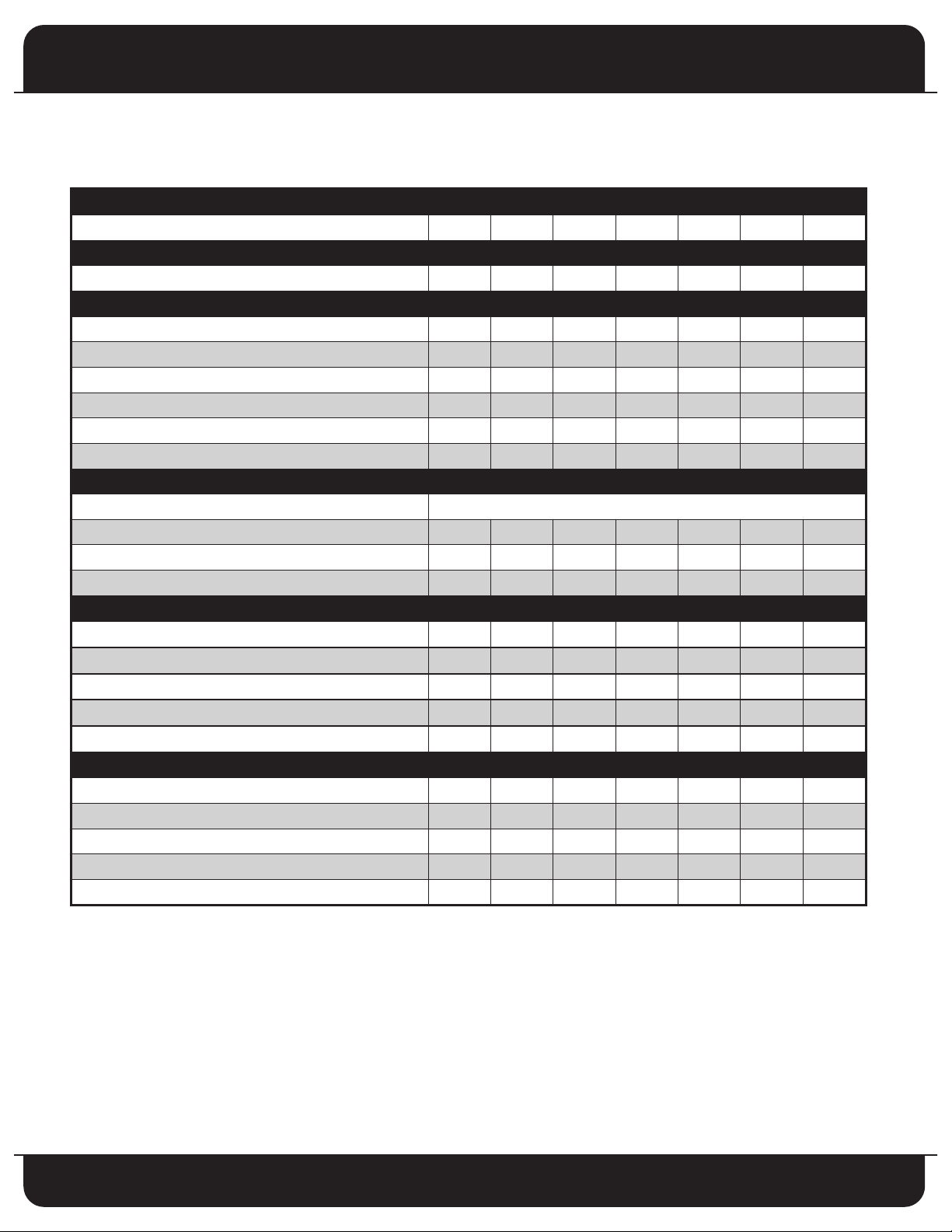
Product Specifications
PHYSICAL DATA
MODEL SIZE
PERFORMANCE DATA
NOMINAL CAPACITY (BTUH) 18,000 24,000 30,000 36,000 42,000 48,000 60,000
FAN DATA
FAN MOTOR TYPE PSC PSC PSC PSC PSC PSC PSC
HP 1/5 1/3 1/3 1/3 1/3 1/3 1/3
DIAMETER 18" 22" 22" 22" 22" 22" 24"
BLADE 3 3 3 3 3 3 3
RPM 1,050 1,050 1,050 1,050 1,050 1,050 950
CFM 1,800 3,400 3,400 3,400 3,400 3,400 4,000
OUTDOOR COIL
TYPE Enhanced Aluminum Plate Fin / Rifled Copper Tube
COIL FACE AREA (ft2) 12.2 18.2 18.2 18.2 18.2 18.2 22.2
O.D. 3/8" 7mm 7mm 7mm 7mm 7mm 7mm
FPI / ROWS 18 -1 18-2 18 -2 18 -2 18-3 18-3 18-3
ELECTRICAL DATA (208/230 – 1-60, VOLTAGE RANGE 197V - 253V)
MINIMUM CIRCUIT AMPACITY - MCA (amps)
MAXIMUM OVERCURRENT PROTECTIVE DEVICE - MOCP(amps)
COMPRESSOR RLA (Rated Load Amps) 10.0 11.4 13.6 15 18.4 20.9 29.4
COMPRESSOR LRA (Locked Rotor Amps) 41 56 67 73 95 109 134
FAN MOTOR FLA (Full Load Amps) 1.4 1.8 1.8 1.8 1.8 1.8 1.9
REFRIGERANT CONNECTIONS
LIQUID LINE CONNECTION SIZE (In. OD) 3/8 3/8 3/8 3/8 3/8 3/8 3/8
SUCTION LINE CONNECTION SIZE
RECOMMENDED LINE SET LIQUID TUBE DIAMETER (In. OD) 3/8 3/8 3/8 3/8 3/8 3/8 3/8
RECOMMENDED LINE SET SUCTION DIAMETER (In. OD) 3/4 3/4 7/8 7/8 7/8 1 1/8 1 1/8
FACTORY CHARGE - OZ. 103 164 154 164 207 233 233*
(In. OD)
2
18 24 30 36 42 48 60
13.5 16.0 18.8 20.5 24.8 27.3 38.5
3
20 25 30 35 40 45 50
3/4 3/4 7/8 7/8 7/8 7/8 7/8
NOTE: Control circuit is 24V on all units and requires external power source. Copper wire must be used from
service disconnect to unit. ALL motors/compressors contain internal overload protection.
1. Wire size should be determined in accordance with National Electrical Codes. Extensive wire runs will
require larger wire sizes.
2. Time delay fuses may be used in place of HACR circuit breaker.
* Unit uses R-410A refrigerant.
2
Specifications subject to change without notice.
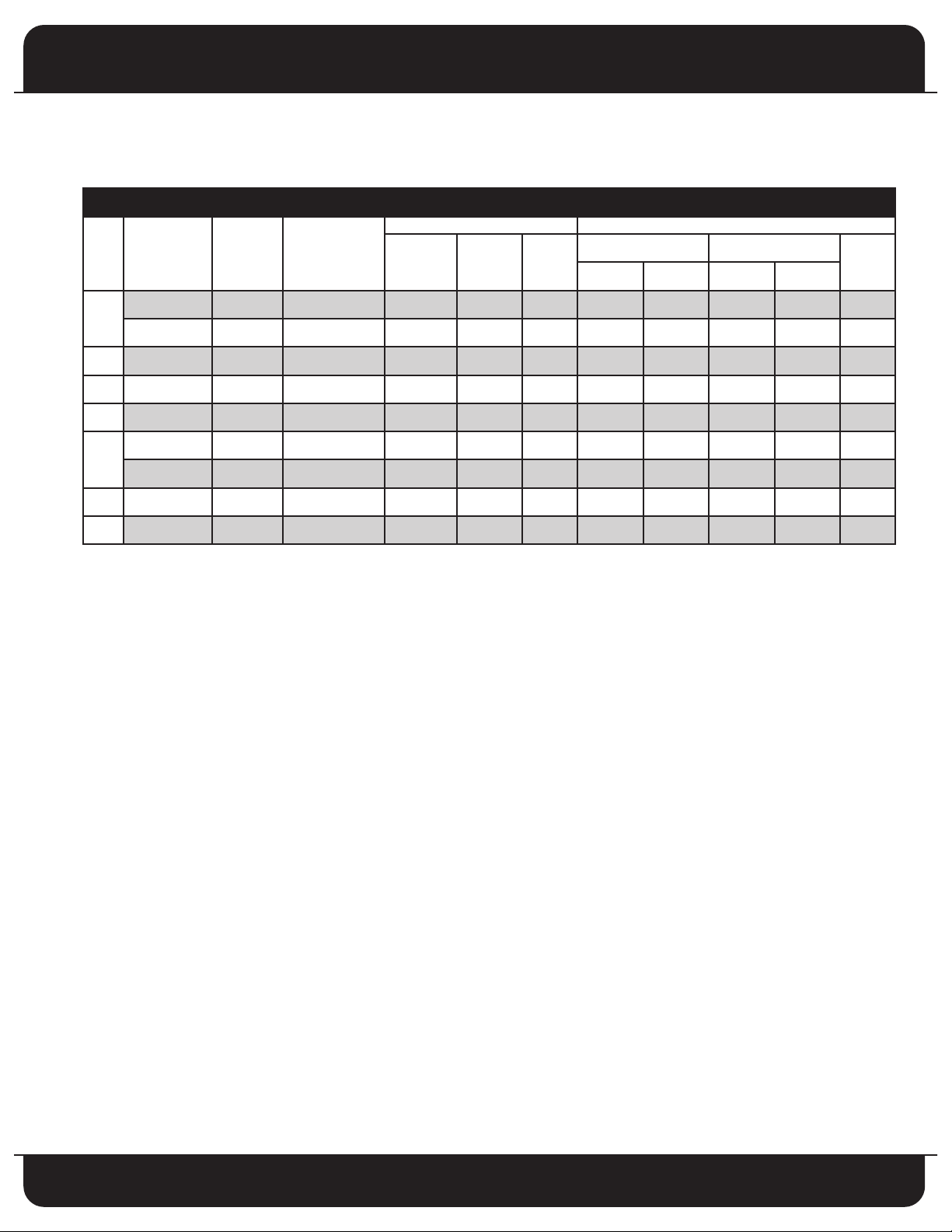
Product Specifications
ARI CERTIFIED COMBINATION RATINGS
COOLING HEATING
UNIT
SIZE
OUTDOOR
MODEL
CH18ABD1VF AFPB24A1 TXV, TDR 18,000 13.0 11.0 17,300 3.42 11,100 2.36 8.2
18
CH18ABD1VF AFPB24B1 TXV, TDR 18,000 13.0 11.0 17,300 3.42 11,100 2.36 8.2
24 CH24ACD1VF AFPB24B1 TXV, TDR 24,000 13.0 11.4 24,000 3.42 15,000 2.20 8.2
30 CH30ACD1VF AFPB36A1 TXV, TDR 28,000 13.0 11.5 28,000 3.50 18,200 2.30 8.2
36 CH36ACD1VF AFPB36A1 TXV, TDR 34,000 13.0 11.5 34,000 3.50 22,000 2.50 8.2
CH42ACD1VF AFPC48A1 TXV, TDR 40,000 13.0 11.5 40,000 3.42 23,000 2.30 8.2
42
CH42ACD1VF AFPC48B1 TXV, TDR 40,000 13.0 11.5 40,000 3.42 23,000 2.30 8.2
48 CH48ACD1VF AFPC48B1 TXV, TDR 46,000 13.0 11.5 44,000 3.42 28,400 2.50 7.8
INDOOR
MODEL
FACTORY
SUPPLIED
ENHANCEMENT
TOTAL
CAPACITY
SEER EER
HIGH TEMP LOW TEMP
CAPACITY COP CAPACITY COP
HSPF
60 CH60ACZ1VF AZFPC60B1 TXV, TDR 56,000 13.0 11.2 56,000 3.42 38,000 2.30 8.2
SEER
– Seasonal Energy Efficiency Ratio
COP – Coefficient of Performance
TDR – Time – Delay Relay
HSPF – Heating Seasonal Performance Factor
EER – Energy Efficiency Ratio
NOTES:
1. Tested combination per ARI 210/240 standard. Fedders air handlers contain the TDR as standard equipment.
2. Supplemental electric heat is not included.
3. Ratings are based on:
Cooling Standard: 80ºF db 67ºF wb indoor entering air temperature and 95ºF db air entering outdoor unit.
High – Temp Heating Standard: 70ºF db indoor entering air temperature and 47ºF db 43ºF wb air entering outdoor unit.
Low – Temp Heating Standard: 70ºF db indoor entering air temperature and 17ºF db 15ºF wb air entering outdoor unit.
3
Specifications subject to change without notice.
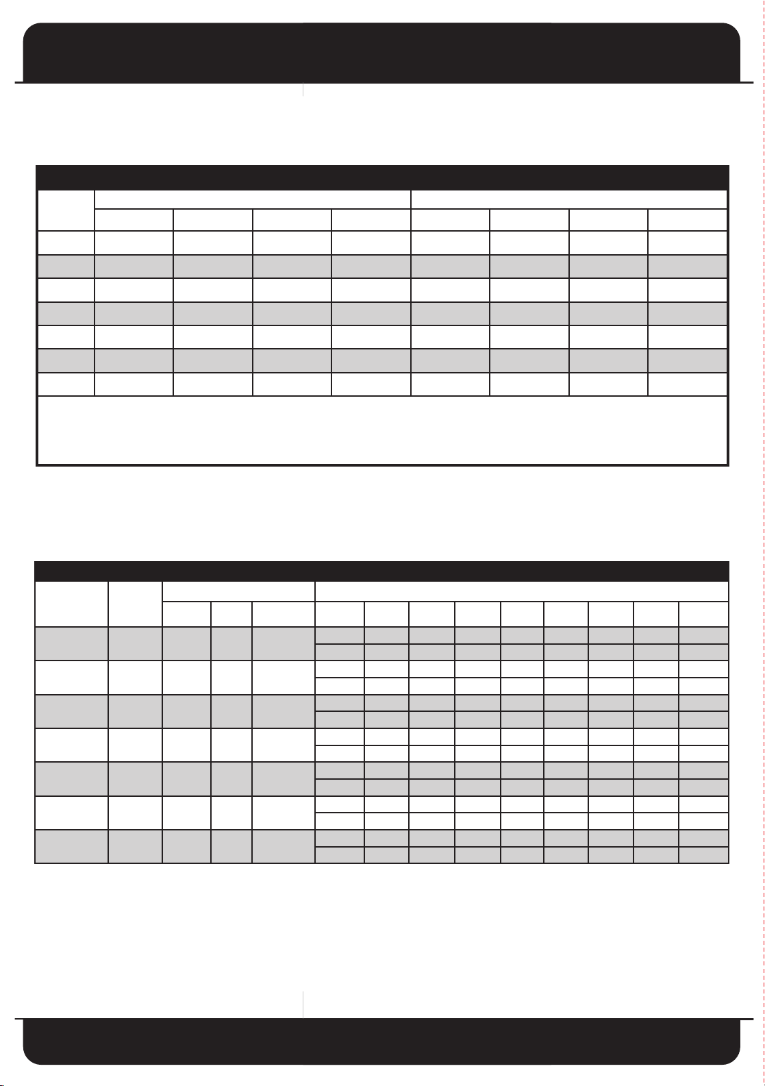
Split System Heat Pump
LINE SET LENGTH AND SIZE
BTUH
15 ft. 25 ft. 50 ft. 75 ft. 15 ft. 25 ft. 50 ft. 75 ft.
18 3/4 3/4 3/4 3/4 3/8 3/8 3/8 3/8
24 3/4 3/4 3/4 3/4 3/8 3/8 3/8 3/8
30 3/4 7/8 7/8 7/8 3/8 3/8 3/8 3/8
36 3/4 7/8 7/8 7/8 3/8 3/8 3/8 3/8
42 7/8 7/8 7/8 7/8 3/8 3/8 3/8 1/2
48 1 1/8 1 1/8 1 1/8 1 1/8 3/8 3/8 3/8 1/2
60 1 1/8 1 1/8 1 1/8 1 1/8 3/8 3/8 3/8 1/2
ecommended liquid & suction tube line size is for standard installations. The unit charge is correct for the outdoor unit, matched indoor coil and
R
5 feet of refrigerant tubing. For tubing length other than 15 feet, add or subtract the amount of refrigerant, using the difference in length multiplied
1
by the per foot value. These recommendations do not apply to Long Line Length Installations that exceed 75 feet or where there is more than 40 feet
ertical separation between indoor and outdoor units. (Lengths in excess of 75 feet or more than 40 feet vertical separation are not recommended.)
v
ote: See unit installation instructions for proper installation.
N
SUCTION LINE SIZES LIQUID LINE SIZES
OUTDOOR
UNIT
MODEL
CH18ABD1VF AFPB24A1 18,000 13 650
CH24ACD1VF AFPB24B1 24,000 13 840
CH30ACD1VF AFPB36A1 28,000 13 1,000
CH36ACD1VF AFPB36A1 34,000 13 1,200
CH42ACD1VF AFPC48A1 40,000 13 1,350
CH48ACD1VF AFPC48B1 46,000 13 1,550
CH60ACZ1VF AZFPC60B1 56,000 13 1,750
*TDR required to obtain SEER rating.
AIR
HANDLER
RATINGS AT STANDARD CONDITIONS COOLING DATA AT EXTENDED OUTDOOR AMBIENTS F.M.B.T.U.H.
BTUH
SEER*
COOLING PERFORMANCE DATA
CFM
TOT
SENSIBLE 15,250 14,950 14,600 14,200 14,050 13,800 13,500 13,250
TOTAL 25,800 25,150 24,600 24,000 23,450 22,900 22,350 21,950
SENSIBLE 19,900 19,500 19,050 18,700 18,450 18,000 17,650 17,300
TOTAL 30,050 29,450 28,750 28,000 27,200 26,550 25,800 25,250
SENSIBLE 23,100 22,600 22,050 21,700 21,450 21,050 20,800 20,550
TOTAL 36,350 35,500 34,800 34,000 33,250 32,550 31,700 30,950
SENSIBLE 28,300 27,850 27,650 27,250 26,950 26,750 26,350 26,050
TOTAL 42,700 42,550 40,950 40,000 39,000 38,000 37,400 36,800
SENSIBLE 33,250 32,900 32,100 31,500 30,550 29,600 28,450 27,600
TOTAL 49,300 48,150 46,950 46,000 44,850 43,650 42,500 41,400
SENSIBLE 40,950 39,750 38,100 36,000 34,800 33,550 32,350 31,150
TOTAL 60,550 59,000 57,450 56,000 54,300 52,450 51,100 49,850
SENSIBLE 44,550 43,950 43,100 42,350 41,700 40,950 40,500 39,600
80 85 90 95 100 105 110 115
AL
19,450 18,900 18,450 18,000 17,650 17,200 16,750 16,400
4
Specifications subject to change without notice.
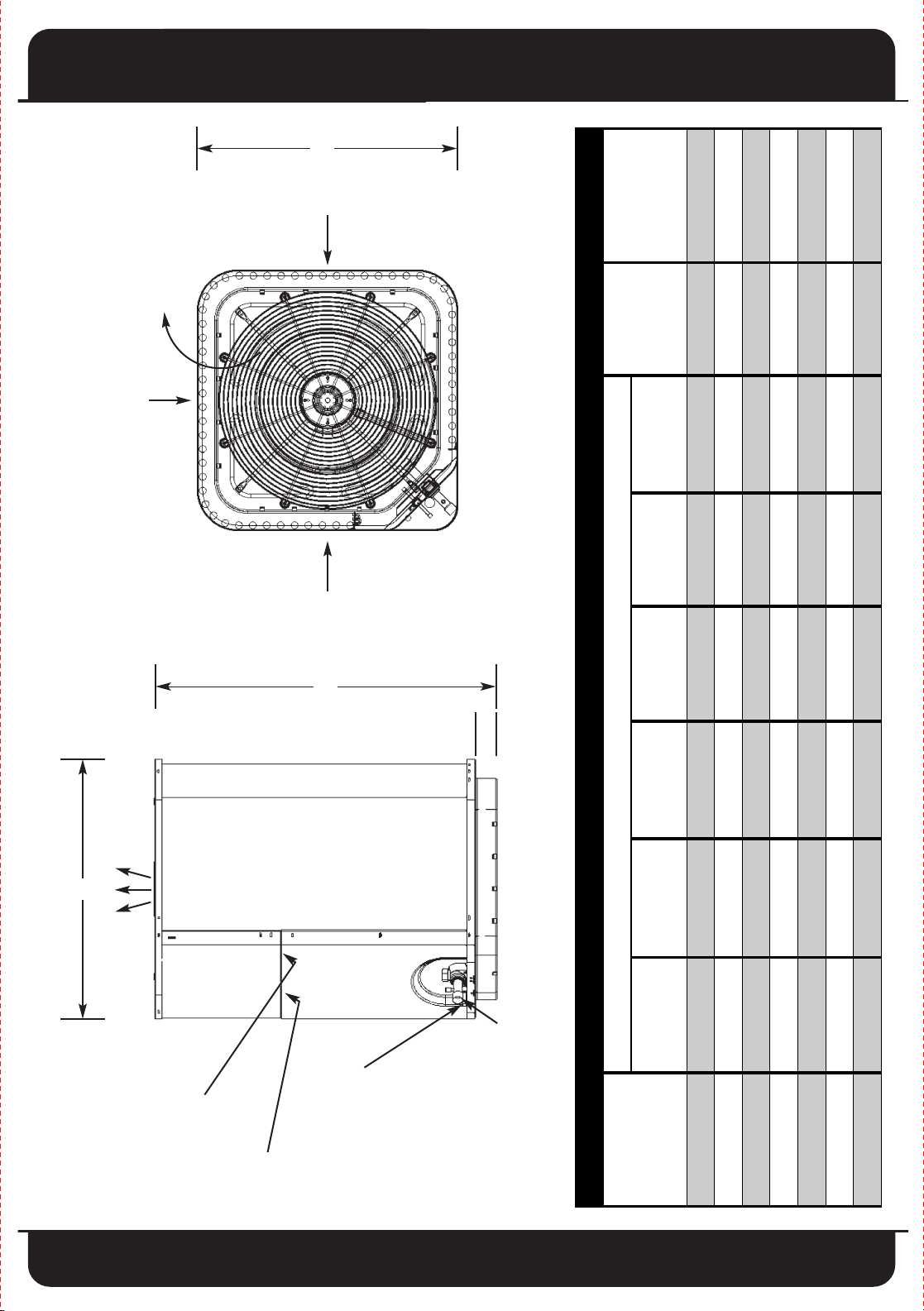
Split System Heat Pump
DIMENSIONS IN INCHES
MODELS
ALL DIMENSIONS
MINIMUM
MOUNTING
PAD SIZE
SHIPPING
DIMENSIONS
H x W x D
A B C D E F
CH18ABD1VF 21 1/2 32 1/2 21 1/2 3/8 3/4 2 1/2 24 x 24 33 x 23 x 23
CH24ACD1VF 29 1/2 32 1/2 29 1/2 3/8 3/4 2 1/2 32 x 32 33 x 31 x 31
CH30ACD1VF 29 1/2 32 1/2 29 1/2 3/8 7/8 2 1/2 32 x 32 33 x 31 x 31
CH36ACD1VF 29 1/2 32 1/2 29 1/2 3/8 7/8 2 1/2 32 x 32 33 x 31 x 31
CH42ACD1VF 29 1/2 32 1/2 29 1/2 3/8 7/8 2 1/2 32 x 32 33 x 31 x 31
CH48ACD1VF 29 1/2 32 1/2 29 1/2 3/8 7/8 2 1/2 32 x 32 33 x 31 x 31
CH60ACZ1VF 29 1/2 39 29 1/2 3/8 1 1/8 2 1/2 32 x 32 39 1/2 x 31 x 31
C
AIR IN
(FRONT)
AIR DISCHARGE
AIR IN
AIR IN
B
F
A
AIR DISCHARGE
D
LIQUID LINE
DIMENSIONS
1 1/8" HOLE
Y CONNECTION
FIELD POWER
SUPPL
1/4" HOLE
FIELD CONTROL
SUPPLY CONNECTION
CONNECTION
5
Specifications subject to change without notice.
E
VAPOR LINE
CONNECTION
Split System Heat Pump
Residential & Light Commercial
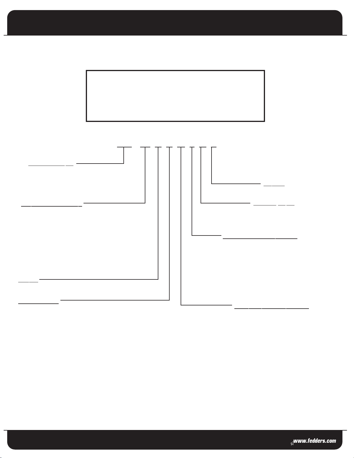
13 SEER Split System
Model Number Identification
CH 24 A B D 1 V F * A
Product Type
C = Air Conditioner
CH = Heat Pump
Brand
Nominal C
apacity
18 = 18,000 BTUH [5.28 kW]
24 = 24,000 BTUH [7.03 kW]
30 = 30,000 BTUH [8.79 kW]
36 = 36,000 BTUH [10.55 kW]
42 = 42,000 BTUH [12.31 kW]
48 = 48,000 BTUH [14.07 kW]
60 = 60,000 BTUH [17.58 kW]
Series
Chassis Size
B = 211⁄2" W x 211⁄2" D x H - Determined by BTU Size
C = 291⁄2" W x 291⁄2" D x H - Determined by BTU Size
Fitting Type
V = Sweat
Electrical Designation
1 = 208 / 230 Volts, 1 Phase, 60 Hz
2 = 220 Volts, 1 Phase, 50 Hz
3 = 208 / 230 Volts, 3 Phase, 60 Hz
4 = 460 Volts, 3 Phase, 60 Hz
5 = 230 Volts, 3 Phase, 50 Hz
6 = 380 Volts, 3 Phase, 50 Hz
Refrigerant Variations
D = R-22 Refrigerant
Z = R-410A Refrigerant
Fedders Corporation
505 Martinsville Rd.
Liberty Corner, NJ 07938 USA
(908) 604-8686
Form No. F-CH13
All product specifications reflect available information at the printing of this brochure.
Fedders reserves the right to revise or modify products and/or specifications without notice.
Copyright ©2007 Fedders North America, Inc. Fedders is a registered trademark of Fedders North America, Inc.
FD-017-0507-m
6
Specifications subject to change without notice.
 Loading...