

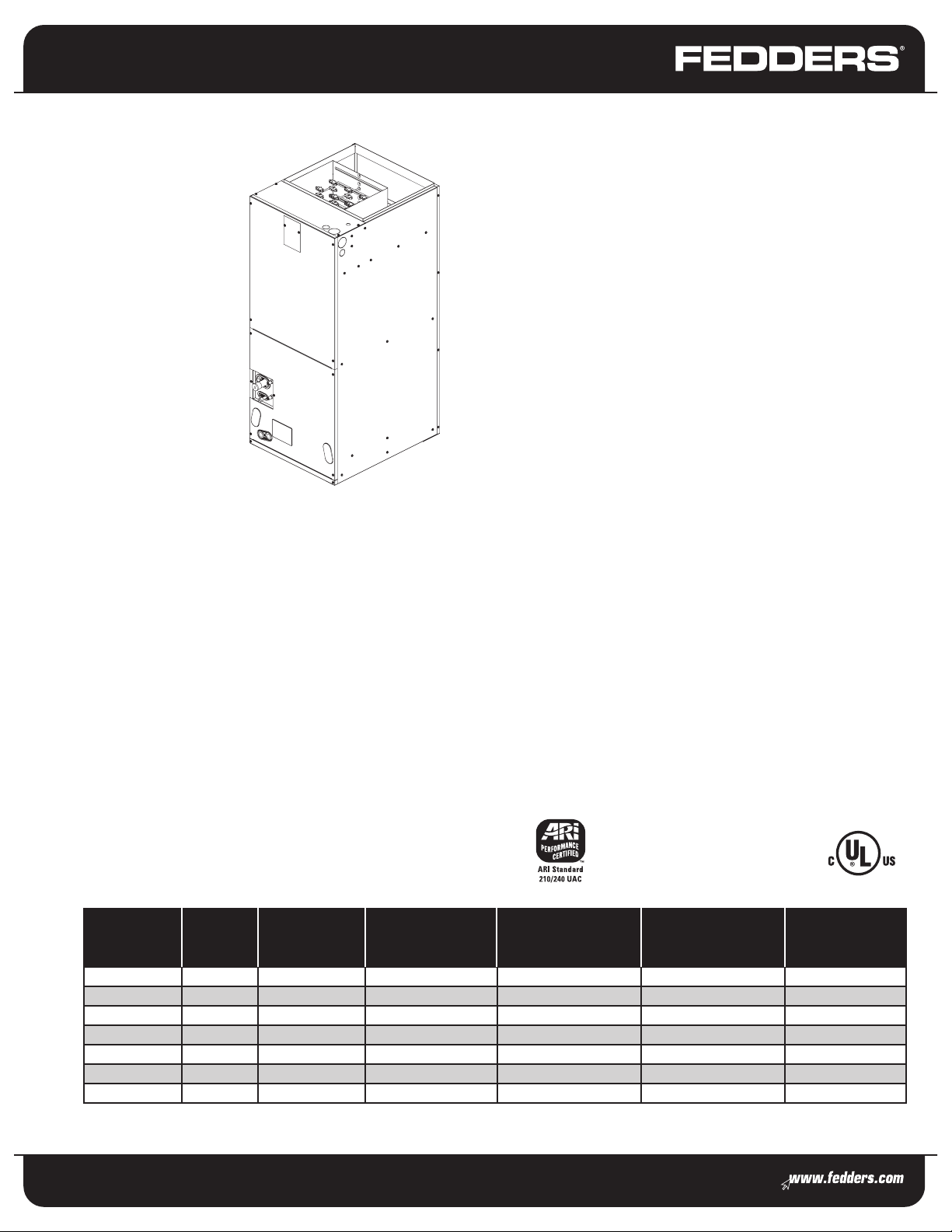
Residential & Light Commercial HVAC
Ultra Quiet Series
Electric Air Handler
11⁄2 thru 5 Tons
208/230 Volt, 1-Phase, 60 Hz
The Fedders multi-position air handlers, when
matched with our air conditioners or heat pumps,
offer a complete line of quiet, efficient split
systems for today’s heating and cooling equipment.
Easy To Install And Service
Performance
Dual rated 208/230 volt operation
1
⁄2 to 5 tons
1
External sweat refrigerant connections
TXV – factory installed standard, which precisely controls
refrigerant distribution for improved comfort and cost savings
Standard Features
Multiposition installation, upflow or horizontal left standard,
horizontal right and downflow with minor modifications
3-speed, permanently-lubricated PSC direct drive blower
motor is resilient mounted for ultra quiet, vibration-free
eration and flexible installation
op
Foil faced insulation reduces noise and bacterial growth and
features an easy to clean surface area
All indoor coils have copper tubing and aluminum fins
y relay comes standard and allows for retro-fit installations
la
e
ime D
T
imary and secondary drains on all models
r
3/4" p
MODEL TONS REFRIGERANT
AFPB24A1 1.5 - 2 R-22
AFPB24B1 1.5 - 2 R-22
AFPB36A1 2.5 - 3 R-22
AFPC48A1 3.5 - 4 R-22
AFPC48B1 4 R-22
AFPC60A1 5 R-22
AZFPC60B1 5 R-410A
AIR FLOW
RANGE
(CFM)
625 – 900 43 3/8 x 18 x 22 16 x 20 x 1 115 / 109
615 – 880 43 3/8 x 18 x 22 16 x 20 x 1 120 / 113
950 – 1,260 43 3/8 x 18 x 22 16 x 20 x 1 120 / 113
1,190 – 1,590 48 3/8 x 22 x 26 20 x 25 x 1 161 / 152
1,195 – 1,590 48 3/8 x 22 x 26 20 x 25 x 1 167 / 160
1,340 – 1,895 48 3/8 x 22 x 26 20 x 25 x 1 167 / 160
1,340 – 1,895 48 3/8 x 22 x 26 20 x 25 x 1 167 / 160
Breaker accessible from front of unit when heater applied
External Access to heater circuit breakers pull /disconnects
Provisions for field installed electrical connections from
either side of air handler cabinet
Built in filter rack
Pressure taps on suction and liquid line
Corrosion resistant condensate drain pan. Primary and
secondary drain
Optional Features
Field installed heater packages from 5 kW – 20 kW
Warranty
5-year limited parts warranty
Rated in Accordance with ARI Standard 210/240.
Certification Applies Only When Used with
Proper Components as Listed with ARI.
Additional rating information
can be found at www.aridirectory.org
DIMENSIONS
H x W x D (in)
RECOMMENDED
FILTER SIZE
H x W x D (in)
SHIP/
OPERATIONS
WEIGHT (lbs)
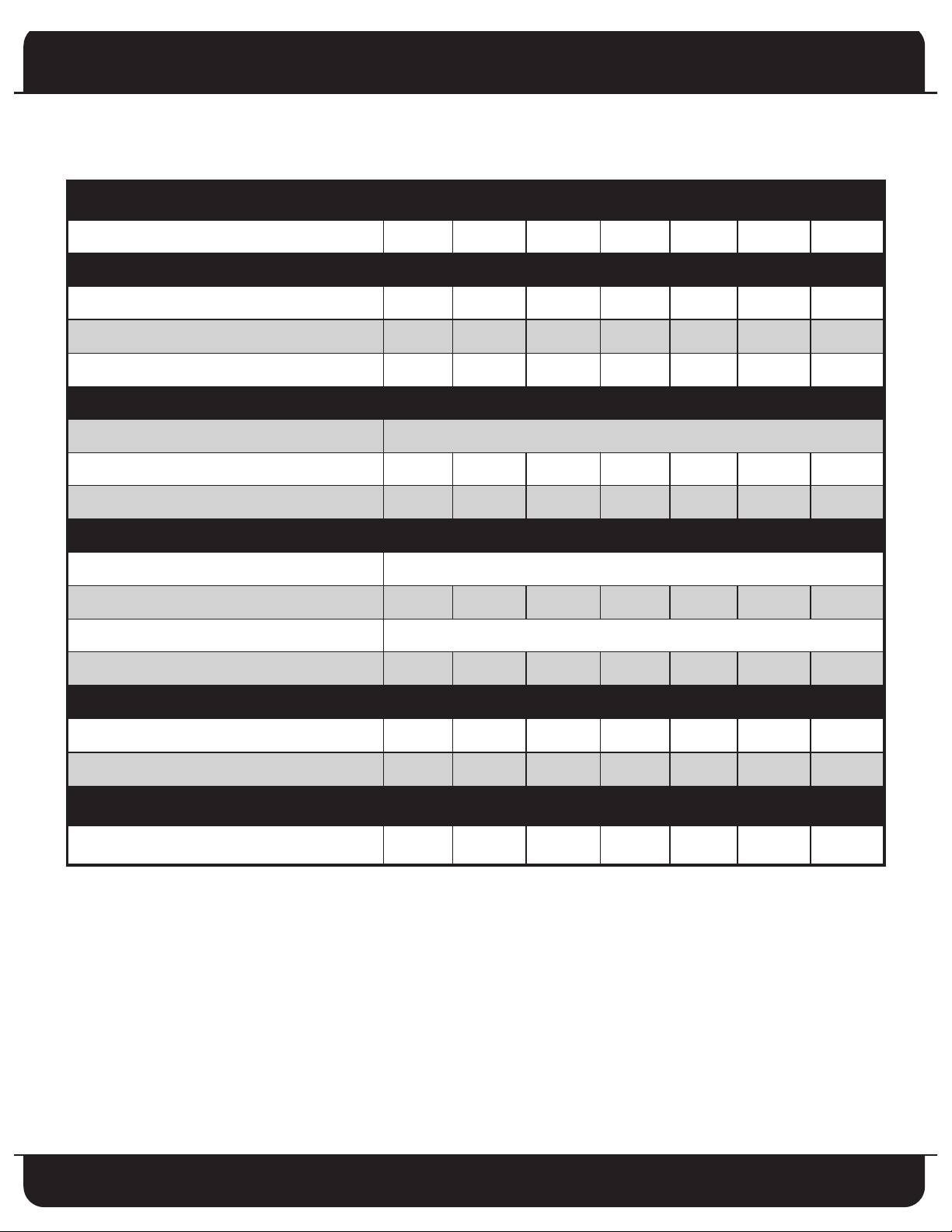
Product Specifications
HYSICAL DATA
P
MODEL NUMBER AFPB24A1 AFPB24B1 AFPB36A1 AFPC48A1 AFPC48B1 AFPC60A1 AZFPC60B1
ELECTRIC DATA (208/230 VOLT, SINGLE PHASE, 60 Hz)
V
OLTAGE
MINIMUM CIRCUIT AMPACITY MCA (AMPS)
MAXIMUM OVERCURRENT PROTECTIVE DEVICE - MOCP (AMPS)
B
LOWER
FAN MOTOR TYPE PSC
H
P
BLOWER DIMENSIONS 9 x 7 9 x 7 9 x 10 9 x 8 9 x 8 10 x 9 10 x 9
COIL DATA
TYPE A-COIL
COIL FACE AREA (ft2)
O.D.
ROWS / FPI 2 - 14 3 - 14 3 - 14 3 - 12 4 - 12 3 - 12 4 - 12
REFRIGERANT LINE CONNECTION
LIQUID LINE CONNECTION SIZE (IN. OD) 3/8 3/8 3/8 3/8 3/8 3/8 3/8
208 / 230 208 / 230 208 / 230 208 / 230 208 / 230 208 / 230 208 / 230
15 15 15 15 15 15 15
15 15 15 15 15 15 15
1
/6
4 4 4 5.8 5.8 5.8 5.8
1
/6
1
/3
1
3/8"
/2
1
/2
3
/4
3
/4
SUCTION LINE CONNECTION SIZE (IN. OD) 3/4 7/8 7/8 7/8 7/8 7/8 7/8
FIL
TER DATA
RECOMMENDED FILTER SIZE (H X W X D) (in)
(FILTER NOT SUPPLIED)
16 x 20 x 1 16 x 20 x 1 16 x 20 x 1 20 x 25 x 1 20 x 25 x 1 20 x 25 x 1 20 x 25 x 1
Clearance to Combustible Material
Clearances from the air handler to the combustibles are zero inches from all sides, top, and bottom; one inch from discharge
air plenum; and the duct within 36 inches of the plenum.
2
Specifications subject to change without notice.

Product Specifications
AIRFLOW PERFORMANCE
MODEL
NUMBER
AFPB24A1
AFPB24B1
AFPB36A1
AFPC48A1
AFPC48B1
AFPC60A1
AZFPC60B1
BLOWER
(INCHES WATER COLUMN)
SPEED
0.20 0.30 0.40 0.50 0.60
HIGH 925 900 850 795 690
MEDIUM 800 760 745 670 N/A
LOW 655 625 600 N/A N/A
HIGH 905 880 830 780 680
MEDIUM 785 735 730 655 N/A
LOW 645 615 590 N/A N/A
HIGH 1440 1350 1260 1180 1040
MEDIUM 1300 1220 1050 940 860
LOW 1160 1070 950 880 780
HIGH 1680 1640 1590 1520 1430
MEDIUM 1440 1410 1380 1340 1250
LOW 1240 1220 1190 1150 1100
HIGH 2230 2105 1990 1895 1725
MEDIUM 1950 1930 1840 1770 1590
LOW 1360 1360 1350 1340 1080
MEASURED STATIC PRESSURE INLET TO OUTLET
Specifications applicable to upflow and horizontal applications.
Air flow shown at the following conditions:
- No heat elements in Air Handler. Decrease CFM 2% for 5 kW, 7.5 kW or 10 kW heat kits. Decrease CFM 1% for 15 kW or 20 kW heat kits.
- 60 Hertz – 230 volts. Decrease CFM 6% for 208 volt operations.
- Dry coil airflow shown.
3
Specifications subject to change without notice.

Accessories
ELECTRIC HEATER KITS
PART NUMBER DESCRIPTION USE WITH MODEL SIZE
EEC05N1 5 KW, SINGLE PHASE, WITHOUT CIRCUIT BREAKER ALL
EEC05B1 5 KW, SINGLE PHASE, WITH CIRCUIT BREAKER ALL
EEC07N1 7.5 KW, SINGLE PHASE, WITHOUT CIRCUIT BREAKER ALL
EEC07B1 7.5 KW, SINGLE PHASE, WITH CIRCUIT BREAKER ALL
EEC10N1 10 KW, SINGLE PHASE, WITHOUT CIRCUIT BREAKER ALL
EEC10B1 10 KW, SINGLE PHASE, WITH CIRCUIT BREAKER ALL
EEC15B1 15 KW, SINGLE PHASE, WITH CIRCUIT BREAKER
EEC20B1 20 KW, SINGLE PHASE, WITH CIRCUIT BREAKER
AFPB36A1, AFPC48A1, AFPC48B1,
AFPB60A1, AZFPB60B1
AFPB36A1, AFPC48A1, AFPC48B1,
AFPB60A1, AZFPB60B1
ELECTRIC HEAT - ELECTRICAL DATA
kW
240
VAC
Phase
No. of
Supply
Circuits
MBTUH
208/240
Heat
Load
Amps
Min.
Wire À
Ampacity
SINGLE CIRCUIT SUPPLY DUAL CIRCUIT SUPPLY
Max.
Fuse Á
Wire Size  Ground Size Á Min. Wire Ampacity À Max. Fuse Size Á Wire Size  Ground Size Â
AWG MM2 AWG MM2 Ckt 1 Ckt 2 Ckt 1 Ckt 2
Size
A
Ckt 1
WG
/
MM2
A
Ckt 2
WG
/
MM2
A
Ckt 1
WG
/
MM2
A
Ckt 2
WG
0 1 1 - - 5.0 15 14 2.1 14 2.1 - - - - - - - -
5* 1 1 14.8 / 17.1 20.9 30 30 10 5.3 10 5.3 - - - - - - - -
7.5* 1 1 22.1 / 25.6 31.3 43 50 8 8.4 10 5.3 - - - - - - - -
10* 1 1 29.5 / 34.1 41.7 57 60 6 13.3 10 5.3 - - - - - - - -
15* 1 1 or 2 44.3 / 51.2 62.5 83 90 4 21.2 8 8.4 57 26 60 30 6 / 13.3 10 / 5.3 10 / 5.3 10 / 5.3
20* 1 1 or 2 59.0 / 68.2 83.4 109 110 2 33.6 6 13.3 57 53 60 60 6 / 13.3 10 / 13.3 10 / 5.3 10 / 5.3
NOTES:
*kW does not include motor watts.
À Ampacities and over current protection based on largest air handler motor load. Refer to specific name plate for exact ampacity
and overcurrent protection size.
Minimum wire ampacity values are used for sizing field power conductors. Refer to the National Electrical Code (latest version), Article 310,
for sizing conductors.
NOTE: when more than three current-carrying conductors are in the same conduit, the conductor's ampacity must be derated.
Á Maximum size fuse or HACR-type circuit breaker for field wiring protection.
 Wire size based on 75°C copper wire with no more than three current-carrying conductors in the same conduit.
All wiring must conform to the National Electrical Code and all local codes.
/
MM2
4
Specifications subject to change without notice.

Product Specifications
LINE
VOLTAGE
KNOCKOUTS
LOW VOLT
E
B
D
C
CONNECTIONS
TO TXV
ACCESS COVER
G
INLET DEPTH
F
INLET WIDTH
I
H
A
DIMENSIONS
5
Specifications subject to change without notice.

Electric Air Handler
Residential & Light Commercial Air Handler
Model Number Identification
A F P B 24 A 1 * A
Product Type
A = Air Handler
Brand
R-22 Models
Motor
P = PSC
Chassis Size
B = 43 3/8"H x 18"W x 22"D
C = 48 3/8"H x 22"W x 26"D
Nominal BTUH
24 = 18,000/24,000 BTU/H (5.28 kW) / (7.03 kW)
36 = 30,000/36,000 BTU/H (8.79 kW) / (10.55 kW)
42 = 42,000 BTU/H (12.31 kW)
48 = 48,000 BTU/H (14.07 kW)
60 = 60,000 BTU/H (17.58 kW)
A Z F
Product Type
A = Air Handler
410A Refrigerant
Brand
Motor
P = PSC
Chassis Size
B = 43 3/8"H x 18"W x 22"D
C = 48 3/8"H x 22"W x 26"D
R-410A Models
P C 60
B 1 * A
Electrical Designation
1 = 208 / 230 Volts, 1 Phase, 60 Hz
2 = 220 Volts, 1 Phase, 50 Hz
3 = 208 / 230 Volts, 3 Phase, 60 Hz
4 = 460 Volts, 3 Phase, 60 Hz
5 = 230 Volts, 3 Phase, 50 Hz
6 = 380 Volts, 3 Phase, 50 Hz
Design Series
A = A Series
Electrical Designation
1 = 208 / 230 Volts, 1 Phase, 60 Hz
Volts, 1 Phase, 50 Hz
2 = 220
3 = 208 / 230 Volts, 3 Phase, 60 Hz
4 = 460 Volts, 3 Phase, 60 Hz
5 = 230 Volts, 3 Phase, 50 Hz
olts, 3 Phase, 50 Hz
V
6 = 380
Design Series
A = A Series
Nominal BTUH
24 = 18,000/24,000 BTU/H (5.28 kW) / (7.03 kW)
36 = 30,000/36,000 BTU/H (8.79 kW) / (10.55 kW)
42 = 42,000 BTU/H (12.31 kW)
48 = 48,000 BTU/H (14.07 kW)
60 = 60,000 BTU/H (17.58 kW)
Fedders Corporation
505 Martinsville Rd.
Liberty Corner, NJ 07938 USA
(908) 604-8686
Form No. F-13AH
All product specifications reflect available information at the printing of this brochure.
Fedders reserves the right to revise or modify products and/or specifications without notice.
Copyright ©2007 Fedders North America, Inc. Fedders is a registered trademark of Fedders North America, Inc.
FD-015-0407-k
6
Specifications subject to change without notice.
 Loading...