

Page 1
For Health Hazard Applications
ES-F-LF825YA
Job Name
Job Location
Engineer
Approval
LEAD FREE
–––––––––––––––––––––––––––––––––––––––––––
–––––––––––––––––––––––––––––––––––––––––
–––––––––––––––––––––––––––––––––––––––––––––
–––––––––––––––––––––––––––––––––––––––––––––
*
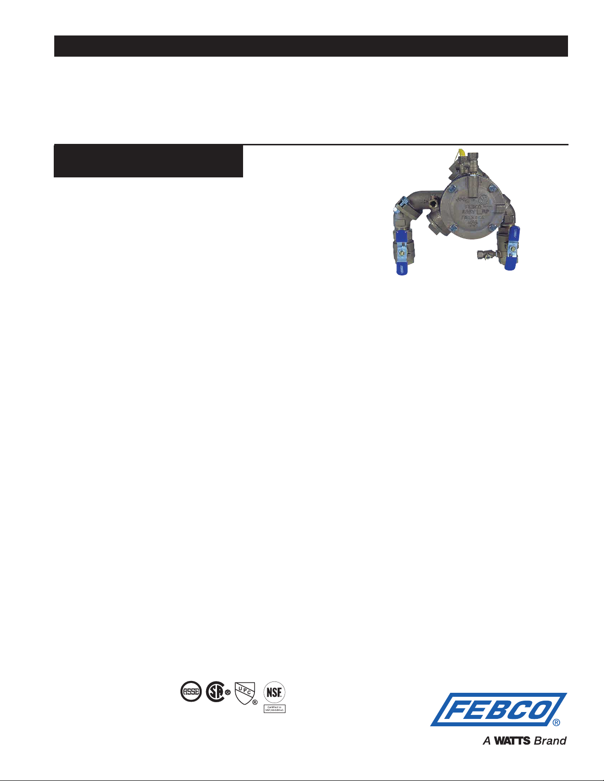
Series LF825YA
Angle Pattern Reduced
Pressure Zone Assemblies
Size: 3⁄4" - 2" (20 - 50mm)**
The FEBCO Series LF825YA Reduced Pressure Zone Assemblies
are used to protect against toxic fluids in water services to industrial
plants, hospitals, morgues, mortuaries, and chemical plants. They
are also used in irrigation systems, boiler feeds, water lines and
other installations requiring the highest level of mechanical protection. The LF825YA features Lead Free* construction to comply with
Lead Free* installation requirements. End connection – NPT ANSI/
ASME B1.20.1
Features
• Installation versatility simplifies new and retrofit installations.
• Eliminates pipe elbows, nipples and unions from the installation.
• Reduces installation time, labor costs and materials.
• Compact design simplifies retrofit.
• Integral flanged union connections allow assembly to be
removed from the line for freeze protection or maintenance without the danger of spool substitution.
• Approved by the Foundation for Cross-Connection Control and
Hydraulic Research at the University of Southern California.
• Modular relief valve and check valve internal components for
ease of maintenance.
• Smaller, less costly protective enclosures can be used to provide
freeze and vandalism protection due to compact size of valve.
• Field tested design for reliability and performance.
• Replaceable seat rings for longer valve life.
• Low head loss for optimum performance.
Operation
In a flow condition, the check valves are open with the pressure
between the checks, called the zone, being maintained at least 5psi
(34 kPa) lower than the inlet pressure. The relief valve is held closed
by the pressure differential.
Should abnormal conditions arise under no flow or reversal of flow,
the differential relief valve will open and discharge to maintain the
zone at least 2psi (14 kPa) lower than the supply.
When normal flow resumes, the zone’s differential pressure will
return and the relief valve will close.
Approvals – Standards
• Approved by the Foundation for Cross-Connection Control and
Hydraulic Research at the University of Southern California.
• AWWA C511 Conformance
Contractor
Approval
Contractor’s P.O. No.
Representative
––––––––––––––––––––––––––––––––––––––––––––
–––––––––––––––––––––––––––––––––––––––––––––
–––––––––––––––––––––––––––––––––––
––––––––––––––––––––––––––––––––––––––––
LF825YA
U.S. Patent No. 4,991,622
Specifications
The reduced pressure zone assemblies shall consist of two independently operating, spring loaded, "Y" pattern check valves and
one hydraulically dependent differential relief valve. Should the differential between the upstream and the zone of the unit drop to
2psi (14 kPa), the differential relief valve shall open and maintain the
proper differential.
Mainline valve body and caps including relief valve body and cover
shall be Lead Free* cast copper silicon alloy. Check valve moving
members shall be center stem guided. Relief valve shall have a
removable seat ring. Check valve and relief valve components shall
be constructed so they may be serviced without removing the valve
body from the line. All seat discs shall be reversible.
The assembly shall include flanged unions located between the
mainline valve body and the ball valve shutoffs to allow for field
removal for freeze protection or maintenance without danger
of spool replacement. The Lead Free* Angle Pattern Reduced
Pressure Zone Assemblies shall comply with state codes and standards, where applicable, requiring reduced lead content.
The assembly shall be rated to 175psi (12.1 bar) water working
pressure and water temperature range from 32ºF to 140ºF (0ºC
– 60ºC). The assembly shall meet the requirements of the USC
Foundation of Cross-connection Control and Hydraulic Research,
Eighth Edition.
The assembly shall be a FEBCO Series LF825YA or prior approved equal.
Materials
Main valve body: Lead Free* Cast Copper Silicon Alloy
Relief valve body: Lead Free* Cast Copper Silicon Alloy
Elastomers: Nitrile Seat Discs
Diaphragms: Nitrile, fabric reinforced
Springs: Stainless Steel
Pressure – Temperature
Maximum working pressure: 175psi (12.1 bar)
Hydrostatic test pressure: 350psi (24.1 bar)
Temperature range: 32ºF to 140ºF (0ºC to 60ºC)
* The wetted surface of this product contacted by consumable
water contains less than 0.25% of lead by weight.
** Metric Dimensions are nominal pipe diameter. This product is
produced with NPT threaded end connections.
1013 B64.4
FEBCO product specifications in U.S. customary units and metric are approximate and are provided for reference only. For precise measurements,
please contact FEBCO Technical Service. FEBCO reserves the right to change or modify product design, construction, specifications, or materials without prior notice and without incurring any obligation to make such changes and modifications on FEBCO products previously or subsequently sold.
Page 2
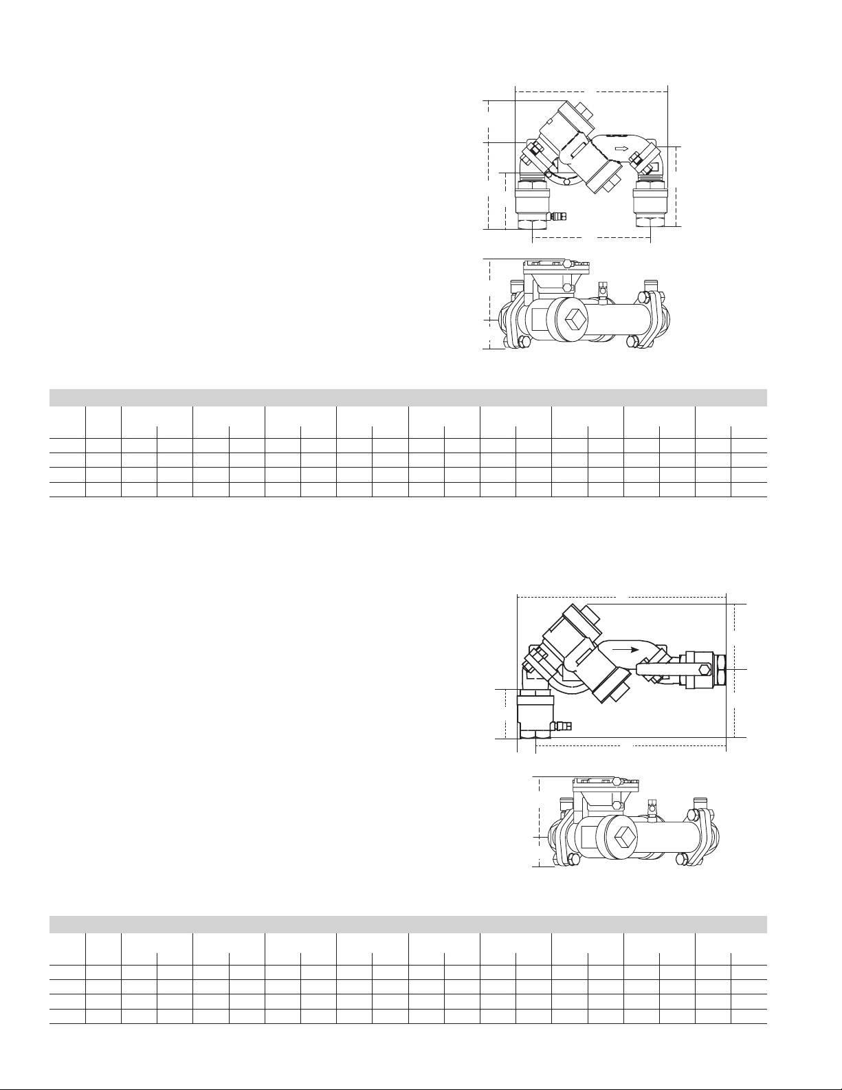
Series LF825YA / Vertical Up Flow In - Vertical Down Flow Out
Legend:
A
A Overall lay length, outside dimension
B Centerline of inlet shutoff to centerline of outlet shutoff
C
C Centerline of assemble to top
D End of inlet shutoff to centerline of assembly
D1 Centerline of assembly to end of outlet shutoff
E Centerline of assembly to outside of relief valve
F Bottom of relief port to end of inlet shutoff
D
F
D1
G Centerline of assembly to outside of flange
B
E
G
Dimensions – Weights
Size: 3⁄4" - 2 (20 - 50mm)**
SIZE (DN) DIMENSIONS WEIGHT
A B C D D1 E F G
in. in. in. mm in. mm in. mm in. mm in. mm in. mm in. mm In. mm lbs. kgs
3
⁄4 20 10 254 81⁄2 216 31⁄4 83 47⁄8 124 45⁄8 118 41⁄8 105 31⁄2 89 15⁄8 41 15.0 6.8
1 25 10
1
⁄4 260 81⁄2 216 31⁄4 83 51⁄4 133 5 127 41⁄8 105 37⁄8 98 15⁄8 41 16.5 7.5
11⁄2 40 141⁄4 362 111⁄2 292 41⁄2 114 67⁄8 175 61⁄2 165 5 127 45⁄8 118 25⁄8 67 38.0 17.2
2 50 147⁄8 378 111⁄2 292 41⁄2 114 71⁄2 191 71⁄2 181 5 127 51⁄4 133 25⁄8 67 41.0 18.6
†
G Dimension are based on standard vertical flow in / vertical flow out configuration.
Note: All dimensions are approximate. Allowances must be made for normal manufacturing tolerances.
†
Series LF825YA / Vertical Up Flow In - Horizontal Flow Out
A
Legend:
A Overall lay length, outside dimension
B Centerline of inlet shutoff to centerline of outlet shutoff
C Centerline of assemble to top
D End of inlet shutoff to centerline of assembly
E Centerline of assembly to outside of relief valve
F Bottom of relief port to end of inlet shutoff
F
G Centerline of assembly to outside of flange
B
E
G
Dimensions – Weights
Size: 3⁄4" - 2" (20 - 50mm)**
SIZE DIMENSIONS WEIGHT
A B C D D1 E F G
in. mm in. mm in. mm in. mm in. mm in. mm in. mm in. mm in. mm lbs. kgs
3
⁄4 20 125⁄8 321 117⁄8 302 41⁄2 114 35⁄8 92 n/a n/a 41⁄8 105 31⁄2 89 15⁄8 41 15.0 6.8
1 25 13
1
⁄3 339 121⁄4 311 41⁄2 114 4 102 n/a n/a 41⁄8 105 37⁄8 98 15⁄8 41 16.5 7.5
11⁄2 40 18 457 165⁄8 422 6 152 51⁄4 133 n/a n/a 5 127 45⁄8 118 25⁄8 67 38.0 17.2
2 50 19 483 171⁄4 438 6 152 57⁄8 149 n/a n/a 5 127 51⁄4 133 25⁄8 67 41.0 18.6
†
G Dimension are based on standard vertical flow in / vertical flow out configuration.
Note: All dimensions are approximate. Allowances must be made for normal manufacturing tolerances.
†
C
D
Page 3

Series LF825YA / Horizontal Flow In - Vertical Down Flow Out
Legend:
A
A Overall lay length, outside dimension
B Centerline of inlet shutoff to centerline of outlet shutoff
C Centerline of assemble to top
D End of outer shutoff to centerline of assembly
E Centerline of assembly to outside of relief valve
F Bottom of relief port to end of inlet shutoff
F
G Centerline of assembly to outside of flange
B
E
G
Dimensions – Weights
Size: 3⁄4" - 2" (20 - 50mm)**
SIZE DIMENSIONS WEIGHT
A B C D D1 E F G
in. mm in. mm in. mm in. mm in. mm in. mm in. mm in. mm in. mm lbs. kgs
3
⁄4 20 127⁄8 327 121⁄8 308 41⁄2 114 35⁄8 92 n/a n/a 41⁄8 105 31⁄2 89 15⁄8 41 15.0 6.8
1 25 13
3
⁄8 340 121⁄2 318 41⁄2 114 4 102 n/a n/a 41⁄8 105 37⁄8 98 15⁄8 41 16.5 7.5
11⁄2 40 183⁄8 467 17 432 6 152 51⁄4 133 n/a n/a 5 127 45⁄8 118 25⁄8 67 38.0 17.2
2 50 193⁄8 492 175⁄8 448 6 152 57⁄8 149 n/a n/a 5 127 51⁄4 133 25⁄8 67 41.0 18.6
†
G Dimension are based on standard vertical flow in / vertical flow out configuration.
Note: All dimensions are approximate. Allowances must be made for normal manufacturing tolerances.
†
C
D
Series LF825YA / Horizontal
Legend:
A Overall lay length, outside dimension
C Centerline of assemble to top
A
E Centerline of assembly to outside of relief valve
G Centerline of assembly to outside of flange
E
G
C
Dimensions – Weights
Size: 3⁄4" - 2" (20 - 50mm)**
SIZE DIMENSIONS WEIGHT
A B C D D1 E F G
in. mm in. mm in. mm in. mm in. mm in. mm in. mm in. mm in. mm lbs. kgs
3
⁄4 20 151⁄2 394 n/a n/a 41⁄2 114 n/a n/a n/a n/a 41⁄8 105 n/a n/a 15⁄8 41 15.0 6.8
1 25 16
1
⁄4 413 n/a n/a 41⁄2 114 n/a n/a n/a n/a 41⁄8 105 n/a n/a 15⁄8 41 16.5 7.5
11⁄2 40 22 559 n/a n/a 6 152 n/a n/a n/a n/a 5 127 n/a n/a 25⁄8 67 38.0 17.2
2 50 233⁄8 594 n/a n/a 6 152 n/a n/a n/a n/a 5 127 n/a n/a 25⁄8 67 41.0 18.6
†
G Dimension are based on standard vertical flow in / vertical flow out configuration.
Note: All dimensions are approximate. Allowances must be made for normal manufacturing tolerances.
†
Page 4

Typical Installation
The FEBCO Series LF825YA provides versatility in installation
because it can be installed in any of four configurations. The most
typical configuration is shown in the vertical up flow in/vertical down
flow out diagram. This provides for an extremely short lay length
which is advantageous in areas of limited space for installation within a protected enclosure. Cost savings can be realized due to the
reduction in materials needed such as nipples, elbows, unions, and
size of the enclosure. With the integral flanged union connections,
the assembly can be removed from the line for freeze protection
without a spool substitution. It is not recommended that any backflow prevention assembly be removed from the line for maintenance
unless assurance can be made that a spool cross-connection cannot be substituted. The flanged union connection mounted at 45°
will provide this assurance. The FEBCO Series LF825YA is shipped
in the configuration shown in the vertical up flow/vertical down flow
out diagram, but can easily be modified to the three other configurations (shown on inside of this specification sheet) simply by
removing the bolts to rotate the end adapters.
With any configuration, material and labor savings can be achieved.
The FEBCO Series LF825YA is the only Reduced Pressure Zone
Assembly which provides these options in a compact, integral
assembly. All internal components are interchangeable with the
FEBCO Series LF825Y providing the same ease of maintenance
and reliable operation.
Reduced Pressure Zone Assemblies should be installed with a minimum clearance of 12" (300mm) between port and floor or grade.
They must be installed where discharge will not be objectionable
and can be positively drained away. They should be installed where
easily accessible for testing and maintenance and must be protected from freezing. Thermal water expansion and/or water hammer
downstream of the backflow preventer can cause excessive pressure. Excessive pressure situations should be eliminated to avoid
possible damage to the system and device.
Capacity
kPa psi
138 20
103 15
69 10
headloss
34 5
0 5 10 15 20 25 30 (gpm)
0 19 38 57 76 95 114 (lpm)
5 7.5 10 15 (fps)
1.5 2.3 3.1 4.6 (mps)
kPa psi
138 20
103 15
69 10
headloss
34 5
0 10 20 30 40 50 60 (gpm)
0 38 76 114 276 345 414 (lpm)
5 7.5 10 15 20 (fps)
1.5 2.3 3.1 4.6 6.1 (mps)
kPa psi
138 20
103 15
headloss
69 10
34 5
3
⁄4" (20mm)**
1" (25mm)**
11/2" (40mm)**
0 20 40 60 80 100 120 (gpm)
0 138 276 414 552 689 827 (lpm)
5 7.5 10 15 (fps)
1.5 2.3 3.1 4.6 (mps)
Protective
Enclosure
Wye Strainer
Optional
Water Meter
Side view of assembly in
vertical in / out flow configuration
12" Min.
(300mm)
kPa psi
138 20
103 15
headloss
69 10
34 5
0 40 80 120 160 200 240 (gpm)
0 276 552 827 1103 1379 1655 (lpm)
5 7.5 10 15 (fps)
1.5 2.3 3.1 4.6 (mps)
2" (50mm)**
** Metric Dimensions are nominal pipe diameter. This product is
produced with NPT threaded end connections.
NOTICE
The information contained herein is not intended to replace the full
product installation and safety information available or the experience of a trained product installer. You are required to thoroughly
read all installation instructions and product safety information
before beginning the installation of this product.
USA: Tel: (800) 767-1234 • Fax: (800) 788-4491 • FEBCOonline.com
Canada: Tel: (905) 332-4090 • Fax: (905) 332-7068 • FEBCOonline.ca
Latin America: (52) 81-1001-8600 • Fax: (52) 81-8000-7091 • FEBCOonline.com
ES-F-LF825YA 1622 © 2017 FEBCO
 Loading...