FEBCO 860 User Manual

IOM-F-RV
I N S T A L L A T I O N , O P E R A T I O N , M A I N T E N A N C E
Relief Valve Assembly Instructions
Series 825YD, 826YD, 860, 880V
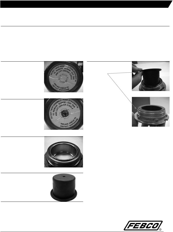
STEP #1:
When cleaning relief valve, remove module assembly from relief valve body by pulling, not twisting.
STEP #2:
If module repair is necessary, remove plastic label from around pan head retaining screw.
STEP 3:
Remove retaining screw and completely disassemble relief valve module. Thoroughly clean main guide.
STEP 4:
New inner diaphragm will come in kit with fabric side out and the beaded flange positioned up, as shown.
Repair Kits: 905102, 905316, 905192, 905187, 905188, 905189, 905190, 905191, 905227, 905228, 905229
STEP 5:
Position inner diaphragm over the main guide and drop into place with beaded flange fully engaging groove on main guide.

MAINTENANCE MANUAL SERIES 825YD, 826YD, 860, 880V
STEP 6:
Clean or replace plastic slip ring. Clean the brass diaphragm retainer. Lightly lubricate retainer threads with a food grade petroleum jelly or equal. Place slip ring into retainer. Screw retainer with slip ring onto main guide, securing inner diaphragm. Make sure the retainer is secure.
STEP 7:
Push inner diaphragm back through main guide until top of the diaphragm is flush with the top of the retainer.
STEP 8:
Turn guide/diaphragm assembly upside down and work disc holder into guide until flush with diaphragm.
STEP 9:
Push the disc holder through the guide while holding the diaphragm flush against the end of the holder. Continue until the holder stops on the guide. Place the assembly on a flat surface with the diaphragm facing up.
This will ensure that excess rubber will roll to the inside of the main guide when the holder assembly strokes, otherwise the diaphragm will crack and leak.
STEP 10:
Place flow washer on top of the diaphragm with cross channels facing upward (Series 860 and 880V ONLY). Line up the center holes, then place the spring into the guide.
2
 Loading...