

Page 1
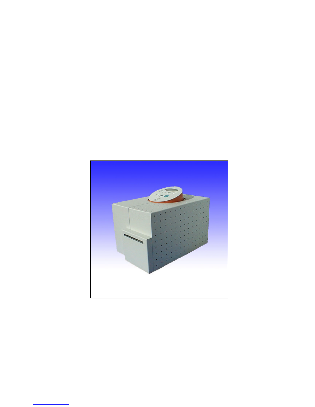
User ManualUser Manual
Label Printer
ECO 200ECO 200
Revision: January 2003
3073.02.994.90.06
Page 2

Page 3

User Manual ECO 200
Introduction
F+D Feinwerk- und Drucktechnik GmbH
Kirchenstraße 38, D-69239 Neckarsteinach
Tel.: 06229 7000, Fax: 06229 70067
E-Mail: [email protected], Internet: http://www.fuddruck.de
3
Contents
1. Introduction .......................................................................................................4
2. Initial Start Up....................................................................................................5
2.1 Preparation of Location...................................................................................................... 5
2.2 Security Advice..................................................................................................................5
2.3 Unpacking..........................................................................................................................5
2.4 Connection of Mains Cable................................................................................................5
2.5 Insertion of Paper and Transfer Ribbon..............................................................................6
2.6 Printout of a Test Label...................................................................................................... 7
2.7 Parallel Interface................................................................................................................7
2.8 Serial Interface...................................................................................................................8
2.9 Transporting the Printer .....................................................................................................8
3. Operating ..........................................................................................................9
3.1 Control Panel.....................................................................................................................9
3.1.1 LCD-Display................................................................................................................9
3.1.2 Power- and Error-Display............................................................................................ 10
3.1.3 Keys...........................................................................................................................10
3.2 Main Menu Mode...............................................................................................................11
3.3 Sub-Menu Mode................................................................................................................11
3.3.1 Menu and Parameters.................................................................................................13
3.3.2 Printer Infos................................................................................................................14
3.3.3 Macro Navigater .........................................................................................................15
3.3.4 Label Data..................................................................................................................16
3.3.5 Print Parameters.........................................................................................................18
3.3.6 Printer Specs..............................................................................................................19
3.3.7 Character / LCD ..........................................................................................................21
4. Maintenance......................................................................................................22
4.1 Ribbon- and Paper-Changing .............................................................................................22
4.2 Cleaning of the Thermal Print Head ...................................................................................22
4.3 Cleaning of the Feed Rollers..............................................................................................22
4.4 Changing of Thermal Print Head........................................................................................22
4.5 Update of printer software ECO 200...................................................................................23
5. Hardware Modifications.....................................................................................24
5.1 Thermal Direct Printing ......................................................................................................24
5.2 Transfer Device .................................................................................................................24
5.3 Carrier Foil Rewinding Device............................................................................................24
5.4 Front Rewinder..................................................................................................................24
5.5 Cutting Device ...................................................................................................................24
5.6 Dispensing Device.............................................................................................................24
5.7 External Rewinder / Winder................................................................................................25
6. Service Diagnosis..............................................................................................26
6.1 Improvement of the Printing Quality ...................................................................................26
6.2 Error Correction.................................................................................................................27
6.2.1 Error Level 1...............................................................................................................28
6.2.2 Error Level 2...............................................................................................................28
6.2.3 Error Level 3...............................................................................................................28
7. Accessories, Options.........................................................................................29
8. Technical Data..................................................................................................30
9. Declaration of Conformity..................................................................................31
10. Index .................................................................................................................32
Page 4
4 User Manual ECO 200
Introduction
F+D Feinwerk- und Drucktechnik GmbH
Kirchenstraße 38, D-69239 Neckarsteinach
Tel.: 06229 7000, Fax: 06229 70067
E-Mail: [email protected], Internet: http://www.fuddruck.de
1. Introduction
With the ECO 200 you have purchased a professional label printer.
Developed and produced by F+D Feinwerk- und Drucktechnik GmbH,
the ECO 200 sets new bench marks in the field of industrial application
of label printers.
Based on years of experience with the HFP-printer-line a new
generation of printers was created. Above all the printing speed as well
as the printing quality have been improved considerably.
In addition many more possibilities for comfort and operation are now at
the customers disposal.
The ECO 200 can be handled simply and easily by means of a LCDdisplay and 6 keys. Nevertheless, you should take the time to read this
user manual, in order to be able to use all the possibilities of this printer
to an optimum.
At the beginning you will learn how to initialise this printer. After you are
familiar with the operation of the printer, this manual will render a good
service to you for quick reference. Please keep this manual safe.
Page 5
User Manual ECO 200
Initial Start Up
F+D Feinwerk- und Drucktechnik GmbH
Kirchenstraße 38, D-69239 Neckarsteinach
Tel.: 06229 7000, Fax: 06229 70067
E-Mail: [email protected], Internet: http://www.fuddruck.de
5
2. Initial Start Up
2.1 Preparation of Location
Location of installation must be even and stable. Please allow sufficient room
• to connect the cables, and
• to operate the printer.
The printer has to be used according to the conditions of operation for which the printer was conceived.
2.2 Security Advice
• The housing or the interior of the printer are not allowed to come into contact with liquids.
• Before operating the printer, please make sure that your mains supply is operated at 230V~, 50 Hz or
115V~, 60 Hz.
• In order to avoid the risk of an electric shock, do not remove the cover. The interior of the ECO 200 does
not contain any parts to be serviced by the operator.
• Maintenance work can only be effected by qualified service personnel.
• In case the printer is not used for a while, remove the mains plug from socket. Always remove on the
plug, never pull at the cable.
• Interrupt operation immediately, if liquids or parts enter the interior of the ECO 200. Shut off at the mains
plug and inform qualified service personnel.
• Before transporting the printer, all paper- and transfer ribbon rolls must be removed.
• To drive the printer via centronic interface, the enclosed delivered cable or an equivalent printer cable
according to the IEEE 1284 specification (the single conductors are twisted two by two and twice
shielded) must be used.
• Attention! This is a class A device. In a residential area it can cause radio interference. In this case the
responsible person can be obliged to take the adequate measures to prevent the interferences.
2.3 Unpacking
After unpacking the printer, please check contents of the box.
• Printer ECO 200
• Mains Cable (DIN-Standard)
• Centronics Cable (IEEE 1284 - specification)
• Sample Reel of Thermal Paper
• User Manual and Softwaremanual
• Printer Driver with Description
2.4 Connection of Mains Cable
At the rear of the printer the connector for mains cable and the mains switch are located.
• Switch off ECO 200 ("0" must be depressed on mains switch).
• Connect mains cable (consider firm connection). Use earthed socket only.
• Switch on ECO 200 („1“ must be depressed on mains switch).
Page 6
6 User Manual ECO 200
Initial Start Up
F+D Feinwerk- und Drucktechnik GmbH
Kirchenstraße 38, D-69239 Neckarsteinach
Tel.: 06229 7000, Fax: 06229 70067
E-Mail: [email protected], Internet: http://www.fuddruck.de
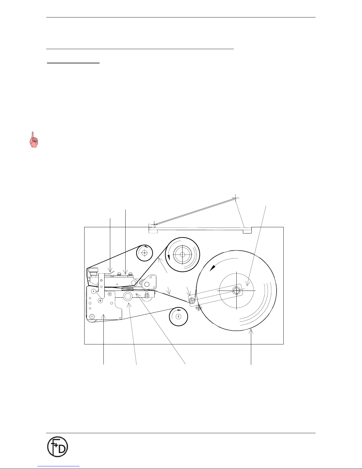
2.5 Insertion of Paper and Transfer Ribbon
Insertion of Paper
The label printer is suited to print onto thermal paper. Normal paper, plastic foil and metal foil can only be
printed by using the option transfer device. These materials are available on reels or adhesive labels.
1. Open the cover and remove the white paper guide disk.
2. Push reel onto wind off spindle.
3. Push paper guide disk back.
4. Unwind some label material or paper respectively and load the material into the right and left paper guide
while print head device is opened.
5. Adjust paper guide width by the black knurled screw. The label material should not be depressed down
by this action (leave approx. 0.5 mm play).
Notice: It is important that the distance between the paper and the mounting plate on the paper guide is
equal to that on the label reel. The reel can be moved easily. The paper guide disks should only press lightly
against the reels. Uneven wound or misaligned label reels lead to printing errors and paper jam.
The maximum diameter of the paper reels on the internal rewinder lies at 90 mm.
6. Hinge print head device down and secure.
Lock
Printer Device Upper
Paper Guide Disk
Printer Device Lower Knurl Screw Paper Guide
Label Reel
* Rewinder Device for
Label Base Material
* Optional
Label
Colour Layer
*Rewinder Device for
Transfer Ribbon
Tensioner
Page 7
User Manual ECO 200
Initial Start Up
F+D Feinwerk- und Drucktechnik GmbH
Kirchenstraße 38, D-69239 Neckarsteinach
Tel.: 06229 7000, Fax: 06229 70067
E-Mail: [email protected], Internet: http://www.fuddruck.de
7
Insertion of Transfer Ribbon
Printers equipped with the option „Transfer Device“, feature a wind off / wind on mechanism positioned
above the printer upper section (see diagram on previous page).
1. Push transfer ribbon reel onto winding device below operator panel.
2. Centre reel to print head.
3. Guide ribbon according to diagram on previous page below the opened printer device upper.
4. Wind transfer ribbon round rewinding device.
5. Insert clamp strap into the groove and hole.
6. Turn the rewinding device one full circle clockwise and thus tension the transfer ribbon.
7. Hinge printer device down and secure again.
Notice: The shiny side of the ribbon must point towards the thermal print head. The somewhat more dull
side is the colour layer, which must point towards the paper.
Synchronization
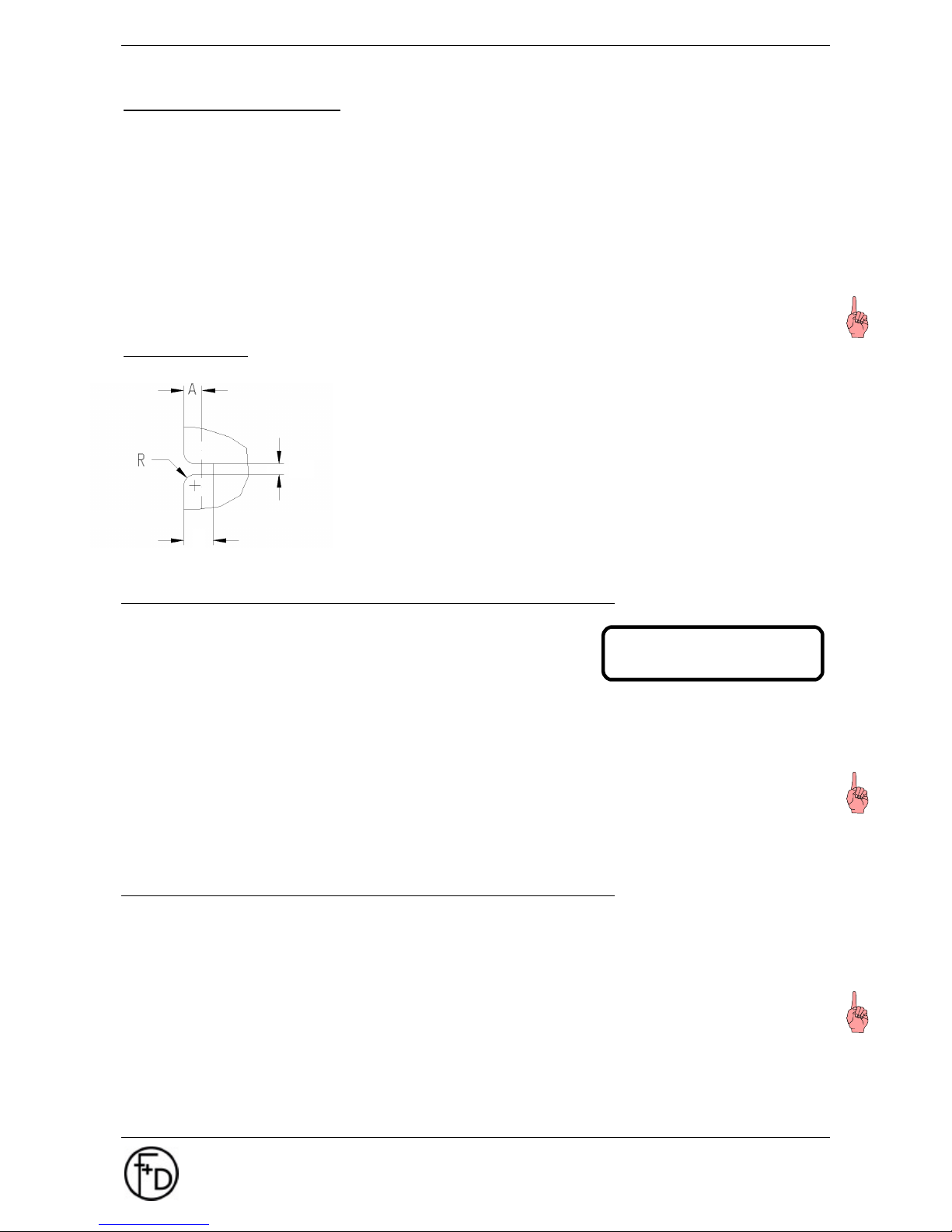
Recognition of label start is effected via scan-through light barrier and
requests synchronization marks between the labels. The synchronous
light barrier has a clearance A = 5 mm from the edge of the paper.
Therefore the depth (D) of the synchronization mark should be at least
6 mm from the left paper edge in order to have an edge radius (R) of
less than 3 mm. The width (W) has to be at least 1.5 mm. Label
distances or printed synchronization marks could also be recognized if
the sensor had been adjusted accordingly.
2.6 Printout of a Test Label
1. Switch printer on.
2. Put paper into the printer.
3. Go to menu Printer Infos / Labels
4. Depress the l - button in order to chose the label Firmenadresse.
5. Confirm your choice by depressing the SAVE - key.
The menu will be exited and the label will be printed, at the same time a black shape appears on the
LCD left of the "1" (in accordance to the set macro).
6. Press again PRINT-button and the test label will be printed.
Notice: Please check in advance
• Is thermal print head inserted?
• Is printer device upper closed?
• Is paper reel (and transfer ribbon) inserted?
2.7 Parallel Interface
In order to connect the parallel cable, align the wider side of the plug to the wider side of the printer
connector. Afterwards fasten the plug with the two existing clamps in order to produce a stable electrical
contact.
Then connect the cable to the computer (corresponding parallel interface).
Notice: Before connecting the cable, the printer and the PC have to be switched off.
D
ECO 200 ok ->g1
#0000
Page 8
8 User Manual ECO 200
Initial Start Up
F+D Feinwerk- und Drucktechnik GmbH
Kirchenstraße 38, D-69239 Neckarsteinach
Tel.: 06229 7000, Fax: 06229 70067
E-Mail: [email protected], Internet: http://www.fuddruck.de
2.8 Serial Interface
In order to connect the serial cable, align the wider side of the plug to the wider side of the printer connector.
Afterwards fasten the plug with the two existing screws in order to produce a stable electrical contact.
Then connect the cable to the computer (corresponding serial interface).
The serial interface also serves for communication with the PC, but it is slower than the parallel interface. By
using the keyboard you can set
Baud rate: 4800, 9600, 19200, 38400
Data bits: 7, 8
Stop bit: 1, 2 and
Parity: without, with (even, odd)
Protocol: without XON / XOFF, with XON / XOFF
Standard settings are printed in bold.
Notice: Before connecting the cable, the printer and the PC had to be switched off.
2.9 Transporting the Printer
1. Switch printer off.
2. Unplug carefully the mains cable and the interface cable (serial and/or Centronics-cable).
3. Use original packing material for transportation, where possible.
Notice: Before transporting the printer, all paper- and transfer ribbon rolls must be removed.
Page 9
User Manual ECO 200
Operating
F+D Feinwerk- und Drucktechnik GmbH
Kirchenstraße 38, D-69239 Neckarsteinach
Tel.: 06229 7000, Fax: 06229 70067
E-Mail: [email protected], Internet: http://www.fuddruck.de
9
3. Operating
3.1 Control Panel
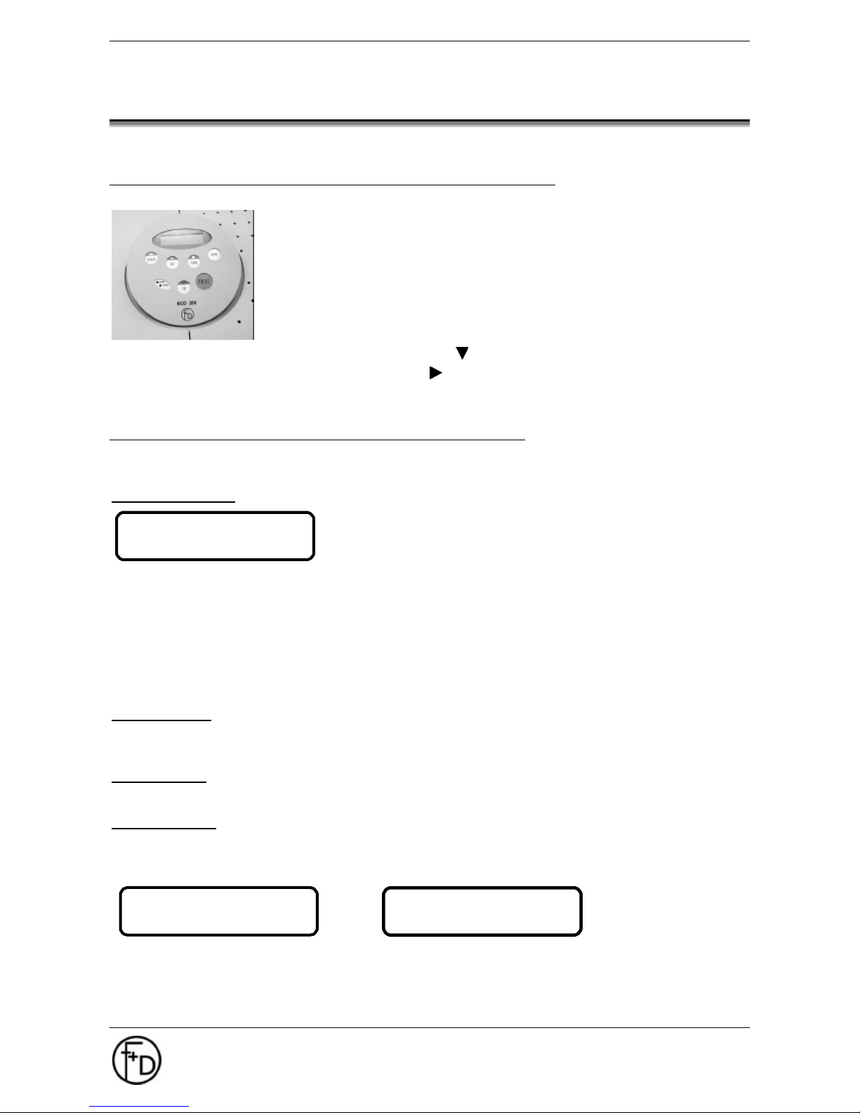
The control panel consists of
• LCD- Screen (2x16 digits)
• 2 LEDs (Power and Error)
• 6 keys:
PRINT- key
FF / SAVE - key
MENU- key
STATUS / - key
CUT / - key
CLEAR / l - key
3.1.1 LCD-Display
The information shown on the display depends on present operating mode of the printer. In total, 4 different
sub-screens can be opened.
Standard Screen:
This mode displays the actual short-status of the printer, which is of
interest during the printing process. This screen (see picture opposite)
should always be displayed when printer is switched on.
Meaning of the status symbols:
-> XON- status
| XOFF- status
no label set edited
n label set edited
1 Macro 1 active
# Number of labels, which still have to be printed by the actual label set.
Menu-Screen:
Will be opened, when MENU-key is depressed. Inside the menu structure, the upper line shows the main
menu and the lower line shows the sub-menu.
Error-Screen:
Is displayed by the printer in case an error incurred.
Status-Screen:
Will be displayed when STATUS-key is depressed. By depressing the key again, the second part of the
status-window will be displayed. By depressing the key anew, the standard-screen will be displayed or in
case of an error the error listing is displayed. (see Software Manual: Status Message)
1. Status-Screen 2. Status-Screen
ECO 200 ok -> 1
#0000
DEVICE # 1008
31-10-2001 D ECP
ECO 200 S02/V2.02
=00#0000*0131072
Page 10
10 User Manual ECO 200
Operating
F+D Feinwerk- und Drucktechnik GmbH
Kirchenstraße 38, D-69239 Neckarsteinach
Tel.: 06229 7000, Fax: 06229 70067
E-Mail: [email protected], Internet: http://www.fuddruck.de
3.1.2 Power- and Error-Display
Power-Display:
This display is green and lights up in case the mains switch of the printer is switched on.
Error-Display
This display is red and lights up or blinks in those cases the error-screen is active.
3.1.3 Keys
PRINT key
Of the actual label set one label will be printed.
FF key
Transports the paper through the printer without printing and synchronizes to print start.
MENU key
The menu-screen will be displayed. This gives the user the possibility to check the set printer functions or
change them respectively. The menu will be exited by depressing the same key again.
By depressing this key for a longer time period, that particular part of the menu can be skipped to, where the
last skip back took place.
During a print job, this can be stopped by depressing the key for a while, and depressing the key again
enables finishing the print job.
STATUS key
The status-screen will be displayed. In case of an error, this key (depress key 2x) displays the 2nd statusscreen with up to 8 error codes. The menu will be exited by depressing the same key again.
CUT key
Should a cutting device be available, this can be activated by depressing the Cut-key.
CLEAR key
Functions only when error-screen is opened. By means of CLEAR-key the displayed warning-message can
be erased. In case several errors are indicated at the same time, only the warning-message with the highest
priority at that time will be displayed. The CLEAR-key can only be depressed for that amount of time until all
warning-messages are displayed or erased respectively.
ERROR- and HARDWARE- messages cannot be erased.
Page 11
User Manual ECO 200
Operating
F+D Feinwerk- und Drucktechnik GmbH
Kirchenstraße 38, D-69239 Neckarsteinach
Tel.: 06229 7000, Fax: 06229 70067
E-Mail: [email protected], Internet: http://www.fuddruck.de
11
3.2 Main Menu Mode
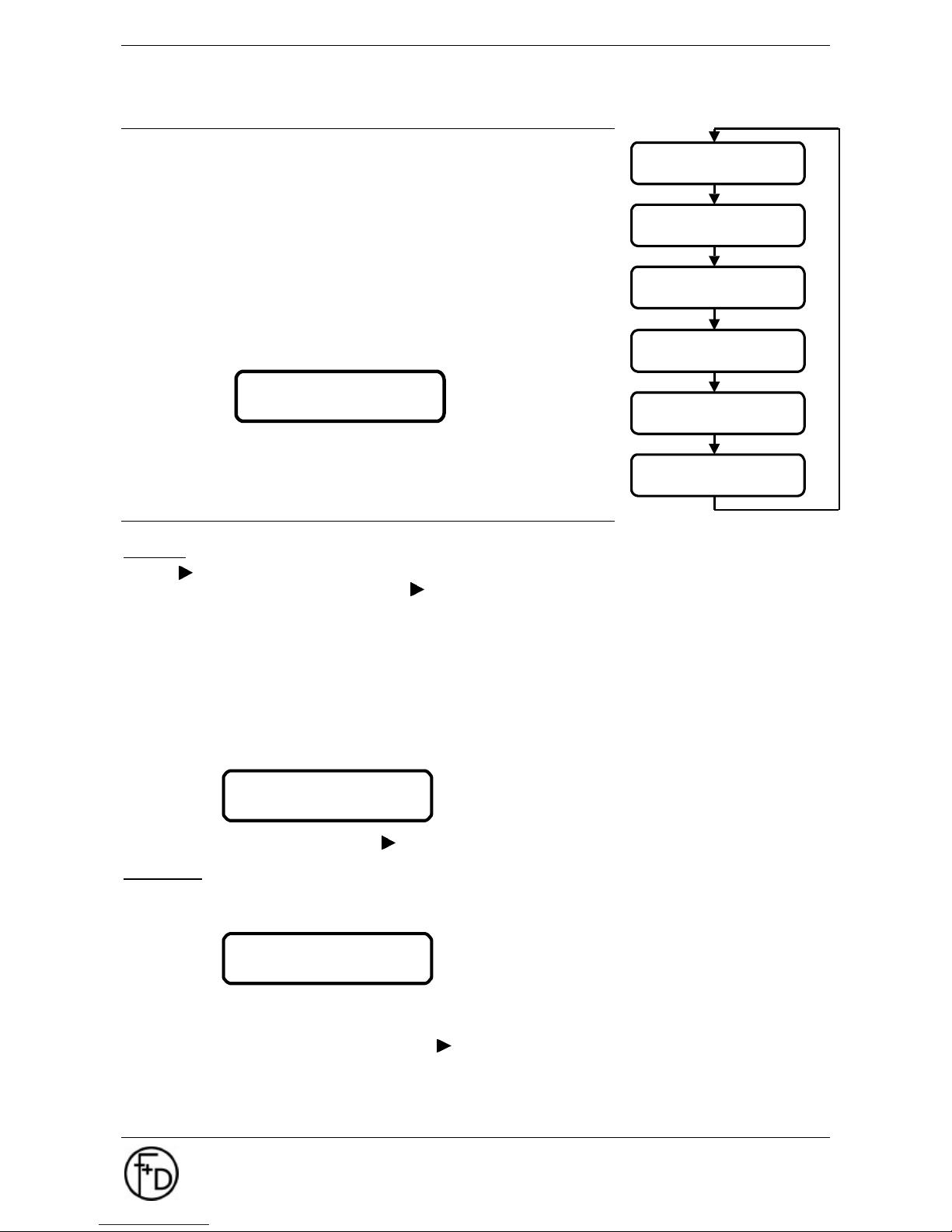
This menu is called-up by depressing the MENU-key. Depressing the
key for only a short time, skips to the start of the menu. Depressing the
key longer, skips directly to that option of this menu where it has been
exited from last time.
The menu is exited by depressing the MENU-key.
After call-up of the menu, the menu display is shown and the functions
of the keys are different. The first line of the LCD-screen displays the
first main menu.
Scrolling the main menu is effected with the -key. Main menus are
always displayed in the first LCD-line and also in capital letters.
In this example the main menu PRINTER SPECS. is indicated.
The menu can be exited by depressing the MENU-key.
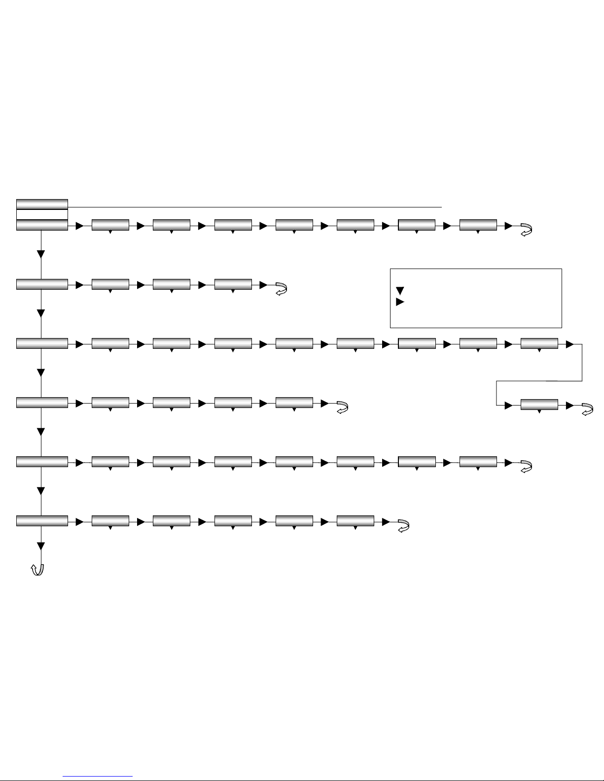
3.3 Sub-Menu Mode
General
With the -key the displayed main menu can be skipped. In order to display the various sub-menus of the
chosen main menu, continue to depress the -key.
Sub-menus, as long as they are not chosen, are displayed in the 2nd LCD-line in capital- as well as small
letters.
For this example the main menu LABEL DATA has been chosen and the sub-menu 'Number of Labels'. The
menu can be exited by depressing the MENU-key.
By depressing the key l the displayed sub-menu is chosen. In order to display the various options of a submenu, the key l is depressed furthermore. Current active settings are marked with a hook (√) and most of
the time also displayed as first option.
For this example the main menu LABEL DATA has been chosen and the sub-menu 'Number of Labels'.
The menu can be exited afterwards via -key and then by depressing the MENU-key.
SAVE key
When an option is chosen, it can be saved by depressing the key SAVE and stored in the current macro. A
confirmation will be displayed for about 2 seconds on the screen:
After storage this menu option will automatically be exited.
In case the stored value should be checked afterwards, this can be effected by depressing the 2-key.
The menu can then be exited by depressing the -key and then the MENU-key.
PRINTER SPECS.
LABEL DATA
Copies
-------------------------
-------------------------
MACRO NAVIGATER
LABEL DATA
PRINT PARAMETERS
CHARACTER / LCD
PRINTER SPECS.
PRINTER INFOS
Page 12
12 User Manual ECO 200
Operating
F+D Feinwerk- und Drucktechnik GmbH
Kirchenstraße 38, D-69239 Neckarsteinach
Tel.: 06229 7000, Fax: 06229 70067
E-Mail: [email protected], Internet: http://www.fuddruck.de
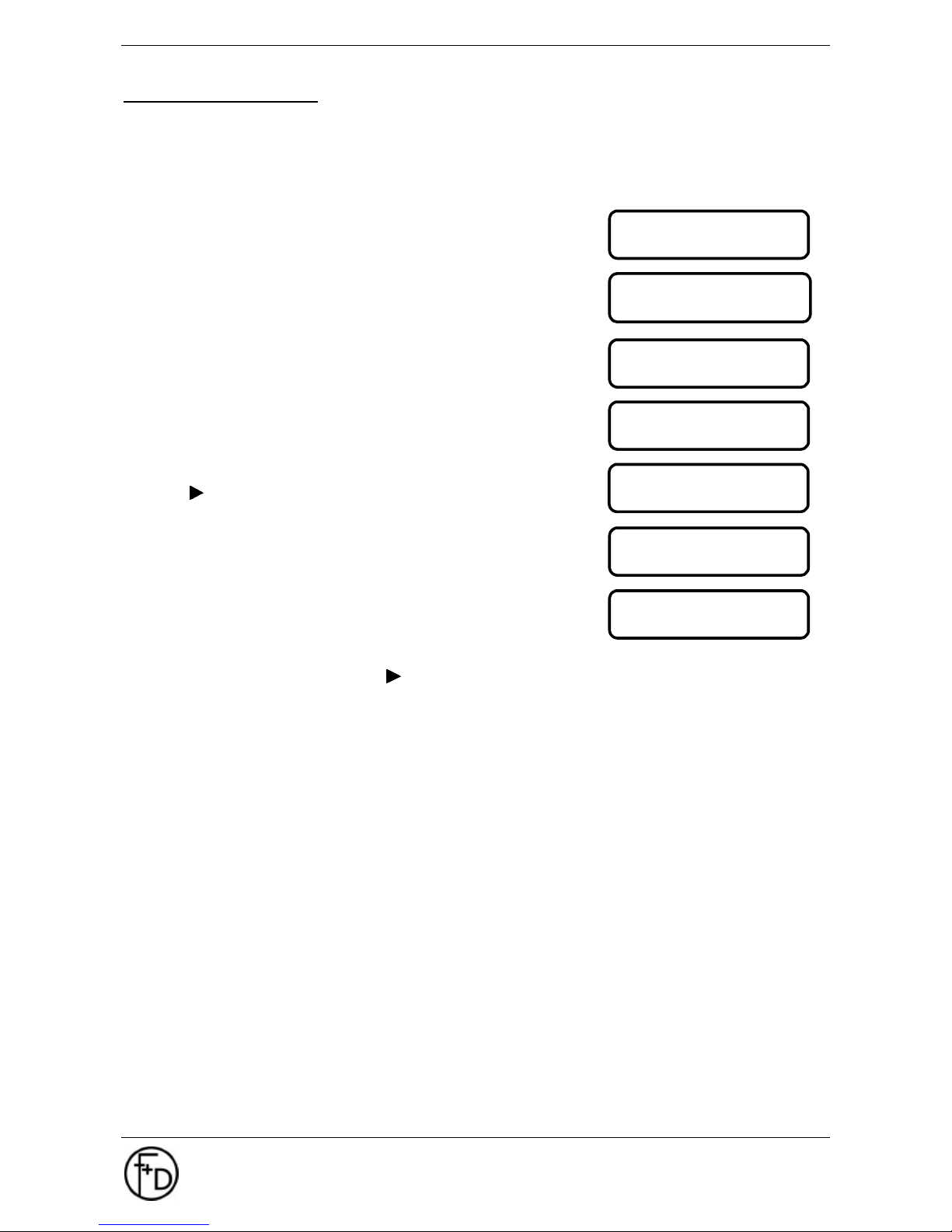
Input of numerical values
A menu option can also mean a further choice of different options. Alternatively at this point a numerical
value could be expected to be input according to the actual menu. The ECO 200 places a simple editor at
your disposal.
Example:
Change the number of labels from 10 to 60!
Input: Key l to call-up editor
Input: key l for first numerical position
Input: key l for next numerical position
Input: key l for next numerical position
Input: key for actual digit depress key 6x
Input: key l for next numerical position
Input: key l to exit editor
In case the number is incorrect, the editor can be called again by depressing the l-key once again. The
option is exited either by depressing the - key or the SAVE-key.
Copies
0010
Copies
< 0 . . . >
Copies
< 0 0 . . >
Copies
< 0 0 0 . >
Copies
< 0 0 6 . >
Copies
< 0 0 6 0 >
Copies
0 0 6 0
Page 13
3.3.1 Menu and Parameters
PRINTER INFOS
ECO 200 ok
press MENU
warnings
insert data
l
acknowledge
l display only
l ignore
l #70 ignore
byteam.:XXXXH
logos
print - status
l
FDLogo
fonts
l
COURI06F -
COURI14F
l ARIAL08F ARIAL22F
barcodes
labels
l
EAN 8/13
l C_2o5_I
l C_39
l C_128
l EAN128
l PDF417
l
Firmenadresse
LABEL DATA
copies
image width
l
0000l 0800 dot 100 mm
image height
image abort.
l
0478 dot 60 mm
l
000 dot 002 mm
dispersing pos.
l
060 dot 8 mm
paper end at..
paper jam at..
l
80 dot 10 mm
l
4000 dot 500 mm
TOF-offset
l
50 dot - 50
PRINT PARAMETERS
heating time tph
l
+30% to –30%
printing speed.
synchronisation
l
75 mm/s -
200 mm/s
l
no (with FF)
l no (no FF)
l yes (with FF)
l yes (no FF)
l yes (AUTO FF)
Queue process
l
no
l yes
PRINTER SPECS.
printer - mode
l
no print key
l with print key
aut.papersensor
l
start?
man.papersens
l
Value: 22 LED -
CHARACTER / LCD
schedule
country
l
ANSI
l ASCII
l multilingual
l
USA
l England
l Germany
l Denmark
l France
l Sweden
l Italy
l Spain
l Norway
Update FlashDa
l
Send Data
keys- and character explanation
-key: leaf through the main menu
-key: leaf through the sub menu
l -key: select option
l default
boot-macro 0-3
init macro
l
Macro 1
l Macro 2
l Macro 3
l Macro 0
l
macro 0->1
l macro 0->2
l macro 0->3
copy macro
l
macro 1->2 |1->3
l macro 2->3 |2->1
l macro 3->1 |3->2
MACRO NAVIGATER
cutting pos..
l
158 dot 20 mm
RS232
l
4800 Baud
l 9600 Baud
l 19200 Baud
l 38400 Baud
l 7 data bits
l 8 data bits
l 1 stop bit
l 2 stop bits
l no parity
l even parity
l odd parity
l no XON/XOFF
l with XON/XOFF
dispersing ...
l
no
l with print key
l label taken
cutter
l
no
l yes
l yes, always
transfer
l
not present
l present
language
l
English
l French
l German
scrolling
l
no
l yes
Page 14
14 User Manual ECO 200
Operating
F+D Feinwerk- und Drucktechnik GmbH
Kirchenstraße 38, D-69239 Neckarsteinach
Tel.: 06229 7000, Fax: 06229 70067
E-Mail: [email protected], Internet: http://www.fuddruck.de
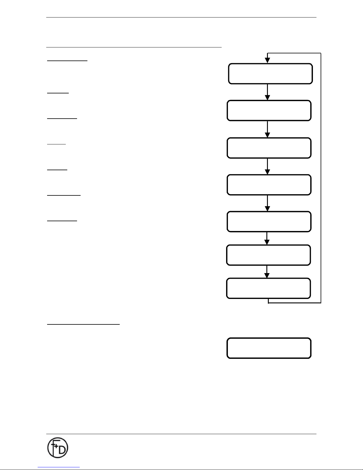
3.3.2 Printer Infos
Print - Status:
Print out of all parameter to be set. Image width and image height must
be set to ≥ 54 mm (648 dots) each. You can print the print-status by
using the l - key.
Labels:
All label sets stored in the printer will be displayed here. You can print
the select label by using the SAVE-key.
Barcodes:
All barcodes stored in the printer will be displayed here. You can print
the select barcode by using the SAVE-key.
Fonts:
All fonts stored in the printer will be displayed here. You can print the
select font by using the SAVE-key.
Logos:
All logos stored in the printer will be displayed here. You can print the
select logo by using the SAVE-key.
Insert data:
Amount of data submitted to the ECO 200. The amount is displayed in a
hexadecimal number.
Warnings:
Details of warnings including confirmation possibilities
Print-out stored label set
Barcodes, fonts, logos and labels stored in the printer can be printed
out easily and is described below:
4. Go to menu Printer Infos / Labels
5. Depress the l - button in order to chose the desired label.
6. Confirm your choice by depressing the SAVE - key.
The menu will be exited and the label will be printed, at the same time a black shape appears on the
LCD left of the "1" (in accordance to the set macro).
7. Depress the PRINT - key again for a short time in order to print a further label.
ECO 200 ok ->g1
#0000
PRINTER INFOS
warnings
PRINTER INFOS
insert data
PRINTER INFOS
barcodes
PRINTER INFOS
fonts
PRINTER INFOS
labels
logos
PRINTER INFOS
PRINTER INFOS
print-status
Page 15
User Manual ECO 200
Operating
F+D Feinwerk- und Drucktechnik GmbH
Kirchenstraße 38, D-69239 Neckarsteinach
Tel.: 06229 7000, Fax: 06229 70067
E-Mail: [email protected], Internet: http://www.fuddruck.de
15
3.3.3 Macro Navigater
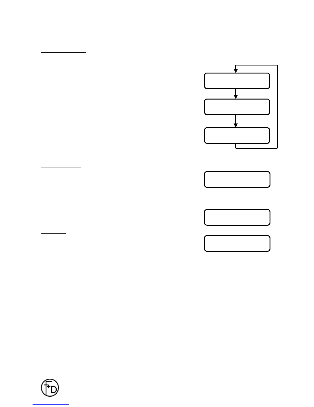
What is a macro?
With the printer a macro means a fixed set of printer characteristics, such as transfer printing, heating time,
cutting device, etc.
All parameter, which are changeable in the menu of the ECO 200 , can
be combined as a macro. Otherwise they will be lost when the printer is
switched off.
The ECO 200 contains 3 macros, numbered from 1 to 3. With these
macros the printer can chose between 3 different fixed configurations.
The macros are stored in the printer. The content of this memory will
remain, even if the printer is switched off.
As soon as the printer is switched on, that macro set in the boot macro
will automatically be loaded into the work area. Thus the printer knows
all printing options when it is switched on.
Macro 0 has been preset by the manufacturer as default macro. This
cannot be changed.
Macros 1,2, and 3 also contain preset values like macro 0, but these
can be changed by the user.
The loaded macro will be displayed in the standard display (1st LCD-line, 16th position).
Boot-Macro 0-3
The actual boot macro will be marked with a hook or displayed in the
standard display respectively. By depressing the l - button the desired
macro is selected and chosen by depressing the SAVE-key. With the
change of the boot-macro the printer is automatically restarted,
afterwards the new macro is active immediately.
Copy Macro
Around the content of the current macro in another macro to take over
you can copy a macro. For this select the respective menu option and
store it with the SAVE-key. Thus the macro is stored.
Init Macro
With it you put back the macro 1, 2 or 3 on the default values
of macro 0.
MACRO NAVIGATER
boot - macro 0-3
MACRO NAVIGATER
copy macro
MACRO NAVIGATER
init macro
boot - macro 0-3
√
macro 1
copy macro
macro 1 -> 2
init macro
0 -> 1
Page 16
16 User Manual ECO 200
Operating
F+D Feinwerk- und Drucktechnik GmbH
Kirchenstraße 38, D-69239 Neckarsteinach
Tel.: 06229 7000, Fax: 06229 70067
E-Mail: [email protected], Internet: http://www.fuddruck.de
3.3.4 Label Data
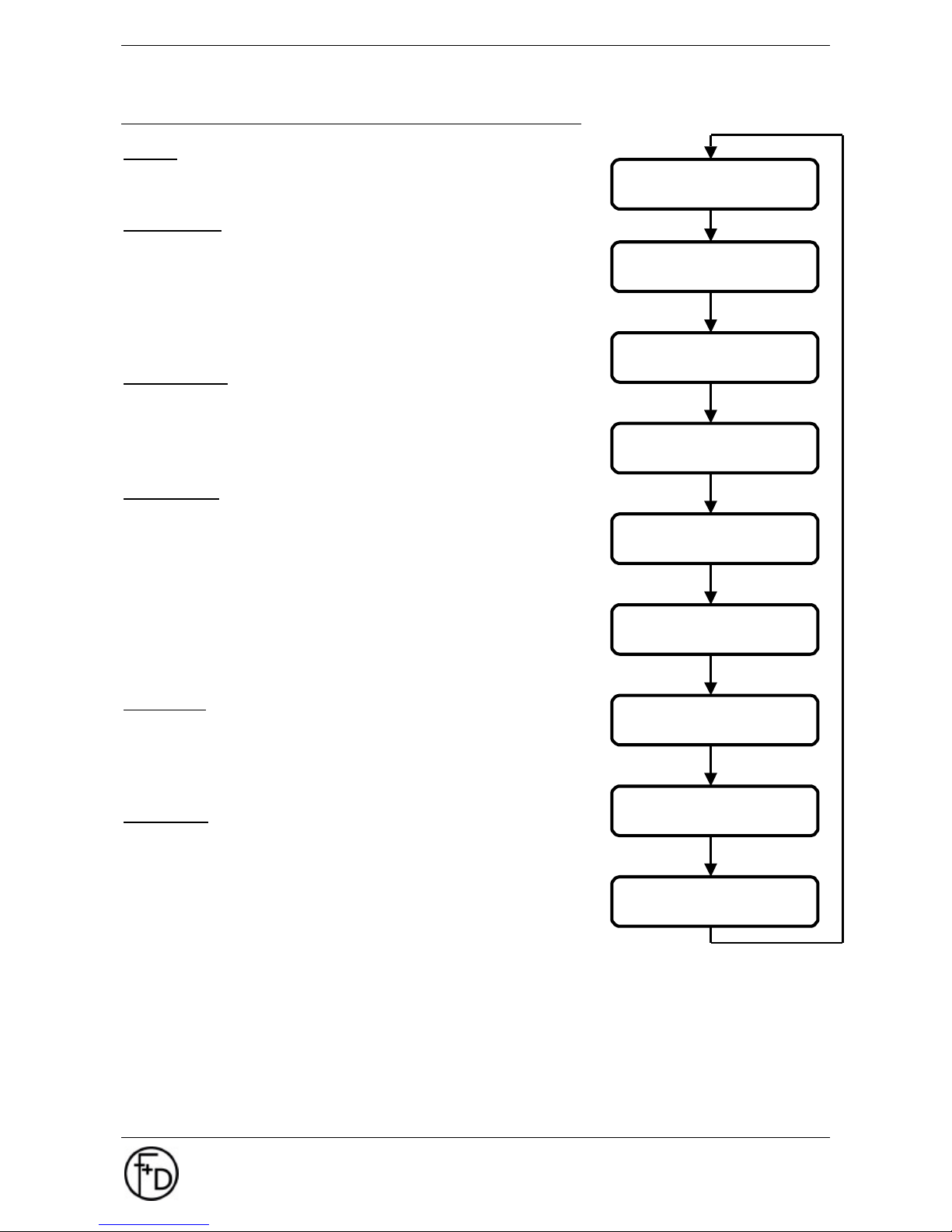
Copies
- 0000 - 9999
Number of labels to be printed
Image Width
- 0000 - 0896 dots
Image Width determines the width of the print area.
Parameter: d = image width * 8 / mm in number of dots
minimum width = 8 mm (d=64), maximum width = 108 mm (d=864)
The value for the image width can at any time be smaller than the real
label format. The resulting print area will thus be in image middle.
Image Height
- 0000 - 4000 steps
Image Height determines the height of the print area.
Parameter: d = image height * 8 / mm in number of motor steps
minimum height = 10 mm (d=80), maximum height = 500 mm (d=4000)
Image Abort
- 0002 – 6000 steps
The Image Abort forces an abort of the printing process. This is
sensible, if at the end of an image area there are only blanks. The
image abort encourages the image creation at high printing speeds.
Parameter: d = image abort * 8 / mm in number of motor steps
automatically image abort (d = 0000):
Display: 0000 dot 002
The Printer automatically find out the image abort to get the best
printing.
Paper End
- 000 – 999 steps
In case that within the set step no new label is recognized, the error
message Paper End will be displayed.
Parameter: d = paper end * 8 / mm in number of motor steps
Paper Jam
- 0000 – 4000 steps
In case that within the set step no paper end is recognized, the error
message Paper Jam will be displayed.
Parameter: d = paper jam * 8 / mm in number of motor steps
Without Label Synchronization:
There will be no check if paper jam incurred.
With Label Synchronization:
The input value must be larger than the label height (in dots), otherwise an unauthorized paper end - error
message will be given.
LABEL DATA
copies
LABEL DATA
image width
LABEL DATA
image hight
LABEL DATA
image abort
LABEL DATA
paper end at..
LABEL DATA
paper jam at..
LABEL DATAv
TOF-Offset
LABEL DATA
dispensing pos.
LABEL DATA
cutting pos.
Page 17
User Manual ECO 200
Operating
F+D Feinwerk- und Drucktechnik GmbH
Kirchenstraße 38, D-69239 Neckarsteinach
Tel.: 06229 7000, Fax: 06229 70067
E-Mail: [email protected], Internet: http://www.fuddruck.de
17
Dispensing Position
- 000 - 999 steps
To the position of the start of the label an additional forward feed is effected in order to remove the
previously printed label.
Parameter: d = dispensing position * 8 / mm in number of motor steps
After each dispensing operation and after the label has been removed, the next label will be re-positioned to
the start of the label.
The dispensing position will be ignored should the cutting device be logged-on.
Cutting Position
- 000 - 999 steps
To the position of the start of the label an additional forward feed is effected in order to cut the previously
printed label.
Parameter: d = cutting position * 8 / mm in number of motor steps
The cutting position describes the distance between the thermal print head and the cutting device. This
normally lies at 19.8 mm (d=158). By changing this value the cutting position can be moved.
After each cutting operation and before the next printing process, the label will be re-positioned to the start of
the label.
The cutting position will only be considered, should cutting device be logged-on.
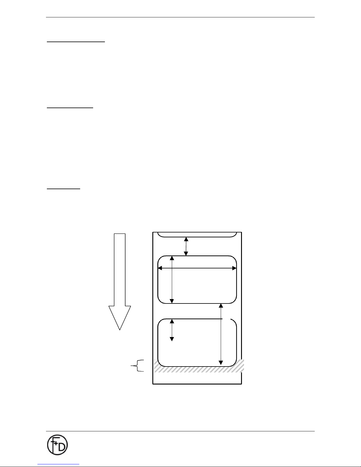
TOF-Offset
- 00 - 99 steps – 50
Distance between start of printout to label edge.
d = number of input steps (motor steps)
image heigth
TEXT
image abord
TOF-offset
paper end min.
image width
99
0
print direction
thermal print head with print
Page 18
18 User Manual ECO 200
Operating
F+D Feinwerk- und Drucktechnik GmbH
Kirchenstraße 38, D-69239 Neckarsteinach
Tel.: 06229 7000, Fax: 06229 70067
E-Mail: [email protected], Internet: http://www.fuddruck.de
3.3.5 Print Parameters
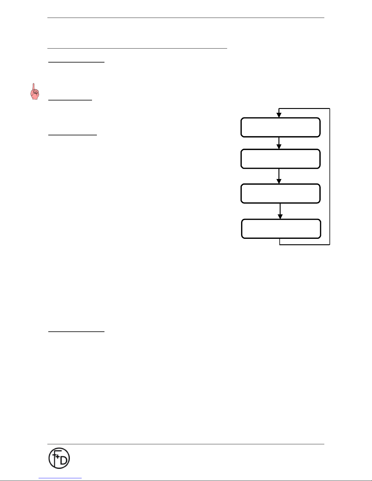
Heating Time TPH
- from -30% to +30% in steps of 5%
By this the blackening intensity of the paper is set. The higher this value, the higher the intensity of black.
Notice: The higher this value, the higher the loading on the thermal print head.
Printing speed
Printing speed determines the transportation speed of the label paper
within the printing range.
- 75, 100, 125, 150, 175 or 200 mm/s
Synchronization
- no ( with FF)
This setting is required when using endless paper. No label
synchronization will be effected. FF causes a forwarding of the paper
according to the set image height. Paper end will be detected, paper
jam not. When switching the printer on, a forward feed of 1 label will be
effected.
- no (without FF)
As with the previous point, but when switching the printer on, no forward
feed will be effected.
- yes (with FF)
This setting is necessary for label paper with index marking. Each label
will be synchronized to the label start. FF will effect a forward feed to
the next label. Paper jam as well as paper end will be checked subject
to the input values. When switching the printer on, a forward feed will be
effected to the next possible label. With labels smaller than 60 mm,
more than 1 label will be forward fed.
- yes (without FF)
As with the previous setting, but when switching printer on, no labels will be lost, as no forward feed takes
place. The PRO 300 assumes that when the printer is switched on, the label paper is already positioned
correctly. If this is not the case, positioning can be effected by depressing the FF-key several times.
- yes (AUTO FF)
The printer autonomously determines image height, paper jam and paper end. Afterwards positioning to
label start (or dispensing position) will be effected. Labels up to a maximum length of 50 cm will be
supported whereas the space between the labels should not be wider than 10 cm. Larger distances between
the labels will cause a paper-error-message. Normally at least 2 labels have to be transported unprinted.
Queue Processing
- no
- yes
Normally the printer parameter can either be sent before or after the label set. Thus giving the possibility of
subsequent changes of the settings. In case there are more label sets in the input memory queue, no definite
allocation of the printer parameter between the 2 label sets is possible any more. Thus the printer parameter
of the following label set could, circumstances permitting, influence the actual label. In order to avoid this, the
following menu points must be observed:
Menu PRINT PARAMETERS / sub-menu Queue Processing chose option yes
By depressing the SAVE-button the option is saved and, if required, be stored in the macro.
With this setting printer parameter will only be processed before the label set. Only after the desired number
of labels is printed, the evaluation of the following printer parameter including the new set of labels takes
place.
PRINT PARAMETERS
heating time tph
PRINT PARAMETERS
printing speed
PRINT PARAMETERS
synchronisation
PRINT PARAMETERS
Queue process
Page 19
User Manual ECO 200
Operating
F+D Feinwerk- und Drucktechnik GmbH
Kirchenstraße 38, D-69239 Neckarsteinach
Tel.: 06229 7000, Fax: 06229 70067
E-Mail: [email protected], Internet: http://www.fuddruck.de
19
3.3.6 Printer Specs.
Printer - Mode
- without Print key
- with print key
Printing is only possible by depressing the PRINT-key.
Automatic paper sensor
- start ?
When switching to another label paper there might incur problems with synchronization, should both paper
types be very different. In order to guarantee a reliable synchronization, it might be necessary to carry out
the following option.
Before starting the printout the paper sensor has to be positioned at a part of the label which has not yet
been printed. In the case of an incorrect measuring the notice ERROR appears on the screen. In order that
the printer retains the change made when subsequently switched on, the new information has to be
committed to memory. For that you have to select the option manual paper sensor and store it with the
SAVE-Key.
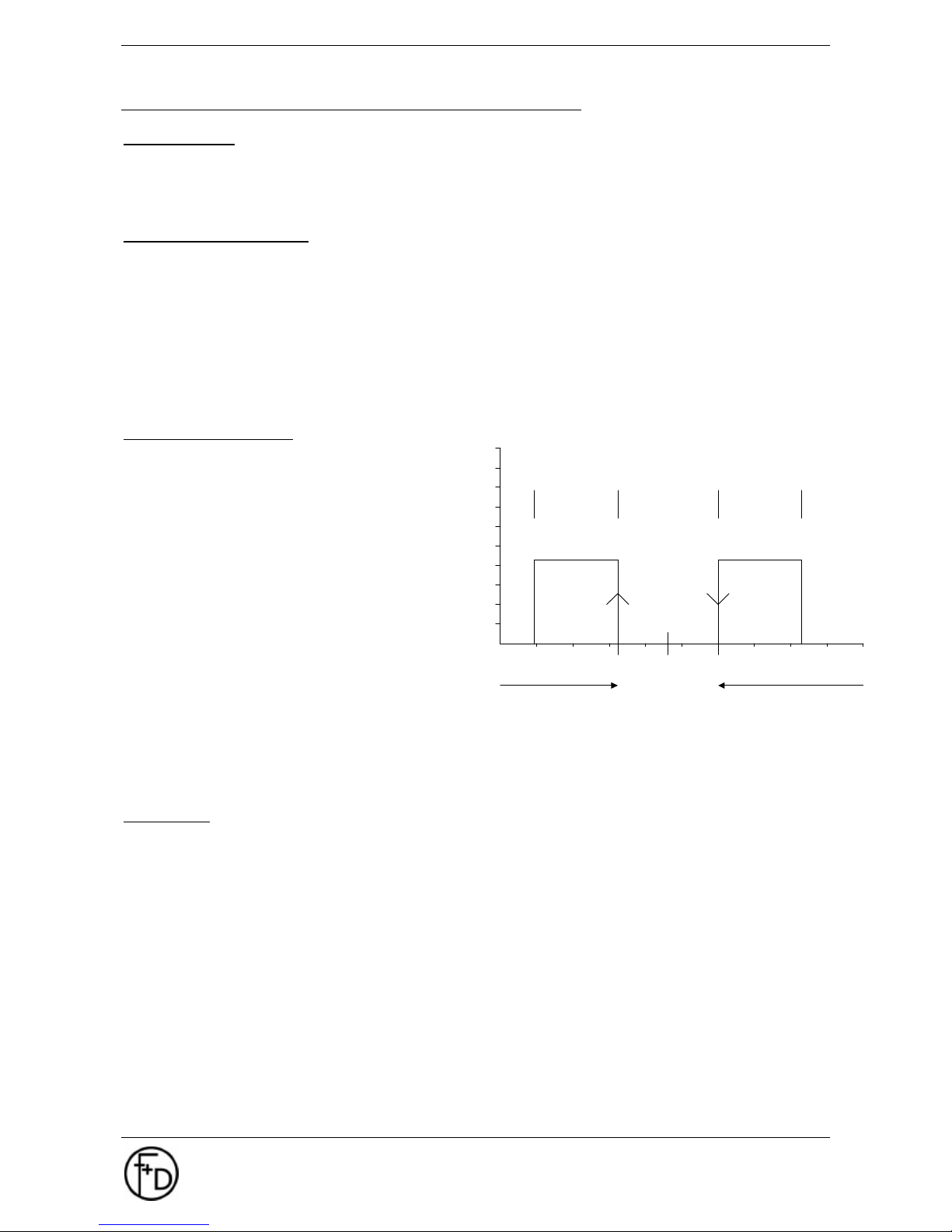
Manual paper sensor:
- 0 - 127 LED
For determination of the optimum sensor
adjustment.
STATUS-button - decrease sensor current
CLEAR-button - increase sensor current
Proceeding:
8. The label material has to be positioned with the
carrier in the area of the paper sensor.
9. The point of switching A determine: of - after *
10. The label has to be positioned in the area of the
paper sensor
11. Point of switching B determine: of * after –
12. The correct sensor value Z is the mean value of
the two measurements.
Dispensing
When dispensing labels, the label has to be transported after printing so far, so that it can be taken out
easily. Time of taking the label out will either be monitored by label-taken (option) or by means of operation
of the print-key. Dispensing position 0 corresponds to the positioning at the start of the label. In order to be
able to take the previous label, the value for the dispensing position has to be increased.
- no
- with print key
After the print job is finished the paper will be reset to the dispensing position for enabling the take- or tearoff of the label. After pressing the print key it turns again back in the printing position and the next print order
can be carried out.
- with label taken
The label-taken-device can be installed as an option. The device ensures that the next label will only be
printed if the previous one has been taken out. A dispensing position > 0 always means, that the following
label has to be repositioned before printing takes place.
Logging-on of the label-taken-device is only possible – label taken without the cutting device. The dispensing
position will be ignored in case the cutting device is logged-on.
switching points
sensor current
-
*
hysteresis hysteresis
-
*
0 127
C
L
C : carrier material
L : label
A : measuring point 1
B : measuring point 2
Z : ideal value
* : scan material
- : do not scan material
A Z B
Z = (A+B) / 2
1st measuring 2nd measuring
Page 20

20 User Manual ECO 200
Operating
F+D Feinwerk- und Drucktechnik GmbH
Kirchenstraße 38, D-69239 Neckarsteinach
Tel.: 06229 7000, Fax: 06229 70067
E-Mail: [email protected], Internet: http://www.fuddruck.de
Cutting Device
Separating labels by cutting, a cutting device (option) must be installed.
- no
Should a cutting device be connected, but not logged-on, the logging-on
will be effected automatically when switching the printer on.
- yes
The label will always be synchronized to the TOF-position. Thus, during
a print job no forward-/backward-positioning has to be effected. The
motor can run between 2 labels in brakeless mode.
By means of ESC-k-sequence a cutting operation at the end of the print
job can be activated.
Furthermore, the cutting device can also be triggered via the CUT-key.
The dispensing position will be ignored in case the cutting device is
logged-on.
Notice: When single labels should be cut off it is important that
each label has a minimim height of 25 mm.
- yes, always
Each label within a print job should be cut. After the printing of a label
the cutting position will be driven to, cut and only before the next
printout takes place the TOF-position will be re-positioned.
Transfer
Transfer can be applied in combination with all other components.
- not present
- present
In case transfer is logged-on, a monitoring of the transfer ribbon is
effected as well as the drive of the transfer ribbon rewinding device.
- automatically
In each case of forward feed as well as when switching the printer on,
the presence of the transfer ribbon is interrogated. In case the transfer
ribbon is available, the transfer is automatically logged-on, otherwise
the transfer is logged-off.
RS232
- 4800, 9600,19200, 38400 baud
- 7 data bits, 8 data bits
- 1 stop bit, 2 stop bits
- without parity, even parity, odd parity
- without XON/XOFF, with XON/XOFF
Page 21
User Manual ECO 200
Operating
F+D Feinwerk- und Drucktechnik GmbH
Kirchenstraße 38, D-69239 Neckarsteinach
Tel.: 06229 7000, Fax: 06229 70067
E-Mail: [email protected], Internet: http://www.fuddruck.de
21
3.3.7 Character / LCD
Schedule
- ANSI
- ASCII
- multilingual
Country
- USA
- England
- Germany
- Denmark
- France
- Sweden
- Italy
- Spain
- Norway
- Netherlands
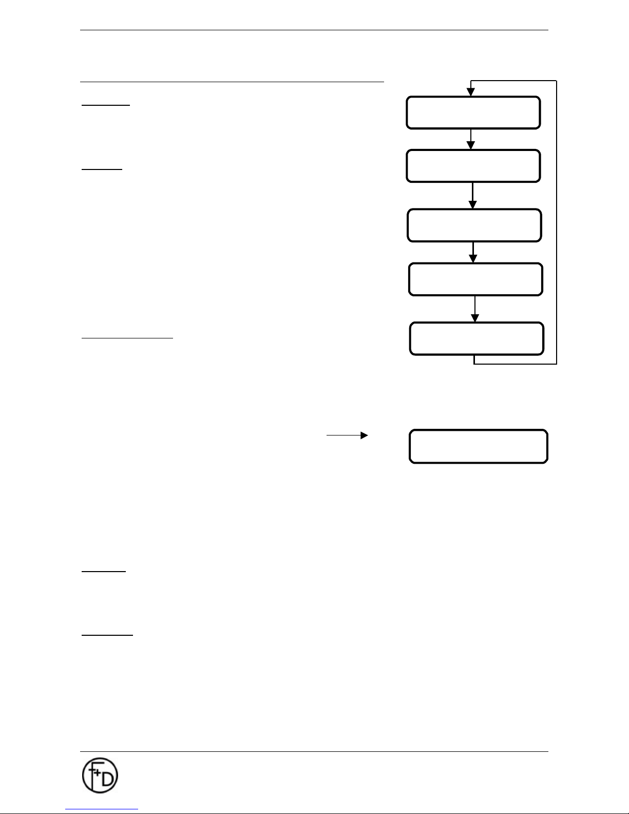
Update Flashdata
Here, logos and fonts can be store in the printer. The data is transferred
via serial or parallel interface.
For the conversion and implementation of logos the tool FDLogo can be
used. This is available on the homepage (www.FuDdruck.de).
1. Connect the printer via the parallel interface to the LPT-port of the PC.
2. Change to the menu CHARACTER/LCD / Update FlashData.
3. Activate the Update-mode by pressing the l - key.
4. In the display the following message will be shown
5. Data to be transmitted has to be prepared for the printer.
6. Activate the MS-DOS mode at the PC.
7. Now new data can be transmitted with the command line
copy/b file name lptx
Example: copy/b logos upd lpt1 <Enter>
via MS-DOS to the printer.
8. During the transmission process the message `....BUSY....´ will be displayed.
9. After successful transmission the printer states `....READY....´
10. The data is now firmly stored in the printer.
Scrolling
The menue text will be pushed in from aside
- no
- yes
Language
language to choose from menu CHARACTER / LCD
- german
- english
- french
* FLASH – DATA *
Send Data
CHARACTER / LCD
schedule
CHARACTER / LCD
country
CHARACTER / LCD
Update FlashData
CHARACTER / LCD
scrolling
CHARACTER / LCD
language
Page 22
22 User Manual ECO 200
Maintenance
F+D Feinwerk- und Drucktechnik GmbH
Kirchenstraße 38, D-69239 Neckarsteinach
Tel.: 06229 7000, Fax: 06229 70067
E-Mail: [email protected], Internet: http://www.fuddruck.de
4. Maintenance
4.1 Ribbon- and Paper-Changing
Change the paper or transfer ribbon respectively as described under 2.5.
4.2 Cleaning of the Thermal Print Head
Depending on the application- as well as the environmental- conditions of the thermal printer, the print head
must be cleaned every 10 to 20 working hours.
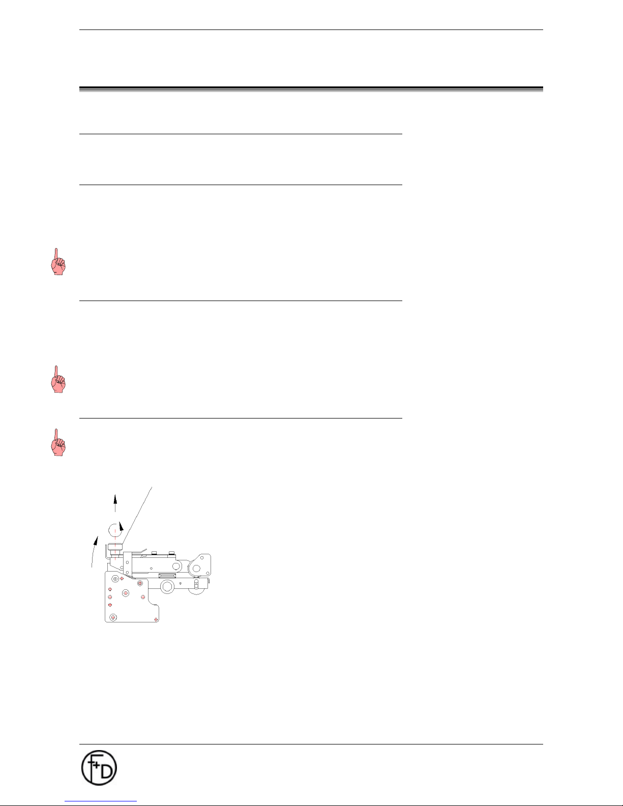
1. Switch printer off.
2. Release the print head upper and rotate upwards
3. Wipe with a spirit dampened cloth several times smoothly over the printing
Notice: Do not use any hard or sharp-edged objects.
4.3 Cleaning of the Feed Rollers
Above all paper and dust particles stick to the feed rollers, and have to be removed.
1. Switch printer off.
2. Release the print head upper and rotate upwards.
3. Clean feed roller with spirit and bobble free cloth.
4. After the rollers are dry, hinge print head device down and latch.
Notice: Do not use acetone or any other solvents.
4.4 Changing of Thermal Print Head
Notice: The thermal print head is a sensitive (mechanical, electronic and electro-static) component. Do not
use any sharp-edged items, and take care that you are not electro-statically charged. Electrostatic charges
can damage the thermal print head, therefore it is absolutely necessary to execute a charge equalization in
advance..
1. Switch printer off and unplug mains plug.
2. Release the print head upper and rotate upwards.
3. Unlock knurled screw in the middle of the print head upper
and pull print head forwards.
4. Disconnect cables.
5. Fit the new thermal print head. The thermal print head is preassembled onto an adapter and also pre-adjusted.
6. Connect cables to new thermal print head. Here, the correct
positioning of the connector has to be paid attention to.
Knurled screw
Page 23
User Manual ECO 200
Maintenance
F+D Feinwerk- und Drucktechnik GmbH
Kirchenstraße 38, D-69239 Neckarsteinach
Tel.: 06229 7000, Fax: 06229 70067
E-Mail: [email protected], Internet: http://www.fuddruck.de
23
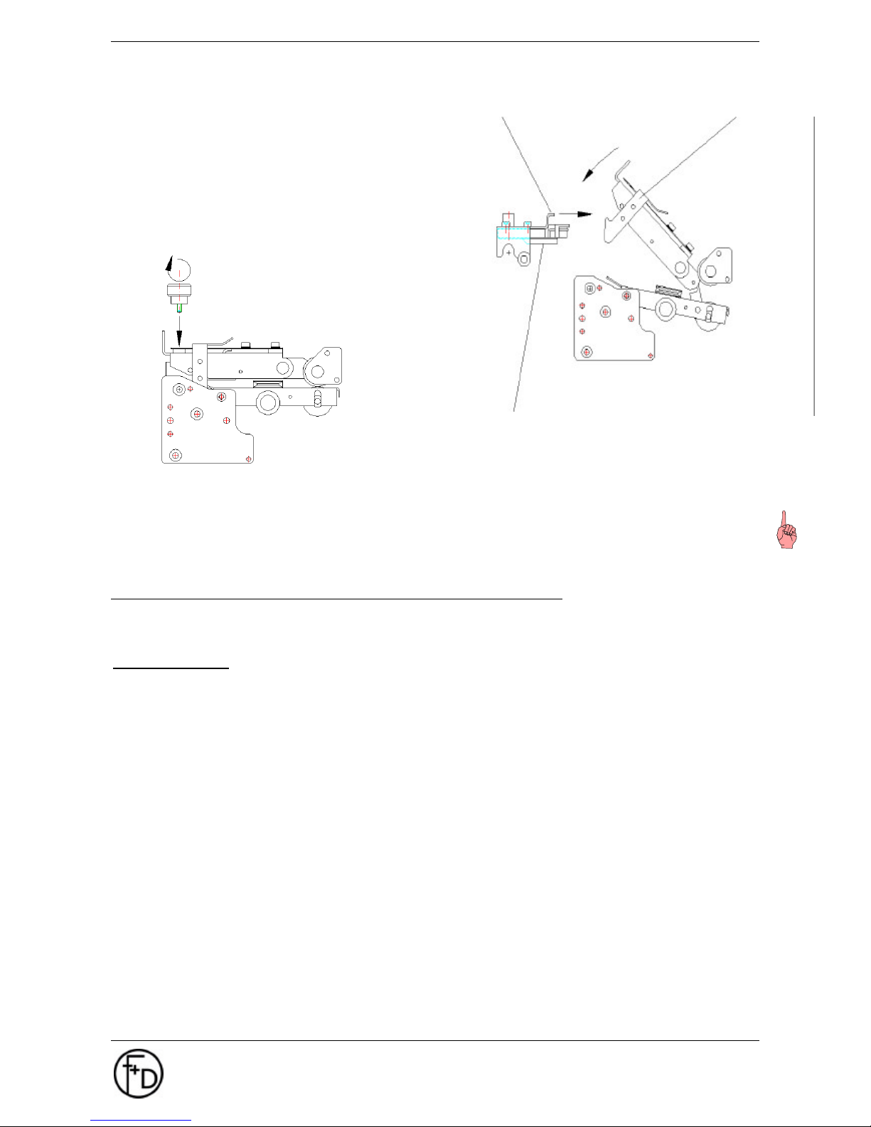
7. Nest the thermal print head from the lower
side into the rectangular holes on the printer
upper via the tabs.
8. Rotate the print head to the upper side until
the thread bush mates with the knurled screw.
9. In order to tighten the knurled screw, draw
down the printer upper and lock.
Notice: Unfortunalety it is not possible to claim for warranty, as the lifetime of the thermal print head is
depending very much, on the boundary conditions (such as paper quality, printing speed, heating time,
quality of thermal ribbon, ...).
4.5 Update of printer software ECO 200
A new printer software / firmware can be load via the serial or parallel port to the ECO 200. Please take note
that an update is only possible if the present version is 1.20 or higher.
Running Update
1. Connect the printer via the parallel port to the LPT-port of the PC.
2. While switching on the printer, please press the buttons „Cut“ and „Clear“ to reach the programming
mode.
3. The display will show „PROGRAM UPDATE“
4. Please activate the MS- DOS mode at the PC or use the file „Update.bat“ (position 5 is inapplicable
then).
5. Now the new version can be load to the printer under MS-DOS using the command
copy/b file name lptx
(for example: copy/b ECES2126.upd lpt1 <Enter>)
6. During data transmission the display shows „READ DATA“. (process will take approx. 15 sec.)
7. When data transmission is finished the printer will show „.....READY.....“
8. Please restart the printer
9. Now the new software is available in the printer.
10. For doing a check please press the „status“ button which effects the software version to be shown.
tab
locking of printer upper
thermal print head with print head adapter
Page 24

24 User Manual ECO 200
Hardware Modifications
F+D Feinwerk- und Drucktechnik GmbH
Kirchenstraße 38, D-69239 Neckarsteinach
Tel.: 06229 7000, Fax: 06229 70067
E-Mail: [email protected], Internet: http://www.fuddruck.de
5. Hardware Modifications
5.1 Thermal Direct Printing
The direct printing requires special thermal direct paper, which reacts to temperature due to special pretreatment. This enables the printing without "colour ribbon", but it is sensitive to light, heat, and various
chemicals.
5.2 Transfer Device
A durable printing format is achieved by means of using wax- or resin-coated ribbons, whose colour film is
heated by the thermal print head and thus transferred onto the label material. The transfer device consists of
a retarding winding device and a motor driven rewinding device.
5.3 Carrier Foil Rewinding Device
Self-adhesive labels of paper, plastic or metal foil are pre-punched on a carrier foil. The smooth resin-like
surface of the label facilitates the removing of the label after the printing process. To rewind the carrier foil
there exists the option carrier foil rewinding device. This device is situated between the printing module and
the roller support.
The carrier foil exits the printing module at the front, is directed around the dispensing roller at the lower end
of the printing module and then put on the carrier foil rewinding device. In case the clamp strap is inserted
into groove and drilled hole, the rewinding device is turned one full circle anti-clockwise and thus the carrier
foil is tensioned. The maximum diameter is 90 mm.
5.4 Front Rewinder
The rewinding of self-adhesive labels without being removed from the carrier foil is possible with a front
rewinder. Its semicircular form guides the label paper fold-free to the rewinding device inside the printer.
When rewinding labels, up to 25 m of standard material can be rewound. In case of rewinding punched
material the tensioner must be rotated backwards.
5.5 Cutting Device
The cutting device separates the label from the rest of the paper stock. It is mounted as an attachment to the
base plate. The connection bush is situated below the printing module in the assembly plate. The position of
the cut is set up in the menu with reference to the synchronization mark. The cutting device can separate
paper up to a weight of 180 g/m2.
Paper particles should be removed as they could lead to malfunctions, when jammed in the rotating knife.
5.6 Dispensing Device
In the case that the printed labels are directly applied to the object, then the dispensing device comes into
action. The carrier foil is guided around the dispensing edge at 90° downwards and tightened via the
dispensing roller and the carrier foil rewinding device. Thus the label is peeled and presented on the
dispensing table. When removed, a sensor signal triggers the printout of the next label.
Page 25

User Manual ECO 200
Hardware Modifications
F+D Feinwerk- und Drucktechnik GmbH
Kirchenstraße 38, D-69239 Neckarsteinach
Tel.: 06229 7000, Fax: 06229 70067
E-Mail: [email protected], Internet: http://www.fuddruck.de
25
5.7 External Rewinder / Winder
The external rewinder is an accessory to the label printer, which rewinds large label rolls after printing. This
unit is connected to the printer by means of an adaptor plate. The external rewinder can be combined with
the external winder, if desired, to ensure that equally large label rolls can be wound and rewound.
Page 26
26 User Manual ECO 200
Service Diagnosis
F+D Feinwerk- und Drucktechnik GmbH
Kirchenstraße 38, D-69239 Neckarsteinach
Tel.: 06229 7000, Fax: 06229 70067
E-Mail: [email protected], Internet: http://www.fuddruck.de
6. Service Diagnosis
6.1 Improvement of the Printing Quality
Unprinted stripes run over the printed image in printing direction
• Dust particles are fixed onto the thermal print head and have to be removed with a spirit dampened
cloth.
• Dot failure due to mechanical influence or electrostatic charging: the thermal print head has to be
changed. See maintenance notice: change thermal print head!
Entire printed image too weak
• Check printing parameter and change if necessary (reduce speed, increase heating time)
• Clean thermal print head with spirit dampened cloth when printer is turned off, do not use hard or sharp-
edged items!
• In transfer printing mode: used paper - transfer ribbon - combination not suitable, apply combination as
preset by manufacturer or determine by tryout.
Inside the printed image small "islands" are not printed
• Dust particles on the paper lift the print head at this point and prevent the printing.
• A damaged printer roller leading to a lack of pressure at this point. The unit must be sent to F+D for
repair (see 2.9).
Printed image too weak on one side
• Thermal print head has to be adjusted anew horizontally.
• Adjust contact pressure spring of thermal print head.
Unprinted stripes run diagonally over the printed image
• Reason is the formation of folds in the transfer ribbon
• Check guidance of thermal ribbon
• Adjust roller with thermal transfer ribbon laterally until ribbon is fold-free
• Remove unwound ribbon and re-insert thermal transfer ribbon
• If thermal transfer ribbon crinkles considerably, the heating time is set too high and thus also leads to
formation of wrinkles; reduce heating time.
• In case winding- and re-winding device are no longer parallel, they have to be adjusted anew.
Page 27
User Manual ECO 200
Service Diagnosis
F+D Feinwerk- und Drucktechnik GmbH
Kirchenstraße 38, D-69239 Neckarsteinach
Tel.: 06229 7000, Fax: 06229 70067
E-Mail: [email protected], Internet: http://www.fuddruck.de
27
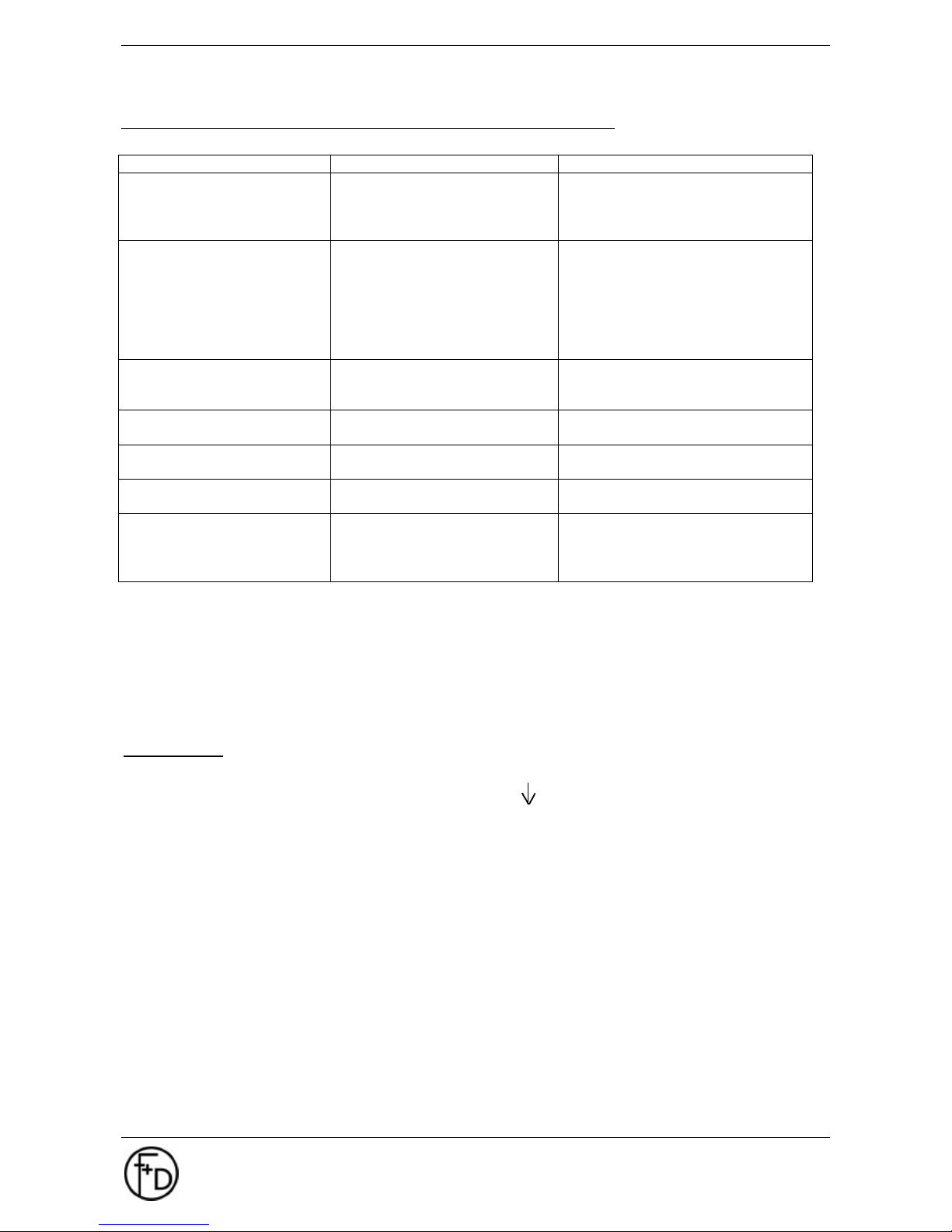
6.2 Error Correction
Error Description Reason for Error Error Correction
No green LED Mains Cable
Mains Plug
Mains Fuse
Internal Power Supply defective
Change Mains Cable
Establish correct contact
Change Mains Fuse
Manufacturer Service
No printed image Print Parameter incorrect
Transfer ribbon inserted
incorrectly
Thermal Paper incorrect
Transfer ribbon of other quality
Adjust print parameter anew
Insert transfer ribbon (according to
drawing)
Use material recommended by
manufacturer
Use transfer ribbon recommended by
manufacturer
Label material is transported
insufficiently (buckled printed
image)
Dirty Transport Rollers Clean transport rollers (see 4.3)
Label material is not
transported at all
Transport rollers are not driven Manufacturer Service
Transfer ribbon is not
transported at all
Transfer ribbon torn Insert transfer ribbon anew and
depress Print-Key
Unauthorized Paper Jam- /
Paper End-Error Message
Paper Sensor set incorrectly
Execute the option Start? in menu
Printer Data/Automat. Paper Sensor
In dispensing mode the label is
retracted before it can be
taken out
Paper Jam Bring label into dispensing position
by using the -key and remove it
(remove Dispensing Table if
necessary )
Every error switches the display from the standard window to the error window, and activates the error-LED.
It is also possible that several errors occur at the same time, for example sequence errors, where the error
with the highest priority is displayed. The priority increases with the increasing error code number.
Inside the status display up to 8 error codes will be displayed in the 2nd status window
(depress status-key 2x).
The error-messages as displayed in the LCD-display are divided into 3 categories:
Error Codes:
01 - 99 - WARNING lowest priority
100 - 239 - ERROR
240 - 255 - HARDWARE highest priority
Page 28
28 User Manual ECO 200
Service Diagnosis
F+D Feinwerk- und Drucktechnik GmbH
Kirchenstraße 38, D-69239 Neckarsteinach
Tel.: 06229 7000, Fax: 06229 70067
E-Mail: [email protected], Internet: http://www.fuddruck.de
6.2.1 Error Level 1
In this error status all printer functions are still allowed. After warning-message(s) have been deleted by
depressing the CLEAR-key, the printout will be started, which can be incorrect. With this error category most
of the time incorrect control sequences or object sequences by the user are the reason. As far as possible,
these are replaced by standard values.
WARNING-messages can always be erased by depressing the CLEAR-key.
Reaction of red LED: blinking slowly
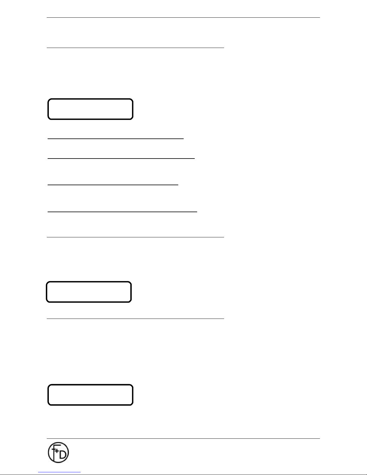
The first display line contains the error category and the error number,
the second display line hints at a possible error source.
Deviating from this standard reaction to warnings further possibilities can be set via the menu:
Menu: PRINTER INFOS / Warnings / confirm
This menu corresponds to the above description. Warnings are deleted by depressing the CLEAR-key.
Menu: PRINTER INFOS / Warnings / display only
Warnings are displayed as usual, but do not have to be confirmed by the user. The printing process will not
be interrupted.
Menu: PRINTER INFOS / Warnings / ignore
Warnings are neither displayed, nor do they have to be confirmed. Via status request and status display they
can be called in.
Menu: PRINTER INFOS / Warnings / √ ignore #70
Warning #70 (character?) will be completely ignored and is preset as a standard in the printer.
6.2.2 Error Level 2
In this status all printer functions are allowed, but it can no longer be printed. This error category most of the
time shows serious label set errors, memory overflows or paper errors. Paper errors can normally be
cleared. Other errors require in the main a switching off and on of the printer.
ERROR-messages cannot be deleted via CLEAR-key.
Reaction of the red LED: blinking quickly
The first display line contains the error category and the error number,
the second display line hints at a possible error source.
6.2.3 Error Level 3
In this status all printer functions are allowed, but it can no longer be printed. This error category concerns
either an incorrect printer configuration or a hardware error.
An incorrect printer configuration means for example a logged-on cutting device, although no cutting device
is connected. If this is triggered, a hardware error message is the result. Hardware errors due to incorrect
printer configuration can be resolved by the user. This is not the case with pure hardware errors. Here, the
user has to contact the Service Department.
HARDWARE-messages cannot be deleted via CLEAR-key.
Reaction of the red LED: blinking constantly
The first display line contains the error category and the error number,
the second display line hints at a possible error source.
HARDWARE #240
cutter
WARNING #023
control sequence
ERROR #185
insert memory
Page 29
User Manual ECO 200
Accessories, Options
F+D Feinwerk- und Drucktechnik GmbH
Kirchenstraße 38, D-69239 Neckarsteinach
Tel.: 06229 7000, Fax: 06229 70067
E-Mail: [email protected], Internet: http://www.fuddruck.de
29
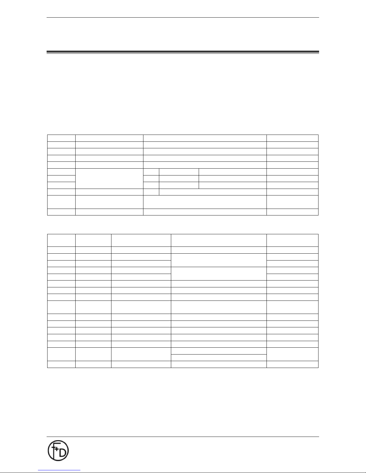
7. Accessories, Options
F+D Order Form Fax : +49(0)6229-70067
Customer: ..............................................................
Name: ..............................................................
Tel.: ..............................................................
Printer: ..............................................................
Spare part:
Amount Description Remarks Article-No.
Cutting Device complete 3073.01.735.30.40
Dispenser complete 3073.01.835.30.40
Rewinding Device with fixing screws 3073.01.889.90.40
Thermal Print head with pre-assembled adaptor 3073.01.763.90.40
2 m DB9 - DB9 3073.01.921.40.40
2 m DB9 - DB25 3073.01.922.40.40
Serial Cable
... m DB9 - DB ... according to customer 3073.01.914.40.40
Parallel Cable 2 m Centronics 9120.11.303.20.00
Labelling SoftwareSprintLabel
Labelling Software for Win 95, 98, NT 4.0
Foils and Papers: Recommended by F+D
Amount Size
width/long
Transfer Ribbon Remarks Article-No.
100 x 200m F13, black Resin (max 100mm/s)
110 x 450m F40, black 3070.99.801.90.89
60 x 450m F41, black
Resin/Wax (max 250mm/s)
3070.99.802.90.89
110 x 400m F42, black 3070.99.803.90.89
60 x 400m F43, black
Wax (max 300mm/s)
3070.99.804.90.89
Thermal Label
100 x 60 THE Top-D 1200/R Standard (max 100mm/s)
100 x 60 THE Top-U 1200/R Highspeed (max 300mm/s)
Thermal Paper -
endless
110 x 250m TP F9 Standard (max 100mm/s)
Thermal Transfer
100 x 60 Gloss 1500/R with F40/F41/F42/F43 3070.04.506.40.89
75 x 46 Gloss with F40/F41/F42/F43
75 x 46 Alu with F13
with F40/F41/F42/F43Transfer-white
with F40/F41/F42/F43
Page 30

30 User Manual ECO 200
Technical Data
F+D Feinwerk- und Drucktechnik GmbH
Kirchenstraße 38, D-69239 Neckarsteinach
Tel.: 06229 7000, Fax: 06229 70067
E-Mail: [email protected], Internet: http://www.fuddruck.de
8. Technical Data
Printing Method: Thermal Direct- or Thermal Transfer Printing
Print Resolution: 8 dots/mm
Printing Speed: 200 mm/sec
Print Width: 108 mm
History Control: Software
Fonts: 2 internal bitmap fonts: Courier bold, Arial bold; optional: bitmap fonts
loadable
Font Sizes: Width and Height 2 - 6 mm, Courier: 6/8/10/12/14
Arial: 6/8/9/10/12/14/16/18/20/22 as well as by steps up to 255
Barcodes: Code 2 of 5 Interleaved, Code 39, Code 128, EAN 8, EAN 13, EAN 128,
PDF 417A, Barcodes variable in height, module width, and ratio.
Optionally with control line, check digit, subscript line, and start-/stop-code
Drawing Capability: line, box with varying line widths
Specialities: 2-level-technology for fixed and variable objects (text, barcode, logo). All
objects can be copied into the image memory in transparent / non
transparent mode. Text- as well as barcode-objects can be placed precisely
and indexed numerically
Processor: Intel 32 bit
RAM: 8 MB
Interfaces: Parallel IEEE 1284 (ECP) , RS 232S 4800 - 38,400 baud
Operation Panel: 6 operation keys, 2 x 16 digit LCD, 2 LED's
Labelling Material *: Thermal paper, standard paper, plastic foils, self- adhesive and cardboard
labels, label height 10 - 500 mm Label width 30 - 110 mm, paper guide way
centred to the thermal print head, outer diameter 140 mm max., core
diameter 12, 40, and 50 mm
Transfer Ribbon *: Length max. 450 m, width max. 110 mm, roll diameter max. 75 mm, core
diameter 25.4 mm
Label Reverse: Yes
Monitoring: Paper- and ribbon-end, synchronization: "scan-through" optical sensoring
Measurements: H x W x D in mm 275 x 250 x 351
Weight: 9 kg
Electrical: 230/115 V (auto-switch), 50/60 Hz, Current 1.1/2.2 A, fuse T 3.15 A,
Environmental Conditions: 10 - 45°C, 20 - 80% humidity (non condensing)
Options: Label dispenser, cutting device, RFID Device, internal and external rewinder
Driver: WindowsTM 95, 98, NT 4.0, 2000 und XP
Software: Labelling Software SprintLabel
*F+D also supplies custom tailored consumables such as thermal papers, labels, and transfer ribbons
Page 31
User Manual ECO 200
Declaration of Conformity
F+D Feinwerk- und Drucktechnik GmbH
Kirchenstraße 38, D-69239 Neckarsteinach
Tel.: 06229 7000, Fax: 06229 70067
E-Mail: [email protected], Internet: http://www.fuddruck.de
31
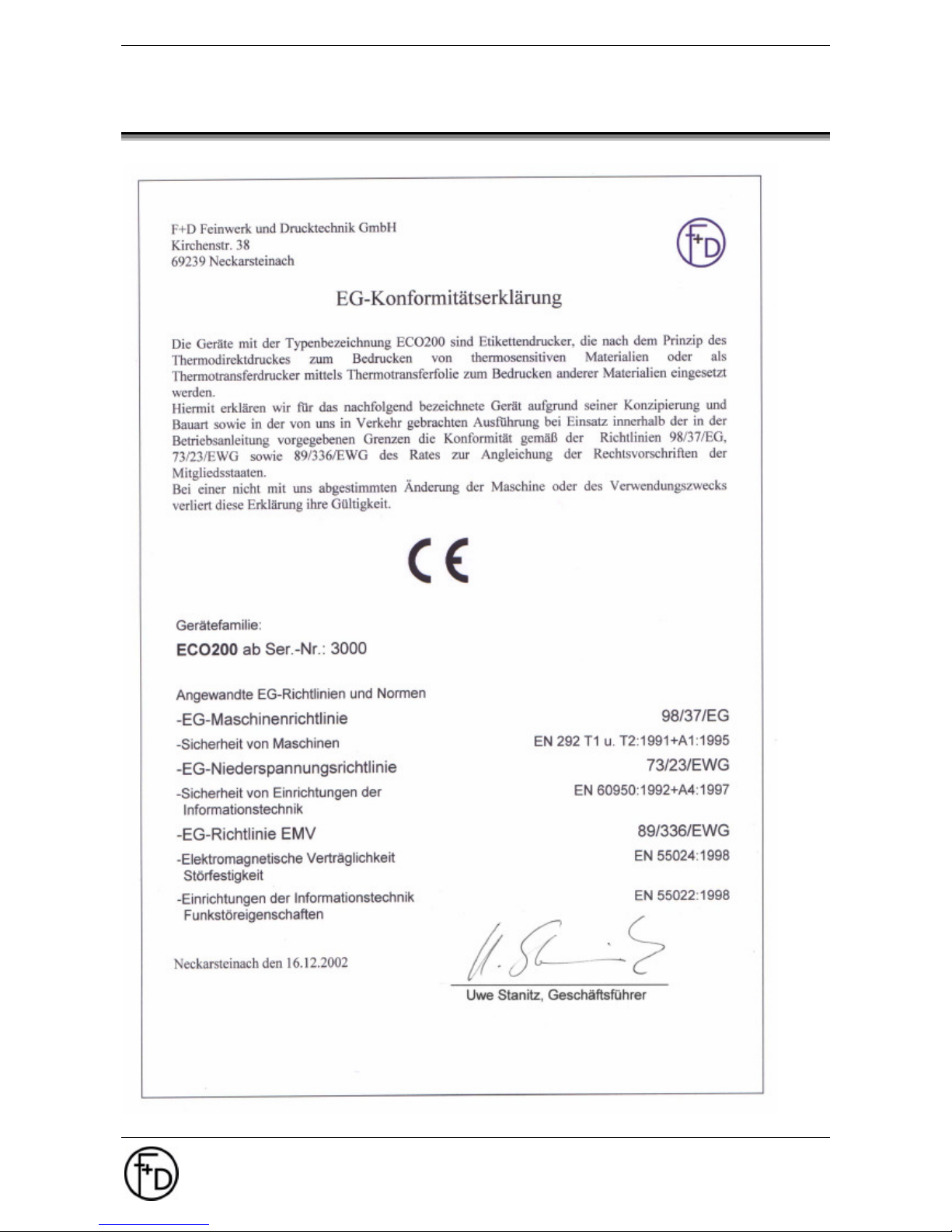
9. Declaration of Conformity
Page 32

32 User Manual ECO 200
Index
F+D Feinwerk- und Drucktechnik GmbH
Kirchenstraße 38, D-69239 Neckarsteinach
Tel.: 06229 7000, Fax: 06229 70067
E-Mail: [email protected], Internet: http://www.fuddruck.de
10. Index
Carrier Foil Rewinding Device...........................24
Changing of Thermal Print Head.......................22
Character / LCD................................................ 21
Cleaning of the Feed Rollers .............................22
Cleaning of the Thermal Print Head .................. 22
Control Panel...................................................... 9
Copies..............................................................16
Cutting Device............................................20, 24
Cutting Position ................................................17
Dispensing........................................................ 19
Dispensing Device............................................24
Dispensing Position..........................................17
Error Correction................................................27
External Rewinder / Winder ..............................25
Front Rewinder.................................................24
Hardware Modifications.....................................24
Heating Time TPH............................................ 18
Image Abort ......................................................16
Image Height....................................................16
Image Width.....................................................16
Improvement of the Printing Quality ..................26
Insertion of Paper ...............................................6
Keys................................................................. 10
Label Data........................................................16
Main Menu Mode..............................................11
Mains Switch ......................................................5
Maintenance..................................................... 22
Makro Navigater ...............................................15
Menu and Parameters.......................................13
Operating............................................................9
Paper End ........................................................ 16
Paper Jam........................................................16
Paper Sensor.................................................... 19
Parallel Interface.................................................7
Print - Status.....................................................14
Print Parameters ...............................................18
Printer - Mode...................................................19
Printer Specs....................................................19
Printing speed................................................... 18
Print-out stored label set................................... 14
RS232 ..............................................................20
Serial Interface ...................................................8
Service Diagnosis.............................................26
Sub-Menu Mode............................................... 11
Synchronization................................................18
Technical Data..................................................30
Thermal Direct Printing .....................................24
TOF-Offset ....................................................... 17
Transfer............................................................20
Transfer Device ................................................24
Update Logos and Fonts...................................21
Update of printer software................................. 23
Page 33

F+D Feinwerk- und Drucktechnik GmbH
Kirchenstr. 38
D-69239 Neckarsteinach
Copyright by F+D 3073.02.994.90.06
Spezifications subject to change without prior notice
 Loading...