

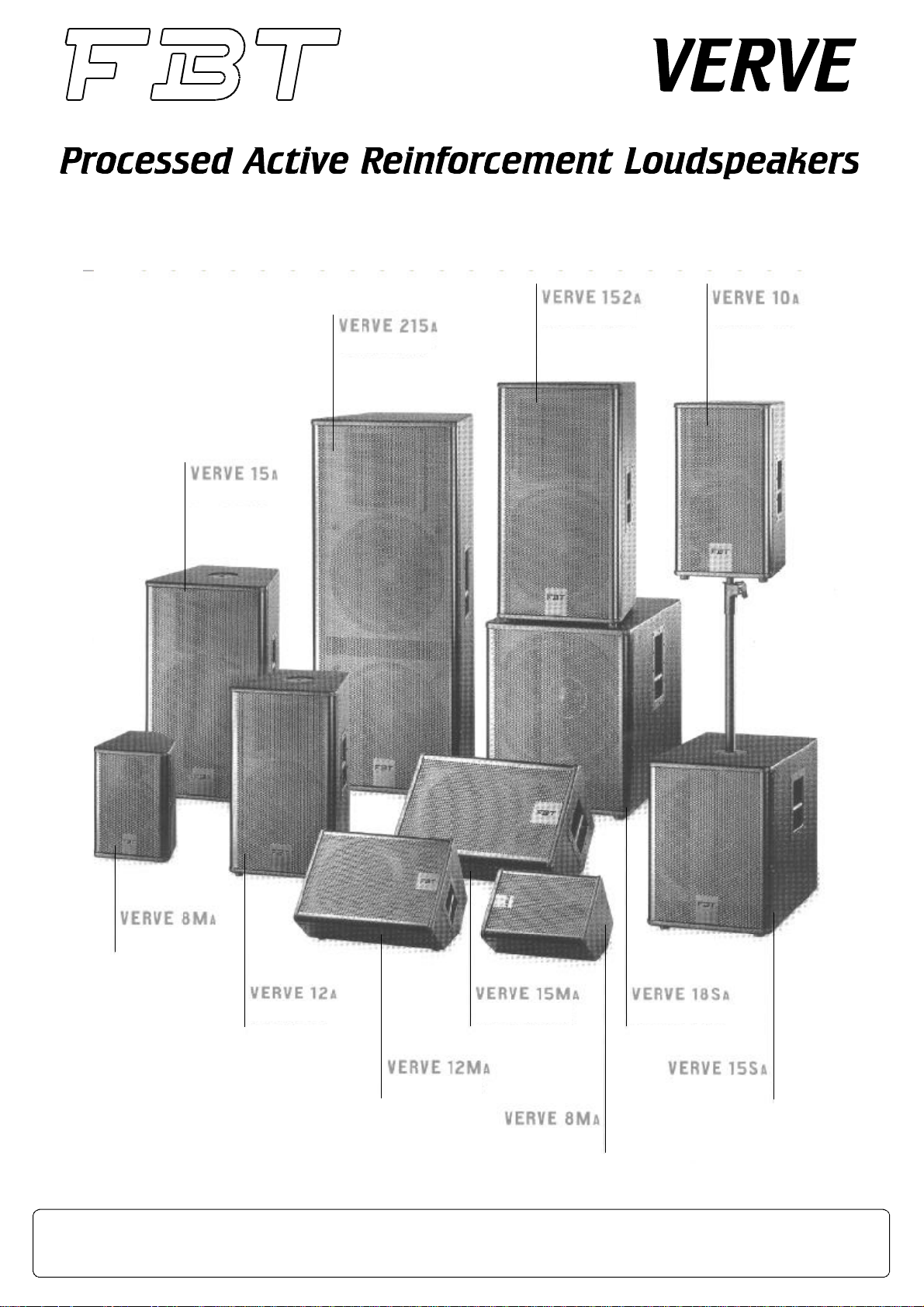
Page 1
FBTELETTRONICAS.p.A.-ZONAIND.LESQUARTABUE-62019RECANATI(MC)-ITALY
tel.071750591r.a.-fax0717505920-e-mail:info@fbt.it-www.fbt.it
Page 2

Page 3

INDICE
INDEX
INDEX
INHALTSVERZEICHNIS
IMPORTANTIISTRUZIONIDISICUREZZA...........................................................................................................................
CARATTERISTICHEGENERALI...........................................................................................................................................
INSTALLAZIONE....................................................................................................................................................................
CONNESSIONI.......................................................................................................................................................................
PANNELLOCONNESSIONI................................................................................................................................................
ALIMENTAZIONE...................................................................................................................................................................
DIAGRAMMI.......................................................................................................................................................
LAYOUT............................................................................................................................................................................
SPECIFICHETECNICHE.....................................................................................................................................................
ACCESSORI...............................................................................................................................................................
IMPORTANTSAFETYINSTRUCTIONS................................................................................................................................
GENERALFEATURES...........................................................................................................................................................
INSTALLATION.......................................................................................................................................................................
CONNECTIONS.....................................................................................................................................................................
CONNECTIONPANEL........................................................................................................................................................
POWERSUPPLY...................................................................................................................................................................
DIAGRAMS........................................................................................................................................................
LAYOUT...........................................................................................................................................................................
TECHNICALSPECIFICATIONS...........................................................................................................................................
ACCESSORIES..........................................................................................................................................................
9/10/11/12/13
9/10/11/12/13
6/7
14/15
18/19/20
6/7
14/15
18/19/20
1
3
4
5
8
16
1
3
4
5
8
16
INFORMATIONSDESÉCURITÉIMPORTANTES................................................................................................................
CARACTÉRISTIQUESGÉNÉRALES...................................................................................................................................
INSTALLATION......................................................................................................................................................................
BRANCHEMENTS.................................................................................................................................................................
PANNEAUCONNEXIONS.................................................................................................................................................
ALIMENTATION.....................................................................................................................................................................
DIAGRAMS........................................................................................................................................................
LAYOUT............................................................................................................................................................................
CARACTÉRISTIQUESTECHNIQUES................................................................................................................................
ACCESSOIRES..........................................................................................................................................................
WICHTIGESICHERHEITSHINWEISE..................................................................................................................................
ALLGEMEINEMERKMALE...................................................................................................................................................
INSTALLATION......................................................................................................................................................................
ANSCHLÜSSE.......................................................................................................................................................................
BUCHSENFELD.................................................................................................................................................................
VERSORGUNG.....................................................................................................................................................................
DIAGRAMME.....................................................................................................................................................
LAYOUT...........................................................................................................................................................................
TECHNISCHEDATEN.........................................................................................................................................................
ZUBEHÖR..................................................................................................................................................................
9/10/11/12/13
14/15
18/19/20
9/10/11/12/13
14/15
18/19/20
2
3
4
5
6/7
8
17
2
3
4
5
6/7
8
17
Page 4
1
WARNING
ATTENZIONE
WARNING
ATTENZIONE
RISCHIODISHOCKELETTRICO
NONAPRIRE
PEREVITAREILRISCHIODISHOCKELETTRICO
PEREVITAREILRISCHIODISHOCKELETTRICO
NONUSAREUTENSILIMECCANICIALL'INTERNO
NONUSAREUTENSILIMECCANICIALL'INTERNO
CONTATTAREUNCENTRODIASSISTENZAQUALIFICATO
CONTATTAREUNCENTRODIASSISTENZAQUALIFICATO
PEREVITAREILRISCHIODIINCENDIOODISHOCKELETTRICO
PEREVITAREILRISCHIODIINCENDIOODISHOCKELETTRICO
NONESPORREL'APPARECCHIATURAALLAPIOGGIA
NONESPORREL'APPARECCHIATURAALLAPIOGGIA
!
!
NONAPRIREILCOPERCHIO
NONAPRIREILCOPERCHIO
OALL'UMIDITA'
OALL'UMIDITA'
QUESTOSIMBOLOAVVERTE,LADDOVEAPPARE,LAPRESENZADIUNA
QUESTOSIMBOLOAVVERTE,LADDOVEAPPARE,LAPRESENZADIUNA
TENSIONEPERICOLOSANONISOLATAALL’INTERNODELLACASSA:
TENSIONEPERICOLOSANONISOLATAALL’INTERNODELLACASSA:
ILVOLTAGGIOPUÒESSERESUFFICIENTEPERCOSTITUIRE
ILVOLTAGGIOPUÒESSERESUFFICIENTEPERCOSTITUIRE
ILRISCHIODISCOSSAELETTRICA.
ILRISCHIODISCOSSAELETTRICA.
QUESTOSIMBOLOAVVERTE,LADDOVEAPPARE,DELLA
QUESTOSIMBOLOAVVERTE,LADDOVEAPPARE,DELLA
PRESENZADIIMPORTANTIISTRUZIONIPERL’USOEPER
PRESENZADIIMPORTANTIISTRUZIONIPERL’USOEPER
LAMANUTENZIONENELLADOCUMENTAZIONE
LAMANUTENZIONENELLADOCUMENTAZIONE
ALLEGATA.SIPREGADICONSULTAREILMANUALE.
ALLEGATA.SIPREGADICONSULTAREILMANUALE.
!
!
RISKOFELECTRICSHOCK
DONOTOPEN
TOREDUCETHERISKOFELECTRICSHOCK
DONOTREMOVECOVER.NOUSERSERVICEABLE
PARTSINSIDE.REFERSERVICINGTOQUALIFIED
TOPREVENTFIREORELECTRICSHOCKDONOT
EXPOSETHISEQUIPMENTTORAINORMOISTURE
WHEREMARKED,THISSYMBOLINDICATESADANGEROUSNON-
WHEREMARKED,THISSYMBOLINDICATESADANGEROUSNONISOLATEDVOLTAGEINSIDETHELOUDSPEAKER:
ISOLATEDVOLTAGEINSIDETHELOUDSPEAKER:
SUCHVOLTAGECOULDBESUFFICIENTTORESULTINTHERISKOF
SUCHVOLTAGECOULDBESUFFICIENTTORESULTINTHERISKOF
ELECTRICSHOCK.
ELECTRICSHOCK.
WHEREMARKED,THISSYMBOLINDICATESIMPORTANT
WHEREMARKED,THISSYMBOLINDICATESIMPORTANT
USAGEANDMAINTENANCEINSTRUCTIONSINTHE
USAGEANDMAINTENANCEINSTRUCTIONSINTHE
ENCLOSEDDOCUMENTS.PLEASEREFERTOTHE
ENCLOSEDDOCUMENTS.PLEASEREFERTOTHE
!
!
MANUAL.
MANUAL.
SERVICEPERSONNEL
!
!
IMPORTANTIISTRUZIONIDISICUREZZA
IMPORTANTIISTRUZIONIDISICUREZZA
1)Leggerequesteistruzioni
1)Leggerequesteistruzioni
2)Conservarequesteistruzioni
2)Conservarequesteistruzioni
3)Fareattenzioneatuttigliavvertimenti
3)Fareattenzioneatuttigliavvertimenti
4)Seguiretutteleistruzioni
4)Seguiretutteleistruzioni
5)Nonusarequestodispositivovicinoall’acqua
5)Nonusarequestodispositivovicinoall’acqua
6)Puliresoloconunostrofinaccioasciutto
6)Puliresoloconunostrofinaccioasciutto
7)Nonostruireleaperturediventilazione.L’installazionedeveessere
7)Nonostruireleaperturediventilazione.L’installazionedeveessere
eseguitainbasealleistruzionifornitedalproduttore.
eseguitainbasealleistruzionifornitedalproduttore.
8)Noninstallarenellevicinanzedifontidicalorecometermosifoni,
8)Noninstallarenellevicinanzedifontidicalorecometermosifoni,
valvolediregolazione,stufeoaltriapparecchi(amplificatoricompresi)
valvolediregolazione,stufeoaltriapparecchi(amplificatoricompresi)
cheproduconocalore
cheproduconocalore
9)Nonannullarel’obiettivodisicurezzadellespinepolarizzateocon
9)Nonannullarel’obiettivodisicurezzadellespinepolarizzateocon
messaaterra.Lespinepolarizzatehannoduelame,unapiùlarga
messaaterra.Lespinepolarizzatehannoduelame,unapiùlarga
dell’altra.Unaspinaconmessaaterrahaduelameeunterzopolodi
dell’altra.Unaspinaconmessaaterrahaduelameeunterzopolodi
terra.Lalamalargaoilterzopoloservonoperlasicurezza
terra.Lalamalargaoilterzopoloservonoperlasicurezza
dell’utilizzatore.Selaspinafornitanonèadattaallapropriapresa,
dell’utilizzatore.Selaspinafornitanonèadattaallapropriapresa,
consultareunelettricistaperlasostituzionedellaspina.
consultareunelettricistaperlasostituzionedellaspina.
10)Proteggereilcavodialimentazionedalcalpestioedalla
10)Proteggereilcavodialimentazionedalcalpestioedalla
compressione,inparticolareincorrispondenzadispine,prolunghee
compressione,inparticolareincorrispondenzadispine,prolunghee
nelpuntodalqualeesconodall’unità.
nelpuntodalqualeesconodall’unità.
11)Usaresolodispositiviopzionali/accessorispecificatidalproduttore.
11)Usaresolodispositiviopzionali/accessorispecificatidalproduttore.
12)Utilizzareesclusivamenteconcarrelli,supporti,
12)Utilizzareesclusivamenteconcarrelli,supporti,
treppiedi,mensoleotavolespecificatidalproduttoreo
treppiedi,mensoleotavolespecificatidalproduttoreo
vendutiunitamenteall’apparecchio.Sesiutilizzaun
vendutiunitamenteall’apparecchio.Sesiutilizzaun
carrelloprestareattenzionedurantelospostamento
carrelloprestareattenzionedurantelospostamento
combinatodelcarrelloedell’apparecchio,perevitareil
combinatodelcarrelloedell’apparecchio,perevitareil
verificarsididannidovutiadeventualeribaltamento.
verificarsididannidovutiadeventualeribaltamento.
13)Staccarelaspinaincasoditemporaleoquandononsiusa
13)Staccarelaspinaincasoditemporaleoquandononsiusa
l’apparecchioperunlungoperiodo.
l’apparecchioperunlungoperiodo.
14)Perl’assistenzatecnicarivolgersiapersonalequalificato.
14)Perl’assistenzatecnicarivolgersiapersonalequalificato.
L’assistenzatecnicaènecessarianelcasoincuil’unitàsia
L’assistenzatecnicaènecessarianelcasoincuil’unitàsia
danneggiata,peres.perproblemidelcavodialimentazioneodella
danneggiata,peres.perproblemidelcavodialimentazioneodella
spina,rovesciamentodiliquidiodoggetticadutiall’interno
spina,rovesciamentodiliquidiodoggetticadutiall’interno
dell’apparecchio,esposizioneallapioggiaoall’umidità,anomaliedi
dell’apparecchio,esposizioneallapioggiaoall’umidità,anomaliedi
funzionamentoocadutedell’apparecchio.
funzionamentoocadutedell’apparecchio.
IMPORTANTSAFETYINSTRUCTIONS
IMPORTANTSAFETYINSTRUCTIONS
1)Readtheseinstructions
1)Readtheseinstructions
2)Keeptheseinstructions
2)Keeptheseinstructions
3)Heedallwarnings
3)Heedallwarnings
4)Followallinstructions
4)Followallinstructions
5)Donotusethisapparatusnearwater
5)Donotusethisapparatusnearwater
6)Cleanonlywithdrycloth
6)Cleanonlywithdrycloth
7)Donotblockanyventilationopenings.Installinaccordancewiththe
7)Donotblockanyventilationopenings.Installinaccordancewiththe
manufacturer’sinstructions.
manufacturer’sinstructions.
8)Donotinstallnearanyheatsources,suchasradiators,heat
8)Donotinstallnearanyheatsources,suchasradiators,heat
registers,stovesorotherapparatus(includingamplifiers)thatproduce
registers,stovesorotherapparatus(includingamplifiers)thatproduce
heat
heat
9)Donotdefeatthesafetypurposeofthepolarizedorgrounding-type
9)Donotdefeatthesafetypurposeofthepolarizedorgrounding-type
plug.Apolarizedplughastwobladeswithonewiderthantheother.A
plug.Apolarizedplughastwobladeswithonewiderthantheother.A
groundingtypeplughastwobladesandathirdgroundingprong.The
groundingtypeplughastwobladesandathirdgroundingprong.The
widebladeorthethirdprongareprovidedforyoursafety.Ifthe
widebladeorthethirdprongareprovidedforyoursafety.Ifthe
providedplugdoesnotfitintoyouroutlet,consultanelectricianfor
providedplugdoesnotfitintoyouroutlet,consultanelectricianfor
replacementoftheobsoleteoutlet.
replacementoftheobsoleteoutlet.
10)Protectthepowercordfrombeingwalkedonorpinchedparticularly
10)Protectthepowercordfrombeingwalkedonorpinchedparticularly
at plugs,conveniencereceptacles,andthepointwheretheyexitfrom
at plugs,conveniencereceptacles,andthepointwheretheyexitfrom
theapparatus.
theapparatus.
11)Onlyuseattachments/accessoriesspecifiedbythemanufacturer.
11)Onlyuseattachments/accessoriesspecifiedbythemanufacturer.
12)Useonlywiththecart,stand,tripod,bracket,or
12)Useonlywiththecart,stand,tripod,bracket,or
tablespecifiedbythemanufacturerorsoldwiththe
tablespecifiedbythemanufacturerorsoldwiththe
apparatus.Whenacartisused,usecautionwhen
apparatus.Whenacartisused,usecautionwhen
movingthecart/apparatuscombinationtoavoidinjury
movingthecart/apparatuscombinationtoavoidinjury
fromtip-over.
fromtip-over.
13)Unplugthisapparatusduringlightningstormsor
13)Unplugthisapparatusduringlightningstormsor
whenunusedforlongperiodsoftime.
whenunusedforlongperiodsoftime.
14)Referallservicingtoqualifiedservicepersonnel.
14)Referallservicingtoqualifiedservicepersonnel.
Servicingisrequiredwhentheapparatushasbeendamagedinany
Servicingisrequiredwhentheapparatushasbeendamagedinany
way,suchaspower-supplycordorplugisdamaged,liquidhasbeen
way,suchaspower-supplycordorplugisdamaged,liquidhasbeen
spilledorobjectshavefallenintotheapparatus,theapparatushas
spilledorobjectshavefallenintotheapparatus,theapparatushas
beenexposedtorainormoisture,doesnotoperatenormally,orhas
beenexposedtorainormoisture,doesnotoperatenormally,orhas
beendropped.
beendropped.
L’APPARECCHIODEVEESSERECOLLEGATOALLARETE
ELETTRICAMEDIANTEUNAPRESACONUNCOLLEGAMENTO
ALLATERRADIPROTEZIONE.
Questoapparecchioèdotatodipresadialimentazione;installare
Questoapparecchioèdotatodipresadialimentazione;installare
l’apparatoinmanierachelapresadelcavodialimentazionerisulti
l’apparatoinmanierachelapresadelcavodialimentazionerisulti
facilmenteaccessibile.
facilmenteaccessibile.
PRECAUZIONI
PRECAUZIONI
°Perconsentireunaventilazionesufficienteènecessariopredisporre
°Perconsentireunaventilazionesufficienteènecessariopredisporre
unadistanzaminimadicirca30cm.pertuttiilatidell’apparecchiio.
unadistanzaminimadicirca30cm.pertuttiilatidell’apparecchiio.
°Laventilazionenondovrebbeessereimpeditacoprendoleaperture
°Laventilazionenondovrebbeessereimpeditacoprendoleaperture
diventilazioneconoggettiqualigiornali,tovaglie,tende,ecc.
diventilazioneconoggettiqualigiornali,tovaglie,tende,ecc.
°Nessunasorgentedifiammanuda,qualicandeleaccese,dovrebbe
°Nessunasorgentedifiammanuda,qualicandeleaccese,dovrebbe
esserepostasull’apparecchio.
esserepostasull’apparecchio.
°L’apparecchionondeveessereespostoastillicidiooaspruzzi
°L’apparecchionondeveessereespostoastillicidiooaspruzzi
d’acquaequindisopraaldispositivonondevonoesserepostioggetti
d’acquaequindisopraaldispositivonondevonoesserepostioggetti
contenentiliquidi,comeades.vasi.
contenentiliquidi,comeades.vasi.
°E:Perevitarsidiferirsiquestoapparecchiodeveessere
ATTENZION
°E:Perevitarsidiferirsiquestoapparecchiodeveessere
ATTENZION
assicuratoallaparetesecondoleistruzionidiinstallazioneallegate.
assicuratoallaparetesecondoleistruzionidiinstallazioneallegate.
THEDEVICEMUSTBECONNECTEDTOTHEMAINSTHROUGHA
POWEROUTLETWITHAPROTECTIVEEARTHCONNECTION.
Thisdevicefeaturesapoweroutlet;installthedevicesothattheoutlet
forthepowercordisaccessible.easily
PRECAUTIONS
PRECAUTIONS
°Forproperairventilationpleasemakesuretoleavesufficient
°Forproperairventilationpleasemakesuretoleavesufficient
clearance(min11inc.)onallsidesofthedevice.
clearance(min11inc.)onallsidesofthedevice.
°Pleasedonotcovertheventilationslotswithpapers,tablecloths,
°Pleasedonotcovertheventilationslotswithpapers,tablecloths,
curtains,etc.inordernottopreventventilationofthedevice.
curtains,etc.inordernottopreventventilationofthedevice.
°Pleasedonotplaceanynakedflamesource,suchaslighted
°Pleasedonotplaceanynakedflamesource,suchaslighted
candles,onthedevice.
candles,onthedevice.
°Pleasekeepthedeviceawayfromwaterspringsandsplashesand
°Pleasekeepthedeviceawayfromwaterspringsandsplashesand
pleasedonotplaceanyobjectscontainingliquids,suchasvases,on
pleasedonotplaceanyobjectscontainingliquids,suchasvases,on
thedevice.
thedevice.
°:Toavoidtheriskofinjuriespleasesecurethedeviceto
CAUTION
°:Toavoidtheriskofinjuriespleasesecurethedeviceto
CAUTION
thewallfollowingtheenclosedinstructions.
thewallfollowingtheenclosedinstructions.
Page 5
2
RISQUEDECHOCÉLECTRIQUE
NEPASOUVRIR
STROMSCHLAGGEFAHR
NICHTÖFFNEN
POURÉVITERLERISQUEDECHOCÉLECTRIQUE
NEPASUTILISERD’OUTILSMÉCANIQUESÀL’INTÉRIEUR
CONTACTERUNCENTRED’ASSISTANCEQUALIFIÉ
POURÉVITERLERISQUED’INCENDIEOUDECHOCÉLECTRIQUE
NEPASEXPOSERL’APPAREILLAGEÀLAPLUIEOUÀL’HUMIDIT
!
NEPASOUVRIRLECOUVERCLE
CESYMBOLEPRÉVIENT,LÀOÙILAPPARAÎT,DELAPRÉSENCED'UNE
TENSIONDANGEREUSENONISOLÉEÀL'INTÉRIEURDELACAISSE:
LEVOLTAGEPEUTÊTRESUFFISANTPOURREPRÉSENTER
UNRISQUEDEDÉCHARGESÉLECTRIQUES.
CESYMBOLEPRÉVIENT,LÀOÙILAPPARAÎT,DELAPRÉSENCE
D'IMPORTANTESNOTICESDEMODED'EMPLOIETCONCERNANT
L'ENTRETIENDANSLADOCUMENTATIONJOINTE.VEUILLEZ
CONSULTERLEMODED'EMPLOI.
INFORMATIONSDESÉCURITÉIMPORTANTES
1)Lisezcesinstructions
2)Conservezcesinstructions
3)Faitesattentionàtouslesavertissements
4)Suiveztouteslesinstructions
5)N'employezpascedispositifprèsdel'eau
6)Nenettoyezqu'avecuntorchonsec
7)N’obstruezpaslesouverturesdelaventilation.L’installationdoit
êtreeffectuéeselonlesinstructionsfourniesparleproducteur.
8)Nel'installezpasprèsdesourcesdechaleurcommeradiateurs,
appareilsdechauffage,poêlesoud'autresappareils(ycomprisles
amplificateurs)quiproduisentdelachaleur
9)Nesupprimezpaslesdispositifsdesécuritédesfichespolariséesou
avecmiseàlaterre.Lesfichespolariséessontéquipéesdedeux
bornesdelargeurdifférente.Uneficheavecmiseàlaterreadeux
bornesetuntroisièmepôledeterre.Labornepluslargeouletroisième
pôlesontnécessairespourlasécuritédel'utilisateur.Silafichefournie
n'estpasappropriéepourvotreprise,consultezunélectricienpourle
remplacementdelafiche.
10)Protégezlecâbled'alimentationdupiétinementetdela
compression,enparticulieroùl'ontrouvedesfiches,desrallongeset
danslepointoùilssortentdel'appareil.
11)Employezuniquementdesdispositifsenoption/accessoires
indiquésparleproducteur.
12)Aemployeruniquementavecdeschariots,des
supports,destrépieds,desconsolesoudestables
indiquésparleproducteurouvendusavecl'appareil.
Sivousutilisezunchariot,faitesattentionpendantle
déplacementcontemporainduchariotetdel'appareil,
afind'éviterdesdommagesdusaupossible
renversement.
13)Débranchezlaficheencasd'orageoulorsqu'onn'utilisepas
l'appareilpendantunelonguepériode.
14)Pourl'assistancetechnique,adressez-vousaupersonnelqualifié.
L'assistancetechniqueestnécessaireaucasoùl'appareilest
endommagé,parex.àcausedeproblèmesducâbled'alimentationou
delafiche,durenversementdeliquidesoud'objetstombésàl'intérieur
del'appareil,del'expositionàlapluieouàl'humidité,d'anomaliesde
fonctionnementoudechutesdel'appareil.
L’APPAREILDOITÊTRECONNECTÉAURÉSEAUÉLECTRIQUEPAR
UNEPRISEAYANTUNECONNEXIONDEPROTECTIONDETERRE.
Cetappareilestéquipéd’uneprised’alimentation;installezl’appareil
defaçonàcequelapriseducâbled’alimentationsoitfacilement
accessible.
PRÉCAUTIONS
°Afindepermettreuneventilationsuffisanteilfautdisposerune
distancemin.de30cm.environdetouslescôtésdel’appareil.
°Laventilationnedoitpasêtreempêchéeencouvrantlesouvertures
d’aérationavecdesobjetscommejournaux,nappes,rideaux,etc.
°Aucunesourceàflammenue,commeparexempledesbougies
allumées,nedoitêtreposéesurcetappareil.
°L’appareilnedoitpasêtreexposéàlastillationouauxjetsd’eauet
doncilnefautpasposersurledispositifdesobjetscontenantdes
liquides,commeparexempledesvases.
°:Afind’éviterdevousblesser,ilfautquecet appareil
ATTENTION
soitattachéaumurd’aprèslesinstructionsd’installationci-jointes.
STROMSCHLAGGEFAHRNICHTDENDECKELÖFFNEN
WENDENSIESICHANEINENQUALIFIZIERTENKUNDENDIENST
UMRISIKENVONSTROMSCHLAGUNDBRANDAUSZUSCHLIESSEN
SETZENSIEDASGERÄTKEINEMREGENODERFEUCHTIGKEITAUS
DIESESSYMBOLVERWEISTAUFDIEPRÄSENZEINERGEFÄHRLICHEN
NICHTISOLIERTENSPANNUNGINDERLAUTSPRECHERBOX:DIE
SPANNUNGKANNGENÜGENDSTARKSEIN,UMEINE
STROMSCHLAGGEFAHRDARZUSTELLEN.
DIESESSYMBOLVERWEISTAUFWICHTIGEHINWEISEIN
DENMITGELIEFERTENBEDIENUNGS-UND
WARTUNGSANLEITUNGEN.ZIEHENSIEDASHANDBUCH
!
ZURATE.
WICHTIGESICHERHEITSHINWEISE
1)LesenSiedieseAnleitungenaufmerksamdurch.
2)BewahrenSiesiesorgfältigauf.
3)BeachtenSiealleHinweise.
4)HaltenSiesichansämtlicheAnleitungen.
5)VerwendenSiediesesGerätnichtinderNähevonWasser.
6)ReinigenSieesnurmiteinemtrockenenLappen.
7)DieLüftungsöffnungennichtverstellen.DieInstallationmuss
entsprechenddervomHerstellergeliefertenAnleitungerfolgen.
8)VermeidenSiees,dasGerätinderNähevonWärmequellen,wie
Heizkörper,Heizrohre,ÖfenoderanderenwärmeerzeugendenGeräte
(auchVerstärker)aufzustellen.
9)AchtenSiedarauf,dieSicherheitsfunktionderpolarisiertenoder
geerdetenSteckernnichtaufzuheben.PolarisierteSteckerhabenzwei
flacheStifte,einerdavonistbreiteralsderandere.EingeerdeterStecker
hatzweiStifteundeinenErdungsstift.EingeerdeterSteckerhatzwei
KlinkenundeinenErdungsstift.DerbreitereStiftbzw.derdritteStift
dienenIhrerSicherheit.SolltedermitgelieferteSteckernichtinIhre
Steckdosepassen,lassenSieihndurcheinenElektrikerauswechseln.
10)SchützenSiedasStromkabelvorTritt-undDruckeinwirkungen,
insbesondereimBereichderStecker,vonVerlängerungenundbeiihrem
AustrittausdemGerät.
11)VerwendenSieausschließlichvomHerstellerempfohlene
Zusatzgeräte/Zubehörteile.
12)BenutzenSieausschließlichvomHersteller
empfohleneodermitdemGerätverkaufteWagen,
Ständer,Stative,HalterungenoderTische.AchtenSie
beiVerwendungeinesWagensdarauf,dassdasdarauf
stehendeGerätwährendderFahrtnichtumkipptund
Schadenerleidet.
13)SteckenSiedasGerätbeiGewitternoderlängerer
Außerbetriebsetzungbitteab.
14)FürdentechnischenKundendienstwendenSiesichbitte
ausschließlichanqualifiziertesPersonal.Eintechnischer
Kundendiensteinriffwirderforderlich,wenndasGerätaufirgendeine
Weisebeschädigtwird,z.B.durchSchädenamNetzkabeloder-stecker,
durchEintretenvonverschüttetenFlüssigkeitenoderGegenständen,
durchRegenoderFeuchtigkeit,durchHinunterfallen,oderbei
Funktionsstörungen.
DASGERÄTÜBEREINEGEERDETESTECKDOSEANDAS
STROMNETZANSCHLIESSEN.
DiesesGerätistmiteinerSteckdoseausgestattet.InstallierenSiedas
Gerätso,dassdieSteckdosedesStromkabelsleichtzugänglich
resultiert.
VORSICHTSMAßNAHMEN
°HierzumussumalleGeräteseitenherumeineMindestdistanzvon30
cmberücksichtigtwerden.
°
BehindernSiedieVentilationkeinesfallsdurchAbdeckender
LüftungsöffnungenmitZeitungen,Tischtüchern,Vorhängenusw.
°
KeineoffenenFlammen,beispielshalberbrennendeKerzen,aufdas
Gerätstellen.
°
DasGerätistunbedingtvorTropfenoderWasserspritzernzu
schützen.StellenSiealsokeinesfallsFlüssigkeitsbehälter,wie
beispielsweiseBlumenvasendarauf.
°
ACHTUNG:UmVerletzungsgefahrenauszusschließen,mussdieser
ApparatentsprechendderbeigefügtenInstallationsanleirungander
Wandgesichertwerden.
Page 6

CARACTÉRISTIQUESGÉNÉRALES
CARATTERISTICHEGENERALI
GENERALFEATURES
Nuovaseriedidiffusoriprofessionaliinmultistratodibetullaverniciati
antigraffiointeramente“madeinitaly”.
EquipaggiaticonaltoparlantiedriverB&Ccustomdialtissimopregio
garantisconoperformancediassolutorilievonellepiùvastecondizionidi
utilizzo;unariccadotazionedihardwarelarendonoparticolarmenteindicata
ancheperinstallazionifisse.
VERVE8MA]
“compattatuttapotenza”,idealeperqualsiasiimpiegodirinforzosonoro:
dall’installazionepermanentealclub“live”,dallapiccolabandmusicaleall’auditorium
esaleconferenzae,nonultimo,neiprogettidiacusticacommerciale.
VERVE10A]
(SPL)eperlasuastupefacentequalitàacustica.Diffusoreleggero,facileall’usoper
installazionifisseoinapplicazionimusicaliingenere.
VERVE12A]
indirizzatasiaall’installazionepermanentecheadunuso“live”,erogapotenzaeuna
chiaradefinizionedituttelefrequenzeperunusoagammaestesa.
VERVE15A]
dipressionesonoraedun’altatenutadipotenza.Èlasoluzioneidealeperqualsiasi
progettodirinforzosonoroprofessionaleconmassimadirettivitàecoperturatotale
dellazona.
VERVE12MA]
distingueperilprofilobassodimonitordapalco,compattoeadaltaresistenza.Si
adattaaqualsiasiperformanceedèancheutilizzabilecomediffusoreacusticoa
gammaestesaoinabbinamentoadunsub-woofer.
VERVE15MA]
perproduzioni,spettacolieconcertimedio-grandi:èilmonitordapalcopiùpotente
dellaserie;erogaunaelevatapotenzacontinuaedèperfettamentebilanciatosututte
lefrequenzeconun“basso”ricco,un“medio”apertoelargo,un“alto”cristallinoedi
spessore.
VERVE215A]
garantisceottimaestensioneallebassefrequenzeerispostainfrequenzalineare.
Grazieallatrombaruotabile,èpossibilefarearrayorizzontalidi3diffusoricon
coperturatotaledi120gradi.
VERVE152A]
eventilive,capacediraggiungereanchenotevolidistanzeinesterno,garantisce
ottimaestensioneallebassefrequenze.Grazieallatrombaruotabile,èpossibilefare
arrayorizzontalidi3diffusoriconcoperturatotaledi120gradi.
VERVE15SA]Subwooferbass-reflexcaratterizzatodaunpesoedimensioni
compattepuresibendounaottimaestensionefinoa40Hz
VERVE18SA]Subwooferbass-reflexcaratterizzatodaunpesoedimensioni
compattepuresibendounaottimaestensionefinoa35Hz
Cassaasimmetrica,latomonitorconinclinazionea45gradi.Unavera
Cassatrapezoidale,sidistingueperl’altovaloredipressionesonora
Cassatrapezoidaledielevatafinituraqualitativaesonora;anch’essa
Cassatrapezoidale,modelloultra-leggeromaconuneccezionalelivello
Cassaasimmetricaconlatomonitoreinclinazionea45gradi;si
Cassaasimmetricaconlatomonitoreinclinazionea45gradi.Ideale
Progettatapersoundimpegnativiintouringedinstallazionifisse,
Diffusoreadaltapotenzaindicatoperimportantiinstallazionifisseo
ALLGEMEINEMERKMALE
Completely“manufacturedinitaly”theVERVEseriesareFBT’snew
professionalspeakersystems,featuringbirchplywoodenclosureswitha
scratch&scuffresistantpaintfinish.
AllfeaturehighefficiencycustomB&CwoofersandHFdriverstoprovide
exceptionalsoundperformance.VERVEseriesarecomplementedbya
completeseriesofoptionalmountinghardwareforpermanentinstallations.
VERVE8MA]A
accessories.Areal“compactsoundmachine”foravastrangeofapplications:from
permanent,liveormusicclubs,tosmallbandPA,toconferenceorauditoriums,to
commercialinstallations.
VERVE10A
CapableofhighSPLandremarkablesonicquality,VERVE10Aislight,easytoset-up
inpermanentinstallationsorliveevents.
VERVE12A
soundreinforcementcabinetdeliverssmoothanduniformfrequencyresponseovera
widecoveragearea.
VERVE15A
lessweightwithcomparablemodels,yetwithhighpowerhandlingandoutput:itisthe
idealsolutionforanyprofessionalsoundreinforcementprojectwhereconsistent
soundfieldcoverageisrequired.
VERVE12MA]
stand-polemount,flyinghardwareaccessories.Low-shapedesigned,powerful,
compactandheavyduty,VERVE12MAcansuittoeveryperformance.Withamultifunctionalenclosuredesign,forfull-range“frontof house”speakeruseorfor
musiciansstagemonitoring.
VERVE15MA]
showproductionsandextensivetouringconcertsitisthenextstepupinstage
monitoring:VERVE15MAgivesmassivebasskickwithopenmidfrequenciesand
exceptionalvocals.
VERVE215A]Designedfordemandingsoundsfortouringandfixedinstallations,
guaranteesanoptimalextensionofbassfrequenciesandlinearfrequencyresponses.
Thankstoitsrotatablehorn,itispossibletomakeahorizontalarrayof3speakerswith
atotalcoverof120degrees.
VERVE152A]Highpowerspeakerintendedforimportantfixedinstallationsorlive
events,capableofreachingconsiderableoutsidedistances,guaranteesanoptimal
extensionofbassfrequencies.Thankstoitsrotatablehorn,itispossibletomakea
horizontalarrayof3speakerswithatotalcoverof120degrees.
VERVE15SA]Bass-reflexsubwoofercharacterisedbylowweightandcompact
dimensions,despitehavinganoptimalextensionupto40Hz.
VERVE18SA]Bass-reflexsubwoofercharacterisedbylowweightandcompact
dimensions,despitehavinganoptimalextensionupto35Hz.
symmetricalcabinetwith45deg.monitortaper,flyinghardware
]35mmøtop-hatforstand-polemount,flyinghardwareaccessories.
]FeatureslikeVERVE10A.Thisnewpremiumqualityinstallationand
]FeatureslikeVERVE10.VERVE15isanultra-lightenclosurewithmuch
Asymmetricalcabinetwith45deg.monitortaper,35mmøtop-hatfor
Asymmetricalcabinetwith45deg.monitortaper.Formediumtolarge
Nouvelleséried’enceintesprofessionnellesrèaliséesenbouleaumultiplisavec
unrevêtementpeintureanti-rayureentièrement“madeinitaly”.Équipésde
haut-parleursetmoteursB&Ccustomisésdetrèsgrandequalitégarantissent
desprestationsdetréshautniveaudanslesconditionsd’utilisationlesplus
variées.Lespointsd’accrocheintégrésdansl’ébénisterieprocureàlasérie
VERVEuneadaptationtotalepourdesinstallationsfixes.
VERVE8MA]
toutelazonedecouvertureoccasionnantuneabsencedephénomènesde"boucle"
généralementconstatéssurdesenceintes2voiestraditionnelles.
VERVE10A]
pourinstallationmuraleet2poignéesenmétal.Unecohérenceexceptionnelle,un
contrôletotaldeladispersiondanstoutelazonedecouverture,unniveauSPLélevéet
unereproductionsonoreprécisefontdecetteenceinteunmodèleidéalpourdes
installationsfixesoupourdesprestationsLive.
VERVE12A]
pourinstallationmuraleet2poignéesenmétal.Uncontroletotaldeladispersiondans
toutelazonedecouverture,unereproductionsonoreprécisefontdecetteenceinteun
modèleidéalpourdesinstallationsfixesoupourdesprestationsLive.
VERVE15A]
insertsavecétrierpourinstallationmuraleet2poignéesenmétal.Unecohérence
exceptionnelle,uncontrôletotaldeladispersiondanstoutelazonedecouverture,un
niveauSPLélevéetunerepraductionsonoreprécisefontdecetteenceinteunmodèle
idéalpourdesinstallationsfixesoupourdesprestationsLive.
VERVE12MA]
toutelazonedecouvertureoccasionnantuneabsencedephénomènesde"boucle"
généralementconstatéssurdesenceintes2voiestraditionnelles.Peut-etre
égalementutiliséecommeenceintedefaçadepourdelapetitediffusiongraceà
l'intégrationd'unmanchonpourinstallationsurpied.
VERVE15MA]
"nearfield"(retourdescène).Unecohérenceexceptionnelle,uncontroletotaldela
dispersiondanstoutelazonedecouvertureoccasionnantuneabsencede
phénomènesde"boucle"généralementconstatéssurdesenceintes2voies
traditionnelles
VERVE215A]Projetépourreproduiredessonsdehautniveauentournéeoucomme
installationsfixes,ilgarantituneexcellenteextensiondesbassesfréquencesetde
réponseenfréquencelinéaire.Grâceaucônetournantetlestroisdiffuseurs,ilest
possibled'obtenirunediffusionhorizontaleavecunecouverturetotalede120degrés.
VERVE152A]Diffuseurdehautepuissanceadaptéàdesinstallationsfixesdegrande
dimensionetévènementsendirect,efficacemêmeàdelonguesdistancesàciel
ouvert,ilgarantituneextensionoptimaleàdesbassesfréquences.Grâceaucône
tournantetlestroisdiffuseurs,ilestpossibled'obtenirunediffusionhorizontaleavec
unecouverturetotalede120degrés.
VERVE15SA]Subwooferbass-reflex,malgrésonpoidsetsesdimensionsréduites,il
faitmontred'uneextensionoptimalepouvantarriverjusqu'à40Hz.
VERVE18SA]Subwooferbass-reflex,malgrésonpoidsetsesdimensionsréduites,il
faitmontred'uneextensionoptimalepouvantarriverjusqu'à35Hz.
Unecohérenceexceptionnelle,uncontrôletotaldeladispersiondans
Manchonde35mm(1.4")pourinstallationsurpied,insertsavecétrier
Manchonde35mm(1.4")pourinstallationsurpied,insertsavecétrier
Profiltrapézoidal.Manchonde35mm(1.4")pourinstallationsurpied,
Unecohérenceexceptionnelle,uncontroletotaldeladispersiondans
Réponseenfréquencespécialementadaptéepouruneutilisationtype
DieseneueSerievonProfi-Lautsprechern“madeinitaly”mitGehäuseaus
vielschichtigemBirken-SperrholzundkratzfesterLackierungvereinthohe
Leistungenmiteinemkonkurrenzfähigen.HochwertigenB&CCustom
LautsprechernundTreiberngarantiereneineerstklassigePerformanceunter
denunterschiedlichstenEinsatzbedingungen.Dankdesumfassenden
MontagezubehörseignetsiesichauchbesondersfürortsfesteInstallationen.
VERVE8MA]
Lobingphanomenederherkommlichen2Wege-Konfiguration.
VERVE10A]
TransportgriffausMetall.OurchdashervorragendeFrequenz-undAbstrahlverhalten,
denhohenSPLunddieeinwandfreieKlangwiedergabeeignetsichdieser
LautsprecherideaifürortsfesteInstallationenoderLive-Veranstaltungen
VERVE12A]
TransportgriffausMetall.DurchdashervorragendeFrequenz-undAbstrahlverhalten,
denhohenSPLunddieeinwandfreieKlangwiedergabeeignetsichdieser
LautsprecherideaifürortsfesteInstallationenoderLive-Veranstaltungen
VERVE15A]
TransportgriffeausMetall.DurchdashervorragendeFrequenz-und
Abstrahlverhalten.denhohenSPLunddieeinwandfreieKlangwiedergabeeignetsich
dieserLautsprecherideaifürortsfesteInstallationenoderLive-Veranstaltungen.
VERVE12MA]
auchals"front-of-house"SpeakerdurchdasmultifunktionelleGehausedesignunddie
Stativ-Halterung.
VERVE15MA]
KonzerttourneenentwickeltzeichnetsichdieseSeriedurcheinhervorragendes
Frequenz-undAbstrahlverhaltenohneLobingphanomenederherkommlichen2
Wege-Konfigurationaus
VERVE215A]KonzipiertfürausgezeichnetenSoundonTourundbeifesten
InstallationenundgarantierteineoptimaleErweiterungbeidenniedrigenFrequenzen
undAntwortinlinearerFrequenz.DankdesverstellbarenHornskönnenhorizontale
Arraysaus3LautsprechernmiteinerGesamtabdeckungvon120Gradgebildet
werden.
VERVE152A]Hochleistungs-LautsprecherfürbedeutendeFestinstallationenoder
Live-Events,erreichtauchimFreienbeachtlicheDistanzenundgarantierteine
optimaleErweiterungbeidenniedrigenFrequenzen.DankdesverstellbarenHorns
könnenhorizontaleArraysaus3LautsprechernmiteinerGesamtabdeckungvon120
Gradgebildetwerden.
VERVE15SA]Subwooferbass-reflexmitgeringemGewichtundkompaktenMaßen
beieineroptimalenErweiterungbiszu40Hz
VERVE18SA]Subwooferbass-reflexmitgeringemGewichtundkompaktenMaßen
beieineroptimalenErweiterungbiszu35Hz
HervorragendesFrequenz-undAbstrahlverhaltenohne
35mm-Stativhalter(1.4"),FlanschforWandbefestigungsbogelund
35mm-Stativhalter(1.4"),FlanschfiirWandbefestigungsbiigelund
35mmStativhalter(1.4"),FlanschfiirWandbefestigungsbiigelund2
35mm-Stativhalter(1.4")undTransportgriffausMetall.Einsetzbar
SpeziellfürdieSoundkontrollebeiBühnenshowsund
3
Page 7
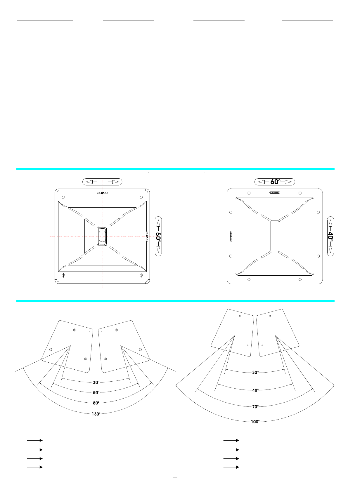
INSTALLAZIONE
INSTALLATION
INSTALLATION
INSTALLATION
Peraumentarelazonadicoperturae
l’SPLmassimoèpossibileaffiancare
piùdiffusoriformandoun
array.
Nellefigura“A”sonoriportatealcune
regolesulposizionamentodei
diffusoriperminimizzarel’interazione
traletrombedicasseadiacentied
ottenereunarispostaomogeneasu
tuttol’angolodicoperturadell’array.
Èimportantericordareche
l’allineamentonello
stessopianoverticale(rispettoal
puntodiascolto)èimportanteperchè
evitarotazionidifaseindesiderate
delleondeacustichenellazonadi
incrocio,chepossonocausareuna
rispostainfrequenzanonuniforme.
VERVE
SUB-SATELLITE
VERVE10A
VERVE12A
VERVE15A
Severalloudspeakerscanbe
VERVE Pouraugmenterlazonede
combinedtocreateanarrayto
increasethecoverageareaand
maximumSPL.
Figure"A"showsseveralbasicrules
forpositioningtheloudspeakersto
minimiseinterferencebetweenthe
hornsofadjacentenclosuresandto
obtainauniformresponseoverthe
entiredispersionangleofthearray.
Itisimportanttoalignthesubwoofer
andsatellitesinthesamevertical
plane(withrespecttothelistening
position):thisprecautionwilleliminate
undesirablephaserotationsofthe
soundwavesattheintersection
points,whichcanresultinnonuniformfrequencyresponse.
couvertureetleNPAmaximum,ilest
possibled'utiliserplusieursdiffuseurs
VERVE
réseau.
Lafigure"A"reportecertainesrègles
surlamanièredepositionnerleshautparleursafindeminimiserl'interaction
entrelespavillonsd'enceintes
adjacentsetd'obteniruneréponse
homogènesurl'anglecompletde
couvertureduréseau.
L'alignementdusur
unmêmeplanvertical(parrapportau
pointd'écoute)estfondamental,caril
permetd'éviterlesrotationsdephase
desondesacoustiquesnondésirées
danslazonedecroisement,enraison
desquelleslaréponseenfréquence
pourraitnepasêtreuniforme.
demanièreàformerun
SUB-SATELLITE
VERVE152A
80°
VERVE215A
ZurErhöhungderReichweiteunddes
max.Schalldrucks(SPL)können
mehrereLautsprecher
aneinandergereihtwerden(Array).
InAbb.“A”sindeinigebeider
AufstellungderBoxenzubeachtende
Regelndargestellt,umdieKopplung
zwischendenTrichtern
nebeneinanderstehenderBoxenauf
einMinimumzureduzierenundein
gleichmäßigesFrequenz-und
AbstrahlverhaltendesArrayszu
erhalten.
Eswirddaranerinnert,dassdie
Ausrichtungin
derselbenvertikalenEbene(bezogen
aufdenHörpunkt)wichtigist,um
ungewünschtePhasendrehungender
SchallwellenimCrossover-Bereich
zuvermeiden,diezueinem
ungleichmäßigenFrequenzgang
führenkönnten.
SUB-SATELLITE
VERVE
VERVE10A
VERVE12A
VERVE15A
30°
50°
80°
130°
WITH50°HORNPOSITION
WITH80°HORNPOSITION
TOTALCOVERAGEWITH50°HORNPOSITION
TOTALCOVERAGEWITH80°HORNPOSITION
fig.A
4
30°
40°
70°
100°
VERVE152A
VERVE215A
WITH40°HORNPOSITION
WITH60°HORNPOSITION
TOTALCOVERAGEWITH40°HORNPOSITION
TOTALCOVERAGEWITH60°HORNPOSITION
Page 8
5
CONNESSIONI
CONNECTIONS
BRANCHEMENTS
ANSCHLÜSSE
XLRfemaleplug
2
3
1
XLRmaleplug
1
3
2
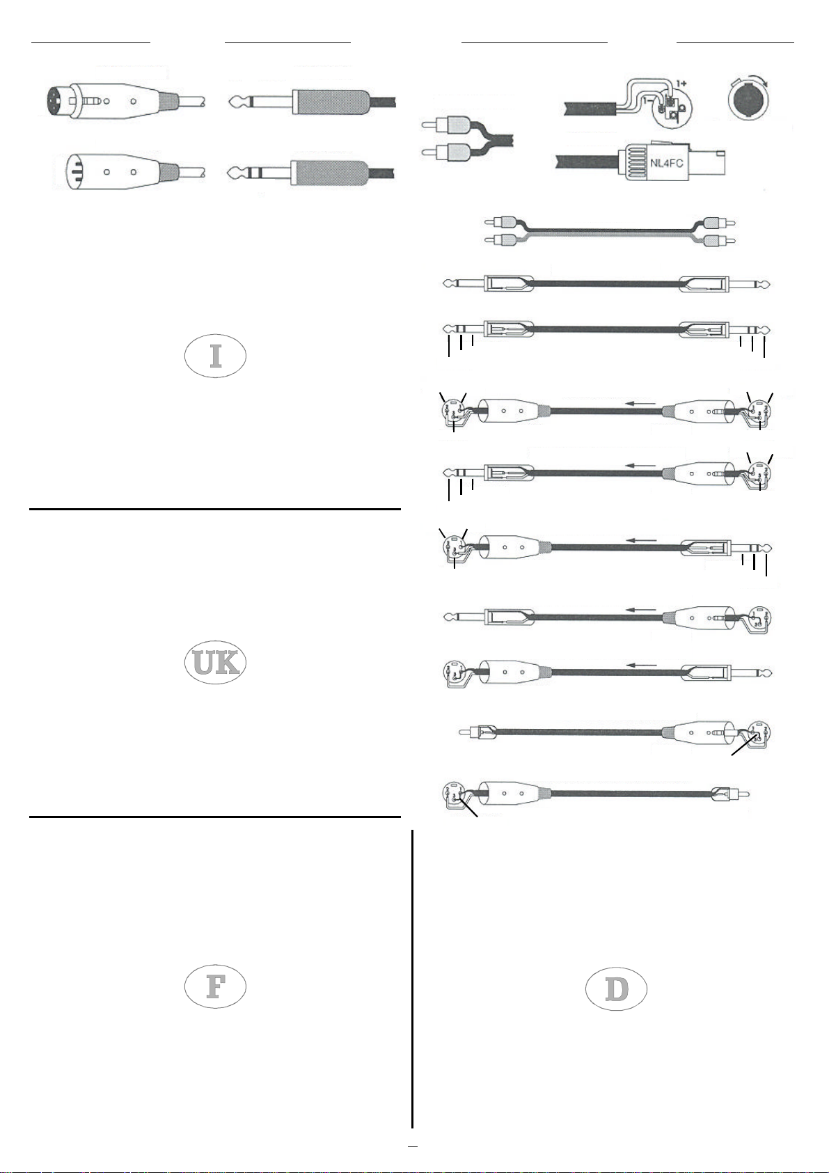
Iconnettorihannotrepolievengonoutilizzatiquasisemprepercondurre
XLR
SleeveTip
SleeveTip
Ring
TSjackplug
TRSjackplug
segnalimonobilanciati;itrepolicorrispondonorispettivamenteallamassa(1),
alsegnalepositivo(2)ealsegnalenegativo(3).
SPEAKON
èunconnettoreadattoappositamenteperilcollegamentotrafinali
dipotenzaealtoparlanti;inserendolonell’appositapresasibloccainmododa
impedireundistaccoaccidentale;inoltreèdotatodiprotezionecontroscosse
elettricheegarantisceunacorrettapolarizzazione.
Glinonpossonoesserebilanciatiperchèhannosoloduepoli:segnale
RCA
(puntacentrale)emassa(marginecircolare),quindisonoconnettorimono
sbilanciati.
Isonoconnettoritipicipertrasportareduesegnaliseparatididuecanali,
JACK
destraesinistra,conununicoconnettoreequindipossonoessereditipo
monoostereo.Ijackmono(TS)dettianchesbilanciatisidifferenzianoda
quellistereo(TRS)obilanciatiperlalorocomposizione.Iprimihannolo
spinottodivisoindueparti,puntaemassa(TipeSlave)allequalisono
collegatiiduepoli;ijackstereoobilanciatisonoinvecedivisiintreparti,in
quantohannounanellocentrale(Ring)dacui(TRS)collegatoadunsecondo
filochecostituisceilterzopolo(polonegativo).
The3-poleXLRconnectorsarealmostalwaysusedforconductingmonobalancedsignals;thethreepolescorrespondrespectivelytoground(1),the
positivesignal(2)andthenegativesignal(3).
SPEAKONisaconnectorwhichisspeciallyadaptedforconnectingpower
terminalstoloudspeakers;wheninsertedinanappropriatesocket,itlocksso
astopreventaccidentaldisconnection;moreover,itisequippedwith
protectionagainstelectricalshocksandguaranteesthecorrectpolarisation.
TheRCAcannotbebalancedastheyhavejusttwopoles:signal(centralpoint)
andground(perimeter);theyarethereforeunbalancedmonoconnectors.
RCAphonojack
SLEEVE-GROUND
RING-COLD(-)
TIP-HOT(+)
2-HOT(+)/1-GROUND
SLEEVE-GROUND
RING-COLD(-)
TIP-HOT(+)
2-HOT(+)/1-GROUND
3-COLD(-)
SPEAKON
RCAPHONOJACKS
PHONOCABLE
UNBALANCEDJACKCABLE
BALANCEDJACKCABLE
BALANCEDXLRCABLE
XLRMALE XLRFEMALE
BALANCEDJACKTOFEMALEXLRCABLE
XLRFEMALE
BALANCEDJACKTOMALEXLRCABLE
XLRMALE
UNBALANCEDJACKTOFEMALEXLRCABLE
XLRFEMALE
UNBALANCEDJACKTOMALEXLRCABLE
pluginandrotate
beforelocking
SLEEVE-GROUND
RING-COLD(-)
TIP-HOT(+)
1-GROUND/2-HOT(+)
1-GROUND/2-HOT(+)
SLEEVE-GROUND
RING-COLD(-)
TIP-HOT(+)
3-COLD(-)3-COLD(-)
3-COLD(-)
TheJACKSaretypicalconnectorsforthetransportingoftwoseparatesignals
throughtwochannels,leftandright,usingasingleconnectorandtherefore
theycanbeeithermonoorstereo.Monojacks(TS),alsoknownas
unbalancedjacks,arerecognisablefromstereoorbalancedjacks(TRS)by
theircomposition.Thepointofthemonojacksisdividedintotwoparts,tipand
ground(TipandSlave)towhichthetwopolesareconnected;thestereoor
balancedjacksaredividedinthreeparts,astheyhaveacentralring(Ring)
whichisconnectedtoasecondwire,thethird(negative)pole.
LesconnecteursXLRpossèdenttroispôlesetservent,engénéral,à
transmettrelessignauxmonobalancés;lestroispôlescorrespondent,dans
l'ordre,àlamasse(1),ausignalpositif(2)etausignalnégatif(3).
LeconnecteurSPEAKONaétéspécialementconçupourlebranchementdes
terminauxdepuissanceetdeshauts-parleurs.Placédanslapriseadéquate,il
sertàprévenirundébranchementaccidentel.Deplus,ilestpourvud'un
systèmedeprotectioncontrelessecoussesélectriquesetgarantitunniveau
depolarisationcorrect.
LesRCAnepeuventêtrebalancéscarilsnepossèdentquedeuxpôles:le
signal(pointecentrale)etlamasse(margecirculaire).Cesontdoncdes
connecteursdetypemonononbalancés.
LesprisesJACKsontdesconnecteurstypiquesetserventàtransporterles
deuxsignauxséparésdesdeuxcanaux,droiteetgauche,àtraversunseulet
uniqueconnecteur.Ilspeuventêtredetypemonooustéréo.Lesprisesmono
(TS),appelésaussinonbalancées,deparleurcomposition,sedistinguentde
cellesstéréo(TRS)oubalancées.Eneffet,lespremièresontlaprisedivisée
endeuxparties,pointeetmasse(TipetSlave),auxquelleslesdeuxpôles
sontbranchés.Parcontre,lesprisesjackstéréooubalancéessontdivisées
entroisparties:ellespossèdentunebaguecentrale(Ring),àlaquelle(TRS)
estbranchéàundeuxièmefilquiconstitueletroisièmepôle(pôlenégatif).
XLRMALE
UNBALANCEDPHONOTOFEMALEXLRCABLE
LINKPINS1&3
XLRFEMALE
UNBALANCEDPHONOTOMALEXLRCABLE
XLRMALE
LINKPINS1&3
RCAPHONO
DieXLR-EingängehabendreiPoleundwerdenfastimmerzurÜbertragung
vonausgeglichenenMono-Signalenbenutzt;diedreiPoleentsprechen
jeweilsderMasse(1),dempositivenSignal(2)unddemnegativenSignal(3).
SPEAKONisteinEingang,derextrafürdieVerbindungzwischen
LeistungsendenundLautsprechersangepasstwurde.Wennerindie
entsprechendeBuchseeingestecktwird,dannblockierterso,dassernicht
ungewolltherausgezogenwerdenkann.Eristaußerdemmiteinem
StromschlagschutzausgerüstetundgewährleistetdierichtigePolarisation.
DieRCAkönnennichtausgeglichensein,dasienurzweiPolehaben:Signal
(Leiter)undMasse(Mantel),eshandeltsichalsoumnichtausgeglichene
Mono-Eingänge.
DieJACKsindtypischeEingänge(Klinke),umzweigetrennteSignalenvon
zweiKanälen,rechtsundlinks,miteinemeinzigenEingangzuübertragenund
könnenvondaherMonooderStereosein.DieMono-Jacks(TS),auchals
nichtausgeglichenbezeichnet,unterscheidensichinihremAufbauvonden
Stereo-Jacks(TSR)bzw.denausgeglichenenKlinkensteckern.Dieersten
habeneinenzweigeteiltenStift,LeiterundMasse(TipundSlave),andenen
diebeidenPoleangeschlossensind.DieStereo-bzw.dieausgeglichenen
JacksbestehenausdreiTeilen,dasieeinezentraleSpule(Ring)haben,an
denen(TRS)aneinenzweitenDrahtangeschlossenist,derdendrittenPol
bildet(negativerPol).
Page 9

6
PANNELLOCONNESSIONI
BUCHSENFELD
CONNECTIONPANEL
PANNEAUCONNEXIONS
VOLUME
PROCESSEDACTIVEREINFORCEMENTMONITOR
OUT
XLR
1-Gnd
LINK
2-Hot
3-Cold
IN
GNDLIFT
LIMITER
1)VOLUME:
Regolaillivellogeneraledel
0dB
+3dB
OFF
ON
segnale
2)GND/LIFT:
Interruttoreperla
separazioneelettricatrailcircuitodi
massaeilcircuitoditerraondeevitare
possibiliLOOPdimassacausadi
fastidiosironzii.
3)LOW-MID-HIGH:
Controlliditonoche
permettonodimodificarelatimbricadel
suono.
4)IN/OUT:
Presediingresso/uscita
bilanciateelettronicamente;LINEIN
consenteilcollegamentodiunsegnale
preamplificatocomequelloinuscitadaun
mixer;LINEOUTpermetteilcollegamento
dipiùdiffusoriconlostessosegnale.
5)SIGNAL-LIMITER-THERMAL:
Signal(ledverde):
Indicalapresenzadel
segnaleiningresso.
Limiter(ledarancio):
Siilluminaquando
ilsistemavieneutilizzatoallimitedella
potenzamediasopportabiledagli
altoparlanti;inquestocasoilsegnale
vieneridottoinmodogradualefinoa
riportarel’altoparlanteentroilimitidi
sicurezza.Siconsigliadioperarein
condizioniincuiilLedlampeggisolo
occasionalmente.L’accensionedelLed
“arancio”puòancheindicareil
malfunzionamentodell’amplificatore
dovutoacorto-circuitoinuscita.
Thermal(ledrosso):
Siilluminaquando
latemperaturainternadell’amplificatore
raggiungeillimitemassimo:inquesto
casoilsegnalevieneridotto
automaticamenteinmodograduale,finoa
riportarelatemperaturadell’amplificatore
entroilimitidisicurezza.
6)LIMITER(VERVE8MA): L’accensione
delledindicacheilsegnaleharaggiunto
lasogliadisaturazionenellostadiodi
amplificazioneelaprotezioneentrain
funzione.
7)LIMIT/PRT:
illedLimitersiaccende
quandoilsistemavieneutilizzatoallimite
dellapotenzamediasopportabiledagli
altoparlanti;inquestocasoilsegnale
vieneridottoinmodogradualefinoa
riportarel’altoparlanteentroilimitidi
sicurezza:siconsigliadioperarein
condizioniincuiilledsiillumini
saltuariamente;illedPrtsiaccende
quandolatemperaturainterna
dell’amplificatoreraggiungeillimite
massimo:inquestocasoilsegnaleviene
ridottoautomaticamenteinmodo
graduale,finoariportarelatemperatura
entroilimitidisicurezza.L’accensionedel
ledpuòancheindicareil
malfunzionamentodell’amplificatore
dovutoacorto-circuitoinuscita.
8)PEAK:
l’accensionediquestoledindica
cheillivellodelsegnaleèprossimoalla
saturazione.
IN OUT
1-Gnd
12
2-Hot
3
3-Cold
ON OFF
1)VOLUME:
GND
LIFT
Adjustthegenerallevelof
LINK PEAKPWR
230V50Hz
T3.15A250V
600VA
thesignal.
2)GND/LIFT:
Switchtoisolatethechassis
groundandthesignalgroundtoavoid
groundloops,whichcancausehum
problems.
3)LOW-MID-HIGH:
4)IN/OUT:
Tonecontrols
Electronicallybalancedinput
andoutputconnectors;LINEINenables
theconnectionofapreamplifiedsignal
suchasamixeroutput;LINEOUTenables
thesamesignaltoberelayedtoseveral
speakers.
5)SIGNAL-LIMITER-THERMAL:
Signal(greenLED):
Showsinputsignal
presence.
Limiter(orangeLED):
Thisswitcheson
whenthesystemisusedatthelimitofthe
averagepowerthattheloudspeakers
tolerate;inthiscasethesignalisgradually
reduceduntiltheloudspeakeriswithin
safetylimits.Itisadvisedtooperatewhen
theLEDonlyflashesoccasionally.When
theorangeLEDswitchesonitcanalso
indicateamplifiermalfunctiondueto
outputshort-circuit.
Thermal(redLED):
Thisswitcheson
whentheamplifier'sinternaltemperature
reachesthemaximumlimit:inthiscase
thesignalisautomaticallyandgradually
reduceduntiltheamplifiertemperatureis
withinsafetylimits.
6)LIMITER(VERVE8MA) : Theled
illuminatestoindicatethatthesignalhas
reachedthesaturationthresholdinthe
amplificationstagesothegainlimitation
protectionhasbeenactivated.
7)LIMIT/PRT:
theLEDilluminateswhen
thesystemisbeingusedatthelimitsofthe
averagepowertoleranceofthe
loudspeakers;thesignalisthengradually
reduceduntilitiswithinthesafetylimitsof
theloudspeaker:itisadvisedtooperate
thesystemsothatthisLEDilluminates
onlyoccasionally;thePRTLED
illuminateswhentheinternaltemperature
oftheamplifierreachesthemaximum
limit:thesignalisthenautomatically
graduallyreduced,untilthetemperatureis
onceagainwithinsafetylimits.The
illuminationofthisLEDmayindicatea
malfunctionoftheamplifiercausedbya
shortcircuit.
8)PEAK:
theLEDilluminatestoindicate
thesignallevelisclosetosaturation.
HIGH MID LOW
VOL
0 0 0
-12
0
-28
+6-15+3dB
MADE
IN
ITALY
RISKOFELECTRICSHOCK
DONOTOPEN
1)VOLUME:
-15 +15 +6-15
BUILTINAMP.:
FREQ.RANGE(@-6dB):
MAX.SPL(@1m):
SENSITIVITY(@1W,1m):
PRT
LIMIT
PROCESSEDACTIVE
REINFORCEMENT
LOUDSPEAKER
600W(LF)150W(HF)
43Hz-20kHz
129dB
101dB
Réglantleniveaugénéraldu
signal.
2)GND/LIFT:
Interrupteurpourla
séparationélectriqueentrelecircuitde
masseetlecircuitdeterreafind'éviterde
possibles"LOOPS"(boucles)demasseà
l'originederonflementsgênants.
3)LOW-MID-HIGH:
Réglagedetonalité
permettantdemodifierletimbreduson.
4)IN/OUT:
Prisesd'entrée/sortie
équilibréesélectroniquement;LINEIN
permetderaccorderunsignalpréamplifiécommeceluiensortied'un
mixeur;LINEOUTpermetderaccorder
plusieursdiffuseursaveclemêmesignal.
5)SIGNAL-LIMITER-THERMAL:
Signal(DELvert):
Indiquelaprésence
dusignald'entrée.
Limiter(DELorange):
S'allumelorsque
lesystèmeestutiliséàlalimitedela
puissancemoyennesupportableparles
haut-parleurs,danscecaslesignal
diminuedefaçonprogressivejusqu'àce
qu'ilramènelehaut-parleurdansles
limitesdesécurité.Ilestconseilléd'opérer
dansdesconditionstellesqueleDelne
clignotequ'occasionnellement.
L'éclairageduDel«orange»peutaussi
indiquerunmauvaisfonctionnementde
l'amplificateurdûàuncourt-circuiten
sortie.
Thermal(DELrouge):
S'allumelorsque
latempératureinternedel'amplificateur
atteintlalimitemaximaleetdanscecasle
signaldiminueautomatiquementde
façonprogressivejusqu'àcequ'ilramène
latempératuredel'amplificateurdansles
limitesdesécurité.
6)LIMITER(VERVE8MA) :L’allumagedu
témoinLEDindiquequelesignalarejoint
leseuildesaturationd'amplificationetque
laprotectionentreenfonction.
7)LIMIT/PRT
:LaLEDdelimitation
s'allumelorsquelesystèmeestutiliséàla
limitedelapuissancemoyennesupportée
parleshauts-parleurs;danscecas,le
signalseraréduitdemanièregraduelle
jusqu'àramenerlehaut-parleurà
l'intérieurdeslimitesdesécurité.Ilest
conseillédefairefonctionnerl'appareilde
manièreàcequelaLEDnes'allumeque
demanièrepassagère.LaLEDPrt
s'allumelorsquelatempératureinternede
l'amplificateuratteintlalimitemaximale:
danscecas,lesignalsubirauneréduction
automatiquegraduelle,etce,jusqu'à
ramenerlatempératureàl'intérieurdes
limitesdesécurité.LaLEDpeuts'allumer
aussipourindiquerunmauvais
fonctionnementdel'amplificateurdûàun
court-circuitquiaeulieuensortie.
8)PEAK:
silaLEDs'allume,celasignifie
queleniveaudusignalestprochedela
saturation.
GREEN-SIGNAL
ORANGE-LIMITER
RED-THERMAL
LOW
HIGH
OUT
IN
1-Gnd
2-Hot
3-Cold
1)VOLUME:
0
VOL
-15 +15
-15 +15
12
3
PROCESSEDACTIVE
REINFORCEMENTLOUDSPEAKER
+3dB
0
BUILTINAMP.:
FREQ.RANGE(@-6dB):
MAX.SPL(@1m):
SENSITIVITY(@1W,1m):
0
RISKOFELECTRICSHOCK
MADE
IN
ITALY
LINK
GND
LIFT
OFF
ON
DONOTOPEN
230V50Hz220VA
T2.5A250V
Regelungdesallgemeinen
250W(LF)100W(HF)
50Hz-20kHz
121dB
97dB
Lautstärke-Signalpegels.
2)GND/LIFT:
Schalterzurelektrischen
TrennungvonMasse-undErdkreiszur
VermeidungmöglicherMasse-LOOPS
mitstörendemBrummen.
3)LOW-HIGH:
Tonsteuerungenzur
EinstellungdesKlangbilds.
4)IN/OUT:
ElektronischsymmetrierteEin/Ausgangsbuchsen;LINEINermöglicht
denAnschlusseinesvorverstärkten
SignalswiedasimAusgangauseinem
Mixer;LINEOUTermöglichtden
AnschlussmehrererLautsprechermit
demselbenSignal.
5)SIGNAL-LIMITER-THERMAL:
Signal(grüneLED-Anzeige):
Zeigtdie
SignalauslösungamEingangan.
Limiter(orangeneLED-Anzeige):
Leuchtetauf,wenndasSystemim
Grenzbereichderdurchschnittlichen
Leistungarbeitet,dievonden
Lautsprecherntragbarist;indiesemFall
wirddasSignalschrittweisereduziert,bis
derLautsprecherwiederim
vorgesehenenSicherheitsbereich
arbeitet.Eswirdempfohlen,sozu
arbeiten,dassdieLED-Anzeigenur
fallweiseblinkt.DasAufleuchtender
“orangefarbigen”LED-Anzeigekannauch
aufeineStörungdesVerstärkersinfolge
einesKurzschlussesamAusgang
hinweisen.
Thermal(roteLED-Anzeige):
Leuchtet
auf,wenndieInnentemperaturdes
VerstärkersdieHöchstgrenzeerreicht
hat;indiesemFallwirddasSignal
automatischschrittweisereduziert,bis
sichdieTemperaturdesVerstärkers
wiederinnerhalbderSicherheitsgrenzen
bewegt.
6)LIMITER(VERVE8MA):Das
AufleuchtenderLEDbedeutet,dassdas
SignalinderVerstärkungsstufedie
Sättigungsschwelleerreichthatunddie
Sicherungaktiviertwird
7)LIMIT/PRT:
DieLEDLimiterleuchtet,
wenndasSystemandenGrenzendervon
denLautsprechernerträglichenmittleren
Leistungbenutztwird.IndiesemFallwird
dasSignalallmählichverringert,bisder
Lautsprecherwiederinnerhalbder
Sicherheitsgrenzenarbeitet:Eswird
empfohlen,unterBedingungenzu
arbeiten,indenendieLEDnurhinund
wiederleuchtet.DieLEDPrtleuchtetauf,
wenndieTemperaturimVerstärkerden
maximalenGrenzwerterreicht:Indiesem
FallwirddasSignalautomatischund
allmählichverringert,bisdieTemperatur
sichwiederinnerhalbder
Sicherheitsgrenzwertebefindet.Das
LeuchtenderLEDkannauchaufeine
FunktionsstörungdesVerstärkers
aufgrundeinesKurzschlussesim
Ausganghinweisen.
8)PEAK:
WenndieseLEDleuchtet,dann
istderSignalpegelinSättigungsnähe.
Page 10

7
THERM
PANNELLOCONNESSIONI
BUCHSENFELD
CONNECTIONPANEL
PANNEAUCONNEXIONS
LIMIT
PHASE
0°
180°
-9
0
+3
VOL
+6dB
R
HP
FILT.
OUT
OUT
IN
9)LIMIT/THERM:
illedLimitersi
accendequandoilsistemavieneutilizzato
allimitedellapotenzamediasopportabile
daglialtoparlanti;inquestocasoilsegnale
vieneridottoinmodogradualefinoa
riportarel’altoparlanteentroilimitidi
sicurezza:siconsigliadioperarein
condizioniincuiilledsiillumini
saltuariamente;illedTHERMsiaccende
quandolatemperaturainterna
dell’amplificatoreraggiungeillimite
massimo;inquestocasoilsegnaleviene
ridottoautomaticamenteinmaniera
graduale,finoariportarelatemperatura
dell’amplificatoreentroilimitidisicurezza.
10)PHASE:
switchcheconsentedi
ottimizzarel’allineamentodifase,cioèdi
ottenereunarispostainfrequenza
uniformenellazonadiincrociotrasube
satellite.
11)VOL:
potenziometrodivolumeche
regolaillivellogeneraledelsegnale.
12)HPFILTEREDOUT:
uscitaper
prelevareilsegnalefiltratodainviaread
unsatelliteamplificato;inquestomodosi
evitacheiduediffusoricollegatioperino
peruntrattonellostessointervallodi
frequenza,ottenendounarisposta
complessivasenzainterferenze.
13)OUT_link_IN:
presediingressoed
uscitabilanciateelettronicamente;la
presadiingresso“IN”perlaconnessione
distrumenticonsegnalipreamplificati
sbilanciatiobilanciati(comequelliin
uscitadiunmixer);lapresadiuscita
“OUT”puòessereutilizzatapereffettuare
ilcollegamentoinparalleloconaltri
subwoofers(inquestocasoil
collegamentoconunsatellitepuò
avveniresolamenteattraversolapresa
“HPFILT.OUT)
14)GNDLIFT:
interruttoreperla
separazioneelettricatrailcircuitodi
massaedilcircuitoditerra.
L
GND
LIFT
9)LIMIT/THERM:
theLEDilluminates
whenthesystemisbeingusedatthelimits
oftheaveragepowertoleranceofthe
loudspeakers;thesignalisthengradually
reduceduntilitiswithinthesafetylimitsof
theloudspeaker:itisadvisedtooperate
thesystemsothatthisLEDilluminates
onlyoccasionally;theTHERMLED
illuminateswhentheinternaltemperature
oftheamplifierreachesthemaximum
limit:thesignalisthenautomatically
graduallyreduced,untilthetemperatureis
onceagainwithinsafetylimits.
10)PHASE:
switchwhichallowsforthe
optimisationofphasealignment-thatis,
toobtainauniformfrequencyresponsein
thecrossoverzonebetweensuband
satellite.
11)VOL:
volumecontrolwhichregulates
thegenerallevelofthesignal.
12)HPFILTEREDOUT:
outputfortaking
thefilteredsignalandsendingittoan
amplifiedsatellite;thisavoidshavingthe
twoconnectedspeakersoperatewithin
thesamefrequencyinterval,andthus
obtainsacomplexresponsewithout
interference.
13)OUT_link_IN:
electronicallybalancedinputandoutputconnectors;the
“IN”socketisfortheconnectionof
instrumentsutilisingbalancedor
unbalancedpreamplifiedsignals(suchas
amixeroutput);the“OUT”socketcanbe
usedforconnectinginparallelwithother
subwoofers(connectionwithasatellite
canonlythenbemadeusingthe“HPFILT.
OUT”socket)
14)GNDLIFT:
switchtoelectricallyisolate
thechassisgroundandthesignalground.
HP
FILT.
OUT
OUT
IN
PWR
9)LIMIT/PRT:
LaLEDdelimitation
s'allumelorsquelesystèmeestutiliséàla
limitedelapuissancemoyennesupportée
parleshauts-parleurs;danscecas,le
signalseraréduitdemanièregraduelle
jusqu'àramenerlehaut-parleurà
l'intérieurdeslimitesdesécurité.Ilest
conseillédefairefonctionnerl'appareilde
manièreàcequelaLEDnes'allumeque
demanièrepassagère.LaLEDTHERM
s'allumelorsquelatempératureinternede
l'amplificateuratteintlalimitemaximale.
Danscecas,lesignalsubiraune
réductionautomatiquegraduelle,etce,
jusqu'àramenerlatempératurede
l'amplificateuràl'intérieurdeslimitesde
sécurité.
10)PHASE:
interrupteurquisertà
optimiserl'alignementdelaphase,
autrementdit,d'obteniruneréponsedela
fréquenceuniformedanslazonede
croisemententrelesubetlesatellite.
11)VOL:
potentiomètredevolumequi
règleleniveaugénéraldusignal.
12)HPFILTEREDOUT:
sortiequiala
fonctiondepréleverlesignalfiltréqui
devraêtreenvoyéàunsatelliteamplifié;
decettemanière,l'onévitequeles
diffuseursquiysontbranchésnese
superposentpendantunmomentà
l'intérieurdumêmeintervallede
fréquence,lerésultatestuneréponse
totalesansinterférences.
13)OUT_link_IN:
prise d'entréeetsortie
balancéesélectroniquement;laprise
d'entrée«IN»permetdebrancherdes
instrumentsayantdessignaux
préamplifiésbalancésounon(comme
ceuxensortied'unetabledemixage);la
prisedesortie«OUT»peutêtreutilisée
poureffectuerunbranchementd'autres
subwoofersenparallèle(danscecas,le
branchementausatellitenepeutêtrefait
qu'àtraverslaprise«HPFILT»OUT).
14)GNDLIFT:
interrupteurquisertàla
séparationélectriqueentrelecircuitdela
masseetlecircuitdeterre.
9)LIMIT/THERM:
DieLEDLimiter
leuchtet,wenndasSystemanden
GrenzendervondenLautsprechern
erträglichenmittlerenLeistungbenutzt
wird.IndiesemFallwirddasSignal
allmählichverringert,bisderLautsprecher
wiederinnerhalbderSicherheitsgrenzen
arbeitet:Eswirdempfohlen,unter
Bedingungenzuarbeiten,indenendie
LEDnurhinundwiederleuchtet.DieLED
THERMleuchtetauf,wenndie
TemperaturimVerstärkerdenmaximalen
Grenzwerterreicht.IndiesemFallwird
dasSignalautomatischundallmählich
verringert,bisdieTemperatursichwieder
innerhalbderSicherheitsgrenzwerte
befindet..
10)PHASE:
DieserSchaltergestattetdie
OptimierungderPhasenausrichtung,d.h.
einegleichmäßigeFrequenzantwortin
derCrossover-ZonezwischenSubund
Satellite.
11)VOL:
Lautstärken-Potentiometer,der
denallgemeinenSignalpegelregelt.
12)HPFILTEREDOUT:
Ausgangzur
EntnahmedesgefiltertenSignals,dasan
einenverstärktenSatellitengesendet
wird.AufdieseWeisewirdverhindert,
dassdiebeidenangeschlossenen
LautsprecherineinemAbschnittmitdem
gleichenFrequenzintervallarbeiten,
wodurchmaneinestörungsfreie
Gesamtantworterhält.
13)OUT_link_IN:
Elektronisch
ausgeglicheneEin-und
Ausgangsbuchsen.DieEingangsbuchse
“IN”dientfürdenAnschlussvon
Instrumentenmitnichtausgeglichenen
oderausgeglichenenvorverstärkten
Signalen(wieimAusgangeinesMixers).
DieAusgangsbuchse“OUT”kannfürden
Parallelanschlussvonanderen
Subwoofernbenutztwerden(indiesem
FallkanndieVerbindungmiteinem
SatellitennurüberdieBuchse“HPFILT.
OUTerfolgen)
14)GNDLIFT:
Schalterzurelektrischen
TrennungvonMasse-undErdkreis.
Page 11

8
ALIMENTAZIONE
VERSORGUNG
POWERSUPPLY
ALIMENTATION
Primadicollegarel’apparecchioallareteelettricaaccertarsichela
tensionedialimentazionecorrispondaconquellaindicatanelretro
dell’unità.Lapresadialimentazionecomprendeancheunvano
portafusibile.Ifusibilidifettosidevonoessereassolutamente
sostituiticonaltricheabbianovaloreecaratteristicheelettriche
uguali.
Avantdebrancherl'appareilauréseauélectrique,vérifiezquela
tensiond'alimentationcorrespondàcelleindiquéeauderrièrede
l'appareil.Laprised'alimentationinclutmêmelelogementdu
fusible.Lesfusiblesdéfectueuxdoiventêtrenécessairement
remplacésavecdesautresquiontlavaleuretlescaractéristiques
électriqueségales.
Beforeconnectingtheapparatustothemains,makesurethe
supplyvoltagematchestheoneindicatedonthebackofthe
apparatus.Thepowersocketalsoincludesafusebox.Faulty
fusesshallbereplacedonlywithfuseshavingthesameelectrical
featuresandvalue.
PROCESSEDACTIVE
BUILTINAMP.:
FREQ.RANGE(@-6dB):
MAX.SPL(@1m):
SENSITIVITY(@1W,1m):
220-230V50/60Hz
T5AL250V
600VA
120V60Hz
T10AH250V
600VA
MADE
IN
ITALY
RISKOFELECTRICSHOCK
DONOTOPEN
VordemAnschließendesGerätsandasStromnetzüberzeugen
Siesichbitte,dassdieSpeisespannungderrückseitigamGerät
angeführtenentspricht.DieStrombuchseumfasstauchein
Sicherungsfach.DefekteSicherungensindunbedingtdurch
gleichartigeund-wertigezuersetzen.
REINFORCEMENT
LOUDSPEAKER
600W(LF)150W(HF)
43Hz-20kHz
129dB
101dB
PROCESSEDACTIVE
REINFORCEMENT
LOUDSPEAKER
BUILTINAMP.:
FREQ.RANGE(@-6dB):
MAX.SPL(@1m):
SENSITIVITY(@1W,1m):
220-230V50/60Hz
T5AL250V
500VA
MADE
IN
ITALY
RISKOFELECTRICSHOCK
DONOTOPEN
500W(LF)150W(HF)
45Hz-20kHz
125dB
98dB
220-230V50/60Hz
T5AL250V
500VA
120V60Hz
T10AH250V
500VA
RISKOFELECTRICSHOCK
DONOTOPEN
MADEINITALY
PROCESSEDACTIVE
REINFORCEMENT
SUBWOOFER
BUILTINAMP.:
FREQ.RANGE(@-6dB):
MAX.SPL(@1m):
SENSITIVITY(@1W,1m):
120V60Hz
T10AH250V
500VA
500WRMS
38Hz-100Hz
124.5dB
97.5dB
PROCESSEDACTIVE
REINFORCEMENT
SUBWOOFER
120V60Hz
T10AH250V
600VA
220-230V50/60Hz
T5AL250V
600VA
RISKOFELECTRICSHOCK
DONOTOPEN
MADEINITALY
BUILTINAMP.:
FREQ.RANGE(@-6dB):
MAX.SPL(@1m):
SENSITIVITY(@1W,1m):
600WRMS
33Hz-100Hz
126.5dB
98.5dB
Page 12

FREQUENCYRESPONSE
DIAGRAMME
DIAGRAMMI
DIAGRAMS
9
VERVE8MA
VERVE12A
VERVE10A
VERVE15A
VERVE12mA
VERVE152A
VERVE15mA
VERVE15SA
VERVE215A
VERVE18SA
Page 13

10
Horizontalpolardiagrams
0
0
DIAGRAMME
DIAGRAMMI
DIAGRAMS
250 500 1000 2000
Horizontalpolardiagrams
4000 8000 12500 16000
180
190
350
-15
-21
-27
-33
170
160
3
-3
-9
150
30
20
10
0
260
270
280
250
290
240
300
230
310
220
320
210
330
200
340
Verticalpolardiagrams
250 500 1000 2000
180
190
350
-15
-27
-33
-3
-9
-21
170
160
3
150
30
20
10
0
260
270
280
250
290
240
300
230
310
220
320
210
330
200
340
Horizontalpolardiagrams
250 500 1000 2000
140
140
180
190
350
-15
-21
-27
-33
170
160
3
-3
-9
0
150
140
130
120
110
100
90
80
70
60
50
40
30
20
10
200
210
220
260
270
280
250
290
240
300
230
310
320
330
340
130
120
110
100
90
80
70
60
50
40
Verticalpolardiagrams
4000 8000 12500 16000
180
190
350
-15
-21
-27
-33
170
160
3
-3
-9
0
150
140
130
120
110
100
90
80
70
60
50
40
30
20
10
200
210
220
260
270
280
250
290
240
300
230
310
320
330
340
130
120
110
100
90
80
70
60
50
40
Horizontalpolardiagrams
4000 8000 12500 16000
180
190
350
170
160
3
-3
-9
-9
-15
-21
-27
-33
150
30
20
10
0
260
270
280
250
290
240
300
230
310
220
320
210
330
200
340
Verticalpolardiagrams
250 500 1000 2000
180
190
350
-15
-21
-27
-33
170
160
3
-3
-9
150
30
20
10
260
270
280
250
290
240
300
230
310
220
320
210
330
200
340
140
140
180
190
350
-3
-9
-15
-21
-27
-33
170
160
3
150
140
130
120
110
100
90
80
70
60
50
40
30
20
10
0
200
210
220
260
270
280
250
290
240
300
230
310
320
330
340
130
120
110
100
90
80
70
60
50
40
Verticalpolardiagrams
4000 8000 12500 16000
180
190
350
-3
-9
-15
-21
-27
-33
170
160
3
150
140
130
120
110
100
90
80
70
60
50
40
30
20
10
200
210
260
270
280
250
290
240
300
230
310
220
320
330
340
130
120
110
100
90
80
70
60
50
40
Page 14

Horizontalpolardiagrams
0
0
DIAGRAMME
DIAGRAMMI
DIAGRAMS
250 500 1000 2000
Horizontalpolardiagrams
4000 8000 12500 16000
180
190
350
-15
-21
-27
-33
170
160
3
-3
-9
150
30
20
10
0
260
270
280
250
290
240
300
230
310
220
320
210
330
200
340
Verticalpolardiagrams
250 500 1000 2000
180
190
350
-15
-21
-27
-33
170
160
3
150
-3
-9
0
140
30
20
10
260
270
280
250
290
240
300
230
310
220
320
210
330
200
340
Horizontalpolardiagrams
250 500 1000 2000
140
40
40
130
50
130
50
120
60
120
60
110
70
110
100
70
100
80
80
180
190
350
-15
-21
-27
-33
170
160
3
-3
-9
150
140
130
120
110
100
90
80
70
60
50
40
30
20
10
0
200
210
220
230
240
250
260
90
270
280
290
300
310
320
330
340
Verticalpolardiagrams
4000 8000 12500 16000
180
190
350
-15
-27
-33
-3
-9
-21
0
170
160
3
150
140
130
120
110
100
90
80
70
60
50
40
30
20
10
200
210
220
230
240
250
260
90
270
280
290
300
310
320
330
340
Horizontalpolardiagrams
4000 8000 12500 16000
180
190
350
-15
-21
-27
-33
170
160
3
-3
-9
0
150
30
20
10
260
270
280
250
290
240
300
230
310
220
320
210
330
200
340
Verticalpolardiagrams
250 500 1000 2000
180
190
350
-15
-21
-27
-33
170
160
3
-3
-9
150
30
20
10
260
270
280
250
290
240
300
230
310
220
320
200
210
6
330
340
140
140
180
190
350
-15
-21
-27
-33
170
160
3
-3
-9
150
140
130
120
110
100
90
80
70
60
50
40
30
20
10
0
200
210
220
260
270
280
250
290
240
300
230
310
320
330
340
130
120
110
100
90
80
70
60
50
40
Verticalpolardiagrams
4000 8000 12500 16000
180
190
350
-15
-21
-27
-33
170
160
3
-3
-9
150
140
130
120
110
100
90
80
70
60
50
40
30
20
10
200
210
220
260
270
280
250
290
240
300
230
310
320
330
340
130
120
110
100
90
80
70
60
50
40
11
Page 15

12
DIAGRAMME
DIAGRAMMI
DIAGRAMS
Horizontalpolardiagrams
0
0
250 500 1000 2000
Horizontalpolardiagrams
4000 8000 12500 16000
180
190
350
-15
-21
-27
-33
170
160
3
-3
-9
150
30
20
10
0
260
270
280
250
290
240
300
230
310
220
320
210
330
200
340
Verticalpolardiagrams
250 500 1000 2000
180
190
350
-15
-21
-27
-33
170
160
3
-3
-9
150
30
20
10
0
260
270
280
250
290
240
300
230
310
220
320
210
330
200
340
Horizontalpolardiagrams
250 500 1000 2000
140
140
180
190
350
-15
-21
-27
-33
170
160
3
-3
-9
0
150
140
130
120
110
100
90
80
70
60
50
40
30
20
10
200
210
220
260
270
280
250
290
240
300
230
310
320
330
340
130
120
110
100
90
80
70
60
50
40
Verticalpolardiagrams
4000 8000 12500 16000
180
190
350
-15
-27
-33
-21
170
160
3
150
-3
-9
0
140
130
120
110
100
90
80
70
60
50
40
30
20
10
200
210
220
260
270
280
250
290
240
300
230
310
320
330
340
130
120
110
100
90
80
70
60
50
40
Horizontalpolardiagrams
4000 8000 12500 16000
180
190
350
-15
-21
-27
-33
170
160
3
-3
-9
150
30
20
10
0
260
270
280
250
290
240
300
230
310
220
320
210
330
200
340
Verticalpolardiagrams
250 500 1000 2000
180
190
350
-15
-21
-27
-33
170
160
3
-3
-9
150
30
20
10
260
270
280
250
290
240
300
230
310
220
320
210
330
200
340
140
140
180
190
350
-15
-27
-33
-21
170
160
3
-3
-9
150
140
130
120
110
100
90
80
70
60
50
40
30
20
10
0
200
210
220
250
260
270
280
290
240
300
230
310
320
330
340
130
120
110
100
90
80
70
60
50
40
Verticalpolardiagrams
4000 8000 12500 16000
180
190
350
-15
-21
-27
-33
170
160
3
-3
-9
150
140
130
120
110
100
90
80
70
60
50
40
30
20
10
200
210
220
260
270
280
250
290
240
300
230
310
320
330
340
130
120
110
100
90
80
70
60
50
40
Page 16

13
DIAGRAMME
DIAGRAMMI
DIAGRAMS
0
0
Horizontalpolardiagrams
250 500 1000 2000
Horizontalpolardiagrams
4000 8000 12500 16000
180
190
350
-3
-9
-15
-21
-27
-33
170
160
3
0
150
140
40
30
20
10
260
270
280
250
290
240
300
230
310
220
320
210
330
200
340
Verticalpolardiagrams
250 500 1000 2000
180
190
350
-15
-27
-33
-3
-9
-21
170
160
3
0
150
140
40
30
20
10
260
270
280
250
290
240
300
230
310
220
320
210
330
200
340
Horizontalpolardiagrams
250 500 1000 2000
130
50
130
50
120
60
120
60
110
110
100
70
100
70
180
190
350
-15
-27
-33
-21
170
160
3
-3
-9
0
150
140
130
120
110
100
90
80
70
60
50
40
30
20
10
200
210
220
230
240
250
260
90
80
270
280
290
300
310
320
330
340
Verticalpolardiagrams
4000 8000 12500 16000
180
190
350
-15
-21
-27
-33
170
160
3
150
-3
-9
0
140
130
120
110
100
90
80
70
60
50
40
30
20
10
200
210
220
230
240
250
260
90
80
270
280
290
300
310
320
330
340
Horizontalpolardiagrams
4000 8000 12500 16000
180
190
350
-3
-9
-15
-21
-27
-33
170
160
3
0
150
140
30
20
10
260
270
280
250
290
240
300
230
310
220
320
210
330
200
340
Verticalpolardiagrams
250 500 1000 2000
180
190
350
-15
-27
-33
-3
-9
-21
170
160
3
150
140
30
20
10
260
270
280
250
290
240
300
230
310
220
320
210
330
200
340
180
190
350
-15
-27
-33
-21
170
160
3
-3
-9
0
150
140
130
120
110
100
90
80
70
60
50
40
30
20
10
200
210
220
260
270
280
250
290
240
300
230
310
320
330
340
130
120
110
100
90
80
70
60
50
40
Verticalpolardiagrams
4000 8000 12500 16000
180
190
350
-15
-21
-27
-33
170
160
3
150
-3
-9
140
130
120
110
100
90
80
70
60
50
40
30
20
10
200
210
220
260
270
280
250
290
240
300
230
310
320
330
340
130
120
110
100
90
80
70
60
50
40
Page 17

14
1_GRIGLIAMETALLICADIPROTEZIONE
LAYOUT
2_TROMBA+DRIVER
3_TUBIDIACCORDO
4_MANIGLIE
5_WOOFER
6_PANNELLOCONNESSIONI
7_FLANGIAPERSTATIVO
1_METALPROTECTIVEGRILL
2_HORN+DRIVER
3_TUNEDPORTS
4_HANDLES
5_WOOFER
6_CONNECTIONSPANEL
7_FLANGEFORSTAND
1_GRILLAGEMÉTALLIQUE
2_TROMPE+DRIVER
3_TUBESD’ACCORD
4_POIGNÉES
5_WOOFER
6_PANNEAUDESCONNEXIONS
7_FLASQUEPOURSTATIF
1_METALLSCHUTZGITTER
2_HORN+DRIVER
3_VERBINDUNGSROHRE
4_TRANSPORTGRIFFE
5_WOOFER
6_BUCHSENFELD
7_FLANSCHZURSTATIV
265.7mm 270.7mm
102.8mm
162.8mm
VERVE8MA
7
2
381.7mm360.3mm
4 5
3
5 6
1
3
315.8mm
328.7mm
5
2
4
7 3
1
219.8mm
6
VERVE10A
432.7mm384.5mm
2
6
4
2
5
VERVE12A
7
4
VERVE12MA
1
270.7mm
7
1
3
321.4mm
6
VERVE15A
381.7mm312.2mm
3
5
380.2mm
3
2
6
2
1
4
432.7mm
5
6
VERVE15MA
1
Page 18

15
LAYOUT
425.1mm
513.9mm
7
432mm550mm
5
VERVE215A
405.2mm
2
5
4
3
6
34
5
VERVE15SA
344mm
1
6
1
432.7mm
392.4mm
3
506mm636mm
7
7
VERVE152A
2
5
5
4
1
318.4mm
6
4
418mm
3
6
1
VERVE18SA
Page 19

16
VERVE8MA
SPECIFICHETECNICHE
TECHNICALSPECIFICATIONS
VERVE10A2VERVE12A2VERVE15A2VERVE12MA2VERVE15MA
VERVE152A VERVE215A VERVE15SA VERVE18SA
Configurazione
Amplificatoreinterno(LF/HF)
Rispostainfrequenza
Unitàbassefrequenze
Unitàaltefrequenze
Sensibilità@1W,1m
SPLmassimo
Dispersione
Impedenzad’ingresso
Frequenzadiincrocio
Connettoridiingresso
Assorbimentodicorrente VA
Cavodialimentazione
Dimensioninette(LxAxP)
Pesonetto
Wrms
@-6dB
mm
mm
OxV
kOhm
kHz
mm
vie
dB
dB
m
kg
2
150/50
65Hz/20kHz
1x200
bobinaØ51
1x25
bobinaØ36
95
117
100x100
22
2,2
XLRconloop
115
5
270x370x266
11,2 18 20 25 19 27 30,5 49,5 31,5 43,5
250/100
50Hz/20kHz
1x250
bobinaØ51
1x25
bobinaØ36
97
121
80x50rotable
22
2
XLRconloop
220
5
329x550x316
300/100
58Hz/20kHz
1x320
bobinaØ65
1x25
bobinaØ36
98
123
80x50rotable
22
1,8
XLRconloop
250
5
382x630x360
350/100
48Hz/20kHz
1x380
bobinaØ65
1x25
bobinaØ36
98
123,5
80x50rotable
22
1,8
XLRconloop
280
5
433x729x405
300/100
60Hz/20kHz
1x320
bobinaØ51
1x25
bobinaØ36
98
123
90x90
22
1,8
XLRconloop
250
5
382x530x312
2
350/100
55Hz/20kHz
1x380
bobinaØ65
1x25
bobinaØ43
98
125,5
90x90
22
1,8
XLRconloop
280
5
433x570x380
2
500/150
45Hz/20kHz
1x380
bobinaØ76
1x51
bobinaØ65
98
125
60x40rotable
22
1,6
XLRconloop
500
5
433x779x405
2
600/150
43Hz/20kHz
2x380
bobinaØ76
1x51
bobinaØ65
101
129
60x40rotable
22
1,4
XLRconloop
600
5
513x1222x425
1
500
38Hz/100Hz
1x380
bobinaØ76
----------
97,5
124,5
omni
22
0,1
XLRconloop
500
5
433x540x550
1
600
33Hz/100Hz
1x380
bobinaØ76
----------
98,5
126,5
omni
22
0,1
XLRconloop
600
5
506x604x636
Configuration
Built-inamplifier(LF/HF)
Frequencyresponse
Lowfrequencywoofer
Highfrequencydriver
Sensitivity@1W,1m
Max.SPL
Dispersion
Inputimpedance
Crossoverfrequency
Inputconnectors
ACPowerrequirement
Powercord
Netdimensions(WxHxD)
Netweight
way
Wrms
@-6dB
inch
inch
dB
dB
HxV
kOhm
kHz
XLRwithloop
VA
m
inch
10.63x14.57x10.47
Lb
VERVE8MA
150/50
65Hz/20kHz
1x8
coilØ2
1x1
coilØ1.4
95
117
100x100
22
2,2
115
24.69 39.68 44.09 55.11 41.88 59.52 67.24 109.12 69.44 95.9
VERVE10A2VERVE12A2VERVE15A2VERVE12MA2VERVE15MA
2
50Hz/20kHz
80x50rotable
XLRwithloop
5
12.91x21.65x12.44
250/100
1x10
coilØ2
1x1
coilØ1.4
97
121
22
2
220
5
300/100
58Hz/20kHz
1x12
coilØ2,5
1x1
coilØ1.4
98
123
80x50rotable
22
1,8
XLRwithloop
250
5
350/100
48Hz/20kHz
1x15
coilØ2,5
1x1
coilØ1.4
98
123,5
80x50rotable
22
1,8
XLRwithloop
280
5
15x24.80x14.17 17x28.70x15.94
300/100
60Hz/20kHz
1x12
coilØ2
1x1
coilØ1.4
98
123
90x90
22
1,8
XLRwithloop
250
15x20.87x12.28 17x22.44x14.96
5
2
350/100
55Hz/20kHz
1x15
coilØ2,5
1x1
coilØ1.7
98
125,5
90x90
22
1,8
XLRwithloop
280
5
VERVE152A VERVE215A VERVE15SA VERVE18SA
2
500/150
45Hz/20kHz
1x15
coilØ3
1x2
coilØ2.5
98
125
60x40
22
1,6
XLRwithloop
500
5
17x30.67x15.94
2
600/150
43Hz/20kHz
2x15
coilØ3
1x2
coilØ2.5
101
129
60x40
22
1,4
XLRwithloop
600
5
1
500
38Hz/100Hz
1x15
coilØ3
----------
97,5
124,5
omni
22
0,1
XLRwithloop
500
5
20.19x48.11x16.73 17x21.26x21.65 19.92x23.78x25.04
1
600
33Hz/100Hz
1x18
coilØ3
----------
98,5
126,5
omni
22
0,1
XLRwithloop
600
5
Page 20

17
CARACTÉRISTIQUESTECHNIQUES
TECHNISCHEDATEN
VERVE8MA
VERVE10A2VERVE12A2VERVE15A2VERVE12MA2VERVE15MA
VERVE152A VERVE215A VERVE15SA VERVE18SA
Configuration
Amplificateurintégré(LF/HF)
Réponseenfréquence
Unitébassesfréquences
Unitéhautesfréquences
Sensibilité@1W,1m
SPLmax.
Dispersion
Impédanced’èntrée
Fréquencedecroisement
Connecteursd’entrée
Consommationélectrique VA
Cordondealimentation
Dimensionssansemballage
(LxAxP)
Poidssansemballage
voies
Wrms
@-6dB
mm
mm
OxV
kOhm
kHz
mm
dB
dB
m
kg
2
150/50
65Hz/20kHz
1x200
bobineØ51
1x25
bobineØ36
95
117
100x100
22
2,2
XLRavecloop
115
5
270x370x266
11,2 18 20 25 19 27 30,5 49,5 31,5 43,5
250/100
50Hz/20kHz
1x250
bobineØ51
1x25
bobineØ36
97
121
80x50rotable
22
2
XLRavecloop
220
5
329x550x316
300/100
58Hz/20kHz
1x320
bobineØ65
1x25
bobineØ36
98
123
80x50rotable
22
1,8
XLRavecloop
250
5
382x630x360
350/100
48Hz/20kHz
1x380
bobineØ65
1x25
bobineØ36
98
123,5
80x50rotable
22
1,8
XLRavecloop
280
5
433x729x405
300/100
60Hz/20kHz
1x320
bobineØ51
1x25
bobineØ36
98
123
90x90
22
1,8
XLRavecloop
250
5
382x530x312
2
350/100
55Hz/20kHz
1x380
bobineØ65
1x25
bobineØ43
98
125,5
90x90
22
1,8
XLRavecloop
280
5
433x570x380
2
500/150
45Hz/20kHz
1x380
bobineØ76
1x51
bobineØ65
98
125
60x40rotable
22
1,6
XLRavecloop
500
5
433x779x405
2
600/150
43Hz/20kHz
2x380
bobineØ76
1x51
bobineØ65
101
129
60x40rotable
22
1,4
XLRavecloop
600
5
513x1222x425
1
500
38Hz/100Hz
1x380
bobineØ76
----------
97,5
124,5
omni
22
0,1
XLRavecloop
500
5
433x540x550
1
600
33Hz/100Hz
1x380
bobineØ76
----------
98,5
126,5
omni
22
0,1
XLRavecloop
600
5
506x604x636
Konfiguration
Endstufeintern(LF/HF)
Frequenzgang
Tieftoneinheit
Hochtoneinheit
Empfindlichkeit@1W,1m
Max.schalldruck
Abstrahlwinkel
Eingangsimpedanz
Übergangsfrequenz
Eingangsanschlüsse
Stromaufnahme VA
Netzkabel
Abmessungen(LxAxP)
Nettogewicht
wege
Wrms
@-6dB
mm
mm
OxV
kOhm
kHz
mm
dB
dB
m
kg
VERVE8MA
150/50
65Hz/20kHz
1x200
spuleØ51
1x25
spuleØ36
95
117
100x100
22
2,2
XLRmitloop
115
270x370x266
11,2 18 20 25 19 27 30,5 49,5 31,5 43,5
VERVE10A2VERVE12A2VERVE15A2VERVE12MA2VERVE15MA
2
5
250/100
50Hz/20kHz
1x250
spuleØ51
1x25
spuleØ36
97
121
80x50rotable
22
2
XLRmitloop
220
5
329x550x316
300/100
58Hz/20kHz
1x320
spuleØ65
1x25
spuleØ36
98
123
80x50rotable
22
1,8
XLRmitloop
250
5
382x630x360
350/100
48Hz/20kHz
1x380
spuleØ65
1x25
spuleØ36
98
123,5
80x50rotable
22
1,8
XLRmitloop
280
5
433x729x405
300/100
60Hz/20kHz
1x320
spuleØ51
1x25
spuleØ36
98
123
90x90
22
1,8
XLRmitloop
250
382x530x312
5
2
350/100
55Hz/20kHz
1x380
spuleØ65
1x25
spuleØ43
98
125,5
90x90
22
1,8
XLRmitloop
280
5
433x570x380
VERVE152A VERVE215A VERVE15SA VERVE18SA
2
500/150
45Hz/20kHz
1x380
spuleØ76
1x51
spuleØ65
98
125
60x40rotable
22
1,6
XLRmitloop
500
5
433x779x405
2
600/150
43Hz/20kHz
2x380
spuleØ76
1x51
spuleØ65
101
129
60x40rotable
22
1,4
XLRmitloop
600
5
513x1222x425
1
500
38Hz/100Hz
1x380
spuleØ76
----------
97,5
124,5
omni
22
0,1
XLRmitloop
500
5
433x540x550
1
600
33Hz/100Hz
1x380
spuleØ76
----------
98,5
126,5
omni
22
0,1
XLRmitloop
600
5
506x604x636
Page 21

ACCESSORI ACCESSORIES ACCESSOIRES ZUBEHÖR
Mod.BOX117(code23593)
VERVE152
Mod.BOX116 (code23592)
VERVE15
Mod.BOX115(code23591)
VERVE12
Mod.BOX114 (code23590)
VERVE10
Supporto
fissaggio
amuro
orizzontale
Supporto
fissaggio
amuro
orizzontale
Supporto
fissaggio
amuro
orizzontale
Supporto
fissaggio
amuro
orizzontale
Mountfor
horizontal
wall
installation
Mountfor
horizontal
wall
installation
Mountfor
horizontal
wall
installation
Mountfor
horizontal
wall
installation
Supportpour
fixationmurale
horizontale
Supportpour
fixationmurale
horizontale
Supportpour
fixationmurale
horizontale
Supportpour
fixationmurale
horizontale
Wanderhalterung
horizontal
Wanderhalterung
horizontal
Wanderhalterung
horizontal
Wanderhalterung
horizontal
Mod.BOX113 (code23589)
VERVE8M
ATTENZIONE
Perilfissaggioamurodei
modelliVERVEutilizzare
esclusivamentelestaffedella
FBT.
L’utilizzodialtrestaffedi
fissaggiopuògenerareuna
instabilitàpericolosacon
possibilidanniapersonee
cose.
(vediistruzioniapag.19-20di
questomanuale)
Supporto
fissaggio
amuro
orizzontale
CAUTION
TheVERVEspeakersuse
onlywithmountforwall
installation.
Usewithothermountsis
capableofresultingin
instabilitycausing
possibleinjury.
(seeinstructionspag.19-20)
FBT
Mountfor
horizontal
wall
installation
ATTENTION
Pourlefixageaumurdes
modèles VERVEutiliser
exclusivementlesétriersde
FBT.
L’usaged’autresétriersde
fixationpeutprovoquer
uneinstabilitédangereuse,
encausantd’éventuels
dégâtsmatériauxetdes
blessurescorporelles.
(voirlesinstructionsàlapage
19-20decemanuel)
Supportpour
fixationmurale
horizontale
Wanderhalterung
horizontal
ACHTUNG
FürdieWandinstallationder
ModelleVERVE
aussschließlichdieBefestigungsbügel.
DieVerwendunganderer
Befestigungsbügelkann
zueinergefährlichen
Instabilitätmitmöglichen
Personenund
Sachschädenführen.
(sieheAnleitungaufSeite1920indiesemHandbuck)
FBT
18
Page 22

EXAMPLEOFBRACKETASSEMBLYFORWALL-MOUNTEDVERVE152/152A
ESEMPIODIMONTAGGIODELLASTAFFAPERFISSAGGIOAMUROORIZZONTALEPERVERVE152/152A
EXEMPLEDEMONTAGEDEL’ETRIERPOURFIXAGEAUMURHORIZONTALPOURVERVE152/152A
BEISPIELFÜRDIEMONTAGEDESBÜGELSANDERMAUERFÜRVERVE152/152A
A
B
E
C
F
D
1)Rimuoverei4piedini(A)e
l’adattatoreperlostativo
(B).
2)Fissarelaflangia(C).
3)Fissarelastaffa(D)tramite
laviteM10atesta
cilindricaconrosetta
dentata(E).
4)UtilizzarelaviteM6atesta
cilindrica(F)perorientare
lacassanellaposizione
desiderata.
1)Removethe4feet(A)and
thestandadapter(B).
2)Fixtheflange(C).
3)Securethebracket(D)
throughtheM10cheeseheadedscrewwith
toothedwasher(E).
4)UsetheM6cheeseheadedscrew(F)topoint
thespeakerasdesired.
1)Détachezles4broches(A)
etl’adaptateurpourstatif
(B).
2)FixezlabrideC.
3)Fixezl’étrier(D)parlavis
M10àlatêtecylindrique
avecrondelledentée(E).
4)EmployezlavisM6àla
têtecylindrique(F)pour
orienterlacaissedansla
positionsouhaitée.
1)EntfernenSieSockelstifte
(A)unddenStativadapter
(B).
2)BefestigenSieden
Flansch(C).
3)BefestigenSiedenBügel
(D)mitHilfeder
Zylinderkopfschraube
M10mitZahnscheibe(E).
4)VerwendenSiedie
ZylinderkopfschraubeM6
(F)umdie
Lautsprecherboxindie
gewünschtePositionzu
bringen.
19
Page 23

20
ISTRUZIONIDIMONTAGGIODELLESTAFFEAMURO
WALLBRACKETASSEMBLYINSTRUCTIONS
PERPREVENIREDANNIAPERSONEECOSEÈINDISPENSABILE
DOTAREILSISTEMADICATENADISICUREZZAQUANDOILBOX
1.
Selezionareconcural’areadoveinstallareidiffusori;
ATTENZIONE:
VIENEFISSATOAMURO
assicurarsichelastrutturasiaadeguataasopportareil
pesodelbox;fissarelabasedellastaffaalmuro
utilizzandoappropriatevitisuiforidifissaggiodella
tutti
staffa.
2.Utilizzareunacatenadisicurezzaprovvistadi2
moschettonidiaggancioe1golfare(A)dainserire
nell’appositopuntodiancoraggio.
TOAVOIDDAMAGEORPHYSICALINJURYALWAYSENSURE
THATTHESYSTEMISEQUIPPEDWITHASAFETYCHAIN
WHENTHEBOXISSECUREDTOTHEWALL
1.
Takecarewhenselectingtheplaceofspeaker
CAUTION:
installation;ensurethestructureisadequatetowithstand
theweightofthebox;fixthebaseofthebrackettothewall
usingsuitablescrewsinbracketfixingholes.
2.
Usingthechainasasafetydeviceequippedwith2snap
all
hooksand1eyebolt(A)tobeinsertedintherelative
anchorpoint.
!
INSTRUCTIONSPOURLEMONTAGEMURAL
DESBRIDES
ATTENTION:
POURÉVITERDECAUSERDESDOMMAGESA’DESPERSONNESET
DESOBJETS,ILESTINDISPENSABLED’ÉQUIPERLESYSTÈME
D’UNECHAÎNEDESÉCURITÉLORSQUELECAISSONESTFIXÉAU
MUR
1.Sélectionnerattentivementl'endroitoùlesenceintes
serontinstallées;s'assurerquelastructuresoitenmesure
desupporterlepoidsducaisson;fixeraumurlabasedela
brideàl'aidedevisadéquatessurlestrousdefixationde
labride.
2.Utilisantlachaînedesécuritémuniededeux
mousquetonsd'accrochageetd'unechevilleàoeillet(A)à
introduiredanslepointdefixationspécial.
A
MONTAGEANLEITUNGDERWANDBÜGEL
ACHTUNG:
ZURVERMEIDUNGVONPERSONEN-UNDSACHSCHÄDENMUSS
DASSSYSTEMBEIEINERWANDBEFESTIGUNGDER
LAUTSPRECHERBOXUNBEDINGTMITEINERSICHERHEITSKETTE
AUSGESTATTETWERDEN
1. DenInstallationsortderLautsprechersorgfältigwählen;
sicherstellen,dassdieStrukturfürdasGewichtder
Lautsprecherboxengeeignetist;passendeSchraubenin
alleBohrungendesBügelseinsetzenunddieBasisdes
HaltebügelsanderWandbefestigen.
2.DenLautsprechermitHilfederKette(dieauch
Sicherheitsfunktionhat),dieüber2Karabinerhakenund1
Ringschraube(A)zumEinsetzeninden
Befestigungspunktverfügt,indiegewünschtePosition
drehen.
Page 24

CODE26404
Leinformazionicontenuteinquestomanualesonostatescrupolosamentecontrollate;tuttavianonsiassumenessuna
responsabilitàpereventualiinesattezze.LaFBTElettronicaS.p.Asiriservaildirittodimodificarelecaratteristiche
tecnicheedestetichedeiprodottiinqualsiasimomentoesenzapreavviso.
Allinformationincludedinthisoperatingmanualhavebeenscrupulouslycontrolled;howeverFBTisnotresponsiblefor
eventualmistakes.FBTElettronicaS.p.A.hastherighttoamendproductsandspecificationswithoutnotice.
Lesinformationscontenuesdanscemanuelontétésoigneusementcontrôlées;toutefoisleconstructeurn’estpas
responsabled’éventuellesinexactitudes.LaFBTElettronicaS.p.A.s’octroieledroitdemodifierlesdonnées
techniquesetl’aspectesthètiquedesesproduitssansavispréalable.
AlleinformationenindieserBedienungsanleitungwurdennachbestemWissenundGewissenzusammengestelltund
überprüft.Daherkönnensiealszuverlässigangesehenwerden.FüreventuelleFehlerûbernimmtFBTaberkeine
Haftung.FBTElettronicaS.p.A.BehältsichdasRechtaufAnderungderprodukteundSpezifikationenvor.
 Loading...