

Page 1
QUBESP27-AudioManagementSystem
www.fbt.it
www.qubeaudio.com
FBTELETTRONICAS.p.A
Page 2

Page 3
SP27 QuickReference
Editingchannels:GAIN
pressaccessesthatchannel'sgain.Toscrollthrough
channel'sparameters,usetheandkeys.
Secondpressaccesseslastviewedparameter.Third
presswilldropbacktothedefaultscreen.
Accessingmenus:MENU
BACKNEXT
andenterthesub-menuusingthekey.This
appliestoalllevelsofmenu.alwaysconfirms
selections.
TheMenusandtheirContents
GLOBALMEMORY
crossoversettings,orcombinationsof.
INPUTSECTION
GEQ'Q'setting.
CROSSOVER
design,includingroutingandautolimitersetting.Alsoset
upoutputganging.
INTERFACE
(RS232),G.P.I.interfaceconfiguration,andwireless
interface.
SYSTEM
selectvariousglobaloptionssuchasPEQ'Q'or
bandwidthunits,delayunits,andoutputmeteringpoint
(pre/postmute).
SECURITY
operationsoftheunit,usinga4digitcode.
AES/EBU
inputsareswitchedviarearpanel.)
andkeystoselectthesub-menurequired,
Sub-menu:Setuporadjustcrossover
Sub-menu:Commsinterfacesetup
Sub-menu:Usedtoviewunit'sstatus,and
Sub-menu:Usedforlockingvarious
Sub-menu:monitorAESinputstatusinfo.(AES
presschannel'skey.First
BACKNEXT
pressthekey.Usethe
ENTER
ENTER
Sub-menu:Recall/Store/Eraseinput,
Sub-menu:Setupinputganging,and
Notes
Thecrossover(output)settingsmaybestored
independentlyoftheinputsettings,usingthe
Memory
Theoutputmetersshow level,indBfromthelimiter
threshold,andtheinputmetersshowlevelfrom
clippingtheA-Dconverters,
pre-gainandallEQ.
Thehighandlowpasscrossoverfiltersaredefined
independentlyoneachoutputchannel.
Toaccessthelimiterattackandreleaseparameters,
select“AutoLimiterTimeCst:No”whendesigninga
crossover.
Toswapparametricfilterunitsbetweenbandwidth
('BandW')and'Q',enterSub-menu,select
'FilterQ/Bandwidth',andselectrequiredreadout
units.
Toswapdelaytimeunits,enterSub-menu,
select'DelayTime/Distance',andselectrequired
readoutunits.
sub-menu.
System
System
Global
Pressingankeyflashescorrespondingchannels
routedto/fromthatchannel.
EDIT
1
Page 4

Contents
ImportantSafetyInformation
2
4
Unpackingtheunit
Introduction
Features
FrontPanelFamiliarisation
RearPanelConnections
OperatingtheSP27
NoteaboutoperationwithAudioCoresoftware
Start-upprocedure
PreliminarySet-up
InputChannelMakeup
OutputChannelMakeup
PresetRoutingConfigurations
FreeAssignRouting
InputGain
BaseDelay
InputParametricEQ
OutputGain
OutputPolarity
OutputDelay
OutputHighPassFilter
OutputLowPassFilter
OutputParametricEQ
OutputLimiter
Output“D-Max”(Clip)Limiter
5
6
7
8
9
9
9
9
10
10
10
12
13
13
13
14
14
14
15
15
15
16
16
InputGangingandOutputGanging
MenuSystemOverview
MenusinDetail
MemoryStructure
RemoteControlInterfaceOperation
RS232Interface
RS232Connection(singleunit)
LoadingNewSoftwareviaaPC
AESInputsandOutputs
AESInput
AESDiagnosticsandStatusInformation
17
18
19
21
23
23
23
23
24
24
25
Page 5

SecurityandLocking
EnteringthePasswordtoCompletetheLockingOperation
26
3
UnlockingtheUnit
ForgottenthePassword?
26
27
27
AdvancedAudioFeatures
ProgramLimiterand“D-Max”Limiter
ProgramLimiter
“D-Max”ClipLimiter
SettingAccurateLimiterThresholds
CrossoverFilterSlopes
TimeAlignment
ParametricFilterTypesandTheirUses
StandardParametricEQ
ShelvingEQ(HighShelfshown)
CreatingaFlat-toppedEQResponse
Low/HighPassVariable“Q”Filter(LowPassshown)
Specifications
Index
AppendixI-DefaultCrossoverConfigurations
28
28
28
29
31
32
32
33
33
34
34
35
36
37
39
Page 6
AnexampleofthisequipmenthasbeentestedandfoundtocomplywiththefollowingEuropeanand
4
internationalStandardsforElectromagneticCompatibilityandElectricalSafety:
RadiatedEmissions(EU):EN55013-1(1996)
RFImmunity(EU):EN55103-2(1996)RFImmunity,ESD,BurstTransient,Surge,Dips&Dwells
ElectricalSafety(EU):EN60065(1993)
ImportantSafetyInformation
DonotremoveCovers.
Nouserserviceablepartsinside,referservicingtoqualifiedservicepersonnel.
Thisequipmentmustbeearthed.
CAUTION
RISKOFELECTRICSHOCK
DONOTOPEN
DONOTEXPOSETORAIN,MOISTURE,
DRIPPINGORSPLASHING
ATTENTION
RISQUEDECHOCELECTRIQUE
NEPASENLEVER
NEPASEXPOSERALAPLUIENIAL'HUMITE
Objectscontainingliquids,suchasvases,mustnotbeplacedonthisequipment.
Itshouldnotbenecessarytoremoveanyprotectiveearthorsignalcableshieldconnections.
Donotdefeatthepurposeofthepolarizedorgrounding-typeplug.Apolarizedplughastwobladeswithonewider
thantheother.Agroundingtypeplughastwobladesandathirdgroundingprong.Thewiderbladeandthethird
prongareprovidedforyoursafety.Whentheprovidedplugdoesnotfitintoyouroutlet,consultanelectricianfor
replacementoftheobsoleteoutlet.
Onlyusethisequipmentwithanappropriatemainscord.
IntheUSAthecordshouldcomplywiththerequirementscontainedintheStandardforCordSetsandPower
SupplyCords,UL817,bemarkedVW-1,andhaveanampacityratingnotlessthanthemarkedratingofthe
apparatus.
Page 7
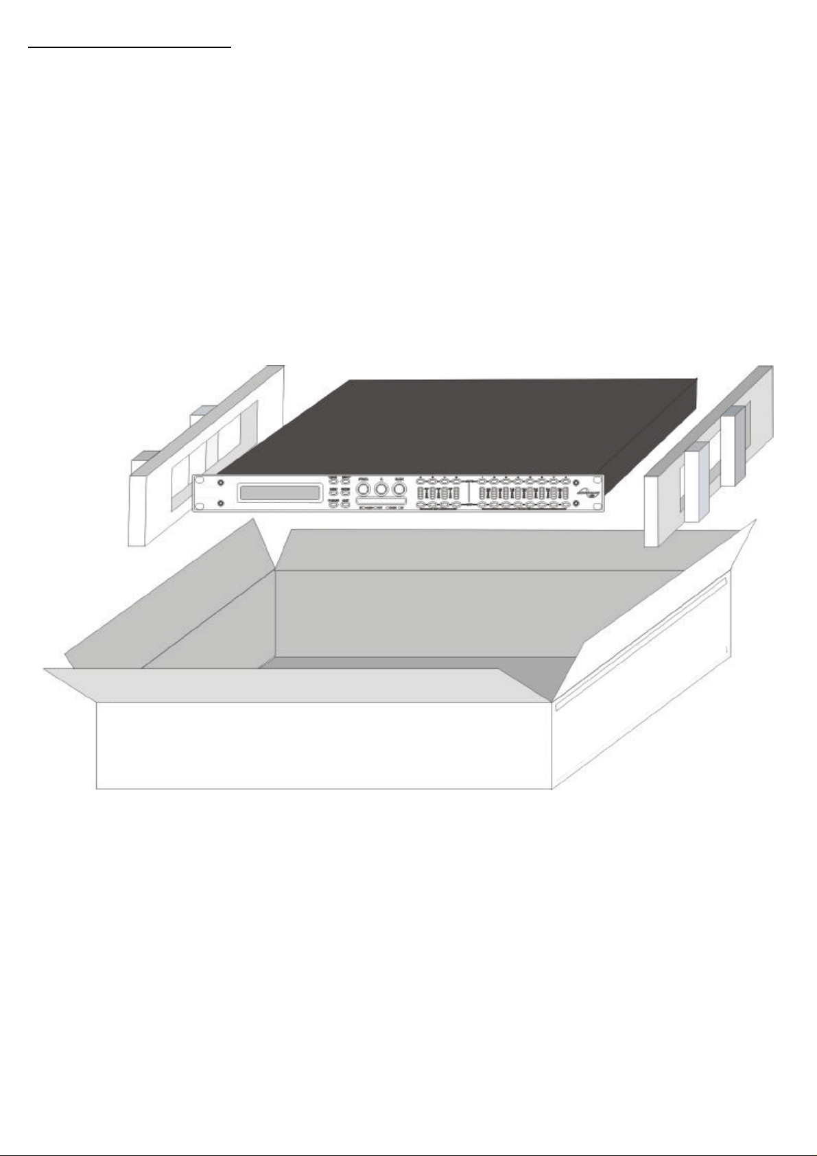
Unpackingtheunit
Afterunpackingtheunit,pleasecheckitcarefullyforanydamage.Ifanyisfound,immediatelynotifythe
5
carrier
concerned-you,theconsignee,mustinstigateanyclaim.Pleaseretainallpackagingincaseoffuturereshipment.
Page 8

Introduction
TheSP27arepowerfulDSPbasedaudioprocessors,ideallysuitedforinstallapplications,wherethey
6
combinethefunctionsofamultitudeofconventionalproductsinacompact1Uunitwithextensiveremote
controlcapabilities.Toachievethis,theunitshaveuptofourinputsandeightoutputswhichcanbeconfigured
inaselectionofbasiccrossovermodes-4x2way;2x3way+2Aux;2x4way;and1x8way(asapplicable
toi/oconfigurations).Theyalsooffera"freeassign"mode,whichallowscompletelyflexibleroutingofany
outputfromanycombinationofinputs.
Eachinputhasagaincontrol,variabledelayandafurthereightbandsoffullyparametricequalisation.The
parametricfilterbandshavealargeselectionofdifferentfiltertypesavailable,includingshelving.
Eachoutputhasagaincontrol,variabledelay,highandlowpasscrossoverfilters,ninebandsoffully
parametricequalisation,polarityswitchingand,additionally,afullyfeaturedlimiter,andafinalcliplimiter.The
crossoverfiltersofferslopesofupto48dB/Octave.,withavarietyofresponsesavailable.
AGPIinterfacemayalsobefittedtoallowremotememoryrecallsusingsimpleswitch closureapparatus.
Securitylock-outisavailableforallcontrols.
TheSP27arealsoequippedwithAES/EBUdigitalinputsandincludeasamplerateconverter,capableof
acceptinganythingfrom32kHzuptp192kHz.
Features
Superbaudioquality-carefullyoptimiseddoubleprecisionsignalprocessingcoupledwith24bitconversion
ensureadynamicrangeinexcessof117dB.Thehighsamplingrateof96kHzmeansminimalfiltering
providingexceptionalsonicpuritywithabandwidthinexcessof32kHz.
Aflexibleinput/outputmulti-modeformatcatersforanyconfiguration,regardlessofscale.
Bothroutingofinputstooutputs,andganging(forediting)arecompletelyflexible.
AcompletelynewSHARCTMbasedDSPplatformsuppliesphenomenalcomputationalpower,allowingthe
unittoprovidenotonlymultiplebandsofstandardparametricequalisationoneveryinputandoutput,butan
additionalfullspectrumgraphicequaliseroneachofthefourinputs.Thisadditionalpoweralsopermitsboth
programlimitersandnoovershootcliplimitersoneachoutput.
Delayofupto650mSmaybeindependentlysetforeachoutput,withanexceptionallyfineminimumincrement
of300nS,whichcorrespondstoadistancechangeof0.1mm!
Thecomprehensivestandardspecificationalsoincludesupto255memories.
XTA'snewproprietaryComplexUnifiedNyquistTruncationalgorithmensuresthatnomatterhowmuch
equalisationisappliedtoachannel,therewillalwaysbesufficientheadroomavailabletocaterforit.
Page 9
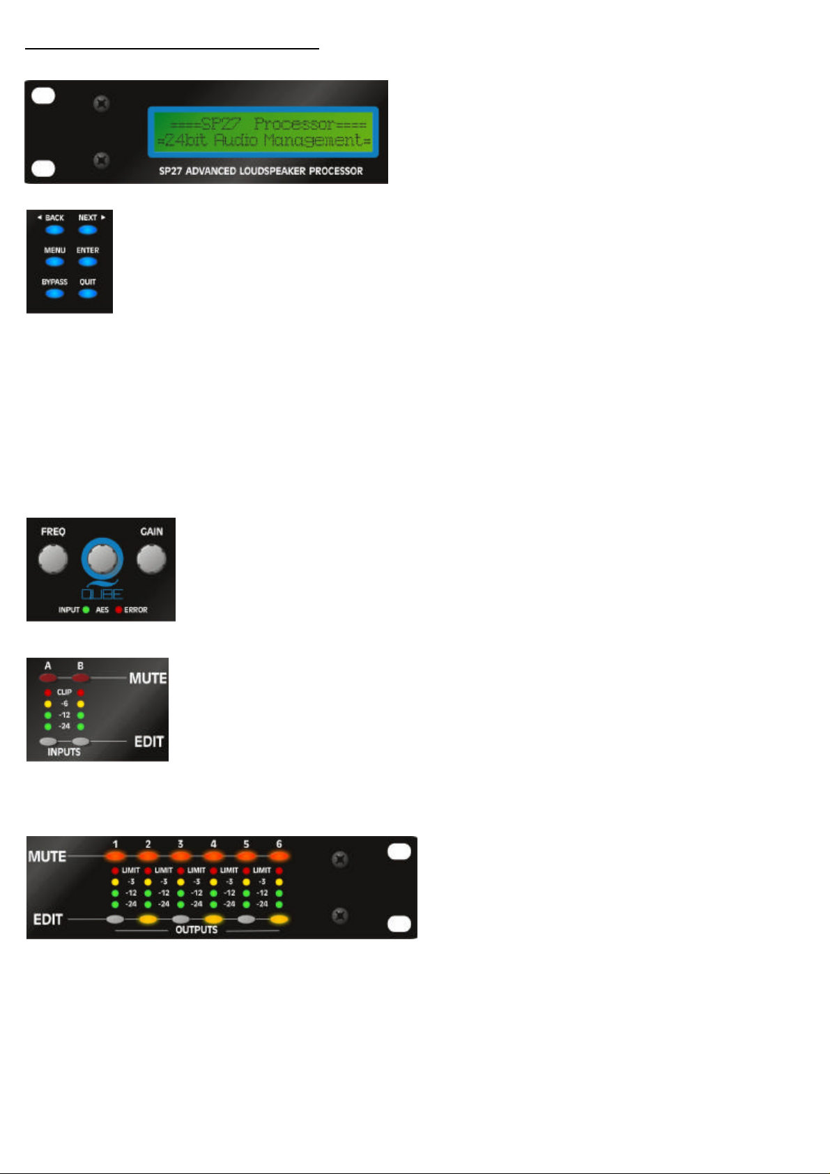
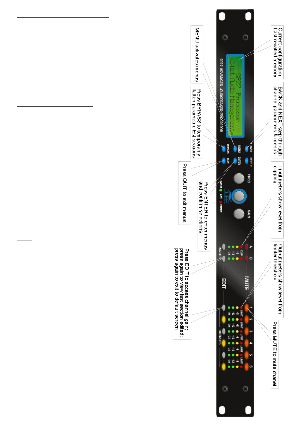
FrontPanelFamiliarisation
7
ControlKeys:
NEXT
BACK
MENU
selectsthelastmenuitem.Inthisway,threepressesonfromthedefaultscreenwill
jumpbacktothelastparameteradjusted.Selectionofdifferentmenusisaccomplishedusing
theandkeys,orwiththeencoder.
BACKNEXTFREQ
ENTER
sections.
BYPASS
tobypassthehighandlowpassfiltersections.
QUIT
keyentersthechosenmenu,confirmsselections,andchangesfiltertypeswheneditingparametric
willflattenthecurrentlyselectedparametricsections.Notethat,forsafetyreasons,itisnotpossible
exitsmenusbacktothedefaultscreen.
keymovesforwardthroughlistofparameters.
keymovesbackwardsthroughlistofparameters.
keyactivatesthemainmenu-asecondpressselectsthelastmenuedited-athirdpress
Selectionandadjustmentofparameters.
LCDScreen:
recalledmemoryonthebottomlineofthescreen,and
thecurrentroutingonthetopline.Alsousedtoshowall
parametersastheyareedited,andallmenuselections.
Shows,bydefault,thenameofthelast
MENU
RotaryEncoders:
displayedonthescreen.
StatusLEDs:
(flashingifnotlocked);
InputSections:
Redbuttonsilluminatewhenpressedandmuteaudioforthatchannel.
MUTE
buttonsilluminateyellowwhenpressed,andaccessgainonfirstpress,thenlast
EDIT
viewedparameteronsecondpress,thenexitonthirdpress.
InputmetersshowdBfromclippingpointoftheanaloguetodigitalconverters.Red
LEDmayilluminateindependentlyfromtherestofthemetertoshowdigital
CLIP
overflow.AlltwoLEDsilluminatingindicatesinternalclippingaftertheADC.
TheredLEDilluminatesattheonsetoflimiting.
Threevelocitysensitiveencodersadjusttherelevantparametersas
ThetwostatusLEDsshow,fromlefttoright,AESinputsselected
Controlandmonitorinputsignalpaths.
CLIP
Error................................
OutputSections:
paths.
Redbuttonsilluminatewhenpressedand
MUTE
muteaudioforthatchannel.
buttonsilluminateyellowwhenpressed,and
EDIT
accessgainonfirstpress,thenlastviewed
parameteronsecondpress,thenexitonthirdpress.
OutputmetersshowdBfromlimiting.
Controlandmonitoroutputsignal
Page 10
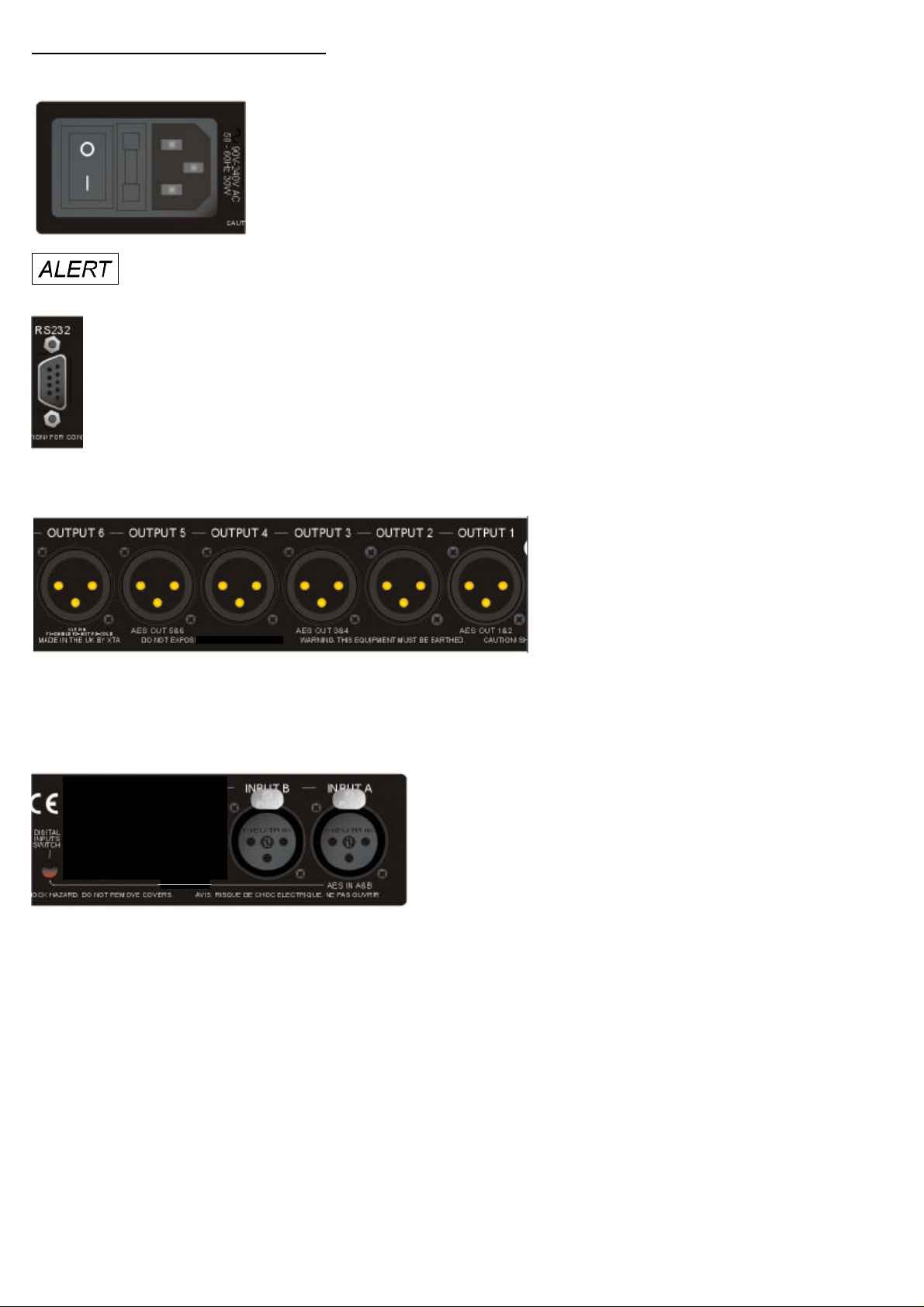
RearPanelConnections
PowerSwitch:
8
MainsFuse:
fuseisalsolocatedinthisholder.
MainsInlet:
Alwaysreplacethefusewiththecorrecttypeandratingasshownontherearpanellegend.
turnstheunit'smainssupplyoffandon.
locatedinafinger-proofholderadjacenttothemainsinlet.Aspare
connectedviaastandardIECsocket.
RS232:
RS485standardandrelayedtoslaveunitsviatheRS485sockets.
RS232standardviaa9pinD-typeconnector,forconnectiontoaPC.Dataisconvertedto
AudioOutputs:
providedforeachchannel.Allarefully
balanced,pin2hot,3cold,1screen.
AESInputSwitch:
inputs.RedLEDwillilluminateintheholewhenAESinputs
areselected,alongwiththecorrespondingfrontpanel
indicator.
AudioInputs:
channel.Allarefullybalanced,pin2hot,3cold,1screen.
RecessedswitchtoselectAESdigital
3pinXLRsocketsareprovidedforeach
3pinXLRsocketsare
Page 11

OperatingtheSP27
NoteaboutoperationwithAudioCoresoftware.
9
ThefollowingoperatinginformationcoverssetupandcontroloftheSP27viathefrontpanelcontrolsonly.
Pleaseconsultthemanualsuppliedwiththissoftwareforinformationregardingfullcomputercontrol.
Start-upprocedure
Switchingontheunitwilldisplayabriefmessagedetailingtheunittypeandsoftwareversionrunning
==AudioCoreDP4XX==
==SoftwareV1.00==
andallLEDswillbrieflyilluminate.Theunitwillthenbeginitscountdowntothewake-upprocedure,during
2
whichtimetheaudiowillfadeuptothelevellastset.Meteringwillbegintooperatewhenthefade-upstarts.
PreliminarySet-up
TheprocedurebelowshouldbefollowedwhenfirstinstallingaSP27unit.
-Designyourcrossover!Todothis,press,andusetheorkeytoselect'
menu'ENTERBACKNEXT'Designacrossover'
ENTERBACKNEXT
andthenpress.Usetheorkeytoselectandthenpress
.Finally,usetheorkeytoselectthedesiredroutingandfollowtheset-upwizardto
MENUBACKNEXTCrossoversub-
3
finaliseyourdesign.
-Notethatwheninamenu,isalwaysusedtoconfirmselections.Thecurrentselectionismarkedwith
ENTER
anasterisk'*'.
-Usethekeysoneachoutputchannelwiththeandkeystoselectthehighpassfilters,low
EDITBACKNEXT
passfilters,parametricsetc.Notethatwhendesigninganewcrossover,thehighandlowpassfilterswillbe
settodefaultvalues.
-Usethekeysoneachinputchannelwiththeandkeystoselectthegain,delayand
EDITBACKNEXT
parametricsavailableoneachinput.
NOTE
2
Thewake-uptimecountdownmaybeadjustedintheSYSTEMmenu-seepage23fordetails.
3
Fordetailsaboutadjustingtheroutingifoneofthestandardconfigurationsdoesnotsuit,seepage15.
Notethatifnoactionistakeninmenumode,theunitwillreturntonormal'default'modeafter
abouttwenty(20)seconds.Repeattheabovedirectionstoreturntomenumode.
Page 12
RoutingOptionsandProcessingBlocks
10
DuetothecompletelynewDSPplatform,theroutingpossibilitieswithinthehavebeenmadecompletely
flexible,withamatrixavailableallowinganycombinationofinputstoberoutedtoanyoutput.Theadditional
DSPpowerhaspermittedtheinclusionofmoreprocessingblocks,evenconsideringtheextrainputsand
outputs,andthedoublingofsamplerate.
Toreduceset-uptimeandaidusability,severalstandardconfigurationsareavailableasdescribedinalater
section.
Thissectionwilloutlinetheprocessingblocksavailableinrelationtothesignalpath,andexplainthevarious
optionsforrouting,includingthe"FreeAssign"mode,whichopensupcompletelyflexiblechannelrouting.
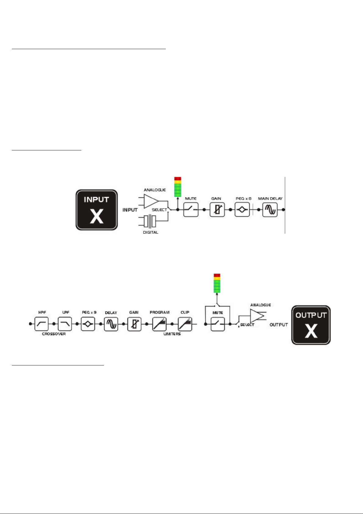
InputChannelMakeup
Thediagrambelowshowstheprocessingavailableoneachofthefourinputchannels,beforeroutingtothe
matrix.
SP27
OutputChannelMakeup
Thediagrambelowshowstheprocessingavailableoneachoftheeightoutputchannels,afterroutingfromthe
matrix.
PresetRoutingConfigurations
Inadditiontotheabilitytoassignanycombinationofinputstoanyoutput,anumberofpresetconfigurations
areprovided,forusewhendesigningacrossoverfromscratch.Thesehavetheadvantageofsuggested
settingsforthehighandlowpassfilterstousefulbasicstartingpoints,tofilterthedifferentoutputsas
appropriateforthechosenconfiguration.Thesemay,ofcourse,befreelymodifiedafterwardsshouldtheynot
suittherequirementsexactly.
Thediagramsonthefollowingpagesshowtheconnectionsmadebetweeninputsandoutputs.
Page 13
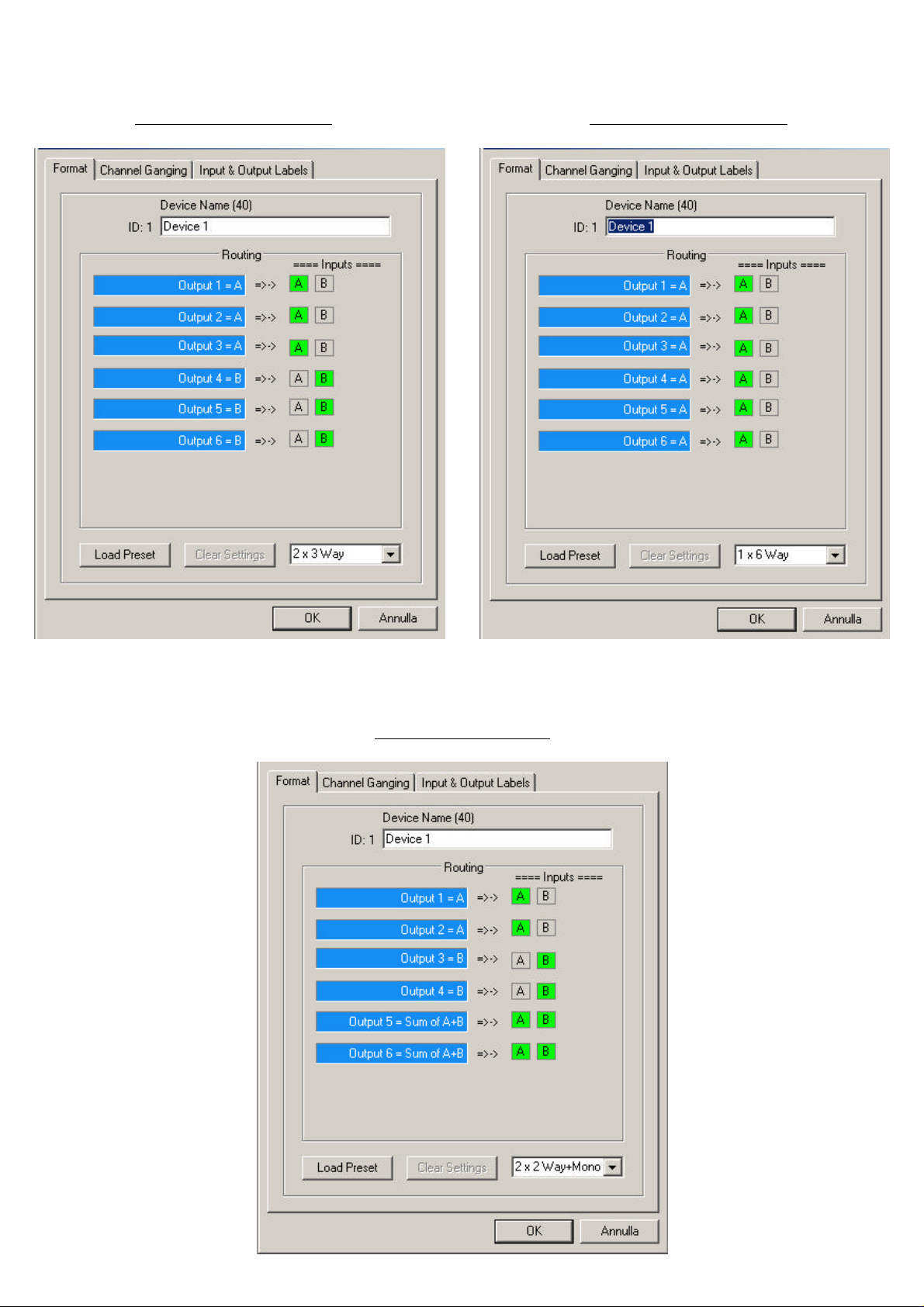
2x3waycrossover 1x6waycrossover
11
2x2way+mono
Page 14
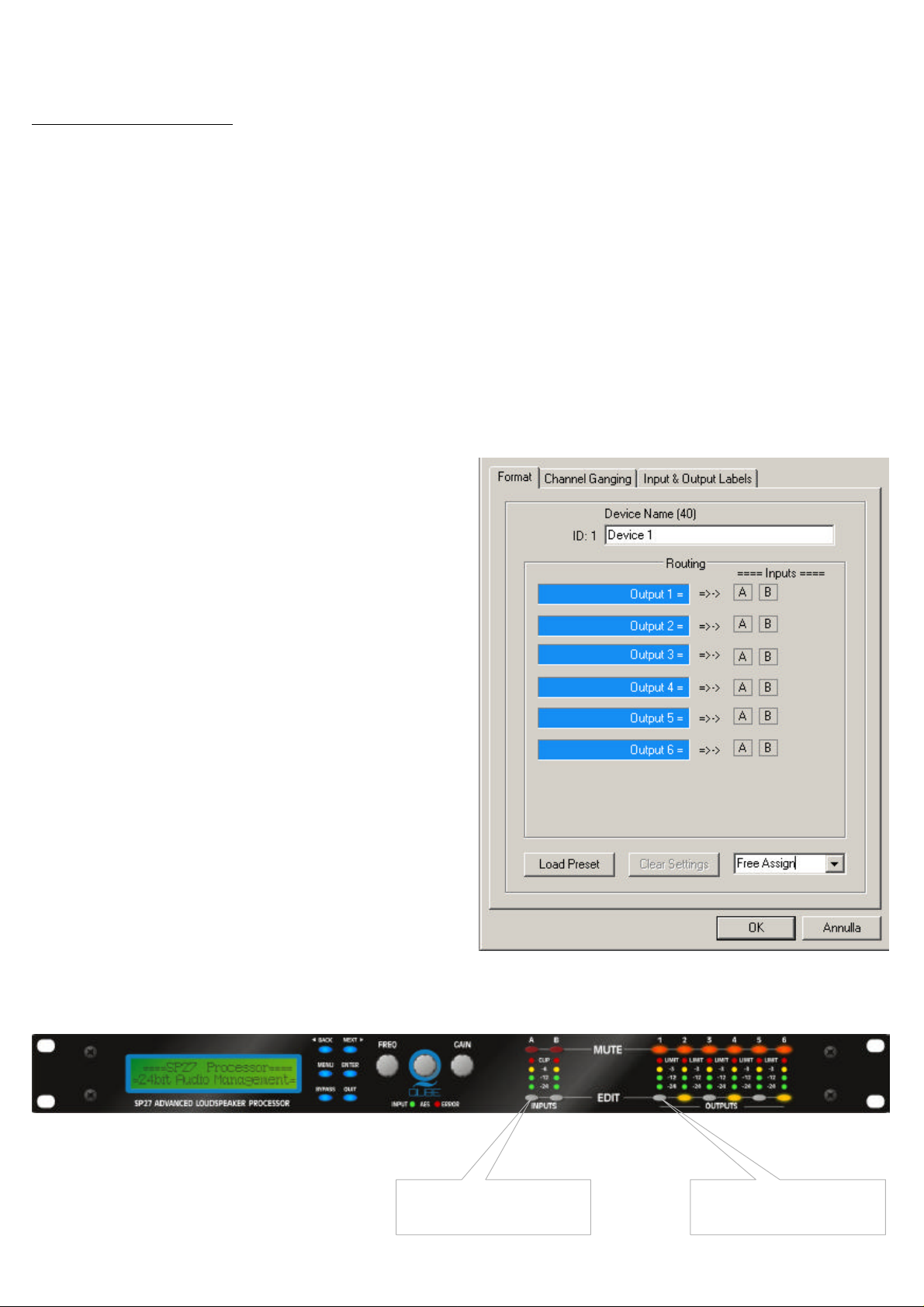
FreeAssignRouting
12
Ifnoneofthepresetconfigurationsareappropriatetotherequiredsystemsetup,itispossibletomanually
selecttheroutingofthecrossover.Thisisachievedthroughthe.
CrossoverMenu->DesignACrossover
Pressingwillstartthecrossoverdesignwizard,withthefirstoptionbeingtochoosetherouting.
Thedisplaywillshow
orwhateverthecurrentconfigurationissetto.Pressuntilthedisplayshows
Andthenpress.Thekeywillilluminate
foroutput1,aswillanyrelevantinputkeys,
showingwhichinputsarefeedingoutput1.Thedisplay
willalsodetailthecurrentcombinationofinputsfeeding
thisoutput.Tochangetheroutingforanyoutput,press
itskey,andthenchoosetherequiredinput
EDIT
channelcombinationbyjustpressingtheinput
keysasappropriate.Theinputcombinationscanalso
besteppedthroughinturnbypressing,or
BACK
Tocompletetheprocedure,press.Thewizard
willcontinue,andiftheroutinghasbeenchanged,all
outputswillbemutedonexit.
.
ENTER
DesignACrossover->
Routing=2X4WAY*
BACK
DesignACrossover->
Routing=FreeAssign
ENTEREDIT
EDIT
EDIT
NEXT
ENTER
2
PressEDITinputkeysto
select/deselectinputs
1
PressEDITtoshowinput
routingselection....
Page 15

EditingAudioParameters-InputChannels
InputGain
13
Therangeofthecontrolovertheinputgainis–40dBto+6dBin0.1dBsteps.
GainInputAInA
InputGain=+6.0dB
Gain
BaseDelay
Themaximumavailabledelaybetweenanyinputandoutputis650.00mS.Forexample,iftheinputdelayon
channelAissetto500mS,themaximumavailableoutputdelayforanyoutputfedfrominputAwillbe150mS.
Thereadoutunitscanbechangedbetweentimeinmilliseconds,distanceinfeetordistanceinmetres.Please
seepageformoredetails.
DelayInputAInA
BaseDelay=0.00mS
x1mS
343mm
x10uS
4mm
InputParametricEQ
Thereareeightbandsofparameterequalisationavailableoneveryinput.Thebehaviourofeachindividual
bandcanbechangedtoavarietyofdifferentfiltershapes,includinghighandlowshelves,notch,and
bandpass.ChangingthefiltertypeisachievedbypressingENTERduringeditinganyparticularband.For
moredetailsaboutthevarioustypesoffilteravailable,pleaseseepage.
PEQ:1<>InputAInA
1k00HzQ=3.00.0dB
Frequency “Q” Gain
Page 16

EditingAudioParameters-OutputChannels
OutputGain
14
Therangeofthecontrolovertheinputgainis–40dBto+15dBin0.1dBsteps.
GainOutput1OP1
OutputGain=+6.0dB
Gain
OutputPolarity
Thepolarity(orphase)ofeachoutputmaybeswitchedindividuallyasbelow.
PolarOutput1OP1
Polarity=[+]
-or+
OutputDelay
Themaximumavailabledelaybetweenanyinputandoutputis650.00mS.Forexample,iftheinputdelayon
channelAissetto500mS,themaximumavailableoutputdelayforanyoutputfedfrominputAwillbe150mS.
Thereadoutunitscanbechangedbetweentimeinmilliseconds,distanceinfeetordistanceinmetres.Please
seepageformoredetails.
DelayOutput1OP1
Delay=0.0000mS
x1mS
343mm
x10uS
4mm
x0.3uS
0.1mm
Page 17

OutputHighPassFilter
15
Thehighpasscrossoverfilteroneachoutputhasafrequencyrangeof<10Hzupto32kHzin1/36Octave
steps.Ifyoutrytosetthehighpassfiltertoahigherfrequencythanthelowpass(whichwouldbepointless
andresultinnooutput),themessageHigh/LowFreq.Overlap!willbedisplayed.Notethattoaccessthe
48dB/Octavefilters,parametricbands6&7needtobebypassed,orsetto0dB.Iftheyarenot,themessage
BypassPEQ's6&7ToAccess48dBSlopeswillbedisplayed.
HPF/--Output1OP1
<10HzLinkw-Riley48dB
th
Frequency
Slope
OutputLowPassFilter
Thelowpasscrossoverfilteroneachoutputhasafrequencyrangeof35.1Hzupto>32kHzin1/36Octave
steps.Ifyoutrytosetthelowpassfiltertoalowerfrequencythanthehighpass(whichwouldbepointless
andresultinnooutput),themessageHigh/LowFreq.Overlap!willbedisplayed.Notethattoaccessthe
48dB/Octavefilters,parametricbands8&9needtobebypassed,orsetto0dB.Iftheyarenot,themessage
BypassPEQ's8&9ToAccess48dBSlopeswillbedisplayed.
Output1OP1
>32kHzLinkw-Riley48dB
LPF--\
SlopeFrequency
th
OutputParametricEQ
Thereareninebandsofparametricequalisationavailableoneveryoutput.Thebehaviourofeachindividual
bandcanbechangedtoavarietyofdifferentfiltershapes,includinghighandlowshelves,notch,and
bandpass.ChangingthefiltertypeisachievedbypressingBYPASStobypassthefilterandthenpressing
ENTERduringeditinganyparticularband.Formoredetailsaboutthevarioustypesoffilteravailable,please
seepage42.
PEQ:1<>Output1OP1
1k00HzQ=3.00.0dB
GainFrequency “Q”
Page 18

OutputLimiter
wizard,intheCrossoverSub-Menu.
16
Thelimiteroneachoutputhasadjustableattackandthreshold,withareleasetimethatisselectabletobea
multiplieroftheattacktime.Forexample,asshownbelow,theattacktimeis2mSandreleaseis“x16”so32mS.
Theattackandreleasetimescanbeautomaticallylinkedtothehighpassfilterfrequency,sothattheyaresetto
correctvaluesfortheoutput'sfrequencyrange.Ifthisfeatureisenabled,thedisplaywillshowAutomaticT/Cin
placeoftheattackandreleasetimes.SelectionofautomatictimeconstantsisthroughtheDesignaCrossover
LimiterOutput1OP1
Atk=2.0mSRel=x16+22dB
Attack
Release
Threshold
Output“D-Max”(Clip)Limiter
Thecliplimiteroneachoutputisdesignedtositatathresholdjustabovethestandardlimiterandhasalook
aheadattacksothatitsthresholdcanneverbeexceeded.Thereleasetimecanbeautomaticallylinkedtothe
highpassfilterfrequency,sothatitissettoavalueappropriatefortheoutput'sfrequencyrange.Ifthisfeature
isenabled,thedisplaywillshowRel.=Autoinplaceofthereleasetime.Selectionofautomatictime
constantsisthroughthe
DesignaCrossoverwizard,intheCrossoverSub-Menu.
Moreinformationaboutthelimitersandtheiruseisgiveninthesectiononpage.
Output1OP1
Rel.=Medium2dBAbove
ClipLim
SlopeFrequency
Page 19

InputGangingandOutputGanging
Themethodoflinkinginputsoroutputstogetherduringeditingisachievedinthesameway,soonlycrossover
17
(output)gangingwillbeexplainedhere.HavingselectedCrossoverGangingfromthemenuunderthe
CrossoverSub-Menu,thecurrentgangingset-upwillbedisplayed.Thiswilleitherbeapresetselectionas
wouldbeusefulinastandardcrossoverconfiguration–forexample
<-CrossoverGanging
Ganging=1+3+5+72+4+6+8
…wouldbealogicalgangingarrangementifthecrossoverwassetupasa–linkingthecontroland
adjustmentofall“Low”outputstogether,andthatofall“High”outputstogether.
However,ifthecrossoverhasnotbeensetupwithapresetroutingconfiguration,thenitmayberequiredto
setupthegangingtocomplimentthisconfiguration.ThisisachievedusingtheFreeAssignmode.Thisis
selectedfromthepresetgangingchoices,whichare:
Ganging=None
Ganging=FreeAssign[chooseganging]
Ganging=1+2+3+4+5+6+7+8[1x8way]
Ganging=1+52+63+74+8[4x2way]
Ganging=1+3+5+72+4+6+8[2x4way]
SelectingFreeAssignandthenpressingENTERwillbegintheprocessofgangingoutputstogetherusingthe
followingsimplerules:
-Alloutputsaregangedtothelowestnumber–sotogangmustbeselectedandthengangedto
-Outputscannotsharemorethanonegangingset–soforexampleoutput
unlesstheyaregangedtogetheraswell.()
Effectively3and4aregangedto2inthiscase
3&5,53.
4x2way
[alloutputsindependent]
3cannotbegangedto2and4
PressMUTEtoselect
1
channeltogang
Withtheserulesinmind,selectingandsettingupgangsisquitestraightforward.
(-CrossoverGanging-)
GangOutput1with1
PressEDITkeystogang
flashingchannelwithselection
2
EDITLEDwilllighttoshowlowestnumberingang
PressaMUTEkeytochoosetheoutputtogang–itsLEDwillbegintoflash,andanEDITkeywillilluminateto
showwhichoutputitiscurrentlygangedwith.Tochangethisselection,justpressanotherEDITkey,
rememberingthatgangsworkfromthehighesttolowestnumber.So,togangoutputs
thenEDIT1
–thedisplaywillshow
<-CrossoverGanging
GangOutput5with1
MUTEbeginstoflash
1and5,pressMUTE5
GangingisclearedbyselectingGanging=Nonefromtheinitialchoicesgivenabove.TheInputGanging
procedureisidenticaltothecrossoverganging,selectableundertheInputSub-Menu.
Page 20

MenuSystemOverview
18
Page 21

MenuSystemShortcuts
Alotoffunctionshavebeenassignedmenushortcuts–theseareaccessibledirectlyfromthedefaultscreen
19
bypressingfollowedbytheappropriateorbuttonasshown.Theentirelistoffeatures
MENUMUTEEDIT
accessibleinthiswayisgivenbelow.
StoreGraphicMemory
StoreInputMemory
StoreCrossoverMemory
StoreGlobalMemory
RecallGraphicMemory
RecallInputMemory
RecallCrossoverMemory
RecallGlobalMemory
SystemStatus
ExternalInterfaceSet-up
ChangeGraphicQ/Bandwidth
FilterQ/Bandwidth DisplayReadout
DelayUnitsTime/DistanceReadout
AESInputStatus
-----
-----
DesignaCrossover
InputGanging
Crossover(Output)Ganging
InputReset
UnitLocking
AESOutputMode
-----
-----
Page 22

MenusinDetail
GLOBALMEM.
20
RecallaMemory
StoreaMemory
EraseaMemory
INPUTSECTION
InputGanging
InputReset
CROSSOVER
DesignaCrossover
CrossoverGanging
INTERFACE
ExternalInterface
Recall,InputandCrossoverMemoriesorcombinationsof.
Store,InputandCrossoverMemoriesorcombinationsof.
Erase,InputandCrossoverMemoriesorcombinationsof.
Gang(link)inputstogethersotheirparameterstrack.
Startwizardtoresetsectionsofinputparameters
Setupanewcrossoverfromscratch.Thisselectionstartsawizardtoguidethroughthe
process.Alsoselectthistoaltertheset-upofthecurrentcrossover.
Gang(link)outputstogethersotheirparameterstrack.
Startsawizardtoconfigurethebaudrate,ID
GPIInterface
SYSTEM
SystemStatus
LCDContrast
LEDBrightness
TemperatureAlarm
Wake-upTime
OutputMetersOpt’n
FilterQ/Bandwidth
DelayTime/Dist’nce
ClipLEDHoldTime
SetDate&Time
ConfiguretheGPIinputsusedforclosedcontactmemoryrecall(hardwareoption).
Displaysaseriesofinformationscreensincludingsoftwareversion,temperature,
hardwareandfirmwareversions,dateandtime.Press NEXT tojumpthroughinfo.
Adjusttheviewingangleofthescreen.
AdjustthebrightnessofallthemetersandbuttonLEDs.
Setthethresholdfortheunittoflashawarningtemperaturemessageonthescreen.
Adjustthetimebeforetheaudiofadesinonstart-up – canalsobeset tokeepmuteson
whenpoweredup.
Selectthemonitoringpointforthemeters – eitherpreorpostmute(someterscanbe
settoworkevenwhenoutputsmuted)
Selectthereadoutunitsforthe‘Q’settingofparametricfilters – ‘Q’is1/Bandwidth(in
octaves)– small‘Q’valuesmeanwideresponsevariations.
Selectthereadoutunitsforalldelayvalues – eithertime,ordistanceinfeetormetres.
SelectthetimethattheinputCLIPLEDs stayilluminatedforafteranoverloadhas
passed.
Adjusttherealtimeclocksettings.
SECURITY
UnitLocking
AES/EBU
AESStatusInfo.
Protecttheunitagainstunauthorisedaccesswithapassword - pleaseseepage 33 for
moredetails.
InformationscreenshowingdetailsoftheincomingAESstreams(samplerate/lock).
Page 23

MemoryStructure
AswiththeSP26,theSP27hasitsmemorysplitintosections,allowingindependentrecallofcrossover
21
settings(i.e.allparametersassociatedwithoutputs),andinputsettings.Additionally,thegraphicequaliser
settingsarestoredinindependentlocations.
Thereare,therefore,threetypesofmemoryavailable–,.
These,andallcombinationsofmemorytypes,appearinthe,andits
operationwarrantsalittlemoreexplanation.
Selectingtoorusingtheoptionoffersthepossibilityofstoringvarious
combinationsoftheavailablememorytypes,andtheseareselectedusingtheandkeys.
Toexplainhowthisallworks,pleaseconsiderthefollowingexample.
Thereare10memoriesstoredintheunitwithvariouscombinationsofinputandcrossovermemories.
StoreRecallGlobalMemory
INPUTCROSSOVER
GLOBALMEMORYSubMenu
BACKNEXT
Ascanbeseen,differentmemorylocationscontaindifferentcombinationsofthethreememorytypes
available.IfitisrequiredtorecallalocationthatcontainsInput,GraphicandCrossoversettings,thiswilllimit
theselectionasshownoverleaf…
Page 24

Therewillbethreememoriestochoosefrominthis
22
case,aslocation6isanInput&Crossovermemory,
whilst8and10willappearastheycontainInputand
Crossoverinformationaswell.
Asonlymemory8andmemory10haveall3types
stored,thesewillbetheonlynumbersavailable
duringarecall.
However,considertheexamplewherethetypeof
recallissettoInput&Crossover.Inthisinstance,
notonlywillthememorylocationsthathavejust
InputandCrossovertypesstoredbeavailable,but
thelocations8&10willalsobeshowninthelist.
SelectionofCrossovermemoriesonlywill
additionallyincludelocations1and6inthelistof
memoriesavailableforrecall,asshownbelow.
Inthiswayitispossibletorecallpartofamemory,
aslongasitcontainsthememorytyperequired.
The4Serieshave256memorylocations,but
thesearedynamicinnature–obviouslya
memorycontainingInput,GraphicandCrossover
settingstakesupmorespacethanonecontaining
justInputsettings.Storageof56memories
containingInput.
Page 25

RemoteControlInterfaceOperation
RS232Interface
23
Thisinterfaceisfittedasstandardtoallunitsandisaccessedviathe9-pinD-typeconnectorontherearofthe
unit.Notethattoconnecttoacomputer'sCOM(serial)portcorrectly,aone-to-onecablemustbeused,and
NOTa'nullmodem'cable.A'nullmodem'cablehasthe'transmit'and'receive'wiresswappedoverandwill
notwork.
TheRS232connectionissuitablefordistancesofaboutamaximumof25feetbetweenthePCandtheunit.If
youexperienceproblemswiththeconnections,consider
·selectingaslowerbaudrate
·selectingthe'UseAcknowledgeCmd'optioninAudioCore(seetheRemoteMenu>RS232
Configurationwindow)
·runningtheunitviatheRS485interface
Notethanonlyoneunitatatimemaybeconnectedtothecomputerviathisinterface.Additionalunitsmaybe
'daisy-chained'viatheRS485connectionsfromthebackofthefirstone(itactingasaconverterforthem),but
theirRS232portsarenotused.
RS232Connection(SingleUnit)
Atypicalinterfaceset-upmightinvolverunninganRS232linkfromlaptoporadesktopcomputertoaSP27
unitsetupasamasterunit.Thediagrambelowshowsthismethodofconnection,therequiredmenuoptions
arealsogiven.NotethattheRS232cablemustbea1-1connectiontype,NOTanullmodemcable(which
hasconnectionscrossedinternally).
LoadingNewSoftwareviaaPC
Theunit'sinternalsoftwaremaybeupdatedviatheRS232port,oneunitatatime.Werecommend
disconnectingallotherdeviceswhenupdatingthesoftware.
Theunit'sinterfacemustbesetasRS232MasteronID1forthePCloaderprogramtorecogniseitandallow
theupdatetobesent.
Downloadthelatestversionoftheloaderprogramandtheunitsoftwareandfollowtheinstructionsincluded
withthiszipfile.AnRSSfeedisavailableonthewebsitetoensureimmediatenotificationofsoftware
releases.
ONLY
Page 26

AESInputs
TheSP27SeriesunitshaveafullAESimplementationbuiltinasstandard.Thisallowstheunittoreceive
24
digitalaudiodirectly.Theswitchingofinputcanbeperformedindependently,andtheinclusionofsamplerate
convertersontheinputsallowstheunittoacceptsampleratesfrom32kHzupto192kHz.
AESInput
Inputselectionisviaarecessedswitchontherear
paneloftheunit,betweeninputBandoutput1.A
redLEDinsidethisapertureilluminatestoshowthat
theAESdigitalinputshavebeenselected.
AcomplimentaryLEDonthefrontpanelalso
illuminates.TheswitchcontrolstherearpanelLED
directly,whilstthefrontpaneloneisviatheprocessor,
allowingittorelayalittlemoreinformation.
Ifitisflashing,thismeansthatAESinputshave
beenselectedbuthavenotlocked.Onceastable
AESsignalisbeingreceived,itwillbepermanently
illuminated.
TheAESinputsaremarkedontherearpanel–
forchannelAuseinputA,
andforchannelBuseinputB.
Page 27

AESDiagnosticsandStatusInformation
AlsoundertheAES/EBUSubMenuistheAESStatusInformationoption,whichcanbeusedtocheckthe
25
incomingsamplerate(s)andconfirmthatthedataisbeingreceivedcorrectly.
Pressingwillfirstshow
ThisdisplayshowsthecorrectoperationoftheAEStransmittersV1,V2.Theletteraftereachisthesilicon
version(andisofnoimportancetotheuser).
Pressingagainwillshow
ThisdisplayshowsthestatusofthetwoAESreceivers,inputAontheleft,andInputBontheright.The
sampleratetheunithasbeenabletolocktoisshown,orUNLOCKEDwillbedisplayedinitsplace.Theunit
willlocktosampleratesfrom32kHzuptoandincluding192kHz.
Theunit'sownprocessingsamplerateis96kHz,andAESoutputdataisalwaysat96kHz.Internalsample
rateconverterswilltranslateallincomingratesto96kHz–oneconverterforeachAESinput.Thisallowsthe
twoinputstreamstobeatdifferentratesifnecessary.
ENTER
AESDeviceStatus
V1:EV2:E
ENTER
AESDeviceStatus
V:96k0V:96k0
Page 28

SecurityandLocking
AfterselectingtheSecuritySubMenuandpressing,selectoneofthelocktypes,choosingthemost
26
appropriateoneforyourapplication.Asever,willconfirmyourselection.
UserSpecific
Uponpressingtoselectthistypeoflock,eachparametergroupispresentedinturn.Choosethetype
oflock(asabove)usingtheencoder,andpresstoconfirmeachparameter.Afterthelast
parameter,theunitrequestsapassword.Thedescriptionofthisoperationisgivenattheendofthissection.
Thisoptionallowstheusertospecify,foreachtypeofparameter,whetheritistobecompletelyaccessible
('NoLock'),viewablebutnotadjustable('Control'),oreffectivelyunavailable('Display').Theabilitytooperate
mutes,storeorrecallmemories,orevenaccessthemenusmayalsobelocked.
XoverOnly
Allinputparametersareavailable,butonlythegaintrim(6dB)isavailableontheoutputs,effectivelylocking
allthecrossoversettings.Allmutesremainactive.
Xover+Trim
Allinputparametersavailable,butnooutputparameters–thecrossoversectionsarecompletelylocked.All
mutesremainactive.
Xover+Trim+Mute
Asfor'Xover+Trim'butadditionally,outputmutesarelocked.Inputmutesremainactive.
ChangesOnly
Allparametersmaybeviewed,butnonemaybeadjusted.Thisappliestobothinputsandoutputs.Allmutes
remainactive.
Changes+Views
Noparametersareaccessible–ineffectthekeysdonothing.Allmutesremainactive.
Changes+Mutes
Allparametersmaybeviewed,butnonemaybeadjusted.Thisappliestobothinputsandoutputs.Allmutes
arealsolocked.
EVERYTHING
Noparametersareaccessible–ineffecttheandkeysdonothing.
ENTER
FREQENTER
ENTER
EDIT
EDITMUTE
ENTER
+
EnteringthePasswordtoCompletetheLockingOperation
Afterselectionofthelocktypefromthelistabove,afour-digitsecuritycodewillbeaskedfor.Thiscanbe
enteredbyusingthecontroltoselectacharacter,andtheandkeystomovetothenext
character.
Alternatively, thekeyscanbeusedtoenteracodebypressinganycombinationofthesixbuttons.Each
keyrepresentsitschannellabelling,soanycombinationof,canbeusedasacode,
EDITA,B,1,2,3,4,5,6
asshownbelow.Presstoacceptcodeandthenre-enterittoconfirm.
FREQBACKNEXT
EDIT
ENTER
A B 1 2 3 4 5 6
HINT
Topreventexternalcomputercontrolbeingusedtoadjustlockedsettings,besuretoset
theexternalinterfacetoOFFbeforelockingouttheunit.
Page 29

UnlockingtheUnit
27
Tounlocktheunitpressandthentypethecodein.Thiscanbeenteredbyusingthecontrolto
selectacharacter,andtheandkeystomovetothenextcharacter.Alternatively,thekeys
canbeusedtoenteracodebypressinganycombinationoftheeightbuttons.Eachkeyrepresentsits
channellabelling,asdescribedinthelockingsection.
ForgottenthePassword?
Don'tpanic!Yourunitcanstillbeunlocked.InanattempttoimprovethesecuritysystemontheSP27,and
preventastandardmasterpasswordfrombecomingcommonknowledge,theunitsnowhavearandom
passwordkeygenerator.
Theprocedureforunlockingaunitusingthepasswordoverrideisexplainedbelow:
Switchtheunitonwiththekeyheldinmomentarily.Afterafewseconds,theunitwillaskforasecurity
code.Usethekeysinthesamemannerasforenteringlockcodes(seepagefordetails)andenter
2121.
Thedisplaywillshow:
TheBreakCode(intheexample12345)shouldbenotedandsupplied.Wehavesoftwaretogeneratethe
correspondingPassCodewhichshouldbetypedin,followedby.Thiswillunlocktheunitandwipe
thepreviouspassword.
EDIT
ENTERFREQ
BACKNEXTEDIT
EDIT
MENU
EnterSuppliedCode:
BreakCode=12345[NNNN]
ENTER
Notethefollowingaboutthisprocedure:
OncetheBreakCodehasbeennoted,doNOTpressagainduringtheoperationoftheunit(exceptto
getbacktothispointonpowerup),oradifferentcodewillbegenerated.Theunitmaybeusedasnormal,but
everypressofwillchangetheBreakCode,sothePassCodesupplywillnotwork!
Theunitmaybeswitchedonandoffasnecessary–justbesureNOTtopress,ortheentireBreak
Codeprocedurewillhavetoberepeated.
MENU
MENU
MENU
Page 30

28
ADVANCEDAUDIOFEATURES
ProgramLimiterand“D-Max”Limiter
TheSP27unitshavetwolevelsofdynamicprotectiononitsoutputs–atraditionalprogramlimiter,anda
newlyintroduced“D-Max”limiter.
ProgramLimiter
Highperformancedigitallimitersareprovidedforeachoutputwithcontroloverattacktime,releasetimeand
thresholdparameters-seepagefordetails.Thislevelofcontrolallowstheusertobalancetherequired
subjectivequalityofthelimiteragainstthedriverprotectionrequirements.Itdoesalsomeanthatan
incorrectlysetlimitermaysoundawful!Inparticular,aswithalllimiters,usingtoofastanattackorreleasetime
willresultin excessivelowfrequencydistortion.Inthesub-menuthereisanoptionforautomatic
limitertimeconstants.Usethisoptionifyouareunsurehowtosetthetimeconstantsmanually.Itis
recommendedtheuseoftheautomaticsetting.
InthismodethetimeconstantswillbeautomaticallysetfromtheHigh-Passfilterfrequencyaccordingtothe
tablebelow.
Thetimeconstantsaresetbythehighpassfilterfrequencyforthatchannel.
DesignaCrossover
HighPassFilter AutoAttackTime ReleaseTime
<10Hz – 31Hz 45mS x16(720mS)
31Hz – 63Hz 16mS x16(256mS)
63Hz – 125Hz 8mS x16(128mS)
125Hz– 250Hz 4mS x16(64mS)
250Hz– 500Hz 2mS x16(32mS)
500Hz - 1kHz 1mS x16(16mS)
1kHz – 2kHz 0.5mS x16(8mS)
2kHz – 32kHz 0.3mS x16(4mS)
Page 31

“D-Max”ClipLimiter
29
Themainlimitationwithtraditionaldynamicscontrolistheinabilityoftheprocessingtoreacttruly
instantaneouslytothesignal.Oneofthemostsignificantadvantagesofdigitalsignalprocessingover
analogueistheabilitytodelaytheaudiosignalpreciselyandwithoutextensivecomplexhardware.Theentire
domainofdigitalsignalprocessingisbasedaroundthecombinationofdelaying,multiplying,andaccumulating
numbers(representingsamplesofaudio)toimplementallthefiltersanddynamicsprocessingwehavecome
toexpecttoday.
Inthecaseofdynamicsprocessing,beingabletodelayasignalallowstheprocessormoduletodelaythe
mainsignalinrelationtothesidechain(thesignalbeingmonitoredrelativetothethreshold),sothatitcan
compensateforpeakspriortothearrivalofthemainsignal.
Considerthesituationofamonitorengineerlisteningtoabandperform.Havingnoaccesstodynamics
processors,hehashadtoresorttomanually'ridingthefaders'inanattempttokeepcontrolofthelevels.
Shouldthelevelofoneofthechannelsonhisdeskreachanunacceptablyhighlevel,hewillturnitdown
appropriately.
Thereisahiddensidechaininoperation
eveninthiscase.Themainsignalpathis
fedthroughthemonitordeskandthegain
controlledbyadjustingthefader.The
sidechainisformedbythefeedbackpath
betweentheengineer'searscheckingthe
levelandhisbraininstructinghishandto
turnthefaderdownifthevolumegoesover
thethresholdhehaschosen.
Inthiscase,thedelaybetweenthesignalactuallygoingoverthethreshold,theengineerregisteringthe
situation,andthenturningthesignaldownwillbeintheorderofseveralhundredmillisecondsatbest.This
willonlybetrueifheisnotdistracted–inreality,itmaybeseveralsecondsbeforeanygainreductionis
imposedonthesignaltobringitundercontrol.
Forananaloguedynamicsprocessor,thesituation
ismuchbetter.Controllingthegainelectronically,
andnotrelyingonahumansidechainfeedback
mechanism,itcanreactmuchmorequickly.
Theredwaveformrepresentstheinputtothe
dynamicsmodule,withthedottedlineshowingthe
thresholdforgaincontroltooccur.Thereare
severalpeakstowardsthestartofthissignalthat
areabovethethreshold,andsothedynamics
processingshouldreacttotheseasappropriate.(In
thiscasereducethegain).
Thebluewaveformshowstheoutputofthe
dynamicsmodule.Thecircledpeakdemonstrates
thattheprocessorhasmissedthefirstpeakabove
thethreshold(asitisveryfastandshort),buthas
'caughtup'shortlyafterwards,keepingallother
peaksundercontrol.Asitisunabletopredictwhat
iscoming,thiswillalwaysbeafailingwithanalogue
dynamicsprocessing.
Page 32

TheSP27“D-Max”limiterpredelaysthesidechainsignal,resultingina“zeroovershoot”limiter,whichisable
30
tocatchallpeaksandprovideareliableabsolutemaximumsettingfortheoutputofanychannel.
Thepredelayedsidechainisshowningreen,with
themainsignalinred.Asthemainsignalarrives
slightlyafterthesidechain,theoutputfromtheunit
doesnotsufferfromtheovershootproblem.
Rememberthatthisdelayisonlyintheorderof
tensofuS,andisa–thesidechainis
movedintimeinrelationtothemainsignal.
back
Insertingadelayintothesignalpathofan
predelay
main
analoguedynamicsprocessorwillachievesimilar
results,butwiththepenaltyofdelayingthemain
signalbytheamountoflookaheaddelay
introduced.
The“D-Max”limiterwhichappearsinoutputlistsjustfollowingthetraditionallimiter,hasonlytwoparameters
toadjust:
OP1Output1ClipLim
Rel.=Medium10dBAbove
Thereleasetime(eitherFast,Medium,orSlow)andthethreshold.Notethatthethresholdissettobea
minimumof2dBabovethethresholdoftheprogramlimiter–settingthethresholdto10dBAbove,asinthe
example,meansthatnomorethan10dBofovershootabovethethresholdoftheprogramlimiterwilleverbe
allowed.
ThereleasetimemayalsobesettofollowtheHighPassfilteroftheoutput–thisisachievedthroughthe
Crossover
sub-menu,andwillresultinthedisplaychangingtoshow
Designa
OP1Output1ClipLim
Rel.=Auto10dBAbove
Page 33

SettingAccurateLimiterThresholds
31
ThelimitersbuiltintotheSP27Seriesareintendedtobeusedforloudspeakerdriverprotection,asopposedto
amplifierprotection.Allmodernprofessionalpoweramplifiersdesignedforlivesoundusehavetheirown
limiters,whicharetailoredtoprotectingtheamplifierfromclipping.
Thefollowingsectiondescribeshowtosetuptheunits'limiterstoprovideexceptionalprotectionagainstdriver
overheating,andconeover-excursion.
MostspeakersystemsaregivenapowerratinginWattsRMS.Thisisthemaximumcontinuouspowerthat
thesystemwillhandleandoftenappearsveryconservative.Inreality,asmusicprogramisfarfrom
continuousinnature,thepeakpowerofthesystemismuchhigher–uptotentimesthecontinuousfigure.
Anylimiter,whichistoprotectthedriverfromdamage,mustbeabletofulfilthefollowingtasks.
·HaveanattacktimewhichiscalculatedtoallowtransientsthroughbutkeeptheRMSlevelbelowthe
speakermanufacturersspecification;
·Haveareleasetimewhichissufficientlylongtoavoidthelimiteritselfmodulatingtheprogram;
·Beintelligentenoughtoadjusttheenvelopeofthelimiteraccordingtothefrequencycontent ofthe
programmaterial.
Theprogramlimitersarecapableofperformingallthesetasks.Theonlyparameterthattheusermustset
manuallyisthethreshold,anditiscrucialthatthisisdonecorrectly.Considerthetablebelow.
dB Ratio Vrms
45 177.83 137.74 2371.71 4743.42 9486.83
44 158.49 122.77 1883.91 3767.83 7535.66
43 141.25 109.41 1496.45 2992.89 5985.79
42 125.89 97.52 1188.67 2377.34 4754.68
41 112.20 86.91 944.19 1888.39 3776.78
40 100.00 77.46 750.00 1500.00 3000.00
39 89.13 69.04 595.75 1191.49 2382.98
38 79.43 61.53 473.22 946.44 1892.87
37 70.79 54.84 375.89 751.78 1503.56
36 63.10 48.87 298.58 597.16 1194.32
35 56.23 43.56 237.17 474.34 948.68
34 50.12 38.82 188.39 376.78 753.57
33 44.67 34.60 149.64 299.29 598.58
32 39.81 30.84 118.87 237.73 475.47
31 35.48 27.48 94.42 188.84 377.68
30 31.62 24.49 75.00 150.00 300.00
Usingthistableitisastraightforwardproceduretoworkouttherequiredsettingofthelimiterthresholdsforthe
system.
Pwr8 Ω Pwr4 Ω Pwr2 Ω
“First,checktheRMSpowerratingofthespeakersystem,anditsimpedance.
“Lookupthisvalueinthetableabove,usingtheclosestvaluebelowtheratedpowerofthespeaker
system.Notethecorresponding'dB'value.
”Checkthegainofyouramplifier,whichneedstobein'dB'.
”SubtractFROMthisgainfigurethatobtainedfromthetabletofindtherequiredabsolutesettingforthe
limiterthresholds.
Notethat,forsafety,alwayssetthelimiterthreshold1or2dBbelowthemaximumallowableworkedoutusing
theabovemethod.
ALERT
ALWAYSREFERTOYOURSPEAKERMANUFACTURERFORLIMITERSETTINGS.
Page 34

CrossoverFilterSlopes
Itshouldalsobenotedthattheturnoverfrequencydisplayedonthescreenisthe-3dBpointforalltypes
exceptLinkwitz-Rileywherethe-6dBpointisshown.Ifthe-6dBpointistobeusedfortheBesselor
Butterworthfilter,taketherequiredcrossoverfrequency,multiplythisbytheappropriatefactorfromthe
followingtableandthenselecttheclosestavailablefrequencyonthedisplay.
FilterType Highpassfactors Lowpassfactors
Bessel12dB/Oct. 1.45 0.69
Butterworth12dB/Oct. 1.31 0.76
Bessel18dB/Oct. 1.37 0.73
Butterworth18dB/Oct. 1.19 0.84
Bessel24dB/Oct. 1.35 0.74
Butterworth24dB/Oct. 1.15 0.87
Bessel48dB/Oct. 1.39 0.72
Butterworth48dB/Oct. 1.08 0.93
Pleasenotethatunlikeconventionalanaloguecrossovers,crossoverpointsandslopesaresetwithabsolute
accuracysincecomponenttoleranceproblemsdonotoccur.
Pleaseseepagefordetailsofhowtoadjustthehighandlowpasscrossoverfiltersettings.
TimeAlignment
AfurtheradvantageoftheSP27Seriesoverconventionalproductsistheprovisionofanindependently
adjustabledelaysectionforeachoutput.Thisallowsthetruearrivaltimefrommultipledriverstoprecisely
alignedratherthanrelyingonthecompromise'phaseadjust'approach.Delaytimeisadjustablein03Ssteps
(0.1mm).
Pleaseseepagefordetailsofhowtoadjustthedelaytimes.
Toconvertfromunitsoftime(i.e.milliseconds)tounitsofdistanceusethefollowingformula:
1millisecond=343mm(1.126ft)@20C(68F)
Tocalculatetimedelayforaknowndistance,use:
Timedelay=
Distanceinmeters
20.06x273+C
whereCisthetemperatureinC.
.
Tosimplifythisequationat20C.
Delaytimeinmilliseconds=
(Distanceinmetersx2.192)or(Distanceinfeetx0.955)
Note:Centigrade=(Fahrenheit–32)x0.5555.
32
Page 35

ParametricFilterTypesandTheirUses
33
AwideselectionoffiltertypeshasbeenmadeavailableunderthePEQsectionwheneditinginputoroutput
filters.ScrollingthroughthevariousfiltertypesisachievedbyrepeatedpressesoftheENTERkey.Notethat
thiswillonlychangefiltertypesifthefilterisBYPASSEDortheGAINsetto0dB.Bypassingthefilter,then
changingtypesusingtheENTERkeywillautomaticallysetthegainbackto0dB.
Eachfiltertypewillbeexplainedinturninthefollowingsection.
StandardParametricEQ
InAInputAPEQ:1<>
1k00HzQ=3.00.0dB
Thestandardparametricbandhasadjustable
frequency,'Q'(orBandwidth)andGaincontrols.
Theseaffectarangeoffrequenciessymmetrically
aboutthecentrefreqencyasshowninthegraph.
Variouslevelsofcutandboostareshowntotheleft,
alongwithvarious'Q'settings(gainboostsonlyare
shownbelow).Rememberthat'Q'is1/Bandwidth,
sothehigherthe'Q',thelowertheBandwidth,and
thesmallertherangeoffrequenciesaffected.
Page 36

ShelvingEQ(HighShelfshown)
Rememberthat'Q'is1/Bandwidth,sothehigher
34
the'Q',thelowertheBandwidth,andthesmallerthe
rangeoffrequenciesaffected.
InAInputAHSF:1-<::
1k00HzQ=3.00.0dB
Remember–tochangefiltertypes,pressBYPASS
tobypassthefilter,andthenuseENTERtoselect
thefiltertype.
TheshelvingEQhasadjustablefrequency,'Q'(or
Bandwidth)andGaincontrols.Theseaffectarange
offrequenciesfromtheturnoverfreqencyasshown
inthegraph.Forahighshelf,frequenciesabove
theturnoverfrequencywillbeaffected.Foralow
shelf,frequenciesbelowtheturnoverfrequencywill
beaffected.
Variouslevelsofcutandboostareshowntotheleft,
alongwithvarious'Q'settings(gainboostsonlyare
showbelow).
Notethat'Q'settingsabove0.75willresultinslight
overshootinthefilterresponse(asseenatthe
highestsettingtotheright).Thisisnormal
behaviouranddoesnotindicateinstability.
CreatingaFlat-toppedEQResponse
Tocreateaflat-toppedEQfilterresponsesuchas
thatshowntotheleft,usetwoEQbands,BOTH
configuredaslowshelves.ForanoverallBOOST,
settheLowerfrequencyfiltertoBOOSTthedesired
amount,andtheUpperfrequencyfiltertoCUTby
thesameamount.
Thisexampleshowsonefilterat100Hzandthe
otherat2kHz,withthe100Hzfilterat–10dB,and
the2kHzfilterat+10dB.Varyingthe'Q'affectsthe
slopeoftheresponse–valuesabove0.75will
causeovershootasshown.
Assymetricalresponsesmaybeachievedby
adjustingthe'Q'ofeachfilterindependantly.
Page 37

Low/HighPassVariable'Q'Filter(LowPassshown)
35
InAInputALPF:1~~\
1k00HzQ=3.0LPFVarQ
Remember–tochangefiltertypes,pressto
bypassthefilter,andthenusetoselectthefilter
type.
Thelowandhighpassvariable'Q'filtershave
adjustablefrequencyand'Q'(orBandwidth)controls.
The'Q'controladjustthedampingofthefilter,sothat
low'Q'settingsshowlessovershootattheturnover
frequency,butalsoslowerroll-off.
Rememberthat'Q'is1/Bandwidth,sothehigherthe'Q',
thelowertheBandwidth,andthesmallertherangeof
frequenciesaffected.Thefilterisprimarily12dB/Octave,
butinachievingthissortofroll-offwithahigh'Q'valuewillresultinquitealargeovershootinlevelatthe
turnoverfrequency.Thistypeoffilterisoftenalsocalledaresonantfilter.
ENTER
BYPASS
Page 38

Specifications
Inputs:
36
2/4electronicallybalanced
Impedance:>10kohms.
CMRR:>65dB50Hz-10kHz.
Outputs
:4/6/8electronicallybalanced
SourceImp:<60ohms
Min.Load:600ohm
Max.Level:+20dBminto600ohm
Limiters
ProgramLimiter:
Threshold:+22dButo-10dBu
Attacktime:0.3to90milliseconds
Releasetime:2/4/8/16/32xAttacktime
“D-Max”Limiter:
AttackTime:-60uS
ReleaseTime:Slow/Medium/Fast
FrequencyResp
.:½dB20Hz-20kHz
+
-3dB@32kHz
Dyn.Range
Distortion:
:>116dB20Hz-20kunwtd
<.02%@1kHz,+18dBm
MaximumDelay:650mS
MinStepSize:03S
InputGain:
OutputGain
.
+6dBto-40dBin0.1dBsteps
:+15dBto-40dBin0.1dBstepsand
mute
ParametricEqualisation
8perInput/9SectionsperOutput
FilterGain:+15dBto-30dBin0.1dBsteps.
Freq.Range:19.7Hz-32kHz,1/36octavesteps.
FilterQ/BW:0.4to128/2.5to0.008
(Sectionsswitchedtoshelvingresponse)
Lowfrequency:19.2Hz-1kHz
Highfrequency:1kHz-32kHz
Shelfgains:15dBin0.1dBsteps.
HighandLowpassFilters
Filters:1ofeachperoutput.
Freq.RangeHPF:10Hz-16kHz
1/36octavesteps.
Freq.RangeLPF:35Hz-22kHz
1/36octavesteps.
Responses:
st
1Order6dB/Oct.
Bessel/Butterworth/Linkwitz-Riley12-24-48dB/Oct.
Bessel/Butterworth18dB/Oct.
Display:
Inputmeter:
Outputmeter:
2x24CharacterLCD
2x6point,-24dBtodigitalclip.
8x6point,-24dBto+4dBintolimit.
Connectors
Inputs:3pinfemaleXLR
Outputs:3pinmaleXLR.
External:9pinDEEconnector(RS232)
Power:3pinIEC
Power:
Consumption:
Weight:
Size
60to250V15%@50/60Hz.
<30watts.
3.3kg.Net(4.7kg.Shipping)
:1.75"(1U)x19"x11.8"
(44x482x300mm)excludingconnectors
Transformeroptionsavailable
Duetocontinuingproductimprovementtheabove
specificationsaresubjecttochange.
Latency:
1.5mS(analoguein–analogueout@96kHz)
Page 39

Index
37
A
G
AESDiagnostics
AESInterface
AESMenu
AttackTimes
B
BaseDelay
C
ClipLimiter
CrossoverMenu
D
Delay
LookAhead
DigitalIn&Out
D-Max
E
Editing
BaseDelay
HighPassFilter
InputGain
Limiters
LowPassFilter
OutputDelay
OutputGain
ParametricEQ
Polarity
F
Features
FlatToppedEQ
FreeAssign
FrontPanel
25
24
20
28
13
16,29
20
13
29
24
29
13
15
13
16
15
14
14
13,15
14
6
34
12
7
GangingInputs
GangingOutputs
GlobalMemoryMenu
GraphicMenu
H
HighPassFilter
I
InputGain
InputSectionMenu
Interface
RS232
USB
InterfaceMenu
L
Limiter
OvershootPrevention
LimiterThreshold
Limiters
LoadNewSoftware
Lockouts
LookAhead
LookAheadDelay
LowPassFilter
M
MasterPassword
MemoryStructure
Menus
Details
QuickRef.
Shortcuts
17
17
20
20
15
13
20
23
23
20
30
31
28
23
26
29
29
15
27
21
20
18
19
Page 40

38
O
S
OutputDelay
OutputGain
P
ParametricEQ
PasswordOverride
Passwords
Polarity
ProgramLimiter
Q
QuickSetup
R
RearPanel
ReleaseTimes
ResonantFilter
Routing
Basic
FreeAssign
Presets
RS232Interface
14
14
13,15
27
26
14
16
9
8
28
35
12
10
12
10
23
Security
SecurityMenu
ShelvingEQ
Shipping
Sidechain
Delay
Specifications
StandardParametric
Start-up
SystemMenu
U
Unlocking
Unpacking
USBInterface
V
Vari-Q
26
20
34
5
29
36
33
9
20
27
5
23
35
Page 41

AppendixI–SP27DefaultCrossoverConfigurations
2x3Way
39
Page 42

2x2Way+MonoSum
+
+
40
Page 43

1x6Way
41
Page 44

Allinformationincludedinthisoperatingmanualhavebeenscrupulouslycontrolled;howeverFBTisnot
responsibleforeventualmistakes.FBTElettronicaS.p.A.hastherighttoamendproductsandspecifications
withoutnotice.
 Loading...