

Page 1
shapingthesoundoftomorrow
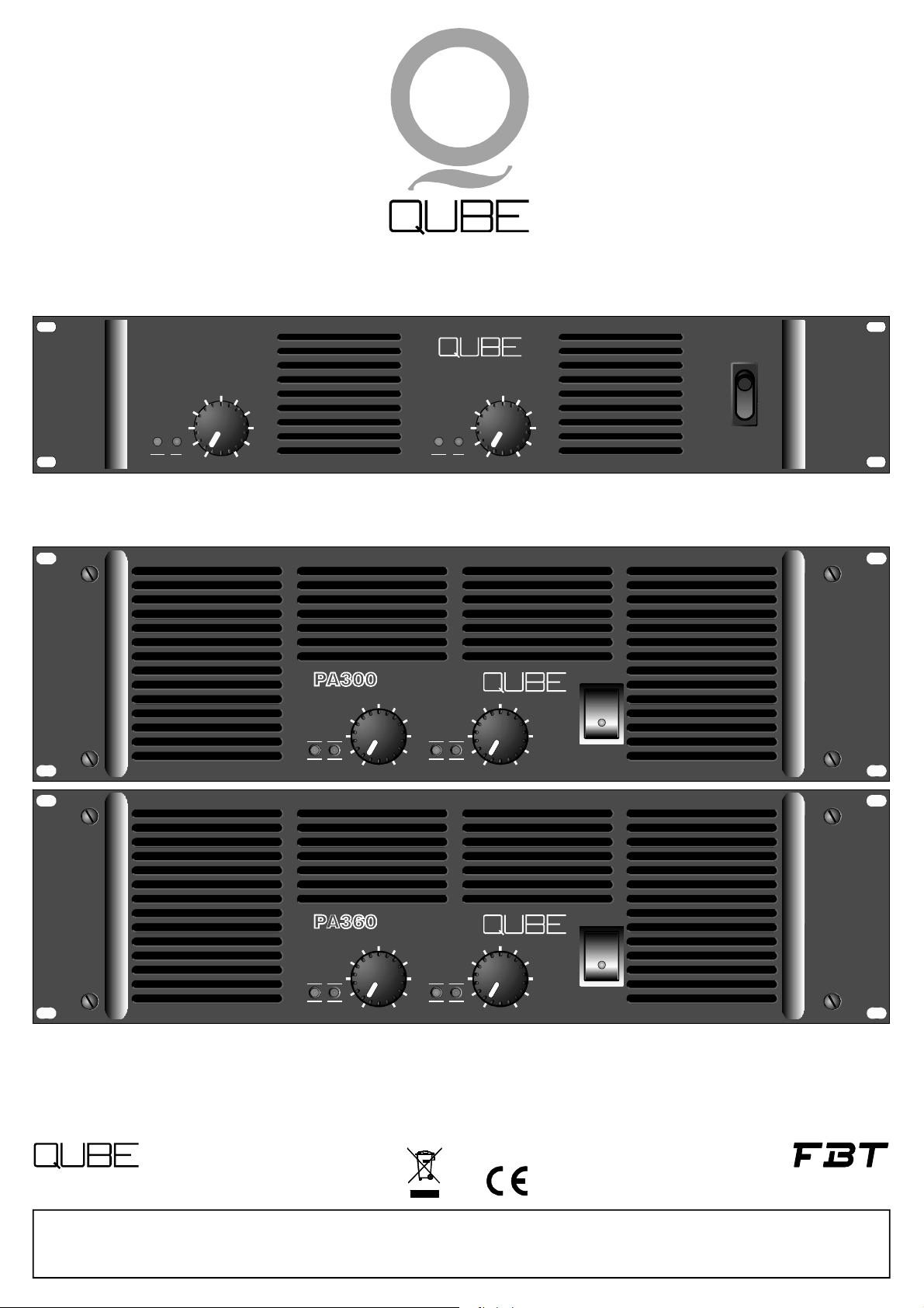
PA140
CH.2
SIG
PROT
CLIP
PWR PWRSIG SIG
G G
R R
PROT PROTCLIP CLIP
PWR
SIG
PROT
CLIP
0 100 10
CH2
100 10
POWER
POWER
Worldwidedistributor FBT
www.qubeaudio.com
FBT elettronica S.p.A. --62019RECANATI(MC)-ITALYZonaInd.leSQUARTABUE
TEL.071/750591r.a.-FAX071/7505920-P.O.BOX104-Internet:http://www.fbt.it-E-mail:info@fbt.it
POWERAMPLIFIER
CH1 CH2
PWR PWRSIG SIG
G G
R R
PROT PROTCLIP CLIP
Operatingmanual
0 100 10
POWER
FBTElettronicaS.p.A.
www.fbt.it
Page 2

CAUTIONS
RISKOFELECTRICSHOCK
DONOTOPEN
TOREDUCETHERISKOFELECTRICSHOCKDONOTREMOVE
COVER.NOUSERSERVICEABLEPARTSINSIDE
REFERSERVICINGTOQUALIFIEDSERVICEPERSONNEL
TOAVOIDELECTRICSHOCKDONOT
INSERTFINGERSOROBJECTSINTO
ANYOPENINGSINTHECABINET
TOPREVENTFIREORELECTRICSHOCKDONOTEXPOSE
THISEQUIPMENTTORAINORMOISTURE
RISKOFELECTRICSHOCK:
OPENONLYIFQUALIFIEDAS
SERVICEPERSONNEL
!
TOREITERATETHEABOVEWARNINGS:SEVICINGINSTRUCTIONS
AREFORUSEBYQUALIFIEDPERSONNELONLY.TOAVOID
ELECTRICSHOCKDONOTPERFORMANYSERVICINGOTHER
THANTHATCONTAINEDINTHEOPERATIONINSTRUCTIONS
UNLESSYOUAREQUALIFIEDTODOSO.REFERALL
SERVICINGTOQUALIFIEDPERSONNEL
INTRODUCTION
Congratulationsonyourpurchaseofadualchannelprofessionalpoweramplifiers.YourQUBE
amplifierhasbeendesignedtoprovideyearsoftrouble-free,highperformanceoperation.Wehopeyouenjoyit.
Youramplifiermayincludetheplug-inloudspeakercontrollermodulesinplaceofthestandarddualchannelinputmodule.
The“controllermodulesarededicatedcompanionstoaspecificQUBEloudspeakers.Theyprovideprotectioncircuitry,
SP”
SP
electroniccrossovercircuitryandresponseoptimizationfortheirassociatedloudspeakers.
Caution:ifyouramplifierincludesa“SP”,itisconfiguredforusewithaparticularloudspeakermodelandshouldnot
beusedwithanyothermodel.Useofthewrongloudspeakermayresultinloudspeakerdamage.
YourQUBEamplifierwascompletelytestedandinspectedbeforeleavingourfactoryandshouldhavearrivedinperfect
condition.Pleasecarefullyinspectyouramplifieranditsshippingcartonforanynoticeabledamage,andifanydamageis
found,immediatelynotufytheshippingcompany,
Onlytheconsigneemayinstituteaclaimwiththecarrierforanydamageincurredduringshipping.Besuretosavethecarton
andallpackingmaterialsforthecarrier’sinspection.
Itisalsoagoodideatosavethecartonandpackingmaterialeventhoughtheamplifierarrivedingoodcondition.Ifshipping
theamplifiershouldeverberequired,itshouldbeshippedonlyinitsoriginalfactorypacking.
Important:
YourQUBEamplifiercontainsnouser-serviceablepartsandallserviceshouldbereferredtoqualifiedservicepersonnel.We
recommendthatitbereturnedtothefactoryinitsoriginalpackingcartoniffactoryserviceisrequired.
QUBEPA140/PA300/PA360
Page 3
POWERAMPLIFIERS
ThePA140provides500Wofpowerperchannelusinga4
ohmspeakersystem(350Wperchannelwith8ohm)andis
theidealamplifierforQUBEQ112,Q115,QS112and
QS115speakers.ThePA140canalsobeconnectedtoa
controllermodule.
PA300isa1500Wperchannelpoweramplifierdesigned
forallthoseapplicationswherereliabilityandsoundquality
areextremelyimportant.Itincludesself-resetting
protectivecircuitrytopreventanydamage,withLEDs
indicatingthestatusofeachchannel.Othercharacteristics
includeagroundliftandselectorofbridgemode.PA300is
idealtobeusedcombinedwithQ115,QS115,QS118,BRH
andTRSQUBEspeakersystems.Theversatilityofthe
poweramplifierallowstheuseofcontrollermoduleto
processthesignal,optimisingtheoverallperformanceof
thespeakersandprotectingthematthesametimefrom
possibledamages.
ThePA360isa1800Wperchannelpoweramplifier
designedforallthoseapplicationswherereliabilityand
soundqualityareforprimaryimportance.Itincludesselfresettingprotectivecircuitrytosafe-guardagainstdamage,
withLEDsindicatingthestatusofeachchannel.Other
characteristicsincludeagroundliftswitchandselectorfor
simplesettingofstereobridgemode.ThePA360isidealfor
theusewithQUBEQSA210LINEARRAYspeaker,QS218
,BRKandRUT.Theversatilityofthesystemallowstheuse
ofacontrollermoduletoprocessthesignal,optimisingthe
overallperformanceofthespeakersandprotectingthemat
thesamefrompossibledamages.
ANALOGCONTROLLERS
Seepage8. Seepage8.
DIGITALCONTROLLERS
Seepage8. Seepage10.
Page 4
TECHNICALSPECIFICATIONS
Continuouspowerbothchannelsdriven
WRMS(@THD<0.05%1kHz)
ContinuouspowerBridgemode
WRMS
Impulsivepowerbothchannelsdriven
WRMS
ImpulsivepowerBridgemode
WRMS
Inputsensitivity
Inputimpedance
Slewrate
Signaltonoiseratio
Harmonicdistortion
(1kHz-4ohm)
350W@8ohm
500W@4ohm
550W@8ohm
900W@4ohm
1300W@2ohm
850W@8ohm
1200W@4ohm
1700W@2ohm
1000W@8ohm 2600W@4ohm 3400W@4ohm
470W@8ohm
700W@4ohm
600W@8ohm
1000W@4ohm
1500W@2ohm
1400W@8ohm 3000W@4ohm
900W@8ohm
1250W@4ohm
1800W@2ohm
2500W@8ohm
3600W@4ohm
1,4Veff 1,4Veff 1,4Veff
15kOhmmin. 15kOhmmin. 15kOhmmin.
>40V/s >30V/s >30V/s
107dBw/A 110dBw/A 110dBw/A
<0,015 <0,01 <0,01
IMD
TIM
Frequencyresponse
Dampingfactor
Maxoutputvoltage
Maxcurrentoutput
Powerconsumption
Powersupply
Protections
Cooling
Dimensions
Weight
Allpowermeasurementsmadeat230V
AllmeasurementsmadeusingAUDIOPRECISIONequipment
ImpulsivepowermeasuredinaccordancewithIHFmethodwith20mSburstsandREPETITIONRATE100mS
@8ohm,1kHz
(WxHxD)inch
lb.
<0,04% <0,04% <0,015%
<-80dB <-80dB <-80dB
20Hz-20kHz 20Hz-20kHz 20Hz-20kHz
>400 >400 >200
90Vp 100Vp 85Vp
25Aeff 63Aeff 84Aeff
1500VA 2800VA 3500VA
230Vac 230Vac 230Vac
DC/Thermal/SOA DC/Thermal/SOA DC/Thermal/SOA
variablespeedfan 2variablespeedfan 2variablespeedfan
19x3.5x19 19x5x19 19x5x19
40.5 66 81.5
Page 5
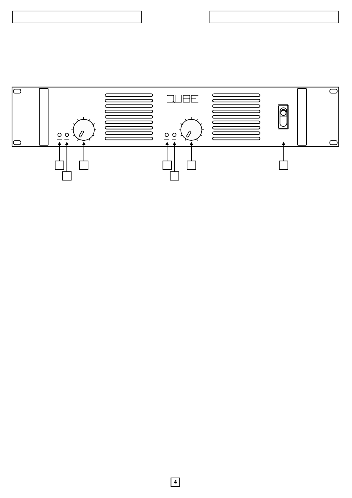
FRONTPANELFEATURES
PA140
PA140
CH.2
SIG
PROT
CLIP
1
3
2
PWR
SIG
PROT
CLIP
0 100 10
1
3
POWER
4
2
1.Channelsstatus(PROT/PWR)led
Thechannel1&2statusledglowsgreentoindicatetheamplifierisonandchannelisoperatingnormally.Itglowsredto
indicatethatoneormoreoftheamplifierchannelprotectivecircuitshasbeenactivated.Theamplifiercontainsseparateovertemperature,DConoutputandshorted-loadprotectivecircuitryforeachchannel.Wheneverafaultisdetectedtheoffending
channelistemporarily“shutdown”andthestatuslightturnedredtocallattentiontotheproblem.Thechannelwillremain“off”
untilnormaloperatingconditionsarerestored.
Note:ThestatusledisalsocontrolledbytheSP12andSP22controllersandwhenoneofthesemodulesisincluded,the
statusledwillglowredwhenoneofthesemodules’protectivecircuitshasbeenactivated.
Itisnormalforthestatusledtoglowredwhentheamplifierisfirstturnedon.Itwillthenturntoasteadygreenasasignthat
channelisonandoperatingsatisfactorily.
2.Channelssignal(SIG./CLIP)led
Thesignalledindicatesthestatusoftheamplifier’schannelsignallevel.Whenitisoff(notglowing)itshowsthat nosignalis
beingreceived.Itglowsgreentoindicateanormalsignallevelandredasanindicationthatchannelisbeingdriveninto
clipping.Occasionaloperationofthered“clip”indication(flickeringoftheredlight)isanindicationofoptimumsystem
utilization.Extendedilluminationofthered“clip”indicationisasignthesystemisbeingoverdrivenandshoudbeavoided.
3.Channeloutputattenuator
Thechanneloutputattenuatorcontrolsthegainofchannelinalloperatingmodes.Whenitisturnedfullyclockwise, the
amplifierwillhaveitsmaximumratedvoltagegainandwilldeliveritratedoutputwhendrivenbyitsratedinputsignal.Asa
generalrule,settingtheattenuatorinthefullclockwisepositionprovidesmaximumamplifierheadroom;settingthe
attenuatorsatalowerlevelmaximizesthesystemsignal/noiseratio.
Important:Whentheamplifierisbeingoperatedinthebridgeoutputmode,boththechannel1andchannel2attenuatorsmust
besetinthesamepositiontoavoidamismatchinthesignallevelbeingsenttoeachchannel.
4.Poweron/offswitch
Thisswitchisusedtoturnpowertotheamplifier“on”and“off”
Page 6

REARPANELFEATURES
5 6 7 8 9 10
PA140
OROBJECTSINTOANY
TOREDUCETHERISKOF
REMOVETHECOVER.NO
OUTPUT
CH2 CH1BRIDGE
!
CLASS2WIRING
MANUFACTUREDINEEC
CAUTIONCAUTION
FORCONTINUEDPROTECTION
AGAINSTRISKOFFIRE
REPLACEONLYWITHSAME
TYPEFUSE
WARNINGCAUTION
TOREDUCETHERISKOF
ELECTRICSHOCKDONOT
EXPOSETHISEQUIPMENT
TORAINORMOISTURE
PA140
POWERAMPLIFIER
230V
50Hz
PM22
PARALLEL
T10A
250V
STEREO
(CH1IN)
TOAVOIDELECTRICSHOCK
PIN1=GND
PIN2=
+
PIN3=
2
-
GROUNDLIFT
ON ONIN INOUT OUT OFFlink linkBRIDGE
DONOTINSERTFINGERS
OPENINGSINTHECABINET
ELECTRICSHOCKDONOT
USERSERVICEABLEPARTS
INSIDE.REFERSERVICINGTO
QUALIFIEDSERVICEPERSONNEL
2
STEREO4OHMMIN.
OUTPUTS
BRIDGEDMONO8OHMMIN.
POWERCONSUMPTION:920W
1 2 3 4
1.ACpowercord&fuse
ThefuseholderonthePA140acceptsaT10A,250V.
BeforeconnectingtheamplifierchecktheACvoltagerequirementandmakecertaintheunitisconnectedtotheproper voltage.Failureof
theunitwillresultifa120voltamplifierisconnectedtoa220Vpowerline.
2.Channel2outputconnector
4-pinNeutrikSpeakonconnectorprovidessingle-connector,quick-disconnectfacilitiesforchannel2onpins1+&1-.Pin1+isconsidered
the“hot”terminalwhilepin1-is“common”.
3.Bridgeoutputconnector
4-pinNeutrikSpeakonconnectorprovidessingle-connector,quick-disconnectfacilitiesfortheamplifier’sbridgeoutputonpins1+&1-.Both
pins1+and1-areconsidered“hot”andshouldnotbegrounded.
4.Channel1(and2)outputconnector
4-pinNeutrikSpeakonconnectorprovidessingle-connector,quick-disconnectfacilitiesforbothchannel1andchannel2outputs.The
channel1outputisonpins1+and1-andthechannel2outputonpins2+and2-.Pins1+and2+areconsidered“hot”whilepins1-and2-are
“common”.
Standardinputmodule
5.Stereo-Parallel-Bridgeoutputmodeselector
Theoutputmodeselectorallowstheamplifiertobeoperatedin3differentoutputmodes.
stereo
Inthemodethetwochannelsoperateindependently,justastheydoinastereoamplifier:signalsfedintothetwoamplifierinputsare
amplifiedseparatelyanddeliveredinphasetooutputs1and2.Theoutputlevelsarecontrolledseparatelybythefrontpanelmounted
attenuators.
parallel
Inthemodeinput2isdisabledandthetwoamplifierchannelsoperateinparallelfromasingleinputsignalfedintothechannel1
input.Thiseliminatestheneedtoinstallajumpercabletooperatetheamplifierchannelsinparallel.Theoutputsareseparateandinphase
andbothinputattenuatorsareactivetopermitdifferentlevelsettingsforeachchannel.
bridge
Inthemodeasinglesignalisfedintothechannel1inputwhichdrivesbothoutputchannelsintandem.Theoutputisdeliveredtothe
bridgeoutputconnector.Thismodeallowsthetwoamplifieroutputstobestrappedtogether(”bridged”)toproduceasingleoutputwith
doublethepowercapabilitesofasinglechannel.Input2isdisabled.Bothinputattenuatorsareactiveandmustbesettothesamelevel.
Notethatinbridgemodebothsidesoftheoutputshouldbeconsideredhotandshouldnotbegrounded.
6.Channel2audioinputconnector
Female3-pinXLRtypeinputconnectorforchannel2.Theinputiselectronicallybalanced.Werecommendtheuseofpin2as“hot”andpin3
as“neutral”.Pin1ischassisground.Whentheamplifierisconnectedtoabalancedsourcetheshieldmayeitherbeliftedorconnectedatthe
sourceend.Thechoiceshouldbemadeonthebasisofminimumhum.
Withanunbalancedsourceconnectthesignaltopin2andsourcegroundtopin3;connectingthesignaltopin3isnotrecommendedasthis
willcausea180phaseinversionattheamplifieroutputs.
areusedforanunbalancedinput.
7.Channel2“loopingoutput”connector
Male3-pinXLRtype“loopingoutput”connectorforchannel2usedto“loopthrough”toadditionalamplifiers.
8.Channel1“loopingoutput”connector
Male3-pinXLRtype“loopingoutput”connectorforchannel1usedto“loopthrough”toadditionalamplifiers.
9.Channel1audioinputconnector
Female3-pinXLRtypeinputconnectorforchannel1.Referto“6”abovefordetails.
10.Groundliftswitch
TheGroundLiftswitchisusedtoseparatethesignalgroundcircuitfromtheamplifiergroundcircuitandthus,eliminatehuminducedby
groundloops.
Intheleft“ON”positionthesignalgroundiselectricallydisconnectedfromtheamplifiergroundcircuit(thechassis).
Inthecenter“OFF”positiontheinputsignalgroundiselectricallyconnectedtotheamplifiergroundcircuit(thechassis).
Intheright“ON”positionanACconnectionisprovidedbetweenthesignalgroundandtheamplifiergroundcircuit(thechassis).
Note:improperoperationresultswhenonlypin2oronlypin3andpin1(ground)
Page 7

FRONTPANELFEATURES PA300/PA360
PA300
CH2
PWR PWRSIG SIG
G G
R R
PROT PROTCLIP CLIP
100 10
POWER
1
3
1
2
PA360
POWERAMPLIFIER
CH1 CH2
PWR PWRSIG SIG
G G
R R
PROT PROTCLIP CLIP
1
3
1
2
3
4
2
0 100 10
3
POWER
4
2
1.Channelsstatus(PROT/PWR)led
Thechannel1&2statusledglowsgreentoindicatetheamplifierisonandchannelisoperatingnormally.Itglowsredto
indicatethatoneormoreoftheamplifierchannelprotectivecircuitshasbeenactivated.Theamplifiercontainsseparateovertemperature,DConoutputandshorted-loadprotectivecircuitryforeachchannel.Wheneverafaultisdetectedtheoffending
channelistemporarily“shutdown”andthestatuslightturnedredtocallattentiontotheproblem.Thechannelwillremain“off”
untilnormaloperatingconditionsarerestored.
Note:ThestatusledisalsocontrolledbytheSP12andSP22controllersandwhenoneofthesemodulesisincluded,the
statusledwillglowredwhenoneofthesemodules’protectivecircuitshasbeenactivated.
Itisnormalforthestatusledtoglowredwhentheamplifierisfirstturnedon.Itwillthenturntoasteadygreenasasignthat
channelisonandoperatingsatisfactorily.
2.Channelssignal(SIG./CLIP)led
Thesignalledindicatesthestatusoftheamplifier’schannelsignallevel.Whenitisoff(notglowing)itshowsthat nosignalis
beingreceived.Itglowsgreentoindicateanormalsignallevelandredasanindicationthatchannelisbeingdriveninto
clipping.Occasionaloperationofthered“clip”indication(flickeringoftheredlight)isanindicationofoptimumsystem
utilization.Extendedilluminationofthered“clip”indicationisasignthesystemisbeingoverdrivenandshoudbeavoided.
3.Channeloutputattenuator
Thechanneloutputattenuatorcontrolsthegainofchannelinalloperatingmodes.Whenitisturnedfullyclockwise, the
amplifierwillhaveitsmaximumratedvoltagegainandwilldeliveritratedoutputwhendrivenbyitsratedinputsignal.Asa
generalrule,settingtheattenuatorinthefullclockwisepositionprovidesmaximumamplifierheadroom;settingthe
attenuatorsatalowerlevelmaximizesthesystemsignal/noiseratio.
Important:Whentheamplifierisbeingoperatedinthebridgeoutputmode,boththechannel1andchannel2attenuatorsmust
besetinthesamepositiontoavoidamismatchinthesignallevelbeingsenttoeachchannel.
4.Poweron/offswitch
Thisswitchisusedtoturnpowertotheamplifier“on”and“off”
Page 8

REARPANELFEATURES PA300/PA360
5 6 7 8 9
PM22
PARALLEL
STEREO
(CH1IN)
2
WARNING:
TOAVOIDELECTRICSHOCK,
TOREDUCETHERISKOF
DONOTINSERTFINGERSOR
ELECTRICSHOCKDONOT
OBJECTSINTOANYOPENINGS
EXPOSETHISEQUIPMENT
TORAINORMOISTURE
AVIS
RISQUEDECHOCELECTRIQUE
NEPASOUVRIR
POWERCONSUMPTION:2700VA
PA300
CODE16963
CAUTION:
INTHECABINET
TOREDUCETHERISKOFELECTRIC
SHOCK,DONOTREMOVETHECOVER.
NOUSERSERVICEABLEPARTSINSIDE.
REFERSERVICINGTOQUALIFIED
SERVICEPERSONNEL.
CAUTION
RISKOFELECTRICSHOCK
DONOTOPEN
10
PIN1=GND
PIN2=
+
PIN3=
-
GROUNDLIFT
ON ONIN INOUT OUT OFFlink linkBRIDGE
OUTPUT
CAUTION:
CH2
CLASS2WIRING
!
CH2OUT BRIDGEOUT CH1OUT
STEREO2OHMMIN./BRIDGEDMONO4OHMMIN.
CH1BRIDGE
PA300
POWERAMPLIFIER
LINEPROTECT
230V50Hz
MADEINITALY
12 3 4
1.Lineprotect(circuitbreaker)
Circuitbreakerandassociated“lineprotect”switchprovideoverallprotection;mustbemanuallyreset.
2.Channel2outputconnector
4-pinNeutrikSpeakonconnectorprovidessingle-connector,quick-disconnectfacilitiesforchannel2onpins1+&1-.Pin1+isconsidered
the“hot”terminalwhilepin1-is“common”.
3.Bridgeoutputconnector
4-pinNeutrikSpeakonconnectorprovidessingle-connector,quick-disconnectfacilitiesfortheamplifier’sbridgeoutputonpins1+&1-.Both
pins1+and1-areconsidered“hot”andshouldnotbegrounded.
4.Channel1(and2)outputconnector
4-pinNeutrikSpeakonconnectorprovidessingle-connector,quick-disconnectfacilitiesforbothchannel1andchannel2outputs.The
channel1outputisonpins1+and1-andthechannel2outputonpins2+and2-.Pins1+and2+areconsidered“hot”whilepins1-and2-are
“common”.
5.Stereo-Parallel-Bridgeoutputmodeselector
Theoutputmodeselectorallowstheamplifiertobeoperatedin3differentoutputmodes.
stereo
Inthemodethetwochannelsoperateindependently,justastheydoinastereoamplifier:signalsfedintothetwoamplifierinputsare
amplifiedseparatelyanddeliveredinphasetooutputs1and2.Theoutputlevelsarecontrolledseparatelybythefrontpanelmounted
attenuators.
parallel
Inthemodeinput2isdisabledandthetwoamplifierchannelsoperateinparallelfromasingleinputsignalfedintothechannel1
input.Thiseliminatestheneedtoinstallajumpercabletooperatetheamplifierchannelsinparallel.Theoutputsareseparateandinphase
andbothinputattenuatorsareactivetopermitdifferentlevelsettingsforeachchannel.
bridge
Inthemodeasinglesignalisfedintothechannel1inputwhichdrivesbothoutputchannelsintandem.Theoutputisdeliveredtothe
bridgeoutputconnector.Thismodeallowsthetwoamplifieroutputstobestrappedtogether(”bridged”)toproduceasingleoutputwith
doublethepowercapabilitesofasinglechannel.Input2isdisabled.Bothinputattenuatorsareactiveandmustbesettothesamelevel.
Notethatinbridgemodebothsidesoftheoutputshouldbeconsideredhotandshouldnotbegrounded.
6.Channel2audioinputconnector
Female3-pinXLRtypeinputconnectorforchannel2.Theinputiselectronicallybalanced.Werecommendtheuseofpin2as“hot”andpin3
as“neutral”.Pin1ischassisground.Whentheamplifierisconnectedtoabalancedsourcetheshieldmayeitherbeliftedorconnectedatthe
sourceend.Thechoiceshouldbemadeonthebasisofminimumhum.
Withanunbalancedsourceconnectthesignaltopin2andsourcegroundtopin3;connectingthesignaltopin3isnotrecommendedasthis
willcausea180phaseinversionattheamplifieroutputs.
Note:improperoperationresultswhenonlypin2oronlypin3andpin1(ground)
areusedforanunbalancedinput.
7.Channel2“loopingoutput”connector
Male3-pinXLRtype“loopingoutput”connectorforchannel2usedto“loopthrough”toadditionalamplifiers.
8.Channel1“loopingoutput”connector
Male3-pinXLRtype“loopingoutput”connectorforchannel1usedto“loopthrough”toadditionalamplifiers.
9.Channel1audioinputconnector
Female3-pinXLRtypeinputconnectorforchannel1.Referto“6”abovefordetails.
10.Groundliftswitch
TheGroundLiftswitchisusedtoseparatethesignalgroundcircuitfromtheamplifiergroundcircuitandthus,eliminatehuminducedby
groundloops.
Intheleft“ON”positionthesignalgroundiselectricallydisconnectedfromtheamplifiergroundcircuit(thechassis).
Inthecenter“OFF”positiontheinputsignalgroundiselectricallyconnectedtotheamplifiergroundcircuit(thechassis).
Intheright“ON”positionanACconnectionisprovidedbetweenthesignalgroundandtheamplifiergroundcircuit(thechassis).
Page 9

ANALOGCONTROLLERS SP12BRK/SP12RUT
1 = GND
PIN 2 = +
PIN 3 =
-
BRK
LOOPINGOUTHFOUT INPUT LOOPINGOUT LFOUT
TheSP12BRKmonocontrollerhasbeendesignedtooptimise
theoverallperformanceofQUBEBRKspeakers.Themodule
slotsintothebackofPA300andPA360amplifiers.TheSP12
BRKprovidesthesystemwithanequalisationstagethatimproves
speakerfrequencyresponseand,thankstoacombinationof
protectionsystems,preventsdamagetotheconeswhendrivenat
maximumpower.
PIN 1 = GND
PIN 2 = +
PIN 3 =
-
SP12
RUT
INPUT LOOPINGOUTLOOPINGOUT SUBOUTSUBOUT
GNDLIFT
TheSP12RUTcontrollerincorporateahighpasscrossoverfilter
pilotingthefull-rangesectionofthesystemaswellasprotection
circuitsdesignedtopreventdamagetotheconeswhendrivenat
maximumpower.
DIGITALCONTROLLERS SP22D/SP22Ds
STEREO
PARALL.
BRIDGE
2 3 4 234
QS112
QS112 CH1+CH2
QS115
QS115 CH1+CH2
METERSDELAYPRESET
QS118
QS118 CH1+CH2
QS218
QS218 CH1+CH2
SP22-Ds
BRIDGE
PARALLEL
PIN1=GND
PIN 2 = +
PIN 3 =
1 2 3 4ON1 2 3 4 5 6 7 8
IN LINK INLINK
-
CH2 CH1
GND
LIFT MODE
PHASE
SPKR
SEL.
.125
ON
.25
.51248
16
1 12 23 4 5 6
BIAMPMODE:
OUTCH1LOW
OUTCH2HIGH
STEREO
PARALL.
BRIDGE
BIAMP
PIN1=GND
PIN 2 = +
PIN 3 =
SP22
isa2-in/2-outdigitalsignalprocessor(DSP)designedtooptimisetheperformanceofallloudspeakersintheQUBErange.
SP22
ModelareeasilyinstalledintherearpanelofaQUBEamplifier,oritcanberack-mountedwhenusingotherpoweramplifiers(inthis
casetheadapterisusedtoinstalltwoSP22modules).
Modelisdesignedforusewith2-wayfull-rangespeakers(Q106,Q208,Q110,Q112,Q115,QM115);modelisdesignedfor
HCR12/22
SP22DSP22Ds
IN
-
CH2 CH1
LINK
GND
LIFT MODE
2 3 4 2 3 4
Q106
Q106+QS112
Q110
Q112
METERSDELAYPRESET
SPKR
SEL.
1 2 3 4 5 6 7 8
ON
.25
.125
.51248
1 2 3 4
ON
SUB
Q115
QM115
QM115STAGE
Q208
16
SP22-D
LINK
usewithsubwoofers(QS112,QS115,QS118,QS218).
Themaincharacteristicsareasfollows:
°Frequencyrangeequalisationtooptimisefrequencyresponseandpowerresponse.
°Highprecisioncontrolofpowerdeliveredtoloudspeakersbymeansofanamplifieroutputsensingfunction.
°Wooferexcursioncontrol
°Highpassfilter
°Fastrolloffcrossovers(steepslope)
°Delaysonbothchannelstocompensateforverticalmisalignment
°Generaldelayonbothchannelsfrom0.25mto64m.
°4configurationmodes:stereo/biamp/bridge/parallel
°2XLRinputs
°2parallelXLRoutputs
°8dipswitchestochangethedelayonbothchannels
°4-positionselectorfor4configurationmodes:stereo/biamp/bridge/parallel
°1dipswitch(1)forSUB/PHASEselection: SUBmodeactivatesthehighpassfilterwhenSP22isutilisedtocontrolasatellite;forthe
modelSP22DsPHASEmodeinvertsthephase(180deg.rotation)onthesubwoofer
°3dipswitches(2/3/4)toselectcabinetmodel(8models)
BIAMP
BRIDGE
PARALLEL
IN
Page 10

DIGITALCONTROLLERS SP22D/SP22Ds
TheprocessorisequippedwithtwoXLRbalancedsignalinputsdesignated;theseinputscorrespondtotwooutputsin
Ch1andCh2(1)“link”XLR(2)
paralleltotheinputs.
GND/LIFT(3)
MODE(4)
:switchtoisolatethechassisgroundandthesignalgroundtoavoidgroundloops,whichcancausehumproblems.
:selectortochoosetheprocessoroperatingmode.
Stereo:channelsCh1andCh2arecompletelyindependent.
Parallel:inthismodetheprocessoracceptsonlyaninputonCh1,whichdrivesboththeoutputs.
Bridge:inputonlyonCh1with180degreephasedifferenceontheoutputs;connectthespeakertotheamplifierbridgeoutput.
Biamp(onlySP22D):inputonlyonCh1;connectamplifieroutputCh1tothewoofer(LF)andoutputCh2tothetweeter(HF).Inthismodethespeaker
crossoversettoBI-AMPmode.
mustbe
OnQUBEamplifierstheoutputofbothchannelscanbeconnectedbymeansofa4-corecabledirectlyfromtheCH1Speakon,whichcarriesLFon1+/1-and
HFon2+/2-.
PRESET(5)
:thefirstofthese4dipswitchesprovidesdifferentfunctionsforthetwoprocessors;ontheSP22DunitthisdipswitchisdesignatedSUBandwhen
settothedownposition(ON)itactivatesaHI-PASSfilteratapproximately100Hz-24dB/octonbothchannels.Tobeusedwhenthesystemisequippedwitha
subwooferwithrelativeSP22Dsprocessor.WhensettoOFFthesystemoperatesinfull-rangemodewithexclusivelyasubsonicfilter.
OntheSP22DsthefirstdipswitchisdesignatedPHASEandwhensettothedownposition(ON)bothoutputsfeatureaphasedifferenceof180degreeswith
respecttotheinput.
ThismaybeusefultooffsetpossiblephaseinversionsonthecablesortomaximisetheacousticefficiencyofSUB+SAT inthecrossoverzone.
Theotherthreedipswitches(sharedbybothprocessors)designatedSPKRSELECTORservetoselectthemodelofspeakerutilised.
SelectionofthespeakermodelisimportantbecausetheprocessorparametersarecalibratedinrelationtoeachQUBEspeakersystemmodel.
N.B.theuseofaspeakerotherthantheonesetontheSP22Dprocessormaycauseirreversibledamagetothespeakerandsignificantworsening
ofsoundreproductionperformance.
Figures1and2showalistofthespeakersutilisablewitheachprocessor.
METERSDELAY(6):theeightdipswitchescontroladigitaldelaylineonbothchannels;thismeansthatitispossibletocompensatefor misalignmentof
subwoofersandsatellitesontheverticalplaneorcreatedistributedlinesofspeakerswhosesoundreachesthelisteningpointatthesametime,thereby
avoidingundesirableechoes.
Thedelaytimeisdefinedinmetresfrom0.125to31.875in12.5cmsteps.
E.g.:toseta18.625mdelaysetthefollowingdipswitchestothedownposition:no.1(16m),no.4(2m),no.6(0.5m)and no.8(0.125m),foratotalof
16+2+0.5+0.125=18.625m.
WARNING:
Theprocessoraffectsthesignalup-linefromthevolumecontrol,soreducingtheamplifiervolumeexcessivelyleadstotheriskofoverloadingtheSP22D
inputbeforebringingtheamplifieruptofullpower.
Itisadvisabletoworkwithamplifiervolumefrombetweenhalftofullpower.
BeforeadjustingtheMODEandSPKRSELECTORcontrolshighintensitysignalsmaybeproducedwhilenewdataare
alwaysswitchofftheamplifier:
beingdownloadedtothememory,withtheconsequentriskofdamagingthespeakers.
2 3 4
Q106
Q106+QS112
Q110
Q112
Q115
QM115
QM115STAGE
Q208
2 3 4
QS112
QS112 CH1+CH2
PassivespeakerQ106
Passivesystemcomposedof2xQ106unitscombinedwithaQS112subwoofer.Theamplifieris
connectedtospeakerQS112,whiletheQ106unitsareconnectedtotheoutputsofunitQS112.
ThisconfigurationdoesnotworkinBIAMPmode.
PassivespeakerQ110
PassivespeakerQ112
PassivespeakerQ115
PassivespeakerQM115AutilisedastheMainPA(nottobeusedasStagemonitor)
PassivespeakerQM115utilisedasastagemonitorplacedonthefloororonthestage
PassivespeakerQ208
PassivesubwooferQS112;disablethepassiveCX-OVERbymeansoftheswitchontheloudspeaker
Thetwoinputsaresummedtogether.Thisfacilityisextremelyusefulwhenconfiguringsystemswith2
satellitesandasinglesubwoofer.Thisconfiguration doesnotworkinSTEREOmode.
INPUTS:
#2xXLRelectronicallybalanced
#Impedance:>10kOhm
OUTPUTS:
#2xXLR(link)
PERFORMANCE:
#Dynamicrange:>110dB20Hz-20kHzlin
#Distortion:<0,02%@1kHz/+18dBm
#Max.delay:31,875mt.
#Min.stepdelay:0,125mt.
#Maxinputlevel:12,5Vrms
#Maxoutputlevel:2,8Vrms
QS115
QS115 CH1+CH2
QS118
QS118 CH1+CH2
QS218
QS218 CH1+CH2
PassivesubwooferQS115
Thetwoinputsaresummedtogether.Thisfacilityisextremelyusefulwhenconfiguringsystemswith2
satellitesandasinglesubwoofer.Thisconfiguration doesnotworkinSTEREOmode.
PassivesubwooferQS118
Thetwoinputsaresummedtogether.Thisfacilityisextremelyusefulwhenconfiguringsystemswith2
satellitesandasinglesubwoofer.Thisconfiguration doesnotworkinSTEREOmode.
PassivesubwooferQS218
Thetwoinputsaresummedtogether.Thisfacilityisextremelyusefulwhenconfiguringsystemswith2
satellitesandasinglesubwoofer.Thisconfiguration doesnotworkinSTEREOmode.
EQ.&FILTERS:
#8fullparametricequalizer
#24dB/oct.HPfilter
#24dB/oct.LPfilter
#Dynamicbassequalization
ADDITIONALFEATURES:
#Truepowerlimiterwith2channel
sensinginputs
#Noisegate
Page 11

DIGITALCONTROLLERS HCR12-22
hostingcontrollerrack
ProcessorsSP22DandSP22Dscannotfunctionindependently:theymustalwaysbeinstalledinahost-unitcomposedof QUBEPA140,
PA300,PA360poweramplifiers.
UsingunitHCR12-22asthehostmakesitpossibletouseamplifiersofdifferentmanufacturerstodriveQUBEseriesloudspeakers
CH1 CH2
CH1 CH2PRT PRT
AMP1 AMP2
UNBAL. UNBAL.
CH2OUT CH1OUT
PIN1=GND
PIN 2= +
PIN 3=
-
IN LINK INLINK
CH2 CH1
CH2 CH1
LINK LINK
BIAMPMODE:
OUTCH1LOW
OUTCH2HIGH
STEREO
PARALL.
BRIDGE
BIAMP
GND
LIFT MODE
SENSING SENSING
2 3 4 2 3 4
Q106
Q106+QS112
Q110
Q112
1 2 3 4ON1 2 3 4 5 6 7 8
SPKR
SUB
SEL.
METERSDELAYPRESET
ON
.25.5124816
.125
Q115
QM115
QM115STAGE1
QM115STAGE2
BIAMP
BRIDGE
PARALLEL
AMP
2
1
50Hz
PIN1=GND
PIN2 =+
IN LINK INLINK
PIN3 =
-
CH1OUT
GND
CH2 CH1
LIFT MODE
CH2 CH1
LINK LINK
2 3 4 2 3 4
QS112CH1+CH2
STEREO
PARALL.
QS115CH1+CH2
BRIDGE
1 2 3 4ON1 2 3 4 5 6 7 8
SPKR
PHASE
SEL.
SENSING SENSING
QS112
QS118
QS118CH1+CH2
QS115
QS218
QS218CH1+CH2
METERSDELAYPRESET
ON
.25.5124816
.125
BRIDGE
PARALLEL
HCR12-22isa2-rackunitsystemdesignedtoaccommodateandpowertwoSP22DorSP22Dsprocessors,equippedwithallthe
necessaryconnectorsforcorrectinterfacingofprocessorsandamplifiers.
TherearpaneloftheHCR12-22processorisequippedwith12connectors(6foramplifier“1”and6foramplifier“2”);2XLR-Msockets
(CH1/CH2)carrytheoutputsfortheunbalancedandprocessedsignaloutputs,tobeconnectedtotheamplifierinputs.
2“Sensing”Speakonstowhichtheamplifierpoweroutputsaretobeconnected;2"Link"Speakonsforconnectionoftheloudspeakers.
TheSpeakonsuseexclusivelythe1+/1-terminals.CAUTION:donotinvertCH1andCH2inthesignalpathfrominputtooutput(see
exampleinfig.3).
SincetheXLRsignaloutputsareunbalanced,theconnectionsbetweentheoutputsandthepowerstageinputsmustbeasshortaspossible
toavoidhumproblems.
TheuseofHCR12-22isnotrecommendedwithamplifiersofhigherpowerthan1200W/8ohm,2000W/4ohm,2500W/2ohmperchannel.
435mm
Page 12

AMPLIFIERSETUPANDOPERATION
Amplifiersetupandoperation
Mounting
Theamplifiersaredesignedtobemountedinstandard19”racks.Theyhave4frontpanelmountingscrews.Becauseoftheir
depthandweightitisimperativethattheamplifierbesupportedattherearinanyportableapplication.
Cooling
Bothamplifiersarefancooledanditisimportantthatanamplesupplyofairisprovidedatthefrontoftheamplifierandafreeair
exhaustspaceisprovidedattherearoftheamplifier.Theinternalfanprovidesadequatecoolingwhentherackhasan open
backandthefrontisnotobstructed.Closedbackracksmayneedtobepressurizedandprovidedwithanexhaustfanto
ensureadequateairmovement.
Multipleamplifiersmaybestackeddirectlyontopofeachother.Theirisnoneedtoseparatethemwithablank(spacer)panel.
Keepinmindthatalmostallamplifiersradiatea50/60Hzmagnetichumfieldfromtheirpowertransformers.Itisprudentto
provideatleastonerack-spacebetweenanysignalprocessingequipmentandthenearestamplifiertoreducethepossibility
ofinducedhum.
Wiresize
Thesizeofthespeakerwiringneededdependsonthelenghtofthecable.Wegenerallyrecommendtheuseof12AWGfor
cablesupto30meters(approximately100feet)inlenght. Thefollowingtableshowsthesignallossin30metersofcable
drivinga4ohmload:
WireGauge(AWG)1012141618
SignalLoss(dB).44.691.071.652.49
Usinghigherwattageamplifiersthanactuallyneededisacceptablewhencontrollermodulesareusedasthecontrollerwill
keeppeakpowerlevelswithintheacceptablelimitsfortheassociatedloudspeaker(s).
Verificationofproperoperation
Beforeapplyingpowertothesystem,traceandverifyallconnections.
Caution:operatingthesystematfulllevelcandamageyourhearing.Wearearprotectorsanddonotpositionyourselfinfront
oftheloudspeakers.
MakecertainalltheModeselectorswitchesaresetinthedesiredmodeandthatoutputsareproperlyconnected.
Loudspeakerdamagemayoccurif,forexample,theSuboutputsareconnectedtothehighfrequencydriversandnottothe
Subs!
Setthepoweramplifiergaincontrolstotheirminimumposition.
Turnonthepoweramplifiersandslowlyturntheamplifierlevelcontrolstotheirmaximumpositiononeatatime.Whileyouare
doingthis,verifythatastheamplifiergainisincreasedtheappropriateresponseisobtained(i.e.thesubchannelisconnected
tothesubwoofers).Moderatelevelaudioshouldbeheardfromtheloudspeakers.
GraduallyincreasethesignallevelwhileobservingthesignalLED’s.Asthelevelincreasestheyshouldbegintoflickerred.As
thelevelcontinuestoincreasetheywillbeonforlongerperiodsoftime.
protectionLED’sareilluminatedcontinuously.
Donotoperatethesystematalevelwherethe
Ifasyouareincreasingthelevel,youhearasuddenlossofonechannelandseeilluminationofaredStatusLED,this
indicatesoneoftheamplifiersprotectivecircuitshasbeenactivated.Turntheamplifieroff,reducethegainandthenturnthe
amplifieronagain.
Page 13

WIRINGDIAGRAM
Ch2input
Ch1input
PM22
STEREO
PARALLEL
(CH1IN)
2
WARNING:
TOAVOIDELECTRICSHOCK,
TOREDUCETHERISKOF
DONOTINSERTFINGERSOR
ELECTRICSHOCKDONOT
OBJECTSINTOANYOPENINGS
EXPOSETHISEQUIPMENT
TORAINORMOISTURE
AVIS
RISQUEDECHOCELECTRIQUE
NEPASOUVRIR
POWERCONSUMPTION:2700VA
PA300
CODE16963
CAUTION:
INTHECABINET
CAUTION:
TOREDUCETHERISKOFELECTRIC
SHOCK,DONOTREMOVETHECOVER.
NOUSERSERVICEABLEPARTSINSIDE.
REFERSERVICINGTOQUALIFIED
SERVICEPERSONNEL.
CAUTION
RISKOFELECTRICSHOCK
DONOTOPEN
!
CH2OUT BRIDGEOUT CH1OUT
STEREO2OHMMIN./BRIDGEDMONO4OHMMIN.
PIN1=GND
PIN2=
+
PIN3=
-
GROUNDLIFT
ON ONIN INOUT OUT OFFlink linkBRIDGE
CH2
OUTPUT
CLASS2WIRING
Loopinginputstoadditionalpoweramplifiers
ifadditionalpoweramplifiersareneeded.
CH1BRIDGE
PA300
POWERAMPLIFIER
LINEPROTECT
230V50Hz
MADEINITALY
Channel1
Channel2
Channel1and2outputs
toloudspeakers
BRIDGEOPERATION
Input
PM22
STEREO
PARALLEL
(CH1IN)
WARNING:
TOAVOIDELECTRICSHOCK,
TOREDUCETHERISKOF
DONOTINSERTFINGERSOR
ELECTRICSHOCKDONOT
OBJECTSINTOANYOPENINGS
EXPOSETHISEQUIPMENT
TORAINORMOISTURE
AVIS
RISQUEDECHOCELECTRIQUE
NEPASOUVRIR
POWERCONSUMPTION:2700VA
CODE16963 PA300
CAUTION:
INTHECABINET
12
CAUTION:
TOREDUCETHERISKOFELECTRIC
SHOCK,DONOTREMOVETHECOVER.
NOUSERSERVICEABLEPARTSINSIDE.
REFERSERVICINGTOQUALIFIED
SERVICEPERSONNEL.
CAUTION
RISKOFELECTRICSHOCK
!
DONOTOPEN
CH2OUT BRIDGEOUT CH1OUT
STEREO2OHMMIN./BRIDGEDMONO4OHMMIN.
PIN1=GND
PIN2=
+
PIN3=
-
GROUNDLIFT
ON ONIN INOUT OUT OFFlink linkBRIDGE
CH2
OUTPUT
CLASS2WIRING
Loopinginputtoadditionalpoweramplifiers
ifadditionalpoweramplifiersareneeded.
CH1BRIDGE
PA300
POWERAMPLIFIER
LINEPROTECT
230V50Hz
MADEINITALY
Bridgedoutput
Bridgedoutputtoloudspeakers
Page 14

CONNECTIONEXAMPLES
PA140
PA140
SIG
PROT
CLIP
PIN1=GND
PIN2= +
PIN3 =
-
IN LINK INLINK
CH2 CH1
BIAMPMODE:
OUTCH1LOW
OUTCH2HIGH
STEREO
PARALL.
BRIDGE
BIAMP
GND
LIFT MODE
SP22D
CH.2
PWR
SIG
PROT
CLIP
23 4234
Q106
Q106+QS112
Q110
Q112
12 3 4ON12 3 45 67 8
SPKR
SUB
SEL.
.25.5124816
POWER
BIAMP
Q115
QM115
QM115STAGE
Q208
BRIDGE
PARALLEL
0 100 10
METERSDELAYPRESET
ON
.125
ININ
SP22D
2 3 4 234
Q106
Q106+QS112
Q110
Q112
PRESET
1 2 3 4
ON
SUB
METERSDELAY
SPKR
SEL.
.125
1 2 3 4 5 6 7 8
ON
.25.5124816
Q115
QM115
QM115STAGE
Q208
Q110
QS115
4OHM
PA300(1canale/)1channel
PA140
POWERAMPLIFIER
CH.1
SIG
PROT
CLIP
PIN1=GND
PIN2 = +
PIN3=
-
IN LINK INLINKCH2 CH1
CH.2
PWR
SIG
PROT
CLIP
0 100 10
SP22Ds
23 4 2 34
QS112
QS112CH1+CH2
STEREO
QS115
PARALL.
QS115CH1+CH2
BRIDGE
METERSDELAYPRESET
12 3 4ON1 23 45 6 78
ON
GND
SPKR
LIFT MODE
.125
PHASE
SEL.
.25.5124816
POWERPWR
QS118
QS118CH1+CH2
QS218
QS218CH1+CH2
BRIDGE
PARALLEL
Q110
SP22Ds
2 3 4 2 3 4
QS112
QS112 CH1+CH2
QS115
QS115 CH1+CH2
METERSDELAYPRESET
1 2 3 4ON1 2 3 4 5 6 7 8
PHASE
SPKR
SEL.
.125
ON
.25
.51248
QS118
QS118 CH1+CH2
QS218
QS218 CH1+CH2
16
Q106
QS112
PA140
PA140
POWERAMPLIFIER
CH.1
PWR
SIG
PROT
CLIP
BIAMPMODE:
OUTCH1LOW
OUTCH2HIGH
STEREO
PARALL.
BRIDGE
PIN1=GND
PIN2 = +
PIN3=
-
BIAMP
GND
MODE
LINK
LIFT
CH2 CH1
SP22D
CH.2
PWR
SIG
PROT
CLIP
0 100 10
23 4 23 4
Q106
Q106+QS112
Q110
Q112
12 3 4ON1 23 45 6 78
SPKR
SUB
SEL.IN
.125
HPFILTEREDOUTHPFILTEREDOUT
ININ
Q106
SP22D
2 3 4 2 3 4
1 2 3 4
ON
SUB
Q106
Q106+QS112
Q110
Q112
SPKR
SEL.
METERSDELAYPRESET
1 2 3 4 5 6 7 8
ON
.25.5124816
.125
POWER
BIAMP
Q115
QM115
QM115STAGE
Q208
METERSDELAYPRESET
ON
.25.5124816
BRIDGE
PARALLEL
LINK
IN
Q115
QM115
QM115STAGE
Q208
Page 15

STEREO
PARALLEL ON ONIN INOUT OUT OFFlink linkBRIDGE
12
PIN1=GND
PIN2=
+
PIN3=
-
12
GROUNDLIFT
(CH1IN)
OUTPUT
CH2
CLASS2WIRING
CH1BRIDGE
PA300
POWERAMPLIFIER
LINEPROTECT
230V50Hz
MADEINITALY
WARNING:
TOREDUCETHERISKOF
ELECTRICSHOCKDONOT
EXPOSETHISEQUIPMENT
TORAINORMOISTURE
AVIS
RISQUEDECHOCELECTRIQUE
NEPASOUVRIR
POWERCONSUMPTION:2700VA
CODE16963 PA300
CAUTION:
TOAVOIDELECTRICSHOCK,
DONOTINSERTFINGERSOR
OBJECTSINTOANYOPENINGS
INTHECABINET
CAUTION:
TOREDUCETHERISKOFELECTRIC
SHOCK,DONOTREMOVETHECOVER.
NOUSERSERVICEABLEPARTSINSIDE.
REFERSERVICINGTOQUALIFIED
SERVICEPERSONNEL.
CAUTION
RISKOFELECTRICSHOCK
!
DONOTOPEN
CH2OUT BRIDGEOUT CH1OUT
STEREO2OHMMIN.BRIDGEDMONO4OHMMIN.
PA360
CONNECTIONEXAMPLES
2
PARALLEL
BRIDGE
CAUTION:
WARNING:
TOAVOIDELECTRICSHOCK,
TOREDUCETHERISKOF
DONOTINSERTFINGERSOR
ELECTRICSHOCKDONOT
OBJECTSINTOANYOPENINGS
EXPOSETHISEQUIPMENT
INTHECABINET
TORAINORMOISTURE
AVIS
RISQUEDECHOCELECTRIQUE
NEPASOUVRIR
POWERCONSUMPTION:2700VA
CODE16963 PA300
HCR12-22
UNBAL. UNBAL.
CH2 CH1
AMP
2
1
12
CAUTION:
TOREDUCETHERISKOFELECTRIC
SHOCK,DONOTREMOVETHECOVER.
NOUSERSERVICEABLEPARTSINSIDE.
REFERSERVICINGTOQUALIFIED
SERVICEPERSONNEL.
CAUTION
RISKOFELECTRICSHOCK
!
DONOTOPEN
CH2OUT BRIDGEOUT CH1OUT
PIN2=
+
PIN3=
-
GROUNDLIFT
ON ONIN INOUT OUT OFFlink link
OUTPUT
CH2
CH1BRIDGE
CLASS2WIRING
STEREO2OHMMIN.BRIDGEDMONO4OHMMIN.
CH2 CH1
PA360
PA300
LINEPROTECT
230V50Hz
MADEINITALY
SENSING SENSINGLINK LINK
STEREO
PARALL.
BRIDGE
BIAMP
GND
LIFT MODE
2 3 4 2 3 4
Q106
Q106+QS112
Q110
Q112
PRESET
METERSDELAY
1 2 3 4ON1 2 3 4 5 6 7 8
ON
SPKR
.25
.125
.51248
SUB
SEL.
QM115
QM115STAGE1
QM115STAGE2
Q115
16
BIAMPMODE:
OUTCH1LOW
OUTCH2HIGH
PIN1=GND
PIN2 =+
IN LINK INLINK
PIN3 =
-
CH2 CH1
INLEFT INRIGHT
Q115
BIAMP
BRIDGE
PARALLEL
50Hz
PIN1=GND
PIN 2= +
IN LINK INLINK
PIN3 =
-
CH1OUT
2 34 2 3 4
QS112
QS112CH1+CH2
STEREO
PARALL.
BRIDGE
GND
CH2 CH1
LIFT MODE
QS115
QS115CH1+CH2
PRESET
1 2 3 4ON1 2 3 4 5 6 7 8
SPKR
PHASE
SEL.
SENSING SENSINGLINK LINKCH2OUT CH1OUT
QS118 CH1+CH2
QS218CH1+CH2
METERSDELAY
ON
.25
.125
.51248
QS118
QS218
16
BRIDGE
PARALLEL
Q115
QS118
QS118
Page 16

shapingthesoundoftomorrow
code:32174
Allinformationincludedinthisoperatingmanualhavebeenscrupulouslycontrolled;howeverFBTisnotresponsiblefor
eventualmistakes.FBTElettronicaS.p.A.hastherighttoamendproductsandspecificationswithoutnotice.
 Loading...