

Page 1
114A - 114
S P E A K E R S Y S T E M S
112A - 112
110A - 110
User's Manual
Manuale d'uso
I
UK
Page 2

Page 3

INDICE CONTENTS
AVVERTENZE / WARNINGS
CARATTERISTICHE / FEATURES
ALIMENTAZIONE / POWER SUPPLY
CONNETTORI / CONNECTORS
INSTALLAZIONE / INSTALLATION
ACCESSORI / ACCESSORIES
MODALITÀ DI INSTALLAZIONE / INSTALLATION MODES
DIMENSIONI / DIMENSIONS
CONTROLLI E FUNZIONI / CONTROLS AND FUNCTIONS
1
2-3-4-5
6
7
8
9
10 - 11
12
13
DSP
Descrizione del menu / Menu description
Controllo dei parametri di sistema / System parameters control
Descrizione delle voci del menu principale / Description of the main menu items
ESEMPI DI CONFIGURAZIONI / CONFIGURATION EXAMPLES
CARATTERISTICHE TECNICHE / TECHNICAL SPECIFICATIONS
14
14
15
16-17-18-19
20-21-22
23-24
Page 4
AVVERTENZE WARNINGS
IMPORTANTI ISTRUZIONI DI SICUREZZA IMPORTANT SAFETY INSTRUCTIONS
1
Page 5

CARATTERISTICHE
FEATURES
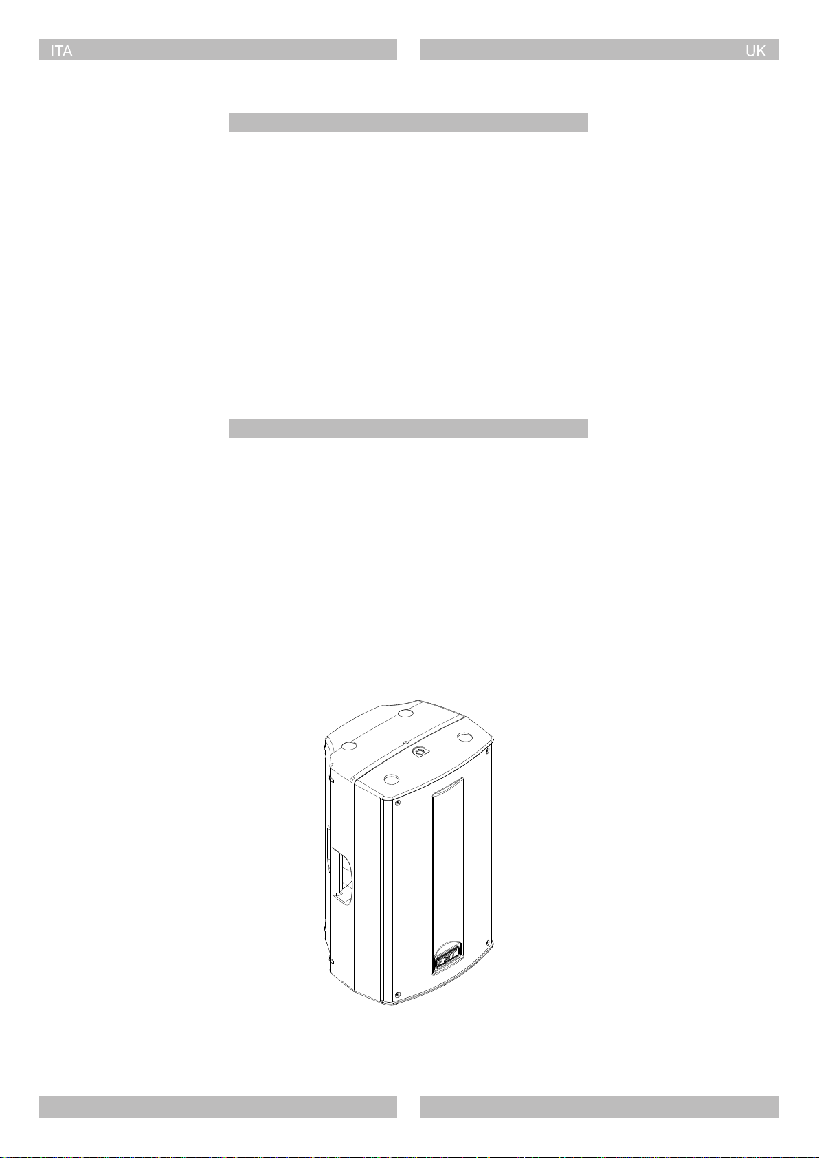
Con un cabinet in polipropilene appositamente sviluppato ed una
nuova elegante estetica, la nuova serie PROMAXX rappresenta
l'evoluzione di un classico.
Dotato di altoparlanti custom FBT e driver a compressione B&C,
PROMAXX è una combinazione di qualità e vero stile made in Italy.
Al suo interno un modulo amplificatore appositamente prodotto
dalla FBT con alimentatore switching; per le basse frequenze la
potenza è erogata da un amplificatore ad alta efficienza in Classe
D, che vanta una distorsione armonica totale estremamente bassa;
per le alte frequenze la potenza è garantita da una tipologia in
Classe H/AB che esalta le prestazioni audio nelle alte frequenze.
All'interno un processore di segnale digitale (DSP), dotato di una
interfaccia grafica intuitiva; situato sul pannello posteriore, il display
DSP visualizza tutte le scelte dal menu editabili tramite una sola
manopola con funzionalità "push-to-select".
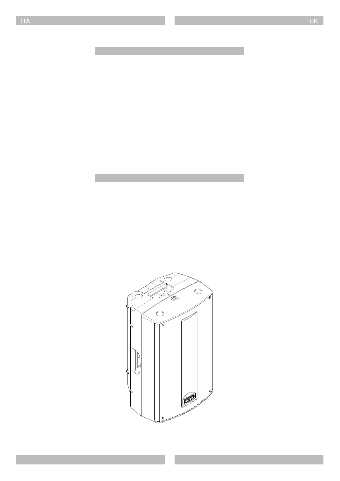
Il cabinet dispone di ben tre lati inclinati studiati per il
posizionamento stage monitor.
La leggerezza e la robustezza del diffusore consentono una grande
versatilità di utilizzo, con predisposizione per montaggio su stativo,
appeso a parete, in sospensione o l'implementazione di un array.
Versione attiva
Active version
114A
With a specifically designed polypropylene cabinet and a new,
elegant aesthetic appearance, the new PROMAXX series is an
evolution of a classic.
Equipped with a custom FBT speaker and B&C compression driver,
PROMAXX is a combination of quality and style made in Italy. It is
internally equipped with an amplifier module specifically
manufactured by FBT with switching power supply. Power is
supplied by a high efficiency Class D amplifier for low frequencies,
which has a very low total harmonic distortion. Instead, the power
supplied for high frequencies is ensured by a type Class H/AB,
which enhances audio performance at high frequencies. A digital
signal processor (DSP) is fitted inside and equipped with an intuitive
graphical interface; situated on the rear panel, the DSP display
shows all the menu choices, which can be edited via a single knob
with push-to-select features.
The cabinet has three sloped sides designed for stage monitor
positioning.
The lightweight but sturdy speaker makes it highly versatile, with
provision for mounting on a stand, wall-mounting, suspended, or
use of an array.
Versione passiva
Passive version
ProMaxX 110
114
112A
110A
MASTER VOL
DSP
CONTROLLER
PUSH FOR MENU
LINK IN
MIX OUT
OUTPUT
0
LINE / MIC IN
VOL
+36dB mic
0
STEREO IN
ProMaxX 110A
P R O C E S S E D A C T I V E S P E A K E R
TO PREVENT RISK OF FIRE OR ELECTRIC SHOCK
DO NOT REMOVE COVER ( OR BACK )
NO USER-SERVICEABLE PARTS INSIDE.
REFER SERVICING TO QUALIFIED PERSONNEL.
THIS APPARATUS MUST BE EARTHED
NEVER EXPOSE THIS EQUIPMENT TO RAIN OR MOISTURE
MADE IN ITALY
Power Consumption 600VA
REPLACE FUSES WITH SAME TYPE AND RATING.
112
110
VOL
+10dB+6dB line
L
R
LF
PRT
PRT
HF
CAUTION:
IT IS IMPORTANT TO USE AN AMPLIFIER THAT DOES NOT
EXCEED 300W RMS @8 OHMS.
TECHNICAL SPECIFICATIONS
Nominal Impedance :
Recommended Amplifier
Short Term Power :
Long Term Power :
Frequency Response (@-6dB):
Sensitivity @1W,1m :
Max SPL cont. / peak :
Dispersion :
+
1
1- 1-
2- 2-
2+ 2+
+
1
LINK
300 W RMS
60 Hz - 18 kHZ
122 / 127 dB
90˚H x 60˚V
IN
8 Ohm
600 W
150 W
97 dB
220 - 230V
50/60Hz
T4A L - 250V
FBT elettronica spa - RECANATI (MC) MADE IN ITALY
2
Page 6
CARATTERISTICHE
CARATTERISTICHE
110A
FEATURES
FEATURES
PROCESSED ACTIVE SPEAKER
- 700W + 200W RMS
- Woofer custom 250mm con bobina da 50mm
- Driver B&C con bocca da 25mm e bobina da 36mm
- Risposta in frequenza da 58Hz a 20kHz
- Dispersione 90°H x 60°V
- Staffa per installazione a muro (opzionale)
- Supporto per stativo da 35mm
- Maniglia integrata
- Cabinet in polipropilene
- Estetica "full-grille" con tessuto acustico
PASSIVE REINFORCEMENT SPEAKER
- 300W / 8 Ohm
- Risposta in frequenza da 60Hz a 18kHz
- Crossover passivo interno con protezione soft trip su WF e TW
- Connettori Speakon NL-4 IN & LINK out
PROCESSED ACTIVE SPEAKER
- 700W + 200W RMS
- 10" LF woofer with 2" voice coil
- 1" exit throat B&C HF compression driver with 1.4" voice coil
- Frequency response from 58Hz to 20kHz
- 90°H x 60°V dispersion
- Wall bracket mount thread(optional)
- 1.38" top-heat
- Integrated handle
- Polypropylene molded enclosure
- "full-grille" design with black acoustic cloth
110
PASSIVE REINFORCEMENT SPEAKER
- 300W / 8 Ohm
- Frequency response from 60Hz to 18kHz
- Built-in passive crossover with soft-trip protection for the WF & TW
- Speakon NL-4 IN & LINK out connectors
3
Page 7
CARATTERISTICHE
FEATURES
112A
PROCESSED ACTIVE SPEAKER
- 700W + 200W RMS
- Woofer custom 320mm con bobina da 64mm
- Driver B&C con bocca da 25mm e bobina da 36mm
- Risposta in frequenza da 48Hz a 20kHz
- Dispersione 90°H x 60°V
- Staffa per installazione a muro (opzionale)
- Supporto per stativo da 35mm
- Due maniglie integrate
- Cabinet in polipropilene
- Estetica "full-grille" con tessuto acustico
PASSIVE REINFORCEMENT SPEAKER
- 400W / 8 Ohm
- Risposta in frequenza da 55Hz a 18kHz
- Crossover passivo interno con protezione soft trip su WF e TW
- Connettori Speakon NL-4 IN & LINK out
PROCESSED ACTIVE SPEAKER
- 700W + 200W RMS
- 12" LF woofer with 2.5" voice coil
- 1" exit throat B&C HF compression driver with 1.4" voice coil
- Frequency response from 48Hz to 20kHz
- 90°H x 60°V dispersion
- Wall bracket mount thread(optional)
- 1.38" top-heat
- Two integrated handles
- Polypropylene molded enclosure
- "full-grille" design with black acoustic cloth
112
PASSIVE REINFORCEMENT SPEAKER
- 400W / 8 Ohm
- Frequency response from 55Hz to 18kHz
- Built-in passive crossover with soft-trip protection for the WF & TW
- Speakon NL-4 IN & LINK out connectors
4
Page 8

CARATTERISTICHE
FEATURES
114A
PROCESSED ACTIVE SPEAKER
- 700W + 200W RMS
- Woofer custom 355mm con bobina da 75mm
- Driver B&C con bocca da 35mm e bobina da 64mm
- Risposta in frequenza da 45Hz a 20kHz
- Dispersione 90°H x 60°V
- Staffa per installazione a muro (opzionale)
- Supporto per stativo da 35mm
- Due maniglie integrate
- Cabinet in polipropilene
- Estetica "full-grille" con tessuto acustico
PASSIVE REINFORCEMENT SPEAKER
- 700W / 8 Ohm
- Risposta in frequenza da 50Hz a 18kHz
- Crossover passivo interno con protezione soft trip su WF e TW
- Connettori Speakon NL-4 IN & LINK out
PROCESSED ACTIVE SPEAKER
- 700W + 200W RMS
- 14" LF woofer with 3" voice coil
- 1.4" exit throat B&C HF compression driver with 2.5" voice coil
- Frequency response from 45Hz to 20kHz
- 90°H x 60°V dispersion
- Wall bracket mount thread(optional)
- 1.38" top-heat
- Two integrated handles
- Polypropylene molded enclosure
- "full-grille" design with black acoustic cloth
114
PASSIVE REINFORCEMENT SPEAKER
- 700W / 8 Ohm
- Frequency response from 50Hz to 18kHz
- Built-in passive crossover with soft-trip protection for the WF & TW
- Speakon NL-4 IN & LINK out connectors
5
Page 9
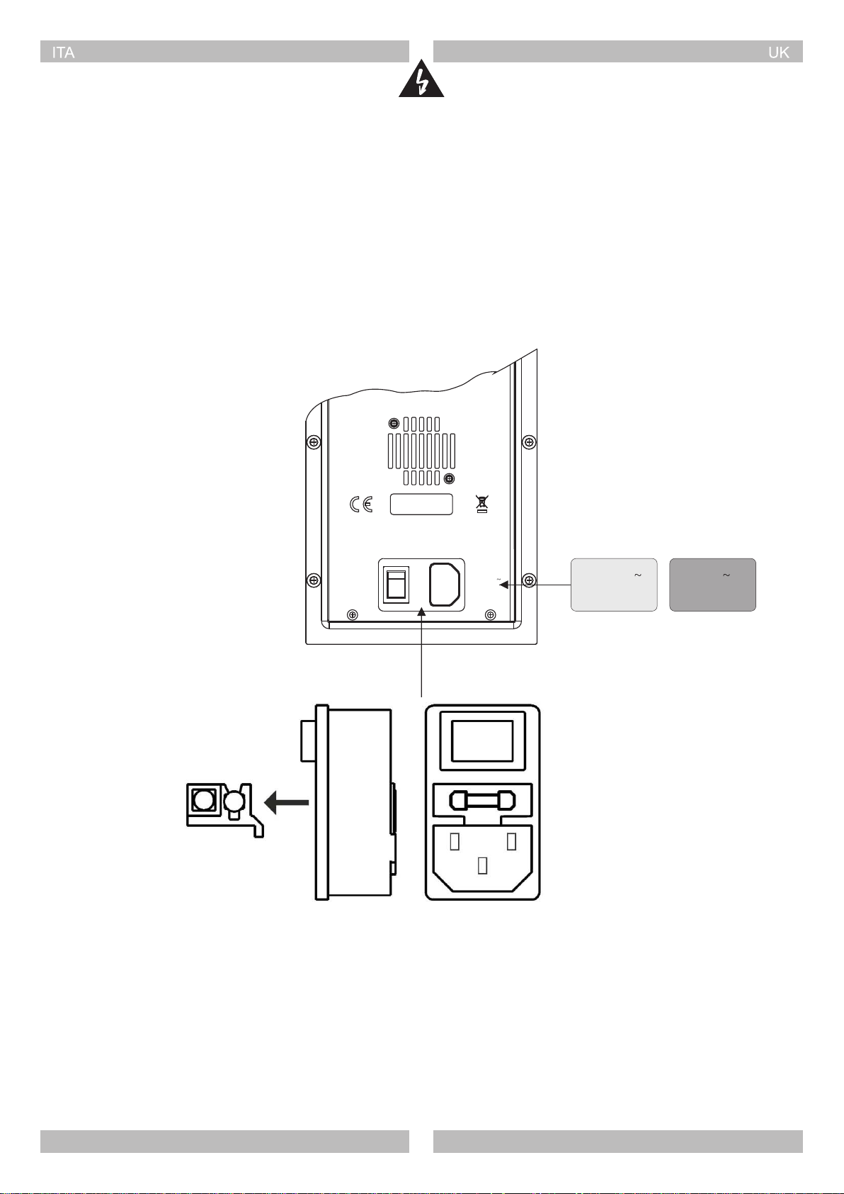
ALIMENTAZIONE
POWER SUPPLY
Prima di collegare l'apparecchio alla rete elettrica accertarsi che la
tensione di alimentazione corrisponda a quella indicata nel retro del
diffusore. La presa di alimentazione comprende anche un vano
portafusibile.
I fusibili difettosi devono essere sostituiti assolutamente con altri
che abbiano valore e caratteristiche elettriche uguali.
Power Consumption 600VA
REPLACE FUSES WITH SAME TYPE AND RATING.
Before connecting the apparatus to the mains make sure the supply
voltage matches the one indicated on the back of the apparatus.
The power socket also includes a fuse box.
Faulty fuses shall be replaced only with fuses having the same
electrical features and value.
MADE IN ITALY
220 - 230V
50/60Hz
T4A L - 250V
220 - 230V
50/60Hz
T4A L - 250V
120V
60Hz
T10A H - 250V
6
Page 10

CONNETTORI
CONNECTORS
CAVI DI COLLEGAMENTO
CONNECTION CABLES
7
Page 11

INSTALLAZIONE
PROMAXX PROMAXX
PROMAXX
INSTALLATION
PROMAXX
PROMAXX
PROMAXX
PROMAXX PROMAXX
8
Page 12

ACCESSORI
BOX 127 (ProMaxx110)
ACCESSORIES
PROMAXX PROMAXX
BOX 128 (ProMaxx112/114)
9
Page 13

MODALITÀ DI INSTALLAZIONE
INSTALLATION MODES
I diffusori della serie PROMAXX possono essere installati nei
seguenti modi:
- Sospensione mediante staffa a muro
- Installazione su supporto stativo
- Semplice posizionamento a stack con subwoofer a terra e satellite
corrispondente appoggiato su di esso
SOSPENSIONE MEDIANTE STAFFA A MURO
- Selezionare con cura l'area dove installare i diffusori e assicurarsi
che la struttura sia adeguata a supportare il peso del sistema
- Togliere i piedini in gomma di appoggio del diffusore
- Fissare la staffa al muro utilizzando appropriate viti su tutti i fori di
fissaggio della stessa
- Posizionare il diffusore tra i due bracci della staffa e fissarlo
utilizzando i due inserti filettati M10
- Orientare il diffusore nella posizione desiderata e bloccarlo tramite
il perno M6
PROMAXX speakers can be installed as follow:
- Suspension by wall bracket
- Installation on tripod stand
- Simple stack installation with the subwoofer on the ground
SUSPENSION BY WALL BRACKET
- Carefully choose speakers place of installation and make sure that
the structure can bear box weight
- Remove speaker's feet
- Secure the bracket to the wall by using screws in all its fixing holes
- Place the speaker between bracket arms and secure it through
two M10 threaded inserts
- Point the speaker as desired and lock it through the M6 pin
Piedini in gomma
Speaker's feet
INSTALLAZIONE SU SUPPORTO STATIVO
Con questo accorgimento si ha il vantaggio di avere le sorgenti
medio-alte più allineate con la posizione dell'orecchio
dell'ascoltatore.
- Accertarsi che lo stativo supporti il peso del diffusore
- Posizionare lo stativo su una superficie piana e non
sdrucciolevole.
- Per rendere più stabile lo stativo allargare al massimo la sua base.
INSTALLATION ON TRIPOD STAND
Such installation will allow medium-high frequency sources to the
better aligned to listener's ear.
- Make sure that the stand can bear speaker's weight
- Place the stand on a flat and antislip surface
- Widen stand base as much as possible to increase its stability.
10
Page 14

MODALITÀ DI INSTALLAZIONE
INSTALLATION MODES
POSIZIONAMENTO A STACK STACK INSTALLATION
Diffusori che devono essere trasportabili, riconfigurati su base
regolare o per realizzare impianti multipurpose, possono essere,
per comodità, essere impilati a terra.
- Verificare sempre la superficie di appoggio sulla quale va
collocato il sistema
- Ispezionate sempre la parte sottostante di qualsiasi struttura
temporanea per accertarvi che sia sufficientemente stabile e
robusta.
Speakers that must be transported, reconfigured on a regular basis
or to create multipurpose systems can be stacked on the ground for
convenience.
- Always check the support surface where the system is placed
- Always inspect the underlying part of any provisional structure to
make sure it is stable and sturdy enough.
11
Page 15

DIMENSIONI
110A - 110
DIMENSIONS
11.08" / 281.5mm
112A - 112
114A - 114
12.59" / 320mm
21.06" / 535mm
21.65" / 550mm
13.70" / 348mm 15.82" / 402mm
24.48" / 622mm
25.07" / 637mm
12° 40° 55°
12
Page 16

114A
112A
110A
1
3
6
7
CONTROLLI E FUNZIONI
Versione attiva
Active version
MASTER VOL
DSP
CONTROLLER
PUSH FOR MENU
0
LINK IN
MIX OUT
OUTPUT
VOL
+36dB mic
LINE / MIC IN
ProMaxX 114A
P R O C E S S E D A C T I V E S P E A K E R
0
STEREO IN
VOL
+10dB+6dB line
L
R
CONTROLS AND FUNCTIONS
Versione passiva
Passive version
114
112
ProMaxX 114
2
4
5
8
IN
+
LF
PRT
PRT
HF
1
1- 1-
2- 2-
2+ 2+
+
1
110
9
TO PREVENT RISK OF FIRE OR ELECTRIC SHOCK
DO NOT REMOVE COVER ( OR BACK )
NO USER-SERVICEABLE PARTS INSIDE.
REFER SERVICING TO QUALIFIED PERSONNEL.
THIS APPARATUS MUST BE EARTHED
NEVER EXPOSE THIS EQUIPMENT TO RAIN OR MOISTURE
MADE IN ITALY
Power Consumption 600VA
REPLACE FUSES WITH SAME TYPE AND RATING.
220 - 230V
50/60Hz
T4A L - 250V
1. Visualizzazione menu e impostazioni del DSP.
2. Volume digitale generale per il controllo del livello dei segnali
miscelati. Premere per entrare nel menu del DSP e ruotare la
manopola per la scelta e la selezione dei parametri.
3. Selettore per la modalità del segnale di uscita tra il "link" fisico
dell'ingresso XLR o la miscelazione dei due canali di ingresso
(post-volume).
4. Volume dell'ingresso stereo.
5. Volume dell'ingresso linea / microfono .
6. Presa XLR per l'invio del segnale verso un'altro diffusore.
7. Ingresso combo bilanciato per il collegamento di sorgenti linea o
microfoniche (la selezione avviene tramite impostazioni nel
menu).
8. Ingresso RCA per il collegamento di sorgenti esterne come ad
esempio MP3 player
9. Prese Speakon collegate in parallelo; utilizzare una presa per il
collegamento del diffusore all'uscita di un amplificatore di
potenza, l'altra per collegare un secondo diffusore.
LINK
CAUTION:
IT IS IMPORTANT TO USE AN AMPLIFIER THAT DOES NOT
EXCEED 700W RMS @8 OHMS.
TECHNICAL SPECIFICATIONS
Nominal Impedance :
Recommended Amplifier
Short Term Power :
Long Term Power :
Frequency Response (@-6dB):
Sensitivity @1W,1m :
Max SPL cont. / peak :
Dispersion :
FBT elettronica spa - RECANATI (MC) MADE IN ITALY
8 Ohm
700 W RMS
1400 W
350 W
50 Hz - 18 kHZ
100 dB
128 / 132 dB
90˚H x 60˚V
9
1. Menu display and DSP settings
2. General digital volume to control the level of mixed signals. Press
to access the DSP menu and turn the knob to select parameters.
3. Output signal mode selector between the physical link of input
XLR or a mixture of the two input channels (post-volume).
4. Stereo input volume.
5. Line/microphone input volume.
6. XLR outlet to send the signal to another speaker.
7. Combo balanced input to connect the line or microphone sources
(selection is made from the menu settings).
8. RCA input to connect external sources, for example an MP3
player
9. Speakon outlets connected in parallel. Use one outlet to connect
the speaker to the output of a power amplifier, and the other one
to connect a second speaker.
13
Page 17

DSP
DSP
DESCRIZIONE DEL MENU
1 2 3 4
ORIG/LIVE EQ POLE
LINE
5
DLY
6
0dB
PEAK REDUCTION LIMIT
10 11 12
MENU DESCRIPTION
7
8
9
FAN
Fig. 1: pag. iniziale
Fig. 1: first page
Stato del sistema Normal system status
1. PRESET - Impostazioni del preset
2. EQUALIZZAZIONE - Di default tutti i guadagni dei filtri sono
impostati a zero; l'indicazione EQ sta a significare, invece, che i
valori dell'equalizzazione sono stati impostati.
3. VOLUME - Guadagno generale del sistema; può variare da 0dB
a MUTE a passi di 1dB.
4. POSIZIONAMENTO - Impostazioni della "location".
5. SENSIBILITÀ DI INGRESSO - Impostazione per le funzioni MIC
o LINE
6. DELAY - Indica la presenza di ritardo applicato al segnale di
ingresso; di default il ritardo è pari a 0mS.
7. PRESENZA DI SEGNALE.
8. FILTRO PASSA ALTO - Indica la presenza del filtro passa-alto
impostato; di default è impostato in modalità by-pass.
1. PRESET - Preset settings
2. EQUALISATION - By default, all filter gains are set to zero. On the
other hand, the signal EQ means that the equalisation values are
set.
3. VOLUME - General system level; it can range from 0dB to MUTE
at steps of 1dB.
4. POSITIONING - Location setting.
5. INPUT SENSITIVITY - Setting for the MIC or LINE functions
6. DELAY - Indicates the delay applied to the input signal; the
default delay is 0mS.
7. SIGNAL PRESENCE.
8. HIGH-PASS FILTER - Indicates the presence of the high-pass
filter set; Default is set to bypass mode.
Indicatori di protezione System protection
9. FAN - Segnala un possibile guasto alla ventola di raffreddamento
10. PEAK - Indicazione di picco sul segnale in ingresso
11. RIDUZIONE DEL GUADAGNO - Indica la riduzione del
guadagno come protezione da sovratemperatura.
12. LIMIT - Indica l'attivazione del limitatore.
9. FAN - Signals a possible fault of the cooling fan
10. PEAK - Indicates the peak input signal
11. GAIN DECREASE - Indicates a reduction in the gain as
protection against over-temperature.
12. LIMIT - Indicates enabling of the limiter.
Indicatori di guasto Fault controls
AMPLIFIER
PROTECT
In caso di malfunzionamento il display fornisce indicazioni della
possibile causa, discernendo tra cause termiche segnalate come
THERMAL PROTECT, o guasti generici dell'amplificatore segnalati
come AMPLIFIER PROTECT.
In case of malfunction, the display provides information regarding
the possible cause, distinguishing between thermal causes marked
as THERMAL PROTECT, or general amplifier faults reported as
AMPLIFIER PROTECT.
Fig. 2: indicatori di guasto
Fig. 2: fault indicators
14
Page 18

DSP
DSP
CONTROLLO DEI PARAMETRI DI SISTEMA SYSTEM PARAMETERS CONTROL
TUTTE LE MODIFICHE APPORTATE AI PARAMETRI DEL
SISTEMA VERRANNO SALVATE NELLA MEMORIA INTERNA
DOPO CIRCA 10 SECONDI DI INATTIVITÀ; NEL CASO CHE IL
DIFFUSORE VENISSE SPENTO PRIMA DI TALE INTERVALLO, I
PARAMETRI MODIFICATI NON VERRANNO MEMORIZZATI.
Per accedere alle funzionalità di controllo dei parametri del sistema
occorre agire sulla manopola MASTER VOL.
1. Premere la manopola MASTER VOL per accedere al menu;
viene selezionata la voce principale, situata nella colonna
sinistra del menu.
2. Ricercare la voce di menu richiesta ruotando la manopola.
3. Premere la manopola per selezionare la voce che si vuole
modificare; viene visualizzata la voce del sottomenu nella
colonna destra ( in alcune voci può apparire una nuova finestra di
menu se le possibilità di modifica riguardano un maggior numero
di variabili, come nel caso dell'equalizzatore a tre bande).
ALL CHANGES MADE TO THE SYSTEM PARAMETERS WILL
BE S AV E D I N T H E I N TERN A L MEM O RY A F T E R
APPROXIMATELY 10 SECONDS OF INACTIVITY; IF THE
SPEAKER IS SWITCHED OFF BEFORE THAT TIME, THE
PARAMETER CHANGES WILL NOT BE SAVED.
To access the system's parameters control function, you must turn
the MASTER VOL. knob.
1- Press the MASTER VOL knob to access the menu. The main
item situated in the left column of the menu will be selected.
2. Search for the menu item requested by turning the knob.
3. Press the knob to select the item you want to edit. The sub-menu
item will be displayed in the right column (certain items may open
a new menu window if the editing options concern a higher
number of variables, as in the case of the three-band equaliser).
EXIT
PRESET:
ORIG/LIVE
LOCATION: POLE
HI-PASS: BYPASS
4. Ricercare la voce desiderata ruotando la manopola.
5. Premere per confermare la scelta ed applicare le modifiche
richieste. Nel caso di possibili modifiche a più variabili (es. filtri
USER o equalizzatore a tre bande), ripetere i passi dal 2 al 5 ,
oppure selezionare le voci di salvataggio indicate a schermo. La
selezione torna sulle voci nella parte sinistra del menu; la
selezione viene salvata su memoria interna.
6. EXIT per tornare alla pagina iniziale.
Fig. 3: menu principale
Fig. 3: main menu
4. Search for the desired item by turning the knob.
5. Press to confirm the choice and apply the requested changes.
In case of possible changes with multiple variables (e.g. USER
filters or three-band equaliser), repeat steps 2-5, or select the
save items on the screen. Selection goes back to the items on the
left part of the menu; selection is saved on the internal memory.
6. EXIT to go back to the initial page.
15
Page 19

DSP
DSP
DESCRIZIONE DELLE VOCI DEL MENU PRINCIPALE
EXIT
Torna alla pagina iniziale. Il sistema è inoltre dotato di funzione di
ritorno automatico alla pagina iniziale dopo alcuni secondi di
inattività ( funzione valida solo per le voci situate nella colonna di
sinistra del menu principale).
PRESET
Funzione di configurazione della risposta del diffusore:
- ORIG/LIVE: preset di default per utilizzo general purpose, adatto
quindi alla maggior parte delle applicazioni.
- VOCAL: permette di avere la massima intelligibilità del parlato
anche in ambienti difficili o con elevato "noise floor"; la banda
passante viene modificata per esaltare la gamma vocale.
- DJ: preset studiato per applicazioni DJ, con bassi molto potenti ed
acuti mai fastidiosi.
- TOURING: risposta neutra e lineare in tutta la banda passante del
diffusore.
- LOUDNESS: tipica curva di risposta per applicazione musicale o
disco, con bassi ed acuti enfatizzati rispetto alle medie frequenze,
che rimangono leggermente arretrate. È un preset molto
piacevole da ascoltare a basso volume, ma adatto anche per
utilizzo del diffusore in discoteche o pubs.
- WARM: dà un carattere corposo sui medio-bassi e meno
aggressivo sulla parte acuta; adatto alla riproduzione di musica in
ambienti molto assorbenti o nelle situazioni dove è richiesto un
suono molto energico alle basse frequenze e dolce alle medioalte.
- USER 1 & USER 2: preset impostabili dall'utente; la pressione
della manopola permette di selezionare il preset e di modificarlo
(voci di SEL e EDIT).
DESCRIPTION OF THE MAIN MENU ITEMS
Go back to the initial page. The system is also equipped with an
automatic return function to the initial page after a few seconds of
inactivity (the function is only valid for items situated in the left
column of the main menu).
Speaker response configuration function:
- ORIG/LIVE: default setting for general purpose use, therefore,
suitable for most applications.
- VOCAL: enables maximum speech intelligibility, also in difficult
environments or with high noise floor; the b a n d w i d t h i s
modified to enhance the vocal range.
- DJ: preset designed for DJ applications, with very powerful bass
and no annoying treble.
- TOURING: neutral and linear response in the entire bandwidth of
the speaker
- LOUDNESS: typical response curve for music or disco, with bass
and treble emphasised compared to medium frequencies,
which remain slightly back. It is a very pleasant preset to listen to
at low volume, but it is also suitable to use the speaker in discos
and pubs.
- WARM: it gives a medium-low and less aggressive body on the
treble. It is suitable for music reproduction in very absorbing
environments or in situations that require energetic sound at low
frequencies and soft at medium-high.
- USER 1 & USER 2: preset that can be set by the user; pressing
the knob enables you to select the preset and edit it (SEL and
EDIT items).
EXIT
PRESET:
USER 1
LOCATION: POLE
HI-PASS: BYPASS
Selezionando EDIT si apre una nuova finestra in cui, ad uno ad uno,
vengono illustrati tutti i filtri IIR del secondo ordine e le loro variabili,
insieme alla voce BACK per tornare alla pagina precedente. Per
modificare i parametri dei singoli filtri, scegliere quello desiderato e
selezionarlo premendo la manopola (2 - MASTER VOL); a questo
punto si potranno selezionare il tipo di filtro ( PARAMETRIC, LOW
SHELF, HI SHELF, LPF 12dB/oct, HPF 12dB/oct ), una ad una le
variabili del filtro (frequenza, fattore Q, guadagno), oltre alle voci di
RESET, che riporta il filtro in modalità bypass e SAVE che
memorizza i cambiamenti effettuati. Le modifiche dei filtri verranno
effettuate in base a valori prefissati:
- FREQUENZA - frequenze di centro banda a 1/12 di ottava
- Q - variabile da 0.2 a 10, con incrementi di 0.2
- GAIN - variabile da -10 a +10, con incrementi di 0.5
Una volta impostati tutti i filtri desiderati,
la selezione della voce BACK applica i
cambiamenti al DSP e memorizza i dati
su EEPROM.
FILTER 1: PARAMETRIC
FREQ:
Q: 1.0
BACK
SEL
EDIT
Fig. 4: preset USER ( selezione e modifica)
Fig. 4: preset USER ( select and edit)
Selecting EDIT opens a new window in which all the second order
IIR filters and their variables are displayed one by one, together with
BACK to go back to the previous page. To edit the parameters of
individual filters, select the desired one and select it by pressing the
knob (2 - MASTER VOL). You can now select the type of filter
(PARAMETRIC, LOW SHELF, HI SHELF, LPF 12dB/oct, HPF
12dB/oct ) and the variables of the filter one by one (frequency, Qfactor, gain), as well as RESET items, which shows the filter in
bypass mode and SAVE that stores the changes made. The filter
changes will be carried out according to pre-set values:
- FREQUENZA - frequenze di centro banda a 1/12 di ottava
- Q - variabile da 0.2 a 10, con incrementi di 0.2
- GAIN - variabile da -10 a +10, con incrementi di 0.5
Once all the desired filters have been
set, select BACK to apply the changes
1250Hz
1000Hz
to the DSP and store data on EEPROM.
GAIN: +0.0dB
Fig. 5: modifica dei parametri dei filtri del preset USER
Fig. 5: edit the filters' parametric values of the preset USER
16
Page 20

DSP
DSP
DESCRIZIONE DELLE VOCI DEL MENU PRINCIPALE
LOCATION
Funzione di ottimizzazione della risposta del diffusore in base alla
disposizione del sistema:
- POLE: diffusore posizionato su stativo o treppiede (valore di
default)
- MONITOR: diffusore posizionato in modalità monitor; tale
settaggio compensa il "boost" (spinta) alle basse frequenze
prodotto dal diffusore a contatto col pavimento
- WALL: diffusore montato a parete; anche qui viene compensato il
"boost" alle basse frequenze derivante dal contatto con il muro
- ARRAY: diffusore installato fianco a fianco con altri diffusori dello
stesso tipo, in cluster o array; viene compensato l'effetto derivante
dal piazzamento di più diffusori a stretto contatto.
HI-PASS
Funzione di selezione della frequenza del filtro passa alto in
ingresso, utile se il diffusore è accoppiato ad un subwoofer. Le
opzioni disponibili sono:
- BYPASS (valore di default)
- FBT SUB - ottimizza l'allineamento del diffusore alla gamma di
subwoofer FBT. Le frequenze generiche disponibili vanno da 80Hz
a 140Hz (per i modelli 110,112,115) e da 100Hz a 150Hz per il
modello 206.
DESCRIPTION OF THE MAIN MENU ITEMS
Function to optimise the response of the speaker according to the
system's availability:
- POLE: speaker positioned on a support stand or tripod (default
value)
- MONITOR: speaker set to monitor mode; this setting
compensates the boost according to the low frequencies
generated by the speaker in contact with the ground
- WALL: wall-mounted speaker; also in this case, the boost is
compensated according to the low frequencies resulting from
contact with the wall
- ARRAY: speaker installed next to other speakers of the same
type, in cluster or array; the effect resulting from placing several
speakers in strict contact is compensated for.
High pass filter frequency input function selection, which is useful if
the speaker is coupled to a subwoofer. The options available are:
- BYPASS (default value)
- FBT SUB - optimises alignment of the speaker to the range of FBT
subwoofer. The general frequencies available range from 80Hz to
140Hz ( for 110, 112, 115 models ) and from 100Hz to 150Hz for
model 206.
3-BAND EQ
LOW:
MID:
HIGH
Funzione di regolazione dei guadagni dell'equalizzatore a 3 bande.
La selezione apre una nuova finestra in cui è possibile regolare i
guadagni dei 3 filtri di tono (Low, Mid, High), con voce di ritorno alla
pagina precedente (BACK). Di default i valori sono tutti impostati a
zero.
PEAK LIMITER
Il parametro può essere modificato solo se si è scelto uno dei due
USER PRESET.
Sono previsti tre modi di settaggio per il PEAK LIMITER del
diffusore: una limitazione blanda (MIN) per avere la massima
pressione sonora soprattutto alle basse frequenze pur tollerando
una lieve distorsione a volume molto alto; una normale (NORMAL);
una più decisa (MAX) che, a fronte di una piccola riduzione di SPL,
evita qualsiasi forma di distorsione anche nei transienti a volume
molto alti, adatta soprattutto per il parlato o riproduzione di
strumenti acustici.
+2.0dB
-1.0dB
+0.0dB
BACK
Gain adjustment function of the 3-band equaliser. The selection
opens a new window where you can adjust the gains of the three
tone filters (Low, Mid, High), with item to go back to the previous
page (BACK). The default values are all set to zero.
The parameter can only be edited if one of the USER PRESET is
selected.
There are three setting methods for the speaker's PEAK LIMITER:
a mild limitation (MIN) in order to have maximum sound pressure,
especially at low frequencies despite tolerating slight distortion with
very high volume; a normal (NORMAL); a more decisive (MAX)
which, with a slight reduction in SPL, avoids any form of distortion
even with very high transient volume, specifically suitable for
speech and reproduction of acoustic instruments.
Fig. 6: equalizzatore a 3 bande
Fig. 6: 3-band equaliser
17
Page 21

DSP
DSP
DESCRIZIONE DELLE VOCI DEL MENU PRINCIPALE
MIC - LINE
Funzione di selezione della sensibilità di ingresso per funzioni linea
o microfono.
DELAY
Funzione di selezione del ritardo applicato al segnale di ingresso,
per allineare la fase ad altri diffusori posti nello stesso luogo. Il
valore del ritardo impostabile va da zero a 10 metri, con incrementi
da 0.25 metri; il valore del ritardo è indicato in mS e in metri.
SERVICE
Menu di servizio per analizzare il funzionamento del diffusore.
- NORMAL - entrambi i canali sono attivi.
- LF OFF - canale delle basse frequenze in mute; utile per
analizzare il funzionamento del solo canale delle alte frequenze.
- HF OFF - canale delle alte frequenze in mute; utile per analizzare il
funzionamento del solo canale delle basse frequenze.
- SENSORS - la selezione apre una nuova finestra con i valori delle
temperature dei sensori interni ( AIR, CHASSIS), più una voce di
ritorno al menu principale (BACK).
DESCRIPTION OF THE MAIN MENU ITEMS
Line or microphone functions input sensitivity selection function.
Function to select the delay time applied to the input signal to align
the phase with other speakers placed in the same room. The delay
value can be set from zero to 10 metres, with increases of 0.25
metres. The delay value is indicated in mS and metres.
Service menu to analyse speak operation.
- NORMAL - both channels are active.
- LF OFF - low frequency channel in mute; useful to analyse
operation of the high frequency channel only.
- HF OFF - high frequency channel in mute; useful to analyse
operation of the low frequency channel only.
- SENSORS - selection opens a new window with the temperature
values of the internal sensors (AIR, CHASSIS), including an item
to go back to the main menu (BACK).
TEMPERATURES
CHASSIS
AIR
LOCK SCREEN
Funzione di blocco del menu, che impedisce di modificare
accidentalmente le impostazioni del DSP. La selezione apre una
nuova finestra in cui scegliere se abilitare il LOCK, con le istruzioni
per lo sblocco ( tali istruzioni, in modalità LOCKED, verranno
indicate a schermo ad ogni tentativo di accesso, per mezzo della
manopola MASTER VOL.
ARE YOU SURE ?
YES NO
TO UNLOCK THE MENU PRESS AND HOLD
THE MENU BUTTON FOR 5 SECONDS
36°C
35°C
BACK
Menu lock function, which prevents accidental changes to settings
of DSP. Selection opens a new window where you can select if you
want to enable LOCK, with the instructions for release (these
instructions, in LOCKED mode, will be displayed on the screen
each time you attempt access from the MASTER VOL. knob
Fig. 7: vista dei sensori di temperatura
Fig. 7: view of the temperature sensors
Fig. 8: finestra di blocco schermo
Fig. 8: lock screen window
18
Page 22

DSP
DSP
DESCRIZIONE DELLE VOCI DEL MENU PRINCIPALE
CONTRAST
Funzione di regolazione del contrasto del display; il range va da -10
a +10
BACKLIGHT
Seleziona la modalità di funzionamento della retroilluminazione del
display.
- ON - luminosità sempre al massimo
- OFF - spegne la retroilluminazione
RESET
Funzione di ripristino ai dati di fabbrica (cancellazione di tutte le
personalizzazioni effettuate dall'utente). La selezione apre una
nuova finestra in cui viene chiesta conferma per l'esecuzione del
RESET.
DESCRIPTION OF THE MAIN MENU ITEMS
Function to adjust contrast of the display; ranging from -10 to +10
Select the display's backlighting
- ON - always maximum luminosity
- OFF - switches off backlighting
Function to reset default settings (delete all customised settings
made by the user). Selection opens a new window where you will be
asked to confirm execution of RESET.
RESET TO
FACTORY SETTINGS ?
INFO
Fornisce le informazioni generiche sul diffusore (nome, versione,
firmware, ecc.).
BACKYES
Provides general information regarding the speaker (name,
version, firmware, etc.)
Fig. 9: ripristino ai dati di fabbrica
Fig. 9: restore default settings
19
Page 23

ESEMPI DI CONFIGURAZIONI
CONFIGURATION EXAMPLES
MASTER VOL
DSP
CONTROLLER
PUSH FOR MENU
0
STEREO IN
OUTPUT
0
LINE / MIC IN
VOL
+36dB mic
ProMaxX 114A
P R O C E S S E D A C T I V E S P E A K E R
TO PREVENT RISK OF FIRE OR ELECTRIC SHOCK
DO NOT REMOVE COVER ( OR BACK )
NO USER-SERVICEABLE PARTS INSIDE.
REFER SERVICING TO QUALIFIED PERSONNEL.
THIS APPARATUS MUST BE EARTHED
NEVER EXPOSE THIS EQUIPMENT TO RAIN OR MOISTURE
MASTER VOL
DSP
CONTROLLER
PUSH FOR MENU
VOL
+10dB+6dB line
L
R
LINK IN
MIX OUT
OUTPUT
0
LINE / MIC IN
VOL
+36dB mic
0
STEREO IN
VOL
+10dB+6dB line
L
R
ProMaxX 114A
P R O C E S S E D A C T I V E S P E A K E R
TO PREVENT RISK OF FIRE OR ELECTRIC SHOCK
DO NOT REMOVE COVER ( OR BACK )
NO USER-SERVICEABLE PARTS INSIDE.
REFER SERVICING TO QUALIFIED PERSONNEL.
THIS APPARATUS MUST BE EARTHED
NEVER EXPOSE THIS EQUIPMENT TO RAIN OR MOISTURE
MADE IN ITALY
Power Consumption 600VA
REPLACE FUSES WITH SAME TYPE AND RATING.
220 - 230V
50/60Hz
T4A L - 250V
- Dal menu nella impostazione MIC/LINE selezionare MIC.
- Sul pannello di controllo posizionare l'interruttore nella posizione
MIX OUT.
MADE IN ITALY
Power Consumption 600VA
REPLACE FUSES WITH SAME TYPE AND RATING.
- Select MIC from the MIC/LINE settings menu.
- From the control panel, set the switch to MIX OUT.
20
220 - 230V
50/60Hz
T4A L - 250V
Page 24

ESEMPI DI CONFIGURAZIONI
CONFIGURATION EXAMPLES
MASTER VOL
DSP
CONTROLLER
PUSH FOR MENU
LINK IN
MIX OUT
OUTPUT
0
LINE / MIC IN
VOL
+36dB mic
0
STEREO IN
ProMaxX 114A
P R O C E S S E D A C T I V E S P E A K E R
TO PREVENT RISK OF FIRE OR ELECTRIC SHOCK
DO NOT REMOVE COVER ( OR BACK )
NO USER-SERVICEABLE PARTS INSIDE.
REFER SERVICING TO QUALIFIED PERSONNEL.
THIS APPARATUS MUST BE EARTHED
NEVER EXPOSE THIS EQUIPMENT TO RAIN OR MOISTURE
MASTER VOL
DSP
CONTROLLER
PUSH FOR MENU
VOL
+10dB+6dB line
L
R
Dal menu attivare la
modalità HIPASS
Enable HIPAA from
the menu
LINK IN
MIX OUT
OUTPUT
0
LINE / MIC IN
VOL
+36dB mic
0
STEREO IN
VOL
+10dB+6dB line
L
R
ProMaxX 114A
P R O C E S S E D A C T I V E S P E A K E R
TO PREVENT RISK OF FIRE OR ELECTRIC SHOCK
DO NOT REMOVE COVER ( OR BACK )
NO USER-SERVICEABLE PARTS INSIDE.
REFER SERVICING TO QUALIFIED PERSONNEL.
THIS APPARATUS MUST BE EARTHED
NEVER EXPOSE THIS EQUIPMENT TO RAIN OR MOISTURE
MADE IN ITALY
Power Consumption 600VA
REPLACE FUSES WITH SAME TYPE AND RATING.
220 - 230V
50/60Hz
T4A L - 250V
LINK
OUT
IN
LINK
OUT
IN
MADE IN ITALY
Power Consumption 600VA
REPLACE FUSES WITH SAME TYPE AND RATING.
SUBWOOFER SUBWOOFER
220 - 230V
50/60Hz
T4A L - 250V
21
Page 25

ESEMPI DI CONFIGURAZIONI
ProMaxX 114
IN
CONFIGURATION EXAMPLES
LF
PRT
PRT
HF
CAUTION:
IT IS IMPORTANT TO USE AN AMPLIFIER THAT DOES
NOT EXCEED 700W RMS @8 OHMS.
TECHNICAL SPECIFICATIONS
Nominal Impedance :
Recommended Amplifier
Short Term Power :
Long Term Power :
Frequency Response (@-6dB):
Sensitivity @1W,1m :
Max SPL cont. / peak :
FBT elettronica spa - RECANATI (MC) MADE IN ITALY
+1+
1- 1-
2- 2-
2+ 2+
1
LINK
8 Ohm
700 W RMS
1400 W
350 W
50 Hz - 18 kHZ
100 dB
128 / 132 dB
LINK
UNITÀ DI POTENZA
POWER AMP
CH2 INCH1 OUTCH2 OUT
CH1 IN
SUBWOOFER
OUTPUTS
U
L
PROCESSORE
INPUTS
PROCESSOR
LEFT
MAIN OUT
MIXER
22
Page 26

CARATTERISTICHE TECNICHE
114A
700/200 700/200 700/200
1400/400 1400/400 1400/400
45Hz - 20kHz 48Hz - 20kHz 58Hz - 20kHz
1x355 / bobina 75
1x35 / bobina 64
127.5 / 135.5 126 / 133 124 / 131
90° x 60°
600 600 600
XLR con loop / RCA st. XLR con loop / RCA st. XLR con loop / RCA st.
402 x 637 x 348 320 x 550 x 281.5
17.5 14.8 10.3
488 x 735 x 427
112A 110A
90° x 60° 90° x 60°
402 x 637 x 348
488 x 735 x 427
390 x 635 x 342
20.1 17.8 12.8
114
700 300
350 150
1400 600
50Hz - 18kHz 55Hz - 18kHz 60Hz - 18kHz
1x355 / bobina 75
1x35 / bobina 64
100 97
128 / 132 125 / 129 122 / 127
90° x 60° 90° x 60° 90° x 60°
1.3
112 110
400
200
800
99
402 x 637 x 348 320 x 550 x 281.5
15 13.4 8.9
488 x 735 x 427
18
402 x 637 x 348
488 x 735 x 427
16.4
390 x 635 x 342
11.4
23
Page 27

TECHNICAL SPECIFICATIONS
114A
700/200 700/200 700/200
1400/400 1400/400 1400/400
45Hz - 20kHz 48Hz - 20kHz 58Hz - 20kHz
1x14 / coil 3
1.4 / coil 2.5
127.5 / 135.5 126 / 133 124 / 131
90° x 60°
600 600 600
XLR with loop / RCA st. XLR with loop / RCA st. XLR with loop / RCA st.
16.4 16.4 16.4
15.82 x 25.07 x 13.70 12.59 x 21.65 x 11.08
40.78 32.62 22.70
19.21 x 28.93 x 16.81
112A 110A
1x12 / coil 2.5 1x10 / coil 2
1 / coil 1.4 1 / coil 1.4
90° x 60° 90° x 60°
15.82 x 25.07 x 13.70
19.21 x 28.93 x 16.81
15.35 x 24.99 x 13.46
44.31 39.24 28.21
114
700 300
350 150
1400 600
50Hz - 18kHz 55Hz - 18kHz 60Hz - 18kHz
1x14 / coil 3
1.4 / coil 2.5
100 97
128 / 132 125 / 129 122 / 127
90° x 60° 90° x 60° 90° x 60°
1.3
112 110
400
200
800
1x12 / coil 2.5 1x10 / coil 2
1 / coil 1.4 1 / coil 1.4
99
15.82 x 25.07 x 13.70 12.59 x 21.65 x 11.08
33.06 29.54 19.62
19.21 x 28.93 x 16.81
39.68
15.82 x 25.07 x 13.70
19.21 x 28.93 x 16.81
36.15
15.35 x 24.99 x 13.46
25.13
24
Page 28

CODE 40905#28122016
 Loading...