

Page 1
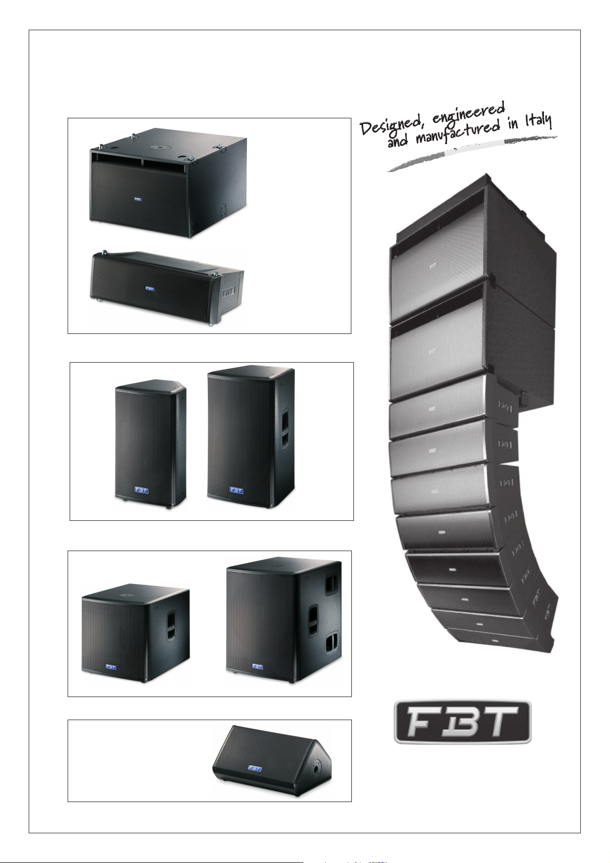
Sound Reinforcement
MITUS
212FSA / 212FS
Line Array System
206LA / 206L
Speaker Series
Speakers
Subwoofers
118SA / 118S 121SA / 121S
115A / 115112A / 112
Monitor
Stage
210MA / 210M
FBT Elettronica s.p.a.
Via Paolo Soprani 1
Zona Ind.le Squartabue
62019 RECANATI - ITALY
Tel. 071 750591 - Fax 071 7505920
e.mail: info@fbt.it - www.fbt.it
Page 2

Page 3

ITA
INDICE
INDEX
UK
ATTENZIONE-PRECAUZIONIA ----------------------------------------------------------------------------------------------------------------------
ATTENTION-PRECAUTIONSA
INTRODUZIONE---------------------------------------------------------------------------------------------------------------------------------------
INTRODUCTION
MODULO AMPLIFICATORE-----------------------------------------------------------------------------------------------------------------------AMPLIFIER MODULE
CARATTERISTICHE GENERALI------------------------------------------------------------------------------------------------------------
GENERAL FEATURES
206LA / 206L
212FSA / 212FS
210MA / 210M
112A / 112
115A / 115
121SA / 121S
118SA / 118S
CONTROLLI E FUNZIONI---------------------------------------------------------------------------------------------------------------
CONTROLS AND FUNCTIONS
206LA / 206L
212FSA / 212FS
210MA / 210M
112A / 115A - 112A / 115
TROMBA RUOTABILE/ (112/112A - 115/115A)--------------------------------------------------------------------ROTATABLE HORN
121SA / 118SA - 121S / 118S
3-4-5
6-7-8-9-11
1
2
2
10
PRESET------------------------------------------------------------------------------------------------------------------------------------
CONFIGURAZIONI CARDIOIDI------------------------------------------------------------------------------------------------------------------
CARDIOID CONFIGURATIONS
CONNETTORI-----------------------------------------------------------------------------------------------------------------------------------------
CONNECTORS
ALIMENTAZIONE---------------------------------------------------------------------------------------------------------------------------------
POWER SUPPLY
ESEMPI DI UTILIZZO--------------------------------------------------------------------------------------------------------------
USAGE EXAMPLES
DIMENSIONI----------------------------------------------------------------------------------------------------------------------------------
DIMENSIONS
IL SISTEMA LINE ARRAY----------------------------------------------------------------------------------------------------------------------------
THE LINE ARRAY SYSTEM
CONFIGURAZIONI CONSIGLIATE---------------------------------------------------------------------------------------------------------------
RECOMMENDED CONFIGURATIONS
ACCESSORI--------------------------------------------------------------------------------------------------------------------------------------------
ACCESSORIES
GUIDA AL MONTAGGIO DEL SISTEMA IN ARRAY VERTICALE-----------------------------------------------------
HOW TO ASSEMBLE THE SYSTEM IN A VERTICAL ARRAY
12-13-14-15
18-19
20-21-22-23-24
25-26-27
30-31-32-33-34-35
16
17
28
28
29
SPECIFICHE TECNICHE-----------------------------------------------------------------------------------------------------------------------
TECHNICAL SPECIFICATIONS
GLOSSARIO--------------------------------------------------------------------------------------------------------------------------------------
GLOSSARY
36-37
38-39
Page 4
ITA UK
WARNING
|
|
|
PER EVITARE IL RISCHIO DI SHOCK ELETTRICO
NON USARE UTENSILI MECCANICI ALL'INTERNO
CONTATTARE UN CENTRO DI ASSISTENZA QUALIFICATO
PER EVITARE IL RISCHIO DI INCENDIO O DI SHOCK ELETTRICO
NON ESPORRE L'APPARECCHIATURA ALLA PIOGGIA
QUESTO SIMBOLO AVVERTE, LADDOVE APPARE, LA PRESENZA DI UNA
TENSIONE PERICOLOSA NON ISOLATA ALL’INTERNO DELLA CASSA:
|
|
|
|
IL VOLTAGGIO P UÒ ESS ERE SUFFICIENT E PE R CO STI TUIRE
|
|
IL RISCHIO DI SCOSSA ELETTRICA.
<
<
QUESTO SIMBOLO AVVERTE, LADDOVE APPARE, DELLA
PRESENZA DI IMPORTANTI ISTRUZIONI PER L’USO E PER
LA M ANU TE NZ ION E NE LL A D OCU MENTA ZIO NE
!
!
ALLEGATA. SI PREGA DI CONSULTARE IL MANUALE.
RISCHIO DI SHOCK ELETTRICO
<
<
NON APRIRE IL COPERCHIO
NON APRIRE
O ALL'UMIDITA'
!
!
ATTENZIONE
ATTENZIONE
|
|
|
|
|
|
|
|
|
<
<
TO REDUCE THE RISK OF ELECTRIC SHOCK
DO NOT REMOVE COVER (OR BACK)
REFER SERVICING TO QUALIFIED SERVICE PERSONNEL
DO NOT EXPOSE THIS EQUIPMENT TO RAIN OR MOISTURE
NO USER SERVICEABLE PARTS INSIDE
TO REDUCE THE RISK OF FIRE OR ELECTRIC SHOCK
WHERE MARKED, THIS SYMBOL INDICATES A DANGEROUS NONISOLATEDVOLTAGEINSIDE THE LOUDSPEAKER:
|
|
|
|
SUCH VOLTAGE COULD BE SUFFICIENT TO RESULT IN THE RISK OF
|
|
ELECTRIC SHOCK.
<
<
WHERE MARKED, THIS SYMBOL INDICATES IMPORTANT
USAGE AND MAINTENANCE INSTRUCTIONS IN THE
ENCLOSED D OCUMENTS. PLEASE REFER TO THE
!
!
MANUAL.
WARNING
RISK OF ELECTRIC SHOCK
DO NOT OPEN
!
!
IMPORTANTI ISTRUZIONI DI SICUREZZA
IMPORTANTI ISTRUZIONI DI SICUREZZA
1) Leggere questeistruzioni
2) Conservare questeistruzioni
3) Fare attenzionea tutti gliavvertimenti
4) Seguire tuttele istruzioni
5) Non usarequesto dispositivo vicinoall’acqua
6) Pulire solocon uno strofinaccioasciutto
7) Non ostruire le aperture di ventilazione. L’installazione deve essere
eseguita in basealle istruzioni fornitedal produttore.
8) Non installare nelle vicinanze di fonti di calore come termosifoni,
valvole di regolazione, stufe oaltri apparecchi ( amplificatori compresi)
che producono calore
9) Non annullare l’obiettivo di sicurezza delle spine polarizzate o con
messa a terra. Le spine polarizzate hanno due lame, una più larga
dell’altra. Una spina con messa a terra ha due lame e un terzo polo di
terra. La lama larga o il terzo polo servono per la sicurezza
dell’utilizzatore. Se la spina fornita non è adatta alla propria presa,
consultare un elettricistaper la sostituzionedella spina.
10) Proteggere il cavo di alimentazione dal calpestio e dalla
compressione, in particolare in corrispondenza di spine, prolunghe e
nel punto dalquale escono dall’unità.
11) Usare solo dispositivi opzionali/accessori
specificati dal produttore.
12)Utilizzare esclusivamente con carrelli, supporti,
treppiedi, mensole o tavole specificati dal produttore o
venduti unitamente all’apparecchio. Se si utilizza un
carrello prestare attenzione durante lo spostamento
combinato del carrello e dell’apparecchio, per evitare il
verificarsi di dannidovuti ad eventualeribaltamento.
13) Staccare la spina in caso di temporale o quando non si usa
l’apparecchio perun lungo periodo.
14) Per l’assistenza tecnica rivolgersi a personale qualificato.
L’assistenza tecnica è necessaria nel caso in cui l’unità sia
danneggiata, per es. per problemi del cavo di alimentazione o della
spina, rovesciamento di liquidi od oggetti caduti all’interno
dell’apparecchio, esposizione alla pioggia o all’umidità, anomalie di
funzionamento o cadutedell’apparecchio.
IMPORTANT SAFETY INSTRUCTIONS
IMPORTANT SAFETY INSTRUCTIONS
Questo apparecchio è dotato di presa di alimentazione; installare
l’apparato in maniera che la presa del cavo di alimentazione risulti
facilmente accessibile.
PRECAUZIONI
° Per consentire una ventilazione sufficiente è necessario predisporre
una distanza minimadi circa 30cm.per tutti ilati dell’apparecchiio.
° La ventilazione non dovrebbe essere impedita coprendo le aperture
di ventilazione conoggetti quali giornali,tovaglie, tende, ecc.
° Nessuna sorgente di fiamma nuda, quali candele accese, dovrebbe
essere posta sull’apparecchio.
° L’apparecchio non deve essere esposto a stillicidio o a spruzzi
d’acqua e quindi sopra al dispositivo non devono essere posti oggetti
contenenti liquidi, comead es. vasi.
This devicefeatures a power outlet ; install the device so that the outlet
for the powercord is accessible .easily
PRECAUTIONS
1
Page 5
ITA
INTRODUZIONE
INTRODUCTION
UK
La serie sound reinforcement è il risultato dell'esperienza e della
passione per l'eccellenza della FBT. Una gamma completa di diffusori 2 vie
per applicazione FOH, subwoofers, stage monitor e line array in versione
biamplificata e passiva. In applicazioni live, touring o installazione fissa
sapranno farsi apprezzare da ogni musicista e professionista in cerca della
migliore qualità delsuono.
MITUS 206LA
da 165mm e driver con bocca da 36mm accoppiato ad una guida d'onda,
progettato per rispettare i criteri fisici della sorgente cilindricaideale in tutto il
range audio. Cabinet in polipropilene ad iniezione di gas, meccanica di
sospensione integrata, MITUS 206LA è un grande risultato di
ingegnerizzazione meccanica ed elettronica di FBT. Tramite l'FBT aiming
software per PC è possibile simulare la distribuzione di SPL e la risposta in
frequenza nell'area diascolto.
MITUS 212FSA
sospensione integrata, ideale per estendere le basse frequenze del MITUS
206LAin configurazione linearraysospeso o aterra.
Completano la gamma di subwoofer i modelli
121SA
perfettamente con i satelliti MITUS nel live o per installazione fissa
rafforzando ed estendendo la gamma bassa con l'alto SPL di cui sono
capaci. Tutti sono costruiti in multistrato di betulla con verniciatura nera
antigraffio.
MITUS 115A e MITUS112A
una ampia gamma di applicazioni, specialmente se accoppiati con i sub
MITUS. Garantiscono stupefacente qualità sonora in eventi live o
installazione fissa.
MITUS 210MA
monitor da palco tecnologicamente più avanzato della sua classe; due
woofer da 250mm, di cui uno coassiale, con driver da 36mm, garantiscono
altissima fedeltà e riserva dinamica per tutte le performance live o TV
broadcasts.
MITUS
è il modello di punta della gamma; un line array con 2 woofer
è un subwoofer da 2x320mm, compatto con meccanica di
MITUS 118SA e MITUS
rispettivamente con woofer da 460mm e 530mm; si integrano
sono diffusori biamplificati FOH a2 vie adatti ad
con il suo profilo basso ed elegante è indubbiamente il
The sound reinforcement seriesis the resultof FBT's experienceand
MITUS
passion for excellence.A comprehensive range of 2-way speakers for FOH
applications, subwoofers, stage monitor and line arrays in passive and biamplified designs. Whether in live or touring applications or in permanent
installations, they will be appreciated by any musicians and professionals
looking for thefinest sound quality.
The is the flagship model of the range: a line array with 2 x
MITUS 206LA
165mm woofers and a driver with 36mm exit throat coupled to a waveguide,
engineered to meet the physical criteria of the ideal cylindrical wave source
for the whole audio range. With a gas injection moulded polypropylene
cabinet and built-in suspension system,MITUS 206LA isa great result of the
mechanical and electronic engineering of FBT. Through use of the FBT
aiming software program for PCs it is possible to simulate the SPL
distribution and frequencyresponse of the listening.
MITUS 212FSA
system, ideal to extend the low frequencies of MITUS 206LA in flying or
ground-stacked line arrays.
MITUS 118SA and MUITUS121SA
respectively 460mm and 530mm woofers. They are a perfect complement
for MITUS satellites in live or permanent applications where they reinforce
and extend the low frequency range with the high SPL they can offer. They
are all madeof birch plywood withblack scratch resistant paintfinish.
MITUS 115A and MITUS 112A
suitable for a wide range of applications, especially when matched along
with the MITUS subs. They guarantee stunning sound quality in live events
or permanent installations.
With a low and elegant profile enclosure design, the is
undoubtedly the most technologically advanced stage monitor of its own
category.Two 250mmwoofers – one of whomis coaxial – with 36mmdrivers
guarantee thehighest fidelity and headroom for any live performances ofTV
broadcasts.
is a 2x320mm compact subwoofer with built-in suspension
complete the subwoofer range with
are 2-way bi-amplified FOH speakers
MITUS 210MA
Tuttala serie MITUSè provvista di :
-altoparlanti B&C customFBTal neodimio dialtissimaqualità;
-driver a compressioneB&Cdi ultima generazione;
-modulo amplificatore in classe D ad alta efficienza con alimentatore
switching inscatolato inun guscio in pressofusionedi alluminio.
-processore digitale di segnale a DSP con convertitori A/D - D/A a
bassissimo rumore;
-connettori di alimentazioneNeutrik Powercon “in eloop out”;
-vasta disponibilità di accessori e predisposizioni che rendono la gamma
MITUS estremamente flessibileedi facile utilizzo;
-nuova maniglia in pressofusione di alluminio con inserto in gomma per una
presa sicura econfortevole;
-rete frontale robusta e antirisonante con l'impiego di un inedito tessuto
sintetico di protezione.
MODULO AMPLIFICATORE
The whole MITUSseries is equipped with:
-High quality B&C neodymium magnet woofers custom manufactured for
FBT
-The latest generationof B&C compression drivers
-High efficiency class D power amp modules with switch mode power
supplies fixed toa die-cast aluminum chassis
-DSPwithA/D - D/Alow noiseconverters
-Neutrik Powercon IN& LINK out powerreceptacles
-A wide range of accessories makes the MITUS range extremely flexible for
live or permanentinstallations
-New aluminum die-castcarrying handles
-Heavy duty metalgrille with anti-resonancespacers and exclusive synthetic
cloth
AMPLIFIER MODULE
I sistemi attivi MITUS dispongono di un modulo amplificatore in classe D ad
alta efficienza con alimentatore switching inscatolato in un guscio in
pressofusione di alluminio.
Questo permette di proteggere l'elettronica da polvere, evitare qualsiasi
perdita d'ariadai controlliche causerebbe fastidiosi rumori, massimizzare la
dissipazione di calore sfruttando anche la ventilazione del woofer evitando
l'uso di ventolediraffreddamento.
Ciò ha permessodirealizzare un amplificatoreda 1200W leggerissimo.
Nei modelli 206LA/206L il modulo funge anche da struttura portante per la
sospensione e permettelaregolazione dell'angolo diinclinazione.
MITUS active systems display a high-efficiency Class D power amplifier
module with switching power supply enclosed in a die-cast aluminium
chassis.
This permits to protect the electronics against dust, avoid any air loss
through the controls – which would cause annoying noises- and maximize
heath loss byusing the woofer ventilationinstead of a coolingfan.
This allowed thedevelopment of a lightweight1200W amplifier.
In the 206LA/206L models, the module works also asa bearing structure for
flying the unitsand permits adjusting theinclination angle.
2
Page 6
ITA UK
CARATTERISTICHE GENERALI
GENERAL FEATURES
206LA
Sistema line arraya2 vie compatto:
> 2 wooferB&Cal neodimio da165mm con bobina da44mm.
> Driver B&Calneodimio con boccada 36mm e bobinada 64mm.
> Risposta infrequenzada 68Hz a20kHz.
> Amplificatori in classe D da 600W RMS per LF e 300W RMS per HF con
alimentatore switching.
> Processore DSP con 8 presets, livello di HF regolabile da +/- 5dB per un
accurato “amplitude shading”.
> Pannello di controllo con XLR input e link, volume, presets, HF level, filtro
HP, ground lift.
> Guida d'onda con 100° di dispersione orizzontale con fronte d'onda piano
fino a 18kHz.
> Robusto cabinet in polipropilene ad iniezione a gas con meccanica
integrata per la sospensione edangolazione regolabile tra 0° e10° a passi
di 2°.
> Vasta gamma di accessori perconfigurazioni appese oppureappoggiate a
terra direttamente osoprai subwoofer MITUS.
> Molto leggero,solo14kg.
Versionepassiva:
> Amplificatore consigliato 500W RMS / 16 Ohm LF e 150W RMS / 16 Ohm
HF.
> Protezione passivainternaper il driverHF.
> Connettori SpeakonNL4IN & LINK.
> Necessita diDSPesterno con presetFBT.
IL MODELLO MITUS 206L NON DISPONE DI CROSSOVER PASSIVO
INTERNO; IL COLLEGAMENTO SENZA PROCESSORE CON L'UNITÀ
DI POTENZA DANNEGGIA IL DIFFUSORE.
206L
2 way compactline array system:
> 2x6.5" B&Cneodymium woofers with 1.7"coil
> 1.4" exitB&C neodymium driver with2.5" coil
> Frequency responsefrom 68Hz to 20kHz
> Latest class D built in amplifiers, 600W RMS to the LF and 300W RMS to
the HF with switchmode power supply
> DSP on board with 8 presets, +/- 5dB HF level control for accurate
“amplitude shading”.
> Control panel with XLR input e link, volume, presets, HF level, HP filter,
ground lift.
> 100° horizontal waveguide with very low distortionand nearflat wavefront
up to 18kHz
> High impact polypropylene gas-injected enclosure with integrated rigging
hardware adjustable with0° to 10° anglebetween cabinets at 2°step
> Wide range of hardware accessories for flying and ground stacked
configurations
> Very lightweight, only14kg
Passive version:
> Recommended amplifier of 500W RMS / 16 Ohm LF and 150W RMS /
16Ohm HF
> Internal HFprotection
> Neutrik SpeakonNL-4 connectors IN&LINK out
> External digitalprocessor required
THE MITUS 206L IS NOT EQUIPPED WITH INTERNAL PASSIVE
CROSSOVER; A CONNECTION TO THE POWER UNIT WITHOUT
PROCESSOR WILL DAMAGE THESPEAKERS
!!
212FSA 212FS
Subwoofer passa-banda compatto, stessa larghezza ed hardware di
sospensione del modelloMITUS206:
> 2 woofer B&C al neodimio da 320mm ad alta escursione con bobina da
75mm.
> Risposta infrequenzada 45Hz a120Hz.
> Amplificatori inclasseD da 1200WRMS con alimentatoreswitching.
> Processore DSPcon 8presets, configurazione cardioide,delay.
> Pannello di controllo conXLR input e link, volume, presets, delay, fase 0°-
180°, ground lift.
> Box inmultistratodi betulla da15mmcon verniciatura antigraffio.
> Ideale per estendere e rinforzare le basse frequenze del modello MITUS
206 in configurazionesia appesa che appoggiata.
> Supporto perstativoM20.
Versionepassiva:
> Amplificatore consigliato1000WRMS / 8Ohm.
> Connettori SpeakonNL4IN & LINK.
> Necessita diDSPesterno con preset FBT.
IL MODELLO MITUS 212FS NON DISPONE DI CROSSOVER PASSIVO
INTERNO; IL COLLEGAMENTO SENZA PROCESSORE CON L'UNITÀ
DI POTENZA DANNEGGIA IL DIFFUSORE.
210 MA
Sistema a 2viebiamplificato con condue woofer:
> Woofer coassiale B&C custom al neodimio da 250mm con bobina da
64mm, driver da36mmcon bobina da64mm.
> Woofer B&C alneodimio da 250mmconbobina da 64mm
> Risposta infrequenzada 60Hz a20kHz.
> Amplificatori in classe D da 600W RMS per LF e 300W RMS per HF con
alimentatore switching.
> Processore DSPcon 8presets di equalizzazione.
> Pannellodi controllo con XLR input e link, volume, preset, filtro HP, ground
lift.
> Dispersione conica70°.
> Box a basso profilo in multistrato di betulla da 15mm con verniciatura
antigraffio.
> Utilizzabile anche come speaker FOH grazie al supporto per stativo da
35mm.
> Molto leggera,solo19kg
Versionepassiva:
> Amplificatore consigliato800WRMS / 4Ohm.
> Crossover passivointernocon protezione softtripsu WF eTW.
> Connettori SpeakonNL4IN & LINK.
Compact vented bandpass subwoofer:
> Same widhtand hardware suspensionofthe MITUS 206LA
> 2 x 12" B&C custom neodymium magnet high excursion woofers with 3"
voice coil
> Frequency responsefrom 45Hz to 120Hz
> Class Damplifier delivering 1200WRMS
> DSP with 8presets, cardioid andinfraconfigurations, delay
> Control panel with XLR input e link, volume, presets, delay, phase 0°-
180°, ground lift.
> 5/8" birchplywood enclosure, scratchresistantblack paint
> Low frequency extension cabinet for the MITUS 206LAline array for flying
or ground stackedconfigurations
> M20 topmount stand socket
Passive version:
> Recommended amplifier 1000W RMS /8 Ohm.
> Neutrik SpeakonNL4 IN & LINKconnectors.
> External digitalprocessor required
THE MITUS 212FS IS NOT EQUIPPED WITH INTERNAL PASSIVE
CROSSOVER; A CONNECTION TO THE POWER UNIT WITHOUT
PROCESSOR WILL DAMAGE THESPEAKERS
!!
210 M
2 way bi-amplified,bassreflex design withcoaxial driver:
> 1 x 10" B&C custom neodymium magnet coaxial speaker with 2.5" voice
coil and 1.4"exittitanium compression driverwith 2.5" voice coil
> B&C custom10" neodymium magnet wooferwith 2.5" voicecoil
> Frequency responsefrom 60Hz to 20kHz
> Class D built-in amplifiers, 600W RMS to theLF and300W RMS to the HF
with switch modepowersupply
> DSP with8eq. presets
> Control panelwith XLR inputelink, volume, preset,HPfilter,ground lift.
> 70° conicaldispersion
> 5/8" birchplywood enclosure, scratchresistantblack paint finish
> 1.38" standsocket and back sidecarrying handle
> Very lightweight, only19kg
Passive version:
> Recommended amplifier 800W RMS /4Ohm.
> Hi-grade passive internal crossover featuring
protection of WFandTW
> Neutrik SpeakonNL4 IN & LINKout connectors.
3
" soft trip" circuitry
Page 7

ITA UK
CARATTERISTICHE GENERALI
GENERAL FEATURES
112A 112
Sistema a 2viebiamplificato:
> Woofer B&Cal neodimio da320mmcon bobina da75mm.
> Driver B&Cal neodimio conbocca da 25mm ebobina da 44mm.
> Risposta infrequenza da 50Hza 20kHz.
> Amplificatori in classe D da 600W RMS per LF e 300W RMS per HF con
alimentatore switching.
> Processore DSPcon 8 presetsdiequalizzazione.
> Pannello di controllo con XLR input e link, volume, presets, filtro HP,
ground lift.
> Tromba 80°H x 50°Vruotabile.
> Box in multistrato di betulla da 15 mm con verniciatura antigraffio e lato
monitor.
> 12 punti di ancoraggio M10, supporto per stativo da 35mm e 2 maniglie in
alluminio FBT.
> Ideale perlive, installazione fissae monitor da palco.
> Peso 20kg.
Versionepassiva:
> Amplificatore consigliato700W RMS /4 Ohm.
> Crossover passivointerno con protezionesoft trip su WFeTW.
> Connettori SpeakonNL4 IN &LINK.
2 way bi-amplifiedbass reflex design:
> 12"B&C neodymium magnetwoofer with 3" voicecoil
> 1"exit B&C neodymiummagnet HF driver with1.7"voice coil
> Frequencyresponse from 50Hzto 20kHz
> Class D amplifiers, 600W RMSto theLF and 300W RMS to the HF,switch
mode power supply
> DSPwith8 eq. presets
> Controlpanel with XLR input e link,volume, presets, HP filter, ground lift.
> 80°Hx 50°V rotatablehorn
> 5/8"birch plywood enclosure,scratch resistant black paintfinish
> 12 x M10 fly points, 1.38" speaker stand socket and two FBT design
aluminum handles
> Ideal for livesound reinforcement applications as both front of housemain
PAand asa stage monitor
> Weight20kg
Passive version:
> Recommendedamplifier 700W RMS/ 4 Ohm.
> Hi-grade passive internal crossover featuring
protection of WFand TWtransducers
> NeutrikSpeakon NL4 IN& LINK out connectors.
" soft trip " circuitry
115A 115
Sistema a 2viebiamplificato:
> Woofer B&C alneodimio da 380mmconbobina da 75mm.
> Driver B&Calneodimio con boccada 25mm e bobinada 44 mm.
> Risposta infrequenzada 46Hz a20kHz.
> Amplificatori in classe D da 600W RMS per LF e 300W RMS per HF con
alimentatore switching.
> Processore DSPcon 8presets di equalizzazione.
> Pannello di controllo con XLR input e link, volume, presets, filtro HP,
ground lift.
> Tromba 80°H x50°V ruotabile.
> Box in multistrato di betulla da 15 mm con verniciatura antigraffio e lato
monitor.
> 12 punti di ancoraggio M10, supporto per stativo da 35mm e 2 maniglie in
alluminio FBT.
> Ideale perlive,installazione fissa emonitor da palco.
> Peso 20kg.
Versionepassiva:
> Amplificatore consigliato800W RMS / 4Ohm.
> Crossover passivointerno con protezione softtrip su WF eTW.
> Connettori SpeakonNL4 IN & LINK.
2 way bi-amplifiedbass reflex design:
> 15"B&C neodymium magnetwoofer with 3" voicecoil
> 1"exit B&C neodymiummagnet HF driver with1.7"voice coil
> Frequencyresponse from 46Hzto 20kHz
> Class D amplifiers, 600W RMSto theLF and 300W RMS to the HF,switch
mode power supply
> DSPwith8 eq. presets
> Controlpanel with XLR input e link,volume, presets, HP filter, ground lift.
> 80°Hx 50°V rotatablehorn
> 5/8"birch plywood enclosure,scratch resistant black paintfinish
> 12 x M10 fly points, 1.38" speaker stand socket and two FBT design
aluminum handles
> Ideal for livesound reinforcement applications as both front of housemain
PAand asa stage monitor
> Weight20kg
Passive version:
> Recommendedamplifier 800W RMS/ 4 Ohm.
> Hi-grade passive internal crossover featuring
protection of WFand TWtransducers
> NeutrikSpeakon NL4 IN& LINK out connectors.
" soft trip " circuitry
4
Page 8

ITA UK
CARATTERISTICHE GENERALI
GENERAL FEATURES
121SA 121S
Subwoofer bass-reflex conbassiestremamente profondi:
> Woofer B&C al neodimio da 520mm ad altissima escursione con bobina
da 115mm.
> Risposta infrequenzada 29Hz a100Hz.
> Amplificatori inclasse D da 1200WRMS con alimentatore switching.
> Processore DSPcon 8presets, configurazione cardioide,delay.
> Pannello di controllo con XLR input e link, volume preset, delay, fase 0°-
180°, ground lift.
> Box in multistrato di betulla da 18mm con verniciatura antigraffio, grandi
condotti reflex perevitareturbolenze.
> Supporto perstativo M20 e 6maniglie in alluminio FBT.
> 4 ruoteda 80mm (optional).
> Perfetto per rinforzare la gamma bassa della serie MITUS e ideale
compagno per ilMITUS206LA
Versionepassiva:
Amplificatore consigliato 2000WRMS / 4 Ohm.
> Connettori SpeakonNL4IN & LINK.
> Necessita diDSPesterno con presetFBT.
Large vented bassreflex subwoofer:
> 21" custom B&Cneodymium high excursionwoofer with 4.5" coil
> Frequency response from29Hz to 100Hz.
> Class D amplifiersdelivering 1200W RMS
> DSP with 8presets,cardioid and infraconfigurations, delay.
> Control panel with XLR input e link, volume preset, delay, phase 0°-180°,
ground lift.
> 3/4" birch plywood enclosure with large reflex vent free from turbulence,
scratch resistant blackpaint
> M20 stand socketand six FBTdesignaluminum handles
> 4 swivel-mount casters3.15" (optional)
> Perfect low-frequency extensionfor the MITUSrange
Passive version:
Recommended amplifier 2000WRMS / 4 Ohm.
> Speakon NL4 IN& LINK connectors.
> External digital processorrequired
IL MODELLO MITUS 121S NON DISPONE DI CROSSOVER PASSIVO
INTERNO; IL COLLEGAMENTO SENZA PROCESSORE CON L'UNITÀ
DI POTENZA DANNEGGIA IL DIFFUSORE.
118SA 118S
Subwoofer passa-banda compatto:
> Woofer B&C al neodimio da 460mm ad altissima escursione con bobina
da75mm.
> Risposta infrequenzada 36Hz a100Hz.
>Amplificatori in classe Dda 1200W RMSconalimentatore switching.
> Processore DSPcon 8presets, configurazione cardioide,delay.
> Pannello di controllo con XLR input e link, volume preset, delay, fase 0°180°, ground lift.
> Box inmultistratodi betulla da18mm con verniciatura antigraffio
> 4 ruoteda80mm (optional).
> Perfetto per rinforzare la gamma bassa della serie MITUS e ideale
compagno per ilMITUS206LA
> 8 punti di ancoraggio M10, supporto per stativo M20 e 2 maniglie in
alluminio FBT
Versionepassiva:
Amplificatore consigliato 1000WRMS / 4 Ohm.
> Connettori SpeakonNL4IN & LINK.
> Necessita diDSPesterno con presetFBT.
THE MITUS 121S IS NOT EQUIPPED WITH INTERNAL PASSIVE
CROSSOVER; A CONNECTION TO THE POWER UNIT WITHOUT
PROCESSOR WILL DAMAGE THESPEAKER.
!!
Compact vented band-passsubwoofer:
> 18" customB&C neodymium high excursionwoofer with 3"coil
> Frequency responsefrom 36Hz to 100Hz.
> Class Damplifiers delivering 1200WRMS
> DSP with 8presets, cardioid andinfraconfigurations, delay.
> Control panel with XLR input e link, volume preset, delay, phase 0°-180°,
ground lift.
> 3/4" birchplywood enclosure ,scratchresistant black paint
> M20 standsocket and 2 FBTdesign aluminum handles
> 4 swivel-mountcasters 3.15" (optional)
> Perfect low-frequencyextension for the MITUSrange
Passive version:
Recommended amplifier 1000WRMS / 4 Ohm.
> Speakon NL4IN & LINK connectors.
> External digitalprocessor required
IL MODELLO MITUS 118S NON DISPONE DI CROSSOVER PASSIVO
INTERNO; IL COLLEGAMENTO SENZA PROCESSORE CON L'UNITÀ
DI POTENZA DANNEGGIA IL DIFFUSORE.
THE MITUS 118S IS NOT EQUIPPED WITH INTERNAL PASSIVE
CROSSOVER; A CONNECTION TO THE POWER UNIT WITHOUT
PROCESSOR WILL DAMAGE THESPEAKER.
!!
5
Page 9
ITA UK
CONTROLLI E FUNZIONI
CONTROLS AND FUNCTIONS
206LA
PRESET:
Seleziona 8 preset ad ognuno dei quali corrisponde una
configurazione di diffusori, in base alle preferenze personali e all'acustica
dell'ambiente di ascolto( vedi sezione PRESET).
HF LEVEL:
Regola il volume del driver e di una guida d'onda utilizzabile in
un range compreso tra -5 e +5dB. Con questo livello è possibile impostare i
moduli superiori dell'array per ottenere maggiore potenza in uscita alle alte
frequenze e quindi raggiungere zone lontane e attenuare i moduli inferiori
per una minore spinta verso le prime file della sala; in questo modo tutta
l'area di ascoltovienegestita in modograduale e ottimizzato.
GND LIFT:
Interruttore perla separazioneelettrica tra il circuito di massa e il
circuito di terra onde evitare possibili “loop” di massa, causa di fastidiosi
ronzii.
ON:
Indica l'attivazione delsistema.
HP FILTER:
Interruttore per l'attivazione del dispositivo di filtro low-cut che
lascia passare inuscitasolo le frequenzepiù alte della “frequenzadi taglio”.
PEAK:
L'accensione di questoled indica cheil livello delsegnale è prossimo
alla saturazione.
LMT/PRT:
L'accensione del led indica il malfunzionamento del sistema
dovuto ad un guasto dell'amplificatore interno o all'intervento dei circuiti di
limitazione per evitaresovraccarico termico.
IN-LINK:
Prese di ingresso/uscita bilanciate; “IN” consente il collegamento
di un segnale preamplificato come ad esempio quello in uscita da un mixer;
“LINK” permette ilcollegamentodi più diffusoriconlo stesso segnale.
PRESET:
Selects 8 presets, each of whom corresponds to a specific
speaker configuration according to users' personal preferences and to the
acoustics of thelistening area (see PRESETsection.)
HF LEVEL:
Adjusts the volume of the driver and of one waveguide to be
used in a range between -5dB and +5dB. With this level, the upper array
modules can be set to obtain greater HF output power, thus reaching distant
areas, and to attenuate the lower modules for a lower SPL towards the first
rows of the venue; in this way all the listening area is handled gradually and
optimally.
GND LIFT:
A switch forthe electric separationbetween the groundand earth
circuits; this can be useful in order to remove the irritating noises caused by
ground loops.
ON:
Indicates that thesystem is on.
HP FILTER:
This switch activates the low-cut filter which lets only the
frequencies above thecut-off frequency pass atthe output.
PEAK:
When this LED lights up, it indicates that the signal is reaching
saturation.
LMT/PRT:
If this LED lights up, there is a system malfunction due to an
internal amplifier failure or to the intervention of current limiting circuits
against thermal overload.
IN-LINK:
Balanced input/output sockets; “IN” allows to connect a preamplified signal such as that coming, for instance, from mixer output. “LINK”
allows to connectmultiple speakers to thesame signal.
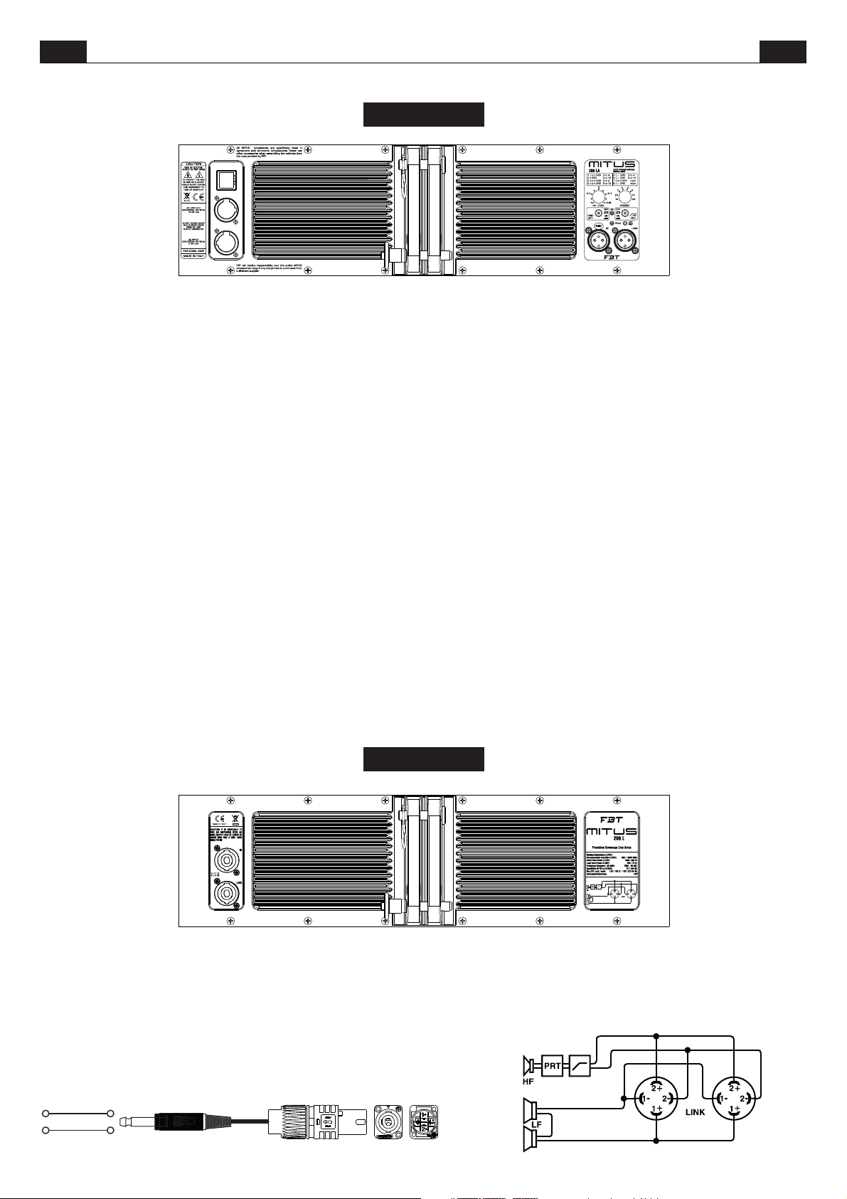
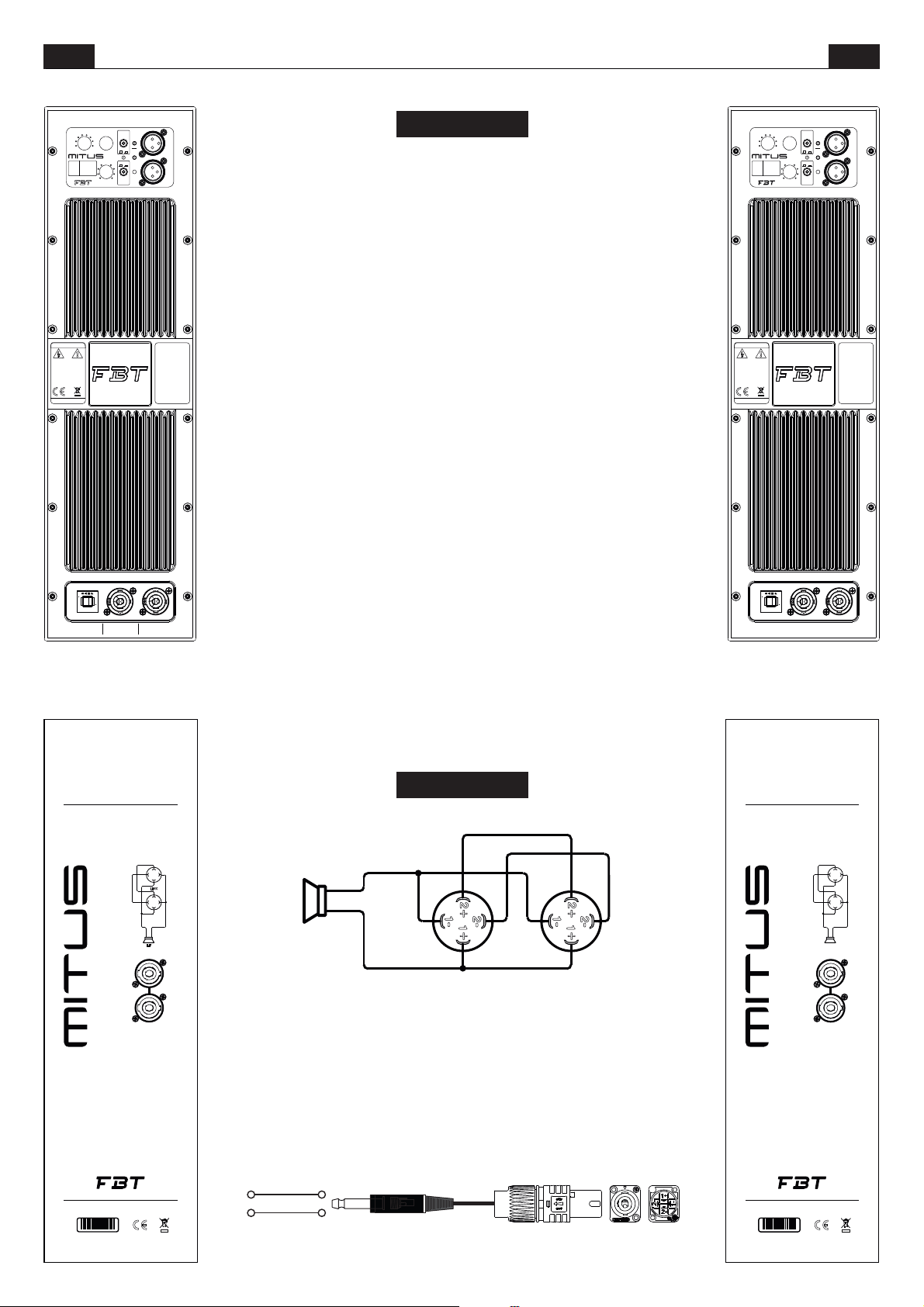
Le prese Speakon sono collegate in parallelo; utilizzare una presa per il
collegamento del box all’uscita di un amplificatore di potenza, l’altra per
collegare un secondobox.
È necessario scegliere cavi per diffusori con un diametro sufficiente in
funzione della lunghezza totale del collegamento. La resistenza introdotta
da un cablaggio inadeguato verso i diffusori riduce sia la potenza in uscita
sia il fattoredismorzamento dell’altoparlante.
*SPEAKON è un marchio registrato NEUTRIK
*SPEAKON is a registered trademark of NEUTRIK
TIP
PIN 1+
PIN 1-SLEEVE
206L
16/16 Ohm
Speakon connectors are connected in parallel mode. One connector can be
used to connect the box to the output of a power amplifier, the other to
connect to asecond box.
Loudspeaker cables shall have the adequate diameter, depending on the
overall lenght ofthe connection. The resistanceintroduced by aninadequate
wiring towards the loudspeakers would reduce both the power output and
the damping factorof the loudspeaker.
6
Page 10
ITA UK
CONTROLLI E FUNZIONI
CONTROLS AND FUNCTIONS
212FSA
CAUTION
POWER
CONSUMPTION: 640W
16.8A max
AC LOOP OUT
220-230Vac50/60Hz
2.8A max
AC INPUT
220-230Vac50/60Hz
DO NOT EXCEED RATED MAX CURRENT DRAW FROM AC LOOP OUTPUT CONNECTOR
RISK OF ELECTRIC SHOCK DO NOT OPEN
TO PREVENT THE RISK OF FIRE OR ELECTRIC
SHOCK NEVER EXPOSE THIS EQUIPMENT
TO RAIN OR MOISTURE
MADE IN ITALY
All MITUS accessories are specifically
rated in agreement with structural
comp utat ions . N ever use o ther
accessor ies wh en ass embling the
cabinets than the ones provided by FBT:
FBT will decline responsibility over the
entire MITUS accessories range if any
componentis purchased from adifferent
supplier.
ACTIVE SUBWOOFER
1- HUNG
2- HUNG PUNCH
3- HUNG with INFRA
4- GROUND
5- GROUND PUNCH
6- GROUND with INFRA
7- GND CARDIOID FRONT
8- GND CARDIOID REAR
0
0
GND
LIFT
0
+6dB
OFF
ON
IN LINK
212 FSA
1.5
2
2.5
1
3
0.5
3.5
0
mt.
DELAY
4
5
3
6
7
2
1
8
PRESETLEVEL
0!
ON
180!
PHASE
LMT
PEAK
PRT
DELAY:
Controllo di una linea di ritardo digitale che agisce sul segnale di
ingresso; in questo modo è possibile compensare il disallineamento sul
piano verticaledi sube satellite.Il delayè espressoin metrie vada 0.5a 3.5
metri a passidi50 cm.
LEVEL:
Regola il illivello generale del segnale.
PRESET: Seleziona 8 preset ad ognuno dei quali corrisponde una
configurazione di diffusori, in base alle preferenze personali e all'acustica
dell'ambiente di ascolto( vedi sezione PRESET).
GND LIFT:
Interruttore perla separazioneelettrica tra il circuito di massa e il
circuito di terra onde evitare possibili “loop” di massa, causa di fastidiosi
ronzii.
ON:
Indica l'attivazione delsistema.
PHASE:
Il controllo Phase consente di ottimizzare l'allineamento di fase,
cioè di ottenere una risposta in frequenza uniforme nellazona di incrocio tra
sub e satellite. Nella posizione 0° l'emissione sonora del sub è in fase con il
segnale di ingresso;nella posizione 180°l'emissione sonora èincontro-fase
con il segnale di ingresso; questo controllo consente di ottenere ulteriore
flessibilità nella messaa punto del subwooferottimizzandone le prestazioni.
PEAK:
L'accensione di questoled indica cheil livello delsegnale è prossimo
alla saturazione.
LMT/PRT:
L'accensione del led indica il malfunzionamento del sistema
dovuto ad un guasto dell'amplificatore interno o all'intervento dei circuiti di
limitazione per evitaresovraccarico termico.
IN-LINK:
Prese di ingresso/uscita bilanciate; “IN” consente il collegamento
di un segnale preamplificato come ad esempio quello in uscita da un mixer;
“LINK” permette ilcollegamentodi più diffusoriconlo stesso segnale.
DELAY:
Control of a digital delay line acting on the input signal; in this way it
is possible to make up for the vertical misalignment of sub and satellite. The
Delay is expressedin metres and goesfrom 0.5 to 3.5m with 50cmsteps.
LEVEL:
It adjusts thesignal general level.
PRESET: Selects 8 presets, each of whom corresponds to a specific
speaker configuration according to users' personal preferences and to the
acoustics of thelistening area (see PRESETsection.)
GND LIFT:
A switch forthe electric separationbetween the groundand earth
circuits; this can be useful in order to remove the irritating noises caused by
ground loops.
ON:
Indicates that the system is on.
PHASE:
The Phase controlallows to optimize phasealignment, i.e. toobtain
a uniform frequencyresponse in the crossoverarea between thesuband the
satellite. When it is set at 0°, the sound emission is in phase with the input
signal; when it is set at 180° the sound emission is in counterphase with the
input signal; thanks to this control, subwoofer adjustment will be even more
flexible with aconsequent performance optimization.
PEAK:
When this LED lights up, it indicates that the signal is reaching
saturation.
LMT/PRT:
If this LED lights up, there is a system malfunction due to an
internal amplifier failure or to the intervention of current limiting circuits
against thermal overload.
IN-LINK:
Balanced input/output sockets; “IN” allows to connect a preamplified signalsuch as that coming, for instance, from mixer output. “LINK”
allows to connectmultiple speakers to thesame signal.
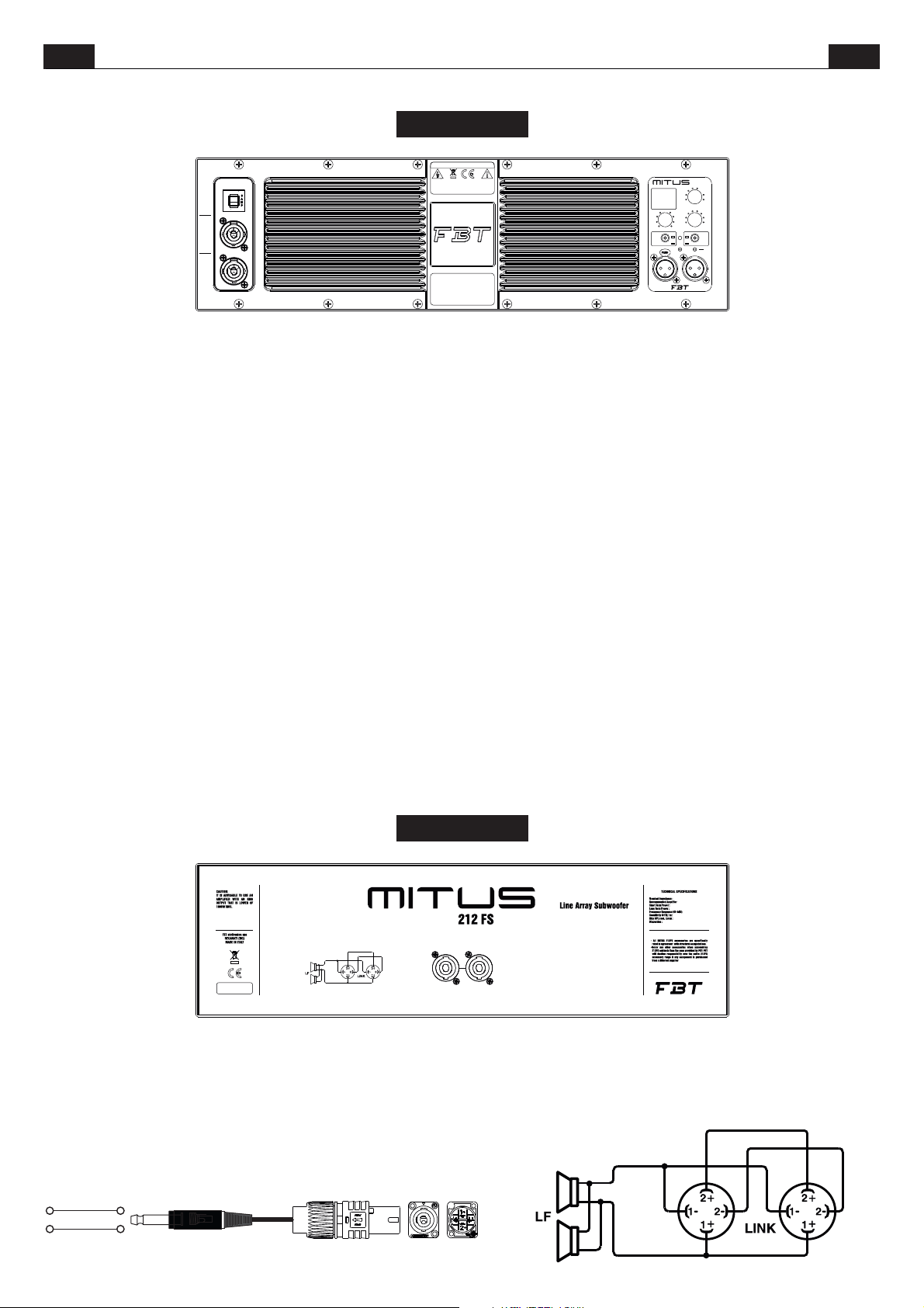
Le prese Speakon sono collegate in parallelo; utilizzare una presa per il
collegamento del box all’uscita di un amplificatore di potenza, l’altra per
collegare un secondobox.
È necessario scegliere cavi per diffusori con un diametro sufficiente in
funzione della lunghezza totale del collegamento. La resistenza introdotta
da un cablaggio inadeguato verso i diffusori riduce sia la potenza in uscita
sia il fattoredismorzamento dell’altoparlante.
*SPEAKON è un marchio registrato NEUTRIK
*SPEAKON is a registered trademark of NEUTRIK
TIP
PIN 1+
PIN 1-SLEEVE
212FS
8 Ohm
1000 W RMS
2000 W
500 W
50 Hz - 120 HZ
99 dB
134 / 138 dB
omnidirectional
LINKIN
Speakon connectors are connected in parallel mode. One connector can be
used to connect the box to the output of a power amplifier, the other to
connect to asecond box.
Loudspeaker cables shall have the adequate diameter, depending on the
overall lenght ofthe connection. The resistanceintroduced by aninadequate
wiring towards the loudspeakers would reduce both the power output and
the damping factorof the loudspeaker.
7
Page 11
ITA UK
CONTROLLI E FUNZIONI
CONTROLS AND FUNCTIONS
210MA
CAUTION
RISK OF ELECTRIC SHOCK DO NOT OPEN
POWER
CONSUMPTION: 640W
16.8A max
AC LOOP OUT
220-230Vac50/60Hz
2.8A max
AC INPUT
220-230Vac50/60Hz
DO NOT EXCEED RATED MAX CURRENT DRAW FROM AC LOOP OUTPUT CONNECTOR
TO PREVENT THE RISK OF FIRE OR ELECTRIC
SHOCK NEVER EXPOSE THIS EQUIPMENT
TO RAIN OR MOISTURE
MADE IN ITALY
AllMITUS accessories are specifically
rated in agreement with structural
computati ons. Ne ver use other
accessories when assembling the
cabinets than the ones provided by
FBT: FBT will decline responsibility
over the entire MITUS accessories
range if any component is purchased
froma differentsupplier.
210 MA
1) ORIGINAL
2) VOCAL
3) WARM
4) HI-ENDSYSTEM
0
0
GND
LIFT
0
+6dB
LEVEL
OFFONOFF
ACTIVE STAGE MONITOR
5) FOH
6) FOHVOCAL
7) FOHWARM
8) DRUMFILL
4
3
2
1
PRESET
ON
ON
PEAK
IN LINK
5
6
7
8
HP
FILT.
LMT
PRT
PRESET:
Seleziona 8 preset ad ognuno dei quali corrisponde diversa
equalizzazione, in base alle preferenze personali e all'acustica
dell'ambiente di ascolto( vedi sezione PRESET).
Regola il livellogenerale del segnale.
LEVEL:
GND LIFT:
Interruttore perla separazioneelettrica tra il circuito di massa e il
circuito di terra onde evitare possibili “loop” di massa, causa di fastidiosi
ronzii.
Indica l'attivazione delsistema.
ON:
HP FILTER:
Interruttore per l'attivazione del dispositivo di filtro low-cut che
lascia passare inuscitasolo le frequenzepiù alte della “frequenzadi taglio”.
L'accensione di questoled indica cheil livello delsegnale è prossimo
PEAK:
alla saturazione.
LMT/PRT:
L'accensione del led indica il malfunzionamento del sistema
dovuto ad un guasto dell'amplificatore interno o all'intervento dei circuiti di
limitazione per evitaresovraccarico termico.
IN-LINK:
Prese di ingresso/uscita bilanciate; “IN” consente il collegamento
di un segnale preamplificato come ad esempio quello in uscita da un mixer;
“LINK” permette ilcollegamentodi più diffusoriconlo stesso segnale.
PRESET:
Selects 8 presets, each of whom corresponds to a different
equalization according to users' personal preferences and to the acoustics
of the listeningarea (see PRESET section.)
Adjusts the signalgeneral level.
LEVEL:
GND LIFT:
A switch forthe electric separationbetween the groundand earth
circuits; this can be useful in order to remove the irritating noises caused by
ground loops.
Indicates that thesystem is on.
ON:
HP FILTER:
This switch activates the low-cut filter which lets only the
frequencies above thecut-off frequency pass atthe output.
When this LED lights up, it indicates that the signal is reaching
PEAK:
saturation.
LMT/PRT:
If this LED lights up, there is a system malfunction due to an
internal amplifier failure or to the intervention of current limiting circuits
against thermal overload.
IN-LINK:
Balanced input/output sockets; “IN” allows to connect a preamplified signal such as that coming, for instance, from mixer output. “LINK”
allows to connectmultiple speakers to thesame signal.
FBT elettronica spa - RECANATI (MC) MADE IN ITALY
HF
PRT
PRT
LF
LINK IN
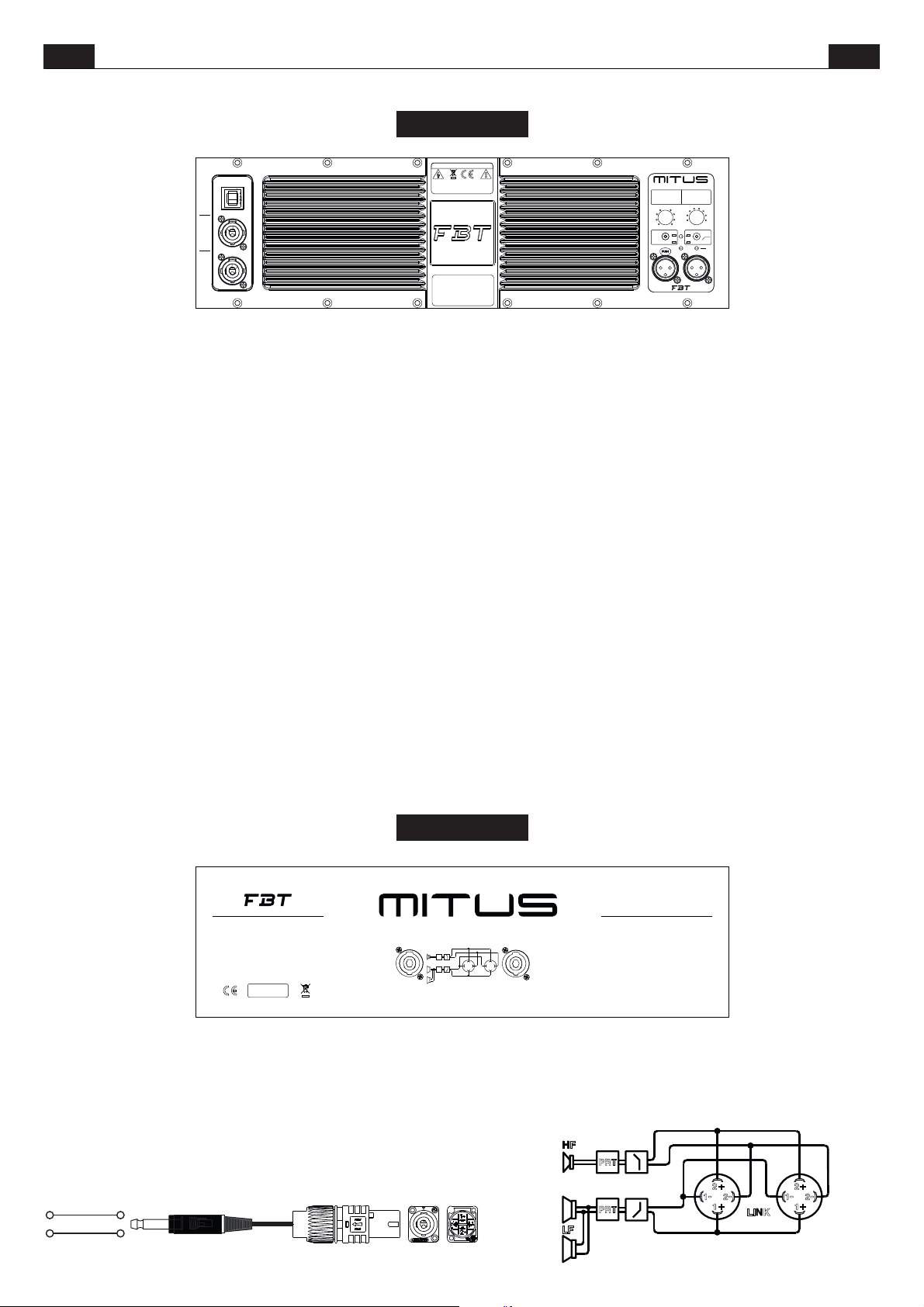
Le prese Speakon sono collegate in parallelo; utilizzare una presa per il
collegamento del box all’uscita di un amplificatore di potenza, l’altra per
collegare un secondobox.
È necessario scegliere cavi per diffusori con un diametro sufficiente in
funzione della lunghezza totale del collegamento. La resistenza introdotta
da un cablaggio inadeguato verso i diffusori riduce sia la potenza in uscita
sia il fattoredismorzamento dell’altoparlante.
*SPEAKON è un marchio registrato NEUTRIK
*SPEAKON is a registered trademark of NEUTRIK
TIP
PIN 1+
PIN 1-SLEEVE
210M
Sound Reinforcement Stage Monitor
210M
2+
2+
-
-
1
1
2-
2-
+
+
1
1
LINK
Speakon connectors are connected in parallel mode. One connector can be
used to connect the box to the output of a power amplifier, the other to
connect to asecond box.
Loudspeaker cables shall have the adequate diameter, depending on the
overall lenght ofthe connection. The resistanceintroduced by aninadequate
wiring towards the loudspeakers would reduce both the power output and
the damping factorof the loudspeaker.
HF
LF
8
TECHNICAL SPECIFICATIONS
NominalImpedance :
RecommendedAmplifier
ShortTermPower :
LongTermPower :
FrequencyResponse (@-6dB):
Sensitivity@1W,1m:
MaxSPL cont./ peak:
Dispersion:
CAUTION:
IT IS IMPORTANT TO USE AN AMPLIFIER THAT DOES NOT EXCEED
800W RMS @ 8 OHM
PRT
PRT
800 W RMS
1600 W
65Hz - 20kHZ
128 / 132 dB
70 conical°
8 Ohm
400 W
100 dB
)
2+
)
)
1-
2-
+
)
1
LINK
)
2+
)
1-
+
)
1
)
2-
Page 12
ITA UK
CONTROLLI E FUNZIONI
CONTROLS AND FUNCTIONS
PRESET
1- ORIGINAL
4
5
ACTIVE SPEAKER
3
2
1
0
0
0
LEVEL
220-230Vac 50/60Hz
6
7
8
+6dB
AC LOOP OUT
16.8A max
HP
FILT.
LMT
OFF ON
PRT
ON
PEAK
OFF ON
GND
LIFT
220-230Vac 50/60Hz
2- NEARFIELD
3- FARFIELD
4- FLOOR
5- VOCAL
6- LOUDNESS
7- WARM
8- HI-END SYSTEM
112 A
CAUTION
RISK OF ELECTRIC
SHOCK DO NOT OPEN
TO PREVENT THE RISK
OF FIRE OR ELECTRIC
SHOCK NEVER EXPOSE
THIS EQUIPMENT
TO RAIN OR MOISTURE
MADE IN ITALY
DO NOT EXCEED RATED MAX CURRENT DRAW FROM AC LOOP OUTPUT CONNECTOR
POWER
CONSUMPTION: 640W
A l l M I T U S
acc ess ori es are
specifically rated in
agr ee men t with
s t r u c t u r a l
computations.
Never use othe r
accesso ries when
as sem bl in g the
cabinets than the
ones p rovided by
FBT: FBT will decline
responsibi lity ov er
the entire MITUS
accessories range if
any component is
purchased from a
differentsupplier.
AC INPUT
2.8A max
LINK
PRESET:
q u a l i c o r r i sp on d e u n a d i v e r sa
IN
equalizzazione, in base alle preferenze
Seleziona 8 preset ad ognuno dei
personali e all'acustica dell'ambiente di
ascolto ( vedisezionePRESET ).
LEVEL:
Regola il livello generale del
segnale.
GND LIFT:
Interruttore per la separazione
elettrica tra il circuito di massa e il circuito di
terra onde evitare possibili “loop” di massa,
causa di fastidiosironzii.
Indica l'attivazione delsistema.
ON:
HP FILTER:
Interruttore per l'attivazione del
dispositivo di filtro low-cut che lascia passare
in uscita solo le frequenze più alte della
“frequenza di taglio”.
L'accensione diquesto led indica che
PEAK:
il livello del segnale è prossimo alla
saturazione.
LMT/PRT:
L'accensione del led indica il
malfunzionamento del sistema dovuto ad un
gua sto del l'am plif icat o re int e rno o
all'intervento dei circuiti di limitazione per
evitare sovraccarico termico.
IN-LINK:
Prese di ingresso/uscita bilanciate;
“IN” consente il collegamento di un segnale
preamplificato come ad esempio quello in
uscita da un mixer; “LINK” permette il
collegamento di più diffusori con lo stesso
segnale.
112A / 115A
PRESET:
corresponds to a different equalization
according to users' personal preferences and
to the acoustics of the listening area (see
PRESET section.)
LEVEL:
GND LIFT:
separation between the ground and earth
circuits; this can be useful in order to remove
the irritating noisescaused by ground loops.
Indicates that thesystem is on.
ON:
HP FILTER:
filter which lets only the frequencies above
the cut-off frequencypass at the output.
PEAK:
that the signalis reaching saturation.
LMT/PRT:
system malfunction due to an internal
amplifier failure or to the intervention of
current limiting circuits against thermal
overload.
IN-LINK:
allows to connect a pre-amplified signal such
as that coming, for instance, from mixer
output. “LINK” allows to connect multiple
speakers to thesame signal.
Selects 8 presets, each of whom
Adjusts the signalgeneral level.
A switch for the electric
This switchactivates thelow-cut
When this LED lights up, it indicates
If this LED lights up, there is a
Balanced input/output sockets; “IN”
PRESET
1- ORIGINAL
4
5
ACTIVE SPEAKER
3
2
1
0
0
LEVEL
220-230Vac 50/60Hz
0
6
7
8
+6dB
AC LOOP OUT
16.8A max
HP
FILT.
LMT
OFF ON
PRT
ON
PEAK
OFF ON
GND
LIFT
220-230Vac 50/60Hz
2- NEARFIELD
3- FARFIELD
4- FLOOR
5- VOCAL
6- LOUDNESS
7- WARM
8- HI-END SYSTEM
115 A
CAUTION
RISK OF ELECTRIC
SHOCK DO NOT OPEN
TO PREVENT THE RISK
OF FIRE OR ELECTRIC
SHOCK NEVER EXPOSE
THIS EQUIPMENT
TO RAIN OR MOISTURE
MADE IN ITALY
DO NOT EXCEED RATED MAX CURRENT DRAW FROM AC LOOP OUTPUT CONNECTOR
POWER
CONSUMPTION: 640W
A l l M I T U S
acc ess ori es are
specifically rated in
agr ee men t with
s t r u c t u r a l
computations.
Never use othe r
accesso ries when
as sem bl in g the
cabinets than the
ones p rovided by
FBT: FBT will decline
responsibi lity ov er
the entire MITUS
accessories range if
any component is
purchased from a
differentsupplier.
AC INPUT
2.8A max
LINK
IN
TECHNICAL SPECIFICATIONS
NominalImpedance :
RecommendedAmplifier
ShortTerm Power:
LongTerm Power:
FrequencyResponse (@-6dB):
Sensitivity@1W,1m :
MaxSPL cont./ peak :
700 W RMS
1200 W
55 Hz - 18 kHZ
127 / 131 dB
8 Ohm
350 W
99 dB
Sound Reinforcement Speaker
112
2-
+
2+
1
-
1
LINK
2-
+
2+
1
-
1
PRT
LFHF
CAUTION:
IT IS ADVISABLE TO USE AN AMPLIFIER WITH AN RMS
OUTPUTTHAT ISLOWER OF700W RMS.
112 / 115
PIN 1+
PRT
PRT
2+
)
LINK
2-
1-
)
1
)
+
)
2+
)
2-
1-
)
1
)
+
)
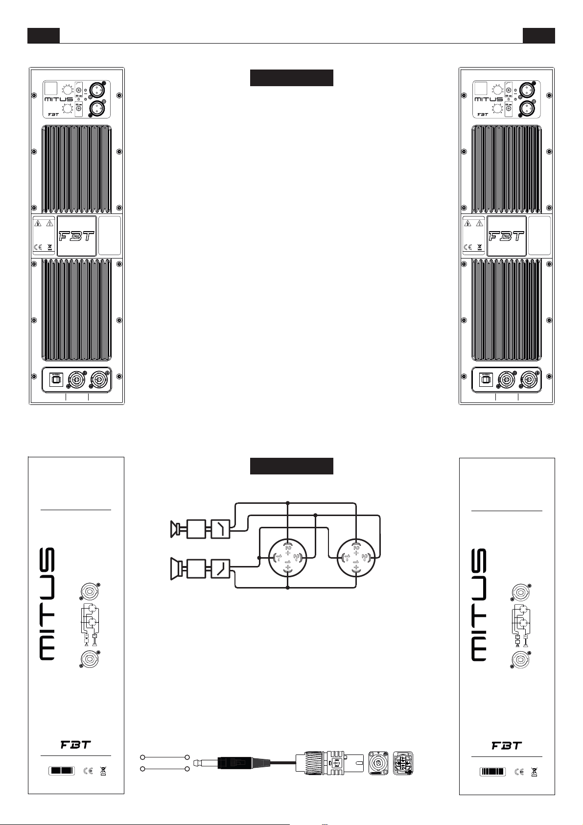
Speakon connectors are connected in
parallel mode. One connector can be used to
connect the box to the output of a power
amplifier, the other to connect to a second
box.
Loudspeaker cables shall have the adequate
diameter, depending on the overall lenght of
the connection.The resistance introduced by
an ina dequ a te wir i ng tow a rds t h e
loudspeakers would reduce both the power
output and the damping factor of the
loudspeaker.
HF
LF
IN
Le prese Speakon sono collegate in
parallelo; utilizzare una presa per il
collegamento del box all’uscita di un
amplificatore di potenza, l’altra per collegare
un secondo box.
LINK
È necessario scegliere cavi per diffusori con
un diametro sufficiente in funzione della
lunghezza totale del collegamento. La
resistenza introdotta da un cablaggio
inadeguato verso i diffusori riduce sia la
po ten za i n usc ita sia i l fattore di
smorzamento dell’altoparlante.
TIP
TECHNICAL SPECIFICATIONS
NominalImpedance :
RecommendedAmplifier
ShortTerm Power:
LongTerm Power:
Frequency Response (@6dB):
Sensitivity@1W,1m :
8 Ohm
800 W RMS
1400 W
400 W
50 Hz - 18 kHZ
100 dB
128 / 132 dB
Sound Reinforcement Speaker
115
2-
+
2+
1
1
-
LINK
2-
+
2+
1
-
1
PRT
LFHF
CAUTION:
IT IS ADVISABLE TO USE AN AMPLIFIER WITH AN RMS
OUTPUTTHAT ISLOWER OF800W RMS.
IN
LINK
12 3 4 56 7 8 9
FBT elettronica spa - RECANATI (MC) MADE IN ITALY
PIN 1-SLEEVE
*SPEAKON è un marchio registrato NEUTRIK
*SPEAKON is a registered trademark of NEUTRIK
12 3 4 56 7 8 9
FBT elettronica spa - RECANATI (MC) MADE IN ITALY
9
Page 13
ITA UK
TROMBA RUOTABILE
ROTATABLE HORN
112 / 112A
115 / 115A
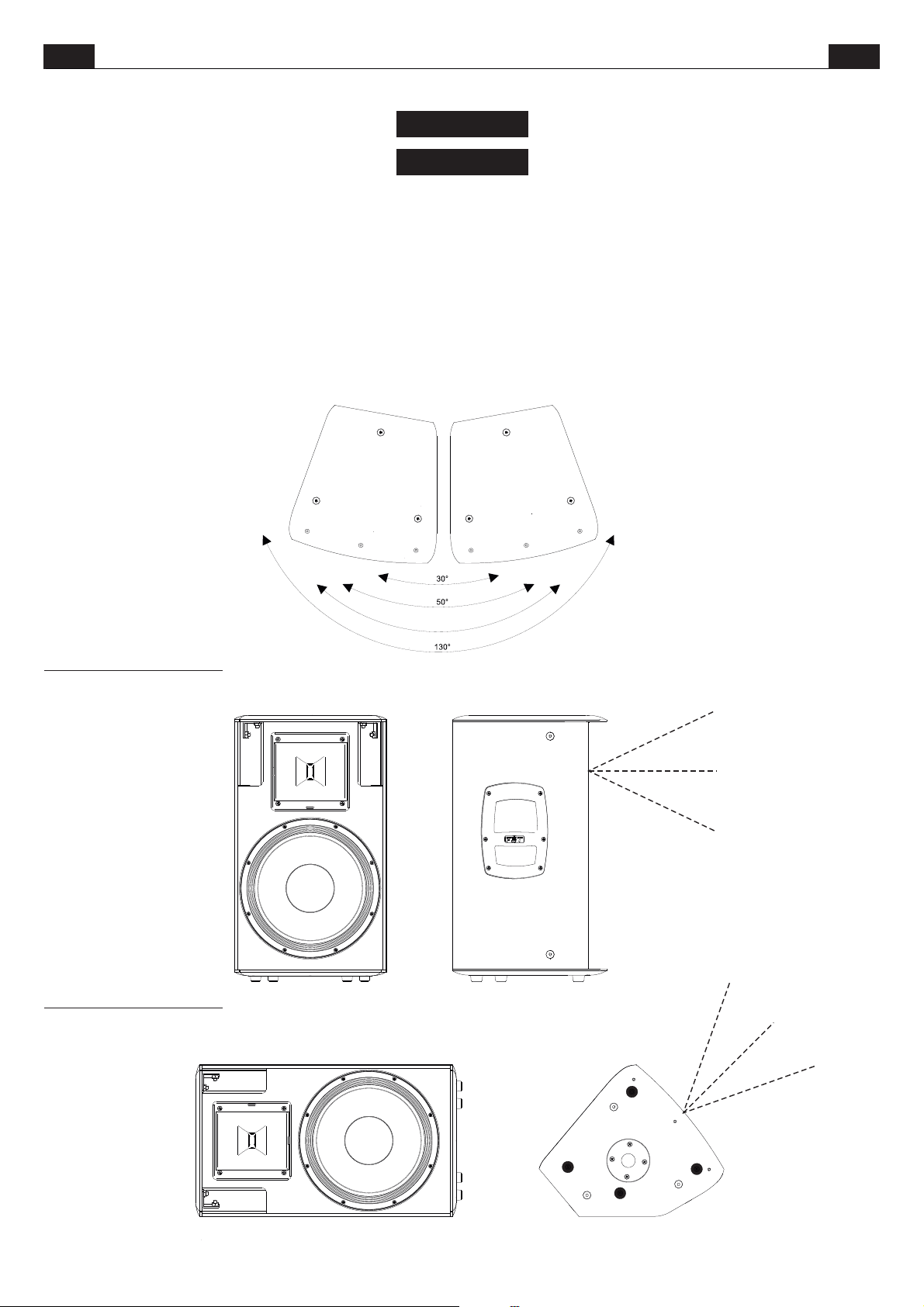
I modelli MITUS 112/112A e MITUS 115/115A sono equipaggiati con tromba
ruotabile a dispersioneasimmetrica.
Rimuovendo le viti di fissaggio della tromba è possibile ruotarla per variare
l’angolo di dispersione quando i diffusori vengono utilizzati in posizione
orizzontale o quandovengono affiancati formando unarray.
30° ----- angolo tra diffusori con trombaposizionata a 50°
50° ----- angolo tra diffusori con trombaposizionata a 80°
80° ----- copertura totale con tromba posizionata a50°
130°----- copertura totale con trombaposizionata a 80°
80°
MITUS 112 and MITUS 115 models have an asymmetrical dispersion
rotatable horn.
By removing the fixing screws of the horn it is possible to rotate it so as to
change the dispersion angle when the speakers are used in horizontal
position or whenthey are aligned inan array.
30° ----- with 50° horn position
50° ----- with 80° horn position
80° ----- total coverage with 50° horn position
130°----- total coverage with 80° horn position
FRONT OF HOUSE
STAGE MONITOR
80°
50°
80°
50°
10
Page 14
ITA UK
CONTROLLI E FUNZIONI
CONTROLS AND FUNCTIONS
PRESET
DELAY
PHASE
1.5
2
5
4
2.5
1
3
6
0.5
3
2
7
1
8
3.5
mt.
ACTIVE SUBWOOFER
Original:
Infra:
0
0
LEVEL
220-230Vac 50/60Hz
TECHNICAL SPECIFICATIONS
121 SA
0
+6dB
AC LOOP OUT
16.8A max
OFF ON
GND
LIFT
180!0!
ON
LMT
PRT
PEAK
220-230Vac 50/60Hz
29 Hz - 250 HZ
omnidirectional
2000 W RMS
136 / 139 dB
0
1- ORIGINAL
5- CARDIOID FRONT
2- DEEP
3- PUNCH
6- CARDIOID REAR
4- INFRA
7-CARDIOID FRONT
8-CARDIOID REAR
CAUTION
RISK OF ELECTRIC
SHOCK DO NOT OPEN
TO PREVENT THE RISK
OF FIRE OR ELECTRIC
SHOCK NEVER EXPOSE
THIS EQUIPMENT
TO RAIN OR MOISTURE
MADE IN ITALY
DO NOT EXCEED RATED MAX CURRENT DRAW FROM AC LOOP OUTPUT CONNECTOR
POWER
CONSUMPTION: 640W
NominalImpedance :
RecommendedAmplifier
ShortTerm Power:
LongTerm Power:
FrequencyResponse (@-6dB):
Sensitivity@1W,1m :
MaxSPL cont./ peak :
Dispersion:
Sound Reinforcement Subwoofer
A l l M I T U S
acc ess ori es are
specifically rated in
agr ee men t with
s t r u c t u r a l
computations.
Never use othe r
accesso ries when
as sem bl in g the
cabinets than the
ones p rovided by
FBT: FBT will decline
responsibi lity ov er
the entire MITUS
accessories range if
any component is
purchased from a
differentsupplier.
AC INPUT
2.8A max
4 Ohm
3600 W
1000 W
99 dB
LINK
DELAY:
digitale cheagisce sulsegnale diingresso; in
IN
questo modo è possibile compensare il
Controllo di una linea di ritardo
disallineamento sul piano verticale di sub e
satellite. Il delay è espresso in metri e va da
0.5 a 3.5metria passi di50 cm.
LEVEL:
Regola il il livello generale del
segnale.
PRESET: Seleziona 8 preset ad ognuno dei
quali corrisponde una configurazione di
diffusori, in base alle preferenze personali e
all'acustica dell'ambiente di ascolto ( vedi
sezione PRESET ).
GND LIFT:
Interruttore per la separazione
elettrica tra il circuito di massa e il circuito di
terra onde evitare possibili “loop” di massa,
causa di fastidiosironzii.
ON:
Indica l'attivazione delsistema.
PHASE:
Il controllo Phase consente di
ottimizzare l'allineamento di fase, cioè di
ottenere una risposta in frequenza uniforme
nella zona di incrocio tra sub e satellite. Nella
posizione 0° l'emissione sonora del sub è in
fase con il segnale di ingresso; nella
posizione 180° l'emissione sonora è in
contro-fase con il segnale diingresso; questo
controllo consente di ottenere ulteriore
flessibilità nella messa a puntodel subwoofer
ottimizzandone le prestazioni.
PEAK:
L'accensione diquesto led indica che
il livello del segnale è prossimo alla
saturazione.
LMT/PRT:
L'accensione del led indica il
malfunzionamento del sistema dovuto ad un
gua sto del l'am plif icat o re int e rno o
all'intervento dei circuiti di limitazione per
evitare sovraccarico termico.
IN-LINK:
Prese di ingresso/uscita bilanciate;
“IN” consente il collegamento di un segnale
preamplificato come ad esempio quello in
uscita da un mixer; “LINK” permette il
collegamento di più diffusori con lo stesso
segnale.
121SA / 118SA
DELAY:
on the input signal; in this way it is possible to
make up for the vertical misalignment of sub
and satellite. The Delay is expressed in
metres and goes from 0.5 to 3.5m with 50cm
steps.
LEVEL:
PRESET: Selects 8 presets, each of whom
corresponds t o a s pec ifi c speaker
configuration according to users' personal
preferences and to the acoustics of the
listening area (seePRESET section.)
GND LIFT:
separation between the ground and earth
circuits; this can be useful in order to remove
the irritating noisescaused by ground loops.
Indicates that the system is on.
ON:
PHASE:
optimize phase alignment, i.e. to obtain a
uniform frequency response in the
crossover area between the sub and the
satellite. When it is set at 0°, the sound
emission is in phase with the input signal;
when it is set at 180° the sound emission is
in counterphase with the input signal;
thanks to this control, subwoofer
adjustment will be even more flexible with a
consequent performance optimization.
PEAK:
that the signalis reaching saturation.
LMT/PRT:
system malfunction due to an internal
amplifier failure or to the intervention of
current limiting circuits against thermal
overload.
IN-LINK:
allows to connect a pre-amplified signal such
as that coming, for instance, from mixer
output. “LINK” allows to connect multiple
speakers to thesame signal.
121S / 118S
Control of a digital delay line acting
It adjusts thesignal general level.
A switch for the electric
The Phase control allows to
When this LED lights up, it indicates
If this LED lights up, there is a
Balanced input/output sockets; “IN”
PRESET
DELAY
PHASE
1.5
2
5
4
2.5
1
3
6
0.5
3
2
7
1
8
3.5
mt.
118SA
ACTIVE SUBWOOFER
Original:
0
Infra:
0
0
LEVEL
220-230Vac 50/60Hz
TECHNICAL SPECIFICATIONS
OFF ON
+6dB
AC LOOP OUT
16.8A max
GND
LIFT
180!0!
ON
LMT
PRT
PEAK
220-230Vac 50/60Hz
1200 W RMS
36 Hz - 400 HZ
omnidirectional
135 / 138 dB
0
1- ORIGINAL
5- CARDIOID FRONT
2- DEEP
3- PUNCH
6- CARDIOID REAR
4- INFRA
7-CARDIOID FRONT
8-CARDIOID REAR
CAUTION
RISK OF ELECTRIC
SHOCK DO NOT OPEN
TO PREVENT THE RISK
OF FIRE OR ELECTRIC
SHOCK NEVER EXPOSE
THIS EQUIPMENT
TO RAIN OR MOISTURE
MADE IN ITALY
DO NOT EXCEED RATED MAX CURRENT DRAW FROM AC LOOP OUTPUT CONNECTOR
POWER
CONSUMPTION: 640W
NominalImpedance :
RecommendedAmplifier
ShortTerm Power:
LongTerm Power:
FrequencyResponse (@6dB):
Sensitivity@1W,1m :
MaxSPL cont./ peak :
Dispersion:
Sound Reinforcement Subwoofer
A l l M I T U S
acc ess ori es are
specifically rated in
agr ee men t with
s t r u c t u r a l
computations.
Never use othe r
accesso ries when
as sem bl in g the
cabinets than the
ones p rovided by
FBT: FBT will decline
responsibi lity ov er
the entire MITUS
accessories range if
any component is
purchased from a
differentsupplier.
AC INPUT
2.8A max
4 Ohm
2400 W
600 W
101 dB
LINK
IN
2
-
2+
+
1
-
1
2
-
2+
+
1
-
1
121 S
CAUTION:
ITIS IMPORTANT TO USE AN AMPLIFIERTHAT DOES NOT
EXCEED2000W RMS@ 4 OHM.
ATTENTION:
NOPASSIVE CROSSOVER INSIDE; ANEXTERNAL DIGITAL
PR OC ES SO R IS REQ UI RE D FOR OP TI M UM
PERFORMANCEAND WOOFERSAFETY.
PLEASEREFER TOOWNER!S MANUAL FORSETTINGS.
12 3 4 56 7 8 9
FBT elettronica spa - RECANATI (MC) MADE IN ITALY
LF
IN
Le prese Speakon sono collegate in
LINK
parallelo; utilizzare una presa per il
collegamento del box all’uscita di un
amplificatore di potenza, l’altra per collegare
un secondo box.
È necessario scegliere cavi per diffusori con
un diametro sufficiente in funzione della
lunghezza totale del collegamento. La
resistenza introdotta da un cablaggio
inadeguato verso i diffusori riduce sia la
po ten za i n usc ita sia i l fattore di
smorzamento dell’altoparlante.
TIP
*SPEAKON è un marchio registrato NEUTRIK
*SPEAKON is a registered trademark of NEUTRIK
PIN 1+
PIN 1-SLEEVE
2+
)
1
)
-
1
+
)
LINK
2
-
)
2+
)
1
2
)
-
-
1
)
+
)
Speakon connectors are connected in
parallel mode. One connector can be used to
connect the box to the output of a power
amplifier, the other to connect to a second
box.
Loudspeaker cables shall have the adequate
diameter, depending on the overall lenght of
the connection.The resistance introduced by
an ina dequ a te wir i ng tow a rds t h e
loudspeakers would reduce both the power
output and the damping factor of the
loudspeaker.
11
2
-
2+
+
1
-
1
LINK
2
-
2+
+
1
1
-
LF
118 S
CAUTION:
ITIS IMPORTANT TO USE AN AMPLIFIERTHAT DOES NOT
EXCEED1200W RMS@ 4 OHM.
ATTENTION:
NOPASSIVE CROSSOVER INSIDE; ANEXTERNAL DIGITAL
PR OC ES SO R IS REQ UI RE D FOR OP TI M UM
PERFORMANCEAND WOOFERSAFETY.
PLEASEREFER TOOWNER!S MANUAL FORSETTINGS.
12 3 4 56 7 8 9
FBT elettronica spa - RECANATI (MC) MADE IN ITALY
IN
LINK
Page 15
ITA
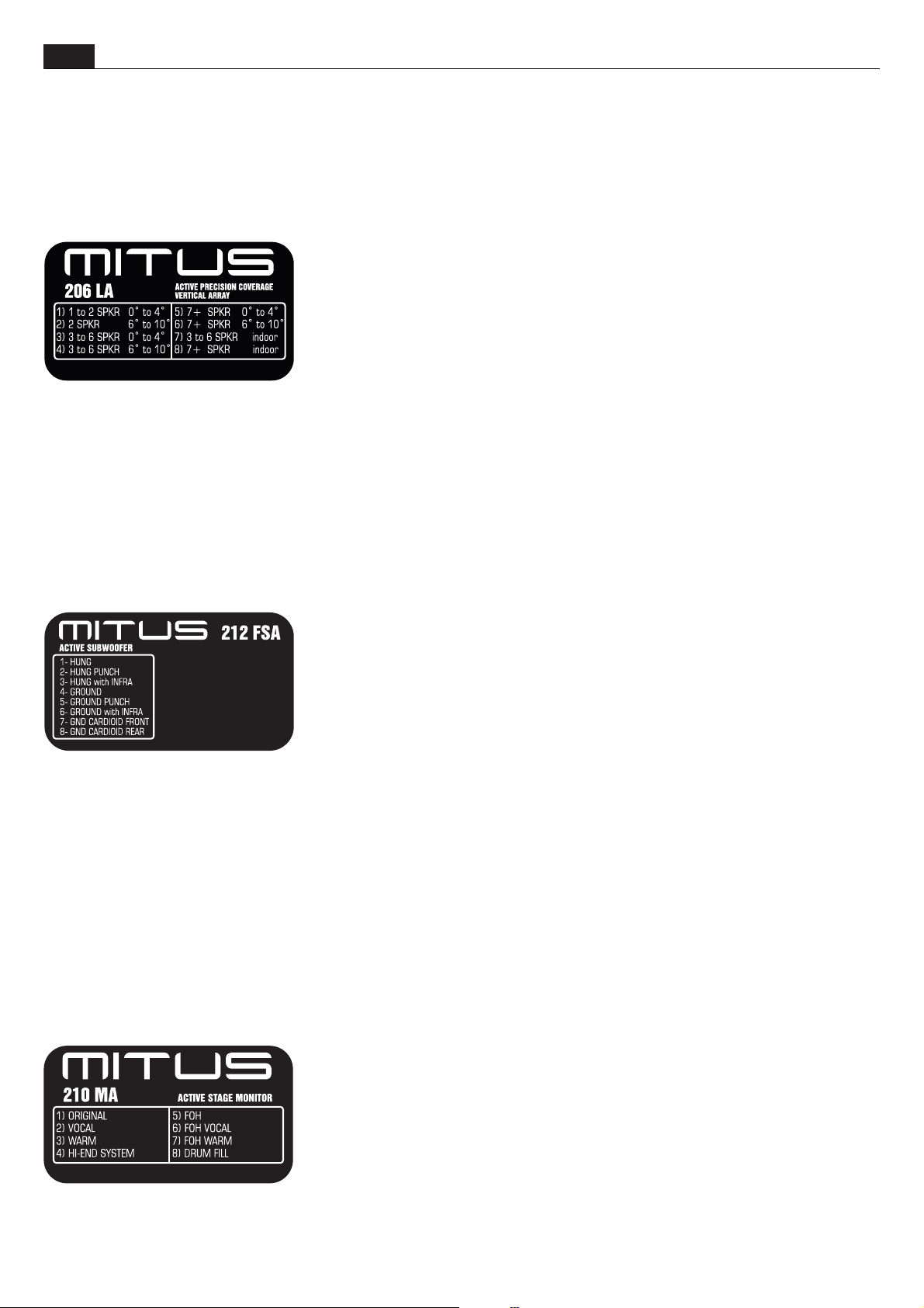
PRESET
Ogni diffusore della serie MITUS è dotato di 8 preset studiati per adattare la risposta del diffusore all’ambiente in cui verrà
utilizzato o specializzarlaa particolari utilizzi.
La selezione avvienetramite il commutatore "PRESET ."
I preset sono uno strumento rapidoe precisonelle mani dell’installatore o
nelle condizioni piùfrequenti di utilizzo.
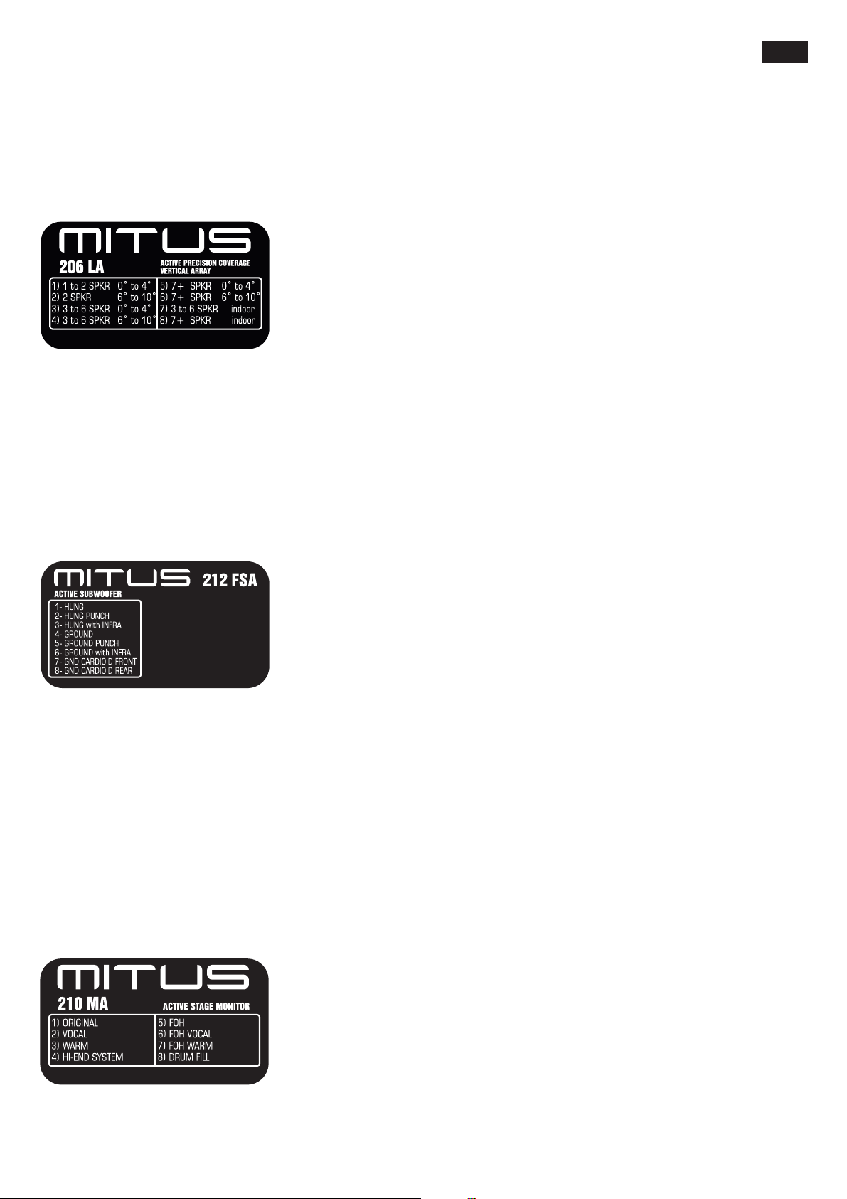
MITUS 206LA e l'angolo traessi è compreso tra0° e 4°
-3 to 6 SPKR- 6 to 10°:
compreso tra 6° e 10°. Per esempio se il sistema è composto da sei diffusori configurati a J con i seguenti angoli tra i diffusori
partendo dall'alto: 0°,2°, 4°, 6°, 8°,allora i primi 4diffusori sono configurati conil preset 3 to6 SPKR- 0 to4°, gli ultimi due(inclinati 6°
ed 8°), vannoconfigurati con il preset3 to 6SPKR- 6 to10°.
-7+ SPKR- 0 to4°:
-7+ SPKR- 6 to10°:
-3 to 6 SPKR- INDOOR:
dall'angolo tra essi,ed il sistema èutilizzato in localiriverberanti
-7+ SPKR- INDOOR:
ed il sistemaè utilizzato in localiriverberanti
Quando il sistema è composto da tre, quattro, cinque o sei diffusori MITUS 206LA e l'angolo tra essi è
Quando il sistemaè composto da 7o più diffusori MITUS 206LA e l'angolotra essi ècompreso tra 0° e4°
Quando il sistemaè composto da 7o più diffusori MITUS 206LA e l'angolotra essi ècompreso tra 6° e10°
Quando il sistema è composto da tre, quattro, cinque o sei diffusori MITUS 206LA indipendentemente
Quando il sistema è composto da da 7 o più diffusori MITUS 206LA indipendentemente dall'angolo tra essi,
differenti
del fonico pervelocizzare la fase diset-up dell’impianto
Il preset da scegliere dipende sostanzialmente dalla configurazione del sistema, cioè dal
numero di diffusori che compongono l'array e dall'inclinazione di ciascun diffusore. Gli
ultimi due preseti denominati INDOOR sono espressamente pensati per utilizzo in spazi
chiusi all'interno diedifici generalmente riverberanti.
-1 to 2 SPKR- 0 to 4°:
206LA e l'angolotra essi (nelcaso siano due) ècompreso tra 0°e 4°
-2 SPKR- 6 to 10°:
l'angolo tra essiè compreso tra 6°e 10°
3 to 6 SPKR- 0 to 4°:
- Quando il sistema è composto da tre, quattro, cinque o sei diffusori
Quando il sistema ècomposto da uno oppure due diffusori MITUS
Quando il sistema è composto da due diffusori MITUS 206LA e
Il preset da scegliere dipende dalla configurazione del sistema e dal tipo di suono
desiderato. Innanzi tutto bisogna scegliere il tipo di installazione tra GROUND (poggiato a
terra o sul palco) e HUNG (appeso sopra il MITUS 206LAo inuna colonnadi soli SUB), poi
a ciascuna di queste due tipologie di installazione sono associate diverse curve di
equalizzazione per cambiareil carattere del sounddel SUB.
-HUNG:
-HUNG PUNCH:
estensione in bassafrequenza ma più energiaconcentrata in gamma80-120Hz.
-HUNG with INFRA:
appeso sopra ilMITUS 206LAe MITUS 118SAoppure MITUS121SA appoggiati aterra. Questa tipologia disistema è lapiù completa
ed è indicata per grandi eventi e grandi spazi da sonorizzare soprattutto all'aperto, in quanto permette di avere una distribuzione di
energia a basse frequenze più uniforme in tutta l'area di ascolto. Il SUB MITUS 118SA/121SA poggiato a terra deve essere
configurato con ilpreset INFRA.
-GROUND:
-GROUND PUNCH:
concentrata in gamma80-120Hz.
-GROUND with INFRA:
appoggiati a terra. Questa tipologia di sistema è prevista se si vogliono utilizzare tutti i SUB disponibili per aumentare l'SPL ma non
c'è la possibilità di sospendere ilMITUS 212FSA. Il SUB MITUS 118SA/121SApoggiato a terra deve essereconfigurato con il preset
INFRA.
-CARDIOID FRONT:
-CARDIOID REAR:
rispetto al FRONT)
Sub a terra,curva di equalizzazione didefault, general pourpose.
Sub a terra, il suono del sub diventa più asciutto, meno estensione in bassa frequenza ma più energia
Il sistema è compostoda due diversi SUB, MITUS 212/FSA e MITUS118S/SAoppure MITUS121S/SA, tutti
Configurazione cardioide, settarequesto preset nel SUBrivolto verso l'audience
Configurazione cardioide, settare questo preset nel SUB rivolto verso il palco (ruotato fisicamente di 180°
Data la possibilità di utilizzare il diffusore come monitor da palco ma anche come diffusore
general purpose in applicazioni Front Of House, i presets sono suddivisi in 2 gruppi da 4
ciascuno. I primi4 presets sono per applicazionestage monitor,gli altri 4 (denominati FOH)
si usano con il diffusore installato su piantana o su americana e quando l'ascolto non è
ravvicinato.
installazione sospesa, curvadi equalizzazione di default,general purpose.
installazione sospesa, il suono del sub diventa più asciutto, meno
Il sistema è composto da due diversi SUB, MITUS 212FSA installato
La descrizione deisingoli presets rimane quella illustrata peri modelli MITUS 112Ae 115A,
eccetto per il DRUM FILL che è specializzato per il monitoraggio di batteristi
preferibilmente in abbinamento adun SUBWOOFER.
12
Page 16
ITA
PRESET
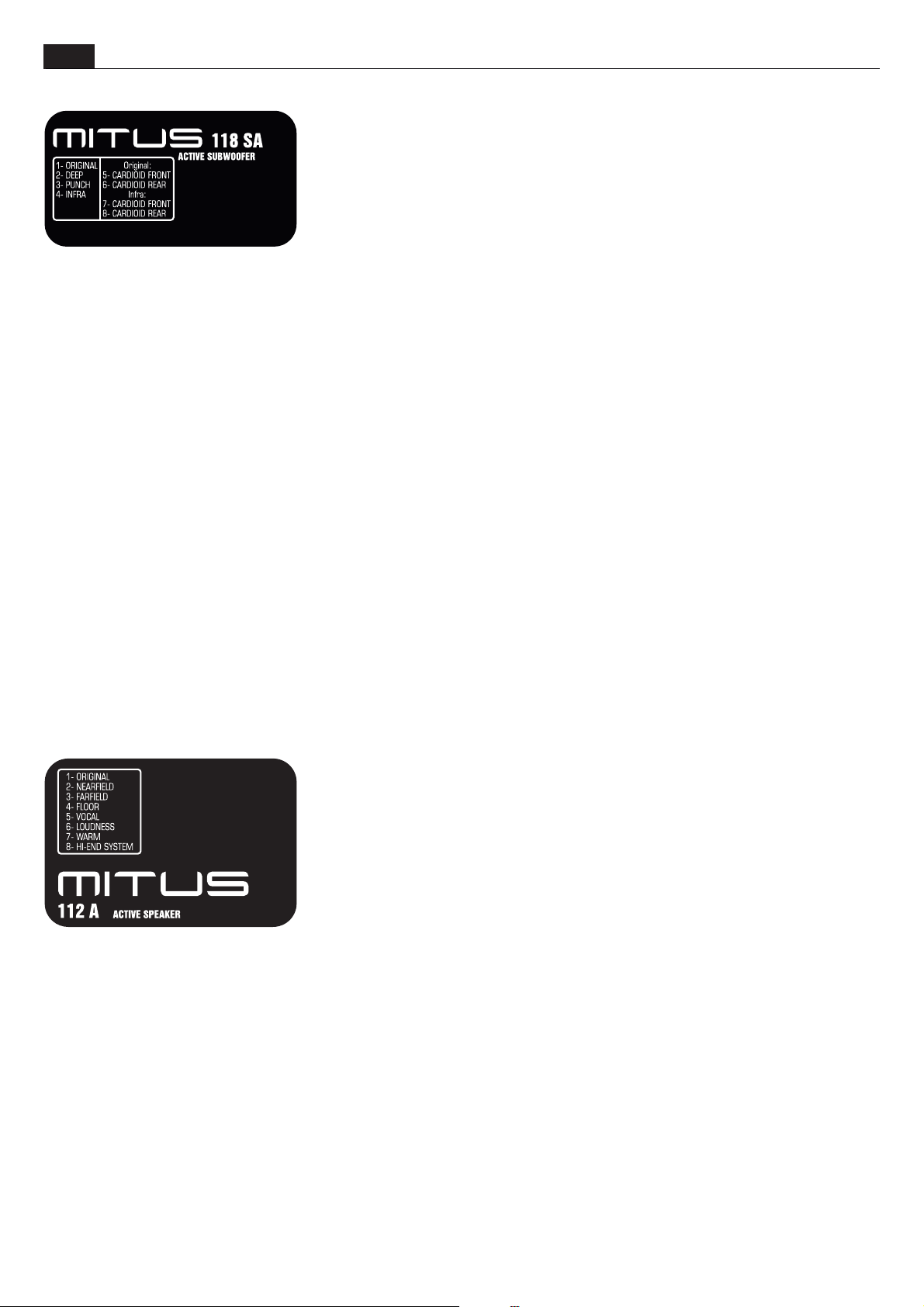
-ORIGINAL:
purpose, adatto quindialla maggior parte delleapplicazioni.
-DEEP:
molto profondo e morbido adatto in applicazioni di alta qualità e media energia quali
musica acustica, jazz,etc.
-PUNCH:
più energia concentratain gamma 80-120Hz. Adatto alrock e adapplicazioni ad alto SPL
-INFRA:
riprodotte soltanto le frequenze molto basse. Scegliere questo preset in sistemi dove sia
contemporaneamente presente il subwoofer MITUS 212FSA(settato con il preset'with infra')
ed il MITUS118/121SA
ORIGINAL - seguono due presets per configurazione cardioide con curva di equalizzazione ORIGINAL, cioè di default adatta ad
impieghi generici)
-CARDIOID FRONT:
-CARDIOID REAR:
rispetto al FRONT)
-Il sistema è composto da due diversi SUB, MITUS 212/FSA e MITUS 118SAoppure MITUS121SA, tutti appoggiati a terra. Questa
tipologia di sistema è prevista se si vogliono utilizzare tutti i SUB disponibili per aumentare l'SPL ma non c'è la possibilità di
sospendere il MITUS212FSA. Il SUB MITUS 118SA/121SA poggiato a terra deveessere configurato conil preset INFRA.
INFRA - seguono due presets per configurazione cardioide con curva di equalizzazione INFRA. Scegliere questi preset in sistemi
dove sia contemporaneamentepresente il subwoofer MITUS212FSA(settato con ilpreset 'with infra') edil MITUS 118/121SA
-CARDIOID FRONT:
-CARDIOID REAR:
rispetto al FRONT)
Configurazione cardioide, settarequesto preset nel SUBrivolto verso l'audience
Configurazione cardioide, settare questo preset nel SUB rivolto verso il palco (ruotato fisicamente di 180°
Configurazione cardioide, settarequesto preset nel SUBrivolto verso l'audience
Configurazione cardioide, settare questo preset nel SUB rivolto verso il palco (ruotato fisicamente di 180°
corrisponde al tipico sound FBT. E' il preset di default con utilizzo general
questo presetestende ed enfatizza la gamma bassa del subwoofer, per un suono
il suono del sub diventa più asciutto, meno estensione in bassa frequenza ma
Il filtro viene spostato a frequenza più bassa degli altri preset, quindi vengono
La presenza di 8 presets gestiti da DSP permette di modificare la risposta del diffusore in
maniera molto più accurata rispetto ai controlli di tono. Inoltre i preset sono già studiati ed
ottimizzati in cameraanecoica per dare aldiffusore esattamente il carattere voluto.
-ORIGINAL
purpose, adatto quindialla maggior parte delleapplicazioni.
-NEARFIELD:
o con l'audiencea distanza ravvicinata dovecomunque sia richiestoun SPLmedio-alto
-FARFIELD:
quando si hala necessità di proiettareil suono adistanze considerevoli.
-FLOOR:
compensata per tener conto della vicinanza con il pavimento e per l'ascolto in campo
vicino.
-VOCAL:
banda passante vienemodificata per esaltare lagamma vocale.
-LOUDNESS:
che rimangono leggermente arretrate. E' un preset molto piacevole da ascoltare a basso volume ma adatto anche per utilizzo del
diffusore in discoteche o pubs.
-WARM:
ambienti molto assorbentio nelle situazioni doveè richiesto unsuono molto energico allebasse frequenze edolce alle medio-alte
-HI-END SYSTEM:
grande linearità di risposta e banda passante non eccessivamente estesa agli estremi. Chi è abituato a lavorare con sistemi audio
altamente professionali troveràcon questo preset ilsound che cerca.
tipica curva di rispostaper applicazione musicale o disco, con bassi ed acuti enfatizzatirispetto alle medie frequenze
da un carattere corposo sul mediobasso e meno aggressivo sulla parte acuta. Adatto alla riproduzione di musica in
permette di avere la massima intelligibilità del parlato anche in ambienti difficili o con alto noise floor. La
è caratterizzato dalla tipica risposta dei diffusori di fascia top concepiti esclusivamente per il touring. Quindi
corrisponde al tipico sound FBT. E' il preset di default con utilizzo general
adatto ad un ascoltoravvicinato, fino a 7-8m. Consigliatoin piccoli ambienti
per un ascoltodel diffusore ad unadistanza maggiore di 15-20m.Indicato per
il diffusore si specializza per uso come stage monitor. La risposta viene
13
Page 17
PRESET
Every MITUS series speaker features 8 different presets designed to adapt the speaker answer to the environment where it will be used or
to make itsuitable for specialuses.
Selection is madethrough the “PRESET”switch.
The presets are a quick and precise tool for installers or sound technicians to speed up system setup according to the most frequent usage
conditions.
The preset to be chosensubstantially depends on the system configuration,i.e. from the number
of speakers in the array and the inclination of each one of them. The two last presets -called
INDOOR- are expressly designed for usage in enclosed areas inside generally reverberating
buildings.
-1 to 2 SPKR – 0 to4°: When thesystem is composed of one ortwo MITUS 206LA speakersand
the angle betweenthem (if theyare two) isbetween 0° and4°.
-2 SPKR – 6 to10°: When the system is composed oftwo MITUS 206LAspeakers and the angle
between them isbetween 6° and10°.
-3 to 6 SPKR – 0 to 4°: When the system is composed of three, four, five or six MITUS 206LA
speakers and theangle between themis between 0°and 4°.
-3 to 6 SPKR – 6 to 10°: When the system is composed of three, four, five or six MITUS 206LA speakers and the angle between them is
between 6° and 10°. For example if the system is composed of six speakers in a J shaped array with the following angles between the
speakers starting from the top: 0°, 2°, 4°, 6°,8°, then the first 4 speakers are configured with the '3 to 6 SPKR –0 to 4°' preset, while the last
two (with a6° and 8°inclination) have tobe configured withthe '3 to6 SPKR –6 to 10°'preset.
-7+ SPKR –0 to 4°: When thesystem is composed of 7or more MITUS206LAspeakers and theangle between themis between 0°and 4°.
-7+ SPKR – 6 to 10°: When the system is composed of 7 or more MITUS 206LA speakers and the angle between them is between 6° and
10°.
-3 to 6 SPKR – INDOOR: When the system is composed of three, four, five or six MITUS 206LA speakers regardless of the angle between
them, and thesystem is usedin reverberating rooms.
-7+ SPKR – INDOOR: When thesystem iscomposed of7 or more MITUS 206LA speakers regardless of the angle between them, and the
system is usedin reverberating rooms.
UK
The preset selection depends on system configuration and type of desired sound. First of all it is
necessary to choose the installation type between GROUND (laid on the ground or stage) and
HUNG (flown over the MITUS 206LA or in an array of SUBs only). Then different equalization
curves are to be associated to each one of these two installations in order to change the sound
characteristics of theSUB.
-HUNG: Flown installation,default equalization curve,general purpose.
-HUNG PUNCH: Flown installation, the sound of the sub becomes drier, reduced low frequency
extension but moreenergy concentrated inthe 80-120Hz range.
-HUNG with INFRA: The system is composed of two different SUBs, MITUS 212FSA flown over
MITUS 206LA and MITUS 118SA or MITUS 121SA laid on the ground. This type of system is the most complete and suitable to reproduce
sound in great events and over huge areas, most of all outdoor, since it permits obtaining a more even distribution of low frequency energy
over the wholelistening area. TheMITUS 118SA/121SASUB laid onthe ground hasto be configuredwith the INFRApreset.
-GROUND: Sub onthe ground, defaultequalization curve, generalpurpose.
-GROUND PUNCH: Sub on the ground, the sound of the sub becomes drier, reduced low frequency extension but more energy
concentrated in the80-120Hz range.
-GROUND with INFRA: The system is composed of two different SUBs, MITUS 212/FSA flown over MITUS 118/SA MITUS 121/SA, all laid
on the ground. This typeof system is recommended when youwant to use all the SUBsavailable in order to increasethe SPL but theMITUS
212FSAcannot be flown.The MITUS 118SA/121SASUB laid onthe ground hasto be configuredwith the INFRApreset.
-CARDIOID FRONT: Cardioid configuration, set thispreset on theSUB oriented towardthe audience
-CARDIOID REAR: Cardioid configuration, set this preset on the SUB oriented toward the stage (physically rotated 180° with respect to the
FRONT).
Since the speaker can be used both as stage monitor and general purpose speaker in Front Of
House applications, presets are divided into 2 groups of 4 presets each. The first 4 presets are
for stage monitor applications whereas the remaining 4 (called FOH) are to be used with the
speaker installed onpole or trussstand and whenthe audience isnot too close.
The description of the single presets is the same as that of models MITUS 112A and 115A,
except for the DRUMFILL which is specially designed to monitor drummers, preferably in
combination with aSUBWOOFER.
14
Page 18
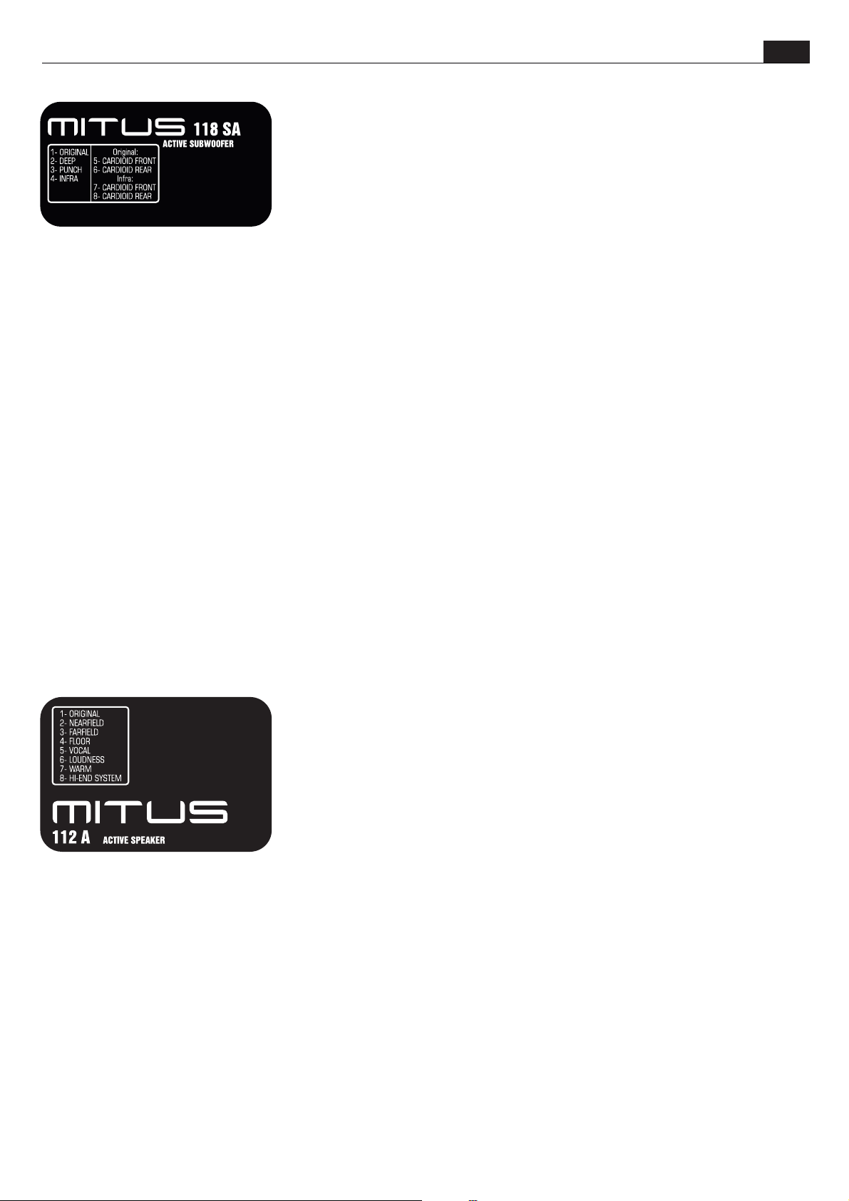
PRESET
-ORIGINAL: Corresponds to the typical FBT sound. It is the default general purpose preset
and is thus fit for the majority of applications.
-DEEP: This preset extends and emphasizes the low range of the subwoofer, for a very deep
and soft sound suitable for high quality and medium energy applications, such as acoustic
music, jazz, etc..
-PUNCH: the sound of the sub becomes drier, reduced low frequency extension but more
energy concentrated in the 80-120Hz range. Suitable for rock music and high SPL
applications
-INFRA: The filter is set to a lower frequency with respect to the other presets, thus only very
low frequencies are reproduced. Choose this preset in systems where the MITUS 212FSA (set
with the 'with infra' preset) and MITUS 118/121SA subwoofers are both present at the same time
ORIGINAL – below there are two presets for cardioid configuration with ORIGINAL equalization curve, i.e. by default suitable for
general purpose
-CARDIOID FRONT: Cardioid configuration, set this preset on the SUB oriented toward the audience
-CARDIOID REAR: Cardioid configuration, set this preset on the SUB oriented toward the stage (physically rotated 180° with respect to the
FRONT).
- The system is composed of two different SUBs, MITUS 212/FSA and MITUS 118SA or MITUS 121SA, all laid on the ground. This type of
system isrecommended when you want to use all the SUBs available in order to increase the SPL but the MITUS 212FSA cannot be flown.
The MITUS 118SA/121SASUB laid onthe ground hasto be configuredwith the INFRApreset.
INFRA – below there are two presets for cardioid configuration with INFRA equalization curve. Choose these presets in systems where the
MITUS 212FSA (set withthe 'with infra'preset) and MITUS118/121SAsubwoofers areboth present atthe same time
-CARDIOID FRONT: Cardioid configuration, set thispreset on theSUB oriented towardthe audience
-CARDIOID REAR: Cardioid configuration, set this preset on the SUB oriented toward the stage (physically rotated 180° with respect to the
FRONT).
UK
The presence of 8 DSP-managed presets permits to modify the speaker answer in a much more
accurate way with respect to tune controls. Moreover, presets are already designed and
optimized in ananechoic room togive the speakerthe desired character.
-NEARFIELD: Suitable for a very close listening, up to 7-8m. Recommended for small rooms or
with a veryclose audience wherea medium-high SPLis anyway required.
-FARFIELD: For listening to the speaker at a distance over 15-20m. Suitable when the sound
has to beprojected over longdistances.
-FLOOR: The speaker has specialized, and works as stage monitor. The answer is balanced to
take into accountthe proximity tothe floor andthe listening ofsounds in anear field.
-VOCAL: Permits obtaining top intelligibilityof spoken language even indifficult
environments or withhigh noise floor. The passbandis modified toemphasize vocal range.
-LOUDNESS: Typical answer curve for music application or record, with bass and treble
emphasized with respectto the middle frequencies that, instead, remainslightly in thebackground. This preset is very satisfying iflistened to
at low volumebut is alsosuitable for usingthe speaker indiscos and pubs.
-WARM;: Gives a dense sound quality on middle-low frequencies and a less aggressive quality on trebles. Suitable for broadcasting music
in very sound-absorbing environments or in situations that require a very strong sound at low frequencies and a sweet soundat middle-high
frequencies.
-HI-END SYSTEM: It is characterized by the typical answer of top class speakers that are exclusively designed for touring applications.
Therefore, very linear answer and passband without too much extension on the extremes. Those who are used to working with highly
professional audio systemswill find whatthey look forin this preset.
15
Page 19
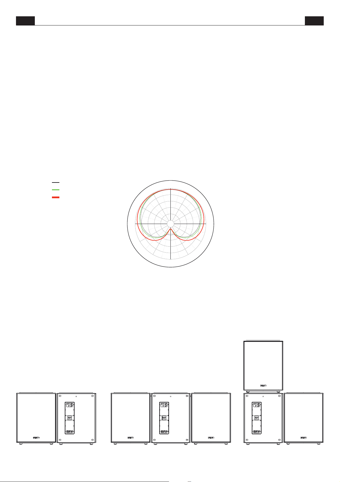
ITA UK
CONFIGURAZIONI CARDIOIDI
CARDIOID CONFIGURATIONS
La mancanza di direttività alle basse frequenze è un problema che tocca
molti sistemi di rinforzo sonoro; tale direttività può essere controllata
allineando array di subwoofers a radiazione diretta secondo pattern che
concentrano l’energia diffusa in unao più direzioni.
Come in ogni range di frequenze, la somma energetica tra due subwoofer
può portare a somme di 6dB cosìcome a cancellazioni complete ( quando le
onde sonore sono sfasate di 180° ). I tipici lobi del diagramma polare sono
causati dalla differenza del tempo di arrivo delle sorgenti sonore in una data
posizione.
Le configurazioni cardioidi sono utili per eliminare le basse frequenze sul
palco e diconseguenza migliorare riprese microfonichecritiche.
La configurazione cardioide permette di ottenere un pattern di distribuzione
dell’SPL prodotto dai subwoofer di tipo cardioide, riducendo la pressione
sonora nell’area posteriore. Questa configurazione è indicata quando è
necessario attenuare l’energia delle basse frequenze nel palco o in zone
dove non èdesiderata per motivi diinquinamento acustico.
Come si vede dal grafico, posteriormente all’emissione frontale si riesce ad
avere una attenuazione utile di circa 15-20dB in tutto il range di
funzionamento dei subwoofer( 30-130Hz ).
Horiz. f=40Hz
H or iz . f= 80H z, norm e d to 1
H or iz . f= 130 H z, no rm e d to 1
Per eseguire una configurazione cardioide è
+45°
+60°
+75°
+30°
+15°
necessario impiegare un sub puntato posteriormente
ogni due sub puntati frontalmente. Gran parte
+90°+90°
dell’energia prodottadal sub posteriore viene utilizzata
per cancellare l’energia prodotta dagli altri due sub
frontali, quindi l’SPL massimo complessivo dei 3 sub
nella zona frontale è di circa +1dB rispetto ad una
configurazione classica( noncardioide ); naturalmente la
configurazione cardioide funziona anche con un sub
FRONT e un sub REAR. Il posizionamento dei sub è molto
importante per avere la massima attenuazione posteriore. Le
+105°
+120°
+135°
+150°
+165°
figure illustrate in questa pagina mostrano le configurazioni da
utilizzare.
Alcuni preset della linea di sub MITUS sono dedicati alla configurazione
cardioide.
Nei subwooferposizionati frontalmentesettare il preset CARDIOID FRONT,
in quello ruotato di 180°( quindi posizionatoposteriormente) settareil preset
CARDIOID REAR.
Nei diffusori MITUS 118SAe MITUS 121SA le configurazioni cardioidi sono
disponibili con duediverse equalizzazioni: ORIGINAL ed INFRA.
The lack of directivity at low frequencies is a problem affecting many sound
reinforcement systems; this directivity canbe controlled by lining upan array
of direct radiation subwoofers according to patterns that concentrate
diffused energy inone or more directions.
As for all frequency ranges, the sum of the energy of two subwoofers can
lead to both 6db sums and complete cancelling (when the sound waves are
180° out of phase). The typical lobes of the polar diagram are caused by the
difference in thetime of arrival ofsound sources to aspecific position.
Cardioid configurations are useful to cancel low frequencies from the stage
and consequently toimprove critical microphone recordings.
The cardioid configuration enables a cardioid distribution of the SPL from
Subwoofers, reducing rearsound pressure.
It is perfect when the energy of low frequencies has to be attenuated, for
example on the stage or in areas where it should be avoided due to noise
pollution.
As you can see from the diagram, the attenuation achieved behind the front
sound emission is 15-20 db approximately for the whole subwoofer
operating range (30-130Hz)
0°
-15°
-30°
-45°
-60°
For this purpose, a rear sub shall be employed every
-75°
two front subs. The majority of the energy generated
by the rear sub is used to cancel the energy of the
364248546066 dB
+/-180°
-165°
-150°
-90°-90°
other twofront subs, so that the maximum overall SPL
-105°
of the 3 subs in the front area is equal to +1db
approximately compared to a typical (non cardioid)
-120°
configuration with twofront subs only.
-135°
Obviously, this configuration is valid also with a FRONT
sub and aREAR sub.
Subs position is very important in order to obtain the best
possible rear attenuation. Use the configurations showed in
picture.
Some presets of MITUS SUB range are specially dedicated to the cardioid
configuration.
Set the CARDIOID FRONT preset in front SUBS, and in the SUB rotated by
180° (hence, therear sub) set theCARDIOID REAR preset.
Two different equalizations are available for the cardioid configurations of
118Saand 121Sa subs: ORIGINALandINFRA.
FRONT
FRONT REAR FRONT REAR FRONT FRONTREAR
16
Page 20
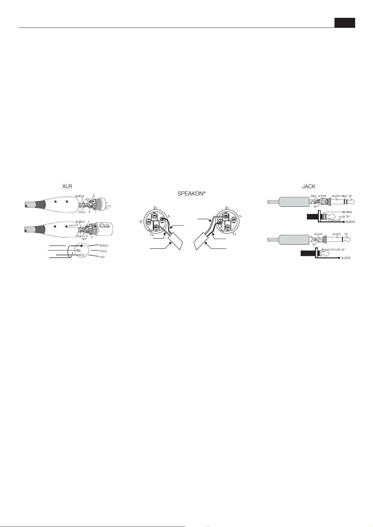
ITA
CONNECTORS
UK
I connettori hanno tre poli e vengono utilizzati quasi sempre per
XLR
condurre segnali mono bilanciati; i tre poli corrispondono
rispettivamente alla massa (1), al segnale positivo (2) e al segnale
negativo (3).
SPEAKON
è un connettore adatto appositamente per il
collegamento tra finali di potenza e altoparlanti; inserendolo
nell#apposita presa si blocca in modo da impedire un distacco
accidentale; inoltre è dotato di protezione contro scosse elettriche e
garantisce una correttapolarizzazione.
JACK
I sono connettori tipici per trasportare due segnali separati di
due canali, destro e sinistro, con un unico connettore e quindi
possono essere di tipo mono o stereo. I jack mono (TS), detti anche
sbilanciati, si differenziani da quelli stereo (TRS)m, o bilanciati, per
la loro composizione. I primi hanno lo spinotto diviso in due parti,
punta e massa (Tip e Slave), a cui sono collegati i due poli; i jack
stereo o bilanciati sono invece divisi in tre parti, in quanto hanno un
anello centrale (Ring) collegato ad un secondo filo che costituisce il
terzo polo (negativo).
maschio
male
femmina
female
schema
diagram
CONNESSIONEDIUSCITA STEREO CONNESSIONEDIUSCITA BRIDGE
STEREOOUTCONNECTION BRIDGEOUTCONNECTION
USCITANEGATIVA
NEGATIVEOUT
USCITAPOSITIVA
POSITIVEOUT
AL DIFFUSORE
TOSPKR
The 3-pole XLR connectors are almost always used for conducting
mono-balanced signals; the three poles correspond respectively to
ground (1), thepositive signal (2)and the negativesignal (3).
SPEAKON
is a connector which is specially adapted for connecting
power terminals to loudspeakers; when inserted in an appropriate
socket it locks so as to prevent accidental disconnection; moreover,
it is equipped with protection against electrical shocks and
guarantees the correctpolarisation.
JACKS
The are typical connectors for the transporting of two
separate signals through two channels, left and right, using a single
connector and therefore they can be either mono or stereo. Mono
jacks (TS) also known as unbalanced jacks, are recognisable from
stereo or balanced jacks (TRS) by their composition. The point of
the mono jacks is divided into two parts, tip and ground Tip and
Slave) to which the two poles are connected; the stereo or balanced
jacks are divided in three parts, as they have a central ring (Ring)
which is connectedto a secondwire, the third(negative) pole.
stereo
USCITAPOSITIVA
POSITIVEOUT
USCITANEGATIVA
NEGATIVEOUT
AL DIFFUSORE
TOSPKR
mono
schema
diagram
schema
diagram
17
Page 21
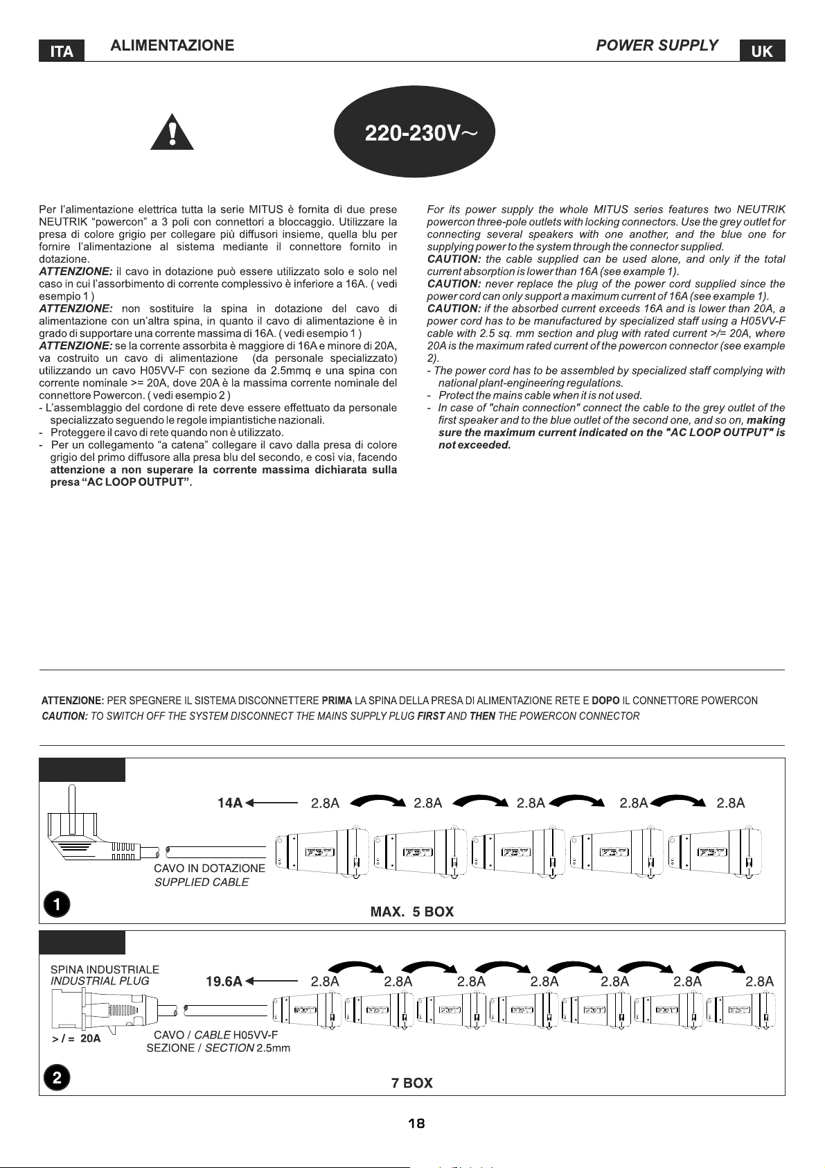
MAX. 16A
MAX. 20A
Page 22
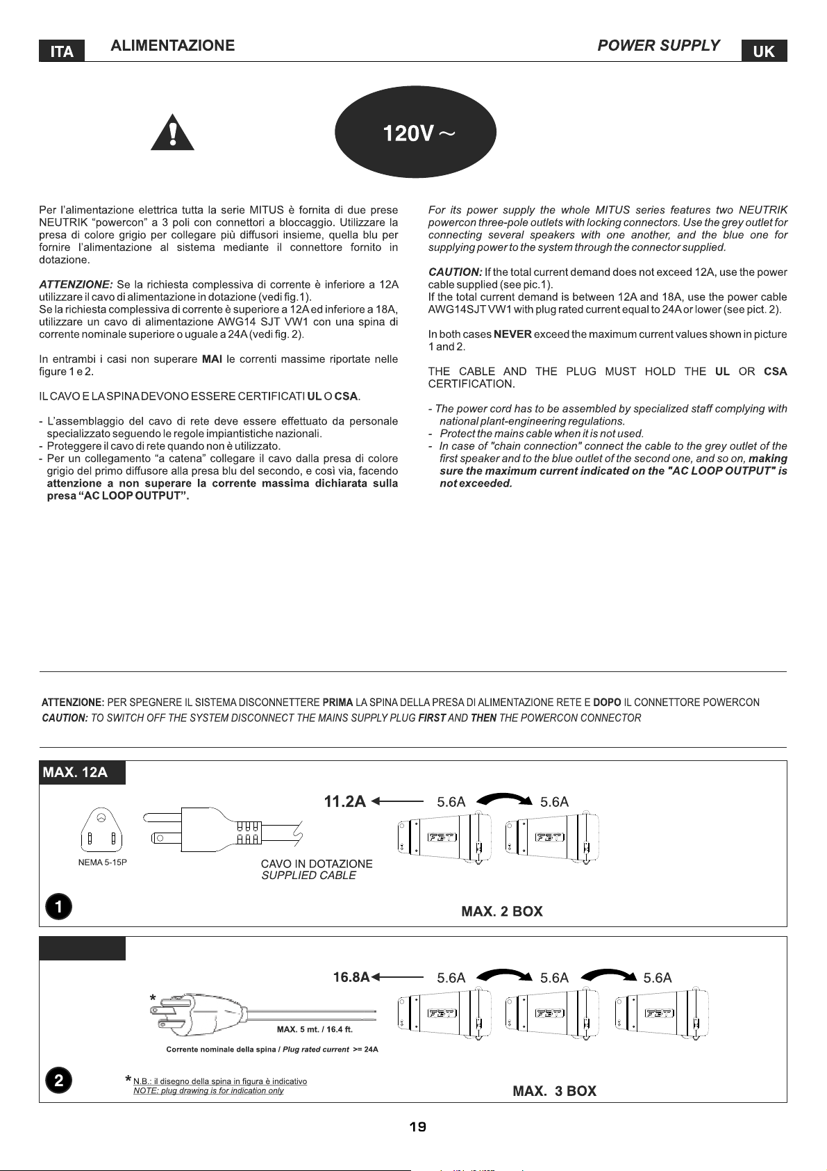
MAX. 18A
CORD TYPE SJT3 x 14 VW1
CORD TYPE SJT3 x 14 VW1
Page 23
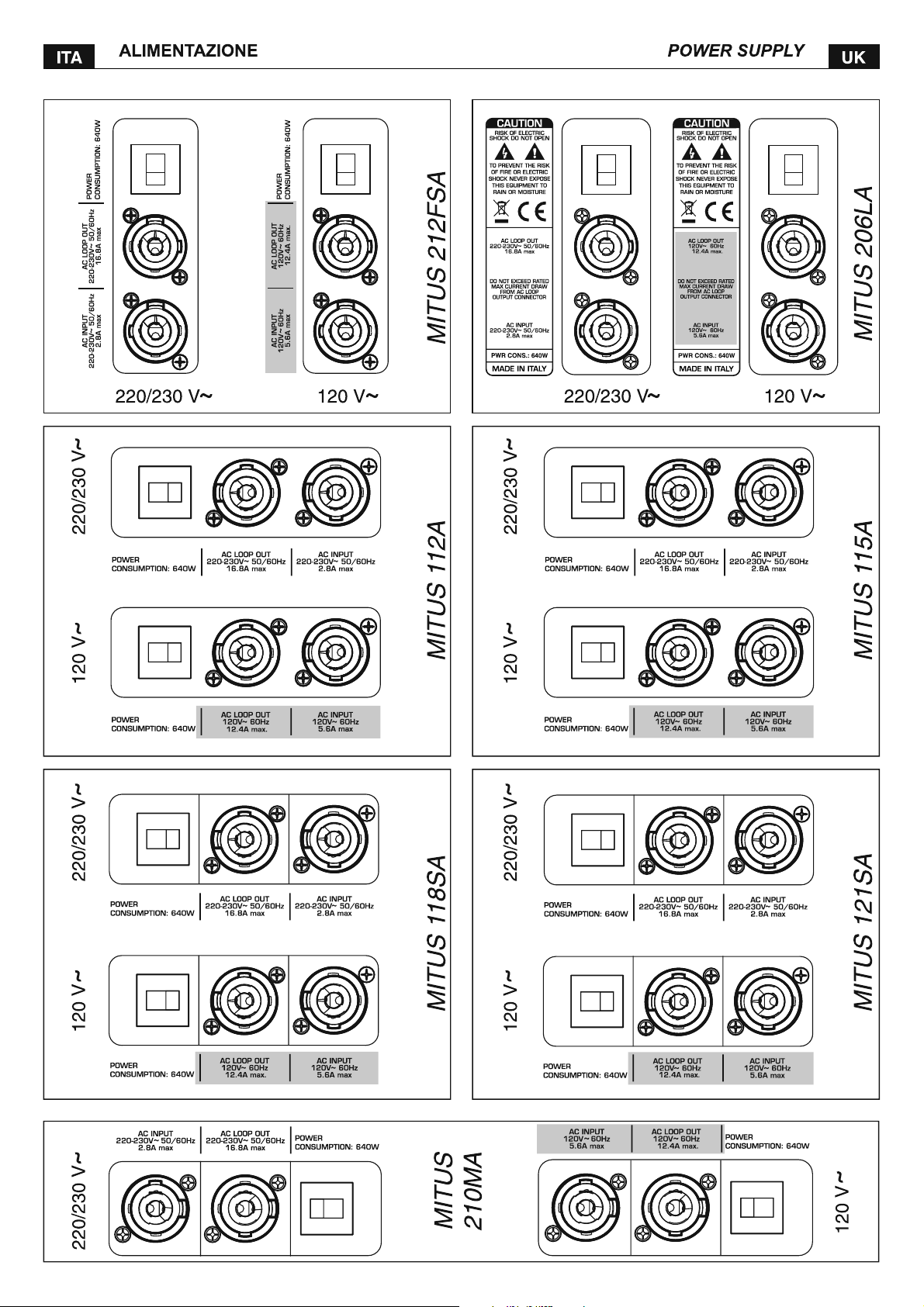
Page 24
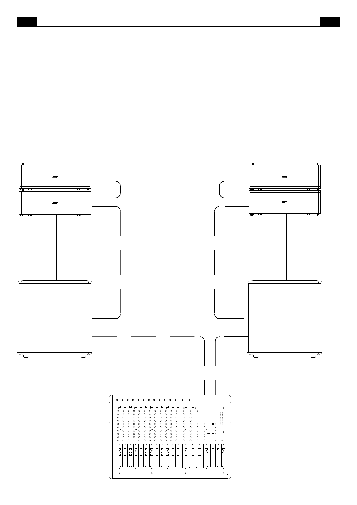
ITA UK
ESEMPIDIUTILIZZO
USAGEEXAMPLES
4xMITUS206LA+2xMITUS118SA
4000Wpotenzacontinua
136dB@1mt
110dB@22mt
250mq.con750persone
LEFT RIGHT
2xMITUS206LA 2xMITUS206LA
400W+200W
400W+200W
IN IN
LINK
IN IN
LINK
4000Wcontinuouspower
136dB@1mt
110dB@22mt
250mq.with750people
400W+200W
400W+200W
800W
MITUS118SA MITUS118SA
LINK LINK
IN IN
LR
800W
OUT
MIXER
20
Page 25
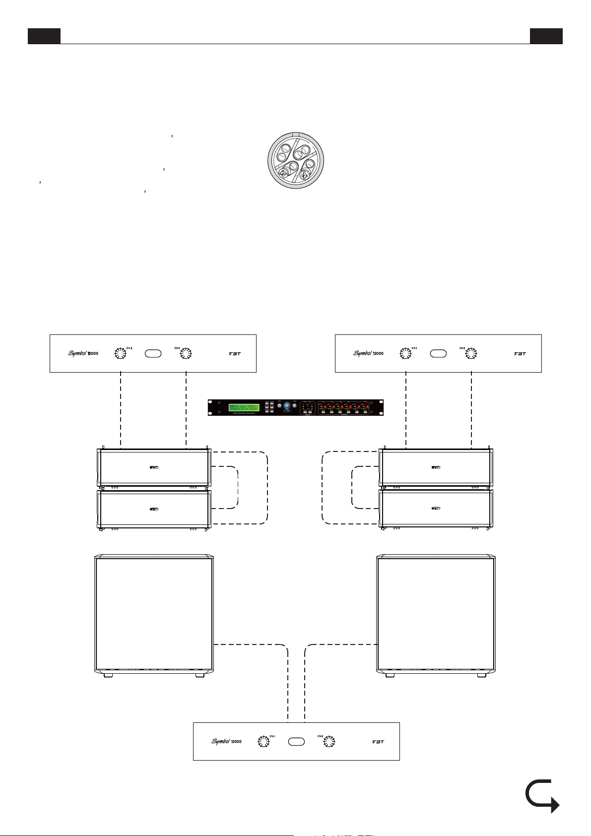
ITA
CONFIGURAZIONE IN BIAMP
4 x MITUS 206L + 2 x MITUS 118S
BIAMP CONFIGURATION
UK
Il sistema Bi-Amp prevede l utilizzo di un
amplificatore stereo; in pratica si possono
collegare i cavi del tweeter ad un canaledel finale
di potenza e quellidel woofer all altro garantendo
un alta fedeltà del suono, un maggior dinamismo
e un sensibile aumentodell SPL.
UNITÀ DI POTENZA
POWER UNIT
1-
1+
2+
2-
SPEAKON
The Bi-amp system requires a stereo amplifier;
basically it is possible to connect the tweeter
cables to one of the channels of the main
amplifier and the woofer cables to the other one,
thus guaranteeing high sound fidelity, higher
dynamism and a significantSPL increase.
UNITÀ DI POTENZA
POWER UNIT
LEFT RIGHT
HF LF
2 x MITUS 206L
MITUS 118S MITUS 118S
PROCESSORE
PROCESSOR
LINK LF
LINK HF
LINK LF
HF LF
LINK HF
2 x MITUS 206L
UNITÀ DI POTENZA
POWER UNIT
21
Page 26
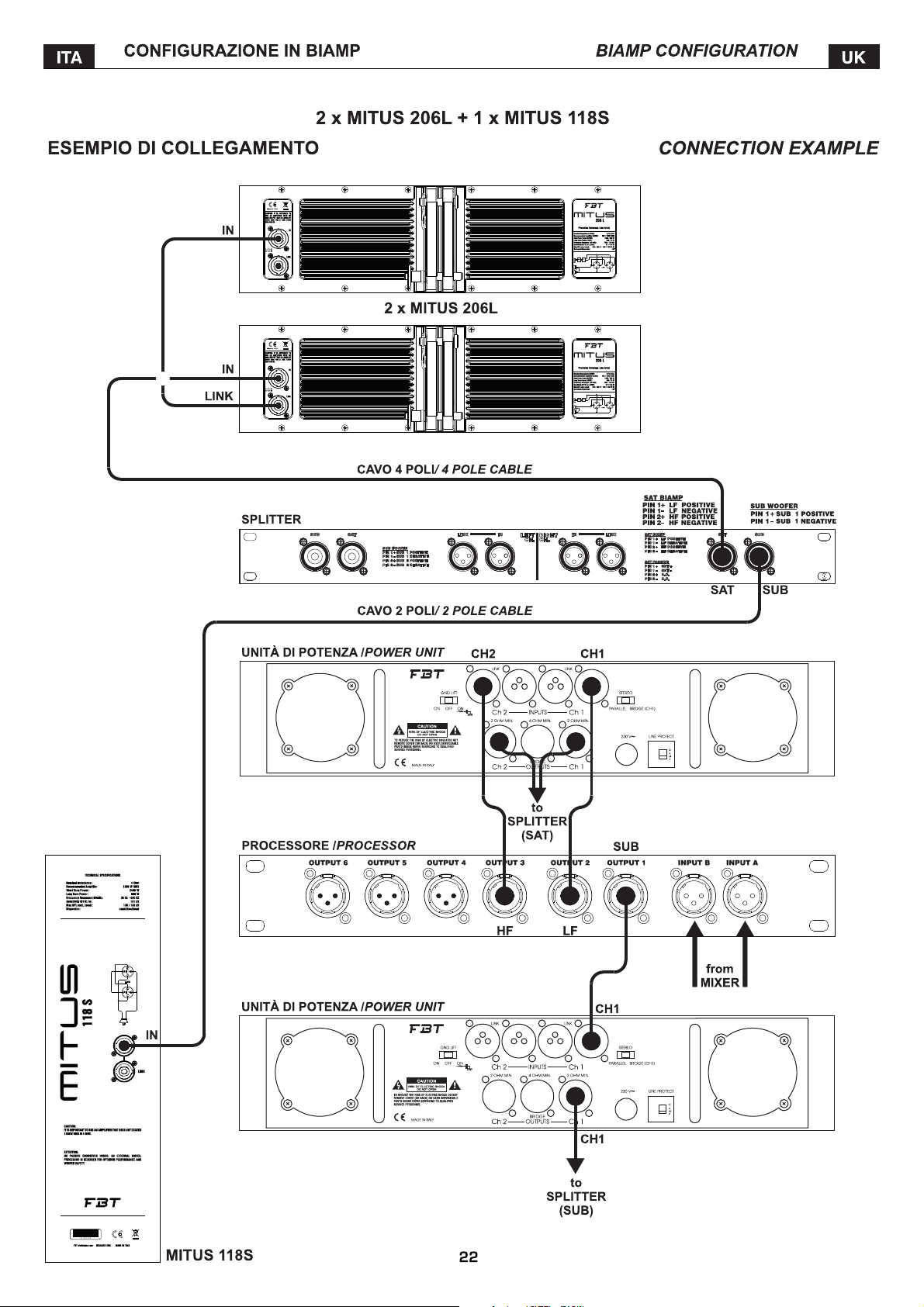
Sound Reinforcement Subwoofer
PLEASEREFERTO OWNER!S MANUALFOR SETTINGS.
Page 27
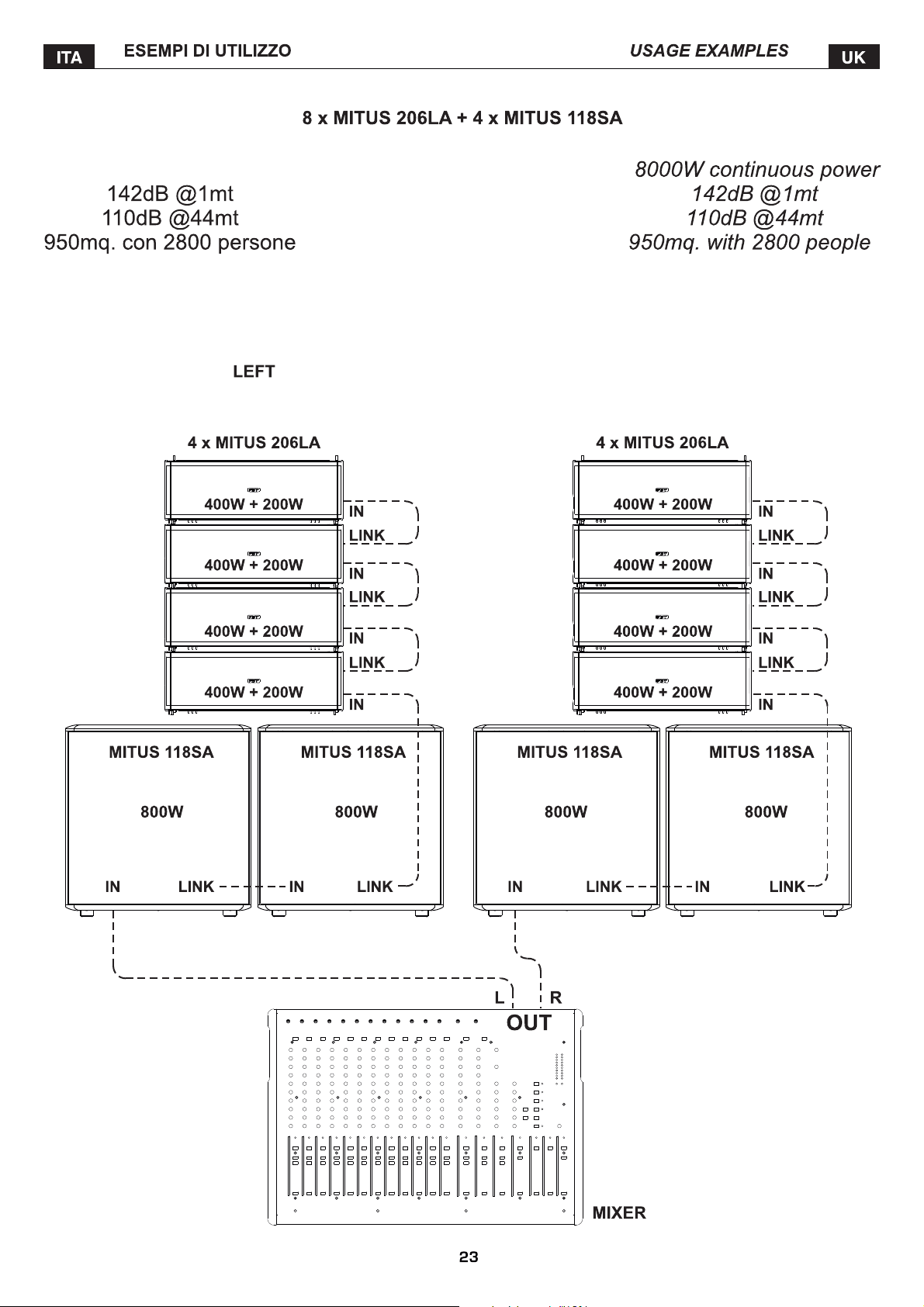
8000W potenza continua
RIGHT
Page 28

4 x MITUS 212 FSA + 24 x MITUS 206LA + 4 x MITUS 121SA + 8 x MITUS 118SA
CHANNEL
121SA
Page 29

Page 30

Page 31

Page 32

Page 33

safety locking device Ø 1.38" M20
Page 34

Il sistema MITUS è conforme alla normativa EN 60065 per la
> Do notuse damaged or wornmaterials
Page 35

Nelle figure riportate in questa pagina sono rappresentate le
della FBT:www.fbt.it
Page 36

1
B
A
2
C
BARRA DI CONNESSIONE
CONNECTION BAR
C
32
Page 37

3
D
E
33
Page 38

Page 39

Page 40

ITA UK
MONTAGGIO DELLA BARRA DI SICUREZZA MT-A206
ASSEMBLY OF THE MT-A206 SAFETY BAR
QUESTO ACCESSORIO VA MONTATO SULL’ULTIMO
DIFFUSORE AGGANCIATO PER ASSICURARE
TUTTO IL SISTEMA MEDIANTE FUNI ED EVITARNE
LAROTAZIONE E L’OSCILLAZIONE.
MOUNT THIS ACCESSORY ON THE LAST SPEAKER
HOOKED IN ORDER TO SECURE THE WHOLE
MT-A206
SYSTEM BY MEANS OF ROPES AND PREVENT IT
FROM ROTATING AND OSCILLATING.
1
Fori per il passaggio delle funi di sicurezza.
Holes for the passage of safety ropes.
3
2
Page 41

mm 660x280x460 785x520x710 640x760x780 700x940x800 490x750x490 560x860x550 675x395x510
36
Page 42

Page 43

38
Page 44

39
Page 45

Page 46

FRA DE
|
|
|
<
ATTENTION
RISQUEDECHOCÉLECTRIQUE
NEPASOUVRIR
!
|
|
|
<
VORSICHT
STROMSCHLAGGEFAHR
NICHTÖFFNEN
!
POURÉVITERLERISQUEDECHOCÉLECTRIQUE
NEPASUTILISERD’OUTILSMÉCANIQUESÀL’INTÉRIEUR
CONTACTERUNCENTRED’ASSISTANCEQUALIFIÉ
POURÉVITERLERISQUED’INCENDIEOUDECHOCÉLECTRIQUE
NEPASEXPOSERL’APPAREILLAGEÀLA PLUIEOUÀL’HUMIDIT
|
|
|
<
!
NEPASOUVRIRLECOUVERCLE
CE SYMBOLEPRÉVIENT,LÀ OÙ ILAPPARAÎT, DELA PRÉSENCED'UNE
TENSION DANGEREUSENON ISOLÉEÀ L'INTÉRIEURDE LACAISSE:
LE VOLTAGE PEUTÊTRE SUFFISANTPOURREPRÉSENTER
UN RISQUEDE DÉCHARGESÉLECTRIQUES.
CE SYMBOLE PRÉVIENT, LÀ OÙ IL APPARAÎT, DE LA PRÉSENCE
D'IMPORTANTES NOTICES DE MODE D'EMPLOI ET CONCERNANT
L'ENTR ETI EN DANS LA DOC UME NTATION JOI NTE. VE UILL EZ
CONSULTERLE MODE D'EMPLOI.
INFORMATIONSDESÉCURITÉIMPORTANTES
1) Lisez cesinstructions
2) Conservez cesinstructions
3) Faites attentionà tous les avertissements
4) Suivez toutesles instructions
5) N'employez pasce dispositif près de l'eau
6) Ne nettoyezqu'avec un torchon sec
7) N’obstruez pas les ouvertures de la ventilation. L’installation doit
être effectuée selon les instructions fournies parle producteur.
8) Ne l'installez pas près de sources de chaleur comme radiateurs,
appareils de chauffage, poêles ou d'autres appareils (y compris les
amplificateurs) qui produisentde la chaleur
9) Ne supprimezpas les dispositifsde sécurité des fiches polarisées ou
avec mise à la terre. Les fiches polarisées sont équipées de deux
bornes de largeur différente. Une fiche avec mise à la terre a deux
bornes et un troisième pôlede terre. La borne plus large ou letroisième
pôle sont nécessaires pour la sécurité de l'utilisateur. Si la fiche fournie
n'est pas appropriée pour votre prise, consultez un électricien pour le
remplacement de lafiche.
10)Protégez le câble d'alimentation du piétinement et de la
compression, en particulier où l'on trouve des fiches, des rallonges et
dans le pointoù ils sortent de l'appareil.
11) Employez uniquement des dispositifs en option/accessoires
indiqués par leproducteur.
12) A employer uniquement avec des chariots, des
supports, des trépieds, des consoles ou des tables
indiqués par le producteur ou vendus avec l'appareil.
Si vous utilisez un chariot, faites attention pendant le
déplacement contemporain du chariot et de l'appareil,
afin d'éviter des dommages dus au possible
renversement.
13) Débranchez la fiche en cas d'orage ou lorsqu'on n'utilise pas
l'appareil pendant unelongue période.
14) Pour l'assistance technique, adressez-vous au personnel qualifié.
L'assistance technique est nécessaire au cas où l'appareil est
endommagé, par ex. à cause de problèmes du câble d'alimentation ou
de la fiche, du renversement de liquides oud'objets tombés à l'intérieur
de l'appareil, de l'exposition à la pluie ou à l'humidité, d'anomalies de
fonctionnement ou dechutes de l'appareil.
L’APPAREILDOIT ÊTRE CONNECTÉ AU RÉSEAU ÉLECTRIQUEPAR
UNE PRISE AYANTUNE CONNEXION DE PROTECTIONDE TERRE .
STROMSCHLAGGEFAHRNICHTDENDECKEL ÖFFNEN
WENDENSIESICHANEINENQUALIFIZIERTENKUNDENDIENST
UMRISIKENVONSTROMSCHLAGUNDBRANDAUSZUSCHLIESSEN
SETZENSIEDASGERÄTKEINEMREGENODERFEUCHTIGKEITAUS
DIESES SYMBOL VERWEIST AUF DIE PRÄSENZ EINER GEFÄHRLICHEN
NICHT ISOLIERTEN SPANNUNG IN DER LAUTSPRECHERBOX: DIE
|
|
S PA N NUN G K ANN GEN Ü GE ND STA RK SE I N , U M E IN E
|
STROMSCHLAGGEFAHRDARZUSTELLEN.
<
DIESES SYMBOL VERWEIST AUF WICHTIGE HINWEISE IN
D EN M I T G E L IE F E RT E N B E D I EN U N GS - U N D
WARTUNGSANLEITUNGEN. ZIEHEN SIE DAS HANDBUCH
!
ZU RATE.
WICHTIGESICHERHEITSHINWEISE
1) Lesen Siediese Anleitungen aufmerksam durch.
2) Bewahren Siesie sorgfältig auf.
3) Beachten Siealle Hinweise.
4) Halten Siesich an sämtliche Anleitungen.
5) Verwenden Sie diesesGerätnicht in derNähe von Wasser.
6) Reinigen Siees nur mit einemtrockenen Lappen.
7) Die Lüftungsöffnungen nicht verstellen. Die Installation muss
entsprechend der vomHerstellergelieferten Anleitung erfolgen.
8) Vermeiden Sie es, das Gerät in der Nähe von Wärmequellen, wie
Heizkörper, Heizrohre, Öfen oder anderen wärmeerzeugenden Geräte
(auch Verstärker) aufzustellen.
9) Achten Sie darauf, die Sicherheitsfunktion der polarisierten oder
geerdeten Steckern nicht aufzuheben. Polarisierte Stecker haben zwei
flache Stifte, einer davon ist breiter alsder andere.Ein geerdeter Stecker
hat zwei Stifte und einen Erdungsstift. Ein geerdeter Stecker hat zwei
Klinken und einen Erdungsstift. Der breitere Stift bzw. der dritte Stift
dienen Ihrer Sicherheit. Sollte der mitgelieferte Stecker nicht in Ihre
Steckdose passen, lassenSie ihn durch einenElektriker auswechseln.
10) Schützen Sie das Stromkabel vor Tritt- und Druckeinwirkungen,
insbesondere im Bereich der Stecker, von Verlängerungen und beiihrem
Austritt aus demGerät.
11) Verwenden Sie ausschließlich vom Hersteller empfohlene
Zusatzgeräte/Zubehörteile.
12) Benutzen Sie ausschließlich vom Hersteller
empfohlene oder mit dem Gerät verkaufte Wagen,
Ständer, Stative, Halterungen oder Tische. Achten Sie
bei Verwendung eines Wagens darauf, dass das darauf
stehende Gerät während der Fahrt nicht umkippt und
Schaden erleidet.
13) Stecken Sie das Gerät bei Gewittern oder längerer
Außerbetriebsetzung bitte ab.
14) Für den technischen Kundendienst wenden Sie sich bitte
auss chließlich an q ualifiziertes Pers onal. Ein technischer
Kundendiensteinriff wird erforderlich, wenn das Gerät auf irgendeine
Weise beschädigt wird, z.B. durch Schädenam Netzkabel oder -stecker,
durch Eintreten von verschütteten Flüssigkeiten oder Gegenständen,
durch Regen oder Feuchtigkeit, durch Hinunterfallen, oder bei
Funktionsstörungen.
DAS GERÄT ÜBER EINE GEERDETE STECKDOSE AN DAS
STROMNETZ ANSCHLIESSEN.
Cet appareil est équipé d’une prise d’alimentation; installez l’appareil
de façon à ce que la prise du câble d’alimentation soit facilement
accessible.
PRÉCAUTIONS
° Afin de permettre une ventilation suffisante il faut disposer une
distance min. de30cm. environ de tous les côtés del’appareil.
° La ventilation ne doit pas être empêchée en couvrant les ouvertures
d’aération avec desobjets comme journaux, nappes, rideaux, etc.
° Aucune source à flamme nue, comme par exemple des bougies
allumées, ne doitêtre posée sur cet appareil.
° L’appareil ne doit pas être exposé à la stillation ou aux jets d’eau et
donc il ne faut pas poser sur le dispositif des objets contenant des
liquides, comme parexemple des vases.
Dieses Gerät ist mit einer Steckdose ausgestattet. Installieren Sie das
Gerät so, dass die Steckdose des Stromkabels leicht zugänglich
resultiert.
VORSICHTSMAßNAHMEN
° Hierzu muss um alle Geräteseiten herum eine Mindestdistanz von 30
cm berücksichtigt werden.
°
Behindern Sie die Ventilation keinesfalls durch Abdecken der
Lüftungsöffnungen mit Zeitungen, Tischtüchern,Vorhängen usw.
°
Keine offenen Flammen, beispielshalber brennende Kerzen, auf das
Gerät stellen.
°
Das Gerät ist unbedingt vor Tropfen oder Wasserspritzern zu
schützen. Stellen Sie also keinesfalls Flüssigkeitsbehälter, wie
beispielsweise Blumenvasen darauf.
.
1
Page 47

FRA
La série de sonorisation représente le résultat de l'expérience et de
la passion pour la perfection de FBT. Il s'agit d'une gamme complète de
diffuseurs 2 voiespourapplication FOH, subwoofers,moniteur de plateauet
« line array », en version bi-amplifiée et passive. Lors de leur emploi pour
des performances « live », en tournée ou en installation fixe, ils seront
appréciés par tout musicien et professionnel étant à la recherche de la
meilleure qualité duson.
MITUS 206LA
woofers de 165mm et un driver avec bouche de 36mm couplé à un guide
d'onde, conçu pourrespecter les critèresphysiques de la source cylindrique
idéale dans toute la portée audio. Avec son boîtier en polypropylène à
injection de gaz et samécanique desuspension intégrée, MITUS 206LA est
un grand résultat de l'élaboration mécanique et électronique de FBT. Par le
logiciel de visée de FBTpour les ordinateurs, on peut simuler la distribution
de SPL et laréponse en fréquence dansla zone d'écoute.
MITUS 212FSA
mécanique de suspension intégrée, étant parfait pour étendre les basses
fréquences du MITUS 206LAen configuration « line array » suspendue ou
par terre.
Les modèles et , ayant respectivement un
woofer de 460mm et un de 530mm, complètent la gamme de subwoofers ;
ils s'intègrentparfaitement avec les satellites MITUS lors des performances
« live »ou pour lesinstallations fixes, enrenforçant et enétendant la gamme
basse avec le SPL élevé qu'ils offrent. Ils sont tous en multicouches de
bouleau avec peinturenoire antirayures.
MITUS 115A MITUS 112A
bons pour une vaste gamme d'applications, en particulier s'ils sont couplés
aux subs MITUS. Ils assurent une qualité sonore étonnante lors de
performances « live»ou dans lesinstallations fixes.
MITUS 210MA
moniteur de plateau le plus avancé du point de vue technologique dans sa
classe ; deux woofers de 250mm, dont un est coaxial, avec un driver de
36mm, assurent une fidélité très haute et une réserve dynamique pour
toutes les performances«live » oules programmes TV.
Toute la sérieMITUSest équipée de:
- haut-parleurs B&CcustomFBT au néodymedequalité très élevée;
- driver àcompressionB&C de dernièregénération ;
- module amplificateur en classe D à haute efficacité avec alimentateur de
type « switching » mis en boîte dans une enveloppe sous pression en
aluminium.
- processeur de signal numérique DSP avec convertisseurs A/D - D/A au
bruit très faible;
- connecteurs d'alimentationNeutrik Powercon « inet loop out »;
- grande disponibilité d'accessoires et d'arrangements qui rendent la
gamme MITUS trèsflexibleet simple àemployer ;
- nouvelle poignée sous pression en aluminium avec une pièce en
caoutchouc permettant uneprisesure et confortable;
- filet frontal robuste et anti-résonnant avec l'emploi d'un tissu synthétique
de protection inédit.
INTRODUCTION
MITUS
est le modèlede pointe dela gamme ; un « line array »avec 2
est un subwoofer de 2x320mm, compact, avec une
MITUS 118SA MITUS 121SA
et sont desdiffuseurs bi-amplifiés FOH à 2 voies
, avec son profil bas et élégante, est sans aucun doute le
EINLEITUNG
MITUS
Die -Serie entsteht aus der Erfahrung und der Leidenschaft für die
Perfektion von FBT. Eine komplette Serie von 2-Wege Lautsprechern für
FOH-Anwendungen, Subwoofers, Bühnenbildschirm und Line Array in 2fach verstärkter und passiver Ausführung.Ob bei Lives, Touring oder festen
Installierung, werden diese sicherlich die Zustimmung der Musiker und der
Profis finden, dieauf der Suche nachder besten Soundqualität sind.
MITUS 206LA
Woofer und Treiber mit 36-mm-Öffnung und mit einem Wellenleiter
gekoppelt. Entwickelt,um die physischen Kriterien der zylindrischen Quelle
zu bewahren und ideal für den gesamten Tonbereich. Polypropylen-Kasten
mit Gaseinspritzung und eingebauter Hängemechanik. MITUS 206LA ist
ein hervorragendes Ergebnis mechanischer und elektronischer
Entwurfsbearbeitung von FBT. Mit Hilfe des FBT Aiming Software für den
Rec hner, kön n en die Sch alld ruck p ege l ver t eil u ng und das
Frequenzverhalten im Zuhörbereichsimuliert werden.
MITUS 212FSA
Hängemechanik. Ideal zur Erweiterung der niedrigen Frequenzen des
MITUS 206LA in Hänge-oder Boden-Line Array Konfiguration.
Die Subwoofer und , je mit 460mm und
530mm Woofer, vollenden die Subwoofer Serie. Diese integrieren sich
perfekt mit den MITUS Satelliten beim Live oder bei fester Installierung und
Erweitern, dank des hohen erreichbaren SPL, den Tieftonbereich.Alle sind
aus Mehrschicht-Birkenholz mitkratzfester schwarzer Lackierung gebaut.
MITUS 115A MITUS 112A
Lautsprecher und dienenfür viele Anwendungen, besonders zusammenmit
den MITUS Sub. Sie gewährleisten erstaunende Tonqualität bei
Liveveranstaltungen oder festenInstallierungen.
Das niedrige und elegante Profil machen aus sicher den
technologisch meist entwickelten Bühnenbildschirm seiner Kategorie. Zwei
250mm Woofer, davon einer koaxial, mit 36mm Treiber, versichern höchste
Wiedergabetreue und Dynamikreserve für alle Live- oder TV übertragenen
Vorführungen.
Die gesamte MITUSSerie verfügt über:
-Hochwertige B&C-Lautsprecher customFBT mit Neodymmagnet;
-Hochmoderner Kompressionsdriver B&C;
-Stark leistungsfähiges Verstärker Modul in Klasse D mit eingekapseltem
Switching-Netzgerät aus Aluminiumdruckgussgehäuse.
-DSP-Digitaler Signalprozessor mit A/D - D/A Wandler bei niedrigstem
Geräuschpegel;
-Neutrik Powercon Netzstecker„Eingang und Loop imAusgang“;
-Höhe Verfügbarkeit an Zubehör und Vorrüstungen, die die MITUS Serie
extrem anpassungsfähig undeinfach zu gebrauchen macht.
-Neuer Griff aus Aluminiumdruckguss mit Gummieinsatz für einen sicheren
und komfortablen Halt;
-Starkes Antiresonanz-Stirnnetz dank eines neuem, schützenden
Kunstgewebe.
ist das Spitzenmodellder Serie; einLineArray mit 2165-mm-
ist ein 2x320mm Subwoofer mit eingebauter
MITUS 118SA MITUS 121SA
und sind 2-fach verstärkte 2-Wege FOH-
MITUS 210MA
DE
MODULE AMPLIFICATEUR
Les systèmes actifs MITUS présententun module amplificateur en classeD
à haute efficacité avecalimentateur de type « switching » mis en boîte dans
une enveloppe souspression en aluminium.
Cette enveloppe permet de protéger la partie électronique de la poussière,
d'éviter touteperte d'airdes contrôles qui causerait des bruits ennuyeux, de
maximiser la dissipation de la chaleur en exploitant même la ventilation du
woofer et enévitantl'emploi de ventilateursde refroidissement.
Cela a permisdeconstruire un amplificateurde 1200W très léger.
Dans lesmodèles 206LA/206L, ce module joue même le rôle de bâti pour la
suspension et permetleréglage de l'angled'inclinaison.
VERSTÄRKER MODUL
Die aktiven MITUSSysteme verfügen überein Verstärker Modul inKlasse D
m i t e i n g e k a p s e l t e m S w i t c h i n g - N e t z g e r ä t a u s
Aluminiumdruckgussgehäuse.
Dies schützt die Elektronik vor Staub, vermeidet Luftverlust an den
Regelungen, der lästigen Lärm produzieren würde, und maximiert den
Wärmeverlust, indem auch die Wooferlüftung genutzt wird und zusätzliche
Abkühlräder vermieden werden.
All dies erlaubtedie Verwirklichung eines sehr leichten1200W Verstärkers.
Bei den Modellen 206LA/206L dient das Modul auch als Tragestruktur für
dieAufhängung und ermöglichtdie Einstellung des Neigungswinkels.
2
Page 48

FRA DE
CARACTÉRISTIQUESGÉNÉRALES
ALLGEMEINE MERKMALE
206LA 206L
Système « linearray» à 2voies compact :
> 2 wooferB&Cau néodyme de165mm avec bobine de44mm.
> Driver B&Caunéodyme avec bouchede 36mm et bobinede 64mm.
> Réponse enfréquencede 68Hz à20kHz.
> Amplificateurs classe D de 600W RMS pour LF et 300W RMS pour HF,
avec alimentateur detype« switching ».
> Processeur DSPavec 8 presets,niveau de HF réglable de+/- 5dB pourun
procédé « amplitudeshading » précis.
> Panneau de commande avec entrée XLR et connexion, volume, presets,
niveau HF,filtreHP, groundlift.
> Guide d'onde avec 100° de dispersionhorizontale avec front d'onde plane
jusqu'à 18kHz.
> Boîtier robuste en polypropylène à injection de gaz avec sa mécanique
intégrée pour la suspension et angulations réglables entre 0° et 10° à pas
de 2°.
> Vaste gamme d'accessoires pour des configurations suspendues ou
posées au soldirectementou au-dessus dessubwoofers MITUS.
> Très léger,seulement 14kg.
Versionpassive :
> Amplificateur recommandé 500W RMS / 16 Ohm BF et 150W RMS / 16
Ohm HF.
> Protection passiveinternepour le driverHF.
> Connecteurs SpeakonNL4 IN & LINK.
> DSP externe avecpreset FBT nécessaire.
LE MODÈLE MITUS 206L NE DISPOSE PAS DE CROISEMENT
PASSIF INTERNE ; LA CONNEXION SANS PROCESSEUR AVEC
L'UNITÉ DE PUISSANCEENDOMMAGELE DIFFUSEUR.
Kompaktes 2-Wege Line Array System:
> 2 B&C-Woofer165mm mit Neodymmagnet undeiner 44-mm-Spule.
> B&C-Driver mit Neodymmagnet mit 36-mm-Öffnung und einer 64-mm-
Spule.
> Frequenzgrad von68Hz bis 20kHz
> Verstärker in Klasse D 600W RMS für LF und 300W RMS für HF, mit
Switching-Netzgerät.
> DSP Prozessor mit 8 Voreinstellungen, HF-Pegel einstellbar von +/- 5dB
für eine sorgfältige„Amplitudenformung“.
> Bedienfeld mit XLR Input und Link, Volumen, Voreinstellungen, HF-
Pegel, HP-Filter, Ground Lift.
> 100° horizontal Streuung Wellenleiter mit flacher Wellenfront bis zu
18kHz.
> Starkes Polypropylen-Gehäuse mit Gaseinspritzung und eingebauter
Hängemechanik undeinstellbarer Neigungzwischen 0°und 10°, Schritte
je 2°.
> Große Auswahl an Zubehör für hängende oder auf dem Boden oder den
Subwoofern MITUS stehendenKonfigurationen.
> Sehr leicht,nur 14 kg.
PassiveAusführung:
> Empfohlener Verstärker 500W RMS / 16 Ohm LF und 150W RMS / 16
Ohm HF.
> Interner passiverSchutz für den HFTreiber.
> Speakon SteckerNL4 IN & LINK.
> Externer DSPmit FBTVoreinstellungnotwendig.
DAS MODELL MITUS 206L VERFÜGT NICHT ÜBER INTERNEM
PASSI V E N C ROSS O VER; D E R ANSCH L USS MIT DER
LEISTUNGSEINHEIT OHNE PROZESSOR, BESCHÄDIGT DEN
!!
LAUTSPRECHER.
212FSA 212FS
Subwoofer passe-bande compact, même largeur et matériel de
suspension du modèleMITUS206 :
> 2 woofers B&C custom au néodyme de 320mm à haute amplitude avec
bobine de 75mm.
> Réponse enfréquencede 45Hz à120Hz.
> Amplificateurs en classe D de 1200 W RMS avec alimentateur de type «
switching ».
> Processeur DSPavec 8presets, configuration cardioïde,délai.
> Panneau de commande avec entrée XLR et connexion, volume, presets,
délai, phase 0°-180°,ground lift.
> Boîtier enmulticouchesde bouleau de15mm avec peinture antirayures.
> C'est parfait pour étendre et renforcer les basses fréquences du modèle
MITUS 206 enconfigurationaussi bien suspendueque posée au sol.
> Support pourstatifM20.
Versionpassive :
>Amplificateur recommandé 1000W RMS/ 8 Ohm.
> Connecteurs SpeakonNL4 IN & LINK.
> DSP externe avecpreset FBT nécessaire.
LE MODÈLE MITUS 212FS NE DISPOSE PAS DE CROISEMENT
PASSIF INTERNE ; LA CONNEXION SANS PROCESSEUR AVEC
L'UNITÉ DE PUISSANCEENDOMMAGELE DIFFUSEUR.
210 MA
Système à 2voiesbi-amplifié avec deuxwoofers :
> Woofer coaxial B&C custom au néodyme de 250mm avec bobine de
64mm, driver de36mmavec bobine de64mm.
> WooferB&Cau néodyme de250mm avec bobine de64mm
> Réponse enfréquencede 60Hz à20kHz.
> Amplificateurs classe D de 600W RMS pour BF et 300W RMS pour HF,
avec alimentateur detype« switching ».
> Processeur designalnumérique DSP avec8presets d'égalisation.
> Panneau de commande avec entrée XLR et connexion, volume, preset,
filtre HP, ground lift.
> Dispersion conique70°.
> Boîtier à bas profil en multicouches de bouleau de 15mm avec peinture
antirayures.
> Il peut être employé même avec haut-parleur FOH grâce au support pour
statif de 35mm.
> Très léger,seulement 19kg.
Versionpassive :
>Amplificateur recommandé 800W RMS/ 4 Ohm.
> Croisement passifinterneavec protection «soft trip » surWF et TW.
> Connecteurs SpeakonNL4 IN & LINK.
Kompakter Bandpass Subwoofer, gleiche Breite und Hängestruktur
wie bei demModellMITUS 206:
> 2 Hochleistungs-B&C-Woofer 320mm mit Neodymmagnet und einer 75-
mm-Spule.
> Frequenzgrad von 45Hzbis 120kHz
> 1200 WRMS Verstärker in Klasse Dmit Switching-Netzgerät.
> DSP Prozessor mit 8Voreinstellungen,kardioide Konfiguration, Delay.
> Bedienfeld mit XLR Input und Link, Volumen, Voreinstellungen, Delay,
Phase 0° -180°, Ground Lift.
> Kasten aus 15mm Mehrschicht-Birkenholz mit kratzfesterLackierung.
> Ideal für die Erweiterung und Stärkung der niedrigen Frequenzen des
Modells MITUS 206in beiden Ausführungen, hängend odergestützt.
> Stativhalterung M20.
PassiveAusführung:
> Empfohlener Verstärker 1000W RMS/ 8 Ohm.
> Speakon Stecker NL4IN & LINK.
> Externer DSP mit FBTVoreinstellungnotwendig.
DAS MODELL MITUS 212FS VERFÜGT NICHT ÜBER INTERNEM
PASSIV E N C ROSSO V ER; DER A NSCHL U SS MIT DER
LEISTUNGSEINHEIT OHNE PROZESSOR, BESCHÄDIGT DEN
LAUTSPRECHER.
!!
210 M
2-fach verstärktes 2-Wege System mitzwei Woofer:
> Koaxial-B&C-Woofer custom 250mm mit Neodymmagnet und einer 64-
mm-Spule, 36mm Treiber miteiner 64-mm-Spule.
> B&C-Woofer 250mmmit Neodymmagnet und einer64-mm-Spule
> Frequenzgrad von60Hz bis 20kHz
> Verstärker in Klasse D 600W RMS für LF und 300W RMS für HF, mit
Switching-Netzgerät.
> DSP Prozessor mit8 Entzerrungs-Voreinstellungen.
> Bedienfeld mit XLR Input und Link, Volumen, Voreinstellung, HP-Filter,
Ground Lift.
> Kegel-Streuung 70°.
> Kasten mit niedrigem Profil aus 15 mm Mehrschicht-Birkenholz mit
kratzfester Lackierung.
> Dank der35mm Stativhalterung auch alsFOH-Lautsprecher anwendbar.
> Sehr leicht,nur 19kg.
PassiveAusführung:
> Empfohlener Verstärker 800W RMS/ 4 Ohm.
Interner passiver Crossovermit Soft-Trip-Schutzauf WF und TW.
> Speakon SteckerNL4 IN & LINK.
3
Page 49

FRA DE
CARACTÉRISTIQUESGÉNÉRALES
ALLGEMEINE MERKMALE
112A 112
Système à 2voiesbi-amplifié :
> WooferB&Cau néodyme de320mm avec bobine de75mm.
> Driver B&Caunéodyme avec bouchede 25mm et bobinede 44 mm.
> Réponse enfréquencede 50Hz à20kHz.
> Amplificateurs classe D de 600W RMS pour BF et 300W RMS pour HF,
avec alimentateur detype« switching ».
> Processeur designalnumérique DSP avec8presets d'égalisation.
> Panneau de commande avec entrée XLR et connexion, volume, presets,
filtre HP, ground lift.
> Haut-parleur àpapillon 80°H x 50°Vtournable.
> Boîtier enmulticouches de bouleaude 15 mmavec peinture antirayureset
côté moniteur.
> 12 points d'ancrage M10, support pour statif de 35mm et 2 poignées en
aluminium FBT.
> C'est parfait pour des performances « live », des installations fixes et
comme moniteur deplateau.
> Poids 20kg.
Versionpassive :
>Amplificateur recommandé 700W RMS/ 4 Ohm
> Croisement passifinterneavec protection “softtrip” sur WF etTW.
> Connecteurs SpeakonNL4 IN & LINK.
2-fach verstärktes 2-Wege System:
> B&C-Woofer 320mm mitNeodymmagnet und einer 75-mm-Spule
> B&C-Driver mit Neodymmagnet mit 25-mm-Öffnung und einer 44-mm-
Spule.
> Frequenzgrad von 50Hzbis 20kHz
> Verstärker in Klasse D 600W RMS für LF und 300W RMS für HF, mit
Switching-Netzgerät.
> DSP Prozessor mit 8Entzerrungs-Voreinstellungen.
> Bedienfeld mitXLR Input und Link, Volumen,Voreinstellungen, HP-Filter,
Ground Lift.
> Trompetenlautsprecher80°H x 50°V drehbar.
> Kasten aus 15 mm Mehrschicht-Birkenholz mit kratzfester Lackierung
und Bildschrimseite.
> 12 Verankerungspunkte M10, 35mm Stativhalterung und zwei FBT
Aluminium-Griffe.
Ideal für Live,feste Installierung und Bühnenbildschirm.
> Gewicht 20kg
PassiveAusführung :
> Empfohlener Verstärker 700W RMS/ 4 Ohm
> Interner passiver Crossovermit Soft-Trip-Schutzauf WF und TW
> Speakon Stecker NL4IN & LINK.
115A 115
Système à 2voiesbi-amplifié :
> WooferB&Cau néodyme de380mm avec bobine de75mm.
> Driver B&Caunéodyme avec bouchede 25mm et bobinede 44 mm.
> Réponse enfréquencede 46Hz à20kHz.
> Amplificateurs classe D de 600W RMS pour BF et 300W RMS pour HF,
avec alimentateur detype« switching ».
> Processeur designalnumérique DSP avec8presets d'égalisation.
> Panneau de commande avec entrée XLR et connexion, volume, presets,
filtre HP, ground lift.
> Haut-parleur àpapillon 80°H x 50°Vtournable.
> Boîtier enmulticouches de bouleaude 15 mmavec peinture antirayureset
côté moniteur.
> 12 points d'ancrage M10, support pour statif de 35mm et 2 poignées en
aluminium FBT.
> C'est parfait pour des performances « live », des installations fixes et
comme moniteur deplateau.
> Poids 28kg.
Versionpassive :
>Amplificateur recommandé 800W RMS/ 4 Ohm
> Croisement passifinterneavec protection “softtrip” sur WF etTW.
> Connecteurs SpeakonNL4 IN & LINK.
2-fach verstärktes 2-Wege System:
> B&C-Woofer 380mm mitNeodymmagnet und einer 75-mm-Spule
> B&C-Driver mit Neodymmagnet mit 25-mm-Öffnung und einer 44-mm-
Spule.
> Frequenzgrad von 46Hzbis 20kHz
> Verstärker in Klasse D 600W RMS für LF und 300W RMS für HF, mit
Switching-Netzgerät.
> DSP Prozessor mit 8Entzerrungs-Voreinstellungen.
> Bedienfeld mitXLR Input und Link, Volumen,Voreinstellungen, HP-Filter,
Ground Lift.
> Trompetenlautsprecher80°H x 50°V drehbar.
> Kasten aus 15 mm Mehrschicht-Birkenholz mit kratzfester Lackierung
und Bildschrimseite.
> 12 Verankerungspunkte M10, 35mm Stativhalterung und zwei FBT
Aluminium-Griffe.
Ideal für Live,feste Installierung und Bühnenbildschirm.
> Gewicht 28kg
PassiveAusführung :
> Empfohlener Verstärker 800W RMS/ 4 Ohm
> Interner passiver Crossovermit Soft-Trip-Schutzauf WF und TW
> Speakon Stecker NL4IN & LINK.
4
Page 50

FRA DE
CARACTÉRISTIQUESGÉNÉRALES
ALLGEMEINE MERKMALE
121SA 121S
Subwoofer bass-reflex avecdesbas très profonds:
> Woofer B&C au néodyme de 520mm à amplitude très haute avec bobine
de 115mm.
> Réponse enfréquencede 29Hz à100Hz.
> Amplificateurs en classe D de 1200 W RMS avec alimentateur de type «
switching ».
> Processeur DSPavec 8presets, configuration cardioïde,délai.
> Panneau de commande avec entrée XLR et connexion, volume, preset,
délai, phase 0°-180°,ground lift.
> Boîtier en multicouches de bouleau de 18mm avec peinture antirayures,
de gros conduitsreflexpour éviter desturbulences.
> Support pourstatifM20 et 6poignées en aluminium FBT.
> 4 rouesde80mm (en option).
> C'est parfait pour renforcer la gamme basse de la série MITUS et c'est le
partenaire parfait duMITUS206LA
Versionpassive :
>Amplificateur recommandé 2000W RMS/ 4 Ohm.
> Connecteurs SpeakonNL4 IN & LINK.
> DSP externe avecpreset FBT nécessaire.
LE MODÈLE MITUS 121S NE DISPOSE PAS DE CROISEMENT
PASSIF INTERNE ; LA CONNEXION SANS PROCESSEUR AVEC
L'UNITÉ DE PUISSANCEENDOMMAGELE DIFFUSEUR.
Bassreflex Subwoofer mitextrem tiefen Tiefen:
> Hochleistungs-B&C-Woofer 520mm mit Neodymmagnet und einer 115-
mm-Spule.
> Frequenzgrad von29Hz bis 100kHz
> 1200 WRMS Verstärker in Klasse Dmit Switching-Netzgerät.
> DSP Prozessor mit8 Voreinstellungen, kardioide Konfiguration, Delay.
> Bedienfeld mit XLR Input und Link, Volumen Voreinstellung, Delay,
Phase 0° -180°, Ground Lift.
> Kasten aus 18mm Mehrschicht-Birkenholz mit kratzfester Lackierung
und große Reflex-Rohre,um Turbolenzenzu vermeiden.
> Stativhalterung M20und 6 Griffe ausFBT-Aluminium.
> 4 Räder80mm (optional).
> Ausgezeichnet zur Stärkung des Tieftonbereiches der MITUS Serie und
besonders geeignet fürMITUS 206LA.
PassiveAusführung:
> Empfohlener Verstärker 2000W RMS/ 4 Ohm.
> Speakon SteckerNL4 IN & LINK.
> Externer DSPmit FBTVoreinstellungnotwendig.
DAS MODELL MITUS 121S VERFÜGT NICHT ÜBER INTERNEM
PASSI V E N C ROSS O VER; D E R ANSCH L USS MIT DER
LEISTUNGSEINHEIT OHNE PROZESSOR, BESCHÄDIGT DEN
LAUTSPRECHER.
!!
118SA 118S
Subwoofer passe-bande compact avec plus de « punch » par rapport
aux systèmes reflex:
> Woofer B&C au néodyme de 460mm à haute amplitude avec bobine de
75mm.
> Réponse enfréquencede 36Hz à100Hz.
> Amplificateurs en classe D de 1200 W RMS avec alimentateur de type «
switching ».
> Processeur DSPavec 8presets, configuration cardioïde,délai.
> Panneau de commande avec entrée XLR et connexion, volume, preset,
délai, phase 0°-180°,ground lift.
> Boîtier enmulticouchesde bouleau de18mm avec peinture antirayures.
> 8 points d'ancrage M10, support pour statif M20 et 2 poignées en
aluminium FBT.
> 4 rouesde80mm (en option).
> C'est parfait pour renforcer la gamme basse de la série MITUS et c'est le
partenaire parfait duMITUS206LA
Versionpassive :
>Amplificateur recommandé 1000W RMS/ 4 Ohm.
> Connecteurs SpeakonNL4 IN & LINK.
> DSP externe avecpreset FBT nécessaire.
LE MODÈLE MITUS 118S NE DISPOSE PAS DE CROISEMENT
PASSIF INTERNE ; LA CONNEXION SANS PROCESSEUR AVEC
L'UNITÉ DE PUISSANCEENDOMMAGELE DIFFUSEUR.
Kompakter Bandpass Subwoofer mit erhöhtem „Punch“ im Vergleich
zu Reflex Systemen:
> Hochleistungs-B&C-Woofer 460mm mit Neodymmagnet und einer 75-
mm-Spule.
> Frequenzgrad von36Hz bis 100kHz
> 1200 WRMS Verstärker in Klasse Dmit Switching-Netzgerät.
> DSP Prozessormit8 Voreinstellungen, kardioide Konfiguration,Delay.
> Bedienfeld mit XLR Input und Link, Volumen, Voreinstellung, Delay,
Phase 0° -180°, Ground Lift.
> Kasten aus18mm Mehrschicht-Birkenholz mitkratzfester Lackierung.
> 8 Verankerungspunkte M10, Stativhalterung M20 und zwei FBT
Aluminium-Griffe.
> 4 Räder80mm (optional).
> Ausgezeichnet zur Stärkung des Tieftonbereiches der MITUS Serie und
besonders geeignet fürMITUS 206LA.
PassiveAusführung:
> Empfohlener Verstärker1000WRMS / 4Ohm.
> Speakon SteckerNL4 IN &LINK.
> Externer DSPmitFBT Voreinstellung notwendig.
DAS MODELL MITUS 118S VERFÜGT NICHT ÜBER INTERNEM
PASSI V EN C ROSS O VER; DER A N SCHL U SS MIT DER
LEISTUNGSEINHEIT OHNE PROZESSOR, BESCHÄDIGT DEN
LAUTSPRECHER
.
!!
5
Page 51

FRA DE
CONTRÔLES & FONCTIONS
STEUERUNGEN & FUNKTIONEN
206LA
PRESET :
configuration de diffuseurs spécifique, selon les préférences personnelles
et l'acoustique del'environnement d'écoute (voir sectionPRESET).
HF LEVEL (niveau HF) :
employer dans une portée comprise entre -5 et +5dB. Par ce niveau, il est
possible de programmer les modules supérieurs de l'array pourobtenir une
puissance de sortiesupérieure aux hautesfréquences et doncatteindre des
zones lointaineset d'atténuerles modules inférieurs pour une poussée plus
réduite envers les premiers rangs de la salle ; de cette façon, toute la zone
d'écoute est géréedefaçon graduelle etoptimisée.
GND LIFT :
et le circuit de terre afin d'éviter de possibles « boucles » de masse, qui
causent des bourdonnementsennuyeux.
ON :
HP FILTER (filtre HP) :
low-cut » qui laisse sortir seulement les fréquences dépassant la «
fréquence de coupure».
PEAK (sommet) :
est proche delasaturation.
LMT/PRT :
système à cause d'une panne de l'amplificateur interne ou de l'intervention
des circuits delimitationspour éviter unesurcharge thermique.
IN-LINK :
d'un signal pré-amplifié comme par exemple le signal de sortie d'un
mélangeur ; « LINK » permet la connexion de plusieurs diffuseurs avec le
même signal.
Il sélectionne 8 presets, dont chacun correspond à une
Il règle le volume du driver et d'un guide d'onde à
Interrupteur pour la coupure électrique entre lecircuit demasse
Il indique l'activationdu système.
Interrupteur pour l'activation du dispositif de filtre «
L'allumage de cette del indique que le niveau du signal
L'allumage de la del indique le mauvais fonctionnement du
Prises d'entrée/sortie équilibrées ; « IN » permet la connexion
PRESET:
Lautsprecherkonfiguration entsprechen, bezüglich der individuellen
Vorliebenund der Akustik desHörbereichs (siehe Abschnitt PRESET).
HF-PEGEL:
+5dB anwendbaren Wellenleiter. Mit diesem Pegel ist es möglich, die
oberen Module des Lautsprecherarrays einzustellen, um eine größere
Ausgangsleistung der hohen Frequenzen und damit weiter entfernte
Bereiche zu erreichen, sowie die unteren Module abzuschwächen, damit
die ersten Zuhörerreihen weniger stark getroffen werden. Auf diese Weise
wird der gesamteHörbereich graduell gesteuert undoptimiert.
GND LIFT:
Vermeidungmöglicher Masse-LOOPS mitstörendem Brummen.
ON:
HP-FILTER:
Ausgang nur diehöchsten Frequenzen der „Trennfrequenz“ durchlässt.
PEAK:
Sättigung nähert.
LMT/PRT:
an, auf Grund eines Ausfalls des internen Verstärkers oder wegen der
Sicherung, um thermischeÜberladung zu vermeiden.
Zur Auswahl der 8 Voreinstellungen, die jeweils einer
Regelt die Lautstärke des Treibers und eines zwischen -5 und
Schalter zur elektrischen Trennungvon Masse- undErdkreis zur
Zeigt die Einschaltungdes Systems an.
Schalter für die Einschaltung des Low-Cut-Filters, der im
Das Aufleuchten dieser Led zeigt an, dass sich der Signalpegel der
Das Aufleuchten dieserLed zeigteine Fehlfunktion des Systems
Prises Speakon connectées en parallèle.Une prise peutêtre utilisée pour la
connexion de la caisse à la sortie d’un amplificateur de puissance; l’autre
pour connecter unsecondboÎtier.
Il faut choisir des câbles pour diffuseurs ayant un diamètre suffisant en
fonction de la longueur totale de la connexion. La résistance introduite par
un câblageinapproprié pour les diffuseursréduit aussi bien la puissance de
sortie que lefacteurd’amortissement du haut-parleur.
*SPEAKON est une marque déposée NEUTRIK
*SPEAKON ist ein eingetragenes Warenzeichen von NEUTRIK
PIN 1+TIP
PIN 1-SLEEVE
206L
16/16Ohm
Stecker Speakon in Parallelschaltung. Einer der Stecker kann für den
Anschluss der box am Ausgang eines Verstärkers benutzt werden; der
andere, um einezweite Box anzuschließen.
Es ist erforderlich, die Kabel für die Diffusoren mit einem im Hinblick auf die
Gesamtlänge desAnschlusses genügend großen Durchmesser zu wählen.
Der auf eine unzureichende Verkabelung zurückzuführende Widerstand zu
den Diffusoren reduziert sowohl die Ausgangsleistung als auch den
dämpffaktor des Lautsprechers.
6
Page 52

FRA DE
CONTRÔLES & FONCTIONS
STEUERUNGEN & FUNKTIONEN
212FSA
CAUTION
RISKO FEL ECTRIC SHOCK DO NOT OPEN
All MITUS accessories are specifically
rated in agreement with structural
compu tati ons. Never use othe r
accessories when assembli ng the
cabinetsthan the ones provided byFBT:
FBT will decline responsibility over the
entire MITUS accessories range if any
componentispurc hasedfromad ifferent
supplier.
212FSA
1.5 2
ACTIVESUBWOOFER
1
1-HUNG
2-HUNG PUNCH
0.5
3-HUNG with INFRA
4-GROUND
0
5-GROUND PUNCH
6-GROUND with INFRA
7-GND CARDIOID FRONT
DELAY
8-GND CARDIOID REAR
4 5
0
3
2
1
+6dB
PRESETLEVEL
ON
0!
OFF
GND
180!
ON
LIFT PHASE
PEAK
IN LINK
2.5
3
3.5
mt.
6
7
8
LMT
PRT
DELAY (délai) :
Contrôle d'une ligne de retard numérique qui agit sur le
signal d'entrée ; de cette façon on peut compenser le désalignement sur le
plan vertical du sub et du satellite. Le délai est indiqué en mètres et va de
0,5 à 3,5mètresà pas de50cm.
LEVEL (niveau) :
PRESET :
Il règle leniveaugénéral du signal.
Il sélectionne 8 presets, dont chacun correspond à une
configuration de diffuseurs spécifique, selon les préférences personnelles
et l'acoustique del'environnement d'écoute (voir sectionPRESET).
GND LIFT :
Interrupteur pour la coupure électrique entre lecircuit demasse
et le circuit de terre afin d'éviter de possibles « boucles » de masse, qui
causent des bourdonnementsennuyeux.
Il indique l'activationdu système.
ON :
PHASE (phase) :
Le contrôle Phase permet d'optimiser l'alignement de
phase, c'est-à-dire d'obtenir une réponse en fréquence uniforme dans la
zone de croisement entre sub et satellite. Dans la position 0° l'émission
sonore du sub est en phase avec le signal d'entrée ; dans la position 180°
l'émission sonore est en opposition de phase avec le signal d'entrée ; ce
contrôle permet d'obtenir plus de flexibilité dans la mise au point du
subwoofer en optimisantsesperformances.
PEAK (sommet) :
L'allumage de cette del indique que le niveau du signal
est proche delasaturation.
LMT/PRT :
L'allumage de la del indique le mauvais fonctionnement du
système à cause d'une panne de l'amplificateur interne ou de l'intervention
des circuits delimitationspour éviter unesurcharge thermique.
IN-LINK :
Prises d'entrée/sortie équilibrées ; « IN » permet la connexion
d'un signal pré-amplifié comme par exemple le signal de sortie d'un
mélangeur ; « LINK » permet la connexion de plusieurs diffuseurs avec le
même signal.
DELAY:
Für die Kontrolle einer digitalen Verzögerungsleitung, die auf das
Eingangssignal wirkt; auf diese Weise ist es möglich, die Sub-SatelliteAbweichung in der vertikalen Ebene zu kompensieren. Das Delay ist in
Metern angegeben undreicht von 0.5 bis3.5 Metern in 50cm-Schritten.
LEVEL:
PRESET:
Regelt den allgemeinenPegel des Signals.
Zur Auswahl der 8 Voreinstellungen, die jeweils einer
Lautsprecherkonfiguration entsprechen, bezüglich der individuellen
Vorliebenund der Akustik desHörbereichs (siehe Abschnitt PRESET).
GND LIFT:
Schalter zur elektrischen Trennungvon Masse- undErdkreis zur
Vermeidungmöglicher Masse-LOOPS mitstörendem Brummen.
ON:
Zeigt die Einschaltungdes Systems an.
PHASE:
Die Phasenkontrolle erlaubt, die Phasensteuerung zu optimieren,
d.h., eine einheitlicheFrequenzantwort im Kreuzungsbereich zwischen Sub
und Satellit zu erhalten. Auf 0°-Stellung findet die Schallemission des
Subwoofers gleichphasig zum Eingangssignal statt; auf 180° findet die
Schallemission gegenphasig zum Eingangssignal statt. Diese Regelung
ermöglicht noch mehr Flexibilität beim Einregulieren des Subwoofers und
somit optimierte Leistungen.
Das Aufleuchten dieser Led zeigt an, dass sich der Signalpegel der
PEAK:
Sättigung nähert.
LMT/PRT:
Das Aufleuchten dieserLed zeigteine Fehlfunktion des Systems
an, auf Grund eines Ausfalls des internen Verstärkers oder wegen der
Sicherung, um thermischeÜberladung zu vermeiden.
IN-LINK:
Symmetrierte Ein-/Ausgangsbuchsen; „IN“ ermöglicht den
Anschluss eines vorverstärkten Signals, wie das aus einem Mixer; „LINK“
Prises Speakon connectées en parallèle.Une prise peutêtre utilisée pour la
connexion de la caisse à la sortie d’un amplificateur de puissance; l’autre
pour connecter unsecondboÎtier.
Il faut choisir des câbles pour diffuseurs ayant un diamètre suffisant en
fonction de la longueur totale de la connexion. La résistance introduite par
un câblageinapproprié pour les diffuseursréduit aussi bien la puissance de
sortie que lefacteurd’amortissement du haut-parleur.
*SPEAKON est une marque déposée NEUTRIK
*SPEAKON ist ein eingetragenes Warenzeichen von NEUTRIK
PIN 1+TIP
PIN 1-SLEEVE
212FS
8Ohm
1000W RMS
2000W
500W
50Hz - 120 HZ
99dB
134/ 138 dB
omnidirectional
LINKIN
Stecker Speakon in Parallelschaltung. Einer der Stecker kann für den
Anschluss der box am Ausgang eines Verstärkers benutzt werden; der
andere, um einezweite Box anzuschließen.
Es ist erforderlich, die Kabel für die Diffusoren mit einem im Hinblick auf die
Gesamtlänge desAnschlusses genügend großen Durchmesser zu wählen.
Der auf eine unzureichende Verkabelung zurückzuführende Widerstand zu
den Diffusoren reduziert sowohl die Ausgangsleistung als auch den
dämpffaktor des Lautsprechers.
7
Page 53

FRA DE
CONTRÔLES & FONCTIONS
STEUERUNGEN & FUNKTIONEN
210MA
CAUTION
RISKOF ELECTRIC SHOCK DONOT OPEN
AllMITUS accessoriesare specifically
rated in agreement with structural
computations . Never use other
accessories when assembling the
cabinets than the ones provided by
FBT: FBT will decline responsibility
over the entire MITUS accessories
range if any componentis purchased
fromadifferentsupplier.
210 MA ACTIVESTAGE MONITOR
1)ORIGINAL
5)FOH
2)VOCAL
6)FOHVOCA L
3)WARM
7)FOH WARM
4)HI-END SYSTEM
8)DRUMFIL L
0
3
2
1
+6dB
LEVEL
ON
OFFONOFF
GND
ON
LIFT
PEAK
IN LINK
4 5
6
7
8
PRESET
HP
FILT.
LMT
PRT
PRESET :
Il sélectionne 8 presets, dont chacun correspond à une
configuration de diffuseurs spécifique, selon les préférences personnelles
et l'acoustique del'environnement d'écoute (voir sectionPRESET).
LEVEL (niveau) : Ilrègle le niveaugénéraldu signal.
GND LIFT :
Interrupteur pour la coupure électrique entre lecircuit demasse
et le circuit de terre afin d'éviter de possibles « boucles » de masse, qui
causent des bourdonnementsennuyeux.
Il indique l'activationdu système.
ON :
HP FILTER (filtre HP) :
Interrupteur pour l'activation du dispositif de filtre «
low-cut » qui laisse sortir seulement les fréquences dépassant la «
fréquence de coupure».
PEAK (sommet) :
L'allumage de cette del indique que le niveau du signal
est proche delasaturation.
LMT/PRT :
L'allumage de la del indique le mauvais fonctionnement du
système à cause d'une panne de l'amplificateur interne ou de l'intervention
des circuits delimitationspour éviter unesurcharge thermique.
IN-LINK :
Prises d'entrée/sortie équilibrées ; « IN » permet la connexion
d'un signal pré-amplifié comme par exemple le signal de sortie d'un
mélangeur ; « LINK » permet la connexion de plusieurs diffuseurs avec le
même signal.
PRESET:
Zur Auswahl der 8 Voreinstellungen, die jeweils einer
Lautsprecherkonfiguration entsprechen, bezüglich der individuellen
Vorliebenund der Akustik desHörbereichs (siehe Abschnitt PRESET).
LEVEL: Regelt denallgemeinen Pegel des Signals.
GND LIFT:
Schalter zur elektrischen Trennungvon Masse- undErdkreis zur
Vermeidungmöglicher Masse-LOOPS mitstörendem Brummen.
Zeigt die Einschaltungdes Systems an.
ON:
HP-FILTER:
Schalter für die Einschaltung des Low-Cut-Filters, der im
Ausgang nur diehöchsten Frequenzen der „Trennfrequenz“ durchlässt.
Das Aufleuchten dieser Led zeigt an, dass sich der Signalpegel der
PEAK:
Sättigung nähert.
LMT/PRT:
Das Aufleuchten dieserLed zeigteine Fehlfunktion des Systems
an, auf Grund eines Ausfalls des internen Verstärkers oder wegen der
Sicherung, um thermischeÜberladung zu vermeiden.
IN-LINK:
Symmetrierte Ein-/Ausgangsbuchsen; „IN“ ermöglicht den
Anschluss eines vorverstärkten Signals, wie das aus einem Mixer; „LINK“
FBTelettronica spa - RECANATI (MC) MADEIN ITALY
HF
PRT
PRT
LF
LINK IN
Prises Speakon connectées en parallèle.Une prise peutêtre utilisée pour la
connexion de la caisse à la sortie d’un amplificateur de puissance; l’autre
pour connecter unsecondboÎtier.
Il faut choisir des câbles pour diffuseurs ayant un diamètre suffisant en
fonction de la longueur totale de la connexion. La résistance introduite par
un câblageinapproprié pour les diffuseursréduit aussi bien la puissance de
sortie que lefacteurd’amortissement du haut-parleur.
*SPEAKON est une marque déposée NEUTRIK
*SPEAKON ist ein eingetragenes Warenzeichen von NEUTRIK
PIN 1+TIP
PIN 1-SLEEVE
210M
SoundReinforcementStageMonitor
210M
2+
2+
1- 2-
1- 2-
+
+
1
1
LINK
Stecker Speakon in Parallelschaltung. Einer der Stecker kann für den
Anschluss der box am Ausgang eines Verstärkers benutzt werden; der
andere, um einezweite Box anzuschließen.
Es ist erforderlich, die Kabel für die Diffusoren mit einem im Hinblick auf die
Gesamtlänge desAnschlusses genügend großen Durchmesser zu wählen.
Der auf eine unzureichende Verkabelung zurückzuführende Widerstand zu
den Diffusoren reduziert sowohl die Ausgangsleistung als auch den
dämpffaktor des Lautsprechers.
8
HF
LF
TECHNICALSPECIFICATIONS
NominalImpe dance:
RecommendedAmplifier
ShortTerm Power:
LongTermPo wer:
FrequencyResponse(@-6dB):
Sensitivity@1W,1m:
MaxSPL cont. /pea k:
Dispersion:
CAUTION:
ITIS IMPORTANT TO USE AN AMPLIFIER THATDOES NOT EXCEED
800WRMS@8OHM
PRT
PRT
800W RMS
1600W
65Hz- 20kHZ
128/ 132 dB
70 conical°
8 Ohm
400W
100dB
2+
)
1- 2-
1
2+
LINK
)
1- 2-
+
1
)
+
)
Page 54

FRA DE
CONTRÔLES & FONCTIONS
STEUERUNGEN & FUNKTIONEN
PRESET
1-ORIGINAL
4 5
ACTIVESPEAKER
HP
3
6
FILT.
2
7
1
8
LMT
OFF ON
PRT
ON
PEAK
OFF ON
0
GND
+6dB
LIFT
LEVEL
2-NEARFIELD
3-FARFIELD
4-FLOOR
5-VOCAL
6-LOUDNESS
7-WARM
8-HI-ENDSYSTEM
112 A
CAUTION
RISK OF ELECTRIC
SHOCK DO NOT OPEN
DO NOT EXCEED RATED MAX CURRENT DRAW FR OM AC LOOP OUTPUT CONNECTOR
LINK
IN
A l l M I T U S
acc ess ori es are
specifically rated in
agr eem en t w it h
s t r u c t u r a l
computations.
Never use other
accessor ies when
ass em bl in g t he
cabinets than the
ones pr ovided by
FBT:FBT will decline
responsibility over
the entire MITUS
accessories range if
any component is
purchased from a
differentsupplier.
112A/115A
PRESET :
chacun correspond à une configuration de
diffuseurs spécifique, selon les préférences
p e r so nne l l es e t l ' a cou s t iq ue d e
l'environnement d'écoute (voir section
PRESET).
LEVEL (niveau) : Il règle le niveau général
du signal.
GND LIFT :
électrique entre le circuit de masse et le
circuit de terre afin d'éviter de possibles «
boucles » de masse, qui causent des
bourdonnements ennuyeux.
ON :
HP FILTER (filtre HP) :
l'activation du dispositif de filtre « low-cut »
qui laisse sortir seulement les fréquences
dépassant la «fréquencede coupure ».
PEAK (sommet) :
indique quele niveau du signal est proche de
la saturation.
LMT/PRT :
mauvais fonctionnement dusystème à cause
d'une panne de l'amplificateur interne ou de
l'intervention des circuits de limitations pour
éviter une surchargethermique.
IN-LINK :
« IN » permet la connexion d'un signal préamplifié comme par exemple le signal de
sortie d'un mélangeur ; « LINK » permet la
connexion de plusieurs diffuseurs avec le
même signal.
Il sélectionne 8 presets, dont
Interrupteur pour la coupure
Il indique l'activationdu système.
Interrupteur pour
L'allumage de cette del
L'allumage de la del indique le
Prises d'entrée/sortie équilibrées ;
P R E S E T:
Z u r A u s w a h l d e r 8
Vo rei nst ellu nge n, die je wei ls ein er
Lautsprecherkonfiguration entsprechen,
bezüglich derindividuellen Vorlieben undder
Akustik des Hörbereichs (siehe Abschnitt
PRESET).
LEVEL: Regelt den allgemeinen Pegel des
Signals
.
GND LIFT:
Schalter zur elektrischen
Trennung von Masse- und Erdkreis zur
Vermeidung möglicher Masse-LOOPS mit
störendem Brummen.
Zeigt die Einschaltungdes Systems an.
ON:
HP-FILTER:
Schalter für die Einschaltung
des Low-Cut-Filters, der im Ausgang nur die
höchsten Frequenzen der „Trennfrequenz“
durchlässt.
Das Aufleuchten dieser Led zeigt an,
PEAK:
dass sich der Signalpegel der Sättigung
nähert.
LMT/PRT:
Das Aufleuchten dieser Led zeigt
eine Fehlfunktion des Systems an, auf Grund
eines Ausfalls des internen Verstärkers oder
wegen der Sicherung, um thermische
Überladung zu vermeiden.
I N - L I N K :
S y m m e t r i e r t e E i n /Ausgangsbuchsen; „IN“ ermöglicht den
Anschluss eines vorverstärkten Signals, wie
PRESET
1-ORIGINAL
4 5
ACTIVESPEAKER
HP
3
6
FILT.
2
7
1
8
LMT
OFF ON
PRT
ON
PEAK
OFF ON
0
GND
+6dB
LIFT
LEVEL
2-NEARFIELD
3-FARFIELD
4-FLOOR
5-VOCAL
6-LOUDNESS
7-WARM
8-HI-ENDSYSTEM
115 A
CAUTION
RISK OF ELECTRIC
SHOCK DO NOT OPEN
DO NOT EXCEED RATED MAX CURRENT DRAW FR OM AC LOOP OUTPUT CONNECTOR
LINK
IN
A l l M I T U S
acc ess ori es are
specifically rated in
agr eem en t w it h
s t r u c t u r a l
computations.
Never use other
accessor ies when
ass em bl in g t he
cabinets than the
ones pr ovided by
FBT:FBT will decline
responsibility over
the entire MITUS
accessories range if
any component is
purchased from a
differentsupplier.
TECHNICAL SPECIFICATIONS
NominalImped ance:
RecommendedAmplifier
ShortTerm Power :
LongTerm Power:
FrequencyResponse (@-6dB):
Sensitivity @1W,1m:
MaxS PLcon t./p eak:
700 W RMS
1200 W
55Hz-18kHZ
127 / 131 dB
8 Ohm
350 W
99 dB
Sound Reinforcement Speaker
2-
+2+
1
1-
LINK
2-
+2+
1
-
1
PRT
LFHF
CAUTION:
IT IS ADVISABLE TO USE AN AMPLIFIER W ITH AN RMS
OUTPUTTH ATISLOWER OF700WRM S.
112/115
TECHNICAL SPECIFICATIONS
NominalImped ance:
RecommendedAmplifier
ShortTerm Power :
LongTerm Power:
Frequenc y Resp onse (@6dB):
Sensitivity @1W,1m:
8 Ohm
800 W RMS
1400 W
400 W
50Hz-18kHZ
100 dB
128 / 132 dB
Sound Reinforcement Speaker
)
)
IN
Prises Speakon connectées en parallèle.
Une prisepeut être utilisée pour la connexion
de la caisse à la sortie d’un amplificateur de
puissance; l’autre pour connecter un second
boÎtier.
LINK
Il faut choisir des câbles pour diffuseurs
ayant un diamètre suffisant en fonction de la
longueur totale de la connexion. La
résistance introduite par un câblage
inapproprié pour les diffuseurs réduit aussi
bien la puissance de sortie que le facteur
d’amortissement du haut-parleur.
Stecker Speakon in Parallelschaltung. Einer
der Stecker kann für den Anschluss der box
am Ausgang eines Verstärkers benutzt
werden; der andere, um eine zweite Box
anzuschließen.
Es ist erforderlich, die Kabel für die
Diffusoren mit einem im Hinblick auf die
Gesamtlänge des Anschlusses genügend
großen Durchmesser zu wählen. Der auf
e i n e u n z u r ei ch en de V e r k a be lu ng
zurückzuführende Widerstand zu den
D i f fu sor e n r e du zie r t s o wo hl d ie
)
)
IN
2-
+2+
1
1
-
LINK
2-
+2+
1
1-
PRT
LFHF
LINK
CAUTION:
IT IS ADVISABLE TO USE AN AMPLIFIER W ITH AN RMS
OUTPUTTH ATISLOWER OF800WRM S.
Ausgangsleistung als auch den dämpffaktor
des Lautsprechers.
TIP
PIN 1+
12 3 4 5 6 78 9
FBT elettronicaspa - RECANATI(MC) MADE IN ITALY
PIN 1-SLEEVE
*SPEAKON est une marque déposée NEUTRIK
*SPEAKON ist ein eingetragenes Warenzeichen von NEUTRIK
12 3 4 5 6 78 9
FBT elettronicaspa - RECANATI(MC) MADE INITALY
9
Page 55

FRA DE
PAVILLON TOURNABLE
DREHBARESHORN
112/112A
115/115A
Les modèles MITUS 112 et MITUS 115 sont équipés d'un haut-parleur à
papillon tournable àdispersion asymétrique.
En enlevant les vis de fixation du haut-parleur à papillon, on peut le tourner
pour varier l'angle de dispersion lorsque les diffuseurs sont employés en
position horizontale ou lorsqu'ils sontplacés l'un à côté del'autre en formant
un array.
30° ----- with 50° horn position
50° ----- with 80° horn position
80° ----- total coverage with 50° horn position
130°----- total coverage with 80° horn position
80°
Die Modelle MITUS 112 und MITUS 115 sind mit drehbarem
Trompetenlautsprechermit asymmetrischer Streuung ausgestattet.
Nimmt man die Befestigungsschrauben des Trompetenlautsprechers ab,
kann man den Streuungswinkel ändern, falls man die Lautsprecher
waagerecht oder nebeneinanderalsArray einsetzt.
FRONT OF HOUSE
STAGE MONITOR
80°
80°
10
Page 56

FRA DE
CONTRÔLES & FONCTIONS
STEUERUNGEN & FUNKTIONEN
DELAY
PRESET
PHASE
1.5 2
4 5
1
2.5
3
6
0.5
3
2
7
1
8
3.5
mt.
ACTIVESUBWOOFER
Original:
Infra:
LEVEL
TECHNICALSPECIFICATIONS
LMT
180!0!
PRT
ON
121 SA
PEAK
OFF ON
0
GND
+6dB
LIFT
0
1-ORIGINAL
5-CARDIOID FRONT
2-DEEP
3-PUNCH
6-CARDIOID REAR
4-INFRA
7-CARDIOID FRONT
8-CARDIOID REAR
CAUTION
RISK OF ELECTRIC
SHOCK DO NOT OPEN
DO NOT EXCEED RATED MAX CURRENT DRAW FR OM AC LOOP OUTPUT CONNECTOR
NominalImpedance :
RecommendedAmplifier
ShortTerm Power :
LongTerm Power:
FrequencyResponse (@-6dB):
Sensitivity @1W,1m:
MaxS PLcon t./p eak:
Dispersio n:
Sound Reinforcement Subwoofer
2000 W RMS
3600 W
1000 W
29Hz-250HZ
136 / 139 dB
omnidirectional
LINK
IN
A l l M I T U S
acc ess ori es are
specifically rated in
agr eem en t w it h
s t r u c t u r a l
computations.
Never use other
accessor ies when
ass em bl in g t he
cabinets than the
ones pr ovided by
FBT:FBT will decline
responsibility over
the entire MITUS
accessories range if
any component is
purchased from a
differentsupplier.
4 Ohm
99 dB
121SA/118SA
DELAY (délai) :
retard numérique qui agit sur le signal
d'entrée ; de cette façon on peut compenser
le désalignement surle plan verticaldu sub et
du satellite. Ledélai est indiquéen mètres et
va de 0,5à3,5 mètres àpas de 50cm.
LEVEL (niveau) :
du signal.
PRESET :
chacun correspond à une configuration de
diffuseurs spécifique, selon les préférences
p e r so nne l l es e t l ' a cou s t iq ue d e
l'environnement d'écoute (voir section
PRESET).
GND LIFT :
électrique entre le circuit de masse et le
circuit de terre afin d'éviter de possibles «
boucles » de masse, qui causent des
bourdonnements ennuyeux.
ON :
Il indique l'activationdu système.
PHASE (phase) :
d'optimiser l'alignement de phase, c'est-àdire d'obtenir une réponse en fréquence
uniforme dans la zone de croisement entre
sub et satellite. Dans la position 0°l'émission
sonore du sub est en phase avec le signal
d'entrée ; dans la position 180° l'émission
sonore est en opposition de phase avec le
signal d'entrée ; ce contrôle permet d'obtenir
plus de flexibilité dans la mise au point du
subwoofer en optimisantsesperformances.
PEAK (sommet) :
indique quele niveau du signal est proche de
la saturation.
LMT/PRT :
mauvais fonctionnement dusystème à cause
d'une panne de l'amplificateur interne ou de
l'intervention des circuits de limitations pour
éviter une surchargethermique.
IN-LINK :
« IN » permet la connexion d'un signal préamplifié comme par exemple le signal de
sortie d'un mélangeur ; « LINK » permet la
connexion de plusieurs diffuseurs avec le
même signal.
Contrôle d'une ligne de
Il règle le niveau général
Il sélectionne 8 presets, dont
Interrupteur pour la coupure
Le contrôle Phase permet
L'allumage de cette del
L'allumage de la del indique le
Prises d'entrée/sortie équilibrées ;
121S/118S
DELAY:
Für die Kontrolle einer digitalen
Ve r z ö g e rungsle i t u n g , d i e auf das
Eingangssignal wirkt; auf diese Weise ist es
möglich, die Sub-Satellite-Abweichung in der
vertikalen Ebene zu kompensieren. Das
Delay ist in Metern angegebenund reicht von
0.5 bis 3.5Metern in 50 cm-Schritten.
LEVEL:
Regelt den allgemeinen Pegel des
Signals.
P R E S E T:
Z u r A u s w a h l d e r 8
Vo rei nst ellu nge n, die je wei ls ein er
Lautsprecherkonfiguration entsprechen,
bezüglich derindividuellen Vorlieben undder
Akustik des Hörbereichs (siehe Abschnitt
PRESET).
GND LIFT:
Schalter zur elektrischen
Trennung von Masse- und Erdkreis zur
Vermeidung möglicher Masse-LOOPS mit
störendem Brummen.
ON:
Zeigt die Einschaltungdes Systems an.
PHASE:
Die Phasenkontrolle erlaubt, die
Phasensteuerung zu optimieren, d.h., eine
e i n he itl i c he F req u e n zan t w o rt i m
Kreuzungsbereich zwischen Sub und Satellit
zu erhalten. Auf 0°-Stellung findet die
S c hal l emi s sio n d e s S ubw o ofe r s
gleichphasig zum Eingangssignal statt; auf
180° findet die Schallemission gegenphasig
zum Eingangssignal statt. Diese Regelung
ermöglicht noch mehr Flexibilität beim
Einregulieren des Subwoofers und somit
optimierte Leistungen.
PEAK:
Das Aufleuchten dieser Led zeigt an,
dass sich der Signalpegel der Sättigung
nähert.
LMT/PRT:
Das Aufleuchten dieser Led zeigt
eine Fehlfunktion des Systems an, auf Grund
eines Ausfalls des internen Verstärkers oder
wegen der Sicherung, um thermische
Überladung zu vermeiden.
I N - L I N K :
S y m m e t r i e r t e E i n /Ausgangsbuchsen; „IN“ ermöglicht den
Anschluss eines vorverstärkten Signals, wie
das aus einem Mixer; „LINK“ ermöglicht den
Anschluss mehrerer Lautsprecher mit
demselben Signal.
DELAY
PRESET
PHASE
1.5 2
4 5
1
2.5
3
6
0.5
3
2
7
1
8
3.5
mt.
118SA
ACTIVESUBWOOFER
0
Infra:
LEVEL
TECHNICALSPECIFICATIONS
LMT
180!0!
PRT
ON
PEAK
OFF ON
GND
+6dB
LIFT
0
1-ORIGINAL
Original:
5-CARDIOID FRONT
2-DEEP
3-PUNCH
6-CARDIOID REAR
4-INFRA
7-CARDIOIDFRO NT
8-CARDIOIDREAR
CAUTION
RISK OF ELECTRIC
SHOCK DO NOT OPEN
DO NOT EXCEED RATED MAX CURRENT DRAW FR OM AC LOOP OUTPUT CONNECTOR
NominalImped ance:
RecommendedAmplifier
ShortTerm Power :
LongTerm Power:
FrequencyResponse (@6dB):
Sensitivity @1W,1m:
MaxS PLcon t./p eak:
Dispersio n:
Sound Reinforcement Subwoofer
1200 W RMS
2400 W
36Hz-400HZ
101 dB
135 / 138 dB
omnidirectional
LINK
IN
A l l M I T U S
acc ess ori es are
specifically rated in
agr eem en t w it h
s t r u c t u r a l
computations.
Never use other
accessor ies when
ass em bl in g t he
cabinets than the
ones pr ovided by
FBT:FBT will decline
responsibility over
the entire MITUS
accessories range if
any component is
purchased from a
differentsupplier.
4 Ohm
600 W
2
-
+2+
1
1
-
2
-
+2+
1
1
-
CAUTION:
IT ISIMPORTANT TO USE AN AMPLIFIERTHAT DOES NOT
EXCEED2000 WRMS@ 4OHM .
ATTENTION:
NOPASSIVE CROSSOVER INSIDE; ANEXTERNAL DIGITAL
PR OC ES SO R IS REQ UI RE D FOR OP TI MU M
PERFORMANCEANDWOOFE RSAFETY.
PLEASEREF ERTOOWNER!SM ANUALFORSET TINGS.
12 3 4 5 6 7 8 9
FBTelettronic a spa - RECANATI(MC) MADEIN ITALY
IN
Prises Speakon connectées en parallèle.
Une prisepeut être utilisée pour la connexion
LINK
de la caisse à la sortie d’un amplificateur de
puissance; l’autre pour connecter un second
boÎtier.
Il faut choisir des câbles pour diffuseurs
ayant un diamètre suffisant en fonction de la
longueur totale de la connexion. La
résistance introduite par un câblage
inapproprié pour les diffuseurs réduit aussi
bien la puissance de sortie que le facteur
d’amortissement du haut-parleur.
TIP
*SPEAKON est une marque déposée NEUTRIK
*SPEAKON ist ein eingetragenes Warenzeichen von NEUTRIK
PIN 1+
PIN 1-SLEEVE
)
)
)
)
Stecker Speakon in Parallelschaltung. Einer
der Stecker kann für den Anschluss der box
am Ausgang eines Verstärkers benutzt
werden; der andere, um eine zweite Box
anzuschließen.
Es ist erforderlich, die Kabel für die
Diffusoren mit einem im Hinblick auf die
Gesamtlänge des Anschlusses genügend
großen Durchmesser zu wählen. Der auf
e i n e u n z u r ei ch en de V e r k a be lu ng
zurückzuführende Widerstand zu den
D i f fu sor e n r e du zie r t s o wo hl d ie
Ausgangsleistung als auch den dämpffaktor
des Lautsprechers.
11
2
-
+2+
1
1
-
LINK
2
-
+2+
1
1
-
LF
CAUTION:
IT ISIMPORTANT TO USE AN AMPLIFIERTHAT DOES NOT
EXCEED1200 WRMS@ 4OHM .
ATTENTION:
NOPASSIVE CROSSOVER INSIDE; ANEXTERNAL DIGITAL
PR OC ES SO R IS REQ UI RE D FO R OPTI MU M
PERFORMANCEANDWOOFE RSAFETY.
PLEASEREF ERTOOWNER!SM ANUALFORSET TINGS.
12 3 4 5 6 7 8 9
FBTelettronic a spa - RECANATI(MC) MADEIN ITALY
IN
LINK
Page 57

FRA
Chaque diffuseur de la série MITUS est équipé de 8 presets différents conçus pour adapter la réponse du diffuseur à l'environnement où il
sera employé oupour la rendrespéciale pour desemplois particuliers.
C'est le commutateur« PRESET » qui permetla sélection.
Étant le résultat de la collaboration entre FBT et des ingénieurs du son célèbres, les presets sont un instrument rapide et précis entre les
mains de l'installateur ou du technicien du son pour accélérer la phase de configuration de l'appareil dans les conditions d'emploi les plus
courantes.
- 3 à 6 SPKR – 6 à 10° :
compris entre 6° et 10°. Par exemple, si le système est composé par six diffuseurs configurés en J avec les angles suivants entre les
diffuseurs, en partant d'en haut : 0°,2°, 4°,6°, 8°, alors les 4 premiers diffuseurs sontconfigurés avec le preset 3 à 6 SPKR– 0à 4°, les deux
derniers (inclinés 6°et 8°) sontà configurer avecle preset 3à 6 SPKR– 6 à10°.
- 7+ SPKR– 0 à4° :
- 7+ SPKR– 6 à10° :
- 3 à 6 SPKR – INDOOR :
l'angle entre euxet le systèmeest employé dansdes endroits réverbérants.
- 7+ SPKR – INDOOR :
système est employédans des endroitsréverbérants.
PRESET
Le preset à choisir dépend essentiellement de la configuration du système, c'est-à-dire du
nombre de diffuseurs qui composent l'array et de l'inclinaison de chaque diffuseur. Les deux
derniers presets appelés « INDOOR » sont expressément conçus pour leur emploi dans des
endroits clos àl'intérieur de bâtimentsgénéralement réverbérants.
- 1 à 2 SPKR – 0 à 4° :
206LAet l'angle entreeux (au casoù ils sontdeux) est comprisentre 0° et4°
- 2 SPKR – 6 à 10° :
l'angle entre euxest compris entre6° et 10°
- 3 à 6 SPKR – 0 à 4° :
MITUS 206LA et l'angleentre eux estcompris entre 0°et 4°
Lorsque le système est composé par trois, quatre, cinq ou six diffuseurs MITUS 206LA et l'angle entre eux est
Lorsque le systèmeest composé par7 ou plusdiffuseurs MITUS 206LAet l'angle entreeux est comprisentre 0° et4°
Lorsque le systèmeest composé par7 ou plusdiffuseurs MITUS 206LAet l'angle entreeux est comprisentre 6° et10°
Lorsque le système est composé par trois, quatre, cinq ou six diffuseurs MITUS 206LA indépendamment de
Lorsque le système est composé par7 ouplus diffuseurs MITUS 206LAindépendamment de l'angle entre euxet le
Lorsque le système est composé par un ou plusieurs diffuseurs MITUS
Lorsque le système est composé par deux diffuseurs MITUS 206LA et
Lorsque le système est composé par trois, quatre, cinq ou six diffuseurs
Le preset à choisir dépend de la configuration du système et du type de son souhaité. Il faut tout
d'abord choisir le type d'installation entre « GROUND » (posée au sol ou sur le plateau) et «
HUNG » (suspendue au-dessus du MITUS 206LA ou dans une colonne de SUBS seulement),
en suite on associe à chacune de ces installations des courbes d'égalisation différentes pour
changer le caractèredu son duSUB.
- HUNG (suspendu):
- HUNG PUNCH :
basse fréquence maisplus d'énergie concentréeen gamme 80-120Hz.
- Le système est composé par deux SUBS différents, le MITUS 212FSA
installé suspendu au-dessus du MITUS 206LA et le MITUS 118SA ou le MITUS121SA posés par terre. Ce type de système est le plus
complet et il est indiqué en cas de grands événements et de grands espaces à sonoriser, en particulier en plein air, puisqu'il permet d'avoir
une distribution d'énergie aux basses fréquences plus uniforme dans toute la zone d'écoute. Le SUB MITUS 118SA/121SAposé par terre
doit être configuréavec le presetINFRA.
- GROUND (ausol):
- GROUND PUNCH :
gamme 80-120Hz.
- GROUND avec INFRA :
MITUS121S/SA, tousposés par terre. Ce type de système est indiqué lorsqu'on veut employer tous les SUBS disponiblespour augmenter
le SPL, mais on ne peut pas suspendre le MITUS 212FSA. Le SUB MITUS 118SA/121SA posé par terre doit être configuré avec le preset
INFRA.
- CARDIOID FRONT(avant cardioïde) :
- CARDIOID REAR(arrière cardioïde) :
de 180° parrapport au FRONT)
Sub par terre,courbe d'égalisation pardéfaut, tous usages.
Sub par terre, le son du subdevient plus sec, moins d'étendue en basse fréquencemais plus d'énergie concentrée en
Le système est composé par deux SUBS différents, le MITUS 212/FSA et le MITUS 118S/SA ou le
HUNG avec INFRA :
Configuration cardioïde, réglerce preset dansle SUB tournévers le public.
Configuration cardioïde, réglerce preset dans leSUB tourné versle plateau (tournéphysiquement
Étant donné qu'on a la possibilité d'employer le diffuseur aussi bien en tant que moniteur de
plateau qu'en tant que diffuseur tous usages pour des applications « Front of House », les
presets sont divisés en 2 groupes de 4 chacun. Les 4 premiers presets sont aptes pour des
applications comme moniteur de plateau, les autres 4 (appelés FOH) sont à employer avec le
diffuseur installé surun mât ou sur uneherse et lorsquele public n'estpas rapproché.
installation suspendue, courbed'égalisation par défaut,tous usages.
installation suspendue, le son du sub devient plus sec, moins d'étendue en
La description de chaque preset correspond à la description indiquée pour les modèles MITUS
112A et 115A, sauf pour le DRUMFILL étant spécialisé dans le monitorage de batteurs, de
préférence associé àun SUBWOOFER.
12
Page 58

FRA
PRESET
- ORIGINAL :
usages, apte doncà la plupartdes applications.
- DEEP (profond) :
très profond et doux, apte aux applications de haute qualité et d'énergie moyenne comme la
musique acoustique, lejazz, etc…
- PUNCH :
d'énergie concentrée engamme 80-120Hz. Ilest apte aurock et auxapplications à SPLhaut.
- INFRA :
reproduit que les fréquences très basses. Choisir ce preset dans des systèmes où l'on a en
même temps le subwoofer MITUS 212FSA (réglé avec le preset « avec infra ») et le MITUS
118/121SA
ORIGINAL – on a deux presets pour configuration cardioïde avec courbe d'égalisation ORIGINAL, c'est-à-dire par défaut apte aux emplois
généraux
- CARDIOID FRONT(avant cardioïde) :
- CARDIOID REAR(arrière cardioïde) :
de 180° parrapport au FRONT)
- Le système est composé par deux SUBS différents, leMITUS 212/FSAet le MITUS 118S/SA ou leMITUS121SA, tousposés parterre. Ce
type desystème est indiqué lorsqu'on veut employer tous les SUBS disponibles pouraugmenter le SPL, mais on ne peut pas suspendre le
MITUS 212FSA. Le SUBMITUS 118SA/121SAposé parterre doit êtreconfiguré avec lepreset INFRA.
INFRA – on a deux presets pour configuration cardioïde avec courbe d'égalisation INFRA. Choisir ces presets dans des systèmes où l'on a
en même tempsle subwoofer MITUS212FSA(réglé avec lepreset « avecinfra ») etle MITUS 118/121SA
- CARDIOID FRONT(avant cardioïde) :
- CARDIOID REAR(arrière cardioïde) :
de 180° parrapport au FRONT))
Configuration cardioïde, réglerce preset dansle SUB tournévers le public.
Configuration cardioïde, réglerce preset dans leSUB tourné versle plateau (tournéphysiquement
Configuration cardioïde, réglerce preset dansle SUB tournévers le public.
Configuration cardioïde, réglerce preset dans leSUB tourné versle plateau (tournéphysiquement
il correspond au son FBT typique. C'est le preset par défaut avec emploi tous
ce preset étend et accentue la gamme basse du subwoofer, pour un son
le son du sub devient plus sec, moins d'étendue en basse fréquence mais plus
Le filtre est déplacé à une fréquence plus basse des autres presets, donc on ne
La présence de 8 presets gérés par DSP permet de modifier la réponse du diffuseur demanière
beaucoup plus précise par rapport aux contrôles des tons. En outre, les presets ont été déjà
conçus et optimisés dans une chambre anéchoïque pour donner au diffuseur exactement le
caractère souhaité.
- ORIGINAL : il correspond au son FBT typique. C'est le preset par défaut avec emploi tous
usages, apte doncà la plupartdes applications.
- NEARFIELD (champ proche) :
Recommandé dans des environnements depetites dimensions ou avec le publicde près, où de
toute façon onprévoit un SPLmoyen-haut.
- FARFIELD(champ lointain) :
Indiqué lorsqu'on veutprojeter le sonà une distanceremarquable.
- FLOOR (sol) :
réponse est compenséepour tenir comptede la proximitéavec le solet pour l'écoutedans un champproche.
- VOCAL :
passante est modifiéepour accentuer lagamme vocale.
- LOUDNESS (intensité) :
aux fréquences médium qui restent légèrement en arrière. C'est un preset très agréable à écouter à bas volume mais apte aussi pour
l'emploi du diffuseurdans des discothèques ou despubs.
- WARM(chaud) :
la reproduction de musique dans des environnements très absorbants ou dans des situations où on demande un son très vigoureux aux
basses fréquences etdoux aux fréquencesmédium-haute.
- HI-END SYSTEM (système haut de gamme) :
pour les tournées. Il offre donc une grande linéarité dans la réponse et une bande passante n'étant pas trop étendue aux extrêmes. Ceux
qui ont l'habitudeà travailler avecdes systèmes audiotrès professionnels trouverontle son quicherchent avec cetype de preset.
il permet d'avoir le plus d'intelligibilité des dialogues même dans des lieux difficiles ou avec un bruit de fond élevé. La bande
courbe de réponse typique pour application musicale ou disco, avec les bas et les aigus accentués par rapport
il présente un caractère dense sur les fréquences médium-basse etmoins agressifsur la partie aigue. C'est parfait pour
il se caractérise par la réponse typique des diffuseurs de qualité conçus exclusivement
le diffuseur est spécialisé pour l'emploi en tant que moniteur de plateau. La
c'est apte à un écoute rapproché, jusqu'à 7-8m.
pour un écoute du diffuseur àune distancedépassant 15-20m.
13
Page 59

DE
Alle Lautsprecher der MITUS Serie verfügen über 8 verschiedene Voreinstellungen, um den Frequenzgang des Lautsprechers an die
Einsatzumgebung anzupassen oderfür besondere Einsätzezu spezialisieren.
Die Wahl erfolgtüber den Schalter „PRESET“.
Die Voreinstellungen, Ergebnis der Zusammenarbeit zwischen FBT und anerkannten SoundEngineers, sind ein schnelles und präzises
Instrument für den Installateur oder Tontechniker, um die Einstellungsphaseder Anlage unterden häufigsten Verwendungsbedingungen zu
beschleunigen. .
206LAbesteht und derWinkel zwischen diesenzwischen 0° und4° liegt.
-3 bis 6 SPKR – 6 bis10°:
diesen zwischen 6° und 10° liegt. Zum Beispiel, wenn das System aus sechs Lautsprechern in J-Konfiguration besteht und die Winkel
zwischen den Lautsprechern von oben angefangen: 0°, 2°, 4°, 6°, 8° betragen, sind die ersten 4 Lautsprecher mit Voreinstellung 3 bis 6
SPKR – 0bis 4° zukonfigurieren, während fürdie letzten zwei(mit 6° und8° Neigung) dieVoreinstellung3 bis 6SPKR – 6bis 10° zutrifft.
-7+ SPKR– 0 bis 4°:
zwischen 0° und4° liegt.
-7+ SPKR – 6 bis10°:
zwischen 6° und10° liegt.
-3 bis 6 SPKR – INDOOR:
Winkel zwischen diesendas System innachhallenden Räumen eingesetztwird.
-7+ SPKR – INDOOR:
zwischen diesen dasSystem in nachhallendenRäumen eingesetzt wird.
PRESET
Wenn das System aus sieben oder mehr Lautsprechern MITUS 206LA besteht und der Winkel zwischen den beiden
Die zu wählende Voreinstellung hängt hauptsächlich von der Systemkonfiguration ab, d.h. von
der Anzahl der Lautsprecher, die den Array bilden und von der Neigung der einzelnen
Lautsprecher. Die letzten zwei Voreinstellungen, INDOOR genannt, sind ausdrücklich für
geschlossene, nachhallende Räumegedacht.
-1 bis 2 SPKR – 0 bis 4°:
besteht und der Winkel zwischen den beiden (vorausgesetzt es sind zwei) zwischen 0° und 4°
liegt.
-2 SPKR – 6 bis10°:
Winkel zwischen denbeiden zwischen 6°und 10° liegt.
-3 bis 6SPKR – 0 bis4°:
Wenn das System aus drei,vier, fünf odersechs Lautsprechern MITUS 206LA besteht und der Winkel zwischen
Wenn das System aus siebenoder mehr Lautsprechern MITUS 206LAbesteht und derWinkel zwischen den beiden
Wenn das System aus drei, vier, fünf oder sechs Lautsprechern MITUS 206LA besteht und unabhängig vom
Wenn das System aus sieben oder mehr Lautsprechern MITUS 206LA besteht und unabhängig vom Winkel
Wenn das System aus einem oder zwei Lautsprecher MITUS 206LA
Wenn das Systemaus zwei Lautsprechern MITUS 206LA besteht und der
Wenn das Systemaus drei, vier, fünf oder sechs LautsprechernMITUS
Die zu wählende Voreinstellung hängt von der Systemkonfiguration und dem gewünschten
Klangtyp ab. Als erstes muss man zwischen der Installierung GROUND (auf dem Boden oder
Bühne stehend) und HUNG (über dem MITUS 206LA aufgehängt oder in einer Reihe aus nur
SUB) wählen. Dann sind diese Installierungsarten mit verschiedenen Entzerrungskurven
verbunden, die denSoundcharakter des SUBSändern.
-HUNG:
-HUNG PUNCH:
Erweiterung der niedrigenFrequenz, jedoch mehrkonzentrierte Energie imBereich 80-120Hz.
-HUNG mit INFRA:
212FSA, über dem MITUS 206LA aufgehangen, und MITUS 118SA oder MITUS 121SA, auf den
Boden gestellt. Dieses System ist das vollständigste und eignet sich für die Beschallung beigroßen Veranstaltungen und für große Räume,
besonders im Freien, da es eine einheitlichere Verteilung der Niederfrequenz-Energie im gesamten Zuhörbereich ermöglicht. Der auf dem
Boden gestellte SUBMITUS 118SA/121SAmuss mit Voreinstellung INFRA konfiguriert sein.
-GROUND:
-GROUND PUNCH:
jedoch mehr konzentrierteEnergie im Bereich80-120Hz.
-GROUND mit INFRA:
alle auf den Boden gestellt. Dieses System ist vorgesehen, wenn man alle verfügbaren SUBS zur Erhöhung des Schalldruckpegels
benutzen möchte, aber man hat nicht die Möglichkeit den MITUS 212FSA aufzuhängen. Der auf dem Boden gestellte SUB MITUS
118SA/121SAmuss mitVoreinstellungINFRA konfiguriert sein.
-CARDIOID FRONT:
-CARDIOID REAR:
FRONT um 180°gedreht sein).
Sub auf demBoden, Standard Entzerrungskurve,General Purpose.
Sub auf dem Boden, der Klang des Subs wird trockener, es besteht weniger Erweiterung der niedrigen Frequenz,
Das System besteht aus zwei verschiedenen SUB, MITUS 212/FSA und MITUS 118S/SA oder MITUS 121S/SA,
Kardioide Konfiguration, dieseVoreinstellungfür den zumPublikum gewendeten SUBwählen.
Kardioide Konfiguration, diese Voreinstellung für den zur Bühne gewendeten SUB wählen (muss im Gegensatz zum
Es gibt die Möglichkeit den Lautsprecher als Bühnenbildschirm und auch als General Purpose
Lautsprecher für Front Of House Anwendungen zu benutzen und daher sind die acht
Voreinstellungen in 2 Gruppen eingeteilt. Die ersten 4 Voreinstellungen sind für die
Bühnenbildschirmanwendung, die weiteren 4 (FOH genannt) werden mit Lautsprecher auf
Ständer oder aufTruss benutzt, wenn nichtvon Nahen zugehörtwird.
Hängeinstallierung, Standard Entzerrungskurve,General Purpose.
Hängeinstallierung, der Klang des Subs wird trockener, es besteht weniger
Das System setzt sich aus zwei verschiedenen SUBS zusammen, MITUS
Die Beschreibung der einzelnen Voreinstellungen bleibt die gleiche der Modelle MITUS 112A
und 115A, ausgenommen DRUMFILL, dediziert für die Überwachung der Schlagzeuger,
vorzugsweise zusammen miteinem SUBWOOFER.
14
Page 60

DE
PRESET
-ORIGINAL:
Voreinstellung mit General Purpose Nutzung und eignet sich daher für die Mehrzahl der
Anwendungen.
-DEEP:
einen tiefen und weichen Klang, der sich für hochwertige und mittelmäßig energische
Anwendungen, wie Akustikversionen, Jazz,usw.,eignet.
-PUNCH:
Frequenz, jedoch mehr konzentrierte Energie im Bereich 80-120Hz. Für Rockmusik und
Anwendungen mit hohemSPL geeignet.
-INFRA:
Frequenz gebracht unddaher werden nur diesehr niedrigen Frequenzen wiedergegeben.Diese Voreinstellungfür die Systemewählen, wo
gleichzeitig der SubwooferMITUS 212FSA (auf Voreinstellung „mit Infra“ eingestellt)und der MITUS118/121SA vorhanden sind.
ORIGINAL -esfolgenzweiVoreinstellungenfürkardioideKonfigurationmitEntzerrungskurveORIGINAL,d.h.standardmäßigfüralle
allgemeinenEinsätzegeeignet
-CARDIOIDFRONT:
-CARDIOID REAR:
Das System besteht aus zwei verschiedenen SUB, MITUS 212/FSA und MITUS 118SA oder MITUS 121SA, alle auf den Boden gestellt.
Dieses System ist vorgesehen, wenn man alle verfügbaren SUBS zur Erhöhung des Schalldruckpegels benutzen möchte, aber man hat
nicht die Möglichkeit den MITUS 212FSA aufzuhängen. Der auf dem Boden gestellte SUB MITUS 118SA/121SA muss mit Voreinstellung
INFRAkonfiguriert sein.
INFRA - es folgen zwei Voreinstellungen für kardioide Konfiguration mit Entzerrungskurve INFRA. Diese Voreinstellungen für die Systeme
wählen, wo gleichzeitig der Subwoofer MITUS 212FSA (auf Voreinstellung „mit Infra“ eingestellt) und der MITUS 118/121SA vorhanden
sind.
-CARDIOID FRONT:
-CARDIOID REAR:
FRONT um 180°gedreht sein)..
KardioideKonfiguration,dieseVoreinstellungfürdenzumPublikumgewendetenSUBwählen.
Kardioide Konfiguration, diese Voreinstellung für den zur Bühne gewendeten SUB wählen (muss im Gegensatz zum
Kardioide Konfiguration, dieseVoreinstellungfür den zumPublikum gewendeten SUBwählen.
Kardioide Konfiguration, diese Voreinstellung für den zur Bühne gewendeten SUB wählen (muss im Gegensatz zum
entspricht dem typischen FBT Sound. Entspricht der vorgegebenen
diese Voreinstellung erweitert und betont den Tieftonbereich des Subwoofers, für
der Klang des Subs wird trockener, es besteht weniger Erweiterung der niedrigen
Im Gegensatz zu den anderen Voreinstellungen, wird hier der Filter auf niedrigere
Das Vorhandensein von 8 Voreinstellungen, durch DSP verwaltet, ermöglicht, im Gegensatz zu
den Tonkontrollen, eine sorgfältigere Änderung desFrequenzgangs des Lautsprechers. Weiter
sind die Voreinstellungen schon im konischen Raum ausgearbeitet und optimiert, um dem
Lautsprecher genau dengewollten Charakter zuerteilen.
-ORIGINAL: entspricht dem typischen FBT Sound. Entspricht der vorgegebenen
Voreinstellung mit General Purpose Nutzung und eignet sich daher für die Mehrzahl der
Anwendungen.
-NEARFIELD:
naheliegendem Publikum, wojedoch ein mittel-hoherSPL angefragt ist,geeignet.
-FARFIELD:
weite Entfernung projizierenmuss.
-FLOOR:
wird kompensiert, umdie Nähe zumBoden und dasZuhören im nahenFeld in Betrachtzu ziehen.
-VOCAL:
Floor.Der Durchlassbereich wirdzur Hervorhebung desFrequenzbereichs der Stimmeverändert.
-LOUDNESS:
Frequenzen, die leicht im Hintergrund bleiben, hervorgehoben werden.Diese Voreinstellung ist beiniedriger Lautstärke angenehm, jedoch
auch für denEinsatz des Lautsprechersin Diskotheken oderKneipen geeignet.
-WARM:
Musikwiedergabe in sehr absorbierenden Umgebungen oder in Situationen, wo ein sehr energischer Klang für die Niederfrequenzen und
ein weicher Klangfür die mittel-hohenFrequenzen gefragt ist.
-HI-END SYSTEM:
entwickelt. Daher sehr lineare Antwort undder Durchlassbereich ist nichtbesonders ausgedehnt an den Enden. Diejenigen, die es gewohnt
sind mit hochprofessionellenAudiosystemen zu arbeiten,werden mit dieserVoreinstellung auf den gesuchten Soundtreffen.
ermöglicht die höchste Verständlichkeit der Sprachwiedergabe, auch bei komplizierten Umgebungen oder mit erhötem Noise
typischer Frequenzgang für Musik- oder Discoanwendung, wo die Bässen und Höhen, im Gegensatz zu den mittleren
verleiht dem mittel-tiefenBereich einen vollerenCharakter und denHöhen einen wenigeraggressiven Charakter. Geeignet für die
durch die typische Antwort der Erstklasse-Lautsprecher gekennzeichnet und wurden ausschließlich für das Touring
eignet sich, wenn man von Nahen zuhört, bis 7-8m. Für kleine Räume und bei
wenn man aus mehr als15-20m zuhört. Empfohlen,wenn man den Klang auf sehr
der Lautsprecher spezialisiert sich zur Anwendungals Bühnenbildschirm.Die Antwort
15
Page 61

FRA DE
CONFIGURATIONS CARDIOÏDES
KARDIOIDE KONFIGURATIONEN
Le manque de directivité aux basses fréquences est unproblème quiatteint
beaucoup de systèmes de renforcement du son ; cette directivité peut être
contrôlée en alignantdes arrays de subwoofersà radiation directeselon des
schémas qui concentrent l'énergie diffusée dans une ou plusieurs
directions.
Comme dans toute portée de fréquences, la somme des énergies entre
deux subwoofers peut porter à des sommes de 6dB ainsi qu'à des
effacements complets (lorsque les ondes sonores sont déphasées de
180°). Les lobestypique du diagrammepolaire sont causéspar la différence
du temps d'arrivéedessources sonores dansune position donnée.
Les configurations cardioïdes sont utiles pour éliminer les basses
fréquences sur le plateau et par conséquent pour améliorer des prises
microphoniques critiques.
La configuration cardioïde permet d'achever un schéma de distribution du
SPL produit par les subwoofers de type cardioïde, en réduisant la pression
acoustique de lazonepostérieure.
Elle est indiquée lorsqu'il faut atténuer l'énergiedes bassesfréquences, par
exemple sur le plateau ou dans les zones où elle n'est pas souhaitée pour
des raisons depollution sonore.
Le graphique montre que l'atténuation obtenue derrière la zone d'émission
frontale est de 15-20db environ,dans toute laportée de fonctionnement des
subwoofers (30-130hz).
Horiz. f=40Hz
H or iz .f = 80 H z , no rm ed to 1
H or iz .f = 130 H z, no rm ed to 1
+60°
Afin d'obtenir cela, il faut employer un sub orienté à
l'arrière tous les deux subs orientés à l'avant. Une
grande partie de l'énergie produite par le sub
postérieur est employée pour annuler l'énergie
produite par lesdeux autres subsfrontaux, donc leSPL
maximum total des 3 subs dans la zone avant est
d'environ +1db parrapport à uneconfiguration classique
+75°
+90°+90°
+105°
+120°
(pas cardioïde) n'ayantquedeux subs frontaux.
Évidemment, la configuration marche même en cas d'un
sub FRONT et d'unsub REAR.
Le positionnement des subs est très important afin d'obtenir le
+135°
+45°
+30°
+150°
+15°
+165°
plus d'atténuation postérieure. Utiliser les configurations montrées
dans la figure1.
Certains des presets de la ligne de SUB MITUS sont dédiés à la
configuration cardioïde ;dans les SUBS placésavant, programmer lepreset
CARDIOID FRONT (avant cardioïde), dans le sub tourné de 180° (orienté
donc vers l'arrière), programmer le preset CARDIOID REAR (arrière
cardioïde).
Das Fehlen der Richtcharakteristik für die Niederfrequenzen ist ein
Problem, das viele Tonverstärkungssysteme betrifft; man kann die
Richtcharakteristik kontrollieren, indem direkt strahlende Subwoofer-Array,
nach einem Schema welches die ausgestrahlte Energie in eine oder
mehrere Richtungen sammelt,aufgereiht werden.
Wie in jedem Frequenzbereich, kann die energetische Summe zwischen
zwei Subwoofern zu6dB Summen, wie auchzu vollkommenen Löschungen
leiten (wenn die Schallwellen um 180° außer Phase sind). Die typischen
Keulen im Polardiagram sind durch die unterschiedlichen Ankunftszeiten
der Klangquellen ineiner gegebenen Position verursacht.
Die kardioide Konfigurationen sind nützlich, um die Niederfrequenzen von
der Bühne zu entfernen und somit kritische Mikrofonaufnahmen zu
verbessern.
Die kardioide Konfiguration ermöglicht ein kardioides Verteilungsmodell
des SPLs aus den Subwoofern, indem der Schalldruck im hinteren Bereich
gesenkt wird.
Empfohlen, wenn man die Energie der Niederfrequenzen abschwächen
muss, z.B. auf der Bühne oder dort, wo es aus auf Grund der
Lärmbelastung, nicht erwünschtist.
Wie auf derGrafik zu sehenist, erhält manhinter der Stirn-Emission eineca.
15-20 db nutzvolle Dämpfung im ganzen Funktionsbereich der Subwoofer
(30-130hz).
0°
-15°
-30°
-45°
-60°
-75°
Dazu muss man für jede zwei nach vorne gerichteten
Subs einen nach hinten wenden. Der Großteil der
-90°-90°
364248546066 dB
+/-180°
-165°
-135°
-150°
FRONT und einemREAR.
produzierten Energie des hinteren Subs wird dazu
gebraucht, um die produzierte Energie der zwei
-105°
fr on talen Subs z u lö schen. Dah er ist d er
Höchstgesamtwert des SPLs der 3 Subs im vorderen
-120°
Bereich ca. +1db im Vergleich zu einer herkömmlichen
Konfiguration (nicht kardioid) mit nur zwei nach vorne
gerichteten Subs.
Natürlich funktioniert die Konfiguration auch mit einem Sub
Die Position der Subs ist sehr wichtig, um die höchste hintere
Dämpfung zu erzielen. Die auf Abbildung 1 dargestellte Konfiguration
benutzen.
Einige Voreinstellungen der SUB MITUS Serie sind der kardioiden
Konfiguration gewidmet; die Voreinstellung CARDIOID FRONT für die nach
vorne gerichteten SUBs benutzen und CARDIOID REAR für den um 180°
gedrehten Sub (dahernach hinten gerichtet) einstellen.
Dans les SUBS 118Sa et 121Sa, les configurations cardioïdes sont
disponibles avec deuxégalisations différentes : ORIGINALet INFRA.
Bei SUB 118Sa und 121Sa stehen die kardioiden Konfigurationen mit zwei
unterschiedlichen Entzerrungen zurVerfügung:ORIGINALund INFRA.
fig.1
FRONT REAR FRONT REAR FRONT FRONTREAR
16
FRONT
Page 62

Page 63

!
MAX. 16A
MAX. 20A
Page 64

!
MAX.18A
CÄBLE EN DOTATION
MITGELIEFERTES KABEK
CORD TYPE SJT3 x 14 VW1
CORD TYPE SJT3 x 14 VW1
Page 65

Page 66

Page 67

1-
1+
2+
2-
Page 68

Page 69

Page 70

LEFT
CHANNEL
HUNG or HUNG PUNCH
Page 71

Page 72

FRONT SIDE
Page 73

FRONT SIDE
FRONT SIDE
Page 74

282930
Page 75

Page 76

Page 77

9°
12 x MITUS
206L/LA
64°
Au cas où il faut suspendre un système aux dimensions plus grandes
que celles admises et montrées dans la figure, on peut le faire mais il
vérifier que la mécanique de suspension présente la marge de
faut
sécurité prévue par les lois en vigueur dans le pays d'installation.
Cette vérification est à la charge du responsable de la structure
suspendue.
La FBT n'est responsable d'éventuels dégâts matériaux ni de
blessures corporelles en cas de non respect de ces indications ou de
non vérification du facteur de sécurité de tous les éléments impliqués
dans la suspensiondu système.
La FBT offre un logiciel, appelé MITUS206_flying, pour le calcul du facteur
de sécurité du point plus faible de la mécanique de suspension du système
MITUS206L/LA– MITUS212FS/FSA en fonction dela configuration utilisée.
Par la suite, on présente les phases à suivre pour une procédure
d'installation correcte :
-Simuler la configuration apte à l'environnement à sonoriser en fonction de
l'uniformité et de l'intensité du SPL dans le public par le logiciel EASE
FOCUS ayant unebase de données pourMITUS 206
-Utiliser les paramètres de configuration mécanique ainsi obtenus pour
calculer le facteur de sécurité de la mécanique de suspension du système
MITUS 206/MITUS 212par le biais dulogiciel MITUS206_flying
-Vérifier que le facteur de sécurité calculé par le logiciel respecte les
standards et lesnormes de sécurité envigueur dans le pays d'installation.
Au cas où le facteur de sécurité calculé par le logiciel soit inférieur ou
incompatible avec le facteur prévu par les lois en vigueur, l'installation n'est
pas permise. Il faut donc réduire les dimensions du système ou modifier les
angles d'inclinaison et effectuer à nouveau les simulations acoustiques et
les vérifications desécurité.
Pour plus d'informations concernant l'emploi des logiciels EASE FOCUS et
MITUS206_flying, consulter la zone d'aide présente dans le menu ou dans
le site webde chaque logiciel
Il s'agit d'un logiciel qui permet de simuler de
façon précise le comportement acoustique et
mécanique du système line array de la série
MITUS. L'algorithme de simulation se base sur
des mesures effectuées sur chaque module; on
peut régler le nombre des zones à sonoriser, le
nombre de diffuseurs, d'angles et de niveaux
concernant les diffuseurs et les différents
paramètres de simulation.
On peut vérifier la position d'ancrage de la barre
de suspension et les points d'ancrage du
système selon les charges maximales admises.
Le logiciel est un instrument immédiat pour le
choix de la configuration parfaite du système,
apte aussi bien à l'installateur expert qu'à
l'utilisateur moins expert grâce à la fonction de
calcul automatique.
Le téléchargement du logiciel est disponible sur
le site dela FBT :
www.fbt.it
EASE FOCUS
Sollte man die Notwendigkeit haben ein System aufzuhängen, das die
in den Abbildungen dargestellten Maße überschreitet, ist dies
möglich, jedoch man überprüfen, ob die Hängemechanik die
muss
Sicherheitsmarge der geltenden Vorschriften des Installationsland
aufweist. Die Prüfung muss vom Verantwortlichen der Hängestruktur
gemacht werden.
FBT haftet nicht für etwaige Personen- oder Sachschaden, falls diese
Hinweise nicht beobachtet werden oder falls die Prüfung des
Sicherheitsfaktors für alleim Hängesystem beteiligten Elementefehlt.
FBT stellt eine Software für die Berechnung des Sicherheitsfaktors des
schwächsten Punktes der Hängemechanik des Systems MITUS206L/LA MITUS212FS/FSA in Bezug auf die eingesetzte Konfiguration,
MITUS206_flying genannt, zurVerfügung.
Di ese s ind d ie z u bef ol gen den S chrit te f ür e in k orr ek tes
Installationsverfahren:
-Die angemessene Konfiguration für die zu Beschallende Umgebung in
Bezug auf die Einheitlichkeit und der Intensität des SPLs im Publikum mit
der Software EASEFOCUS, mit Database fürMITUS 206, simulieren.
-Die so erhaltenen mechanischen Konfigurationsparameter für die
Berechnung des Sicherheitsfaktors der Hängemechanik des Systems
MITUS 206/MITUS 212mittels der Software MITUS206_flyingbenutzen.
-Prüfen, dass der von der Software errechnete Sicherheitsfaktor den
Standard und die geltenden Sicherheitsvorschriften des Installationslandes
einhält.
Falls der berechnete Sicherheitsfaktor unter dem von den geltenden
Vorschriften angefragten liegt oder mit diesem inkompatibel ist, ist die
Installation nicht zugelassen. Man muss daher die Maße des Systems
verkleinern oder die Winkeleinstellung ändern und erneut die akustischen
Simulationen und dieSicherheitsprüfungen ausführen.
Für Informationen zur Anwendung der Softwaren EASE FOCUS und
MITUS206_flying, die Help im Menü oder die Webseite der entsprechenden
Software abfragen.
Die Software ermöglicht die genaue Simulation
des akustischen und mechanischen Verhaltens
des Line Array Systemsder MITUS Serie.
Der Algorythmus für die Simulation stützt auf
Messungen, die auf den einzelnen Modulen
durchgeführt wurden; man kann die Anzahl der
zu beschallenden Räume eingeben, die Anzahl
der Lautsprecher, Winkeln und Ebenen der
Lautsprecher und weitereSimulationsparameter.
Es gibt auch die Möglichkeit die Kopplungsstelle
der Tragestange und die Befestigungsstellen des
Sys tem s, b ezü gli ch d er z uge l as s en e n
Höchstlasten, zu testen. Die Software ist ein
sofortiges Mittel zur Auswahl der bestmöglichen
Systemkonfiguration und eignet sich, dank der
automatischen Berechnungsfunktion, für den
Fachinstallateur, sowohl als auchfür den weniger
erfahrenen Benutzer. Man kann die Software von
der FBT-Webseiteherunterladen:
www.fbt.it
Page 78

FRA
GUIDE AU MONTAGE DU SYSTÈME ARRAY VERTICAL ( 206LA/L - 212FSA/FS )
MONTAGEANLEITUNG DES SYSTEMS IN VERTIKAL ARRAY ( 206LA/L - 212FSA/FS )
ANCRAGE DE 2 SATELLITES AVEC BARRE DE SUSPENSION
KOPPLUNG VON 2 SATELLITEN MIT TRAGESTANGE
LA FIXATION AVANT ENTRE DEUX SATELLITES
1
EST EFFECTUÉE SIMPLEMENT PAR UN ANCRAGE
PIVOT-TROU (A) ;
DU RESSORT DE SÉCURITÉ (B).
DIE VORDERE BEFESTIGUNG ZWISCHEN ZWEI
SATELLITEN ERFOLGT GANZ EINFACH DURCH DIE
KOPPLUNG VON BOLZEN-BOHRUNG (A);
EINRASTEN DER SICHERHEITSFEDER PRÜFEN
(B).
VÉRIFIER LE DÉCLENCHEMENT
DE
DAS
B
A
POUR LA FIXATION ARRIÈRE DES SATELLITES,
UTILISERLABARREDECONNEXIONFOURNIE.
2
FIXER LE PREMIER SATELLITE À LA BARRE DE
SUSPENSION EN UTILISANT LE TROU (C) DE LA
BARREDECONNEXION
DIE MITGELIEFERTE VERBINDUNGSTANGE
BENUTZEN, UM DIE SATELLITEN HINTEN ZU
BEFESTIGEN.
DEN ERSTEN SATELLIT AN DIE TRAGESTANGE
BEFESTIGEN UND DAZU DIE BOHRUNG (C) DER
VERBINDUNGSSTANGEBENUTZEN,
C
BARRE DE CONNEXION
VERBINDUNGSSTANGE
C
32
Page 79

FRA
GUIDE AU MONTAGE DU SYSTÈME ARRAY VERTICAL ( 206LA/L - 212FSA/FS )
MONTAGEANLEITUNG DES SYSTEMS IN VERTIKAL ARRAY ( 206LA/L - 212FSA/FS )
ANCRAGE DE 2 SATELLITES AVEC BARRE DE SUSPENSION
KOPPLUNG VON 2 SATELLITEN MIT TRAGESTANGE
POUR LA FIXATION AVANT ENTRE SATELLITE ET
3
BARRE DE SUSPENSION, ENLEVER L'ÉTRIER DE
SÉCURITÉ (E) PAR LES VIS À AILETTES (D),
ANCRERPARLE PIVOT-TROU.
REPLACER L'ÉTRIER DE SÉCURITÉ ET FIXER LES
VISÀAILETTESDEFIXATION.
ZUR VORDEREN BEFESTIGUNG ZWISCHEN
S AT E L L I T U N D T R A G E S T A N G E , D E N
SIC H ERH E ITS B ÜGEL ( E ) M ITT E LS DER
FLÜGELSCHRAUBEN ENTFERNEN, UND MIT
BOLZEN-BOHRUNGKOPPELN.
DEN SICHERHEITSBÜGEL WIEDER ANBRINGEN
U N D D I E BEFESTIGUN
GSFLÜGELSCH RAUBEN
FESTZIEHEN.
D
DE
E
33
Page 80

FRA
4
GUIDE AU MONTAGE DU SYSTÈME ARRAY VERTICAL ( 206LA/L - 212FSA/FS )
MONTAGEANLEITUNG DES SYSTEMS IN VERTIKAL ARRAY ( 206LA/L - 212FSA/FS )
ANCRAGE DE 2 SUBWOOFERS, SATELLITE ET BARRE DE SUSPENSION
KOPPLUNG VON 2 SUBWOOFER, SATELLIT UND TRAGESTANGE
4
5
DE
F
G
H
F
N
M
6
L
34
Page 81

FRA
GUIDE AU MONTAGE PAR TERRE SUBWOOFER-SATELLITE ( 121/118S-SA - 206L/LA )
MONTAGEANLEITUNG DER BODENMONTAGE SUBWOOFER-SATELLIT ( 121/118S-SA - 206L/LA )
1) ENLEVER LES TROIS VIS M10 DE LA PARTIE
SUPÉRIEUREDUSUBWOOFER
1
2) PLACER, SELON LA FIGURE, LA BASE
MÉTALLIQUE MT B206 AU-DESSUS DU BOX ET LA
FIXER PAR TROIS VIS FOURNIES AVEC CET
ACCESSOIRE (NE PAS UTILISER LES VIS
PRÉCÉDEMMENTENLEVÉESDU BOX).
1) DIE DREI M10 SCHRAUBEN VON DER
OBEREN SEITE DES SUBWOOFERS
ENTFERNEN.
2) WIE AUF ABBILDUNG, DIE METALLBASIS
MT B206 AUF DEN KASTEN SETZEN UND
MIT DEN WEITEREN 3 MITGELIEFERTEN
S C H R A U B E N D E S Z U B E H Ö R S
BEFESTIGEN (NICHT DIE VORHER VOM
KASTEN ENTFERNTEN SCHRAUBEN
BENUTZEN).
M10
DE
2
POURANCRERARRIÈRE LE SATELLITEÀLABASE
MÉTALLIQUE UTILISERLABARREDECONNEXION
(UTILISER LA BARRE INUTILISÉE DU PREMIER
SATELLITEENHAUT)
DIE VERBINDUNGSSTANGE (DIE UNGENUTZTE
DES ERSTEN SATELLITEN OBEN VERWENDEN)
BENUTZEN, UM DEN SATELLIT VON HINTEN AN
DERMETALLBASISZUBEFESTIGEN.
35
Page 82

FRA DE
MONTAGE DE LA BARRE DE SÉCURITÉ MT-A206
MONTAGE DER SICHERHEITSSTANGE MT-A206
CET ACCESSOIRE DOIT ÊTRE MONTÉ SUR LE
DERNIER DIFFUSEUR ANCRÉ AFIN D’ASSURER
TOUT LE SYSTÈME PAR DES CORDES ET D’EN
ÉVITER LA ROTATION ET L’OSCILLATION.
DIESES ZUBEHÖR MUSS AUF DEN LETZTEN
ANGEHÄNGTEN LAUTSPRECHER MONTIERT
MT-A206
WERDEN, UM DAS GESAMTE SYSTEM MITTELS
SEILE ABZUSICHERN UND DAS KREISEN UND
SCHWANKEN ZU VERMEIDEN.
1
Trous pour le passage des cordes de sécurité.
Löcher für den Durchgang der Sicherheitsseile.
3
2
Page 83

FRA
CARACTÉRISTIQUES TECHNIQUES
MODÈLE
Configuration
Amplificateur intégré cont. RMS LF/HF
Amplificateur intégré max. RMS LF/HF
Amplificateur intégré max. peak LF/HF
Réponse en fréquence
Unité basses fréquences
Unité hautes fréquences
SPL max. cont/peak
Dispersion
Impèdance d’entrée
Fréquence de croisement
Consommation électrique
Connecteurs d’entrée
Cordon de alimentation
Dimensions (LxHxP)
Poids
Dimensions avec emballage (LxHxP)
Poids avec emballage
118SA 121SA 112A 115A 210MA
voies
W
W 600/300 1200 1200 1200 600/300 600/300 600/300
W 1200/600 2400 2400 2400 1200/600 1200/600 1200/600
@-6dB 68Hz-20kHz 45Hz-120Hz 36Hz-100Hz 29Hz-100Hz 50Hz-20kHz 46Hz-20kHz
mm
mm
dB
H x V
kOhm 22 22 22 22 22 22 22
kHz 1.2
VA 640 640 640 640 640 640
mt 5 5 5 5 5 5 5
mm 574x220x383 574x420x660 574x594x730 590x780x760 380x660x380 425x750x421 574x290x402
kg 14 36.5 47 58 20 28 19
mm 660x280x460 785x520x710 640x760x780 700x940x800 490x750x490 560x860x550 675x395x510
kg 15.7 41 56.2 66.5 22 30.5 21.1
2 1 1 1 2 2 2
400/200 800 800 800 400/200 400/200 400/200
2x165
bobina 44
1x36
bobina 64
125/134
100° x 10° max
(dépend de nombreux
deelement)
XLR avec loop
2x320
bobina 75
134/138
half space
omni 80° x 50° 80° x 50°
dépend de la preset
XLR avec loop XLR avec loop XLR avec loop XLR avec loop XLR avec loop XLR avec loop
1x460
bobina 75
135/139
half space
omni omni
dépend de la preset dépend de la preset
1x530
bobina 115
133/137
half space
1x320
bobina 75
1x25
bobina 44
126/133 127/133
1.5 1.5
1x380
bobina 75
1x25
bobina 44
60Hz-20kHz
2x250
bobina 64
1x36
bobina 64
127/134
70° conica
1.2
640
MODÈLE
Configuration
Amplificateur recommandé
Long term power
Short term power (IEC 268-5)
Réponse en fréquence
Unité basses fréquences
Unité hautes fréquences
Sensibilité (@1W, 1m)
SPL max. cont/peak
Dispersion
Impédance nominale
Fréquence de croisement
HP filter recommandé
Ext. filter recommandé
Connecteurs d’entrée
Dimensions (LxHxP)
Poids
Dimensions avec emballage (LxHxP)
Poids avec emballage
voies
W rms
W 250 LF/70 HF 500 600 1000 350 400 400
W 1000 LF/300 HF 2000 2000 3600 1200 1400 1600
@-6dB 75Hz-20kHz 50Hz-250Hz 36Hz-200Hz 29Hz-250Hz 55Hz-18kHz 50Hz-18kHz
mm
mm
dB 97 LF/108 HF 99 101 99 99 100
dB
H x V
Ohm 16 LF/16 HF 8 4 4 8 LF/HF 8 LF/HF 8 LF/HF
kHz 1.2
mm 574x220x383 574x420x660 574x594x730 590x780x760 380x660x380 425x750x421 574x290x402
kg 13.5 35 45 56 18 26 17
mm 660x280x460 785x520x710 640x760x780 700x940x800 490x750x490 560x860x550 675x395x510
kg 15.2 39.5 54.2 64.5 20 28.5 19.1
2 1 1 1 2 2 2
500 LF/150 HF 1000 1000 2000 700 800 800
65Hz-18kHz
2x165
bobina 44
1x36
bobina 64
125/129 LF
129/133 HF
100° x 10° max
(dépend de nombreux
deelement)
65Hz-24dB oct. 40Hz-24dB oct. 32Hz-24dB oct. 25Hz-24dB oct. 40Hz-24dB oct. 40Hz-24dB oct. 50Hz-24dB oct.
processeur numérique
avec prését FBT
2xSpeakon NL4
in & throu
2x320
bobina 75
134/138
half space
omni omni omni
filtre actif externe
processeur numérique
avec prését FBT
2xSpeakon NL4
in & throu
1x460
bobina 75
135/138
half space
filtre actif externe filtre actif externe
processeur numérique
avec prését FBT
2xSpeakon NL4
in & throu
1x530
bobina 115
136/139
half space
processeur numérique
avec prését FBT
2xSpeakon NL4
in & throu
1x320
bobina 75
1x25
bobina 44
127/131 128/132
80° x 50° 80° x 50°
1.5 1.5
2xSpeakon NL4
in & throu
bobina 75
bobina 44
2xSpeakon NL4
in & throu
1x380
1x25
2x250
bobina 64
1x36
bobina 64
100
128/132
70° conica
1.2
2xSpeakon NL4
in & throu
*
Tous les haut-parleurs sont testés avec un facteur de crête de 6dB, où le rapport entre tension moyenne et tension impulsive fournie au système soit
supérieur ou égal à 2 ; la FBT conseille d'utiliser un amplificateur de puissance RMS double par rapport à la puissance à long terme, pour garder toute la
dynamique que leshaut-parleurs peuvent fournir etassurer l'intégrité du signal musical.
ATTENTION : cela n'assure pas la sauvegarde des haut-parleurs dans toute condition d'emploi.
En cas d'un programme musical très comprimé ou si
l'amplificateur est pousséen « clipping »(écrêtage), les haut-parleurs peuvent s'endommager par surchauffe ou excursion excessive.
Pour des programmes musicaux à basse dynamique et forte distorsion, on conseille l'emploi d'un amplificateur avec puissance RMS égale ou inférieure à
celle indiquée dans le tableau, afin de ne pas dépasser la capacité thermique de dissipation des haut-parleurs. En tout cas, faire « travailler » l'amplificateur
en « clipping » implique une augmentation remarquable de la puissance fournie au driver, qui pourrait être endommagé malgré l'intervention de la protection
présente dans lecroisement.
36
Page 84

TECHNISCHE DATEN
DE
MODELLE
100° x 10° max
(von der elementanzahl
abhängig)
von der voreinstellung
abhängig
118SA 121SA 112A 115A 210MA
1x460
135/139
von der voreinstellung
abhängig
von der voreinstellung
abhängig
MODELLE
500 LF/150 HF 1000 1000 2000 700 800 800
W rms
135/138
100° x 10° max
(von der elementanzahl
abhängig)
digital-prozessor mit
voreinstellung FBT
digital-prozessor mit
voreinstellung FBT
digital-prozessor mit
voreinstellung FBT
2xSpeakon NL4
digital-prozessor mit
voreinstellung FBT
*
Alle Lautsprecher sind mit einem 6dB Scheitelfaktor getestet, wo das Verhältnis zwischen der dem System gelieferten mittleren Spannung und
Stoßspannung größer oder gleich 2 ist; FBT empfiehlt die Anwendung eines Verstärkers mit doppelter RMS-Leistung, anstatt der Langzeitleistung, um die
volle Dynamik derLautsprecher zu bewahren unddie Integrität des Musiksignalszu gewährleisten.
ACHTUNG: Dies garantiert jedoch nicht den Schutz der Lautsprecher unter jeder Einsatzbedingung. Bei einem stark komprimierten Musikprogramm oder
bei Übergang desVerstärkersins “Clipping” können dieLautsprecher infolge Überhitzungoderübermäßigen Hubs beschädigtwerden.
Bei Musikprogrammen mit geringer Dynamik und starker Verzerrung sollte ein Verstärker mit RMS-Leistungverwendet werden, die größer oder unten der in
der Tabelle angegebenen Leistung ist, um die Verlustleistung derLautsprecher nicht zu überschreiten. Der Betrieb des Verstärkers im “Clipping”- Bereich
führt in jedem Fall zu einem starken Anstieg der an den Treiberabgegebenen Leistung, der trotz Auslösung der Schutzvorrichtung im Cx-Over beschädigt
werden könnte.
37
Page 85

FRA
ALIMENTATEURDE TYPE « SWITCHING»
Un alimentateur qui convertit la puissance de l'alimentation alternée CAà une fréquence beaucoup plus élevée grâce à un
circuit de type switching, avant de rendre disponible cette puissance pour l'emploi interne de l'amplificateur. Les avantages
principaux d'un alimentateur de type switching sont représentés par un poids globalement inférieur et des émissions
électromagnétiquesréduites.
BAND-PASS (FiltrePasse-Bande)
Il s'agit d'un dispositif qui, étant donnée une fréquence centrale et une largeur de bande, laisse passer seulement les
fréquencesinternes à la bandespécifiée par ces paramètres,en atténuant les autres.
BANDWIDHT(largeurde bande)
Largeurde bande,par exempledans un filtrepasse-bande, commeparamètrede fonctionnement.
CLASSEDE L'AMPLIFICATEUR
Les amplificateurs de puissancesont classés principalement selon le type de phase finale. Cette classification se base sur la
quantité de temps où les dispositifs de sortie restent actifs pendant chaque cycle. Des classes communes d'amplificateurs
dansle secteur audio professionnelsontAB,AB+B, D,H.
CLIPPING(écrêtage)
C'est un phénomène de distorsion numérique qui se passe lorsque l'amplitude du signal d'entrée d'un dispositif
d'échantillonnagedépassela gammedynamique quele dispositifmême peut gérer.
COMPRESSEUR
Un compresseurest un dispositif qui diminuela portée dynamique d'un signal audio. Tout d'abord, on établit le seuil et lorsque
lesignal audio dépassele niveaude seuil,son augmentationest diminuée.
CROISEMENT,réseau de
Les filtres passe-hautet passe-bas pour le diffuseurs ne coupent pas les fréquences indésirables ; le roll-off (atténuation du
filtre) est effectué sur un nombre élevé d'octaves. Les inclinaisoncommunes pour lesfiltres dédiésaux diffuseursvont du 1°
au4° ordre, correspondantà 6dBpar octaveet à 24dBpar octave.
DAMPINGFACTOR (facteurd'amortissement)
Le « damping factor » est normalement conçu en tant qu'indicateur de la mesure dans laquelle un amplificateur dédié à un
diffuseursub jouera de façon « tenue ». Le moteur d'impulsion d'un diffuseurest une bobine (voice coil) montéesur un champ
magnétique ; pendant que la bobine se déplace dans le champ magnétique, on induit une tension dans la bobine ; si les
modes résonnants du diffuseur ne sont pas assez contrôlés par l'amplificateur, la sortie du diffuseur pourrait se trouveravec
un son bas trop « retentissant ». Du point de vue des mesures, le facteur d'amortissement est le rapport entre l'impédancedu
diffuseuret l'impédancede sortiede l'ampli.
DYNAMIQUE,portéedynamique
La portée dynamique d'un son est le rapport entre sa partie plus forte et puissante et sa partie plus faible et légère ; elle est
mesuréeen dB.
PHASE
En tenant compte de plusieurs ondes ayant une forme d'onde différente et une fréquence différente, on dit qu'elles sont en
phase si, au même instant, elles passent par l'axe du temps avec la même inclinaison.En cas contraire, on dit qu'elles sont
déphasées. La phase est un élément très important pour les ondes sonores puisqu'elle est fondamentale pour établir quel
sera le résultat de la somme de plusieurs ondes ; deux sons identiques, mais ayant une phase opposée, par exemple,
s'annulent.
FRÉQUENCEDE COUPURE
Fréquenceattribuéeà un filtre passe-haut ou à un filtre passe-bascommeparamètre defonctionnement.
HIGHPASSFILTER (filtrepasse-haut)
Un filtre qui laisse passer les fréquences non altérées au-delà d'une certaine fréquence et qui atténue les fréquences au-
dessousde ce seuil.Il peutêtre même appeléfiltre low-cut.
LIMITER(limiteur)
C'estun type particulierde compresseurconçupour empêcherau signal dedépasser unniveau donnéd'amplitude.
LONGUEURD'ONDE
Distancedans lemoyen de transmissionentrele début etla fin d'uncycle ; elleest liée àla vitesse età la fréquence(L=v/f).
OVERLOAD(surcharge)
C'estla distorsionayant lieu lorsqu'unsignal appliqué dépassele niveau maximumd'entréeadmis par ledispositif.
PINKNOISE (bruitrose)
Au pied de la lettre, c'est un bruit rose; il est ainsi appelé en opposition au bruit blanc. Il s'agit de bruit sans périodicité et qui
contient des fréquences de tout le spectre sonore, mais, différemment du bruit blanc, il a une amplitude plus élevée aux
bassesfréquences et plus petite aux hautes fréquences,de sorte à s'adapterà la sensibilité del'oreille, qui est moinssensible
auxfréquences plusbasses.
RÉPONSEEN FRÉQUENCE
Laréponse en fréquenceest l'intervalleréel defréquences qu'undispositif està mêmede reproduire.
RMS
Root Mean Square (valeur efficace) : c'est une valeur qui indique une moyenne significative des valeurs d'amplitude d'une
ondesonore ; elleest appeléeaussi valeurefficace.
SPL
Levolume acoustiqueou la pousséesonore perçue,mesuréeen décibels. SPLestune fonctionde l'amplitudedu signal.
THD(dht - distorsionharmoniquetotale)
Le rapport entre la puissance de la fréquence fondamentale à la sortie d'un dispositif par rapport à la puissance totale de
toutesles harmoniquesdans labande de fréquencedisponibleà la sortiedu dispositif.
GLOSSAIRE
38
Page 86

WÖRTERVERZEICHNIS
SWITCHING-NETZGERÄT
DE
Dank des Switching-Kreilaufs, formt dieses Netzgerät die Leistung der Wechselstromversorgung auf eine sehr höhere
Frequenz um, bevor diese Leistung für den internen Gebrauch des Verstärkers bereitgestellt wird. Die hauptsächlichen
Vorteileeines Switching-Netzgeräts sind sehr eingeschränkteAusmaße und verringerte elektromagnetische Strahlungen.
BAND-PASS(Bandpass)
Ausgegangen von einer Mittelfrequenz und einer Bandbreite, lässt diese Vorrichtung nur die Frequenzen durch, die sich auf
das von denParametern festgelegte Band befinden unddämpft die verbleibenden.
BANDWIDHT
Bandbreite, z.B. beieinem Bandpass, als Betriebsparameter.
VERSTÄRKERKLASSE
Die Leistungsverstärker werden hauptsächlichgemäß derArt des Endstadiums klassifiziert. DieKlassifizierung basiert auf der
Menge der Zeit, in dem die Ausgangsvorrichtungen während jedem Zyklus aktiv bleiben. Gewöhnliche Verstärkerklassen im
ProfiAudiobereich sind AB, AB+B, D, H.
CLIPPING
Digitale Verzerrung, die Auftritt wenn die Breite des Eingangssignals an einer Probevorrichtung den verwaltbaren
Dynamikbereich der Vorrichtung selbst überschreitet.
KOMPRESSOR
Der Kompressore ist eine Vorrichtung, die den dynamischen Bereich eines Audiosignals verringert. Zuerst setzt man eine
Grenze; liegt dasAudiosignal über demGrenzwert, wird der Gainverringert.
CROSSOVER, Netzwerk
Die Hochpass- und Tiefpassfilter für die Lautsprecher trennen nicht die unerwünschten Frequenzen ab, der Roll-Off
(Filterdämpfung) erfolgt auf einer hohen Anzahl von Oktaven. Gemeinsame Neigungen der speziellen Filter für die
Lautsprecher sind von1° bis 4° Rang undentsprechen 6dB und 24dBpro Oktave.
DAMPING FACTOR (Dämpffaktor)
Der Damping Factor versteht sich normalerweise als Anzeiger über wie „andauernd“ ein einem Sublautsprecher dedizierter
Verstärker klingen wird. Der Steuerungsmotor eines Lautsprechers besteht aus einer Spule (voice coil) in einem
magnetischen Feld, während sich die Spule im magnetischen Feld bewegt, wird Spannung induziert; wenn die schwingende
Bewegungsart des Lautsprechers nicht ausreichend vom Verstärker kurzgeschlossen ist, könnte die Ausgabe des
Lautsprechers einen sehr tiefen und übertrieben „hallenden“ Klang haben. Was die Maße anbelangt, ist der Dämpffaktor das
Verhältniszwischen der Lautsprecherimpedanz und derImpedanz der Verstärkerausgabe.
DYNAMIK, dynamischer Bereich
Der dynamische Bereich eines Tons ist das Verhältnis zwischen seinem stärksten und lautesten Teil und seinem schwächsten
und leichtesten Teil; im dB gemessen.
PHASE
Gibt es mehrere Wellen mit unterschiedlicher „Wellenform“ und Frequenz, heißt es, dass diese in Phase sind, wenn sie zum
gleichen Zeitpunkt und mit der gleichen Steilheit die Zeitachse überschreiten. Im Gegenfall heißt es sie sind außer Phase. Die
Phase ist ein sehr wichtiges Element für die Schallwellen, weil sie grundlegend ist, um das Ergebnis der Summe mehrerer
Wellen festzulegen; z.B.zwei identische Töne, jedochmit entgegengesetzter Phase, annullierensich.
TRENNFREQUENZ
Die als Betriebsparameterangegebene Frequenz für einen Hochpass-oder Tiefpassfilter.
HIGH PASSFILTER
Ein Filter, der die Frequenzen oberhalb einer bestimmten Frequenz unverändert durchlässt und die abdämpft, die unterhalb
dieser liegen. Kannauch als Low-Cut-Filter bezeichnet werden.
LIMITER
Ein besonderer Kompressor, derentwickelt wurde, um zuvermeiden, dass das Signaleine gegebene Breite überschreitet.
WELLENLÄNGE
Abstand im Übertragungsmittel zwischen dem Anfang und dem Ende eines Zyklus, ist mit der Frequenzgeschwindigkeit
verbunden (L=v/f).
OVERLOAD (Überladung)
Die Entzerrung, die entsteht, wenn ein angewendetes Signal denhöchsten von der Vorrichtung zugelassenen Eingangspegel
überschreitet.
PINK NOISE
Bedeutet wörtlich rosa Rauschen und nennt sich so im Gegensatz zum weißen Rauschen. Das Rauschen hat keine
Periodizität und enthält Frequenzen aus dem gesamten Tonspektrum jedoch, im Gegensatz zum weißen Rausche, breiter in
den Niederfrequenzen und kleiner in denhohen Frequenzen, um sich so andas menschliche Gehör anzupassen, das weniger
sensibel für niedrigeFrequenzen ist.
FREQUENZVERHALTEN
Die frequenzabhängige Antwort ist das wirklicheIntervall von Frequenzen, dieeine Vorrichtungproduzieren kann.
RMS
Root Means Square: der Wert drückt einen bedeutenden Mittelwert der von der Schallwelle angenommenen Breitenwerte
aus, auch Effektivwertgenannt.
SPL
Die wahrgenommene Lautstärke oder der wahrgenommene Klangvolumen, in Dezibel gemessen. SPL ist eine Funktion der
Signalbreite.
THD
Das Verhältnis zwischen der Hauptfrequenzleistung am Ausgang einer Vorrichtung gegenüber der Gesamtleistung aller
Oberschwingungen innerhalb einesam Ausgang derVorrichtung verfügbaren Frequenzbandes.
39
Page 87

Page 88

ATTENZIONE: il simbolo del cassonetto barrato, ove riportato sull!apparecchiatura o sulla confezione, indica che il prodotto
alla fine della propria vita utile deve essere raccolto separatamente dagli altri rifiuti.Al termine dell!utilizzo, l!utente dovrà farsi
carico di conferire il prodotto ad un idoneo centro di raccolta differenziata oppure di riconsegnarlo al rivenditore all!atto
dell!acquisto di un nuovo prodotto. L!adeguata raccolta differenziata per l!avvio successivo dell!apparecchiatura dimessa al
riciclaggio, al trattamento e allo smaltimento ambientalmente compatibile, contribuisce ad evitare possibili effetti negativi
sull!ambiente e sulla salute e favorisce il reimpiego e/o riciclo dei materiali di cui è composta l!apparecchiatura. Lo smaltimento abusivo del
prodotto da partedell!utente comporta l!applicazionedelle sanzioni amministrative previste ai sensi di legge.
WARNING: where affixed on the equipment or package, the barred waste bin sign indicates that the product must be separated from other
waste at the end of its working lifefor disposal. At the end of use, the user must deliver the product to a suitable recycling centre or return itto
the dealer when purchasing a new product. Adequate disposal of the decommissioned equipment for recycling, treatment and
environmentally compatible disposal contributes in preventing potentially negative effects on the environment and health and promotes the
reuse and/or recyclingof equipment materials.Abusive product disposal by theuser is punishableby law withadministrative sanctions.
ATTENTION:
utile doit être éliminé séparément des autres déchets. Au terme de l'utilisation du produit, l'utilisateur devra se charger de l'apporter dans
une station de collecte selective adequate, ou bien de le donner au revendeur à l'occasion de l'achat d'un nouveau produit. La collecte
selective adequate, qui achemine ensuite l'appareillage hors d'usage au recyclage, au traitement et à l'élimination compatible avec
l'environnement, contribute à éviter les possibles effets négatifs sur l'environnement et sur la santé, et favorise le reemploy et/ou le
recyclage des matériaux dont l'appareillage est composé. L'élimination abusive du produit par l'utilisateur entraîne l'application des
sanctions administratives prévuespar la loi
ACHTUNG:Das Symbol der durchgestrichenen Mülltonne auf der Apparatur oder seiner Verpackung weist darauf hin, dass das Produkt
am Ende seinerNutzungsdauer getrennt von den anderen Abfällen entsorgt warden muss. Nach Beendigung der Nutzungsdauer muss der
Nutzer es übernehmen, das Produkt einer geeigneten Müllentsorgungsstelle zuzuführen oder es dem Händler bei Ankauf eines neuen
Produkts zu übergeben. Die angemessene Mülltrennung für die dem Recycling, der Behandlung und der umweltverträglichen Entsorgung
zugeführten Apparatur trägt dazu bei, mögliche negative Auswirkungen auf die Umweilt und die Gesundheit zu vermeiden und begünstigt
den Wiedereinsatz und/oderdas Recyceln der Materialien, aus denen die Apparatur besteht.Die illegale Entsorgung des Produktes seitens
des Nutzers führtzur Anwendung einer vom Gesetz vorgesehenen Verwaltungsstrafe.
Le symbole avec la poubelle barrée, mis sur l'appareillage ou sur l'emballage, indique que le produit arrive à la fin de sa vie
CODE32637#151010#REV.02
Le informazioni contenute in questo manuale sono state scrupolosamente controllate; tuttavia la FBT non si assume nessuna
responsabilità per eventuali inesattezze. La FBT Elettronica SpAsi riserva il diritto di modificare le caratteristiche tecniche ed
estetiche dei prodotti inqualsiasi momento e senzapreavviso.
All informations included in this operating manual have been scrupulously controlled; however FBT is not responsible for
eventual mistakes. FBT ElettronicaSpA has the right to amend productsand specifications without notice.
 Loading...