

Page 1
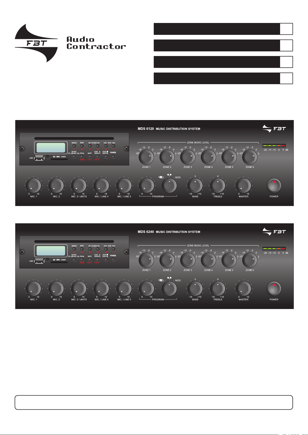
Sistema di diffusione sonora compatto
I
Compact sound-broadcasting system
Système de diffusion sonore compact
Kompaktes Beschallungssystem
UK
F
D
ISTRUZIONI PER L’USO
INSTRUCTIONS FOR USE
MDS 6120
MANUEL D’UTILISATION
MDS 6240
FBT ELETTRONICA S.p.A. - Via Paolo Soprani, 1 - ZONA IND. SQUARTABUE - 62019 RECANATI (MC) - ITALY
TEL. 071750591 r.a. - FAX 0717505920 - P.O. BOX 104 - E-mail: info@fbt.it - www.fbt.it
GEBRAUCHSANLEITUNG
Page 2

I
INDICE DEI CONTENUTI
UK
TABLE OF CONTENTS
1. AVVERTENZE 1
1.1 Alimentazione e messa a terra 1
1.2 Note di sicurezza 1
1.3 Installazione 1
2. DESCRIZIONE GENERALE
2.1 Pannello frontale 2
2.2 Pannello posteriore 3
3. DESCRIZIONE FUNZIONALITÀ
3.1 Gestione delle priorità 4
3.2 Ammutolimento degli ingressi 4
3.3 ‘Chime’ ed abilitazione VOX MIC.1 4
3.4 Chiamata zone 4
3.5 Tempo di rilascio VOX 4
4. CONNESSIONI
4.1 Criteri generali 5
4.2 Ingressi microfonici 5
4.3 Ingresso MIC.3/UNITS 5
4.4 Ingressi MIC/LINE 5
4.5 Filtro parola 6
4.6 Ingressi ausiliari 6
4.7 Ingresso telefonico 6
4.8 Uscita “MUSIC ON HOLD” 6
4.9 Collegamento delle postazioni 7
4.10 Collegamento ad un amplificatore esterno 8
4.11 Regolazione di volume della musica 9
4.12 Precedenza microfonica e Chime 9
4.13 Uscite di potenza 9
4.14 Uscita registratore e presa equalizzatore 9
5. IMPOSTAZIONI
6. USO 12
6.1 Messa in funzione 12
6.2 Controllo di volume principale 12
6.3 Correzione acustica 12
6.4 Modulo multifunzione 12
7. NOTE DI SERVIZIO
7.1 Sovraccarico e protezione 16
DATI TECNICI 17
5
10
16
2
4
1. WARNINGS 1
1.1 Power supply and earthing 1
1.2 Safety notes 1
1.3 Installation 1
2. GENERAL DESCRIPTION
2.1 Front panel 2
2.2 Rear panel 3
3. DESCRIPTION OF FUNCTIONS
3.1 Priority management 4
3.2 Muting of inputs 4
3.3 ‘Chime’ and enabling of the MIC.1 VOX function 4
3.4 Zone call 4
3.5 VOX release time 4
4. CONNECTIONS
4.1 General criteria 5
4.2 Microphone inputs 5
4.3 MIC.3/UNITS input 5
4.4 MIC/LINE inputs 5
4.5 Speech filter 6
4.6 Auxiliary inputs 6
4.7 Telephone input 6
4.8 “MUSIC ON HOLD” output 6
4.9 Connecting the stations 7
4.10 Connecting to an external amplifier 8
4.11 Music volume adjustment 9
4.12 Microphone precedence and Chime 9
4.13 Power outputs 9
4.14 Recorder output and equaliser socket 9
5. SETTINGS
6. USE 12
6.1 Start-up 12
6.2 Master volume control 12
6.3 Acoustic adjustment 12
6.4 Multi-purpose module 12
7. SERVICE NOTES
7.1 Overload and protection 16
TECHNICAL DATA 17
5
10
16
2
4
i
Page 3

F
SOMMAIRE
D
INHALTSANGABE
1. PRECAUTIONS 18
1.1 Alimentation et mise à la terre 18
1.2 Conseils de securite 18
1.3 Installation 18
2. DESCRIPTION GENERALE
2.1 Panneau frontal 19
2.2 Panneau posterieur 20
3. DESCRIPTION DES FONCTIONNALITÉS
3.1 Gestion des priorités 21
3.2 Assourdissement des entrées 21
3.3 Signal de préavis et d’activation VOX MIC.1 21
3.4 Appel des zones 21
3.5 Temps d’émission VOX 21
4. CONNEXIONS
4.1 Critères generaux 22
4.2 Entrées microphoniques 22
4.3 Entrée MIC.3/UNITS 22
4.4 Entrées MIC/LINE 22
4.5 Filtre voix 23
4.6 Entrées auxiliaires 23
4.7 Entrée téléphonique 23
4.8 Sortie “MUSIC ON HOLD” 23
4.9 Branchement des postes 24
4.10 Connexion à un amplificateur externe 25
4.11 Régler le volume de la musique 26
4.12 Priorité microphonique et signal de préavis 26
4.13 Sorties de puissance 26
4.14 Sortie enregistreur et prise egaliseur 26
5. REGLAGES
6. UTILISATION 29
6.1 Mise en marche 29
6.2 Contrôle de volume principal 29
6.3 Correction acoustique 29
6.4 Module multifonction 29
7. NOTICES DE SERVICE
7.1 Surcharge et protection 33
DONNEES TECHNIQUES 34
22
27
19
21
33
1. HINWEISE 18
1.1 Einspeisung und Erdung 18
1.2 Sicherheitsanweisungen 18
1.3 Installation 18
2. ALLGEMEINE BESCHREIBUNG
2.1 Frontpaneel 19
2.2 Rückpaneel 20
3. BESCHREIBUNG DER FUNKTIONEN
3.1 Steuerung der Vorrangschaltung 21
3.2 Stummschaltung der Eingänge 21
3.3
3.4 Zonenruf 21
3.5 Release-Zeit VOX 21
4. ANSCHLÜSSE
4.1 Allgemeine Hinweise 22
4.2 Mikrofoneingänge 22
4.3 Eingang MIC.3/UNITS 22
4.4 Eingänge MIC/LINE 22
4.5 Sprachfilter 23
4.6 Hilfseingänge 23
4.7 Telefoneingang 23
4.8 Ausgang “MUSIC ON HOLD” 23
4.9 Anschluss der Sprechstellen 24
4.10 Anschluss an einen externen Verstärker 25
4.11 Einstellen der Lautstärke der Musik 26
4.12 Mikrofonvorrang und Ankündigungssignal 26
4.13 Leistungausgänge 26
4.14 Ausgang Aufnahmegerät und Buchse Equalizer 26
5. EINSTELLUNGEN
6. GEBRAÜCH 29
6.1 Einschalten 29
6.2 Steuerung der Hauptlautstärke 29
6.3 Tonkorrektur 29
6.4 Multifunktions-Modul 29
7. SERVICEANWEISUNGEN
7.1 Überlastung und Schutz 33
TECHNISCHE EIGENSCHAFTEN
Ankündigungssignal und Freigabe von VOX MIC.1
22
27
19
21
21
33
34
ii
Page 4
I
AVVERTENZE WARNINGS
UK
1.1 ALIMENTAZIONE E MESSA A TERRA
Questi apparecchi sono predisposti per il funzionamento
con tensione di rete a 230 V ± 10% 50/60 Hz. È possibile
utilizzare l’apparecchio anche con una tensione di rete di
120 V ± 10% 50/60 Hz; a tal scopo è necessario portare il
selettore (
I sistemi compatti della Serie
alimentati con una sorgente esterna di corrente continua con
tensione di 24 V che deve essere applicata, rispettando le polarità,
ai relativi terminali della morsettiera (
di sicurezza, l’interruttore di accensione (7) agisce solo sulla
tensione di rete. In dotazione all’apparecchio é fornito un cavo di
alimentazione con filo di terra; il terminale di terra della spina di rete
non deve essere rimosso in alcun caso. Collegare la spina di rete
(11) dell’apparecchio alla rete elettrica utilizzando l’apposito cavo
fornito in dotazione; assicurarsi che la presa di corrente sia dotata
di collegamento di terra a norma di legge. L’apparecchio è protetto
da due fusibili (vedi Par. 7.1, pag. 16).
1.2 NOTE DI SICUREZZA
Durante il funzionamento dell’apparecchio è necessario assicurare
un’adeguata ventilazione. Evitare di racchiudere l’apparecchio in un
mobile privo di aerazione o di ostruire le fessure di ventilazione ed
in particolare la presa d’aria laterale della ventola di raffreddamento.
Evitare inoltre di tenere l’apparecchio in prossimità di sorgenti di
calore. Si consiglia di interporre un pannello di aerazione tra un
apparecchio e l’altro. Ogni intervento all’interno dell’apparecchio,
quale la selezione di alcuni modi d’uso o la sostituzione di fusibili,
deve essere effettuato solo da personale specializzato: la rimozione
del coperchio rende accessibili parti con rischio di scosse elettriche.
Prima di rimuovere il coperchio accertarsi sempre che il cavo
di rete sia staccato. Nel caso di accidentale caduta di liquidi
sull’apparecchio, staccare immediatamente la spina di rete ed
interpellare il centro di assistenza FBT più vicino. La connessione
di telaio (
sola funzione di schermatura dei segnali a basso livello: questa
presa non deve essere utilizzata per il collegamento di sicurezza
del telaio alla terra.
34) posto sul pannello posteriore in posizione “120 V”.
MDS 6000 possono anche essere
32). In accordo con le normative
12) consente di collegare altre apparecchiature per la
1.1 POWER SUPPLY AND EARTHING
This equipment is designed for use with a mains voltage of 230
V ± 10% 50/60 Hz. It is also possible to use the equipment with a
mains voltage of 120 V ± 10% 50/60 Hz; to do this it is necessary to
position the rear-panel selector switch (
systems of the MDS 6000 Series can also be powered by means
of an external DC power supply with a voltage of 24V, which has
to be applied to the appropriate terminals on the terminal strip (
paying attention to the correct polarity. As required under safety
regulations, the ON/OFF switch (
The equipment is supplied with its own power-supply cable, which
is equipped with an earthing wire. The earth terminal of the mains
plug should never be removed under any circumstances. Connect
the mains plug (11) of the equipment to the power mains using the
cable included in the supply. Make sure that the power outlet is
equipped with a connection to earth in accordance with the law.The
equipment is protected by two fuses (see point 7.1, page 16).
1.2 SAFETY NOTES
While the equipment is working, it is necessary to provide adequate
ventilation. Do not close the equipment in a cabinet without
ventilation. Do not obstruct the ventilation slits and particularly not
the lateral intake of the cooling fan. Do not keep the equipment in
the vicinity of sources of heat. It is recommended that you place
a ventilation panel between one piece of equipment and the next.
Any activities inside the equipment, such as selecting some of the
operating modes, the installation of accessories or the replacement
of fuses, must be carried out by specialized personnel only: when the
cover is removed, parts liable to cause electric shocks are exposed.
Before removing the cover, always make sure that the power cord
has been disconnected. In the event that liquid is accidentally spilt
onto the apparatus, disconnect the mains plug immediately and
contact the nearest FBT Service Centre. The chassis connection
(12) may be used to connect other equipment only for the purpose
of shielding the low signals: this socket may not be used to connect
the chassis to earth for safety purposes.
34) on “120 V”. The compact
32)
7) only controls the mains voltage.
1.3 INSTALLAZIONE
Questi apparecchi sono predisposti per il montaggio in mobile rack
standard 19” tramite l’uso di appositi accessori opzionali.
Avvertenze per lo smaltimento del prodotto ai sensi
della Direttiva Europea 2002/96/EC Alla fine della sua
vita utile il prodotto non deve essere smaltito insieme
ai rifiuti urbani, ma deve essere consegnato presso gli
appositi centri di raccolta differenziata predisposti dalle
amministrazioni comunali, oppure presso i rivenditori
che forniscono questo servizio. Smaltire separatamente un rifiuto
elettrico e/o elettronico (RAEE) consente di evitare possibili
conseguenze negative per l’ambiente e per la salute derivanti da
un suo smaltimento inadeguato e permette di recuperare i materiali
di cui è composto al fine di ottenere un importante risparmio di
energia e di risorse. Su ciascun prodotto è riportato a questo scopo
il marchio del contenitore di spazzatura barrato.
Questo prodotto è conforme alle Direttive della
Comunità Europea sotto le quali lo stesso ricade.
1.3 INSTALLATION
These equipments have provisions for mounting in a standard 19”
rack cabinet using optional accessories.
Important information for correct disposal of the
product in accordance with EC Directive 2002/96/EC
This product must not be disposed of as urban waste at
the end of its working life. It must be taken to a special
waste collection centre licensed by the local authorities
or to a dealer providing this service. Separate disposal
of electric and/or electronic equipment (WEEE) will avoid possible
negative consequences for the environment and for health resulting
from inappropriate disposal, and will enable the constituent materials
to be recovered, with significant savings in energy and resources.
As a reminder of the need to dispose of this equipment separately,
the product is marked with a crossed-out wheeled dustbin.
This product is in keeping with the
relevant European Community Directives.
1
Page 5
I
DESCRIZIONE GENERALE GENERAL DESCRIPTION
UK
I sistemi compatti
interna in grado di gestire selezioni, funzioni Chime/VOX e postazioni
microfoniche.
MDS 6120 e MDS 6240 sono dotati di una CPU
MDS 6120 and MDS 6240 compact systems have an internal CPU
capable of managing the selections, the Chime/VOX functions and
microphone stations.
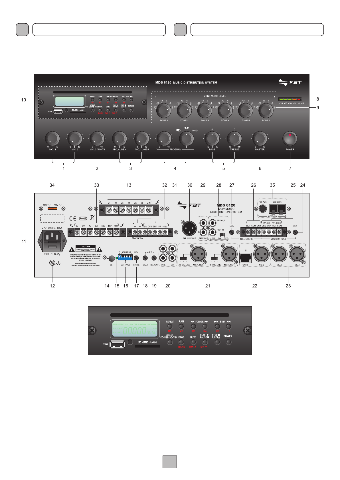
2.1 PANNELLO FRONTALE
1. Controlli di livello ingressi microfonici.
2. Controllo di livello ingresso microfonico/unità.
3. Controlli di livello ingressi microfonici/linea.
4. Controllo di livello e selezione ingressi ausiliari.
5. Controlli di tono.
6. Controllo di volume generale.
7. Interruttore di rete.
8. Visualizzatore del livello d’uscita.
9. Regolazioni di livello del segnale musicale (zone 1÷6).
10. Modulo multifunzione.
2.1 FRONT PANEL
1. Level control for microphone inputs.
2. Microphone input/unit level control.
3. Microphone input/line level control.
4. Level control and selection of auxiliary inputs.
5. Tone controls.
6. General volume control.
7. Mains switch.
8. Output level indicator.
9. Music signal level adjustment (zone 1 to 6).
10. Multi-purpose module.
2
Page 6

I
DESCRIZIONE GENERALE GENERAL DESCRIPTION
UK
2.2 PANNELLO POSTERIORE
11. Spina di rete con fusibile incorporato.
12. Connessione telaio.
13. Morsettiera selezione zone.
14. Pulsante impostazioni.
15. Led conferma acquisizione impostazioni.
16. Dip-switches impostazioni.
17. Regolazione di livello del segnale di preavviso.
18. Regolazione soglia d’attivazione precedenza ingresso MIC.1.
19. Regolazione soglia d’attivazione precedenza ingresso
TEL./EMERG.
20. Ingressi ausiliari.
21. Ingressi MIC/LINE 4-5 e relativi selettori
di modalità funzionamento.
22. Ingresso MIC.3/Unità MBT 1106.
23. Ingressi microfonici.
24. Regolazione di livelllo uscita MUSIC ON HOLD.
25. Uscite di linea e di potenza MUSIC ON HOLD.
26. Ingresso emergenza da centralino telefonico.
27. Regolazione di livello ingresso telefonico.
28. Prese per equalizzatore esterno.
29. Uscita per registratore.
30. Uscita di linea bilanciata.
31. Connessioni precedenza e override.
32. Morsettiera per alimentazione esterna in corrente continua.
33. Morsettiera uscita altoparlanti.
34. Selettore della tensione di rete.
35. Prese per antenne FM ed AM.
2.2 REAR PANEL
11. Mains plug with built-in fuse.
12. Frame connection.
13. Zone selection terminal strip.
14. Push-button for settings.
15. LED for confirming acquisition of settings.
16. DIP switches for making settings.
17. Level control of the warning signal.
18. MIC.1 input precedence activation threshold adjustment.
19. TEL./EMERG. input precedence activation
threshold adjustment.
20. Auxiliary inputs.
21. MIC/LINE inputs 4-5 and relevant
operating mode selector switches.
22. MIC.3 input / MBT 1106 unit.
23. Microphone inputs.
24. MUSIC ON HOLD output level adjustment.
25. MUSIC ON HOLD line and power outputs.
26. Emergency input from PABX.
27. Telephone input level adjustment.
28. Sockets for external equaliser.
29. Output for recorder.
30. Balanced line output.
31. Precedence and override connections.
32. Terminal strip for external DC power supply.
33. Loudspeakers output terminal strip.
34. Mains voltage selector switch.
35. Sockets for FM and AM aerials.
3
Page 7

I
DESCRIZIONE FUNZIONALITÀ DESCRIPTION OF FUNCTIONS
UK
La caratteristica principale di questi apparecchi è la possibilità di
selezionare nel dettaglio la modalità operativa dell’apparecchio
tramite dip-switches, che consentono di verificare e/o modificare le
impostazioni di tutti i parametri di funzionamento. Nello specifico, è
possibile impostare quanto riportato nei paragrafi successivi.
3.1 GESTIONE DELLE PRIORITÀ
Le postazioni microfoniche MBT 11
TEL./EMERG.
ed è possibile attribuirvi un ulteriore livello prioritario (HIGH/LOW).
In caso di pari priorità selezionate, il primo in ordine di tempo ad
aver effettuato la chiamata mantiene la parola. Inoltre, è possibile
gestire le priorità del contatto di precedenza e del VOX dell’ingress
MIC.1.
Impostazione di fabbrica
• Ingresso telefonico = priorità alta (HIGH)
• Ingresso postazione = priorità bassa (LOW)
• Contatto di precedenza = priorità alta (HIGH)
• VOX MIC.1 = priorità bassa (LOW)
3.2 AMMUTOLIMENTO DEGLI INGRESSI
La chiusura del contatto di precedenza e l’intervento del VOX
dell’ingresso MIC.1 ammutoliscono sempre il segnale musicale e
gli ingressi microfonici selezionati nelle impostazioni.
Impostazione di fabbrica
• Contatto di precedenza = ammutolisce ingressi microfonici 3÷5.
• VOX MIC.1 = ammutolisce ingressi microfonici 2÷5.
hanno priorità su qualsiasi altra sorgente di chiamata
06 ed il VOX dell’ingresso
The main feature of these pieces of equipment is the possibility of
making a detailed choice of operating mode of the equipment by
means of DIP switches that enable the settings of all the operating
parameters to be checked and/or changed. Specifically, it is possible
to set the functions illustrated in the following sections.
3.1 PRIORITY MANAGEMENT
MBT 11
TEL./EMERG. input have priority over any other source of calls,
and it is possible to attribute a further level of priority (HIGH/LOW)
to each of them. In the event that inputs having the same level of
priority are selected, the first in order of time that made the call will
o
retain priority. It is also possible to manage priority of the precedence
contact and of VOX contact of the MIC.1 input.
Factory settings
• Telephone input = high priority (HIGH)
• Station input = low priority (LOW)
• Precedence contact = high priority (HIGH)
• VOX MIC.1 = low priority (LOW)
3.2 MUTING OF INPUTS
Closure of the precedence contact and activation of the VOX contact
of the MIC.1 input always mute the music signal and the microphone
inputs selected when making the settings.
Factory settings
• Precedence contact = mutes microphone inputs 3 to 5.
• VOX MIC.1 = mutes microphone inputs 2 to 5.
06
microphone stations and the VOX function of the
3.3 ‘CHIME’ ED ABILITAZIONE VOX MIC.1
È possibile attivare/disattivare l’invio di un segnale di preavviso
(Chime) come conseguenza della chiusura del contatto di
precedenza e/o della chiamata proveniente da una postazione
microfonica MBT 1106; è inoltre possibile abilitare/disabilitare la
funzione VOX dell’ingresso MIC.1: se disabilitata, questo ingresso
si comporta come un normale ingresso microfonico.
Impostazione di fabbrica
• Ingresso postazione = Chime attivato
• Contatto di precedenza = Chime attivato
• VOX MIC.1 = VOX abilitato
• Amplificatore esterno = disattivato
3.4 CHIAMATA ZONE
Le postazioni MBT 1106 consentono, direttamente tramite tastiera, di
inviare chiamata ad una o più zone d’ascolto. Le chiamate effettuate
dal VOX dell’ingresso MIC.1, dal VOX dell’ingresso TEL./EMERG.
e dalla chiusura del contatto di precedenza selezionano una o più
delle zone d’ascolto in dipendenza dalle impostazioni effettuate.
Ogni sorgente di chiamata ha una propria configurazione di zona.
Impostazione di fabbrica
• Ch
iamata da VOX dell’ingresso TEL./EMERG. = chiamata generale
• Chiamata da VOX dell’ingresso MIC.1 = chiamata generale
• Chiamata da contatto di precedenza = chiamata generale
3.3 ‘CHIME’ AND ENABLING OF THE MIC.1 VOX FUNCTION
It is possible to acti
(chime) as a consequence of closing of the precedence contact
and/or of the call coming from a MBT 1106 microphone station.
It is also possible to enable/disable the VOX function of the
MIC.1 input. If this input is disabled, it behaves like an ordinary
microphon
Factory settings
• Station input = Chime activated
• Precedence contact = Chime activated
• MIC.1 VOX = VOX enabled
• External amplifier = disabled
3.4 ZONE CALL
The MBT 1106 stations enable calls to be sent to one or more
listening zones, using the keyboard. Calls made from the VOX of
the MIC.1 input, from the VOX of the TEL./EMERG. input and by
closing the precedence contact select one or more of the listening
zones, depending on the settings that have been made. Each call
source has its own zone configuration.
Factory setting
• Call from VOX of the TEL./EMERG. input = All Call
• Call from VOX of the MIC.1 input = All Call
• Call from precedence contact = All Call
e input.
vate/de-activate sending of a warning signal
3.5 TEMPO DI RILASCIO VOX
L’at
tivazione della funzione VOX dell’ingresso MIC.1 e dell’ingresso
TEL./EMERG.
è impostabile ed è possibile prolungarlo fino ad un massimo di ~
6 sec.
Impostazione di fabbrica
• Tempo rilascio VOX = base + 2 sec
Per la verifica, la modifica dei parametri e/o il dettaglio delle
impostazioni, fare riferimento al Cap. 5 “Impostazioni”, pag. 10.
è pressochè immediata, mentre il tempo di rilascio
3.5 VOX RELEASE TIME
Activation of the VOX function of the
EMERG. input takes place almost immediately, while the release
time can be set, extending it up to a maximum of ~ 6 seconds.
Factory setting
• VOX release time = base + 2 secs.
To check or alter the parameters and/or the details of the settings,
see Chapter 5 “Settings” on page 10.
MIC.1
input and of the TEL./
4
Page 8

I
CONNESSIONI CONNECTIONS
UK
4.1 CRITERI GENERALI
Per un corretto funzionamento dell’apparecchio è opportuno osservare
alcuni criteri di massima nell’esecuzione dei collegamenti:
n posizionare cavi e microfoni sul mobile dell’apparecchio.
• no
• evitare di stendere le linee di segnale parallele a quelle di rete;
osservare una distanza minima di 30/40 cm.
• posizionare le linee di ingresso e le linee di uscita distanti tra loro.
• posizionare i microfoni al di fuori dell’angolo di radiazione dei
diffusori sonori per evitare il fenomeno di reazione acustica (effetto
Larsen).
4.2 INGRESSI MICROFONICI
Alle prese XLR
MIC.1 e MIC.2 (23) è possibile collegare microfoni
di tipo dinamico e ad elettrete con alimentazione Phantom; i
collegamenti a queste prese sono riportati nella Fig. 4.2.1. Ulteriori
possibilità di connessione, che sfruttano l’uso della morsettiera (31),
sono riportate al Par. 4.12, pag. 9.
Collegamento BILANCIATO
1 Schermo
2 Segnale (lato caldo)
3 Segnale (lato freddo)
Collegamento SBILANCIATO
1 Schermo e massa
2 Segnale
3 Schermo e massa
4.1 GENERAL CRITERIA
For proper unit operation, use the following instructions when making
the connections:
• Do not place cables or microphones on the unit cabinet;
• Do not lay signal lines parallel to power lines; ensure a minimum
distance of 30/40 cm between them;
• Keep input lines and the output lines far apart;
• Keep the microphones outside the operating span of the speakers
to avoid acoustic feedback (Larsen effect).
4.2 MICROPHONE INPUTS
It is possible to connect microphones of the dynamic or of the electret
type with a Phantom power supply to the XLR sockets
MIC.1 and
MIC.2 (23). The connections to these sockets are shown in Figure
4.2.1. Further possible connections exploiting the terminal strip (31)
are indicated under point 4.12, page 9.
BALANCED connection
12
3
1 Shield
2 Signal (hot side)
3 Signal (cold side)
UNBALANCED connection
1 Shield and GND
2 Si gnal
3 Shield and GND
Ogni ingresso microfonico dispone di un proprio controllo di livello (1)
per dosare opportunamente l’ampiezza dei vari segnali.
L’ingresso
microfonico MIC.1 dispone, inoltre, della funzione di precedenza
automatica (VOX): parlando al microfono collegato a questo
ingresso verranno automaticamente ammutoliti tutti gli ingressi
musicali e quelli microfonici secondo le impostazioni memorizzate.
Il livello della soglia d’attivazione del circuito di precedenza
automatica è indipendente dalla posizione del controllo MIC.1 (1).
Negli ingressi microfonici MIC.1 e MIC.2 l’alimentazione Phantom è
fissa. La funzione VOX può essere disattivata portando in posizione
di fine corsa in senso ORARIO il trimmer A.P.T. MIC.1 (
18).
Portando il trimmer in posizione di fine corsa in senso
ANTIORARIO,
verranno ammutoliti in modo permanente
tutti gli ingressi tranne quello telefonico.
4.3 INGRESSO MIC.3/UNITS
Alla presa XLR
MIC.3 (22) è possibile collegare microfoni di tipo
dinamico e ad elettrete con alimentazione Phantom; i collegamenti
a queste prese sono riportati nella Fig. 4.2.1. In alternativa al
microfono, è possibile collegare alla presa IN UNITS una o più
postazioni microfoniche preamplificate
MBT 1106, che consentono di
inviare messaggi su una o più zone d’ascolto. Per il collegamento
di questa postazione, è INDISPENSABILE utilizzare cavi
schermati di tipo STP CAT5.E. La regolazione del livello d’uscita
è disponibile al controllo frontale (
2).
Fig. 4.2.1
Each microphone input has its own level control (
amplitude of the various signals suitably.
1) for adjusting the
The MIC.1 microphone
input also has an automatic precedence function (VOX). When
speaking into the microphone connected to this input, all the music
inputs and microphone inputs will be muted on the basis of the stored
settings. The level of the threshold for activation of the automatic
precedence circuit is independent of the position of the MIC.1 control
(1). The phantom power supply in microphone inputs MIC.1 and
MIC.2 is fixed. The VOX function can be de-activated by turning
the MIC.1 A.P.T. trimmer (
18) in a CLOCKWISE direction until it
reaches the end-of-travel position.
If the trimmer is turned in an ANTICLOCKWISE direction as
far as it will go,
all the inputs except the telephone input
will be permanently muted.
4.3 MIC.3/UNITS INPUT
It is possible to connect a dynamic or electret microphone with
a Phantom power supply to the MIC.3 XLR socket (22). The
connections to these sockets are shown in Fig. 4.2.1. As an
alternative to a microphone, it is also possible to connect one or more
MBT 1106 pre-amplified microphone stations, enabling messages
to be sent to one or more listening zones, to the IN UNITS socket.
It is ESSENTIAL to use shielded cables of the STP CAT5.E type
for connecting this station. The output level can be controlled
from the front panel (2).
4.4 INGRESSI MIC/LINE
Le prese
MIC/LINE 4 e MIC/LINE 5 (21) sono configurabili in modo
indipendente come ingressi microfonici (con o senza alimentazione
Phantom) o come ingressi di linea.
4.4 MIC/LINE INPUTS
MIC/LINE 4 and MIC/LINE 5 sockets (21) can be separately
The
configured as microphone inputs (with or without phantom power
supply) or as line inputs.
5
Page 9
I
CONNESSIONI CONNECTIONS
UK
La selezione della modalità è ottenuta tramite i relativi deviatori a
tre posizioni posti a lato delle prese:
• in posizione
alimentazione phantom disattivata;
• in posizione PH, si seleziona la sensibilità microfonica attivando
l’alimentazione phantom (per microfoni elettrete 12/24V);
• in posizione
I collegamenti a queste prese sono riportati nella Fig. 4.2.1. Ogni
ingresso dispone di un proprio controllo di livello (
opportunamente l’ampiezza dei vari segnali.
4.5 FILTRO PAROLA
Agli ingressi MIC.1-2-3, MIC/LINE 4-5 è possibile inserire un filtro
parola. Per effettuare queste modifiche è necessario togliere il
coperchio dell’apparecchio:
ESCLUSIVAMENTE da personale specializzato. L’impostazione di
fabbrica prevede che il filtro sia disinserito: per inserirlo, posizionare
il jumper relativo all’ingresso/i interessato/i in posizione
seguendo la tabella sottostante:
MIC, si seleziona la sensibilità microfonica con
LINE, si seleziona la sensibilità di linea.
3) per dosare
questa operazione deve essere svolta
ON,
Jumper Ingresso
JP301 MIC.1
JP302 MIC.2
JP303 MIC.3/UNITS
JP304 MIC./LINE 4
JP305 MIC./LINE 5
The operating mode can be selected by means of the specific threeposition switches next to the sockets:
• in the
• in the PH position the sensitivity of the microphone with
• in the
The connections to these sockets are shown in Figure 4.2.1. Each
input has its own level control (
amplitude of the various different signals suitably.
4.5 SPEECH FILTER
It is possible to install a speech filter on inputs MIC.1-2-3 and
LINE 4-5
be removed. This operation must be carried out by specialised
personnel ONLY. According to the factory setting, the filter is
de-activated. To activate it, place the jumper referred to the input
in question in the ON position, in accordance with the following
table:
MIC position the sensitivity of the microphone with the
phantom power supply de-activated is selected;
the phantom power supply activated (for 12/24V electret
microphones) is selected;
LINE position the sensitivity of the line is selected.
3) so as to be able to adjust the
MIC/
. To make these changes, the lid of the equipment must
Jumper Input
JP301 MIC.1
JP302 MIC.2
JP303 MIC.3/UNITS
JP304 MIC./LINE 4
JP305 MIC./LINE 5
4.6 INGRESSI AUSILIARI
Alle prese phono TAPE e CD (20) è possibile collegare 2 sorgenti
musicali ad alto livello (lettore di compact disc, riproduttore a nastro).
La doppia presa consente un veloce collegamento della sorgente
all’amplificatore tramite cavetto stereo: la miscelazione dei due
canali destro e sinistro (L/R) è realizzata internamente. La selezione
e la regolazione di livello della sorgente avviene tramite l’apposito
controllo PROGRAM (4) posto sul pannello frontale dell’apparecchio.
La sorgente selezionata è soggetta all’ammutolimento sia per
precedenza automatica (VOX) degli ingressi
MIC.1 che per la chiusura del contatto PR (precedenza) o in caso
di chiamata proveniente da postazioni microfoniche MBT 1106.
4.7 INGRESSO TELEFONICO
L’apparecchio è predisposto per il collegamento ad un sistema
telefonico tramite la morsettiera
è bilanciato a trasformatore, possiede un proprio controllo di livello LEV. (27) - ed è dotato di circuito VOX per la diffusione dei messaggi
con priorità più elevata rispetto a qualsiasi altro ingresso, eccetto le
postazioni MBT 1106 conformemente alle impostazioni di priorità
selezionate.
4.8 USCITA “MUSIC ON HOLD”
A questi morsetti (
selezionata sugli ingressi ausiliari (20); tale segnale non è soggetto
all’azione di precedenza microfonica o telefonica. In particolare,
l’uscita bilanciata a trasformatore (morsetti COM-HOT di fig. 4.8.1)
può essere utilizzata per il pilotaggio di un ulteriore amplificatore,
di un centralino telefonico od altro.
25) è disponibile il segnale della sola sorgente
TEL./EMERG. (26). Tale ingresso
TEL./EMERG. e
4.6 AUXILIARY INPUTS
It is possible to connect two high-level sources of music (CD player,
tape recorder) to the TAPE and CD (20) phono sockets. Thanks to
the fact that there are two sockets, it is easy to connect the source
rapidly to the amplifier by means of a stereo cable: mixing of the two
channels (left and right - L/R) is carried out internally. The source is
selected by means of the selector PROGRAM (4)provided for this
purpose on the front panel of the equipment. The source selected
is subject to muting both due to automatic precedence (VOX) of
TEL./EMERG. and MIC.1 inputs and following closure of the
the
PR (precedence) contact, or in case of a call from a MBT 1106
microphone station.
4.7 TELEPHONE INPUT
The equipment has provisions for connection to a telephone system
via the
TEL./EMERG. terminal strip (26). This input is balanced by a
transformer, has its own level control - LEV. (27) – and is equipped
with a VOX circuit for broadcasting messages with a higher priority
than any other input except for the MBT 1106 stations, in accordance
with the priority settings that have been selected.
4.8 “MUSIC ON HOLD” OUTPUT
The signal of the only source selected on the auxiliary inputs (
is available on these terminals (25). This signal is not affected
by the use of telephone precedence. In particular, the balanced
transformer output (strips COM-HOT, Fig. 4.8.1) can be used to drive
an additional amplifier, a telephone exchange or other equipment.
20)
6
Page 10
I
CONNESSIONI CONNECTIONS
UK
L’uscita di potenza (morsetti MON-GND) è in grado di pilotare
direttamente un piccolo altoparlante monitor da 8 ohm con potenza
massima di 1 W. É possibile regolare il livello di uscita agendo sul
controllo LEV. (24).
TEL./EMERG.
ingresso (lato caldo)
HOT
input (warm side)
ingresso (lato freddo)
COM
input (cold side)
massa e schermo
GND
GND and shield
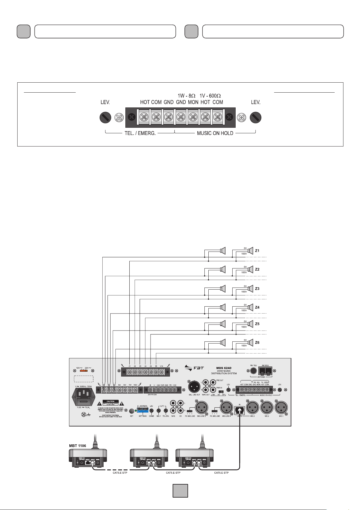
4.9 COLLEGAMENTO DELLE POSTAZIONI
I sistemi compatti della Serie
MDS 6000 possono essere collegati
in modo semplice e veloce le postazioni microfoniche MBT 1106.
Queste postazioni microfoniche preamplificate sono caratterizzate
entrambe da un microfono elettrete e consentono di inviare
messaggi su una o più zone d’ascolto. Per il collegamento di questi
due modelli, è INDISPENSABILE utilizzare dei cavi STP CAT5.E
(schermati). La selezione zone verrà automaticamente effettuata
tramite la connessione alla presa IN UNITS (22): nella figura
4.9.1 viene illustrato l’esempio di collegamento per un impianto di
chiamata a sei zone. La regolazione del livello d’uscita è disponibile
tramite controllo frontale (2).
The power output (terminals MON-GND in Figure 4.7.1) is capable
of driving directly a small 8 ohm monitoring loudspeaker with a
maximum output of 1 W. It is possible to adjust the output level by
means of the LEV. control (24).
MOH
1W/8W
MON
GND
1V/600W
HOT
COM
uscita altoparlante
loudspeaker output
massa altoparlante
loudspeaker GND
uscita (lato caldo)
output (warm side)
massa e schermo
GND and shield
Fig. 4.8.1
4.9 CONNECTING THE STATIONS
Connecting the
MBT 1106 microphone stations to MDS 6000
compact systems is simple and rapidly achieved.
Both these pre-amplified microphone stations feature electret
microphones, and enable messages to be sent to one or more
listening zones.
To connect these two models, it is ESSENTIAL
to use STP CAT 5.E cables (shielded).
The selection will be made automatically via connection to the
IN
UNITS socket (22). An example of a connection for a six-zone calling
system is illustrated in Figure 4.9.1. The output level is controlled
from the front panel (2).
Fig. 4.9.1
7
Page 11
I
CONNESSIONI CONNECTIONS
UK
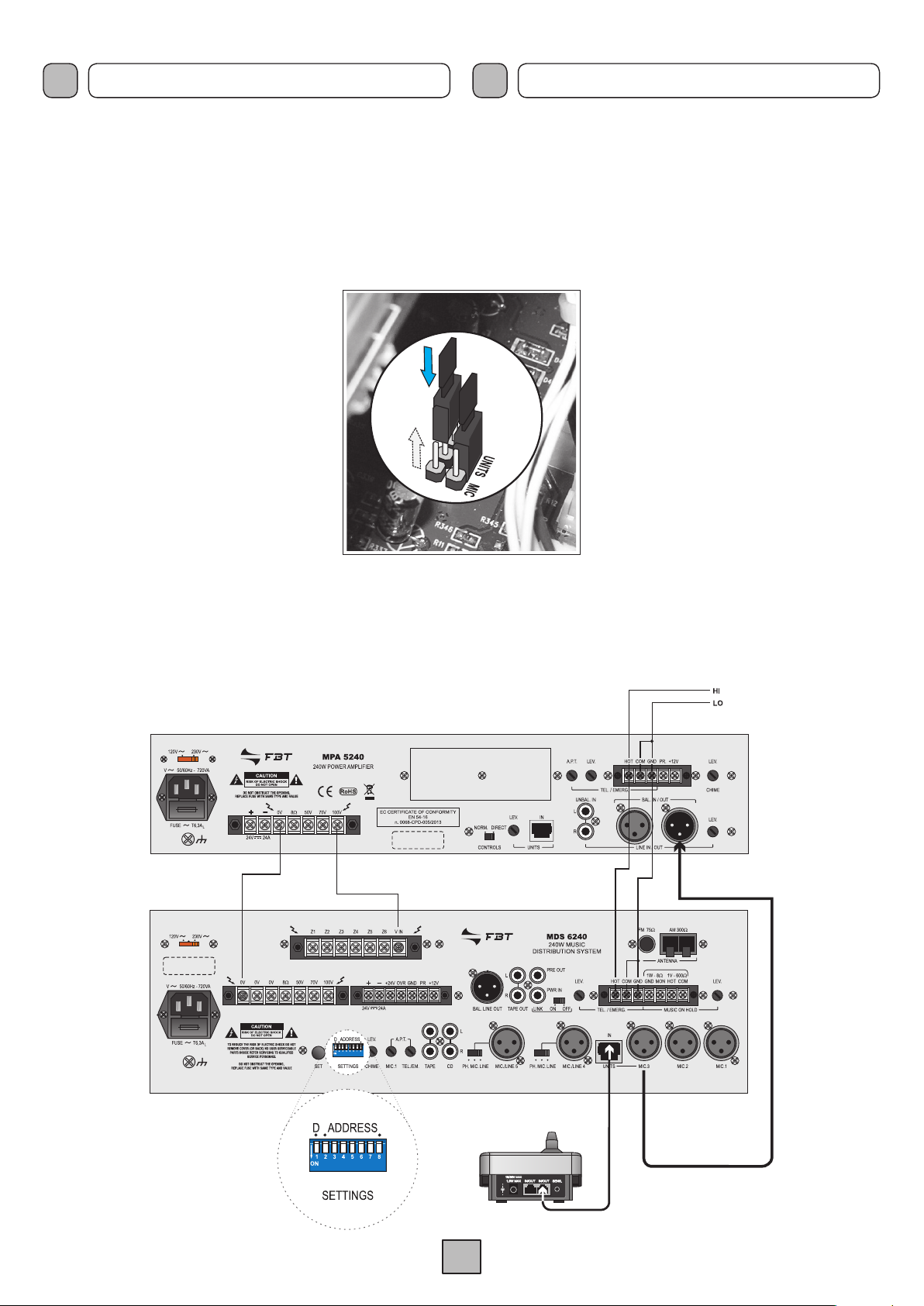
4.10 COLLEGAMENTO AD UN AMPLIFICATORE ESTERNO
Colle g a n d o un am p lificatore es t e rno è po s sibile aver e
simultaneamente annunci e musica di sottofondo in zone diverse.
Per sfruttare questa opzione, seguire le indicazioni sottostanti.
ATTENZIONE! Questa operazione deve essere effettuata SOLO
da personale specializzato: la rimozione del coperchio rende
accessibili parti con rischio di scosse elettriche. Prima di rimuovere
il coperchio accertarsi sempre che il cavo di rete sia staccato.
1) Rimuovere il coperchio dell’apparecchio
svitando le viti presenti sulle fiancate.
2) Individuare i due jumper evidenziati in
figura 4.10.1 e spostarli dalla posizione
MIC. (impostazione di fabbrica) alla
posizione UNITS: questo consentirà al
segnale audio proveniente dalle postazioni
microfoniche collegate alla presa
UNITS (22) di venire dirottato in uscita alla
MIC.3.
presa
3) Collegare il morsetto
esterno ad uno dei morsetti 0V disponibili
sulla morsettiera (33) dell’apparecchio.
4) Collegare il morsetto
esterno al morsetto V IN della morsettiera
(13).
5) Collegare tramite cavo bilanciato la presa XLR MIC.3 (22) con
la spina XLR dell’amplificatore esterno.
6) Abilitare tramite i dip-switches (
con amplificatore esterno (vedere pag. 11).
0V dell’amplificatore
100V dell’amplificatore
16) la modalità di funzionamento
IN
4.10 CONNECTING TO AN EXTERNAL AMPLIFIER
By connecting an external amplifier, it’s possible to have
announcements and background music simultaneously in different
areas. To exploit this option, follow the directions below.
WARNING! This operation must be performed ONLY by specialists:
the removal of the lid makes accessible parts with risk of electric
shock. Before removing the cover make sure that the network
cable is disconnected.
1) Remove the cover by unscrewing the
screws on the sides of the equipment.
2) Locate the two jumpers illustrated in Figure
4.10.1 and move them out of
(factory default) to
allow the audio signal coming from the
microphone stations connected to the
UNITS (22) socket to be diverted to output
socket MIC.3.
3) Connect the
an external terminal 0V available on the
terminal strip (33) of the equipment.
4) Connect the external amplifier
terminal to V IN of the terminal strip (13).
Fig. 4.10.1
5) Connect the
the XLR plug external amplifier.
6) Enable via the dip-switches (
external amplifier (see page 11).
MIC.3 socket (22) with a balanced XLR cable with
UNITS position: this will
0V terminal of the amplifier to
16) the operation mode with
MIC position
IN
100V
Fig. 4.10.2
8
Page 12
I
CONNESSIONI CONNECTIONS
UK
4.11 REGOLAZIONE DI VOLUME DELLA MUSICA
Il volume della musica di sottofondo diffusa in ogni singola zona può
essere regolato tramite gli appositi controlli ‘ZONE MUSIC LEVEL’
(9) presenti sul pannello frontale degli apparecchi.
4.12 PRECEDENZA MICROFONICA E CHIME
Chiudendo i contatti PR e +12V della morsettiera (31) vengono
ammutoliti tutti gli ingressi tranne MIC.1 e TEL./EMERG. La chiusura
del contatto genera un segnale di preavviso a due toni (CHIME): è
possibile modificare il livello del segnale di preavviso agendo sul
relativo trimmer LEV. (17).
NOTA
: Il segnale di preavviso può essere disattivato seguendo la
procedura indicata nel cap. 5 “Impostazioni”, pag. 10.
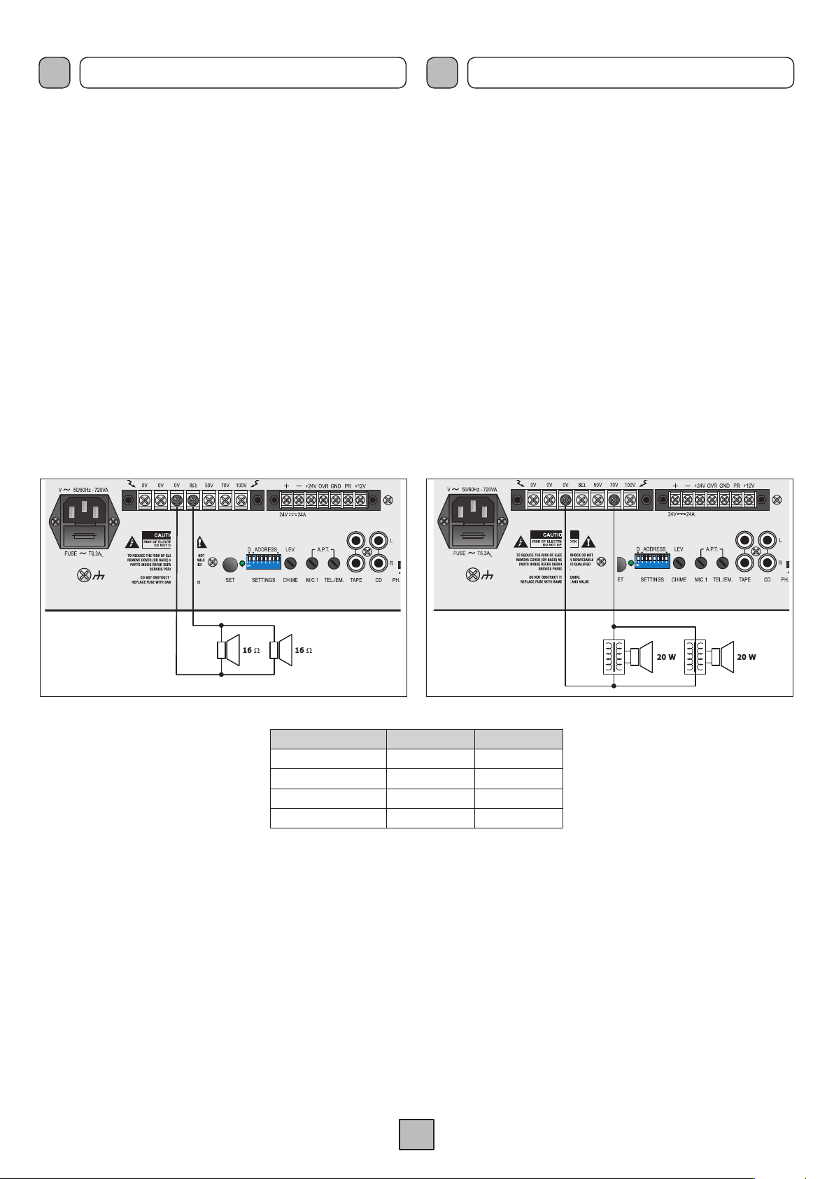
4.13 USCITE DI POTENZA
Le uscite di potenza per i diffusori sono disponibili sulla morsettiera
(33). È possibile realizzare un impianto di diffusione sonora
utilizzando sia diffusori a bassa impedenza (fig. 4.13.1), sia diffusori
dotati di traslatore di linea (fig. 4.13.2). In entrambi i casi il carico
complessivo non deve essere tale da sovraccaricare l’amplificatore:
non applicare cioè diffusori o gruppi di diffusori con impedenza più
bassa di quella nominale della presa alla quale sono collegati.
4.11 MUSIC VOLUME ADJUSTMENT
The volume of the background music spread to every single zone
can be adjusted through the appropriate controls ‘
LEVEL’ (9) on the front panel of the equipment.
4.12 MICROPHONE PRECEDENCE AND CHIME
When the contacts PR and
all the inputs are muted except for MIC.1 and TEL./EMERG. Closing
of the contact generates a two-tone warning signal (CHIME). It is
possible to adjust the level of the warning signal by means of the
LEV. trimmer (17).
NOTE:
The warning signal can be deactivated following the procedure
indicated in Chapter 5 “Settings” on page 10.
4.13 POWER OUTPUTS
The power outputs for the loudspeakers are available on the terminal
strip (
33). It is possible to set up a sound-broadcasting system using
either low-impedance loudspeakers (fig. 4.13.1) or loudspeakers
equipped with a line transformer (fig. 4.13.2). In both cases the overall
load must not be such as to overload the amplifier. This means that
you must not apply loudspeakers or groups of loudspeakers with an
impedance lower than the rated impedance of the socket to which
they are connected.
+12V of the terminal strip (31) are closed,
ZONE MUSIC
Si raccomanda inoltre di porre particolare
attenzione al calcolo delle impedenze
nel caso si debbano realizzare impianti
di diffusione misti (a bassa impedenza e
a tensione costante). In tab. 4.13.3 sono
riportati i valori nominali di tensione ed
impedenza per le diverse uscite.
4.14 USCITA REGISTRATORE E PRESA EQUALIZZATORE
Nei casi in cui fosse richiesta una elaborazione acustica del segnale,
è possibile collegare un equalizzatore, od altro elaboratore di segnale,
alle prese PWR IN e PRE OUT (28) dell’apparecchio. Per l’inserzione
dell’equalizzatore, l’interruttore LINK posto sul retro dell’apparecchio
deve essere nella posizione OFF. Questa realizzazione permette
la correzione acustica di ambienti particolarmente riverberanti e la
soppressione della retroazione acustica diffusore-microfono (effetto
Larsen). Se all’amplificatore non sono collegate, tramite le prese
PWR IN e PRE OUT, apparecchiature esterne, l’interruttore LINK
deve essere posto in posizione ON per mantenere la continuità
della catena amplificatrice. Alla presa di uscita TAPE OUT (29) è
disponibile il segnale di pilotaggio della parte di potenza costituito
dalla miscelazione delle diverse sorgenti prima del controllo di
volume generale MASTER (6). Tale segnale può essere utilizzato
per il pilotaggio di unità di potenza e/o inviato ad una piastra di
registrazione.
Uscita • Output MDS 6120 MDS 6240
8
W
50 V
70 V
100 V
Fig. 4.13.2Fig. 4.13.1
It is also necessary to pay particular
31 V 43,8 V
20,8
W 10,4 W
40,8
W 20,4 W
83,3
W 41,7 W
Tab. 4.13.3
4.14 RECORDER OUTPUT AND EQUALISER SOCKET
In those cases in which acoustic processing of the signal is required,
it is possible to connect an equaliser or other signal processing
equipment to the PWR IN and PRE OUT sockets (
equipment. When inserting the equaliser, the LINK switch on the
rear of the equipment must be in the OFF position. This application
enables acoustic correction of rooms subject to particularly severe
reverberation and the suppression of acoustic feedback between
loudspeakers and microphones (Larsen effect). If no external
equipment is connected to the amplifier by means of the PWR
IN and PRE OUT sockets, the LINK switch must be in the ON
position in order to maintain continuity of the amplifier chain.
The signal driving the power part consisting of the signal resulting
from the mixing of the various sources before the
control (6) is available on the TAPE OUT output socket (29). This
signal can be used to drive power units and/or sent to a recording
deck.
attention to calculating the impedance
values if mixed broadcasting systems
(low impedance and constant voltage)
are to be set up. Table 4.13.3 shows
voltage and impedance rated values for
the various outputs.
28) on the
MASTER volume
9
Page 13

I
IMPOSTAZIONI SETTINGS
UK
Sul pannello posteriore sono disponibili i controlli SETTINGS (16)
(dip-switches, led e pulsante
e/o modificare le impostazioni di funzionamento. Ogni parametro è
contraddistinto da un indirizzo e dal suo valore (ON/HIGH o OFF/
LOW). L’indirizzo è selezionato sui dip-switches ADDRESS (2÷8),
dove 8 è il bit più significativo (MSB) e 2 è il bit meno significativo
(LSB). Il valore (o dato) è selezionato dal dip-switch D (1).
La procedura per la verifica del parametro impostato è la
seguente:
1) selezionare l’indirizzo tramite i dip-switches ‘ADDRESS’
(da 2 a 8);
2) Premere brevemente il pulsante SET;
3) Se il led lampeggia brevemente, il parametro selezionato è
OFF o con livello di priorità basso (LOW); se il led lampeggia
per almeno 2 sec., il parametro selezionato è ON o con livello
di priorità alto (HIGH).
NOTA:
La lettura è indipendente dalla posizione del dip-switch ‘D’ (1).
La procedura per la modifica del parametro impostato è la
seguente:
1) selezionare l’indirizzo tramite i dip-switches ‘ADDRESS’
(da 2 a 8);
2) selezionare tramite il dip-switch ‘D’ (1) il valore del parametro
(ON = HIGH) o (OFF = LOW);
3) premere per più di 2 secondi il pulsante SET;
4) il led lampeggia 2 volte ad indicare che la modifica è stata
acquisita dall’amplificatore ed è immediatamente attiva (non è
necessario effettuare altre operazioni).
SET) che consentono di verificare
SETTINGS controls (16) are on the rear panel (DIP switches,
The
LEDs and a SET push-button). These can be used to check and/or
change the operational settings. Each parameter is characterised
by an address and a value (ON/HIGH or OFF/LOW). The address is
selected by means of the ADDRESS DIP switches (2 to 8), where 8
is the most significant bit (MSB) and 2 the least significant bit (LSB).
The value (or datum) is selected by means of DIP switch D (1).
The procedure for checking the parameter that has been set is
as follows:
1) Use the ‘ADDRESS’ dip switches (2 to 8) to select the
address;
2) Press the SET push-button briefly;
3) If the LED flashes briefly, the parameter that has been selected
is OFF, or with a LOW priority level. If the LED lights up for at
least 2 seconds, the parameter that has been selected is ON,
or with a HIGH priority level.
NOTE:
This test is possible regardless of the position of DIP switch ‘D’ (1).
The procedure for changing the setting of a parameter is as
follows:
1) Select the address by means of the ‘ADDRESS’ DIP switches
(2 to 8);
2) Select the value of the parameter by means of DIP switch ‘D’
(1) (ON = HIGH), (OFF = LOW);
3) Press the SET push-button, holding it down for at least 2
seconds;
4) The LED will flash twice to show that the change has been
acquired by the amplifier and is already operational (no further
operations are required).
Nella pagina successiva vengono illustrate tutte le impostazioni.
On the next page all the settings are shown.
10
Page 14

I
IMPOSTAZIONI SETTINGS
UK
Descrizione impostazione
Description of setting
Impostazione non utilizzata
Setting not used
Livello priorità Telefono
Priority level of telephone
Livello priorità Postazioni
Priority level of stations
Livello priorità MIC.1
Priority level of MIC.1
Livello priorità precedenza
Priority level of precedence
Muting MIC.1 da precedenza
Muting MIC.1 due to
precedence
Muting MIC.2 da precedenza
Muting MIC.2 due to
precedence
Muting MIC.3 da precedenza
Muting MIC.3 due to
precedence
Muting MIC.4 da precedenza
Muting MIC.4 due to
precedence
Muting MIC.5 da precedenza
Muting MIC.5 due to
precedence
D = OFF D = ON
X X
LOW HIGH
LOW HIGH
LOW HIGH
LOW HIGH
OFF ON
OFF ON
OFF ON
OFF ON
OFF ON
ADDRESS
Descrizione impostazione
Description of setting
Chiamata Z2 da VOX TEL
Z2 call from VOX TEL
Chiamata Z3 da VOX TEL
Z3 call from VOX TEL
Chiamata Z4 da VOX TEL
Z4 call from VOX TEL
Chiamata Z5 da VOX TEL
Z5 call from VOX TEL
Chiamata Z6 da VOX TEL
Z6 call from VOX TEL
Chiamata Z1 da VOX MIC.1
Z1 call from VOX MIC.1
Chiamata Z2 da VOX MIC.1
Z2 call from VOX MIC.1
Chiamata Z3 da VOX MIC.1
Z3 call from VOX MIC.1
Chiamata Z4 da VOX MIC.1
Z4 call from VOX MIC.1
Chiamata Z5 da VOX MIC.1
Z5 call from VOX MIC.1
D = OFF D = ON
ADDRESS
OFF ON
OFF ON
OFF ON
OFF ON
OFF ON
OFF ON
OFF ON
OFF ON
OFF ON
OFF ON
Muting MIC.1 da VOX MIC.1
Muting MIC.1 from VOX MIC.1
Muting MIC.2 da VOX MIC.1
Muting MIC.2 from VOX MIC.1
Muting MIC.3 da VOX MIC.1
Muting MIC.3 from VOX MIC.1
Muting MIC.4 da VOX MIC.1
Muting MIC.4 from VOX MIC.1
Muting MIC.5 da VOX MIC.1
Muting MIC.5 fromVOX MIC.1
Chime da postazioni
Chime from stations
Chime da precedenza
Chime from precedence
Abilitazione VOX MIC.1
MIC.1 VOX enabled
Abilita amplificatore esterno
Enable external amplifier
OFF ON
OFF ON
OFF ON
OFF ON
OFF ON
OFF ON
OFF ON
OFF ON
OFF ON
Chiamata Z6 da VOX MIC.1
Z6 call from VOX MIC.1
Chiamata Z1 da precedenza
Z1 call from precedence
Chiamata Z2 da precedenza
Z2 call from precedence
Chiamata Z3 da precedenza
Z3 call from precedence
Chiamata Z4 da precedenza
Z4 call from precedence
Chiamata Z5 da precedenza
Z5 call from precedence
Chiamata Z6 da precedenza
Z6 call from precedence
Aumenta rilascio VOX + 2”
Increase release of VOX + 2”
Aumenta rilascio VOX + 4”
Increase release of VOX + 4”
OFF ON
OFF ON
OFF ON
OFF ON
OFF ON
OFF ON
OFF ON
OFF ON
OFF ON
Chiamata Z1 da VOX TEL
Z1 call from VOX TEL
OFF ON
Grassetto = impostazioni di fabbrica
Bold = factory setting
11
Page 15

I
USO USE
UK
6.1 MESSA IN FUNZIONE
Prima di mettere in funzione l’apparecchio, accertarsi di avere
realizzato tutte le connessioni necessarie al completamento
dell’impianto e di aver effettuato le impostazioni di funzionamento.
Portare l’interruttore di rete POWER (7) in posizione ON.
Se necessario, regolare il livello di ascolto tramite il controllo
(6) e ritoccare i livelli delle sorgenti sonore per una corretta
equalizzazione dei segnali tramite i controlli di livello (1), (2), (3),
(4), (5) e (9).
6.2 CONTROLLO DI VOLUME PRINCIPALE
Il controllo di volume principale (
del segnale d’uscita, derivato dalla miscelazione dei vari segnali
di ingresso. Per ottenere in uscita un segnale privo di distorsione,
si raccomanda di controllare che sull’indicatore del livello di uscita
(8) non si accenda la spia di colore rosso (0 dB) o, comunque,
che ciò avvenga saltuariamente; in caso contrario, è necessario
diminuire il livello di uscita agendo sul comando (6).
La potenza di uscita nominale è segnalata dall’accensione della
spia luminosa rossa (0 dB).
6.3 CORREZIONE ACUSTICA
I controlli BASS e TREBLE (5) modificano la tonalità del segnale
d’uscita derivato dalla miscelazione dei vari segnali di ingresso.
Controllo toni bassi (BASS)
•
Il controllo BASS regola le prestazioni dell’amplificatore alle basse
frequenze. La posizione di centro, indicata dallo “0”, fornisce una
risposta lineare; per avere una esaltazione delle frequenze basse
ruotare la manopola in senso ORARIO. Utilizzando diffusori
a tromba è opportuno tramite il comando BASS, attenuare le
frequenze basse; un eccessivo livello delle basse frequenze
potrebbe danneggiare la membrana del diffusore.
Controllo toni acuti (TREBLE)
•
Il controllo
alle alte frequenze. La posizione di centro, indicata dallo “0”, fornisce
una risposta di tipo lineare; per avere una esaltazione delle frequenze
alte ruotare la monopola in senso ORARIO. L’attenuazione dei toni
acuti è utlie per minimizzare un eccessivo livello di fruscio o per
rendere più dolci suoni particolarmente sibilanti.
TREBLE regola le prestazioni acustiche dell’amplificatore
6) regola il livello complessivo
6.1 START-UP
Before starting up the equipment, make sure that all the connections
required for completing the system have been made and that all
the settings for correct operation have been made.
Set the mains switch POWER (7) to the ON position.
If necessary, adjust the listening level by means of the control (6)
and adjust the levels of the sound sources for correct equalisation
of the signals by means of the level controls (1), (2), (3), (4), (5)
and (9).
6.2 MASTER VOLUME CONTROL
The master volume control (
level as generated by mixing different input signals.
To obtain a flutter-free output signal, check that the red LED
indicator
(0 dB) on the output level indicator (
it does not light up frequently; otherwise, the output level should
be reduced by the control (6). The rated output power is reached
when the red LED indicator (0 dB) lights up.
6.3 ACOUSTIC ADJUSTMENT
The BASS and TREBLE controls (5) adjust the output signal tone
generated by mixing the different input signals.
Bass control (BASS)
•
The BASS control adjusts the amplifier per formance at low
frequencies. The center position “0”. provides a linear response. To
emphasize low frequencies, turn the knob clockwise; to attenuate
them, turn the knob CLOCKWISE. When horn-type speakers
are used, low frequencies should be attenuated by means of the
BASS control. An excessive low frequency level could damage the
speaker diaphragm.
Treble control (TREBLE)
•
TREBLE control adjusts the amplifier performance at high
The
frequencies. The center position “0” provides a linear response.
To emphasize high frequencies, turn the knob clockwise; to
attenuate them, turn the knob CLOCKWISE. Attenuation of the
treble tones is useful for minimising and excessive level of rustling
or in order to soften hissing sounds.
6) adjusts the output signal overall
8) is not on, or at any rate that
6 .4 MODULO MULTIFUNZIONE
L’apparecchio è dotato di un sintonizzatore/lettore CD che consente
inoltre la lettura di dispositivi esterni quali SD/MMC card ed unità
d’archiviazione USB.
6 .4 MULTI-PURPOSE MODULE
The device is equipped with a tuner / CD player that also allows
the reading of external devices such as SD / MMC card and USB
storage unit.
12
Page 16

I
USO USE
UK
6.4.1 Accensione
Dopo aver acceso l’apparecchio, portare il controllo PROGRAM
(4) in posizione MOD. e proseguire come indicato:
1) Premere il pulsante POWER: il lettore si attiverà ed il display si
illuminerà indicando la presenza/mancanza di CD o dispositivi
SD/MMC/USB.
2) Selezionare tramite il tasto SELECT il dispositivo da utilizzare
(CD, USB, SD o TUNER).
3) Inserire il disco o collegare il dispositivo selezionato: il lettore
si avvierà automaticamente facendo partire la prima traccia.
6.4.2 Descrizione dei controlli
Procediamo ora nella descrizione di ciascuno dei comandi presenti
sul pannellino frontale del lettore.
SELECT Consente di selezionare la modalità di
funzionamento tra CD, USB, card SD/MMC e tuner.
POWER Tasto di accensione del modulo.
6.4.1 Power on
After switching on the equipment, place the PROGRAM control
(4) in the MOD. position, then continue as follows:
1) Press the POWER key: the player will be activated and the
display will light up, indicating whether there are any CD or
SD/MMC/USB media.
2) Use the SELECT key to choose the source equipment (CD,
USB, SD or TUNER).
3) Insert the disk or connect the selected device: the player will
start automatically, playing out the first track.
6.4.2
Following is a description of each of the controls on the front panel
of player.
SELECT Allows you to select the operating mode between
POWER Module Power-ON key.
Description of the controls
CD, USB, SD / MMC and tuner.
• Funzioni modalità CD-USB-SD/MMC
PROG Consente di accedere alla fase di
programmazione.
MUTE Ammutolimento temporaneo.
PLAY/PAUSE Premendo a lettore fermo o in pausa la
riproduzione verrà avviata o ripresa.
Premendo durante la riproduzione, la stessa
verrà sospesa fino ad una successiva
pressione del tasto.
STOP/EJECT Premendo una volta, la riproduzione verrà
interrotta ed il display visualizzerà il numero
totale di tracce; utilizzando i tasti SKIP sarà
possibile cambiare selezione.
Premendo due volte, il CD verrà espulso.
|<< SKIP Traccia precedente / Arretramento veloce
SKIP >>| Traccia successiva / Avanzamento veloce
FOLDER Premendo questi tasti, l’utente potrà navigare
tra le cartelle contenute nel CD/dispositivo
esterno (valido per file *.mp3).
RAN Premendo questo tasto, verrà avviata la
riproduzione delle tracce in sequenza casuale.
REPEAT Premendo questo tasto, l’utente potrà ripetere
la traccia appena selezionata, la cartella
oppure la sequenza completa.
• CD-USB-SD/MMC mode functions
PROG Provides access to the programming phase.
MUTE Temporarily silenced.
PLAY/PAUSE Pressed once with the player at a standstill or
paused, the disc will be played or resumed.
Pressed once with the player running, it will
pause the playing until the key is pressed
again.
STOP/EJECT Pressed once, playback will stop and the
display will show the total number of tracks,
using the SKIP buttons you can change the
selection. Pressing twice, the CD will be
ejected.
|<< SKIP Last track / Fast rewind
SKIP >>| Next track / Fast forward
FOLDER Pressing these keys, the user can browse
through folders on the CD / external device
(valid for *. mp3 files).
RAN Pressing this button will start playing tracks in
random order.
REPEAT Pressing this button, the user can repeat the
newly selected track, folder, or the complete
sequence.
• Funzioni modalità TUNER
M1 ÷ M5 Tasti memoria (da 1 a 5).
+5 Selezione memoria (da 6 a 10).
BAND Tasto selezione gamma di frequenza (AM/FM).
TUN Selezione manuale della frequenza.
• TUNER mode functions
M1 ÷ M5 Memory keys (1 to 5).
+5 Memory selection (6 to 10).
BAND Frequency range selection key (AM/FM).
TUN Manual selection of the frequency.
13
Page 17

I
USO USE
UK
6.4.3 Uso del lettore CD-USB-SD/MMC
Riproduzione normale
•
Questa è la modalità di funzionamento standard, che corrisponde
cioè all’esecuzione delle tracce nell’ordine predefinito. Premere
il tasto PLAY/PAUSE per avviare la riproduzione della traccia 1;
premerlo nuovamente per interrompere momentaneamente la
riproduzione.
Funzione RANDOM
•
Questa modalità consente di riprodurre secondo un’ordine casuale
le tracce presenti sul CD/supporto esterno. Premendo il tasto
(1 volta): sul display verrà visualizzato il simbolo relativo ad indicare
l’avvenuta selezione di questa modalità. Per ritornare alla normale
esecuzione, premere nuovamente il tasto RAN.
• Funzione REPEAT
Questa funzione permette di ripetere uno o più brani a scelta.
A questa modalità vengono associati tre simboli:
Ripete la traccia in corso
To repeat the current track
RAN
Ripete tutta la cartella
To repeat all folder
6.4.3 Use of the CD-USB-SD/MMC player
Normal playing
•
This is the standard operating mode, that is to say, playing the
tracks in the pre-defined order. Press the PLAY/PAUSE key to start
playing track 1; press it again to stop playing momentarily.
RANDOM function
•
This mode allows you to play in random order the tracks on the CD /
external support. Pressing the
on the symbol to indicate the successful selection of this mode. To
return to normal operation, press the button again RAN.
• REPEAT function
This function, which can be set either on the module or via the
remote control, enables one or more tracks to be played as
required. Two symbols are associated with this mode:
RAN (1 time): the display will appear
Ripete tutte le tracce
To repeat all tracks
Premendo REPEAT:
1 volta, viene ripetuta la traccia in corso.
2 volte, viene ripetuto il contenuto della cartella.
3 volte, al termine della riproduzione di tutte le tracce, il lettore le
riproporrà nuovamente.
Premendo il tasto un’altra volta, la funzione REPEAT viene
annullata e si ritorna alla riproduzione normale.
• Funzione PROGRAM
Il lettore CD dei sistemi compatti MDS 6000 offre la possibilità di
modificare la sequenza di riproduzione dei brani musicali. A lettore
fermo, occorre:
- Premere il tasto PROG: sul display apparirà ‘PROGRAM’ ad
indicare la fase di programmazione.
- Selezionare la prima traccia che si desidera riprodurre tramite i
tasti |<< SKIP >>|.
- Premere il tasto RAN per confermare la scelta; il display
visualizzerà ora la scritta 0001, in attesa della selezione della
seconda traccia della lista.
- Una volta completata la selezione della sequenza desiderata,
premere il tasto PLAY/PAUSE per avviare la riproduzione del
programma.
Per annullare la programmazione appena effettuata, sarà
sufficiente premere nuovamente il tasto PROG. Una volta avviata
la riproduzione, il display visualizzerà il simbolo ‘PROGRAM’, ad
indicare che si sta eseguendo una sequenza definita dall’utente.
Press REPEAT:
once to repeat the current track.
twice to repeat the contents of the folder.
three times to repeat all tracks, after they have all been played
out.
Press the key again to cancel the REPEAT function and return to
normal playing.
• PROGRAM function
The CD player of the MDS 6000 compact systems offers the
possibility to change the sequence of playback music. To do this,
in stop mode, you must:
- Press the PROG key: the display will show ‘PROGRAM’ to
indicate the planning stage.
- Select the first track you want to play with the |<< SKIP >>|
keys.
- Press the RAN key to confirm the selection, the display will
now display the inscription 0001, pending the selection of the
second track of the list.
- Once the selection of the desired sequence, press the PLAY/
PAUSE to start playback of the program.
To cancel the program is done, simply press the key PROG.
Once you start playing, the display will show the symbol
‘PROGRAM’, to indicate that you are performing a sequence
defined.
14
Page 18

I
USO USE
UK
6.4.4 Uso del sintonizzatore AM/FM
Una volta acceso il modulo e selezionato la funzione TUN con il
tasto SELECT, proseguire come indicato:
1) Selezionare la banda di ricezione desiderata (AM/FM) agendo
sul tasto BAND.
2) Impostare la frequenza di ricezione, visualizzata sull’apposito
display, utilizzando i tasti di sintonia
direttamente tramite i tasti memoria
tasto TUN^ o TUNv si avvia la ricerca automatica delle stazioni;
al rilascio del tasto, la prima stazione con segnale sufficiente
viene agganciata.
• Memorizzazione dei canali
Il sintoni
FM e di
a 5 occorre:
1) Scegliere la gamma di frequenza desiderata utilizzando il tasto
2) Selezionare la frequenza tramite i tasti TUN^ e TUNv.
3) Pre
Una volta memorizzata una stazione radio, comparirà, a lato della
frequenza visualizzata sul display, il numero della posizione di
memoria ad essa associata (vedi figura).
zzatore dispone di 10 posizioni di memoria per la banda
10 per la banda AM. Per memorizzare una stazione da 1
BAND.
mere per almeno 2 secondi il tasto memoria (M1, M2…) relativo
al numero progressivo che si vuole attribuire al programm
TUN^ e TUNv o richiamarle
M1÷M5. Tenendo premuto il
a.
6.4.4
Once powered the module and selected the function TUN with the
SELECT key, proceed as indicated:
1) Select the desired receive band (AM or FM) by acting on the
2) Set the frequency of receipt, viewed on screen, using keys
• Storing channels
The tuner has 10 memory locations for the FM band and 10
for the AM band. To store a station from 1 to 5 you must:
1) Choose the desired frequency range using the BAND key.
2) Select the frequency via the
3) Press for 2 seconds the memory key
Once a radio station has been stored, the number of the memory
cell associated with it will appear next to the frequency shown on
the display (see figure).
Use of the AM/FM tuner
BAND key.
TUN^
and
TUNv or recall directly via programmable memory M1 to
M5. Pressing TUN^ or TUNv will start automatically search for
stations; at the release of the key, the first station with sufficient
signal is hooked.
TUN^ and TUNv keys.
(M1, M2…)
the progressive number you wish to assign to the program.
referred to
Per memorizzare i canali da 6 a 10, occorrerà invece:
1) Premere il tasto +5;
2) Premere il tasto MEMORY (M1, M2...) relativo al numero
progressivo che si vuole attribuire (5 + 1...).
• Richiamo dei canali memorizzati
Per richiamare una stazione memorizzata nei canali da 1 a 5
è sufficiente premere il tasto relativo alla posizione desiderata;
per richiamare una stazione memorizzata nei canali da 6 a 10 è
necessario invece far precedere la pressione del tasto memoria
da quella del tasto +5.
To store channels 6 to 10, on the other hand, it is necessary to:
1) Press the +5 key;
2) Press for 2 seconds the MEMORY key (M1, M2 ...) referred
to the progressive number you wish to assign to the program
(5+1..).
• Calling up the stored channels
To call up one of the stations stored in channels 1 to 5, it is sufficient
to press the key corresponding to the required position; to call up
one of the stations stored in channels 6 to 10, on the other hand,
it is necessary to press the +5 key before pressing the MEMORY
key.
15
Page 19

I
NOTE DI SERVIZIO SERVICE NOTES
UK
7.1 SOVRACCARICO E PROTEZIONE
Applicare un valore di impedenza di carico inferiore a quella
nominale significa richiedere all’apparecchio una potenza superiore
a quella erogabile con continuità. Questo potrebbe portare al
danneggiamento degli stadi finali di potenza e dei trasformatori di
alimentazione e di uscita. Per non incorrere in questi inconvenienti,
i sistemi compatti della Serie MDS 6000 sono abbondantemente
dotati di circuiti e dispositivi di protezione contro i sovraccarichi
ed i cortocircuiti:
• circuito limitatore di picco della corrente di uscita: il suo intervento
è istantaneo ed agisce tipicamente nel caso di sovraccarico.
• interruttore termico ripristinabile: posto a contatto del dissipatore
dei transistor di potenza, interrompe l’alimentazione dei circuiti
di pilotaggio, e di conseguenza annulla il segnale di uscita, nel
caso in cui la temperatura dei finali raggiunga valori pericolosi.
Il ripristino è automatico non appena la temperatura rientra nel
range di normale funzionamento.
• interrut tore te r m
d’alimentazione: interrompe l’alimentazione primaria nel caso
di eccessivo surriscaldamento del trasformatore. Il ripristino è
automatico, dopo una fase di raffreddamento del trasformatore.
• fusibili di rete - accessibile sulla presa rete (11) - e d’alimentazione
interna a bassa tensione (accessibile all’interno dell’apparecchio,
sul circuito d’alimentazione): questi dispositivi garantiscono il
blocco immediato del funzionamento dell’amplificatore in caso
di guasto interno dello stesso.
Da segnalare infine che tutti i modelli sono dotati di ventola di
raffreddamento, con controllo automatico della velocità in funzione
della temperatura del dissipatore su cui sono applicati i dispositivi
di potenza.
ic o posto all’interno del trasformatore
7.1 OVERLOAD AND PROTECTION
Applying a load impedance value lower than the rated loan means
that the equipment is required to supply power in excess of the
capacity that can be delivered with continuity. This could lead to
damage to the final power stages and of the power supply and
output transformers.
In order not to incur these upsets, the
systems are equipped with a large number of circuits and devices
protecting them against overloads and short circuits:
• output current peak limiting circuit: this is tripped instantaneously
and its typical function is in the event of overloads.
• resettable thermal circuit-breaker: this is placed in contact
with the heat sink of the power transistors. It cuts off power to
the driving circuits and therefore cancels the output signal if
the temperature of the end stages reaches hazardous levels.
It resets automatically as soon as the temperature returns to
within the normal operating range.
• Thermal switch inside the power-supply transformer. It cuts off
the primary power in the event of excessive overheating of the
transformer. It resets automatically once the transformer has
cooled down.
• Mains fuses - accessible on the mains plug (
the internal low-voltage power supply (accessible inside the
equipment, on the power supply circuit): these devices stop the
amplifier working immediately in case of internal failure inside
it.
It should be pointed out, lastly, that all the models have cooling
fans, with automatic speed control depending on the temperature
of the heat sink on which the power devices are applied.
MDS 6000 Series compact
11) - and on
16
Page 20

I
MODELLO MDS 6120 MDS 6240 MODEL
Potenza di uscita nominale 120 W 240 W Rated power output
Uscite a tensione costante 50 - 70 - 100 V Constant voltage outputs
Uscite a bassa impedenza
Distorsione alla potenza nominale
Controllo toni Tones control
Toni gravi ±10 dB (100 Hz) Bass tones
Toni acuti ±10 dB (10 kHz) Treble tones
Ingressi microfonici MIC.1 e MIC.2 Microphone inputs MIC.1 and MIC.2
Sensibilità/impedenza
Rapporto segnale/disturbo 66 dB S/N Ratio
Risposta in frequenza 40 ÷ 19.000 Hz Frequency response
Alimentazione Phantom 17,5 V Phantom supply
Soglia d’attivazione VOX MIC.1 0,2 ÷ 5 mV VOX MIC.1 activation threshold
Ingresso microfonico MIC.3/UNITS Microphone input MIC.3/UNITS
Sensibilità/impedenza
Rapporto segnale/disturbo MIC.3: 66 dB ; UNITS: 76 dB S/N Ratio
Risposta in frequenza MIC.3: 30÷20.000 Hz ; UNITS: 30÷20.000 Hz Frequency response
Ingressi microfonici MIC./LINE 4 e 5 Microphone inputs MIC./LINE 4 and 5
Sensibilità/impedenza
Rapporto segnale/disturbo MIC: 66 dB ; LINE: 77 dB S/N Ratio
Risposta in frequenza MIC: 30÷20.000 Hz ; LINE: 30÷20.000 Hz Frequency response
Ingressi ausiliari Auxiliary inputs
Sensibilità/impedenza ingresso CD
Sensibilità/impedenza ingresso TAPE
Rapporto segnale/disturbo 80 dB S/N Ratio
Risposta in frequenza 30÷20.000 Hz Frequency response
Attenuazione precedenza 60 dB Precedence attenuation
Ingresso telefonico Telephone input
Sensibilità/impedenza
Rapporto segnale/disturbo 74 dB S/N Ratio
Risposta in frequenza 200÷20.000 Hz Frequency response
Soglia d’attivazione ingresso telefonico 0÷200 mV Telephone input activation threshold
Uscite di segnale Signal outputs
Linea MOH
Potenza monitor MOH
Uscita PRE OUT
Uscita TAPE OUT
Uscita LINE OUT
Condizioni operative Operating conditions
Alimentazione di rete 230 V(*) P=280W ; A=325 VA P=510W ; A=590 VA 230 V Mains power supply (*)
Alimentazione di rete 120 V(*) P=270W ; A=310 VA P=470W ; A=540 VA 120 V Mains power supply (*)
Alimentazione esterna in corrente continua
Dimensioni 432 x 133 x 360 mm Dimensions
Peso 14 kg 16,5 kg
DATI TECNICI TECHNICAL DATA
1,2 mV / 1300
MIC.3: 1,2 mV / 1,3 k
MIC: 1,2 mV / 1,3 k
450 mV / 35 k
220 mV / 18 k
105 mV / 6 k
2 V / 300
1,9 W / 8
0,8 V / 3,8 k
0,9 V / 2 k
1 V / 3,9 k
24 V / 6,8 A
(0,2 A @ Pout=0 W)
UK
8
W
<1% Distorsion at rated power
W
W ; UNITS: 850 mV / 800 kW
W ; LINE: 110 mV / 130 kW
W
W
W
W
W
W
W
W
24 V / 13,1 A
(0,3 A @ Pout=0 W)
TAPE Input sensitivity/impedance
Low impedance outputs
Input sensitivity/impedance
Input sensitivity/impedance
Input sensitivity/impedance
CD Input sensitivity/impedance
Input sensitivity/impedance
MOH Line
MOH Monitor power
PRE OUT output
TAPE OUT output
LINE OUT output
External DC power supply
Weight
(*) ±10% 50/60 Hz
17
Page 21

F
PRECAUTIONS HINWEISE
D
1.1 ALIMENTATION ET MISE A LA TERRE
L’appareil est prévu pour être alimenté sur secteur à une tension de
230 V ± 10% 50/60 Hz. Il est possible d’utiliser l’appareil également
avec une tension de secteur de 120 V ±10% 50/60 Hz; pour cela
mettre le sélecteur (
“120 V”. Les systèmes compact de la Série MDS 6000 peuvent
également être alimentés par une source externe en courant
continu (24V), laquelle doit être branchée, en veillant à respecter
les polarités, aux bornes correspondantes du bornier (32).
Conformément aux normes de sécurité, l’interrupteur d’allumage
(7) est actif uniquement sur l’alimentation de secteur. L’appareil est
fourni avec un câble d’alimentation pourvu de conducteur de terre;
la terminaison de terre de la fiche de branchement sur secteur ne
doit en aucun cas être retirée. Brancher la fiche (11) de l’appareil
au secteur d’alimentation électrique en utilisant le câble fourni à
cet effet et s’assurer que la prise de secteur est raccordée à la
mise à la terre conformément à la réglementation. L’appareil est
protégé par deux fusibles (voir chap. 7.1, page 33).
1.2 CONSEILS DE SECURITE
Pour un bon fonctionnement de l’appareil il est nécessaire d’assurer
une ventilation correcte. Éviter de placer l’appareil dans un meuble
sans aération ou de boucher les fentes de ventilation et en particulier
la prise d’air latérale du ventilateur de refroidissement. Éviter en
outre de placer l’appareil à proximité de sources de chaleur. Il est
recommandé d’intercaler un panneau d’aération entre les appareils.
Toute intervention à l’intérieur de l’appareil, comme la sélection
de certains modes d’emploi, l’application d’accessoires ou la
substitution de fusibles, doit être exclusivement effectuée par un
personnel expert: le retrait du couvercle rend accessibles certaines
parties présentant des risques d’électrocution. Avant d’enlever
le couvercle, contrôler toujours que le cordon d’alimentation est
débranché. En cas de chute accidentelle de liquides sur l’appareil,
débrancher immédiatement la fiche d’alimentation et contacter
le centre d’assistance FBT le plus proche. Il est possible de
relier d’autres appareils à la connexion de masse du châssis (
seulement pour la fonction de protection des signaux à bas niveau:
cette prise ne doit pas être utilisée pour la connexion de sécurité
du châssis à la terre.
34) situé sur le panneau arrière sur la position
12)
1.1 EINSPEISUNG UND ERDUNG
Diese Geräte sind für den Betrieb mit einer Netzspannung
von 230 V ± 10% 50/60 Hz ausgelegt. Es besteht auch die
Mög lichkeit, das Ger ät mit einer Netzspannung von 120
V ± 10% 50/ 60 Hz zu betreiben; zu diesem Zweck muss
der Wä hlschalter (
“120 V” gestellt werden. Die kompakte Systeme Serie
können auch über eine externe Gleichstromspeisung mit einer
Spannung von 24V versorgt werden, die unter Berücksichtigung
der Pole an die entsprechenden Endstücke des Klemmenbretts
(32) angelegt wird. Gemäß den Sicherheitsvorschriften wirkt der
Schalter EIN/AUS (
Mit dem Gerät wird ein Stromkabel mit Erdschutzleiter geliefert;
das Erdschutz-Endstück des Netzsteckers darf auf keinen Fall
entfernt werden. Stecken Sie den Netzstecker (
die Steckdose und versichern Sie sich, dass die Steckdose einen
normentsprechenden Erdleiter besitzt. Das Gerät ist durch zwei
Sicherungen geschützt (siehe Abschnitt 7.1, Seite 33).
1.2 SICHERHEITSANWEISUNGEN
Füreinen fehlerfreien Betriebs des Geräts ist einen geeignete
Belüftung erforderlich. Schließen Sie das Gerät nicht in einem
geschlossenen Schrank ohne Belüftung ein oder verschließen
Sie nicht die Belüftungsschlitze, insbesondere die seitliche
Luftzufuhr des Belüfters. Vermeiden Sie außerdem das Aufstellen
des Geräts in der Nähe von Wärmequellen. Es wird empfohlen
ein Belüftungspaneel zwischen nebeneinander installierten
Geräten zu montieren. Jeder Eingriff im Innern des Geräts,
wie die Wahl einiger Anwendungen, die Montage von Zubehör
oder das Auswechseln von Schmelzsicherungen darf nur von
Fachpersonal vorgenommen werden: die Entfernung des Deckels
legt Komponenten mit Stromschlaggefahr frei. Vor Öffnen des
Deckels ist immer sicherzustellen, daß der Netzstecker abgezogen
ist. Bei versehentlichem Vergießen von Flüssigkeiten auf dem Gerät
muß der Netzstecker unver züglich abgezogen und das nächste
FBT Kundendienstzentrum verständigt werden. Die Verbindung des
Erdschutzleiters des Gehäuses (12) erlaubt auch die Verbindung
anderer Geräte, allerdings mit auschließlicher Schutzfunktion
gegen Niederfrequenzsignale: dieser Anschluß darf nicht für die
Verbindung des Erdschutzleiters verwendet werden.
34) an der Rüc k seite in die Position
MDS 6000
7) nur auf die Netzstromversorgung.
11) des Geräts in
1.3 INSTALLATION
Cet appareil est prévu pour être installé dans un meuble rack
standard 19” en utilisant des accessoires optionnels.
Recommandations pour l’élimination du produit
conformément à la Directive Européenne 2002/96/
EC Au terme de son utilisation, le produit ne doit pas
être éliminé avec les déchets urbains. L’appareil doit
être remis à l’un des centres de tri sélectif agréés par
l’administration communale ou à un revendeur assurant
ce service. L’élimination différenciée des appareils électroniques
(WEEE) permet non seulement d’éviter les retombées négatives
pour l’environnement et la santé dues à une élimination incorrecte,
mais aussi de récupérer les matériaux qui le composent et permet
ainsi d’effectuer d’importantes économies en termes d’énergie et
de ressources. Pour rappeler l’obligation d’éliminer séparément les
appareils électroniques, le produit porte le symbole d’un caisson
à ordures barré.
Ce produit est conforme aux Directives de la
Communauté Européenne auxquelles il est soumis.
1.3 INSTALLATION
Dieses Gerät ist für die Montage in einem 19”-Standard-Rack
konzipiert, die mit Hilfe der optionalen Zubehörteile vorgenommen
wird.
Wichtiger Hinweis für die Entsorgung des produkts
in übereinstimmung mit der EG-richtlinie 2002/96/
EC Am Ende seiner Nutzzeit darf das Produkt nicht
zusammen mit dem Siedlungsabfall beseitigt werden,
sondern es muss bei den zu diesem Zweck von den
städtischen Behörden eingerichteten Sammelstellen
oder zu den Fachhändlern, die einen Rücknahmeservice anbieten,
gebracht werden. Die getrennte Entsorgung von Elektro- und
Elektronik-Altgeräten (WEEE - Waste Electric and Electronic
Equipment) vermeidet mögliche negative Auswirkungen auf die
Umwelt und die Gesundheit infolge einer nicht vorschriftsmäßigen
Entsorgung. Zudem wird die Wiederverwertung der Materialen,
aus denen das Gerät besteht, ermöglicht, so dass eine bedeutende
Einsparung an Energie und Ressourcen erzielt wird. Aus diesem
Grund ist das Produkt mit dem Symbol einer durchgestrichenen
Mülltonne gekennzeichnet.
Dieses Produkt entspricht den
diesbezüglichen EU-Richtlinien.
18
Page 22

F
DESCRIPTION GENERALE ALLGEMEINE BESCHREIBUNG
D
Les systèmes compacts
équipés d’une CPU interne capable de gérer des sélections, des
fonctions Chime/VOX et des postes microphoniques.
MDS 6120 et MDS 6240 sont équipés sont
Die kompakten Systeme MDS 6120 und MDS 6240 sind mit einer
eingebauten CPU ausgerüstet, die die Auswahl, das Tonsignal und
die Sprechstellen steuern kann.
2.1 PANNEAU FRONTAL
1. Contrôles de niveau des entrées micro.
2. Contrôle de niveau entrée microphonique/unité.
3. Contrôles de niveau entrées microphoniques/ligne.
4. Contrôle de niveau et sélection des entrées auxiliaires.
5. Contrôles tonalités.
6. Contrôle volume général.
7. Interrupteur de secteur.
8. Indicateur de niveau de sortie.
9. Nivellement du signal musical (zones 1 à 6).
10. Module multifonction.
2.1 FRONTPANEEL
1. Stufenkontrolle der Mikrofoneingänge.
2. Stufensteuerung des Mikrofoneingangs/Einheit.
3. Stufensteuerungen der Mikrofoneingänge/Leitung.
4. Stufenkontrolle und Auswahl der Hilfseingänge.
5. Klangkontrolle.
6. Kontrolle der allgemeinen Lautstärke.
7. Netzschalter.
8. Anzeige der Ausgangsstufe.
9. Nivellierung der musikalischen Signal (Zonen 1 bis 6).
10. Multifunktions-Modul.
19
Page 23

F
DESCRIPTION GENERALE ALLGEMEINE BESCHREIBUNG
D
2.2 PANNEAU POSTERIEUR
11. Fiche de secteur à fusible incorporé.
12. Connexion châssis.
13. Bornier de sélection des zones.
14. Bouton réglages.
15. DEL confirmation saisie réglages.
16. Micro-interrupteurs réglages.
17. Réglage du niveau du signal de préavis.
18. Réglage seuil d’activation priorité MIC.1.
19. Réglage seuil d’activation priorité TEL./EMERG.
20. Entrées auxiliaires.
21. Entrées MIC/LINE 4-5 et sélecteurs de modes
de fonctionnement.
22. Entrée MIC.3/Unité MBT 1106.
23. Entrées microphoniques.
24. Réglage niveau de sortie MUSIC ON HOLD.
25. Sorties de ligne et de puissance MUSIC ON HOLD.
26. Entrée urgence par standard téléphonique.
27. Réglage niveau entrée téléphonique.
28. Prise pour égaliseur externe.
29. Sortie pour enregistreur.
30. Sortie de ligne équilibrée.
31. Connexions priorité et override.
32. Bornier pour alimentation externe en c.c.
33. Bornier pour sorties haut-parleurs.
34. Sélecteur de tension de secteur.
35. Prises pour antennes FM et AM.
2.2 RÜCKPANEEL
11. Netzstecker mit integrierter Sicherung.
12. Anschluss Rahmen.
13. Klemmenbrett Zonenauswahl.
14. Taste Einstellungen.
15. Led – Bestätigung der Akquirierung der Einstellungen.
16. Dip-Schalter Einstellungen.
17. Einstellung der Signalstufe der Vorankündigung.
18. Einstellung des Schwellenwerts des Vorrangs MIC.1.
19. Einstellung des Schwellenwerts des Vorrangs TEL./EMERG.
20. Hilfseingänge.
21. Eingänge MIC/LINE 4-5 und Wählschalter für
den Betriebsmodus.
22. Eingang MIC.3/Einheit MBT 1106.
23. Mikrofoneingänge.
24. Einstellung der Ausgangsstufe MUSIC ON HOLD.
25. Leitungs- und Leistungsausgang MUSIC ON HOLD.
26. Eingang für Notmeldung von der Telefonzentrale.
27. Stufenregelung Telefoneingang.
28. Buchse für externen Equalizer.
29. Ausgang für Aufnahmegerät.
30. Symmetrischer Leitungsausgang.
31. Anschlüsse Vorrang und Erzwingen.
32. Klemmenbrett für die ext. Gleichstromversorgung.
33. Klemmenbrett der Lautsprecherausgänge.
34. Wählschalter für Netzspannung.
35. Buchsen für die FM und die AM-Antenne.
20
Page 24

DESCRIPTION DES FONCTIONNALITES BESCHREIBUNG DER FUNKTIONEN
F
D
Ces appareils ont pour caractéristique principale de sélectionner de
façon poussée le mode opérationnel de l’appareil à l’aide de microinterrupteurs qui permettent de vérifier et/ou modifier les réglages de
tous les paramètres de fonctionnement. En particulier, il est possible
de régler ce qui est indiqué aux paragraphes suivants.
3.1 GESTION DES PRIORITES
Les postes microphoniques MBT 1106 et le VOX de l’entrée TEL./
EMERG. sont prioritaires sur n’importe quelle autre source d’appel
et il est possible d’y attribuer un niveau prioritaire supplémentaire
(HIGH/LOW). En présence d’un même niveau de priorité, le premier
à avoir effectué l’appel conserve la parole. Il est en outre possible
de gérer les priorités du contact de priorité et du VOX de l’entrée
MIC.1.
Valeur d’usine
• Entrée téléphonique = priorité haute (HIGH)
• Entrée poste = priorité basse (LOW)
• Contact de priorité = priorité haute (HIGH)
• VOX MIC.1 = priorité basse (LOW)
3.2 ASSOURDISSEMENT DES ENTRÉES
La fermeture du contact de priorité et l’intervention du VOX de
l’entrée MIC.1 assourdissent toujours le signal musical et les entrées
microphoniques sélectionnées par les réglages.
Valeur d’usine
• Contact de priorité = assourdit les entrées microphoniques 3÷5.
• VOX MIC.1 = assourdit les entrées microphoniques 2÷5.
Die Haupteigenschaft dieser Geräte besteht in der Möglichkeit, den
Betriebsmodus des Geräts mit Hilfe von Dip-Schaltern auszuwählen,
dank der die Einstellung aller Funktionsparameter überprüft und/oder
modifiziert werden kann. Insbesondere können die im Folgenden
dargestellten Funktionen eingestellt werden.
3.1 STEUERUNG DER VORRANGSCHALTUNG
Die Mikrofonsprechstellen MBT 1106 und die Funktion VOX des
Eingangs TEL./EMERG. haben Vorrang gegenüber allen anderen
Sprechstellen. Außerdem kann ihnen eine weitere Vorrangsstufe
(HIGH/LOW) zugewiesen werden. Bei gleichen Vorrangsschaltungen,
bleibt die zeitlich zuerst geschaltete Sprechstelle aktiviert. Außerdem
kann der Vorrang des Vorrangskontakts und des VOX des Eingangs
MIC.1 gesteuert werden.
Werkseitige Einstellungen
• Telefoneingang = hohe Vorrangstufe (HIGH)
• Sprechstelleneingang = niedrige Vorrangstufe (LOW)
• Vorrangskontakt = hohe Vorrangstufe (HIGH)
• VOX MIC.1 = niedrige Vorrangstufe (LOW)
3.2 STUMMSCHALTUNG DER EINGÄNGE
Das Schließen des Vorrangkontakts und das Einsetzen des VOX
am Eingang MIC.1 schalten stets das Musiksignal und die bei den
Einstellungen ausgewählten Mikrofoneingänge stumm.
Werkseitige Einstellungen
• Vorrangkontakt = schaltet die Mikrofoneingänge 3÷5 stumm.
• VOX MIC.1 = schaltet die Mikrofoneingänge 2÷5 stumm.
3.3 SIGNAL DE PRÉAVIS ET D’ACTIVATION VOX MIC.1
Il est possible d’activer/désactiver l’envoi d’un signal de préavis
(Chime) suite à la fermeture du contact de priorité et/ou de l’appel
provenant d’un poste microphonique MBT 1106; il est en outre
possible d’activer/désactiver la fonction VOX de l’entrée MIC.1:
si elle est désactivée, cette entrée se comporte comme un entrée
microphonique normale.
Valeur d’usine
• Entrée poste = Chime activé
• Contact de priorité = Chime activé
• VOX MIC.1 = VOX habilité
• Amplificateur externe = désactivé
3.4 APPEL DE ZONES
Les postes MBT 1106 permettent, directement par clavier, d’envoyer
un appel vers une ou plusieurs zones d’écoute. Les appels effectués
par le VOX de l’entrée MIC.1, par le VOX de l’entrée TEL./EMERG. et
par la fermeture du contact de priorité sélectionnent une ou plusieurs
des zones d’écoute, en fonction des réglages effectués. Chaque
source d’appel a sa propre configuration de zone.
Valeur d’usine
• Appel par VOX de l’entrée TEL./EMERG. = appel général
• Appel par VOX de l’entrée MIC.1 = appel général
• Appel par contact de priorité = appel général
3.5 TEMPS D’EMISSION VOX
L’activation de la fonction VOX de l’entrée
TEL./EMERG.
d’émission est réglable et peut être prolongé jusqu’à un maximum
de 6 secondes environ.
Valeur d’usine
• Temps émission VOX = base + 2 secondes.
est quasiment immédiate, tandis que le temps
MIC.1
et de l’entrée
3.3 A
NKÜNDIGUNGSSIGNAL UND FREIGABE VON VOX MIC.1
Die Sendung eines Ankündigungssignals (Chime) als Folge
des Schließens des Vorrangskontakts und/oder des Rufs einer
Mikrofonsprechstelle MBT 1106 kann aktiviert/deaktiviert werden;
außerdem kann die Funktion VOX des Eingangs MIC.1 aktiviert/
deaktiviert werden: Wenn er deaktiviert ist, verhält sich dieser
Eingang wie ein normaler Mikrofoneingang.
Werkseitige Einstellungen
• Eingang Sprechstelle = Tonsignal aktiviert
• Vorrangkontakt = Tonsignal aktiviert
• VOX MIC.1 = VOX freigegeben
• Externen Verstärker = deaktiviert
3.4 ZONENRUF
Die Sprechstellen MBT 1106 ermöglichen direkt über die Tastatur
Aufrufe an eine oder mehrere zu beschallende Zonen zu senden.
Die vom VOX des Eingangs MIC.1, vom VOX des Eingangs TEL./
EMERG. und vom Verschluss des Vorrangkontakts getätigten Rufe
wählen, je nach Einstellung, eine oder mehrere der Schallzonen aus.
Jede Rufquelle besitzt eine eigene Zonenkonfiguration.
Werkseitige Einstellungen
• Ruf von VOX des Eingangs TEL./EMERG. = Allgemeiner Ruf
• Ruf von VOX des Eingangs MIC.1 = Allgemeiner Ruf
• Ruf vom Vorrangkontakt = Allgemeiner Ruf
3.5 RELEASE-ZEIT VOX
Die Aktivierung der Funktion VOX des Eingangs MIC.1 und des
Eingangs TEL./EMERG. erfolgt nahezu unmittelbar, während die
Release-Zeit eingestellt und bis zu max. ~ 6 Sek. verlängert werden
kann.
Werkseitige Einstellungen
• Release-Zeit VOX = Basis + 2 Sek.
Pour vérifier ou modifier des paramètres et/ou le détail des réglages,
voir le chapitre 5 “Réglages”, à la page 27.
Für die Überprüfung, die Änderung der Parameter und/oder für
Details der Einstellungen wird auf das Kap. 5 “Einstellungen”, S.
27 hingewiesen.
21
Page 25

F
CONNEXIONS ANSCHLÜSSE
D
4.1 CRITERES GENERAUX
Pour un bon fonctionnement de l’appareil il est conseillé de suivre
certains critères généraux pour l’exécution de connexions:
éviter le positionnement de câbles et de microphones sur l’appareil.
•
• éviter de placer les lignes de signal parallèles à celles de réseau;
observer une distance minimum de 30/40 cm.
positionner les lignes d’entrée et sortie séparées les unes des
•
autres.
• positionner les microphones hors de l’angle de radiation des
diffuseurs sonores pour éviter le phénomène de réaction acoustique
(effet Larsen).
4.2 ENTREES MICROPHONIQUES
Les prises XLR MIC.1 et MIC.2 (23) permettent de connecter les
microphones de type dynamique et à électret avec alimentation
phantom; les connexions à ces prises sont indiquées à la Fig. 4.2.1.
D’autres possibilités de connexion, qui se servent du bornier (
31),
sont indiquées au par. 4.12, page 26.
Branchement EQUILIBREE
1 Blindage
2 Signal (côté chaud)
3 Signal (côté froid)
Branchement DESEQUILIBREE
1 Blindage et masse
2 Signal
3 Blindage et masse
4.1 ALLGEMEINE HINWEISE
Für einen korrekten Betrieb des Gerätes müssen folgende Hinweise
für die Anschlüsse beachtet werden:
• Kabel und Mikrophone nie auf das Möbel des Gerätes legen.
• Mikrophonleitungen und Netzkabel nie parallel führen, sondern
einen Mindestabstand von 30-40 cm einhalten.
• Eingangs- und Ausgangsleitungen immer entfernt voneinander
legen.
• Aufstellen von Mikrophonen vor Lautsprechern erzeugt einen
Pfeifton (Larsen-Effekt).
4.2 MIKROFONEINGÄNGE
An die Buchsen XLR
MIC.1 und MIC.2 (23) können dynamische oder
Elektretmikrofone mit Phantomspeisung angeschlossen werden; die
Anschlüsse an diese Buchsen sind in der Abb. Fig. 4.2.1 dargestellt.
Weitere Anschlussmöglichkeiten, bei denen das Klemmenbrett (
verwendet wird, sind in Abschnitt 4.12 - Seite 26 dargestellt.
SYMMETRISCHE
12
3
1 Abschirmung
2 Signal (warme Seite)
3 Signal (kalte Seite)
ASYMMETRISCHE Anschlüsse
1 Abschirmung und Erdung
2 Signal
3 Abschirmung und Erdung
Anschlüsse
31)
Chaque entrée microphonique dispose de sa propre commande
de niveau (
appropriée.
1) pour doser l’amplitude des divers signaux de façon
L’entrée microphonique MIC.1 dispose en outre de la
fonction de priorité automatique (VOX): en parlant au microphone
relié à cette entrée, toutes les entrées musicales et toutes les
entrées microphoniques seront automatiquement assourdies
selon les réglages mémorisés. Le niveau du seuil d’activation du
circuit de priorité automatique est indépendant de la position de la
commande MIC.1 (1). Dans les entrées microphoniques MIC.1 et
MIC.2 l’alimentation Phantom est fixe. La fonction VOX peut être
désactivée en mettant le trimmer A.P.T. MIC.1 (18) en position de
fin de course, dans le sens HORAIRE.
En plaçant le trimmer en position de fin de course dans le sens
ANTIHORAIRE, toutes les entrées seront assourdies de
façon permanente à l’exception de l’entrée téléphonique.
4.3 ENTREE MIC.3/UNITS
Sur la prise XLR MIC.3 (22), il est possible de relier des microphones
de type dynamique et à électret avec alimentation Phantom;
les raccordements à ces prises sont indiqués à la Fig. 4.2.1.
En alternative au microphone, il est possible de relier à la prise
IN UNITS un ou plusieurs postes microphoniques préamplifiés
MBT 1106, qui permettent d’envoyer des messages vers une ou
plusieurs zones d’écoute. Pour le raccordement de ce poste, utiliser
IMPÉRATIVEMENT des câbles blindés de type STP CAT5.E. Le
réglage du niveau de sortie est possible à l’aide de la commande
en façade (2).
Fig./Abb. 4.2.1
Jeder Mikrofoneingang verfügt über einen eigenen Stufenregler (
1),
um die Signalbreite der verschiedenen Signale in geeigneter Weise
einstellen zu können. Der Mikrofoneingang MIC.1 besitzt außerdem
die Funktion der automatischen Vorrangschaltung (VOX): Bei
Verwendung des an diesen Eingang angeschlossenen Mikrofons
werden automatisch alle Musikeingänge und die Mikrofoneingänge
je nach gespeicherter Einstellung stummgeschaltet. Die Schwelle
für die Aktivierung des Schaltkreises für die automatische
Vorrangschaltung ist unabhängig von der Position der Kontrolle
MIC.1 (1). Bei den Mikrofoneingängen MIC.1 und MIC.2 besteht eine
feste Phantom-Einspeisung. Die Funktion kann deaktiviert werden,
indem der Trimmer A.P.T. MIC.1 (18) IM UHRZEIGERSINN auf den
Endanschlag positioniert wird.
Wenn der Trimmer ENTGEGEN DEM UHRZEIGERSINN auf die
Position des Endanschlags gestellt wird, werden alle Eingänge
außer dem Telefoneingang anhaltend stummgeschaltet.
4.3 EINGANG MIC.3/UNITS
An die Buchse XLR MIC.3 (22) können dynamische und ElektretMikrofone mit Phantom-Einspeisung angeschlossen werden; die
Verbindungen dieser Buchsen sind in der Abb. 4.2.1 dargestellt
(siehe vorherige Seite). Alternativ zum Mikrofon können eine oder
mehrere vorverstärkte Mikrofonsprechstellen MBT 1106 an die IN
UNITS angeschlossen werden, mit Hilfe der Meldungen an eine oder
mehrere Schallzonen gesendet werden können. Für den Anschluss
dieser Sprechstelle MÜSSEN geschirmte Kabel des Typs STP
CAT5E verwendet werden. Die Einstellung der Ausgangsstufe
erfolgt mittels der Kontrolle an der Vorderseite (2).
4.4 ENTREES MIC/LINE
Les prises
MIC/LINE 4 et MIC/LINE 5 (21) peuvent être configurées
en mode indépendant comme des entrées microphoniques (avec ou
sans alimentation phantom) ou comme des entrées de ligne.
4.4 EINGÄNGE MIC/LINE
Die Buchsen
MIC/LINE 4 und MIC/LINE 5 (21) können unabhängig
als Mikrofoneingänge (mit oder ohne Phantomspeisung) oder als
Leitungseingänge programmiert werden.
22
Page 26

F
CONNEXIONS ANSCHLÜSSE
D
La sélection du mode est obtenue à l’aide des déviateurs à trois
positions présents à côté des prises:
• la position
l’alimentation phantom désactivée;
• la position PH sélectionne la sensibilité microphonique en
activant l’alimentation phantom (pour les microphones à électret
12/24V);
• la position
Les branchements à ces prises sont indiqués à la Fig. 4.2.1. Chaque
entrée dispose de son propre contrôle de niveau (
doser de façon appropriée l’amplitude des différents signaux.
4.5 FILTRE VOIX
Il est possible d’insérer un filtre voix sur les entrées
LINE 4-5
l’appareil: cette opération doit être effectuée UNIQUEMENT par
un personnel spécialisé. La configuration d’usine prévoit que le
filtre soit désactivé: pour l’activer, positionner le pontet concernant
la(les) entrée(s) concernée(s) en position
tableau ci-dessous:
MIC sélectionne la sensibilité microphonique avec
LINE sélectionne la sensibilité de ligne.
3) afin de pouvoir
MIC.1-2-3,
. Pour effectuer ces modifications, enlever le couvercle de
ON en se référant au
Pontet Entrée
JP301 MIC.1
JP302 MIC.2
JP303 MIC.3/UNITS
JP304 MIC./LINE 4
JP305 MIC./LINE 5
MIC/
Die Auswahl der Modi erfolgt über die entspr echenden
Wechselschalter mit drei Positionen seitlich der Buchsen:
• In der Position
Mikrofonempfindlichkeit ausgewählt;
• In der Position PH wird durch Aktivierung der Phantomspeisung
die Mikrofonempfindlichkeit ausgewählt (bei Elektretmikrofonen
12/24V);
•
In der Position LINE wird die Leitungsempfindlichkeit ausgewähl
Die Anschlüsse an diese Buchsen sind in der Abb. 4.2.1 dargestellt.
Jeder Eingang verfügt über eine eigene Stufenkontrolle (
Amplitüde der verschiedenen Signale entsprechend regulieren zu
können.
4.5 SPRACHFILTER
An den Eingängen MIC.1-2-3, MIC/LINE 4-5 können Sprachfilter
eingesetzt werden. Für diese Änderungen muss der Gerätedeckel
entfernt werden:
nur von spezialisiertem Fachpersonal durchgeführt werden.
Die werkseitige Einstellung sieht den Einsatz des Filters vor: Um
den Filter einzusetzen, den Jumper des/der betroffenen Eingangs/
Eingänge in die Position
Tabelle beachten:
MIC wird bei deaktivierter Phantomspeisung die
t.
3), um die
Diese Maßnahme darf AUSSCHLIESSLICH
ON stellen und hierfür die nachstehende
Jumper Eingang
JP301 MIC.1
JP302 MIC.2
JP303 MIC.3/UNITS
JP304 MIC./LINE 4
JP305 MIC./LINE 5
4.6 ENTREES AUXILIAIRES
Aux prises phono TAPE et CD (20) il est possible de relier 2 sources
musicales de haut niveau (lecteur de CD, lecteur de cassette).
La double prise permet un branchement rapide de la source à
l’amplificateur par l’intermédiaire du câble stéréo: le mixage des
deux canaux, droite et gauche (L/R), s’effectue à l’intérieur de
l’appareil. La sélection et le réglage du niveau de la source se font
à l’aide du contrôle PROGRAM (4) présent sur le panneau avant
de l’appareil. La source sélectionnée est assourdie en cas de
priorité automatique (VOX) des entrées
fermeture du contact PR (priorité) ou d’appel provenant de postes
microphoniques MBT 1106.
4.7 ENTREE TELEPHONIQUE
L’appareil est prévu pour le raccordement à un système téléphonique
à l’aide du bornier
sur transformateur et possède un contrôle de niveau - LEV. (27) – et
est munie d’une circuit VOX pour la diffusion des messages avec
priorité supérieure à n’importe quelle autre entrée, à l’exception
des postes MBT 1106, conformément aux configurations de priorité
sélectionnées.
4.8 USCITA “MUSIC ON HOLD”
Seul le signal de la source sélectionnée sur les entrées auxiliaires
(20) est disponible sur ces bornes (25); ce signal n’est pas soumis à
l’action de la priorité microphonique ou téléphonique. En particulier,
la sortie équilibrée à transformateur (bornes COM-HOT, Fig. 4.8.1)
peut être utilisée pour le pilotage d’un autre amplificateur, d’un
standard téléphonique ou autre.
TEL./EMERG. (26). Cette entrée est équilibrée
TEL./EMERG. et
MIC.1
, de
4.6 HILFSEINGÄNGE
An die Phono-Buch
mit hoher Stufenschaltung angeschlossen werden (CD-Spieler,
Kassettenabspielgerät). Die Doppelbuchse ermöglicht mit Hilfe
eines Stereokabels einen schnellen Anschluss der Tonquelle an
den Verstärker: die Mischung der beiden Kanäle rechts und links
(L/R) erfolgt im Geräteinnern. Die Auswahl und Einstellung der Stufe
der Tonquelle erfolgt mit Hilfe der dafür vorgesehenen Kontrolle
PROGRAM (4) an der Forderseite des Geräts. Die gewählte
Quelle wird sowohl bei automatischer Vorrangschaltung (VOX)
der Eingänge
den Kontakts PR (Vorrang), oder aber bei Ruf seitens einer
Mikrofonsprechstelle MBT 1106 stummgeschaltet.
4.7 TELEFONEINGANG
Für den Anschluss an ein Telefonsystem ist das Gerät mit dem
Klemmenanschluss TEL./EMERG. ausgerüstet (26). Dieser Eingang
ist mittels eines Transformators symmetriert, besitzt eine eigene
Stufenkontrolle - LEV. (27) – und einen VOX-Kreis für die Sendung
von Meldungen mit einer höheren Vorrangsstufe im Vergleich
jeglichem anderen Eingang, mit Ausnahme der Sprechstellen MBT
1106, entsprechend den ausgewählten Vorrangeinstellungen.
4.8 AUSGANG “MUSIC ON HOLD”
An diesen Klemmenbretter (
Hilfseingängen (20) verfügbar; dieses Signal wird nicht von der
Mikrofon- oder Telefonvorrangschaltung beeinflusst. Insbesondere
es kann auch der symmetrierte Ausgang mit Transformator
(Klemmen COM-HOT in Abb. 4.8.1) für die Steuerung eines weiteren
Verstärkers, einer Telefonzentrale o. A. verwendet werden.
sen TAPE und CD (20) können 2 Musikquellen
TEL./EMERG.
und MIC.1 als auch bei Schließen
25) ist nur das Signal an den
23
Page 27

F
CONNEXIONS ANSCHLÜSSE
D
La sortie de puissance (bornes MON-GND) est à même de piloter
directement un petit haut-parleur moniteur de 8 ohm avec une
puissance maximum de 1 W. Il est possible de régler le niveau de
sortie en agissant sur le contrôle LEV. (24).
TEL./EMERG.
Entrée (côté chaud)
HOT
Eingang (warme Seite)
Entrée (côté froid)
COM
Eingang (kalte Seite)
Masse et blindage
GND
Masse und Abschirmung
4.9 BRANCHEMENT DES POSTES
Les postes microphoniques
MBT 1106 peuvent être reliés de façon
simple et rapide aux systèmes de la série MDS 6000.
Ces postes microphoniques préamplifiés sont tous deux équipés
d’un microphone à électret et permettent d’envoyer des messages
vers une ou plusieurs zones d’écoute. Pour le branchement de ces
deux modèles, il est INDISPENSABLE d’utiliser des cordons
STP CAT5.E (blindés). La sélection des zones est automatiquement
effectuée à l’aide de la connexion à la prise
IN UNITS (22) : la Fig.
4.9.1 montre un exemple de connexion pour une installation d’appel
à six zones. Le réglage du niveau de sortie est possible à l’aide de
la commande en façade (2).
Der Leistungsausgang (Klemmen MON-GND) kann direkt einen
8 ohm-Verstärkermonitor mit einer maximalen Leistung von 1 W
steuern. Die Ausgangsstufe kann durch Betätigen der Kontrolle
LEV. eingestellt werden (24).
MOH
1W/8W
MON
GND
1V/600W
HOT
COM
Sortie haut-parleur
Ausgang Lautsprecher
Masse haut-parleur
Masse Lautsprecher
Sortie (côté chaud)
Ausgang (kalte Seite)
Masse et blindage
Masse und Abschirmung
Fig./Abb. 4.8.1
4.9 ANSCHLUSS DER SPRECHSTELLEN
An die kompakte Systeme Serie
MDS 6000 können einfach und
schnell die Mikrofonsprechstellen MBT 1106 angeschlossen werden.
Beide dieser Mikrofonsprechstellen sind mit einem Elektretmikrofon
ausgerüstet und ermöglichen die Sendung von Meldungen an eine
oder mehrere Klangzonen. Für den Anschluss dieser beiden
Modelle ist es UNERLÄSSLICH, STP CAT5.E (geschirmte Kabel)
zu verwenden. Die Auswahl der Zonen erfolgt automatisch mittels
Anschluss an die Buchse IN UNITS (22): In der Abb. 4.9.1 wird das
Anschlussbeispiel für eine Rufanlage mit sechs Zonen erläutert.
Die Einstellung der Ausgangsstufe erfolgt über die Kontrolle an
der Vorderseite (2).
24
Fig./Abb. 4.9.1
Page 28

F
CONNEXIONS ANSCHLÜSSE
D
4.10 CONNEXION À UN AMPLIFICATEUR EXTERNE
En connectant un amplificateur externe, vous pouvez avoir des
annonces et la musique de fond simultanément dans différents
domaines. Suivez les instructions ci-dessous:
ATTENTION! Cette opération doit être effectuée par des spécialistes:
la suppression du couvercle rend les parties accessibles à un
risque de choc électrique. Avant de retirer le couvercle de s’assurer
que le câble réseau est déconnecté.
1) Retirez le couvercle en dévissant les
vis de l’appareil présent sur les côtés.
2) Localisez les de
figure 4.10.1 et déplacer de la position
MIC. (réglage d’usine) pour positionner
sur UNITS: cela permettra au signal audio
des stations de microphone branché sur
la prise IN UNITS (22) d’être détournées
de la prise MIC.3.
3) Connecter la borne 0V de l’amplificateur
externe à l’une des bornes
sur le bornier (33) de l’appareil.
4) Connecter la borne
externe à la borne V IN disponible sur le
bornier (
13).
ux pontets illustrés à la
0V disponibles
100V de l’amplificateur
4.10 ANSCHLUSS AN EINEN EXTERNEN VERSTÄRKER
D
urch den Anschluss einer externen Verstärker können, Sie Anzeigen
und Hintergrundmusik gleichzeitig in verschiedenen Bereichen haben.
Um diese Option zu nutzen, befolgen Sie die Anweisungen unten
WARNUNG! Dieser Vorgang muss durch Spezialisten durchgeführt
werden: das Entfernen des Deckels zugänglich macht Teile
mit der Gefahr eines elektrischen Schlags. Vor dem Entfernen
der Abdeckung sicherstellen, dass das Netzwerkkabel nicht
angeschlossen ist.
1) E
ntfernen Sie di e Abdeckung dur ch
Lösen der Schrauben der vorliegenden
Fig./Abb. 4.10.1
Vorrichtung an den Seiten
2) Su chen Sie die beiden Brücken in
Abbildung 4.10.1 dargestellt und bewegen
Sie die Position
au f Position UN ITS: Dies wir d das
Audiosignal von den Sprechstellen in
die Steckdose eingesteckt in Einheiten
IN UNITS (22) aus der Steckdose MIC.3
umgeleitet werden.
3) Verbinden Sie die
externen Verstärkers mit einer der 0V auf
der Klemme (33) des Gerätes.
4) Schließ en Sie das 10 0V-Anschluss
des exte r n e n Verst ä r k e rs mit der
V IN Klemme (
MIC. (Werkseinstellung)
13).
.
0V-Anschluss des
.
5) Branchez avec un câble symétrique la prise XLR MIC.3 (22)
avec la prise XLR sur l’amplificateur externe.
6) Activée via le dip-switches (
avec amplificateur externe (voir page 28).
16) la modalité de fonctionnement
5) Verbinden Sie die symmetrischen XLR-Kabel MIC.3 (22) mit
dem XLR-Stecker externen Verstärker.
6) Aktiviert über die Dip-Schalter (
Verstärker (siehe S.28).
16) Betriebsart mit externen
25
Fig./Abb. 4.10.2
Page 29

F
CONNEXIONS ANSCHLÜSSE
D
4.11 REGLER LE VOLUME DE LA MUSIQUE
Le volume de la musique de fond propagé à chaque zone peut être
ajusté par les contrôles appropriés ‘
le panneau avant de l’appareil.
4.12 PRIORITE MICROPHONIQUE ET SIGNAL DE PREAVIS
En fermant les contacts PR et
sont assourdies à l’exception de l’entrée
La fermeture du contact génère un signal de préavis à deux
tons (CHIME): il est possible de modifier le niveau du signal de
préavis en intervenant sur le trimmer
Le signal de préavis peut être désactivé en suivant la procédure
indiquée au chapitre 5 “Réglages”.
4.13 SORTIES DE PUISSANCE
Les sorties de puissance pour les haut-parleurs sont disponibles sur
le bornier (
sonore en utilisant aussi bien des diffuseurs à basse impédance (fig.
4.13.1) que des diffuseurs dotés de transformateurs de ligne (fig.
4.13.2). Dans les deux cas, la charge totale ne doit pas surcharger
l’amplificateur: aussi est-il important de ne pas relier de diffuseurs
ni de groupes de diffuseurs d’impédance inférieure à l’impédance
nominale de la prise à laquelle ils sont reliés.
33). Il est possible de réaliser un système de diffusion
+12V du bornier (31), toutes les entrées
ZONE MUSIC LEVEL’ (9) sur
MIC.1 et TEL./EMERG.
LEV. correspondant (17).
4.11 EINSTELLEN DER LAUTSTÄRKE DER MUSIK
Die Lautstärke der Hintergrundmusik hat jede einzelne Zone
ausbreiten kann durch entsprechende Kontrollen ‘
LEVEL’ (9) auf der Vorderseite des Gerätes eingestellt werden.
4.12 MIKROFONVORRANG UND ANKÜNDIGUNGSSIGNAL
Bei Schließen der Kontakte PR und
(31) werden alle Eingänge außer MIC.1 und TEL./EMERG.
stummgeschaltet. Der Verschluss des Kontakts generiert ein 2-TonAnkündigungssignal (CHIME): Die Stufe des Ankündigungssignals
kann durch Betätigen des entsprechenden Trimmers
werden (
hierfür muss wie in Kap. 5 “Einstellungen” vorgegangen werden.
4.13 LEISTUNGAUSGÄNGE
Die Leistungsausgänge der Lautsprecher sind auf dem Klemmenbrett
(33) installiert. Es können Beschallungsanlagen sowohl durch
Lautsprecher mit niedriger Impedanz (Abb. 4.13.1) als auch durch
Lautsprecher mit Linientransformator (Abb. 4.13.2) aufgebaut
werden. In beiden Fällen darf die Gesamtlast den Verstärker
nicht überbelasten: verwenden Sie keine Lautsprecher oder
Lautsprechergruppen mit einer niedrigeren Impedanz als der
Nennimpedanz der Buchse, an die sie angeschlossen sind.
17). Das Ankündigungssignal kann deaktiviert werden;
+12V des Klemmenbretts
ZONE MUSIC
LEV. verändert
Il est recommandé en outre d’accorder
une grande attention au calcul des
impédances dans le cas où devraient
être réalisées des installations de
diffusion mixtes (à basse impédance et
tension constante). Le tableau 4.13.3
indique les valeurs nominales de tension
et d’impédance pour les différentes
sorties.
4.14 SORTIE ENREGISTREUR ET PRISE EGALISEUR
Dans le cas où il serait nécessaire de soumettre le signal à un
traitement acoustique, il est possible de brancher un égaliseur ou
un élaborateur de signal, aux prises PWR IN et PRE OUT
l’appareil. Pour l’activation de l’égaliseur, l’interrupteur
sur la partie postérieure de l’appareil doit se trouver sur la position
OFF. Cette configuration permet la correction acoustique dans les
espaces produisant de fortes réverbérations et la suppression des
phénomènes de rétroaction acoustique diffuseur-micro (ou effet
Larsen).
relié à l’amplificateur par l’intermédiaire des prises PWR IN
et PRE OUT, l’interrupteur LINK doit être placé sur la position
ON pour garantir la continuité de la chaîne d’amplification. La
prise de sortie TAPE OUT (
section de puissance constitué du mixage des différentes sources
en aval du contrôle de volume général
être utilisé pour la commande d’une unité de puissance et/ou dévié
vers un appareil d’enregistrement.
Dans le cas où aucun autre appareil externe ne serait
29) fournit le signal de commande de la
Sortie • Ausgang MDS 6120 MDS 6240
8
W
50 V
70 V
100 V
(28) de
LINK présent
MASTER (6). Ce signal peut
Fig./Abb. 4.13.2Fig./Abb. 4.13.1
Auß e r dem wird emp f o hlen , de r
31 V 43,8 V
20,8
W 10,4 W
40,8
W 20,4 W
83,3
W 41,7 W
Tab. 4.13.3
4.14
AUSGANG AUFNAHMEGERÄT UND BUCHSE EQUALIZER
An den Fällen, in denen eine Tonbearbeitung des Signals erfolgen soll,
kann ein Equalizer oder ein anderes Gerät für die Tonbearbeitung an
die Buchsen PWR IN und PRE OUT (
werden. Für den Anschluss des Equalizers muss der Schalter
auf der Rückseite des Geräts in die Position OFF gesetzt werden.
Durch diese Operation ist die akustische Korrektur in besonders
hallenden Räumen und die Unterdrückung der akustischen
Rückkopplung zwischen Lautsprecher und Mikrofon (LarsenEffekt) möglich. Wenn über die Buchsen PWR IN und PRE OUT
keine externen Geräte angeschlossen sind, muss der Schalter
LINK in die Position ON gestellt werden, um die Kontinuität
der Verstärkerkette zu gewährleisten. An der Ausgangsbuchse
TAPE OUT (
aus der Mischung der verschiedenen Quellen vor der generellen
Lautstärkekontrolle
Steuerung der Leistungseinheiten verwendet werden und/oder an
ein Aufnahmegerät geleitet werden.
29) ist das leistungsseitige Steuersignal verfügbar, das
MASTER (6) besteht. Dieses Signal kann für die
Berechnung der Impedanz besondere
Aufmerksamkeit zu widmen, wenn
gemisch t e Beschall u n g sa nl ag en
installiert werden sollen (mit niedriger
Impedanz und Gleichspannung). Die
Tabelle 4.13.3 enthält eine Liste der
Spannungs- und Impedanznennwerte
für die verschiedenen Ausgänge.
28) des Geräts angeschlossen
LINK
26
Page 30

F
REGLAGES EINSTELLUNGEN
D
Sur le panneau arrière, on trouve les commandes SETTINGS (16)
(micro-interrupteurs, Dels et bouton SET) qui permettent de vérifier
et/ou modifier les réglages de fonctionnement. Chaque paramètre
est caractérisé par une adresse et par sa valeur (ON/HIGH ou OFF/
LOW). L’adresse est sélectionnée à l’aide des micro-interrupteurs
ADDRESS (2÷8), où 8 est le bit le plus significatif (MSB) et 2 est le
bit le moins significatif (LSB). La valeur (ou donnée) est sélectionnée
à l’aide du micro-interrupteur D (1).
La procédure pour la vérification du paramètre configuré est
la suivante:
1) sélectionner l’adresse à l’aide des interrupteurs ‘ADDRESS’ (de
2 à 8);
2) appuyer brièvement sur la touche SET;
3) si la DEL clignote brièvement, le paramètre sélectionné est
sur OFF ou avec un niveau de priorité bas (LOW) ; si la DEL
clignote pendant au moins 2 secondes, le paramètre sélectionné
est sur ON ou avec un niveau de priorité haut (HIGH).
La lecture est indépendante de la position du micro-interrupteur
‘D’ (1).
La procédure pour la modification du paramètre configuré est
la suivante:
1) sélectionner l’adresse à l’aide des interrupteurs ‘ADDRESS’ (de
2 à 8);
2) sélectionner à l’aide du micro-interrupteur ‘D’ (1) la valeur du
paramètre (ON = HIGH) ou (OFF = LOW);
3) appuyer pendant plus de 2 secondes sur la touche SET;
4) la DEL clignote 2 fois pour indiquer que la modification a été
saisie par l’amplificateur et qu’elle est immédiatement active (il
n’est pas nécessaire d’effectuer d’autres opérations).
An der Rückseite sind die Kontrollen
Schalter, Led und Taste SET) vorhanden, mit deren Hilfe die
Betriebseinstellungen überprüft und/oder verändert werden können.
Jeder Parameter unterscheidet sich durch eine Adresse und seinen
Wert (ON/HIGH oder OFF/LOW). Die Adresse wird an den DipSchaltern ADDRESS (2÷8) ausgewählt, wobei 8 das wichtigste Bit
(MSB) und 2 das am wenigsten bedeutende Bit (LSB) ist. Der Wert
(oder Daten) wird am Dip-Schalter D (1) ausgewählt.
Das Verfahren für Überprüfung des eingestellten Parameters
ist das Folgende:
1) Die Adresse mithilfe der Dip-Schalter ‘ADDRESS’ (von 2 bis 8)
auswählen;
2) Kurz die Taste SET drücken;
3) Wenn die Led kurz blinkt, ist das ausgewählte Parameter auf
OFF oder mit einer niedrigen Vorrangstufe (LOW) eingestellt;
falls die Led mindestens 2 Sek. Lang blinkt, ist dar ausgewählte
Parameter auf ON gestellt oder besitzt eine hohe Vorrangstufe
(HIGH).
Das Lesen ist unabhängig von der Position des Schalters ‘D’ (1).
Das Verfahren für Überprüfung des eingestellten Parameters
ist das Folgende:
1) Die Adresse mithilfe der Dip-Schalter ‘ADDRESS’ (von 2 bis 8)
auswählen;
2) Mithilfe der Dip-Schalter ‘D’ (1) den Parameterwert (ON = HIGH)
oder (OFF = LOW) auswählen;
3) Die Taste SET länger als 2 Sekunden drücken;
4) Die Led leuchtet 2-mal auf und zeigt damit an, dass die Änderung
vom Verstärker akquiriert wurde und sofort aktiv ist (weitere
Operationen sind nicht erforderlich).
SETTINGS (16) (Dip-
La page suivante montre tous les paramètres.
Auf der nächsten Seite zeigt alle Einstellungen.
27
Page 31

F
REGLAGES EINSTELLUNGEN
D
Description réglage
Beschreibung der Einstellung
Réglage non utilisé
Nicht verwendete Einstellung
Niveau priorité Téléphone
Vorrangstufe Telefon
Niveau priorité Postes
Vorrangstufe Sprechstellen
Niveau priorité MIC.1
Vorrangstufe MIC.1
Niveau d’importance de la priorité
Vorrangstufe Vorrang
Assourdissement MIC.1 par priorité
Stummschaltung MIC.1 Vorrang
Assourdissement MIC.2 par priorité
Stummschaltung MIC.2 Vorrang
Assourdissement MIC.3 par priorité
Stummschaltung MIC.3 Vorrang
D = OFF D = ON
X X
LOW HIGH
LOW HIGH
LOW HIGH
LOW HIGH
OFF ON
OFF ON
OFF ON
ADDRESS
Description réglage
Beschreibung der Einstellung
Appel Z2 par VOX TEL
Ruf Z2 von VOX TEL
Appel Z3 par VOX TEL
Ruf Z3 von VOX TEL
Appel Z4 par VOX TEL
Ruf Z4 von VOX TEL
Appel Z5 par VOX TEL
Ruf Z5 von VOX TEL
Appel Z6 par VOX TEL
Ruf Z6 von VOX TEL
Appel Z1 par VOX MIC.1
Ruf Z1 von VOX MIC.1
Appel Z2 par VOX MIC.1
Ruf Z2 von VOX MIC.1
Appel Z3 par VOX MIC.1
Ruf Z3 von VOX MIC.1
D = OFF D = ON
ADDRESS
OFF ON
OFF ON
OFF ON
OFF ON
OFF ON
OFF ON
OFF ON
OFF ON
Muting MIC.4 da precedenza
Stummschaltung MIC.4 Vorrang
Assourdissement MIC.5 par priorité
Stummschaltung MIC.5 Vorrang
Assourdissement MIC.1/VOX MIC.1
Stummschaltung MIC.1/VOX MIC.1
Assourdissement MIC.2/VOX MIC.1
Stummschaltung MIC.2/VOX MIC.1
Assourdissement MIC.3/VOX MIC.1
Stummschaltung MIC.3/VOX MIC.1
Assourdissement MIC.4/VOX MIC.1
Stummschaltung MIC.4/VOX MIC.1
Assourdissement MIC.5/VOX MIC.1
Stummschaltung MIC.5/VOX MIC.1
Chime par postes
Tonsignal von Sprechstellen
Chime par priorité
Tonsignal von Vorrang
OFF ON
OFF ON
OFF ON
OFF ON
OFF ON
OFF ON
OFF ON
OFF ON
OFF ON
Appel Z4 par VOX MIC.1
Ruf Z4 von VOX MIC.1
Appel Z5 par VOX MIC.1
Ruf Z5 von VOX MIC.1
Appel Z6 par VOX MIC.1
Ruf Z6 von VOX MIC.1
Appel Z1 par priorité
Ruf Z1 von Vorrang
Appel Z2 par priorité
Ruf Z2 von Vorrang
Appel Z3 par priorité
Ruf Z3 von Vorrang
Appel Z4 par priorité
Ruf Z4 von Vorrang
Appel Z5 par priorité
Ruf Z5 von Vorrang
Appel Z6 par priorité
Ruf Z6 von Vorrang
OFF ON
OFF ON
OFF ON
OFF ON
OFF ON
OFF ON
OFF ON
OFF ON
OFF ON
Activation VOX MIC.1
Freigabe VOX MIC.1
Activer amplificateur externe
Aktivieren externen Verstärker
Appel Z1 par VOX TEL
Ruf Z1 von VOX TEL
OFF ON
OFF ON
OFF ON
Augmentation émission VOX + 2”
Erhöht Release VOX + 2”
Augmentation émission VOX + 4”
Erhöht Release VOX + 4”
Gras = réglage d’usine
Fett = Werkseinstellung
28
OFF ON
OFF ON
Page 32

F
UTILISATION GEBRAÜCH
D
6.1 MISE EN MARCHE
Avant d’allumer l’appareil, s’assurer que tous les branchements
nécessaires à l’installation ont bien été effectués de même
que les configurations de fonctionnement. Placer l’interrupteur
d’alimentation POWER (7) en position ON.
Si nécessaire, régler le volume d’écoute par l’intermédiaire du
contrôle (6) et ajuster le niveau des sources audio pour obtenir la
bonne égalisation des signaux par l’intermédiaire des contrôles
de volume (1), (2), (3), (4), (5) et (9).
6.2 CONTRÔLE DE VOLUME PRINCIPAL
Le contrôle de volume principal (
signal de sortie, dérivant du mixage des différents signaux d’entrée.
Pour obtenir en sortie un signal sans distorsion, il est conseillé de
contrôler que le voyant rouge (0 dB) de l’indicateur du niveau de
sortie (
8) ne s’allume pas ou, tout au plus, que cela n’ait lieu que
de temps à autre; autrement, il faudra diminuer le niveau de sortie
en actionnant la commande (6). La puissance de sortie nominale
est signalée par l’allumage du voyant lumineux rouge (0 dB).
6.3 CORRECTION ACOUSTIQUE
Les contrôles BASS et TREBLE (5) permettent de modifier la
tonalité du signal de sortie dérivant du mixage des différents
signaux d’entrée.
Contrôle tonalité basses (BASS)
•
La commande BASS règle les prestations de l’amplificateur pour
les basses fréquences. La position médiane 0 fournit une réponse
de type linéaire; pour avoir une exaltation des fréquences basses,
tourner le bouton en sens horaire. En utilisant des diffuseurs à
pavillon il est conséillé d’atténuer les fréquences basses à l’aide
de la commande BASS; un niveau excessif des basses fréquences
pourrait endommager la membrane du diffuseur.
Contrôle tonalité aigues (TREBLE)
•
Le contrôle TREBLE règle les prestations acoustiques de
l’amplificateur pour les hautes fréquences. La position médiane 0
fournit une réponse de type linéaire; pour avoir une exaltation des
fréquences hautes, tourner le bouton en sens horaire. L’atténuation
des tonalités aiguës permet de réduire un niveau de bruit excessif
et d’adoucir les sons particulièrement chuintant.
6) règle le volume général du
6.1 EINSCHALTEN
Vor Einschalten des Geräts muss sichergestellt werden, dass alle
für die komplette Installation der Anlage erforderlichen Anschlüsse
hergestellt und die Betriebseinstellungen vorgenommen wurden.
Den Netzschalter POWER (7) auf ON schalten. Falls erforderlich,
die Lautstärkestufe mit Hilfe der Kontrolle (6) einstellen und die
Feineinstellung der Stufen der Tonquellen zum Zweck eines
richtigen Ausgleichs der Signale vornehmen (1), (2), (3), (4), (5)
und (9).
6.2 STEUERUNG DER HAUPTLAUTSTÄRKE
Die Hauptkontrolle der Lautstärke (
des Ausgangssignals, das aus der Mischung der verschiedenen
Eingangssignale stammt. Um ein Ausgabesignal ohne Verzerrung
zu erhalten, wird empfohlen, zu überprüfen, ob sich auf dem
Ausgangspegelanzeiger (
(0 dB) oder ob dies in unregelmäßigen Abständen geschieht; wenn
nicht, ist es notwendig, den Ausgabepegel durch Betätigung der
Steuerung (6) herabzusetzen. Die Ausgangsnennleistung wird
durch das Einschalten die rote Kontrollampe (0 dB) angezeigt.
6.3 TONKORREKTUR
Die Kontrollen BASS und TREBLE (5) ändern den Ton des
Ausgang-signals, das aus der Mischung der verschiedenen
Eingangssignale stammt.
Tiefenkontrolle (BASS)
•
Die BASS-Steuerung reguliert die Tonleistung des Verstärkers bei
niedriger Frequenz. Die zentrale Position 0 gibt eine lineare Antwort;
für eineVerstärkung der Niederfrequenzen den Drehknopf im
Uhrzeigersinn drehen. Bei Benutzung trichterförmiger Lautsprecher
ist es angebracht, die niedrigen Frequenzen mit der BASSSteuerung zu dämpfen; übertrieben niedrige Frequenzen könnten
die Membran des Lautsprechers beschädigen.
Kontrolle hohe töne (TREBLE)
•
Die TREBLE-Steuerung reguliert die Tonabgabe des Verstärkers
bei hoher Frequenz. Die zentrale Position 0 gibt eine lineare
Antwor t; für eine Verstärkung der hohen Frequenzen den
Drehknopf im Uhrzeigersinn drehen; für eine Dämpfung der
hohen Frequenzen den Knopf gegen den Uhrzeigersinn drehen.
Die Abschwächung von Hochtönen ist für die Minimierung eines
zu hohen Nebengeräuschpegels hilfreich sowie auch für die
Abschwächung von zu stark pfeifenden Tönen.
8) nicht die rote Kontrollampe einschaltet
6) reguliert die Gesamtstufe
6 .4 MODULE MULTIFONCTION
L’appareil est équipé d’un tuner / lecteur de CD qui permet aussi la
lecture des périphériques externes tels que les cartes SD / MMC
et USB unité de stockage.
6 .4 MULTIFUNKTIONS-MODUL
Das Gerät ist mit einem Tuner ausgestattet / CD-Player, ermöglicht
auch das Lesen von externen Geräten wie zB SD / MMC-Karte und
USB-Speicher-Einheit.
29
Page 33

F
UTILISATION GEBRAÜCH
D
6.4.1 Allumage
Après avoir allumé l’appareil, placer le contrôle PROGRAM (4) en
MOD. position. et procéder comme indiqué:
1) Appuyez sur le bouton d’alimentation POWER: le lecteur sera
activé et l’écran s’allume, indiquant la présence ou l’absence
de CD ou un périphérique SD / MMC / USB.
2) Sélectionnez le périphérique avec le bouton SELECT pour
l’utilisation (CD, USB, SD ou TUNER).
3) Insérez la disquette ou connectez le périphérique sélectionné:
le lecteur se lance automatiquement avec la première piste.
6.4.2 Description des commandes
Ci-après il y a la description de chacune des commandes présentes
sur la façade du lecteur.
SELECT Vous permet de sélectionner le mode entre le CD,
USB, SD / MMC et tuner.
POWER Touche d’allumage du lecteur.
6.4.1 Inbetriebnahme
Nach dem Einschalten des Gerätes, die Kontrolle
in Position MOD. und gehen Sie wie angegeben:
1) Drücken Sie die Taste POWER: Der Leser wird aktiviert und das
Display leuchtet auf, was auf die Anwesenheit / Abwesenheit
von CD oder Gerät SD / MMC / USB.
2) Wählen Sie das Gerät mit der SELECT-Taste, um (CD, USB,
SD-oder TUNER).
3) Legen Sie die Diskette oder schließen Sie das ausgewählte
Gerät: Der Spieler wird automatisch gestartet, wenn Sie den
ersten Titel.
6.4.2 Beschreibung der Befehle
In der Folge finden Sie die Beschreibung der Befehle auf der
Frontseite des CD-Lesers.
SELECT Hier können Sie die Betriebsart zwischen CD, USB,
SD / MMC und Tuner zu wählen.
POWER Einschalttaste des CD-Lesers.
PROGRAM (4)
• Fonctions CD-USB-SD/MMC
PROG Donne accès à la phase de programmation.
MUTE Muets temporairement la musique.
PLAY/PAUSE En appuyant une fois sur cette touche avec le
lecteur arrêté ou interrompu la reproduction
sera lancée ou reprise.En appuyant une fois
avec lecteur en marche, la reproduction est
interrompue en attente de la nouvelle pression
de la touche.
STOP/EJECT Appuie une fois, la lecture s’arrête et l’afficheur
indique le nombre total de pistes, en utilisant
les touches SKIP, vous pouvez changer la
sélection.
En appuyant deux fois, le CD est éjecté.
|<< SKIP Piste précédente/retour rapide.
SKIP >>| Piste suivante/avance rapide.
FOLDER Appuyant sur ces touches, l’utilisateur peut
naviguer à travers des dossiers sur le CD-ROM
/un périphérique externe (valable pour des
fichiers *. mp3).
RAN En appuyant sur ce touche va commencer à lire
les pistes dans un ordre aléatoire.
REPEAT En appuyant sur ce bouton, l’utilisateur peut
répéter la plage nouvellement sélectionnée,
dossier, ou la séquence totale.
• Fonctions TUNER
M1 ÷ M5 Touches de mémoire (1 à 5).
+5 Touches de mémoire (6 à 10).
BAND Sélection de la plage de fréquence (AM/FM).
TUN Sélection manuelle de la fréquence.
• CD-USB-SD/MMC Funktionen
PROG Ermöglicht den Zugriff auf die Programmierung.
MUTE Vorübergehend stumm die Musik.
PLAY/PAUSE Bei Drücken
Wiedergabe aufgenommen oder unterbrochen.
Bei Drücken während der Wiedergabe, wird sie
unterbrochen bis die Taste erne
STOP/EJECT Einmal gedrückt, stoppt die Wiedergabe und
das Display wird die Gesamtzahl der Titel,
mit dem SKIP-Tasten können Sie die Auswahl
ändern zu zeigen. Zweimal drücken, wird die CD
ausgeworfen.
|<< SKIP Vorheriges Stück / schnelles Zurückspulen.
SKIP >>| Folgendes Stück / schnelles Vorspulen.
FOLDER Durch Drücken dieser Tasten kann der Benutzer
durch die Ordner auf der CD navigieren /
externen Gerät (gültig für *. mp3-Dateien).
RAN Durch Drücken dieser Taste wird die Wiedergabe
mit Titel in zufälliger Reihenfolge.
REPEAT Durch Drücken dieser Taste kann der Benutzer
wiederholen Sie die neu ausgewählten Titel,
Ordner oder die komplette Sequenz.
• TUNER Funktionen
M1 ÷ M5 Memory-Tasten (1 bis 5).
+5 Memory-Tasten (6 bis 10).
BAND Auswahl Frequenzbereich (AM/FM).
TUN Die manuelle Auswahl der Frequenz.
bei stillstehendem Gerät, wird die
ut betätigt wird.
30
Page 34

F
UTILISATION GEBRAÜCH
D
6.4.3 Utilisation du lecteur CD-USB-SD/MMC
Reproduction normale
•
C’est le mode de fonctionnement par défaut, qui est que l’exécution
des pistes dans un ordre par défaut. Appuyez sur la touche
PLAY/PAUSE pour commencer la lecture de la piste 1, appuyez
à nouveau pour mettre en pause la lecture.
Fonction RANDOM
•
Cette modalité permet la reproduction des traces du CD selon un
ordre aléatoire. En appuyant une fois sur la touche
reportera le symbole correspondant (voir figure) qui indique que ce
mode est sélectionné. Pour revenir en mode d’exécution normal,
appuyer de nouveau sur la touche RAN.
• Fonction REPEAT
Cet
te fonction permet de répéter la reproduction d’une ou de
plusieurs traces au choix. Trois symboles sont associées à cette
modalité:
RAN, l’afficheur
6.4.3 Verwendung der CD-USB-SD/MMC
• Normale Wiedergabe
Dies ist die Standard-Betriebsart, die ist, dass die Ausführung
der Titel in Verzug Ordnung. Drücken Sie die PLAY/PAUSE, um
die Wiedergabe von Spur 1 zu starten, drücken Sie erneut um die
Wiedergabe zu unterbrechen.
Funktion RANDOM
•
Diese Modalität ermöglicht die Wiedergabe der auf der CD
vorhandenen Stücke in einer zufälligen Anordnung. Bei einmaligem
Drücken der Taste
Symbol angezeigt (s. Abbildung), um die Auswahl der Modalität
zu bestätigen. Erneut die Taste RAN drücken, um die normale
Ausführung zu bestätigen.
• Funktion REPEAT
Mit Hilfe dieser Modalität können ein oder mehrere Stücke wiederholt
werden. Dieser Modalität sind drei Symbole zugeordnet:
RAN wird auf dem Display das entsprechende
Répéter la piste actuelle
Wiederholung des aktuellen Stücks
En appuyant 1 fois sur la touche REPEAT, la piste actuelle sera
lue encore.
En appuyant
le dossier.
En appuyant
pistes auront été lues, le lecteur lancera de nouveau leur lecture.
En appuyant 4 fois sur la touche, la fonction REPEAT est annulée
et la lecture normale est rétablie.
• Fonction PROGRAM
Le lecteur CD compact systèmes MDS 6000 offre la possibilité de
modifier la séquence de lecture musicale.
À l’arrêt, vous devez:
- Appuyez sur le bouton PROG: L’écran affiche ‘PROGRAM’
pour indiquer l’étape de planification.
- Sélectionnez la première piste que vous voulez jouer avec les
touches |<< SKIP >>|.
- Appuyez sur le RAN pour confirmer la sélection, l’écran affiche
à présent l’inscription 0001, en attendant la sélection de la
seconde piste de la liste.
- Une fois la sélection de la séquence choisie, appuyez sur la
touche PLAY/PAUSE pour démarrer la lecture du programme.
Pour annuler le programme terminé, appuyez simplement sur la
touche PROG. Une fois que vous commencez à jouer, l’écran
affiche le symbole du “PROGRAM”, pour indiquer que vous effectuez une séquence définie.
2 fois sur la touche REPEAT, le lecteur répéte tout
3 fois sur la touche REPEAT, lorsque toutes les
Répéter le contenu du dossier
Wiederholung des Inhalts des Verzeichnisses
Répéter toutes les pistes
Wiederholung aller Stücke
Bei 1-maligem Drücken von REPEAT wird die laufende Spur
wiederholt.
Bei
2-maligem Drücken von REPEAT Wiederholung der
gesamten Verzeichnis.
Bei
3-maligem Drücken von REPEAT werden diese Spuren nach
Wiedergabe aller Stücke erneut vom Leser vorgeschlagen.
Bei
4-maligem Drücken wird die Funktion REPEAT annulliert und
das Gerät kehrt zum normalen Wiedergabemodus zurück.
• Funktion PROGRAM
Der CD-Player kompakte Systeme MDS 6000 bietet die
Möglichkeit, die Reihenfolge der Wiedergabe von Musik ändern.
An der Haltestelle, müssen Sie:
- Drücken Sie die Taste PROG: Das Display zeigt ‘PROGRAM’
der Planungsphase geben.
- Wählen Sie den Titel, den Sie möchten mit den Tasten spielen
|<< SKIP >>|.
- Drücken Sie die RAN, um die Auswahl zu bestätigen, wird
das Display zeigt jetzt die Inschrift 0001, bis zur Auswahl der
zweiten Länge der Liste.
- Sobald die Auswahl der gewünschten Reihenfolge, drücken
Sie die PLAY/PAUSE, um die Wiedergabe des Programms zu
starten.
Um das Programm zu kündigen, fertig ist, drücken Sie einfach die
Taste PROG. Sobald Sie mit dem Spielen beginnen, das Display
das Symbol “PROGRAM”, um anzuzeigen, dass Sie eine Sequenz
ausführen zeigen, definiert.
31
Page 35

F
UTILISATION GEBRAÜCH
D
6.4.4 Utilisation du tuner AM/FM
Après avoir allumé le module, placer le sélecteur SELECT sur la
position TUN et procéder comme suit:
1) Sélectionner la bande de réception (AM ou FM) à l’aide de la
touche BAND.
2) Sélectionner la fréquence de réception (visualisée sur le
moniteur) à l’aide des touches
des touches de fréquence mémorisée
enfoncée la touche TUN^ ou TUNv la recherche automatique
des stations est lancée; après relâchement de la touche la
fréquence s’arrête sur la première station reçue.
• Mémorisation des canaux
Le tuner permet d’effectuer 10 mémorisations sur la bande FM et
10 sur la bande AM. Pour mémoriser les canaux 1 à 5, procéder
comme suit:
1) Sélectionner la bande de réception avec la touche BAND.
2) Sélectionnez la fréquence avec les touches
3) Appuyez 2 seconds sur la touche mémoire (
numéro de série que vous souhaitez attribuer à ce programme.
Une fois une station radio mémorisée, le numéro de la position
de mémorisation associé à la station s’affiche sur le moniteur en
marge de la fréquence.
TUN^ et TUNv ou bien à l’aide
M1 à M5. En maintenant
TUN^ et TUNv.
M1, M2 ...) avec le
6.4.4
Nach Einschalten des Geräts, bringen Sie der Taste SELECT in
die Stellung TUN und fahren Sie fort, wie angegeben:
1) Wählen Sie den gewünschten Empfangs-Frequenzbereich
2) Stellen Sie die Empfangsfrequenz ein, die dann auf dem Display
• Speichern der Senderkanäle
Der Tuner verfügt über 10 Speicherplätze für den Frequenzbereich
FM und über
der Kanäle 1 bis 5 ist hingegen folgendes erforderlich:
1) Wählen Sie den gewünschten Empfangs-Frequenzbereich
2) Wählen Sie die Frequenz über die Tasten
3) Drücken Sie die Taste für 2 Sekunden Speicher (
Nach erfolgter Speicherung eines Radiosenders, wird neben der
auf dem Display angezeigten Frequenz die ihm zugeordnete
Speicherplatznummer eingeblendet.
Verwendung des tuners AM/FM
(AM/FM) durch Betätigen der Taste BAND aus.
angezeigt wird, indem Sie die Tunertasten
betätigen oder rufen Sie sie direkt mit Hilfe der Speichertasten
M1÷M5 ab. Bei gedrückt gehaltener Taste TUN^ oder TUNv
erfolgt die automatische Suche eines Senders; bei Loslassen der
Taste, wird der erste Sender mit ausreichendem Signalempfang
abgestrahlt.
10 Speicherplätze für Bereich AM. Zur Speicherung
durch Betätigen der Taste BAND aus.
über die Seriennummer, die Sie auf das Programm zuordnen
möchten.
TUN^ und TUNv
TUN^ und TUNv.
M1, M2 ...)
Pour mémoriser les canaux 6 à 10, procéder comme suit:
1) Appuyez sur la touche +5;
2) Appuyer sur la touche MEMORY (
numéro à attribuer à la station (5 + 1...).
• Rappel des canaux mémorisés
Pour rappeler les stations mémorisées sur les canaux 1 à 5, il
suffit d’appuyer sur la touche correspondant à la position; pour
rappeler les stations mémorisées sur les canaux 6 à 10, il est
nécessaire d’appuyer sur la touche
touche MEMORY.
M1, M2 ...) correspondant au
+5 avant d’appuyer sur la
Zur Speicherung der Kanäle 6 bis 10 ist hingegen folgendes
erforderlich:
1) Drücken Sie die Taste +5;
2) Drücken Sie die Taste MEMORY (
fortlaufenden Nummer, die zugewiesen werden soll (5 + 1...).
• Aufrufen von gespeicherten Kanälen
Für das Aufrufen eines auf den Kanälen von 1 bis 5 gespeicherten
Senders, genügt es, die Taste der entsprechenden Position
zu drücken; für das Aufrufen eines auf den Kanälen 6 bis 10
gespeicherten Senders muss vor Betätigen der Taste MEMORY
die Taste +5 gedrückt werden.
M1, M2 ...) entsprechend der
32
Page 36

F
NOTICES DE SERVICE SERVICEANWEISUNGEN
D
7.1 SURCHARGE ET PROTECTION
Appliquer une valeur d’impédance de charge inférieure à la valeur
nominale a pour effet de demander à l’appareil une puissance
supérieure à celle disponible en continuité. Dans ce cas, les paliers
terminaux de puissance sont susceptibles d’être endommagés, de
même que les transformateurs d’alimentation et de sortie. Pour
prévenir ce type de problème, les systèmes de la Série MDS 6000
sont dotés de nombreux circuits et dispositifs de protection contre
les surcharges et les courts-circuits:
• circuit de limitation des pics de courant de sortie: son intervention
est instantanée en cas de surcharge.
• interrupteur thermique à réarmement automatique: installé
au contact du dissipateur des transistors de puissance, il
coupe l’alimentation des circuits de commande et annule par
conséquent le signal de sortie dans le cas où la température
des paliers terminaux attendrait des valeurs dangereuses. Le
réarmement est automatique dès que la température est à
nouveau en deçà de la limite de fonctionnement.
• interrupteur thermique situé à l’intérieur du transformateur
d’alimentation: coupe l’alimentation primaire en cas de surchauffe
excessive du transformateur. La restauration est automatique,
après une phase de refroidissement du transformateur.
• fusible de secteur - accessible sur la prise de secteur (
fusible d’alimentation interne à basse tension (accessible à
l’intérieur de l’appareil sur le circuit d’alimentation): ces deux
fusibles assurent l’interruption immédiate du fonctionnement
de l’appareil en cas d’anomalie interne.
À signaler enfin que tous les modèles sont munis d’un ventilateur
de refroidissement, avec contrôle automatique de la vitesse en
fonction de la température du dissipateur sur lequel les dispositifs
de puissance sont appliqués.
11) - et
7.1 ÜBERLASTUNG UND SCHUTZ
Die Verwendung eines niedrigeren Verbraucherimpedanzwertes
als dem des Nennwertes entsprechenden Wertes bedeutet,
vom Gerät eine höhere Leistung als die kontinuierlich lieferbare
Leistung zu verlangen. Dies kann zur Beschädigung der
Endleistungsstadien sowie der Speisungstransformatoren und
Ausgangstransformatoren führen. Um dies zu vermeiden, besitzen
der Serie
und -vorrichtungen gegen Überlastungen und Kurzschlüsse:
• Schaltkreis für die Stromspitzenbegrenzung am Ausgang: sein
• Rückstellbarer Wärmeschalter: liegt am Kontakt des Verteilers
• Thermoschalter in Innern des Einspeisungstransformators:
• Net z sicherun gen - Zugan g an der Netzbu chse (
MDS 6000 eine große Zahl an Sicherungsschaltkreisen
Einsetzen erfolgt unmittelbar, er setzt bei Überlastung ein.
der Leistungstransistoren, unterbricht die Versorgung der
Steuerschaltkreise und annullier t dementsprechend das
Ausgangssignal, wenn die Temperatur der Endstufen gefährliche
Werte erreicht. Die Wiederaufnahme erfolgt automatisch
sobald die Temperatur in den Bereich des normalen Betriebs
zurückkehrt.
unterbricht die primäre Einspeisung bei Überhitzung des
Transformators: Die Wiederaufnahme des Betriebs erfolgt nach
einer Phase der Abkühlung des Transformators automatisch.
11) -
und Sicherungen der internen Niederspannungsspeisung
(Zugang über den Innenraum des Geräts, sie liegen auf dem
Versorgungsschaltkreis): diese Vorrichtungen gewährleisten die
unmittelbare Blockierung des Betriebs des Verstärkers, wenn
in dessen Innern ein Schaden vorhanden ist.
Es wird abschließend darauf hingewiesen, dass alle Modelle einen
Kühlventilator mit automatischer Geschwindigkeitskontrolle je nach
Temperatur der Wärmeableiter, an die die Leistungsverstärker
angeschlossen sind, ausgerüstet sind.
33
Page 37

F
MODELE MDS 6120 MDS 6240 MODELL
Puissance nominale de sortie 120 W 240 W Nominale Ausgangsleistung
Sorties à tension constante 50 - 70 - 100 V Ausgänge bei Gleichspannung
Sorties à basse impédance
Distorsion à la puissance nominale
Correction acoustique Tonkorrektur
Tonalité basses ±10 dB (100 Hz)
Tonalité aigues ±10 dB (10 kHz)
Entrées micro MIC.1 et MIC.2 Mikrofoneingänge MIC.1 und MIC.2
Sensibilité/impédance
Rapport signal/bruit 66 dB Verhältnis von Signal/Störung
Réponse en fréquence 40 ÷ 19.000 Hz
Alimentation Phantom 17,5 V
Seuil d’activation VOX MIC.1 0,2 ÷ 5 mV
Entrée micro MIC.3/UNITS Mikrofoneingang MIC.3/UNITS
Sensibilité/impédance
Rapport signal/bruit MIC.3: 66 dB ; UNITS: 76 dB Verhältnis von Signal/Störung
Réponse en fréquence MIC.3: 30÷20.000 Hz ; UNITS: 30÷20.000 Hz
Entrées micro MIC./LINE 4 et 5 Mikrofoneingänge MIC./LINE 4 und 5
Sensibilité/impédance
Rapport signal/bruit MIC: 66 dB ; LINE: 77 dB Verhältnis von Signal/Störung
Réponse en fréquence MIC: 30÷20.000 Hz ; LINE: 30÷20.000 Hz
Entrées auxiliaires Hilfseingänge
Sensibilité/impédance entrée CD
Sensibilité/impédance entrée TAPE
Rapport signal/bruit 80 dB Verhältnis von Signal/Störung
Réponse en fréquence 30÷20.000 Hz
Atténuation priorité 60 dB
Entrée telephonique Telefoneingang
Sensibilité/impédance
Rapport signal/bruit 74 dB Verhältnis von Signal/Störung
Réponse en fréquence 200÷20.000 Hz
Seuil d’activation 0÷200 mV Einstellung des Schwellenwerts
Sorties de signal Signalausgänge
Ligne MOH
Puissance moniteur MOH
Sortie PRE OUT
Sortie TAPE OUT
Sortie LINE OUT
Conditions de fonctionnement Betriebsbedigungen
Alimentation secteur 230 V(*) P=280W ; A=325 VA P=510W ; A=590 VA 230 V Netzspannung (*)
Alimentation secteur 120 V(*) P=270W ; A=310 VA P=470W ; A=540 VA 120 V Netzspannung (*)
Alimentation externe en courant continu
Dimensions 432 x 133 x 360 mm Abmessungen
Poids 14 kg 16,5 kg
DONNEES TECHNIQUES TECHNISCHE EIGENSCHAFTEN
1,2 mV / 1300
MIC.3: 1,2 mV / 1,3 k
MIC: 1,2 mV / 1,3 k
24 V / 6,8 A
(0,2 A @ Pout=0 W)
W ; LINE: 110 mV / 130 kW
450 mV / 35 k
220 mV / 18 k
105 mV / 6 k
2 V / 300
1,9 W / 8
0,8 V / 3,8 k
0,9 V / 2 k
1 V / 3,9 k
D
8
W
<1% Verzerrung bei Nominalleistung
W
Einstellung des Schwellenwerts VOX MIC.1
W ; UNITS: 850 mV / 800 kW
W
W
W
W
W
W
W
W
24 V / 13,1 A
(0,3 A @ Pout=0 W)
Ausgänge bei niedriger Impedanz
Tieftöne
Hochtöne
Empfindlichkeit/Impedanz
Frequenzgang
Phantomsleitung
Empfindlichkeit/Impedanz
Frequenzgang
Empfindlichkeit/Impedanz
Frequenzgang
CD-Empfindlichkeit/Impedanz
TAPE-Empfindlichkeit/Impedanz
Frequenzgang
Vorrangdämpfung
Empfindlichkeit/Impedanz
Frequenzgang
MOH Leitung
MOH Monitor Leistung
PRE OUT Ausgang
TAPE OUT Ausgang
LINE OUT Ausgang
Externe Gleichstromspeisung
Gewicht
(*) ±10% 50/60 Hz
34
Page 38

35
Page 39

36
Page 40

code: 37777
Le informazioni contenute in questo manuale sono state scrupolosamente controllate; tuttavia FBT non si assume nessuna
responsabilità per eventuali inesattezze. La FBT Elettronica S.p.A. si riserva il diritto di modificare le caratteristiche tecniche
ed estetiche dei prodotti in qualsiasi momento e senza preavviso.
All information included in this operating manual have been scrupolously controlled; however FBT is not responsible for
eventual mistakes. FBT Elettronica S.p.A. has the right to amend products and specifications without notice.
Les information contenues dans ce manuel ont été soigneusement contrôlées; toutefois le constructeur n’est pas responsable
d’éventuelles inexactitudes. La FBT Elettronica S.p.A. s’octroie le droit de modifier les données techniques et l’aspect
esthètique de ses produits sans avis préalable.
Alle informationen in dieser Bedienungsanleitung wurden nach bestem Wissen und Gewissen zusammengestellt und
überprüft. Daher können sie als zuverlässig angesehen werden. Für eventuelle Fehler übernimmt FBT aber keine Haftung.
FBT Elettronica S.p.A. Behält sich das Recht auf Anderung der produkte und Spezifikationen vor.
 Loading...