

Page 1
;
/
;
/
;
;
/
/
%
%
;
;
6HFXULW\6\VWHP
/&'3URJUDPPLQJ*XLGH
/
/
9HUVLRQ
N9145V2 10/98
Page 2

Table of Contents
Conventions Used in This Manual ..................................................................................................................iii
New Features of Version 4 ................................................................................................................................ iv
Section 1 - Introduction...................................................................................................................................1–1
Section 2 - System Overview...........................................................................................................................2–1
General.............................................................................................................................................................2–1
Partitions..........................................................................................................................................................2–1
Zone ..................................................................................................................................................................2–2
Keypads............................................................................................................................................................2–3
Users.................................................................................................................................................................2–3
Section 3 - Programming Mode - LCD Keypad...........................................................................................3–1
Entry Into Keypad Programming Mode.........................................................................................................3–1
Exit From Programming Mode.......................................................................................................................3–1
Section 4 - Function Keys................................................................................................................................4–1
Section 5 - Display Format..............................................................................................................................5–1
Section 6 - Question Selection Modes ...........................................................................................................6–1
General.............................................................................................................................................................6–1
Sequential Method .............................................................................................................. .............................6–1
Direct Method ..................................................................................................................................................6–1
Section 7 - Programming Questions Overview..........................................................................................7–1
Section 8 - LCD Keypad Programming Questions ....................................................................................8–1
General.............................................................................................................................................................8–1
CS Communications ........................................................................................................................................8–1
User Definition ..............................................................................................................................................8–14
System Attributes..........................................................................................................................................8–17
System Timing...............................................................................................................................................8–28
System Function Codes.................................................................................................................................8–32
Alarm Types...................................................................................................................................................8–37
Trouble Types.................................................................................................................................................8–43
Zone Definition ..............................................................................................................................................8–48
Keypad Conditions.........................................................................................................................................8–60
Partitions........................................................................................................................................................8–61
Auto Dump Parameters ................................................................................................................................8–63
Section 9 - System Defaults.............................................................................................................................9–1
CS Communications ........................................................................................................................................9–1
User Attributes................................................................................................................................................9–1
System Attributes............................................................................................................................................9–2
System Function Codes...................................................................................................................................9–2
Alarm Types.....................................................................................................................................................9–3
Trouble Types...................................................................................................................................................9–3
Zone Attributes................................................................................................................................................9–4
Keypad Conditions...........................................................................................................................................9–5
Partition Information ......................................................................................................................................9–6
Auto Dump Parameter....................................................................................................................................9–6
Section 10 - Keypad Programming Summary ..........................................................................................10–1
Index......................................................................................................................................................................I-1
LIST OF TABLES
Table 1 - PID Event Codes ..............................................................................................................................8–6
Table 2 - Double Digit Event Reporting.........................................................................................................8–7
Table 3 - Zone PID Event Codes...................................................................................................................8–52
ii
Page 3
Conventions Used in This Manual
Before you begin using this manual, it is important that you understand the meaning of the
following symbols (icons).
U
L
ON: AWAY . . . . . . .
. . . Exit now . . .
These notes include specific information th at must be followed if you are inst alling this system for
a UL Listed application.
These notes include information that you should be aware of before continuing with the
installation, and which, if not observed, could result in operational difficulties.
This symbol indicates a critical note that could seriously affect the operation of the system, or
could cause da mage to the system. Please read each warning carefully. This symb ol also
denotes warnings about physical harm to the user
.
In the text of this manual, LCD Keypad messages are shown in a single-line box.
iii
Page 4

New Features of Version 4
The following new features have been added to the system in Version 4:
Common keypad showing armed status - If selected, entering # 0 User Code # will change the
keypad to a status keypad and display the armed status of each partition (Question 53).
Auto arming by day by partition - If selected, the day and time can be set for auto arming of
each partition (Question 34).
Even zones can be defined as tampers for odd zones - If selected, all even zones will report a
tamper in the partition that the previous odd zone was enabled in. (Question 83).
A common partition – All zones considered as parts of a common partition are programmed to
partition 8.
2-Call Feature used in downloading the panel - To use this feature, dial the panel, let the
phone ring once and hang up. Redial the panel and the panel will answer on the first ring. All
remote features can be performed.
XL-4705 Relay Module - The XL-4705 relay module is now supported.
iv
Page 5

SECTION 1
Introduction
••••••••••••••••••••••••••••••••••••••••••••••••••
The control panel can be completely programmable through the LCD keypad. The panel is
shipped from the factory with preprogrammed default characteristics, which will suit many
typical installations. These default values are displayed in the section of this manual titled
System Defaults.
Installer programming through a LCD keypad can be used to setup the panel during the
initial installation or to modify programmable values at a later date. In addition, the control
panel can be programmed through the EZ-MATE PC Based Downloader.
System keypad programming is a ccomplished through a series of questions presented on the
LCD keypad display. These displays contain easy to understand, simple English language
prompts. The programming questions are described in detail in the LCD Keypad
Programming Questions section of this manual.
Keypad programming is reserved for installer use only and is secured by the installer code.
Functions such as user code modification can be performed through keypad entry without the
need to enter the keypad programming mode.
This manual covers the models XL-4, XL-4B, and XL-5 control pa nels . The XL-4 is a
Household Burglary and Fire system, the XL-4B is the Commercial Burglary system, and the
XL-5 is a larger Burglary and Fire system.
U
L
Keypad programming can only be performed while the system is in a disarmed state.
Failure to program the control panel as described for UL Listed applications, is a violation of the
Listing Mark of Underwriters Laboratories.
1–1
Page 6

XL-4, XL-4B, and XL-5 LCD Keypad Programming Manual Version 4
1–2
Page 7

SECTION 2
System Overview
••••••••••••••••••••••••••••••••••••••••••••••••••
In This Section
General
♦
Partitions
♦
Zone
♦
Keypads
♦
Users
♦
••••••••••••••••••••••••••••••••••••••••••••••••••
General
The system can be setup in a partitioned configuration. Partitioning allows the panel to look
like as many as 8 different protected locations to the Central Station. Each partition will be
assigned zones, users and keypads. The account numbers transmitted for each partition are
definable. Partitions can be setup to protect different functional areas of the same location
(example, office area vs. warehouse) or different premises within close proximity (example,
shopping center or multi family complex).
The control panel’s strong point is its flexibility. Zones, keypads, users, keypad functions,
relay outputs, CS monitoring and output triggers can be configured to satisfy a myriad of
security and monitoring applications. Unfortunately, flexibility breeds complexity; and,
unless a few basic things are understood, its programming can be confusing.
First, the control panel comes pre-programmed from the factory. The DEFAULT program is
listed in the System Defaults Section of this manual. You should be familiar with this
program so that each new program can be thought of as simply modifying the defaults. There
are numerous programming options but for standard applications, only a few of them need to
be changed. For example, to modify the system to operate as a local system with no CS
Reporting, set QUESTION #16 (CS Dialer Enable) to NO.
Second, sometimes the answer to many questions simply is not important. For example,
many CS reporting codes can be ignored if their respective question which controls its
reporting path is NONE. As another example, suppose a zone 's type is not selected to be an
Exit/Entry (programming question #143). Then, the Entry Delay selection (programming
question #165) has no bearing on that zone's operation.
Last, several system characteristics should be understood. The following definitions should
help in programming.
Partitions
As mentioned before, the system can be partitioned. This allows it to look like 8 different
systems. Partitioning is enabled by assigning zones, keypads and users to each partition
(questions #155, #180 and #028, respectively). Each partition can have its own account
number or they can all share the same account number for CS monitoring purposes
(questions #182 and #183). Each partition is independently armed and disarmed. In addition,
they can all be armed or disarmed at the same time by enabling two options (programming
questions #053 and #061).
2–1
Page 8

XL-4, XL-4B, and XL-5 LCD Keypad Programming Manual Version 4
Additionally, partition 8 is a common partition. All zones that are to be considered in the
common partition must be programmed to partition 8 and all zones in partition 8 must be
ready to arm or the last partition to arm in the system will not arm. Partition 8 will only arm
if all other partitions in the system are armed and if any partition is disarmed, partition 8
will disarm.
If a partitioned or double area installation is configured, UL requires that the following installation
requirements be observed.
U
L
1. All partitions or areas
2. All partitions or areas
3. The audible alarm device(s)
areas.
4. The control cabinet itself
that any unauthorized access to the control cabinet will cause an alarm.
must be
must be
must be
must be
owned and managed by the same person(s).
part of one building at one street address.
placed where it/they can be heard in all partitions or
tamper protected and connected to a 24-hour type zone so
Zone
Any of the zones (1 - 72) can be assigned to any partition to suit a particular installation's
needs. For example, a typical installation might be an 8 partition, 72-zone system, where
each partition has 9 zones. The only limitation is that each zone can be assigned to one
partition (question #155). Each can be programmed for different zone types: Instant,
Exit/Entry, Interior EE Follower, Interior, Fire - Smoke, Fire - Pull Station or Keyswitch
(programming question #143).
A zone can be programmed to provide a different response depending on whether it is opened
or shorted. Each zone has a group of programming options called ALARM ON OPEN,
ALARM ON SHORT, TROUBLE ON OPEN and TROUBLE ON SHORT (programming
question #160 through #163, respectively). With these a zone can be enabled for an alarm
response that is distinct from a troub le response. In general, trouble can only occur when the
panel is disarmed unless 24-Hour Trouble is enabled for that zone. Similarly, an alarm can
occur only when the panel is armed, unless 24-Hour Alarm is enabled for that zone. In
addition, a zone can be connected without the EOL resistor by simply selecting its particular
loop type. For example, for a Normally Open Alarm Loop: ALARM ON OPEN = NO, ALARM
ON SHORT = YES, and for a Normally Closed Alarm Loop: ALARM ON OPEN = YES,
ALARM ON SHORT = NO. When the alarm conditions are met, the panel responds
according to the ALARM TYPE assigned to that zone (programming question #158).
Similarly, when the trouble conditions are met, the panel responds according to the
TROUBLE TYPE assigned to that zone (programming question #159).
An ALARM TYPE is a list of options (programming questions #108 through #128) that the
panel will perform when a zone, which has been, assigned that Alarm Type trips into alarm.
There are 16 available Alarm Types. The options controlled by the Alarm Type include Relay
1 output, Relay 2 output, Trigger outputs, CS Reporting Path, Keypad Buzzer and Keypad
Display. For example, the tripping of a zone into alarm will only make the bell ring if the
RELAY 1 option is set in its Alarm Type; it will only report to the Central Station if the CS
REPORTING PATH option is set in its Alarm Type; it will only display on the keypad if the
DISPLAY ON ALARM option is set in its Alarm Type. In general, zones can share the Alarm
Type if their alarm responses are the same. Initially the DEFAULT ALARM TYPES can be
used specifying type 01 for a Fire Zone, type 02 for an Audible Emergency Zone and type 03
for a Burglary Zone. As the need arises, Alarm Types can be modified to suit a particular
need. The most common reason to modify an Alarm Type is to set its CS reporting code for
double digit reporting (ex: 4 X 2) to the CS. In this case, the CS CODE in the Alarm Type is
the first digit and the CS CODE in the Zone Attributes is the second digit.
TROUBLE TYPES work just like the Alarm Types previously explained but with regard to
trouble conditions. There are 8 available Trouble Types. It is important to realize that each
of the system troubles: LOW BATTERY, SYSTEM ERROR and AC FAILURE are assigned a
2–2
Page 9

Keypads
Section 2 - System Overview
Trouble Type to define what should happen when that trouble occurs. For example, LOW
BATTERY will be reported to the CS if the CS REPORTING PATH option is set in its
Trouble Type.
A zone can be defined by both alarm and trouble conditions. The most common use of this
dual state reporting is a Fire Zone, which when shorted must ring the bell and send an alarm
code, but when opened must ring the keypad buzzer and send a trouble code. Any specific
panel response can be performed by selecting the appropriate options in the ZONE
ATTRIBUTES, ALARM TYPES and/or TROUBLE TYPES options for any zone.
The control panel supports up to 16 keypads consisting of 8 LED and LCD keypads. Their
address will identify them to the control panel. All LED keypads must have their own unique
address (1 - 8) and all LCD keypads must have their own unique address (9 -16). Each
keypad that is connected must be addressed and its unique address must be assigned to a
single partition (programming question #180). Any partition can have more than one keypad
assigned to it. The only limitation is that a keypad shows the status of the partition to which
it is assigned. However, a keypad can temporarily show other partitions' status through the
multi–partition mode (programming question #053).
The factory default settings enable only th e first LCD keypad in the system. Therefore, only a
single LCD keypad addressed as #9 should be connected for first time power up of the system.
Additional keypads must be first enabled in programming prior to connecting them.
Users
Unlike zones and keypads, each of the 64 (XL-4 and XL-4B) or 128 (XL-5) users can be
assigned to multiple partitions (programming question #028). Also, users can be enabled to
send Opening/Closing signals to the CS by partition (programming question #029). Once
enabled, the user's functions (arming, disarming, bypass, etc.) in the partition depends on its
AUTHORIZATION LEVEL (programming question #026). Depending on its authorization
level some users can define, modify or delete users through the keypad. To prevent users
from performing modifications across part itions each of the users contain a MASTER
PARTITION value (programming question #030), which means that users with the proper
authorization level can modify only those users having the same master partition number.
In addition, a feature known as SUPER USER allows all users with an authorization level of
1 to be able to alter user partition assignments within all the partitions of the system
(programming question #060). Similarly, all users with an authorization level of 2 are able to
alter user partition assignments but only within their own assigned partitions. However,
USER #001 is ONLY allowed to have its partition assignment altered by itself.
In a partitioned system, caution must be taken when assigning users across partitions. If
numerous users are enabled in multiple partitions, then an authorization level 1, 2 or 3 user can
only modify another user of equal or lesser authorization level (ex: level 1 is the highest) having
the same master partition number, unless the current partition is the same as the master partition
of the user to be modified. If assigned in all the partitions, then a modification can be done IN
ANY PARTITION by a user of authorization level 1, 2 or 3 to itself and to another user of equal or
lesser authorization level having the same master partition value. USER #001 IS ONLY
ALLOWED TO BE MODIFIED BY ITSELF; ITS ACCESS CODE MUST NEVER BE MISPLACED
AND ITS AUTHORIZATION LEVEL MUST BE SELECTED ONLY AS 1, 2 OR 3. IN ORDER TO
RESET USER #001 A COMPLETE SYSTEM DEFAULT RESET MUST BE DONE. The example
in the next table illustrates this better.
2–3
Page 10
XL-4, XL-4B, and XL-5 LCD Keypad Programming Manual Version 4
USER NUMBER
USER AUTH.
LEVEL
USER MASTER
PART.
USER PART. ASSIGNMENT
001 1 1 Y Y Y N N N N N
002 4 1 Y Y Y N N N N N
003 2 2 Y Y Y N N N N N
004 4 2 Y Y Y N N N N N
005 3 3 Y Y Y N N N N N
006 4 3 Y Y Y N N N N N
Only users with an authorization level of 1, 2 or 3 can modify other users.
While the keypad is viewing the following partitions:
PARTITION #1: USER #001 is a master user and can modify itself and user #002; USER
#003 can modify itself and users #002 and 004; USER #005 can modify itself and users
#002 and 006.
PARTITION #2: USER #001 is a master user and can modify itself and users #002, 003,
and 004; USER #003 can modify itself and user #004; USER #005 can modify itself and
users #004 and 006.
PARTITION #3: USER #001 is a master user and can modify itself and users #002, 005,
and 006; USER #003 can modify itself and users #004, 005 and 006; USER #005 can
modify itself and user #006.
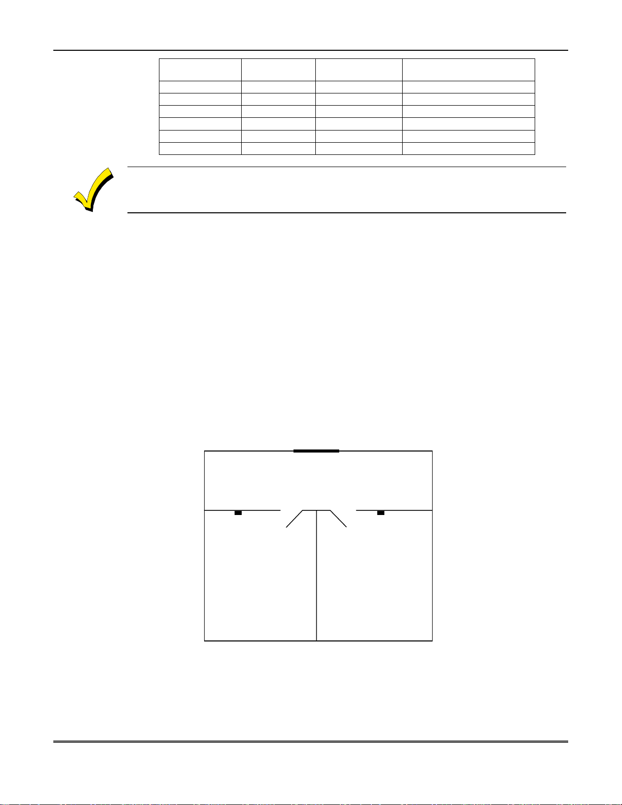
Common Partition Example
The following figure provides a simple diagram of how a common partition system may be
configured for a small office building. In this figure, the occupants of Office 1 and Office 2
need to enter the building through a common lobby.
To program the system for this type of arrangement, zones and users should be defined as
follows:
1. Assume Zones 2 and 4 are for Windows and code these zones as an INSTANT ALARM
TYPE.
2. Assume Zones 1 and 3 are Interior Doors and code these zones as EXIT/ENTRY.
MAIN ENTRANCE
COMMON LOBBY
PARTITION 8 - ZONE 5
KEYPAD KEYPAD
OFFICE # 1
PARTITION 1
ZONES 1 AND 2
OFFICE # 2
PARTITION 2
ZONES 3 AND 4
2–4
Page 11

U
L
Section 2 - System Overview
3. Assume Zone 5 is the Main Entrance Door and code this zone as EXIT/ENTRY. (The
Entry/Exit Delay for this zone must be adequate for the user to enter the main door, pass
through the lobby, and enter their office to disarm the system from their keypad.)
4. Provide User 1 with access to partitions 1, 2, and 8.
5. Provide User 2 with access to partitions 1 and 8.
6. Provide User 3 has access to partitions 2 and 8.
With this programming in th e system and the system armed, when User 2 enters through
the main entrance and into office 1 to disarm the system, the disarming of partition 1 will
also disarm partition 8 and partition 2 will remain in an armed state. With the system
armed, when User 3 enters through the main entrance and into office 2 to disarm the system,
the disarming of partition 2 will also disarm partition 8 and partition 1 will remain in an
armed state.
When the first user exits the building and arms their partition, only their partition will be
armed because the other office is still disarmed. When the last user exits and arms their
partition, partition 8 will also arm.
If a partitioned or double area installation is configured, UL requires that the following installation
requirements be observed.
1. All partitions or areas
2. All partitions or areas
3. The audible alarm device(s)
areas.
4. The control cabinet itself
that any unauthorized access to the control cabinet will cause an alarm.
must be
must be
must be
must be
owned and managed by the same person(s).
part of one building at one street address.
placed where it/they can be heard in all partitions or
tamper protected and connected to a 24-hour type zone so
2–5
Page 12

XL-4, XL-4B, and XL-5 LCD Keypad Programming Manual Version 4
2–6
Page 13

SECTION 3
Programming Mode - LCD Keypad
••••••••••••••••••••••••••••••••••••••••••••••••••
In This Section
Entry Into Keypad Programming Mode
♦
Exit From Programming Mode
♦
••••••••••••••••••••••••••••••••••••••••••••••••••
Entry Into Keypad Programming Mode
LCD Keypad programming can be entered as follows:
Where
:
[CODE] is the CODE key on the keypad
[✴] Is the Asterisk key on the keypad
[INSTALLER CODE] is the six-digit installer code reserved for entry to installer
[1] The digit 1 on the keypad
During keypad programming the function keys perform different functions. See section 4 of
this manual for further information.
Exit From Programming Mode
After performing the desired system programming, the session can be terminated as follows:
Press the SHIFT and ABORT keys (
from the programming state and return to normal operation.
If ✴ and # are depressed too long, keypad panic will be tripped.
[CODE] [
functions such as keypad programming.
SHIFT + ABORT (Also known as the
] [INSTALLER CODE] [1]
✴
and #) at the same time.
✴
✴
The control panel will exit
and # keys)
3–1
Page 14

XL-4, XL-4B, and XL-5 LCD Keypad Programming Manual Version 4
3–2
Page 15
SECTION 4
Function Keys
••••••••••••••••••••••••••••••••••••••••••••••••••
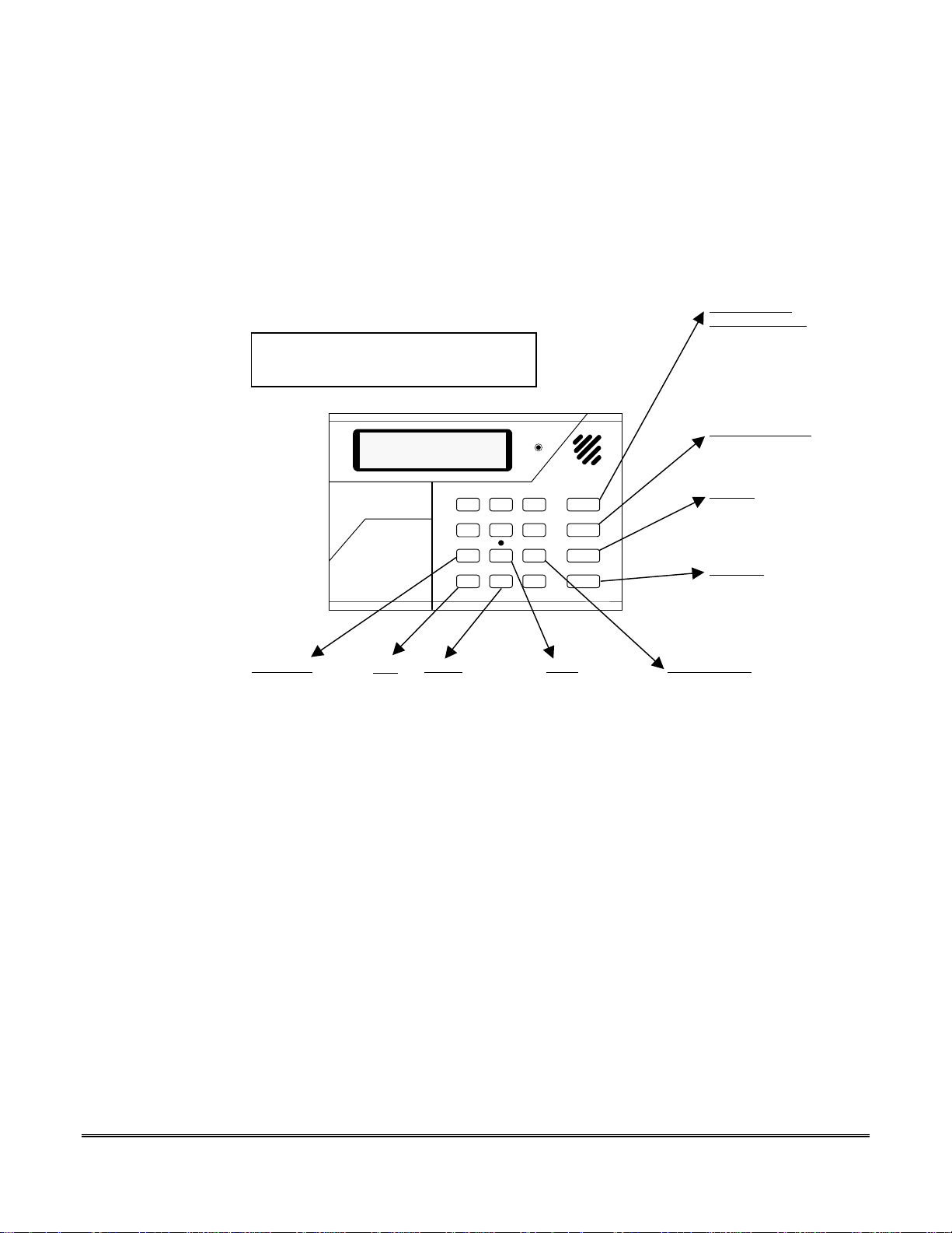
When the control panel has been placed into programming mode the keys have a dedicated
meaning. The keystrokes used during keypad programming are summarized below:
LCD KEYPAD PROGRAMMING
ENTER: CODE ✴ [Installer Code] 1
EXIT: ✴ #
Next Letter
Advances to next
character
[ ✴ 7 for rapid
scroll]
7 to stop
(Press ✴ and # at the same time)
1 2 3
4 5 6
7 8 9
✴
Shift
Toggle
Advances between
choices (ex.
YES/NO)
0 #
STAY
BYPASS
INSTANT
CODE
Erase
✴
8 Will erase
from current
position to EOL
[Text/num fields ]
Next Question/
Jump to Question
Advance to the next
programming
question.
[✴ STAY to jump to
another question]
Previous Question
Go to previous
programming question.
Forward
Advance to next
data entry field on
display.
Backward
Move to previous
data entry field on
display.
Previous Letter
Moves to previous
character
[ ✴ 9 for rapid
scroll]
9 to stop
NEXT QUESTION [STAY KEY]
This function key processes the information entered on the display and advances to the next
programming display. The next display depends on the response made to the current
question. The questions have been organized to skip questions that are not necessar y based
on previous responses. For example, if a secondary receiver telephone number is not defined,
then the related questions dealing with the secondary number will be skipped. Therefore, do
not be alarmed if the NEXT QUESTION key does not always obtain the next sequential
question number.
PREVIOUS QUESTION [BYPASS KEY]
The PREVIOUS QUESTION key will sequence the display backward to the previous
question of the programming sequence. This key can be used scroll backwards through the
questions.
FORWARD [INSTANT KEY ]
Advances the cursor position toward the right within the second line of the display. The
forward key does not change information. If the question type a numerical or text then the
4–1
Page 16

XL-4, XL-4B, and XL-5 LCD Keypad Programming Manual Version 4
FORWARD key will advance the cursor to the right by one position. If the display contains
multiple Yes/No questions then the forward key will move the cursor to the next slot on the
display. If the display contains text, then the forward key will advance to the next character.
BACKWARD [CODE KEY]
Similar to the forward key except that the cursor will be moved to the previous position.
NEXT LETTER [7 KEY]
The NEXT LETTER key is used only for text questions. Text questions request entry of
characters. This includes the letters A-Z, numbers 0-9, space character as well as the other
characters that would normally be seen on a typewriter or computer keyboard. Entry of text
information is accomplished through use of the next letter key. The cursor must be
positioned to the desired position and the next letter key will advance the display through
the character set one character at a time. When the desired character has been reached hit
the FORWARD key to advance the cursor to the next position. When all the desired entries
have been completed for the text field hit the NEXT QUESTION key.
In addition to the NEXT LETTER key advancing one character at a time, depression of the
SHIFT (✴) key followed by the NEXT LETTER ( 7 ) key will advance through the character
sequence more rapidly. When the desired character has been reached depress the NEXT
LETTER (7) key again to stop the display.
The character sequence includes the letters A - Z along with the following:
A - Z { | } space ! " # $ % & ` ( ) ✴ + , - . / 0 1 2 3 4 5 6 7 8 9 : ; =? @
Alphabetic characters can be entered as lower case or upper case values.
ERASE FLD [8 KEY]
The ERASE FIELD function is performed by depressing the SHIFT key (labeled ✴ in normal
operation) followed by the ERASE FIELD key (normally the 8 key). This will blank out the
entire field from the current cursor position to the end of the field and applies only to
numerical and text fields only.
NOTE: After the SHIFT key is depressed, the Arm light will be lit.
PREV LETTER [9 KEY]
The PREVIOUS LETTER is similar to the NEXT LETTER key, however scrolls backward
through the character set for text entry. The character sequence begins with the last letter
accessed by the syste m .
In addition to the PREVIOUS LETTER key advancing one character at a time, depression of
the SHIFT key followed by the 9 key will advance through the character sequence rapidly.
This will make one complete pass through the character set. When the desired character has
been reached depress the 9 key to stop the display.
TOGGLE [0 KEY]
The TOGGLE key is used for YES/NO q uestions and multiple-choice displays. The toggle key
will advance the second line of the display through the available choices for the question. For
example, in a YES/NO question the TOGGLE key will change the answer from YES to NO if
the initial value was YES. The second line of the LCD display shows the current value. The
toggle key advances the display through the available choices for the programming question.
After the last available choice has been reached, the display will return to the first choice.
When the desired choice has been obtained, the NEXT QUESTION key will finalize the entry
and advance to the next disp lay.
4–2
Page 17

SECTION 5
Display Format
••••••••••••••••••••••••••••••••••••••••••••••••••
Installer programming of the system is performed through a series of questions appearing in
the two-line display area of the LCD keypad.
The display area of the LCD keypad has the following format during Installer Programming;
NNN TTTTTTTTTTTT
VVVVVVVVVVVVVVVV
Where:
NNN
The programming questions are assigned sequentially and are grouped together based on th e
type of question. In addition any programming question can be accessed directly using this
sequence number. Some of the questions contain multiple displays to define all of the
attributes. For example, there are multiple displays required to define the char acteristics of
all of the zones.
TTTTTTTTTTTTT
Up to twelve characters to describe the question being asked. Due to space limitations some
question titles are abbreviated. If the question deals with an area containing multiple offsets
such as zones or users then the display will contain a reference to the particular value being
defined (example Z063 for zone #63). For a complete explanation of each programming
question consult section LCD Keypad Programming section of this manual.
VVVVVVVVVVVVVVVV
Displays the current contents of the question. This information can be viewed or modified.
The questions consis t of the following types: Multiple Choice, Yes/No, Numerical,
Hexadecimal, or Text.
If the question contains more than sixteen characters then a second display will appear when
inputting a value greater than sixteen characters. This secondary display contains a left
arrow in the last position of the first line indicating continuation of the first display. This
relates primarily to the telephone numbers, which can contain up to 32 digits.
Question number (000-255.)
Question Text
Value
5–1
Page 18

XL-4, XL-4B, and XL-5 LCD Keypad Programming Manual Version 4
5–2
Page 19

SECTION 6
Question Selection Modes
••••••••••••••••••••••••••••••••••••••••••••••••••
In This Section
General
♦
Sequential Method
♦
Direct Method
♦
••••••••••••••••••••••••••••••••••••••••••••••••••
General
The keypad programming quest ions can be obtained either sequentially or directly as
described in the following paragraphs.
In order to use either question selection method you must already be in the Installer Keypad
Programming mode.
Sequential Method
A fast method to scroll through the sequence of programming questions involves the
successive use of the NEXT QUESTION (or STAY) key. This will advance forward through
the programming questions in sequential order without changing any of the current values.
The questions presented will depend on the Installer Programming level and the values in
previous questions.
FORMAT:
Direct Method
Using the direct method any specific programming question can be obtained through the
question sequence number. This method provides instant access to any programming
question through the three-digit sequence number. A master listing containing all the
programming questions can be found later in this manual.
FORMAT:
where:
SHIFT NEXT QUESTION is the depression of the SHIFT [✴] key followed by NEXT
QUESTION [STAY] function key.
NNN is the three-digit sequence number of the question desired.
NEXT Q. NEXT Q. NEXT Q
SHIFT NEXT QUESTION NNN
The system must already be in the Programming mode.
6–1
Page 20

XL-4, XL-4B, and XL-5 LCD Keypad Programming Manual Version 4
EXAMPLE: SHIFT NEXT QUESTION 003
After depressing the SHIFT key followed by the NEXT QUESTION key the following display
will appear:
DIRECT ACC. MODE
ENTER QUES.#_
Enter 0 0 3. This will obtain question number 003 as follows;
003 CS#1 PH. #
234
In this particular example, the primary Central Station telephone number question was
obtained. At this point, the contents of this field can be modified or another question can be
obtained. If the question requested belongs to an area that contains multiple offsets then the
direct access method will first obtain the selection display for that group. Specifically, this
applies to the following groups:
USERS
ALARM TYPES
TROUBLE TYPES
ZONE DEFINITIONS
KEYPAD CONDITIONS
PARTITION KEYPAD DEFINITION
For example, if requesting the Zone CS Code question, the Zone selection question will first
appear. After entry of the desired zone, the first question will appear for that zone.
6–2
Page 21

SECTION 7
Programming Questions Overview
••••••••••••••••••••••••••••••••••••••••••••••••••
The LCD keypad programming questions have been organized into the following functional
categories:
CENTRAL STATION COMMUNICATIONS [Questions 001 - 024]
This area defines the telephone numbers and dialing options for the control panel to
communicate with a Central Station and the remote programming devices.
USER DEFINITION [Questions 025 - 030]
Defines the characteristics of the users maintained within the panel. This includes the
authorization levels, CS reporting codes and partition assignment.
SYSTEM ATTRIBUTES [Questions 031 - 066]
Defines the values that are common to all zones and partitions within the control panel.
SYSTEM TIMING [Questions 067 - 082]
Contains the various programmable timing features (delays and time-outs).
SYSTEM FUNCTION CODES [Questions 083 - 107]
System function codes specify the codes transmitted to the Central Station for various
conditions.
ALARM TYPES [Questions 108 - 128]
Alarm types are used to define the reporting codes and characteristics for different alarm
conditions. When setting up a zone an alarm type will be necessary. The system contains up
to sixteen alarm types.
TROUBLE TYPES [Questions 129 - 141]
Trouble types are used to define the reporting codes and characteristics for different trouble
conditions. When setting up a zone a trouble type will be requested. The system contains up
to eight trouble types.
ZONE DEFINITION [Questions 142 - 172]
The XL-4 and XL-4B contains eight to sixteen hardwired zones and up to 64 multiplex zones
while the XL-5 contains eight to sixteen hardwired zones and up to 120 multiplex zones. The
zones are fully programmable and the zone definitions are used to customize the zones to
suit your needs.
KEYPAD CONDITIONS [Questions 173 - 178]
In addition to the hardwired zones, conditions can be activated through the keypad for
situations such as FIRE, PANIC, MEDICAL, and DURESS. This section as ks the questio ns
to tailor these conditions to your installation.
PARTITION ASSIGNMENT [Questions 179 - 183]
The control panel can be configured to look like multiple systems to the Central Stations. In
this section defines the keypads that are assigned to each partition.
7–1
Page 22

XL-4, XL-4B, and XL-5 LCD Keypad Programming Manual Version 4
AUTO-DUMP PARAMETERS [Questions 184 - 194]
One feature of the system is the capability to transmit a log of system activity to a local or
remote serial printer. These questions define the frequency of this transmission (daily,
weekly, and monthly) along with text to identify each account.
7–2
Page 23

SECTION 8
LCD Keypad Programming Questions
••••••••••••••••••••••••••••••••••••••••••••••••••
In This Section
General
♦
CS Communications
♦
User Definition
♦
System Attributes
♦
System Timing
♦
System Function Codes
♦
••••••••••••••••••••••••••••••••••••••••••••••••••
Alarm Types
♦
Trouble Types
♦
Zone Definition
♦
Keypad Conditions
♦
Auto Dump Parameters
♦
General
This section describes keypad programming and applies to the XL-4, XL-4B, and XL-5
systems. The sample displays in this section show the format of the keypad programming
questions. The valu es that are displayed are meant to demonstrate the type of input for each
question rather than the default values. The factory default values for the programming
questions are shown in the appropriate section of this manual. NOTE:
can only be performed through a LCD keypad.
Keypad programming
CS Communications
The following paragraphs define programming procedures for telephone numbers and dialing
options for control panel communication with a Central Station receiver and remote
programming devices.
Callback Telephone Number
001 CALLBACK #
_
The system can be programmed and operated remot ely from the Alarm Company location.
This optional two-way capability includes remote programming (uploading, downloading)
and remote commands.
All remote activations are performed over a dedicated telephone line at the Alarm Company
known as the Callback Number. This number should be common to all control panels
installed or maintained by the same company. The callback capability is only an option and
is not required in order to perform remote operations. Enter the Callback Number that will
represent the fixed telephone number dedicated to your EZ-MATE PC Downloader within
your alarm company.
The Callback number is an additional security feature that prevents unauthorized stations
from accessing your control panels. If the Callback number is left blank then the panel will
not call back the Alarm Company location during remote communications, allowing remote
communication with the alarm company after validation of the Central Station ID code.
The Callback telephone number should not be confused with the Central Station Receiver
numbers. In addition, if the device will never be operated remotely, then the Callback Number
should be left blank.
8–1
Page 24
XL-4, XL-4B, and XL-5 LCD Keypad Programming Manual Version 4
Telephone Number Entry
All phone number should be entered with any area codes or access characters needed to dial
the telephone number from the control panel location. The valid digits for all phone numbers
are 0- 9,B, C, or D. The phone digits are entered as follows:
0-9 Actual telephone number digits
B (Shift 2) ✴
C (Shift 3) 3 Second delay
D (Shift 4) #
The SHIFT key is the ✴ (asterisk) shift key on the keypad as shown on the programming overlay.
Do not enter blanks or separators between the digits as this will be interpreted as the end of
the telephone number. A totally blank phone number indicates that the phone number does
not exist. For example, a blank CS#2 Phone number indicates that the panel does not
communicate with the secondary Central Station.
To blank out an existing telephone number move the cursor to the first position and depress
the SHIFT key (✴) followed by the 8 key. To advance the next programming question press
the NEXT QUESTION (or STAY) key. Telephone numbers within the control panel can
contain up to 32 digits. Since the LCD display contains only sixteen characters a secondary
display will automatically appear if a phone number greater than 16 characters is entered.
This secondary display will be denoted with a small left arrow in the last position of the first
line.
Dump Telephone Number
002 DUMP PH. #
_
The control panel stores the last 128 events that have occurred. This system log information
can be viewed by an Installer through a LCD keypad, remotely read by the EZ-MATE PC
Software, or dumped automatically to a remote serial printer. The remote printer can be
located at the Alarm Company, Central Station or other remote location The DUMP
telephone number defines the telephone number of this remote printer and modem and can
vary from account to account.
In addition the system log can be output to a local serial printer. In order to utilize the local
serial printer leave the DUMP phone number blank (enter ✴ 8 to clear a phone number).
The local printer function requires use of the Seria l Print er Interfac e mod ule (mod el 713 0).
If the panel should not transmit system log information then leave this question blank. The
DUMP telephone number can contain up to 32 digits. Additional information for the Auto
Dump function is defined in questions 184-194. The Auto Dump feature requires a modem or
module 7130 and serial printer capable of 300-baud operation.
8–2
Page 25

Primary Central Station Receiver
003 CS1 PH. #
234
The system can transmit digital alarm signals to two separate Central Station numbers.
Enter the complete telephone number of the primary Central Station receiver line. The
telephone number should be entered with the correct area code or access control digits
necessary to dial the Central Station receiver from the panel location.
The primary CS receiver (CS#1) telephone number can contain up to 32 digits. If the panel
does not communicate with the primary Central Station or the panel is being used in a local
only application (see question 016) then leave this question blank.
To erase an entire existing telephone number, position the cursor at the first digit and
depress the SHIFT key (✴) followed by the 8 key.
See the Callback Number for a full explanation of telephone number entry.
CS#1 Receiver Type
004 TYPE CS1
FBI SUPER 2300HZ
The control panel transmits in a variety of DTMF and pulse formats to the Central Station
receiver. This question selects the type of CS transmission made to CS#1. The valid options
are:
Section 8 - LCD Keypad Programming Questions
FBI SUPER 1400HZ FBI Superf ast Fo rmat 1400 HZ Handsh ake
FBI SUPER 2300HZ FBI Superf ast Fo rmat 2300 HZ Handsh ake
ADEMCO Point ID ADEMCO Point ID format
4x2 Express ADEMCO 4x2 Express format
BFSK 2300 RADIONICS BFSK 2300HZ handshake
10P 1400 STAND 10 Pulses Per Second, 1400 Hz handshake, Standard Format
10P 2300 STAND 10 Pulses Per Second, 2300 Hz handshake, Standard Format
10P 1400 ACC+2 10 Pulses Per Second, 1400 Hz handshake, 3x2 or 4x2 Format
10P 2300 ACC+2 10 Pulses Per Second, 2300 Hz handshake, 3x2 or 4x2 Format
10P 1400 EXTEND 10 Pulses Per Second, 1400 Hz handshake, Extended Format
10P 2300 EXTEND 10 Pulses Per Second, 2300 Hz handshake, Extended Format
10P 1400 PART EX 10 Pulses Per Second, 1400 Hz handshake, Partial Extended
10P 2300 PART EX 10 Pulses Per Second, 2300 Hz handshake, Partial Extended
20P 1400 STAND 20 Pulses Per Second, 1400 Hz handshake, Standard Format
20P 2300 STAND 20 Pulses Per Second, 2300 Hz handshake, Standard Format
20P 1400 ACC+2 20 Pulses Per Second, 1400 Hz handshake, 3x2 or 4x2 Format
20P 2300 ACC+2 20 Pulses Per Second, 2300 Hz handshake, 3x2 or 4x2 Format
20P 1400 EXTEND 20 Pulses Per Second, 1400 Hz handshake, Extended Format
20P 2300 EXTEND 20 Pulses Per Second, 2300 Hz handshake, Extended Format
20P 1400 PART EX 20 Pulses Per Second, 1400 Hz handshake, Partial Extended
20P 2300 PART EX 20 Pulses Per Second, 2300 Hz handshake, Partial Extended
40P 1400 STAND 40 Pulses Per Second, 1400 Hz handshake, Standard Format
40P 2300 STAND 40 Pulses Per Second, 2300 Hz handshake, Standard Format
40P 1400 ACC+2 40 Pulses Per Second, 1400 Hz handshake, 3x2 or 4x2 Format
40P 2300 ACC+2 40 Pulses Per Second, 2300 Hz handshake, 3x2 or 4x2 Format
40P 1400 EXTEND 40 Pulses Per Second, 1400 Hz handshake, Extended Format
40P 2300 EXTEND 40 Pulses Per Second, 2300 Hz handshake, Extended Format
8–3
Page 26
XL-4, XL-4B, and XL-5 LCD Keypad Programming Manual Version 4
40P 1400 PART EX 40 Pulses Per Second, 1400 Hz handshake, Partial Extended
40P 2300 PART EX 40 Pulses Per Second, 2300 Hz handshake, Partial Extended
Use the 0 key to toggle through the available choices.
The following receivers/formats are compatible for UL listed systems:
FBI Model CP220: All formats except 4x2 Express
ADEMCO Model 685: All formats except FBI Superfast
Silent Knight Model 9000: 10PPS, Standard no Parity
This question will be skipped if signals are not transmitted to CS#1 (Question 003).
CS Format Examples
The control panel can transmit a variety of formats to the Central Station. Listed below is an
explanation of each format and the overall format of the digits transmitted. Further
information concerning the definition of the codes can be located in the appropriate questions
within this manual. Consult your Central Station manager to determine the formats
acceptable to your Central Station.
Point ID (PID) Format
This is a DTMF format that transmits the following information:
ACCT 18 QXYZ GG CCC
Where:
ACCT = Four Digit Account Number
18 = Identifies PID format
Q = Event Type
1 = New Event or Opening
3 = Restore or Closing
6 = Previously reported event
XYZ = Event Code. Dedicated event types exist to designate the type of event. These codes
will generate English language printouts on both the FBI CP220 and ADEMCO 685
receivers. The valid event codes are described in Table 1 - PID Event Codes and Table 3 Zone PID Event codes.
GG = Group or Partition initiating the signal
CCC = Zone or user number (in Decimal), depending on the signal type
This format requires a High/Low handshake frequency from the CS receiver.
8–4
FBI Superfast
DTMF Format transmitting the following information:
ACCT AZZ S
Where:
ACCT = Four Digit Account Number
Page 27

Section 8 - LCD Keypad Programming Questions
A = Alarm Type (Burglary, Fire, etc.)
ZZ = Zone number (in Hexadecimal)
S = Signal Type (Bypass, Restore, Trouble, etc.)
Select the required handshake frequency: 1400HZ or 2300HZ.
4x2 Express
DTMF format transmitting a four-digit account number followed by a two-digit event code.
Example: 1234 35
This format requires a High/Low handshake frequency from the CS receiver.
Standard Format
Typically involves a 3 or 4 digit account number followed by a single digit event code.
Examples: 123 3, or, 5434 2.
Extended Format
Transmits two lines of information. The first line usually includes the account number (3 or 4
digits), event code, parity bit (if selected), repeats the 3 or 4 digit account number, and
repeats the event code. The second line repeats the event code equal to the number of digit s
in the account number before identifying the zone (or condition) code. In the following
example, the account number is 1234, event code is E, parity bit is P, and zone or condition is
7.
Example:
1234 E P 1234 E
EEEE 7
Partial Extended
The partial extended format transmits a standard signal for alarm conditions and an
extended message for restores and other system conditions.
Examples:
Alarm Condition
853 1
Restore Condition
853 E
EEE 1
ACC + 2
This format transmits either a three or four-digit account number followed by a two-digit
event code. This format is sometimes called 4x2 or 3x2 format. Example:
123 43
or
5467 35
8–5
Page 28
XL-4, XL-4B, and XL-5 LCD Keypad Programming Manual Version 4
PID Event Codes
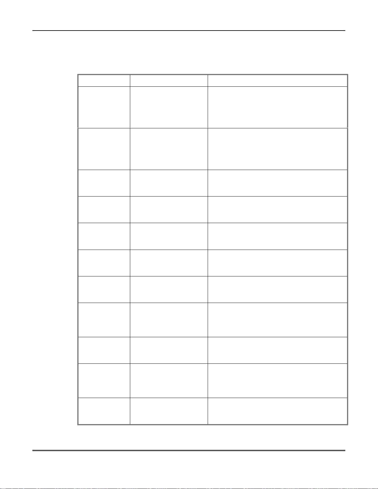
When using ADEMCO PID format, the control panel sends dedicated PID event codes. The
following table lists the PID Event Codes.
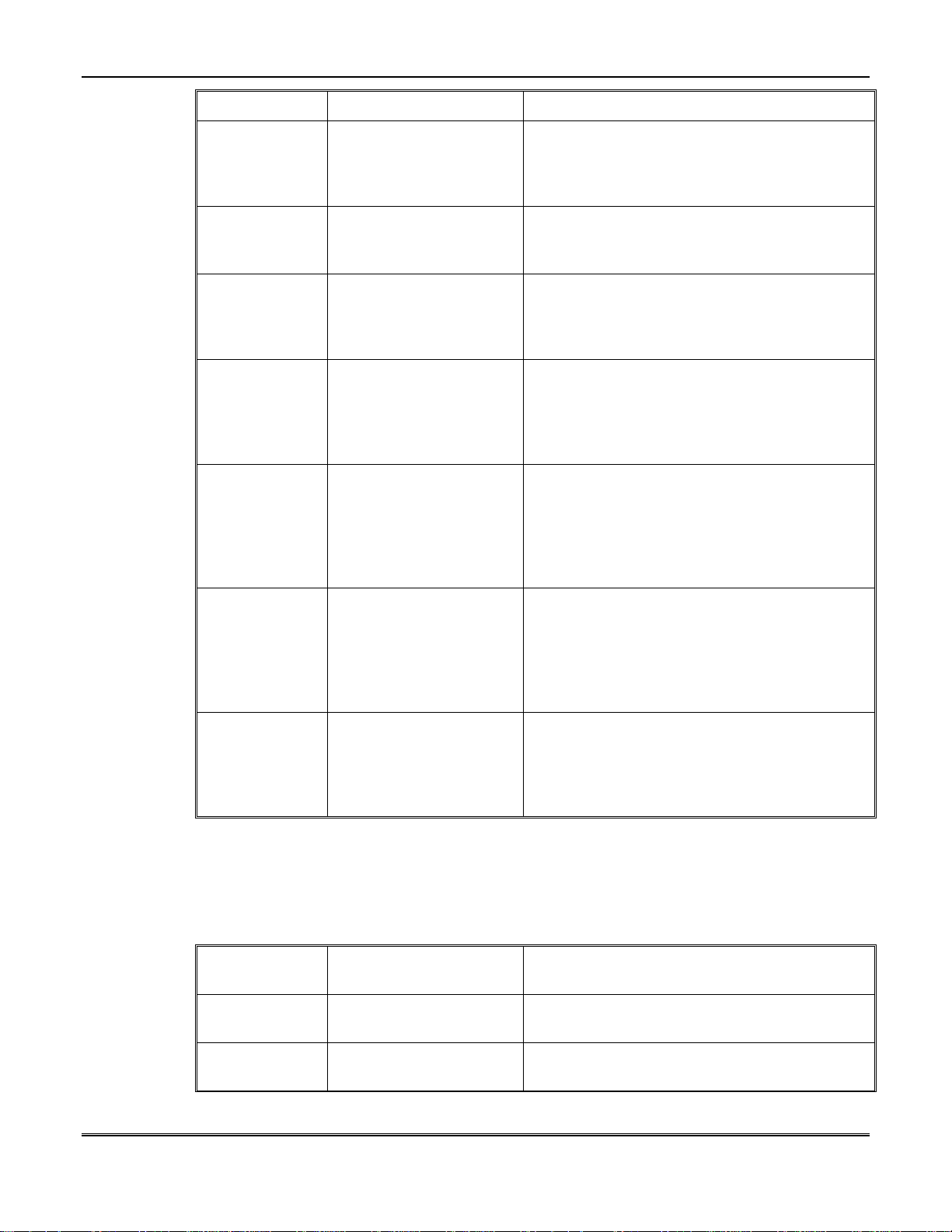
Table 1 - PID Event Codes
EVENT PID EVENT CODE ZONE/POINT/USER #
Opening
Closing
Abort
Cancel
Zone Bypass
Fire Bypass
Dedicated Code, not
programmable; sends 1
“Opening” as Event
Type followed by 402
“Group O/C”
Dedicated Code, not
programmable; sends 3
“Closing” as Event Type
followed by 402 “Group
O/C”
Dedicated Code, not
programmable; sends
406 “Cancel”
Dedicated Code, not
programmable; sends
458 “User on Premise”
Dedicated Code, not
programmable; sends
570 “Zone Bypassed”
Dedicated Code, not
programmable; sends
571 “Fire Bypassed”
Reports programmed 3 digit user CS code
from question #27
Reports programmed 3 digit user CS code
from question #27
Reports programmed 3 digit user CS code
from question #27
Reports programmed 3 digit user CS code
from question #27
Reports programmed 3 digit user CS code
from question #145
Reports programmed 3 digit user CS code
from question #145
24HR. Zone
Bypass
Burg. Bypass
Clock Set
System Test
AC Loss
Dedicated Code, not
programmable; sends
570 “Zone Bypassed”
Dedicated Code, not
programmable; sends
573 “Burglary
Bypassed”
Dedicated Code, not
programmable; sends
625 “Time/Date Set”
Dedicated Code, not
programmable; sends
602 “Periodic Test
Report”
Dedicated Code, not
programmable; sends
301 “AC Loss”
Reports programmed 3 digit user CS code
from question #145
Reports programmed 3 digit user CS code
from question #145
Dedicated Code, not programmable; by #3:
reports #001, by installer: reports #255
Reports programmed 3 digit in CS Test ID
Code from question #93
Reports programmed 3 digit in AC Loss ID
Code from question #94
8–6
Page 29
Section 8 - LCD Keypad Programming Questions
EVENT PID EVENT CODE ZONE/POINT/USER #
Low Battery
System Error
Download
Zone Alarms
Zone Troubles
Dedicated Code, not
programmable; sends
302 “Low System
Battery”
Dedicated Code, not
programmable; sends
300 “System Trouble”
Dedicated Code, not
programmable; sends
306 “Panel Program
Changed”
Programmable
question #146 Zone PID
Code; sends 3 digits
according to the Zone
PID Types
Dedicated Code, not
programmable; sends
373 “Fire Trouble” for
Fire Zones, sends 370
“Protection Loop” for
Burg. Zones
Reports programmed 3 digit in Low Battery
ID Code from question #95
Reports programmed 3 digit in System Error
ID Code from question #96
Reports programmed 3 digit in Download ID
Code from question #97
Reports programmed 3 digit in Zone CS Code
from question #145
Reports programmed 3 digit in Zone CS Code
from question #145
Zone Restores
Keypad
Conditions
Double Digit Event Reporting
The following table lists the Event Codes for double-digit event reporting formats: 3X1 Ext.,
4X1 Ext., 3X2, and 4X2.
EVENT
Opening
Dedicated Code, not
programmable; sends 3
“Restore” as Event Type
followed by
programmable PID Code
(question #146)
Programmable
question #175 Keypad
PID Code; sends 3 digits
according to the Zone
PID Types
Table 2 - Double Digit Event Reporting
FIRST DIGIT OF
EVENT CODE
Quest. #087, Opening
Code; program as 0-F
Reports programmed 3 digit in Zone CS Code
from question #145
Reports programmed 3 digit in Keypad CS
Code from question #174
✴ SECOND DIGIT OF EVENT CODE
Quest. #027, User CS Code; program as 000015: reports as 0-F
Closing
Quest. #088, Closing
Code; program as 0-F
Quest. #027, User CS Code; program as 000015: reports as 0-F
8–7
Page 30
XL-4, XL-4B, and XL-5 LCD Keypad Programming Manual Version 4
EVENT
Abort
Cancel
Bypass
Clock Set
System Test
AC Loss
Low Battery
FIRST DIGIT OF
EVENT CODE
Quest. #086, Abort
Code; program as 0-F
Quest. #090, Cancel
Code; program as 0-F
Quest. #084, Bypass
Code; program as 0-F
Quest. #089, Clock Set
Code; program as 0-F
Quest. #092, System
Test Funct. Code;
program as 0-F
Quest. #131, AC Loss
Trouble Type CS Code;
program as 0-F
Quest. #131, Low
Battery Trouble Type
CS Code; program as 0F
✴ SECOND DIGIT OF EVENT CODE
Quest. #027, User CS Code; program as 000015: reports as 0-F
Quest. #027, User CS Code; program as 000015: reports as 0-F
Quest. #145, Zone CS Code; program as 000015: reports as 0-F
Dedicated Code; by installer mode reports
as 1; by #3 reports as F
Quest. #093, System Test CS Code; program
as 000-015: reports as 0-F
Quest. #094, AC Loss CS Code; program as
000-015: reports as 0-F
Quest. #095, Low Battery CS Code; program
as 000-015: reports as 0-F
System Error
Download
Zone Alarms
Zone Troubles
Zone Restores
Keypad
Conditions
✴ Note: Due to the limitation of representing hexadecimal numbers using a single digit, a
maximum of 16 zones and 16 users can be reported.
Quest. #131, System
Error Trouble Type CS
Code; program as 0-F
Quest. #097, Download
Funct. Code; program as
0-F
Quest. #110, Alarm
Type CS Code; program
as 0-F (Find Alarm Type
for zone in quest. #158)
Quest. #131, Trouble
Type CS Code; program
as 0-F (Find Trouble
Type for zone in quest.
#159)
Quest. #111, Alarm
Type CS Restore Code or
quest. #132, Trouble
Type CS Restore Code;
program as 0-F
Quest. #110, Alarm
Type CS Code; program
as 0-F (Find Alarm Type
for condition in quest.
#177)
Quest. #096, System Error CS Code; program
as 000-015: reports as 0-F
Quest. #098, Download CS Code; program as
000-015: reports as 0-F
Quest. #145, Zone CS Code; program as 000015: reports as 0-F
Quest. #145, Zone CS Code; program as 000015: reports as 0-F
Quest. #145, Zone CS Code; program as 000015: reports as 0-F
Quest. #174, Keypad Condition CS Code;
program as 000-015: reports as 0-F
8–8
Page 31
CS#1 Account Size
005 CS1 ACC SIZE
4 DIGIT ACC
This question indicates whether a three or four digit account number will be transmitted to
CS#1. If a three-digit account number is selected then any fourth digit will be ignored.
Depression of the 0 key will toggle between 3 and 4-digit account number.
The actual account number transmitted to the Central Station #1 is defined in question 182.
The FBI Superfast, 4x2 Express, and ADEMCO PID (point ID) formats utilize a four-digit account
number.
CS#1 Parity Selection
006 PARITY CS1
YES
Enter the desired parity setting for CS#1 transmissions. Parity is an error detection scheme
that is used in certain CS transmission formats. If you are unsure about the parity setting
for your receiver please contact your Central Station manager.
Section 8 - LCD Keypad Programming Questions
This question will be skipped if signals are not transmitted to CS#1 (question 003).
Sescoa Format CS#1
007 SESCOA
NO
This question indicates whether the Sescoa format for fixed digit timing will be transmitted
to CS#1. Depression of the 0 key will toggle between YES and NO. Note: This only applies to
the various pulse based CS transmission formats and will be skipped if signals are not
transmitted to CS#1 (question 003).
U
L
Secondary Central Station Receiver
This option shall not be used for UL listed systems.
008 CS2 PH. #
_
The control panel can transmit digital alarm signals to two separate Central Station
numbers. Enter the complete telephone number of the secondary Central Station receiver
line. The telephone number should be entered with the correct area code or access control
digits necessary to dial the Central Station receiver from the panel location.
The secondary CS receiver (CS#2) telephone number can contain up to 32 digits. If the panel
does not communicate with the secondary Central Station or the panel is being used in a
local only application (see question 016) then leave this question blank.
8–9
Page 32

XL-4, XL-4B, and XL-5 LCD Keypad Programming Manual Version 4
To erase an entire existing telephone number, position the cursor at the first digit and
depress the SHIFT (✴) key followed by the 8 key. See the Callback Number for a full
explanation of telephone number entry. For explanations of the CS transmission formats see
question 004.
CS#2 Receiver Type
009 TYPE CS2
FBI SUPER 2300HZ
The control panel transmits in a variety of DTMF and pulse formats to the Central Station
receiver. This question selects the type of CS transmission made to CS#2. The valid options
are:
FBI SUPER 1400HZ FBI Superf ast Fo rmat 1400 HZ Handsh ake
FBI SUPER 2300HZ FBI Superf ast Fo rmat 2300 HZ Handsh ake
ADEMCO Point ID ADEMCO Point ID format
4x2 Express ADEMCO 4x2 Express format
BFSK 2300 RADIONICS BFSK 2300HZ handshake
10P 1400 STAND 10 Pulses Per Second, 1400 Hz handshake, Standard Format
10P 2300 STAND 10 Pulses Per Second, 2300 Hz handshake, Standard Format
10P 1400 ACC+2 10 Pulses Per Second, 1400 Hz handshake, 3x2 or 4x2 Format
10P 2300 ACC+2 10 Pulses Per Second, 2300 Hz handshake, 3x2 or 4x2 Format
10P 1400 EXTEND 10 Pulses Per Second, 1400 Hz handshake, Extended Format
10P 2300 EXTEND 10 Pulses Per Second, 2300 Hz handshake, Extended Format
10P 1400 PART EX 10 Pulses Per Second, 1400 Hz handshake, Partial Extended
10P 2300 PART EX 10 Pulses Per Second, 2300 Hz handshake, Partial Extended
20P 1400 STAND 20 Pulses Per Second, 1400 Hz handshake, Standard Format
20P 2300 STAND 20 Pulses Per Second, 2300 Hz handshake, Standard Format
20P 1400 ACC+2 20 Pulses Per Second, 1400 Hz handshake, 3x2 or 4x2 Format
20P 2300 ACC+2 20 Pulses Per Second, 2300 Hz handshake, 3x2 or 4x2 Format
20P 1400 EXTEND 20 Pulses Per Second, 1400 Hz handshake, Extended Format
20P 2300 EXTEND 20 Pulses Per Second, 2300 Hz handshake, Extended Format
20P 1400 PART EX 20 Pulses Per Second, 1400 Hz handshake, Partial Extended
20P 2300 PART EX 20 Pulses Per Second, 2300 Hz handshake, Partial Extended
40P 1400 STAND 40 Pulses Per Second, 1400 Hz handshake, Standard Format
40P 2300 STAND 40 Pulses Per Second, 2300 Hz handshake, Standard Format
40P 1400 ACC+2 40 Pulses Per Second, 1400 Hz handshake, 3x2 or 4x2 Format
40P 2300 ACC+2 40 Pulses Per Second, 2300 Hz handshake, 3x2 or 4x2 Format
40P 1400 EXTEND 40 Pulses Per Second, 1400 Hz handshake, Extended Format
40P 2300 EXTEND 40 Pulses Per Second, 2300 Hz handshake, Extended Format
40P 1400 PART EX 40 Pulses Per Second, 1400 Hz handshake, Partial Extended
40P 2300 PART EX 40 Pulses Per Second, 2300 Hz handshake, Partial Extended
Use the 0 key to toggle through the available choices.
8–10
See CS#1 for compatible receivers for UL installations.
Contact the Central Station manager of your monitoring facility to determine the formats
compatible with your Central Station.
This question will be skipped if signals are not transmitted to CS#2 (Question 008).
Page 33
CS#2 Account Size
010 CS2 ACC SIZE
4 DIGIT ACC
This question indicates whether a three or four digit account number will be transmitted to
CS#2. Depression of the 0 key will toggle between 3 and 4-digit account size. If a three-digit
account number is selected then any fourth digit will be ignored.
This question will be skipped if there is no transmission to CS#2 (question 008).
The FBI Superfast, 4x2 Express, and ADEMCO PID (point ID) formats utilize a four-digit account
number.
The actual account number transmitted to the secondary CS is defined in question 183.
CS#2 Parity Selection
011 PARITY CS2
YES
Enter the desired parity setting for CS#2 transmissions. Parity is an error detection scheme
that is used in certain CS transmission formats. If you are unsure about the parity setting
for your receiver please contact your Central Station manager.
Section 8 - LCD Keypad Programming Questions
This question will be skipped if signals are not transmitted to CS#2 (question 008).
Sescoa Format CS#2
012 SESCOA
NO
This question indicates whether the Sescoa format for fixed digit timing will be transmitted
to CS#2. NOTE: This only applies to the various pulse based CS transmission formats and
will be skipped if there is no telephone number defined for CS#2 (question 008).
U
L
Panel Installer Code
This option shall not be used for UL listed systems. This question will be skipped if signals are
not transmitted to CS#2 (question 008).
013 INSTAL CODE
123456
The system contains a series of functions that can only be performed by an authorized
installer. These functions include keypad programming, walk test, time setup, and system
log view.
In order to perform any of these instal ler reserved functions entry of this six-digit installer
code will be necessary. Each alarm company should select a six-digit code in order to secure
their panels from other installers. The code should probably be kept uniform for each Alarm
company. The factory default value for the installer code is 123456. Note: If the default
lockout option (Question #063) is selected then this value will not be overwritten with a
system default. To erase the installer code press ✴ 8.
8–11
Page 34
XL-4, XL-4B, and XL-5 LCD Keypad Programming Manual Version 4
Special care should be made whenever changing the installer code value since subsequent
keypad programming sessions will require the code entered.
Dialing Type
014 DIAL
TONE
Selects the method that this control panel will use to dial the Central Station and is common
to both Central Station phone numbers. Depression of the 0 key will toggle through the
following options:
TONE Touch Tone Dialing
FAST TONE Fast Touch Tone
PULSE Pulse (or rotary dialing)
ADAPTIVE Touch Tone with Pulse Backup
1. The option labeled fast tone transmits the touch tone frequencies at twice the normal speed,
and will automatically revert to normal touch-tone if unsuccessful. This fast tone option may
not be valid in all telephone exchanges. In the ADAPTIVE dialing mode the control panel will
attempt to dial in normal touch tone and if dial tone is not broken revert back to pulse dialing.
2. This question will be skipped if all the telephone numbers are blank.
Dial Tone Detection
015 DIAL TONE
NO
Indicates whether the control panel will look for dial tone before attempting any dialing
attempt. If dial tone detection is selected then the panel will immediately dial if dial tone is
detected. This option can speed up outgoing dialing without the normal delays. If dial tone is
not present then the system will undergo the anti-jam sequence as described in question 023.
If the dial tone detection option is not selected then the system will follow the anti-jam
procedure as described in question 023.
Central Station Dialer Enable
016 DIAL ENAB
YES
This question indicates whether the communicator section will be active for the panel. If the
system is being operated as a local alarm only or the dialer operation should be suspended
enter NO. Default = YES.
Remote Operation
017 REM ENAB
YES
Indicates whether remote actions of any kind will be permitted on this panel. This includes
uploads, downloads, arms/disarms, bypasses and status checks. Remote operations can be
initiated through the EZ-Mate PC downloading software.
Questions 18 - 20 indicate specifically which remote actions will be permitted.
8–12
Page 35
Remote Disarm Enable
018 REM DISARM
YES
Indicates whether this panel can be disarmed remotely through the EZ-MATE PC Based
Downloader. This question provides an additional layer of security for remote operations.
This question will be skipped if the answer to the Remote Operations question 17 is NO. If
the system is programmed for transmission of closing signals then the signal will be sent
after completion of the downloading session.
Section 8 - LCD Keypad Programming Questions
U
L
Remote Arm Enable
Remote Bypass Enable
This question must be answered "NO" for UL listed systems.
019 REM ARM
YES
Indicates whether this panel can be armed remotely through the EZ-MATE PC Based
Downloader. This question provides an additional layer of security for remote operations.
This question will be skipped if the answer to the Remote Operations question 17 is NO. If
the system is programmed for transmission of opening signals then the signal will be sent
after completion of the downloading session.
020 REM BYPASS
NO
Indicates whether this panel can have individual zones bypassed or unbypassed remotely
through the EZ-MATE PC Based Downloader. This question will be skipped if the answer to
the Remote Operations question 17 is NO. If the system is programmed for transmission of
bypass signals, then the signal will be sent after completion of the downloading session.
U
L
Number Of Attempts
U
L
This question must be answered "NO" for UL listed systems.
021 # ATTEMPTS
08 (01-16)
Indicates the number of attempts made by the dialer to reach the Central Station receiver.
Transmission will repeat up until the maximum number of attempts if a transmission is
unsuccessful.
If the Central Station reporting path transmits signals to either receiver telephone numbers
then transmission will alternate between the two numbers if either line is busy.
Default value = 08, 16 means 16 attempts.
For UL Listed applications this shall be programmed for a value between 5 and 10 attempts.
8–13
Page 36

XL-4, XL-4B, and XL-5 LCD Keypad Programming Manual Version 4
Ring Count
022 # RINGS
08 (01-16)
Whenever the Alarm Company attempts to communicate remotely with the system it will
dial the telephone number attached to the control panel. This question determines how many
rings are necessary for this control panel to pickup. NOTE: After the first ring the control
panel will listen into the telephone line to determine whether there is an EZ-Mate
downloader present. If the downloader is present then the control panel will pick up the line,
after the ring count has occurred.
The number of rings should be selected not to interfere with normal operation of the
protected premise. For example, if the system were connected to the existing telephone line
of the location a value of one ring for pickup would probably be undesirable since the panel
would pickup and seize the telephone line every time the premise telephone would ring.
If an answering machine is present at the control panel site, then the number of rings should
be set greater than the number of rings for the answering machine to pickup.
Default value = 8.
Extended Antijam Time
023 EXT ANTIJAM
NO
The control panel contains an anti-jam feature before it performs any communicator dialing.
The anti-jam feature will disconnect the internal telephone line and perform a hang-up on
any external connection. The standard hang-up time is 4 seconds, and the extended option
will hang up for 30 seconds prior to dialing.
The anti-jam time represents the amount of time that the panel will wait between the time
that the dialer has seized the line to the time that the dialing begins.
The anti-jam sequence will be utilized if dial tone detection is not selected or if dial tone
detection is selected and dial tone is not present at the time of dialing (see question 015).
Default = NO.
Extended Acknowledgment
024 EXTENDED ACK
NO
Indicates whether the panel should wait up to 120 seconds for an acknowledgment from the
Central Station receiver, otherwise the panel will wait 30 seconds. Press the 0 key to toggle
between the available choices. Default = NO.
U
L
This option must be programmed as "NO" for UL Listed Systems.
User Definition
The XL-4 and XL-5 control panels contain up to 64 user codes while the XL-5 contains up to
128 user codes. Each user has a unique four-digit user code, an authorization code, partition
assignments, open/close assignments, and a master partition. This section of the Installer
keypad programming is used to setup the authorization levels and user partition
assignments within the panel.
8–14
Page 37

The definition of the actual user codes is not performed within the Installer Keypad Programming
sequence. Definition or modification of user codes can be performed through keypad entry by the
end user or installer or remotely by an authorized operator through the EZ- Mate PC software.
Select User Number
025 SEL USER #
000 000=SKIP
This question indicates the desired user number to be modified. Entry of 000 will skip to the
next group of questions (System Attributes). The XL-4 and XL-4B can contain up to 64
different users while the XL-5 can contain up to 128 different users. The user numbers range
from 001 to 065 for the XL-4 and XL-4B. The user numbers range from 001 to 128 for the XL-
5.
User Authorization Level
026 US LEV #XXX
_ (1-7)
Authorization levels within the control panel determine the functions that each user may
perform within the control panel. The values range from 1 (highest) to 7 (lowest) as defined
below:
Section 8 - LCD Keypad Programming Questions
LEVEL 1 SUPER USER
LEVEL 2 Arm, Disarm, Bypass, Program Users, and Change Partition Assignments in
LEVEL 3 Arm, Disarm, Bypass, and Program Users
LEVEL 4 Arm, Disarm, and Bypass
LEVEL 5 Arm and Disarm
LEVEL 6 DURESS CODE
LEVEL 7 Arm ONLY Code (Maid Code)
Consult the Installation and Setup Guide or User Guide for further information on the
functions performed by various users. NOTE: Users with authorization levels of 1,2 or 3 are
considered Master Users.
User CS Open/Close ID
027 O/C ID #xxx
___ 001- 255
This indicates the digits to be transmitted to the Central Station when this user opens or
closes the premise. The default value for each user CS code will be the user number. If
Open/Close signals are not transmitted or if the reporting format does not transmit O/C by
user ID (example STANDARD) then this value will be ignored.
The user code transmitted to the Central Station may be restricted by the type of
transmission format selected. For example, if you are transmitting in either the standard,
extended or 4x2 formats there is onl y one digit to transmit a user code, therefore you can
only identify user codes in the 0 - 15 range. The Point ID (PID) format will allow you to
transmit any desired user code from 001 - 255.
Arm, Disarm, Bypass, Program Users, Change Partition Assignments in ALL
partitions
own partitions
8–15
Page 38
XL-4, XL-4B, and XL-5 LCD Keypad Programming Manual Version 4
If transmitting in the Point ID Format then enter the exact value you wish to transmit for
the user code. Since the default value is the physical user number then the default value may
be sufficient (example, user number 62 will appear at the receiver as 062).
If a hexadecimal value is desired for transmission (example 4x2, standard or extended
formats), enter the decimal equivalent. For example, to transmit an open/close user ID of B,
enter 011. This will only be required if transmitting a format such as 4x2. Examples: A =
010, B=011, C=012, D=013, E=014, F=015.
User Partition Assignment
028 US PART #XXX
YNNNNNNN
This question defines the partition assignment for this user. Users can be defined for
multiple partitions, which means that their user access codes will be accepted at the keypads
associated with that partition. If the system is being operated as a single partition then all
active users should be defined to partition number 1. If a user is active in more than one
partition then the account number transmitted will depend on the partition where the signal
was initiated.
The FORWARD (INSTANT) and BACKWARD (CODE) keys are used to move the cursor to
the desired position and the TOGGLE (0) key allows YES/NO selection for the partition. For
example, the first position represents partition #1; the second position is partition #2 etc.
If using the common partition feature, user codes should only be enabled in active partitions.
U
L
User Open/Close Transmit Enable
For UL Listed systems, all users shall be assigned to partition 1.
029 O/C EN #xxx
YYYYYYYY
This question indicates whether this user should transmit open/close signals to the Central
Station by partition.
For example, the owner of a partitioned system may have access to all of the partitions,
however signals should only be sent to the CS if this user initiates an opening or closing from
partition number 1. NOTE: All activity will still be maintained within the system log.
The user must also be programmed within the desired partition and an open/close code must
be defined in order for transmission to occur.
The FORWARD (INSTANT) and BACKWARD (CODE) keys are used to move the cursor to
the desired position and the TOGGLE (0) key allows YES/NO selection for the partition. For
example, the first position represents partition #1; the second position is partition #2 etc.
8–16
User Master Partition
030 US MAST #xxx
__ (1-8)
The system contains the capability to define, modify and delete users through the keypad.
This capability is determined by the authorization level of the user (levels 1 - 7 as defined in
question 026). As an additional precaution against users performing modifications across
Page 39

partition boundaries each of these users will contain a master partition value, such that
users with the proper authority level can program only those users that have the same
master partition number.
For example, to prevent authorized users within partition one from changing user codes
assigned to partition two, simply program the users in partition #1 to have a master
partition of one, and the users in partition two to have a master partition of two.
System Attributes
The System Attributes defines the parameters that are common to all zones and partitions
within the control panel.
Expansion Modules
031 EXPAND MODE
NO EXPAND
This question selects which zone expansion module is present in the control panel. Press the
0 key to toggle through the available choices:
NO EXPAND Zone expander slot empty - Control panel contains 8 hardwired zones
8 ZONE EXP. Model 7105 zone expander module is present. Total of 16 zones
Section 8 - LCD Keypad Programming Questions
only.
consisting of the 8 zones on-board and 8 additional hardwired zones
through the expander module.
MUX EXPAND 1 Multiplex expansion module present. Multiplex expansion module
model 7120 is used for the XL-4 and XL-4B and expansion module
model 7126 is used in the XL-5 The system contains 8 hardwired
zones plus up to 64 multiplex points (XL-4 and XL-4B) or 120
multiplex points (XL-5), using a two wire multiplex bus. The
multiplex zones are known as 9 – 72 (XL-4 and XL-4B) or 9 – 128
(XL-5).
The MUX EXPAND 1 option will scan the multiplex bus upon reset
and will find the active points connected to the bus. Using this auto
scan mode, the active devices must be programmed within the
programming sequence to the desired attributes and connected to the
bus and be operational prior to the system reset. NOTE: The reset
occurs during a total power-up or after exiting programming (keypad
or remote).
MUX EXPAND 2 Multiplex expansion module present. Multiplex expansion module
model 7120 is used for the XL-4 and XL-4B and expansion module
model 7126 is used in the XL-5 The system contains 8 hardwired
zones plus up to 64 multiplex points (XL-4 and XL-4B) or 120
multiplex points (XL-5), using a two wire multiplex bus. The
multiplex zones are known as 9 – 72 (XL-4 and XL-4B) or 9 – 128
(XL-5).
Under MUX EXPANDER 2 the valid zones connected to the multiplex
bus are determined by the zone definitions. An active multiplex zone
will be defined as any zone (9 – 72 or 9 - 128) which contains a zone
definition with at least one condition that can cause an alarm/trouble.
See questions 160 - 163. In this mode an inactive zone would be a
zone that would contain the alarm/trouble on open/short questions all
programmed as NO.
8–17
Page 40
XL-4, XL-4B, and XL-5 LCD Keypad Programming Manual Version 4
If any of the expander modules are defined within this question then the module must be
connected to the control panel.
External Relay Modules
032 XTRIG MODE
NO
This question selects if a XL-4705 relay module is connected to the control panel. Press the 0
key to toggle between the available choices.
Open/Close CS Reporting Path
033 OP/CL PATH
NONE
Specifies the transmission path for opening and closing signals. If the system i ncludes
exception reporting then opening and closings mean that the events occurred within the
schedule time for that day. The options are:
CS#1 ONLY Primary rec. only
CS#2 ONLY Secondary rec. only
CS#1 & CS#2 Both receivers always
CS#1 BU CS#2 CS#1 backed up by CS#2
CS#2 BU CS#1 CS#2 backed up by CS#1
NONE No O/C transmissions
Press the 0 key to toggle through the available choices.
The opening and closing reporting path will cover all partitions in a multi-system installation.
U
L
Partition Auto Arming By Day
Openings and closings shall be enabled in UL Listed Commercial Burglary applications.
034 ENAB AUTOARM
NNNNNNNN
This question indicates whether Auto Arming by partition by day should be enabled. To
enable this function for a partition, advance to the partition desired and depress the 0 key
(toggle) to change the N (no) to Y (yes). When this function is enabled, an auto-arming
schedule must be entered into the system. To enter an auto arming schedule proceed as
follows:
1. Exit the programming mode.
2. Enter #3 from the keypad. The keypad will display:
System clock
(1) Clock (2) Arm
8–18
Page 41
Section 8 - LCD Keypad Programming Questions
The clock must be set prior to entering an auto-arming schedule. If the clock is not already set,
refer to the Quick Commands section of the Installation and Setup Guide.
3. Press 2. The keypad will display:
Su Autoarm HR
12:00 a Part 1
The Part number will be the partition number the keypad is enabled in.
4. Set the hour by entering a number from 1 to 12 for the desired hour (HR).
5. Press the Instant key. The HR portion of the display will change to MIN.
6. Set the minute by entering a number from 0 to 59 for the desired minute (MIN).
7. Press the Code key to change from AM (a ) to PM (p). NOTE: The CODE key must be
pressed at least once before you can exit this mode.
8. Press the Stay key to advance to the desired day of the week. Note that if the # key is
pressed while in the auto arm mode, the display will show --:-- meaning that the time is
disabled and there will be no auto arm for that day.
9. Re-enter the programming mode to continue programming.
Clock Set Reporting Path
035 CLOCK PATH
NONE
Specifies the transmission path for the Schedule Change reporting code to the CS. A clock set
signal can be transmitted to the Central station every time the time on the clock is changed
at the keypad. The options are:
CS#1 ONLY Primary rec. only
CS#2 ONLY Secondary rec. only
CS#1 & CS#2 Both receivers always
CS#1 BU CS#2 CS#1 backed up by CS#2
CS#2 BU CS#1 CS#2 backed up by CS#1
NONE No transmission
Press the 0 key to toggle through the available choices.
This reporting path will cover all partitions in a multi-system installation based on the exception
reporting option specified in question 035. The code transmitted for clock set is defined in
question 089.
Test Signal Reporting Path
036 TEST CS PATH
NONE
Specifies to which Central Station the periodic system test signals is transmitted. The
options are:
CS#1 ONLY Primary rec. only
CS#2 ONLY Secondary rec. only
8–19
Page 42
XL-4, XL-4B, and XL-5 LCD Keypad Programming Manual Version 4
CS#1 & CS#2 Both receivers always
CS#1 BU CS#2 CS#1 backed up by CS#2
CS#2 BU CS#1 CS#2 backed up by CS#1
NONE No Test transmissions
Press the 0 key to toggle through the available choices.
U
L
System Test Interval
Test code transmission shall be enabled in UL Listed applications.
037 TEST FREQ
24 HOUR
Indicates the frequency of automatic system test reports. Test reports can be transmitted to
the Central Station on a daily (every 12 or 24 hours) or on a weekly basis. System Test
signals will be transmitted only if a transmission path is specified in question 036. The test
code transmitted,depending on the format selected, is entered in System Test questions
(#092 and #93). The time of day (hour and minute) for transmission of system test is entered
in questions 038 & 039. Press 0 to toggle between the following options:
12 HOUR
24 HOUR
SUNDAY
MONDAY
TUESDAY
WEDNESDAY
THURSDAY
FRIDAY
SATURDAY
8–20
System test will report the account number for partition #1 in a multi-partitioned system.
U
L
Test Time - Hour
The test frequency shall be 12 or 24 hours for UL listed applications.
Enter the hour of the day, in 24-hour time, for transmission of system test signal. For
example, 5PM = 17. The test time is only applicable if there is a test signal and transmission
path defined.
038 TEST TIME HR
23 (00 - 23)
Page 43

Test Time - Minute
039 TEST TIME MN
00 (00 - 59)
Enter the minute within the hour, for transmission of a system test signal.
Download Reporting Path
040 DOWN PATH
NONE
Specifies the Central Station transmission path for a signal confirming a system download.
This signal will be sent upon any valid remote communications connection with the control
panel. This allows the Central Station to be notified upon a remote communications session
(upload/download or remote commands). The options are:
CS#1 ONLY Primary rec. only
CS#2 ONLY Secondary rec. only
CS#1 & CS#2 Both receivers always
CS#1 BU CS#2 CS#1 backed up by CS#2
CS#2 BU CS#1 CS#2 backed up by CS#1
NONE No Download transmissions
Press the 0 key to toggle through the available choices.
Section 8 - LCD Keypad Programming Questions
Bypass Reporting Path
041 BYPASS PATH
NONE
Specifies the Central Station transmission path for system bypasses. The options are:
CS#1 ONLY Primary rec. only
CS#2 ONLY Secondary rec. only
CS#1 & CS#2 Both receivers always
CS#1 BU CS#2 CS#1 backed up by CS#2
CS#2 BU CS#1 CS#2 backed up by CS#1
NONE No Bypass transmissions
Press the 0 key to toggle through the available choices.
Disable Bypass On Stay
042 DIS BYP STAY
NO
Indicates whether a bypass signal transmission will be disabled when performing STAY
arming. If answered as NO then bypasses will be transmitted to the Central Station. If YES
then bypasses will not be transmitted.
In either case, the bypasses will be reflected in the system log. Press the 0 key to toggle
between the available choices.
This question also determines whether bypasses will be transmitted when performing group
bypasses. If answered as NO then individual bypasses will be transmitted to the Central
Station. If YES, then bypasses will not be transmitted when a group bypass is performed.
8–21
Page 44
XL-4, XL-4B, and XL-5 LCD Keypad Programming Manual Version 4
Bypass Transmission Type
043 XMIT BYPASS
ON BYPASS
Specifies when bypasses are transmitted to the Central Station. The options are:
ON BYPASS Transmit at time of bypass
ON ARMING Transmit upon system arming
Bypassing can be enabled or disabled by zone.
U
L
Auto Unbypass Enable
U
L
Arming Output Level
This must be programmed "ON BYPASS" for UL Listed systems.
Press the 0 key to toggle between the available choices.
044 AUTO UNBY EN
YES
Indicates whether bypassed zones will automatically be unbypassed upon system disarm.
Bypasses will be generated for the bypassed zones if a bypass code has been defined. This
option will only unbypass zones if there are no other alarm or trouble conditions present.
This must be programmed "YES" in UL Listed systems.
Press the 0 key to toggle between the available choices.
045 ARM OUT LEV
HIGH
Indicates the desired voltage level on trigger output for arming status. The system contains
one voltage output located on the trigger connector of the control panel that represents the
current arming state for the entire panel. If the system contains multiple partitions then this
output will be at the selected level if any of the partitions are armed. The options are HIGH
and LOW. Press the 0 key to toggle between the available choices.
8–22
Bell Test At Arming
046 BELL TST ARM
NO
Indicates whether a bell test will be performed when the system is armed. Default = NO.
The bell output is assumed to be relay 1, and will only operate with relay 1.
U
L
This must be programmed as "YES" in UL Listed Commercial Burglary applications.
Press the 0 key to toggle between the available choices.
Page 45
Bell Ringback At Closing
047 BELL RBAK
NO
Indicates whether there will be a bell ringback at closing. If YES then the bell (relay 1) will
pulse several times indicating a successful closing signal to the Central Station. If the system
is partitioned then this can occur for each of the partitions. Default = NO. Press the 0 key to
toggle between the available choices.
Sounder Ringback
048 SOUND RBAK
YES
Indicates whether a keypad sounder ringback will occur and applies to all signals
transmitted to the Central Station. This is similar to the bell ringback option described in
the previous question except this involves the keypad sounder. If the system is pa rtitioned
then the sounder ringback will occur at the keypads defined for the partition that has closed.
Default = Yes. Press the 0 key to toggle between the available choices.
Section 8 - LCD Keypad Programming Questions
U
L
Fire Verification
Reset Key Function
For UL applications either question 47 or 48 must be "YES".
049 FIRE VERIF
YES
Indicates whether relay number 2 will be used as a fire (or smoke) reset for the hardwired
zones of the system. If YES then relay #2 will be dedicated to the fire reset function.
If Fire Verification is not used then relay #2 is available for other purposes providing that no
zones are defined for FIRE- SMOKE purposes in qu estion 143.
This question must be set to NO if relay 2 is desired for operation other than as a smoke
detector reset.
If a fire zone is programmed in the system and fire verification is set to NO, the panel will
automatically reset this question to YES.
If four wire smoke detectors are used in conjunction with multiplex adapters then the smoke reset
will originate from relay # 2.
Press the 0 key to toggle between the available choices.
050 ENAB RESET
NO
Indicates whether the system reset function can be performed through depression of the ✴
key. This is an alternative to entry of a valid user code. The RESET function would be used
to acknowledge system activity such as alarms or troubles and to exit the alarm memory
mode.
If YES, then system reset can be performed using the ✴ key or a valid user number. If NO
then only a valid user code is accepted.
8–23
Page 46
XL-4, XL-4B, and XL-5 LCD Keypad Programming Manual Version 4
U
L
Restores To Follow Loop
U
L
In UL Listed systems this option must be "NO".
Press the 0 key to toggle between the available choices.
051 RES FOL LOOP
NO
Indicates whether all restore signals are to follow the loop or after bell cutoff. If NO then
restores occur after the bell cutoff period and the loop has returned to the normal condition,
or if the system is disarmed after alarm and the zone is not recycled. Default = NO.
If selecting this option then the action on abort (question 052) should be programmed for "no
abort".
In UL Listed systems this option must be "NO".
Press the 0 key to toggle between the available choices.
Action On Abort
052 ACT ON ABORT
NO ABORT
Indicates the action to be t aken on an abort. The options are:
ABORT CODE Transmit the abort code instead of the alarm code
STOP DIALING Stop the transmission, send nothing
NO ABORT No abort capability; send alarm code
RESTORE Transmit the restore code instead of the alarm code
Press the 0 key to toggle between the available choices.
The abort action is system wide and will be used for all zones within all partitions.
Additional notes on the ab ort feature:
Only alarms caused by actual zones (not keypad emergency conditions) are abortable. Zones
must have an alarm type specifying a dial delay to be abortable (even if the dial delay time is
set to 0). If dial delay is set to NO in the alarm type then there is no capability to abort the
signal.
Zones are abortable until receipt of handshake All formats (except PID) will transmit the
abort action followed by the zone code. PID format will transmit the cancel code (406) and
the user number.
Multi-Partition Mode
053 CROSS PART
YES
This option enables an authorized user at one keypad to access other partitions within the
system through the # 0 command. Authorized users will be able to view the status of other
partitions and perform commands from the keypad. Press the 0 key to toggle between the
available choices.
8–24
Page 47
Enable Quick Arming
054 QUICK ARM
YES
Indicates whether the quick arming command [ # 1 ] will be available to users of the system.
This enable i s system-wide in a multi-partitioned system.
Quick arming will transmit the CLOSE code, if programmed, along with the first user
number defined for the partition if the transmission format sends a user code.
Enable Quick Forced Arming
055 QUICK F-ARM
YES
Indicates whether the quick forced arming command [ # 2] will be available to users of the
system.
If quick forced arming is enabled then it will be available throughout all partitions of a
multi-partitioned system.
Section 8 - LCD Keypad Programming Questions
Quick forced arming will transmit the CLOSE signal, if programmed for CS transmission,
along with the first user code defined for that partition if the transmission format sends a
user code.
U
L
Secure Forced Arming
U
L
In UL Listed systems this option must be "NO".
Press the 0 key to toggle between the available choices.
056 SECURE F-ARM
YES
This indicates whether the forced arming function will be permitted within the system. The
forced arm sequence requires a user code as follows: BYPASS [User Code] BYPASS. This
applies to all partitions within the system. This option is independent of the quick forced arm
option in the previous question.
In UL Listed systems this option must be "NO".
8–25
Page 48
XL-4, XL-4B, and XL-5 LCD Keypad Programming Manual Version 4
Enable Keypad Zone Directory
057 ZONE DIR
YES
The system has a user initiated keypad function (LCD keypads only) which can scroll
through the zone descriptions for all zones assigned to the partition ( # 4 ). This question
enables or disables the keypad directory function. Press the 0 key to toggle between the
available choices.
Enable Quick Bypass Arming
058 QUICK BYPASS
YES
Indicates whether the quick bypass command [ # 5 ] will be available to users of the system.
NOTE: If quick bypass is enabled then it will be available throughout all partitions of a
multi-partitioned system.
U
L
Enable Chime Control
Super User Enable
In UL Listed systems this option must be "NO".
Press the 0 key to toggle between the available choices.
058 CHME CNTRL
YES
Indicates whether the keypa d option to turn the system chime on and off [ # 6 ] will be
available to users of the system.
If chime control is enabled then it will be available throughout all partitions of a multi-partitioned
system.
Each zone has an individual option to select whether the zone can activate the chime
(question 169). Press the 0 key to toggle between the available choices.
060 SUPER USER
YES
Selects whether user authorization level 1 will be able to alter user partition assignments
within all partitions of the system. Press the 0 key to toggle between the available choices.
8–26
Multi-Partition Operation
061 MULTI PART
ARM/DISARM
Selects the functions that are available through the multi-partition operation command
[# 0 ]. The multi-partition option allows an authorized user to turn any keypad into an active
keypad for any selected partition, or to group arm or disarm the system. Press the 0 key to
toggle through the following multi-partition functions:
ARM/DISARM Allows multiple partition arming and disarming by authorized users.
DISABLED Multi partition function [ # 0 ] is not permitted.
Page 49
TO DISARM Only multiple partition disarming is permitted.
TO ARM Only multiple partition arming is permitted.
7 Digit User Code
062 USER# + CODE
NO
The control panel can be operated with either a four or seven digit user code. This question
indicates whether the user code required throughout the system will be the 4 digit user code
or the User # followed by the user code (seven digit). Default = NO
If YES, then a seven-digit entry will be required for all actions which require a user code. For
example, if user # 7 has a user code of 1234 then that user would enter 0071234 to perform
actions on the system.
This option affects all users for all partitions. Press the 0 key to toggle between the available
choices.
Default Lockout Option
063 CS/INST DEF
YES
This option is known as the default lockout option and determines whether the CSID and
Installer Code will be modified upon initiating a system default. To obtain default lockout
protection, answer NO to this question.
Section 8 - LCD Keypad Programming Questions
If the Default Lockout option is selected then a system default will reset all of the
programmable options except the CSID and the Installer Code. Press the 0 key to toggle
between the available choices.
Keypad Programming
064 KPAD PROG
YES
This question indicates whether keypad programming will be enabled. If keypad
programming is disabled then the system can only be programmed through the EZ-Mate PC
Software package.
If this question is answered as NO you will be unable to reenter keypad programming.
Default = YES. Press the 0 key to toggle between the available choices.
Daylight Savings Time
065 DAYLITE SAV
NO
Indicates whether this location observes daylight savings time. If YES then the syst em will
automatically switch the time when appropriate each season. Press the 0 key to toggle
between the available choices.
AC Line Frequency
066 AC FREQ
60 HZ
Indicates the line frequency of the incoming AC power line. The choices are 60 Hertz or 50
Hertz [Default = 60 HZ]. The 0 key will toggle between the choices of 60hz and 50hz. This
8–27
Page 50
XL-4, XL-4B, and XL-5 LCD Keypad Programming Manual Version 4
question must be answered correctly based on the input power in order to insure an accurate
system time clock.
The standard value for the US is 60Hz.
U
L
In UL Listed systems this option must be 60Hz.
System Timing
The System Timing section allows programming of the various timing options of the control
panel.
Bell Delay Time
Amount of time in 15 second increments prior to activating the bell (relay #1) upon system
activity. The value is specified in steps of 15 seconds from 00 to 14, with 15 meaning an
infinite delay. Example 00 = No delay, 03= 45 second delay.
Each alarm type has a programmable option (question 112) indicating whether the alarm
type adheres to bell delay. This allows certain emergency conditions to bypass the bell delay
if desired.
U
L
In UL Listed systems this option must be 00.
067 BEL DEL 15S
01 (00-15)
8–28
Dialer Delay
U
L
Exit Delay #1
068 DIAL DEL 15S
01 (00-15)
Indicates the amount of time before dialer activation in 15-second intervals. Similar to the
bell delay, an option exists to override the dialer delay for certain conditions.
In UL Listed systems this option must be 00.
069 EXIT DL1 15S
04 (00-15)
Specifies the exit delay in 15-second increments. The exit delay can be defined from 0 to 14
fifteen-second intervals, with 15 indicating an infinite exit delay.
The zone attributes (question # 164) allows selection of the desired exit delay.
Page 51
Section 8 - LCD Keypad Programming Questions
U
L
Exit Delay #2
U
L
Entry Delay #1
This shall not exceed 60 seconds in UL Listed systems.
070 EXIT DL2 15S
04 (00-15)
Specifies the exit delay in 15-second increments. The exit delay can be defined from 0 to 14
fifteen-second intervals, with 15 indicating an infinite exit delay.
The zone attributes (question # 164) allows selection of the desired exit delay.
This shall not exceed 60 seconds in UL Listed systems.
071 ENT DEL1 15S
02 (00-15)
The control panel contains two separate entry time periods. This allows different entry times
for different zones. For example a keypad placed by a garage door might require more time
than a keypad located next to the front door. Each zone allows selection of either entry time
(see question #165).
Specify entry delay #1 in 15 second increments. The entry delay can be defined from 0 to 14
fifteen-second intervals, with 15 indicating an infinite exit delay.
U
L
Entry Delay #2
Specifies entry delay #2 in 15 second increments. The entry delay can be defined from 0 to 14
fifteen-second intervals, with 15 indicating an infinite exit delay. When defining individual
zones an option exists to select entry delay 1 or 2 (see question 165).
U
L
AC Loss Delay
Indicates the time delay in 15-minute intervals for transmission of an AC loss signal. AC
failure must exist for the AC loss period before an AC loss signal will be transmitted.
In UL residential applications the entry delay shall not exceed 45 seconds, or 15 seconds for UL
Commercial Burglary applications.
072 ENT DEL2 15S
04 (00-15)
In UL residential applications the entry delay shall not exceed 45 seconds, or 15 seconds for UL
Commercial Burglary applications.
073 AC LOSS 15MN
01 (00-15)
8–29
Page 52
XL-4, XL-4B, and XL-5 LCD Keypad Programming Manual Version 4
A value of 00 indicates that AC failure should be sent immediately, while a value of 15
indicates that AC loss should never be sent. Default value = 2 (30 minutes).
Exit Triggers
074 EXIT TRG
NNNNNNNN
Indicates whether any of the eight programmable voltage level output triggers will be
activated upon an exit condition. The position of the Y or N indicates the trigger number.
This trigger will be latched for the duration of the exit interval. When the relay module is
enabled in question 032, the position of the Y or N becomes the arming status for partitions 1
though 8 for corresponding relay 1 through 8. Default = NNNNNNNN.
The triggers are active high and go from 0 - 12 volts, 25mA maximum current.
The FORWARD (INSTANT) and BACKWARD (CODE) keys are used to position the cursor
to the desired position while the TOGGLE (0) key will change the Yes/No status of that
trigger. The first position represents trigger #1, the second position trigger #2, etc
Entrance Triggers
075 ENT TRG
NNNNNNNN
Indicates whether any of the eight programmable voltage level output triggers will be
activated upon an entrance condition. The position of the Y or N indicates the trigger
number. This trigger will be latched for the duration of the entrance interval. Default =
NNNNNNNN.
The triggers are active high and go from 0 to 12 volts, 25mA maximum current.
The FORWARD (INSTANT) and BACKWARD (CODE) keys are used to position the cursor
to the desired position while the TOGGLE (0) key will change the Yes/No status of that
trigger. The first position represents trigger #1, the second trigger #2, etc.
Triggers 7 and 8 should be set to N if relay module XL-4705 is enabled.
Cutoff Timer #1
076 TIMEOUT1 1MN
14 (00-15)
The control panel contains three different bell cutoff times that can be selected for the alarm
and trouble types. Enter the duration of timeout #1 in one minute intervals.
Cutoff Timer #2
077 TIMEOUT2 2MN
15 (00-15)
The control panel contains three different bell cutoff times that can be selected for the alarm
and trouble types. Enter the duration of timeout #2 in two minute intervals.
The cutoff timers are selected in the alarm and trouble type and relate to whichever relay is used
for that particular alarm or trouble type.
8–30
Page 53
Cutoff Timer #3
078 TIMEOUT3 3MN
02 (00-15)
The control panel contains three different bell cutoff times that can be selected for the alarm
and trouble types. Enter the duration of timeout #3 in three minute intervals.
The cutoff time selected for the alarm bell in residential applications shall be a 4-minute
minimum.
Section 8 - LCD Keypad Programming Questions
U
L
Global Bell Lockout Counter
U
L
Local Bell Lockout Counter
The cutoff time selected for the alarm bell in UL Commercial Burglary applications shall be a
minimum of 16 minutes.
079 GLOB BELL LK
15 (00-15)
Indicates the total number of bell activations from all zones of the panel that will cause bell
lockout. This counter will be reset with each arming of the system and will only be
incremented by controllable zones that have been defined with the lockout feature enabled
(question #166). The bell lockout feature merely prevents repeating activity from triggering
the bell. Signals will continue to be transmitted to the Central Station in accordance with the
zone definition. If signals are to be suppressed, then the dialer lockout feature should be
considered. Default = 15 (None). If you do not want bell lockout enter 15.
For UL Listed systems this option shall be prog rammed "15".
080 LOC BELL LK
15 (00-15)
Indicates the number of bell activations for an individual zone that will cause a bell lockout.
This counter will be reset with each arming of the system and applies only to burglary zones
that have been defined with lockout enabled (see question #166). Default = 15 (None). If you
do not want bell lockout enter 15.
U
L
Global Dialer Lockout Counter
For UL Listed systems this option shall be prog rammed "15".
081 GLOB DIAL LK
15 (00-15)
Indicates the number of dialer activations from all zones of the panel that will cause a dialer
lockout. This counter will be reset with each arming of the system and applies only to
8–31
Page 54
XL-4, XL-4B, and XL-5 LCD Keypad Programming Manual Version 4
burglary zones that have been defined with lockout enabled. Dialer lockout does not effect
the bell activation. Default = 15 (None).
If multiplex capability is present then the global lockout counter will be used to determine
the number of individual point supervision faults that will lock out the dialer. Default = 15
(None).
If you do not want global dialer lockout enter 15.
U
L
Local Dialer Lockout Counter
U
L
For UL Listed systems this option shall be prog rammed "15".
082 LOC DIAL LK
15 (00-15)
Indicates the number of dialer activations from an individual zone that will cause a dialer
lockout. This counter will be reset with each arming of the system and applies only to
burglary zones that have been defined with lockout enabled.
If multiplex capability is present then the local lockout counter will be used to determine the
number of bus supervision faults that will lock out the dialer. Default = 15 (None).
If you do not want local dialer lockout enter 15.
For UL Listed systems this option shall be prog rammed "15".
System Function Codes
The System Function Codes section defines the codes (0-9, A-F) that will be transmitted to
the Central Station when various conditions occur. The values A-F can be entered into any of
these questions as follows:
8–32
DIGIT KEYSTROKES OR
ASHIFT 1 ✴ 1
BSHIFT 2 ✴ 2
CSHIFT 3 ✴ 3
DSHIFT 4 ✴ 4
ESHIFT 5 ✴ 5
FSHIFT 6 ✴ 6
The SHIFT key is the ✴ (asterisk) key as shown on the programming overlay.
Enable Zone Tamper
083 EN ZONE TAMP
NO
This option determines whether the system will have a tamper zone for each zone. When
enabled, all even zones will report tamper in the partition that the previous odd zone is
Page 55
enabled in. The even zone will display the previous odd zone number and/or description. For
example, if Zone 10 is violated, armed, or disarmed, it will display zone 9 tamper. NOTE: If
this feature is enabled, then the total zone capacity of the system will be reduced by one-half
(for example, a 128 zone system becomes 64 zones plus 64 tampers).
Bypass Code
084 BYPASS CODE
6 ( 0 - F )
Indicates the system reporting code for a bypass. An option exists per zone to determine
whether bypasses are reported. Bypasses will be reported to the Central Station based on the
bypass option selected in question #167.
If transmitting the PID format then the following dedicated bypass codes will be transmitted based
on the type of event:
Zone Bypass 570
Fire Bypass 571
Burg Zone Bypass 573
Bypass Restore Code
085 BYP RES CODE
E ( 0 - F )
Indicates the system reporting code for a bypass restore. An option exists per zone to
determine whether bypasses are reported. Bypasses will be reported to the Central Station
based on the bypass option selected in question #167.
Section 8 - LCD Keypad Programming Questions
If transmitting in PID format then the bypass code transmitted will be the fixed code as
described in the Bypass code question with an indication that the signal is a restore.
Abort Code
086 ABORT CODE
D ( 0 - F )
Indicates the reporting code for an abort. This abort code will only be transmitted if the
action on abort (question #052) specifies Abort. Abort codes will be followed by the zone code
for conventional formats and the user code in the PID format.
If PID format is used then a code of 406 will be transmitted.
Opening Code
087 OPEN CODE
B ( 0 - F )
Indicates the reporting code for an opening. If the system is partitioned then the account
number transmitted to the Central station will depend on the partition where the opening
occurred. In addition if the transmission format selected includes the user code then the user
number will also be included based on the Open/Close transmission path defined in question
033.
8–33
Page 56
XL-4, XL-4B, and XL-5 LCD Keypad Programming Manual Version 4
For PID formats the code transmitted will be 402 with the new event indication.
Closing Code
088 CLOSE CODE
C ( 0 - F )
Indicates the reporting code for a closing. If the system is partitioned then the account
number transmitted to the Central station will depend on the partition where the closing
occurred. In addition if the transmission format selected includes the user code then the user
number will be included based on the transmission path defined in question 033.
For PID format the CLOSE code is 402 with the restore indication.
Clock Set Code
089 Clock CODE
0 ( 0 - F )
This defines the code to be transmitted to the Central Station if any clock set change is
performed at the keypad. This signal will be transmitted based on the reporting path defined
in question 035.
If PID Format is selected then an event code of 625 will be transmitted.
Cancel Code
090 CANCEL CODE
F (0 - F)
This code is transmitted to the Central Station if the system is disarmed after an alarm
condition. If the format supports 2 digits, the second digit will be the user ID that disarmed
the system. This signal will be transmitted based on the reporting path defined in question
091.
If PID Format is selected then an event code of 458 will be transmitted.
Cancel Path
091 CANCEL PATH
NONE
This indicates the CS transmission path for cancel codes. Press 0 to toggle through the
available choices:
CS#1 ONLY Primary Receiver Only
CS#2 ONLY Secondary Receiver Only
CS#1 & CS#2 Both Receivers always
CS#1 BU CS#2 CS#1 backed up by CS#2
CS#2 BU CS#1 CS#2 backed up by CS#1
NONE No cancel transmissions
8–34
Page 57

CS Test Code
092 CS TEST CODE
8 ( 0 - F )
Indicates the reporting code for a s ystem test. The specific type of system test (12 hour , 24
hour or weekly) and the time of system test are defined in questions 037 - 039. Test signals
will be transmitted based on the path defined in question 036. The system test code
represents the entire panel rather than a specific partition and the account numbers for
partition 1 will be used.
Enter a single digit for the system test code. In a 4x2 format this will represent the first digit
transmitted for system test. For PID format the event code is defined in the next question.
CS Test ID Code
093 TEST ID CODE
253 000 - 255
If the Central Station reporting format selected is Point ID then this will define the zone
identification to be transmitted to the CS. If PID Format is selected then an event code of
602 will be transmitted. If a 4x2 or extended format is used then this question will represent
the second digit of the transmission. The code needs to be entered in decimal format
(example 1 through 9 = 001 through 009, A=010, B=011, C=012, D=013, E=014, F=015).
AC Loss ID Code
094 AC ID CODE
250 000 - 255
Section 8 - LCD Keypad Programming Questions
If the Central Station reporting format selected is Point ID (PID) then this defines the zone
identification number to be transmitted to the CS. If PID Format is selected then an event
code of 301 will be transmitted. If a 4x2 or extended format is used then this question will
represent the second digit of t he transmission. The code needs to be entered in decimal
format (example 1 through 9 = 001 through 009, A=010, B=011, C=012, D=013, E=014,
F=015).
Low Battery ID Code
095 LOW BATT ID
251 000 - 255
If the Central Station reporting format selected is Point ID then this defines the point ID
reporting condition to be reported to the CS for a low battery condition. If PID Format is
selected then an event code of 302 will be transmitted. If a 4x2 or extended format is used
then this question will represent the second digit of the transmission. The code needs to be
entered in decimal format (example 1 through 9 = 001 through 009, A=010, B=011, C=012,
D=013, E=014, F=015).
System Error ID Code
096 SYS ERR ID
254 000 - 255
If the Central Station reporting format selected is Point ID then this defines the id (zone) to
be transmitted to the CS upon sensing a system error. If PID Format is selected then an
event code of 300 will be transmitted.
If a 4x2 or extended format is used then this question will represent the second digit of the
transmission. The code needs to be entered in decimal format (example 1 through 9 = 001
through 009, A=010, B=011, C=012, D=013, E=014, F=015).
8–35
Page 58
XL-4, XL-4B, and XL-5 LCD Keypad Programming Manual Version 4
Download Code
097 DOWN CODE
F 0-F
The EZ-MATE Downloading software can transmit database information from the Alarm
Company to the control panel. Upon completion of a communications session
(upload/download or remote commands) the panel can transmit a signal to the Central
Station receiver to verify that a downloading has taken place. This download code will be
sent based on the Download code reporting path (question 040).
The Download code will transmit the account number for partition #1.
Download Code ID Code (PID Format)
098 DOWN ID CODE
255 000 - 255
If the Central Station reporting format selected is Point ID then this defines the ID (zone) to
be transmitted to the CS when the system completes a communications session with the
EZ-Mate PC Downloading Software. If PID Format is selected then an event code of 306 is
transmitted. If the Extended, Partial Extended, or 4 X 2 format is selected, this will be the
second digit transmitted following the download code (question 097).
Buzzer On AC Loss
099 BUZ AC LOSS
YES
Indicates whether the buzzer should be activated upon AC Loss.
Buzzer On Low Battery
100 BUZ LOW BATT
YES
Indicates whether the buzzer should be activated upon a low battery condition.
Buzzer On System Error
101 BUZ SYS ERR
YES
Indicates whether the buzzer should be activated upon a system error condition. A system
error will occur if there is a missing keypad or the system is having trouble communicating
with a keypad that has previously existed.
24 Hour - AC Loss
102 24HR AC LOSS
YES
Indicates whether the buzzer should be activated when the system is armed and a loss of AC
power is detected.
8–36
24 Hour - Low Battery
103 24HR LOW BAT
YES
Indicates whether the buzzer should be activated when the system is armed and a low
battery condition is detected.
Page 59
24 Hour - System Error
104 24HR SYS ERR
YES
Indicates whether the buzzer should be activated if the system is armed and a system error
condition exists.
Trouble Type - AC Loss
105 TR T AC LOSS
1 (1-4)
Indicates the Trouble Type used upon sensing an AC loss. Default = 1.
The Trouble Types are defined in questions 129 through 141 and represents the actions to be
taken when a trouble occurs. This includes the description that would appear on the LCD display,
reporting codes, trigger outputs etc.
Trouble Type - Low Battery
106 TR T LOW BAT
2 (1-4)
Indicates the Trouble Type used upon sensing a low battery. Default = 2.
Section 8 - LCD Keypad Programming Questions
Trouble Type - System Error
Alarm Types
Select Alarm Type
107 TR T SYS ERR
4 (1-4)
Indicates the Trouble Type used upon sensing a system error. Default = 4.
Alarm types are used to define the reporting codes and characteristics when a zone goes into
an alarm condition. Each zone definition specifies an alarm type.
The alarm type includes information such as the description, CS reporting code, reporting
type and trigger outputs. For example the system may contain more than one BURGLARY
alarm type with slight differences such as a different bell output, or different CS reporting
type.
The control panel contains sixteen different alarm types.
The Alarm Type questions below display the Alarm Type number as ATxx, where xx will be the
actual alarm type from 01 - 16.
Each zone contains a programmable option to define the alarm type to be used with that
zone.
108 SEL AL TYPE
00 00=SKIP
The alarm type selection display requests the desired alarm type for maintenance. The valid
choices are 01-16 and an entry of 00 will skip the alarm type questions and proceed to the
Trouble Types. After completion of the last Alarm type question , the selection question will
reappear and display the next alarm type value. For example after completion of alarm type
#2 the display will proceed to alarm type #3.
8–37
Page 60
XL-4, XL-4B, and XL-5 LCD Keypad Programming Manual Version 4
Alarm Type Description
109 DESCR ATxx
__________
The Alarm Type descriptions are used to provide English language prompts on the face of the
LCD keypad. The descriptions are not transmitted to the Central Station.
Enter the description, up to ten characters, to be associated with this alarm type. If the
system contains a LCD display then this description will appear on the first line of the
display when an alarm condition has activated.
An explanation of how to enter text through the LCD display can be found in section 4 of this
manual.
Examples of alarm type descriptions would include BURGLARY, FIRE, HOLDUP, LOW
TEMP., etc. The alarm type description should apply to the general condition rather than the
specific zone. When an alarm condition exists, the second line of the LCD display will display
the sixteen character zone description which is defined in question #144, or the keypad
emergency zone description defined in question #176.
Alarm Type CS Code
110 CS CODE ATxx
_ ( 0 - F )
Indicates the code transmitted to the Central Station for this Alarm type. The placement of
the code in the transmission depends on the formats selected for CS#1 & CS#2.
The control panel can transmit to two separate Central Stations and these two receivers can
have different formats. NOTE: For all 2-digit reporting formats (3x1 partial or ext., 4x1
partial or ext., 3x2, and 4x2) this represents the first of the 2 digits. The second digit is the
respective zone CS code. In a standard format (3x1 or 4x1) this code is not used. The only
code is the respective zone CS code.
The following examples ar e provided for the different formats for transmissions of alarm
conditions;
STANDARD
Example:
123 Z
where Z= Zone CS code (question # 145)
The value entered for the Alarm Type CS code will not be used.
EXTENDED
123 A
AAA Z
where: A = Alarm type CS Code (defined in this question) and Z is the CS code contained
in the zone definition (question 145).
This format can contain either three or four digits within the account number.
PARTIAL EXTENDED
For Alarms
123 Z
where: Z = Zone CS code (question #145). The Alarm Type CS code is not used for this
format.
8–38
Page 61
Section 8 - LCD Keypad Programming Questions
For Openings, Closings, Troubles etc.
123 A
AAA Z
where: A = Alarm type CS Code (defined in this question) and Z is the CS code contained
in the zone definition (question 145).
The partial extended format transmits a single round signal for alarm conditions and an
expanded message for system condit ions such as openings, closings, troubles etc.
This format can contain either three or four digits within the account number.
4x2
1234 AZ
where: A= Alarm type CS code (defined in this question) and Z is the CS code contained in
the zone definition (question #145).
FBI Superfast Format
1234 AZZA
where: A = Alarm type CS code (defined in this question) and Z is the decimal equivalent
(00-16) of the zone CS code (question #145).
Point ID Format
Within the point ID format, the alarm type CS code will not be utilized. All alarm signals
will be sent with the "new condition" indication. See format explanations within question
008.
CS Restore
111 CS REST ATxx
_ ( 0 - F )
Indicates the restore code to the Central Station for this alarm type. This code will be
transmitted if the specific zone has the restore option enabled (question 154).
Alarm Type CS Transmission Path
112 CS REP ATxx
CS#1 ONLY
Specifies to which Central Station number this alarm type will be transmitted . The options
are:
CS#1 ONLY Primary rec. only
CS#2 ONLY Secondary rec. only
CS#1 & CS#2 Both receivers always
CS#1 BU CS#2 CS#1 backed up by CS#2
CS#2 BU CS#1 CS#2 backed up by CS#1
NONE No Alarm Transmission (Local condition)
U
L
Press the 0 key to toggle between the available choices.
For UL Listed systems this option shall not be programmed "NONE".
8–39
Page 62
XL-4, XL-4B, and XL-5 LCD Keypad Programming Manual Version 4
Bell Delay
113 BELL DL ATxx
YES
Indicates whether this alarm type should use the system bell delay. If YES then the delay
time will be the duration indicated in the System Timing question (067). The type of bell
output is selected in question #121 (Relay 1 Select). The bell delay option will also apply to
the action selected for relay #2 (question #122) if the relay is not used for smoke detector
reset.
Alarm Type Dialer Delay
114 DIAL DL ATxx
YES
Indicates whether this alarm type should wait for the dialer delay time before
communicating with the Central Station. The dialer delay time is defined in question #068. If
NO dialer delay is selected then this alarm type will transmit immediately. Additionally, if
this question contains yes, the transmissions can be aborted.
Alarm Type Buzzer Enable
115 BUZ EN ATxx
YES
Indicates whether the buzzer (keypad sounder) will be active for this alarm type. If the
condition should be silent at the keypad then enter NO. If the system is partitioned then this
question will relate to all of the keypads defined within that partition.
Display Alarm Option
116 DISPLAY ATxx
YES
Specifies whether this alarm type should visually be displayed at the keypads when an alarm
condition exists. This option should be set to NO only if the condition being defined should
not be annunciated at the keypad (example, silent panic).
If the YES option is selected then an alarm will generate a blinking zone ID light on the LED
display or the appropriate English language display on the LCD display. Press the 0 key to
toggle between the available choices.
U
L
Alarm Type Bell Cutoff Select
Alarm Type Priority
Except for sil ent panic or duress, this option shall be "YES" for UL Listed systems.
117 TIMEOUT ATxx
__ (1-3)
Indicates which of the three system bell cutoff periods applies to this alarm type. The system
time-outs have been entered as questions 076 - 078 and relate to whichever relays have been
selected in questions 121 and 122 for this alarm type.
118 PRIOR ATxx
__ (01-16)
8–40
Page 63
The control panel contains a priority structure in the event that multiple alarms occur at the
same time. 01=Highest priority, 16=lowest.
For UL Listed systems the priorities assigned must use the following order
1. Fire Alarms
2. Burglary Alarms
3. Other zone types programmed as silent
Alarm Type Momentary Triggers
119 MOM TRG ATxx
NNNNNNNN
Indicates which of the voltage level triggers will be activated for a momentary basis with this
Alarm Type. The triggers are selected by placing a Y in the appropriate trigger position. The
triggers sit normally at 0V and upon activation go to 12V, with 25mA available current.
The FORWARD (INSTANT) and BACKWARD (CODE) keys will move the cursor position to
the desired trigger position, which indicates the trigger number. The TOGGLE (0) key will
change the Yes/No status of the trigger.
Triggers 7 and 8 must be set to N if the XL-4705 relay module is used.
Section 8 - LCD Keypad Programming Questions
Alarm Type Latched Triggers
120 LAT TRG ATxx
NNNNNNNN
Indicates which of the voltage level triggers will be activated for a maintained duration with
this Alarm Type. The triggers are selected by placing a Y in the appropriate trigger position.
The triggers sit normally at 0V and upon activation go to 12V, with 25mA available current.
The FORWARD (INSTANT) and BACKWARD (CODE) keys will move the cursor position to
the desired trigger position, which indicates the trigger number. The TOGGLE (0) key will
change the Yes/No status of the trigger.
Triggers 7 and 8 must be set to N if the XL-4705 relay module is used.
Relay 1 (Bell) Select
121 RELAY 1 ATxx
NONE
Indicates the action taken for this alarm type on relay #1. Relay #1 typically will be the bell
output for the panel. If a bell is not being used then the relay can be programmed for another
application. The options include;
NONE
PULSED
LATCHED
U
L
In UL Listed systems fire zones shall be programmed for PULSED bell output, burglary zones as
"Latched", and silent zone types as NONE.
8–41
Page 64
XL-4, XL-4B, and XL-5 LCD Keypad Programming Manual Version 4
Relay 2 Select
122 RELAY 2 ATxx
NONE
Indicates the action taken for this alarm type on relay #2. If smoke reset verification function
is being utilized within the system then relay #2 will be dedicated to this application and the
relay type should be NONE.
Relay #2 can be used for purposes other than smoke detector reset if question 049 is disabled
and there are no zones programmed with a zone type specifying smoke detectors (question
143).
The options include:
NONE
PULSED
LATCHED
Press the 0 key to toggle between the available choices.
If desired both relays can be selected for a specific alarm type and the timeout selected will be
used for both relays.
U
L
External Relay Address 1
External Relay Address 2
External Relay Address 3
For UL Listed systems this option shall be prog rammed "NONE".
123 XTRIG 1 ATxx
xx (00-40)
Selects a relay in the XL-4705 relay module for this alarm type. The number entered
represents the address as set on the dip switch in the XL-4705 relay module. (00 =Disable,
over 40 is invalid.)
124 XTRIG 2 ATxx
xx (00-40)
Selects a relay in the XL-4705 relay module for this alarm type. The number entered
represents the address as set on the dip switch in the XL-4705 relay module. (00 =Disable,
over 40 is invalid.)
125 XTRIG 3 ATxx
xx (00-40)
Selects a relay in the XL-4705 relay module for this alarm type. The number entered
represents the address as set on the dip switch in the XL-4705 relay module. (00 =Disable,
over 40 is invalid.)
8–42
Page 65
External Relay Address 4
126 XTRIG 4 ATxx
xx (00-40)
Selects a relay in the XL-4705 relay module for this alarm type. The number entered
represents the address as set on the dip switch in the XL-4705 relay module. (00 =Disable,
over 40 is invalid.)
External Momentary Relays
127 MOM TRG ATxx
NNNN
Indicates which of the external relays (1-4) will be activated on a momentary basis with this
Alarm Type. The triggers are selected by placing a Y in the appropriate trigger position. The
FORWARD (INSTANT) and BACKWARD (CODE) keys will move the cursor position to the
desired trigger position, which indicates the trigger number. The TOGGLE (0) key will
change the Yes/No status of the trigger.
If the relays are all N in questions 127 and 128, the relays are considered latched.
Section 8 - LCD Keypad Programming Questions
External 24-hr Latch Relays
Indicates which of the external relays (1-4) will be activated for a maintained duration of the
faulted zone. The triggers are selected by placing a Y in the appropriate trigger position. The
FORWARD (INSTANT) and BACKWARD (CODE) keys will move the cursor position to the
desired trigger position, which indicates the trigger number. The TOGGLE (0) key will
change the Yes/No status of the trigger.
After completion of this question the system will return to question 108 with the next
sequential alarm type. After completion of the last alarm type (alarm type 16) the display
will advance to question 129.
24-Hour relays override momentary and latched relays.
Trouble Types
The system differentiates between fault (or NOT READY) conditions and troubles. Troubles
are latched conditions and require entry of a valid user code or the reset function to clear. In
addition troubles can be defined to transmit signals to the Central Station, and activate
relays or triggers much like an alarm conditions.
128 24HR TRGATxx
NNNN
System faults will clear as the condition clears. For example, if the system is disarmed and a
non 24 hour zone is activated (door or window opened) the keypad will display the NOT
READY condition. For an LED display this means the zone indicator light solidly on, and on
an LCD display English text showing which zone is not ready. In either case, the indication
will disappear when the door or window is closed. After all faults are removed the system is
READY.
8–43
Page 66
XL-4, XL-4B, and XL-5 LCD Keypad Programming Manual Version 4
Troubles, on the other hand, are latched conditions and require entry of a valid user code or
the reset function to clear. In addition troubles can be defined to transmit signals to the
Central Station, and activate on-board relays or triggers much like an alarm condition.
Typically troubles will be used for applications which have a trouble condition which requires
annunciation such as Fire Trouble, or Foil Break.
Troubles can not activate relays in the XL-4705 relay module. Troubles can only activate the onboard relays.
Trouble types are used to define the reporting codes and characteristics for different trouble
conditions. Each zone definition will define the physical parameters that constitute the
trouble condition as questions 162 & 163. In addition each zone will specify a Trouble Type.
The TROUBLE Type questions below display the TROUBLE Type number as TRBx where x will
be the actual Trouble Type from 1-8.
Select Trouble Type
129 SEL TRB TYPE
0 0 = SKIP
This display requests the Trouble Type that you want to access. The valid choices are 1-8 and
an entry of 0 will skip the Trouble Type questions and proceed to the zone definitions.
After completion of the last question of the Trouble Type sequence this display will appear
with the next sequential Trouble Type as the selected value.
Trouble Type Description
130 DESCR TR x
__________
The Trouble Type descriptions are used to provide English language text on the first line of
the LCD keypad. The descriptions are not transmitted to the Central Station.
Enter up to a ten-character description to be associated with this Trouble Type. If the system
contains an LCD display then this description will appear on the first line of the display
when a trouble condition has activated.
Examples of Trouble Type descriptions might include FIRE TRB, TROUBLE, LOW
BATTERY, SYS ERROR, etc. The Trouble Type description should apply to the general
condition rather than the specific zone. The second line of a trouble display on an LCD
keypad will contain the sixteen-character zone description entered in question 144. An
explanation of how to enter text through the LCD display can be found in section 4 of this
manual.
Trouble Type Central Station Code
131 CS CODE TR x
_ ( 0 - F )
Indicates the code transmitted to the Central Station for this Trouble type. The placement of
the code in the transmission depends on the Central Station receiver format selected.
The control panel can transmit to two separate Central Stations and these two receivers can
have different formats. NOTE: For all 2-digit reporting formats (3x1 partial or ext., 4x1
partial or ext., 3x2, and 4x2) this represents the first of the 2 digits. The second digit is the
respective CS code, ex: zone CS code, low batt CS code. etc. In a standard format (3x1 or 4x1)
8–44
Page 67
Section 8 - LCD Keypad Programming Questions
this code is not used. The only code is the respective CS code, ex: zone CS code, low batt code,
etc.
The following examples are provided for the different formats for transmissions of alarm
conditions:
POINT ID FORMAT
Not Applicable. If the point ID format is selected the trouble type code will be ignored.
The system will transmit the troubles as a condition code 300 followed by the zone number.
STANDARD
Example:
123 T
where: T= Trouble Type CS code
The value entered for the Trouble Type CS code (question #131) will not be used.
EXTENDED
123 T
TTT Z
where: T = Trouble type CS Code and Z is the CS code contained in the zone definition
(question 145).
This format can contain either three or four digits within the account number.
PARTIAL EXTENDED
For Alarms
123 T
where: T= Trouble Type CS code. The value entered for the Trouble Type CS code
(question #131) will not be used.
For Openings, Closings, Troubles etc.
123 T
TTT Z
where: T = Trouble type CS Code and Z is the CS code contained in the zone definition
(question 145).
This format can contain either three or four digits within the account number. The partial
extended format transmits a single round signal for alarm conditions and an expanded format for
trouble conditions.
4x2
1234 TZ
where: F= Alarm type CS code and Z is the CS code contained in the zone definition
(question #145).
8–45
Page 68
XL-4, XL-4B, and XL-5 LCD Keypad Programming Manual Version 4
FBI Superfast Format 4x3x1
1234 TZZT
where: T = Trouble type CS code and Z is the decimal equivalent (00-16) of the zone CS
code (question #145).
Trouble Type Restore Code
132 CS REST TR x
_ (0 - F)
Indicates the restore code transmitted for this trouble type. Enter the value 0 - F. This value
will be the first digit designation for extended and 4x2 formats. NOTE: The restore code does
not apply to point ID format.
Trouble Type CS Transmission Path
133 CS REP TR x
CS#1 ONLY
Specifies to which Central Station number this trouble type will be transmitted. The options
are:
CS#1 ONLY Primary rec. only
CS#2 ONLY Secondary rec. only
CS#1 & CS#2 Both receivers always
CS#1 BU CS#2 CS#1 backed up by CS#2
CS#2 BU CS#1 CS#2 backed up by CS#1
NONE No Trouble transmissions
Press the 0 key to toggle between the available choices. NOTE: For UL Listed systems this
must not be programmed as NONE.
Trouble Type Dialer Delay
134 DIAL DL TR x
YES
Indicates whether the dialer delay specified in the System Timing questions (#068) should be
used for this Trouble Type. If dialer delay option = NO then this trouble condition will
activate the dialer immediately after the condition occurred.
U
L
Trouble Type Bell Delay
Trouble Type Timeout Select
For UL Listed systems this option shall be prog rammed "NO".
135 BEL DL TRBx
YES
Indicates whether the system bell delay (question #067) should be used for this trouble type.
If bell delay = NO then this trouble condition will immediately activate the bell (relay #1),
The type of bell output is indicated in question 140.
136 TIMEOUT TR x
__ (1-3)
Indicates which of the three system bell cutoff timeout periods applies to this Trouble Type.
This applies to the relay actions programmed in questions 140 & 141. The actual bell cutoff
times are programmed in questions 076 - 078. Enter the desired cutoff timer ( 1 2 or 3).
8–46
Page 69
Priority Selection
137 PRIOR TR x
_ (0 -F)
Indicates the processing pri ority for this trouble condition relative to other events for dialing
purposes. 0 = Highest priority, F = Lowest priority.
Trouble Type Momentary Triggers
138 MOM TRG TR x
NNNNNNNN
Indicates which of the voltage level triggers will be activated for a momentary time duration
for this Trouble Type. Triggers 1 - 8 are active high, they normally sit at 0V and upon
activation go to 12V, with 25mA maximum available current.
The FORWARD (INSTANT) and BACKWARD (CODE) keys will move the cursor position to
the desired trigger position, while the TOGGLE (0) key will change the Yes/No status of the
trigger.
Triggers 7 and 8 must be set to N if the XL-4705 relay module is used.
Section 8 - LCD Keypad Programming Questions
Trouble Type Latched Triggers
139 LAT TRG TR x
NNNNNNNN
Indicates which of the voltage level triggers will be activated for a maintained duration with
this Alarm Type. The triggers are selected by placing a Y in the appropriate trigger position.
Triggers 1 - 8 are active high, they normally sit at 0V and upon activation go to 12V, with
25mA maximum available current.
The FORWARD (INSTANT) and BACKWARD (CODE) keys will move the cursor position to
the desired trigger position, while the TOGGLE (0) key will change the Yes/No status of the
trigger.
Triggers 7 and 8 must be set to N if the XL-4705 relay module is used.
Trouble Type Relay 1 (Bell) Selection
140 RELAY 1 TR x
NONE
Indicates the action taken for this Trouble Type on relay #1. Relay #1 is typically the bell
output. If a bell is not used then relay #1 can be utilized for another application. The options
include:
NONE
PULSED
LATCHED
Press the 0 key to toggle between the available choices.
U
L
For UL Listed systems this option shall be prog rammed "NONE".
8–47
Page 70
XL-4, XL-4B, and XL-5 LCD Keypad Programming Manual Version 4
Trouble Type Relay 2 Select
141 RELAY 2 TR x
NONE
Indicates the action taken for this Trouble Type on relay #2. Relay #2 is typically used for
smoke detector reset as defined in question 049. If smoke detector reset from the control
panel is not utilized and no zones are programmed for “Fire - Smoke” in question 143, then
the relay can be utilized for other applications . The options include:
NONE
PULSED
LATCHED
Press the 0 key to toggle between the available choices.
U
L
For UL Listed systems this option shall be prog rammed "NONE".
After completion of this question the Trouble Type selection question (#129) will appear with
the next trouble type as the selected value. The only exception to this situation is after
trouble type 8 , and the display will advance to question 142.
To advance to any other programming question press ✴ STAY followed by the
desired question number.
Zone Definition
The zone definition section descri bes the attributes of the zones connected to the control
panel.
The control panel can be expanded using two methods of zone expansion: hardwired
expander (model 7105), or multiplex expansion module (model 7120 or 7126). The zones are
numbered as follows:
TOTAL
ZONES
Each display contains a different zone attribute question. The zone number being defined is
indicated by the Zxxx notation in the right hand corner of the first line of the display.
IMPORTANT NOTES FOR MULTIPLEX ZONES
1- The zone numbers must be set within the multiplex device. This typically involves setting
2- Do not duplicate zone numbers of multiplex accessories. NOTE: The multiplex accessories
3- There are two separate methods to determine the points (zones) connected to the
MUX EXPANDER 1 is an auto scan mode where the system will read the multiplex buss
and determine the valid addresses present upon reset (power-up or exit from programming).
EXPANSION
MODULE
8 NONE 1-8 NONE NONE
16 7105 1-8 9-16 9-16
72 7120 1-8 9-72 N/A
128 7126 1-8 N/A 9-128
of dip switches, consult the Installation Instructions for these devices for further
information.
for multiple points (2 point and 8 point modules) will contain switch settings for the
starting address of the device. For example, an eight-zone module set with a starting
address of 9 will cover zones 9 - 16. This means that there should not be other devices
within the system within this range.
multiplex bus. The options are described in the zone expansion module question # 031.
XL-4, XL-4B, AND XL-5
BASIC HARDWIRED ZONES
XL-4 AND XL-4B
EXPANSION ZONES
XL-5
EXPANSION ZONES
8–48
Page 71
Using this method it is necessary to define the zone numbers for each multiplex point. In
addition the points must be physically connected to the bus and operational at the time of
reset. If adding additional points to the buss, it is necessary to define the points within the
programming sequence then exit programming to cause the system to read the buss and
recognize the points.
If the multiplex buss or any module is disconnected and the panel is reset, the respective zones
will not be identified. As a result, multiplex zones are not fully supervised by this method. This
method should be selected only to confirm the address settings on multiplex modules because it
identifies only the connected zones upon reset.
The second method (MUX EXPANDER 2) relies on the zone definitions to determine the
points connected to the multiplex bus. An active point on the multiplex buss will be any point
(zone 9 - 72 for XL-4 or 9 - 128 for XL-5) which contains any condition that will cause either
an alarm or trouble condition on open or short. Also, the point must be connected for it to be
an active zone. In order for a zone to be inactive then questions 158 - 161 must all be
answered as NO. NOTE: If the multiplex buss or any module is disconnected and the panel is
reset, the respective zones will be identified as missing. As a result, multiplex zones are fully
supervised by this method. This method should always be selected.
Select Zone Number
142 SEL ZONE
000 000 = SKIP
Section 8 - LCD Keypad Programming Questions
The zone selection display requests the zone number to be defined. Enter the zone desired for
modification (001 - 072 for XL-4, 001-128 for XL-5) based on the zone numbers indicated
above. To skip the zone defini tion questions entirely enter 000. Upon completion of th e
programming questions for a particular zone, the selection display will reappear with the
next sequential zone number as the current value.
If the zone multiplex adapter or 8 zone expander has not been enabled (question 031) then zone
numbers greater than 8 are not applicable.
Zone Type
Indicates the zone type with the following options:
NOTES:
FIRE - SMOKE - This zone type is used to define a conventional or multiplex smoke detector.
The smoke detector will adhere to the Fire Verification and Reset logic. If the smoke detector
is an integrated multiplex device then it will obtain its reset signal through the multiplex
bus. If the smoke detector is connected to a hardwired zone or through a multiplex adapter
then Relay #2 will be used for the smoke power reset.
FIRE - PULL STATION - This type should be used for a fire device such as a pull station
that does not require verification and reset logic.
143 ZN TYPE Zxxx
INSTANT
Instant
Exit/Entry
Interior EE Follower
Interior
Fire - Smoke
Fire - Pull Station
Keyswitch
8–49
Page 72
XL-4, XL-4B, and XL-5 LCD Keypad Programming Manual Version 4
KEYSWITCH - This type will be used for a keyswitch arming.
If Keyswitch is selected, the question 156 (Zone 24 Hour Alarm) must be set to YES.
U
L
Zone Description
CS Reporting Code
FIRE - PULL STATION
144 DESCR Zxxx
BOBS BEDROOM
Enter up to sixteen characters as a description for this zone. Zone descriptions will appear on
the second line of an LCD keypad when a condition from this zone has activated. This
description will appear for alarms, troubles , bypasses and NOT READY conditions for this
zone. The zone description should probably contain the location or purpose of the zone.
NOTE: An explanation of how to enter text through the LCD display can be found in section
4 of this manual.
145 CS CODE Zxxx
___ 000 - 255
Indicates the code transmitted to the Central Station for this zone. The method that the code
is transmitted to the Central Station depends on the format selected (questions 004 and 009).
Enter the desired zone code from 000 - 255.
If the desired code to be transmitted to the Central Station should be a hex code then that
code must be entered in decimal as follows: A=010, B=011, C=012, D=013, E=014, F=015. For
example, if you wish to transmit a C as the zone code, enter 012 into this programming
question.
NOTE: For all 2-digit reporting formats (3x1 partial or ext., 4x1 partial or ext., 3x2, and 4x2)
this represents the second of the 2 digits. The first digit is the Alarm Type CS or Trouble
Type code. In a standard format (3x1 or 4x1) this zone code is the only one reported. The
following examples are provided for the different formats for transmissions of alarm
conditions:
POINT ID FORMAT
OVERALL FORMAT - ALARM CONDITIONS
where: SSSS = Account Number
and
KEYSWITCH
SSSS 18 1XYZ GG CC C
18 = Point ID Format Code (Fixed)
1 = Indicates a new event (alarm)
XYZ = PID Event Code (question 146)
GG = Group (partition number 01 - 08)
CCC = Zone number (this question)
The three digits entered will be t h e zone identifier (sometimes referred to as sensor ID
within the point ID terminology). Typically, this will reflect the physical zone number
of the point or device. Enter the desired value in decimal format (example zone 62 =
062).
zone types ar e not permitted in UL Listed systems.
8–50
Page 73

Section 8 - LCD Keypad Programming Questions
STANDARD
Example:
123 Z
where: Z = Zone CS code
The value entered for the Alarm Type CS code will not be used. Enter the desired zone
CS code in decimal format. For example to transmit a code of 3 enter 003. If your
receiver supports reporting digits in hex, and you wish to transmit a hexadecimal code,
then enter the decimal equivalent (example B = 011).
EXTENDED
123 A
AAA Z
where: A = Alarm type CS Code (question #110) and Z is the zone CS code. If the condition
will initiate a trouble signal then the "A" will originate from the Trouble Type entered
in question #131.
NOTE: This format can contain either three or four digits within the account number.
Enter the desired zone CS code in decimal format. For example to transmit a 6 enter 006.
If your receiver supports reporting digits in hex, and you wish to transmit a hexadecimal
code, then enter the decimal equivalent (example B = 011).
PARTIAL EXTENDED
For Alarms
123 Z
where: Z = Zone CS code. The value entered for the Alarm Type CS code will not be used.
For Openings, Closings, Troubles etc.
123 A
AAA Z
where: A = Alarm type CS Code (question #110) and Z is the zone CS code. If the condition
will initiate a trouble signal then the "A" will originate from the Trouble Type entered
in question #131.
NOTE: This format can contain either three or four digits within the account number.
Enter the desired zone CS code in decimal format. For example to transmit a 6 enter 006.
If your receiver supports reporting digits in hex, and you wish to transmit a hexadecimal
code, then enter the decimal equivalent (example B = 011).
4x2
1234 AZ
where: A = Alarm type CS code (question #110), or trouble type code (question 131), and Z
is the zone CS code. Enter the desired zone CS code in decimal format. For example to
transmit a 6 enter 006. If your receiver supports reporting digits in hex, and you wish
to transmit a hexadecimal code, then enter the decimal equivalent (example B = 011).
FBI Superfast Format 4x3x1
1234 AZZA
where: A = Alarm type CS code (question #110), or Trouble Type code (question #131). The
desired zone CS code (displayed above as ZZ) should be entered in decimal. For
example, a desired zone code of 71 should be entered as 071. The control panel will
translate the zone number into its hex equivalent, and the English language printout
of the CP220 receiver will display the correct zone number in decimal format.
8–51
Page 74

XL-4, XL-4B, and XL-5 LCD Keypad Programming Manual Version 4
Zone PID Type (PID Format)
146 CS PID ZNxxx
___ 001 - 422
This question only applies when using the ADEMCO PID format. The Point ID format
transmits an event code value known as the PID code. This identifies the type of condition
being reported from the zone. This differs from the zone number and is defined in a fixed
table of event codes. Within the description of the Point ID format this typically is shown as
XYZ (event code) . This event code will provide fixed text at the FBI CP220 or ADEMCO 685
receiver and many Central Station Automation Systems.
Enter the three-digit number (001 - 422) corresponding to the desired event type. If an
invalid selection is made the keypad will not accept the input. The valid event codes are
displayed below:
Table 3 - Zone PID Event Codes
ALARMS
100 Medical
101 Pendant Transmitter
110 Fire Alarm
111 Smoke
112 Combustion
113 Water Flow
114 Heat
115 Pull Station
116 Duct
117 Flame
118 Near Alarm
120 Panic Alarm
121 Duress
122 Silent
123 Audible
130 Burglary
131 Perimeter
132 Interior
133 24 Hour (Safe)
134 Entry/Exit
135 Day/Night
136 Outdoor
137 Tamper
138 Near Alarm
140 General Alarm
150 24 Hour Non Burg
151 Gas Detected
152 Refrigeration
153 Loss of Heat
154 Water Leakage
155 Foil Break
156 Day Trouble
157 Low Bottled Gas Level
158 High Temperature
159 Low Temperature
161 Air Flow Loss
SUPERVISORY
200 Fire Supervisory
201 Low H2O Pressure
202 Low CO2
203 Gate Valve Sensor
204 Low Water Level
205 Pump Activated
206 Pump Failure
TROUBLES
300 System Trouble
310 Ground Fault
320 Sounder/Relay Trouble
321 Trbl Bell 1
322 Trbl Bell 2
323 Trbl Alarm relay
324 Trouble Relay
325 Reversing Relay
330 System Peripheral
350 Communication Trbl
351 Telco Fault 1
352 Telco Fault 2
355 Loss of Radio
Supervision
370 Protection Loop
373 Fire Trouble
380 Sensor Trouble
O/C/REMOTE ACCESS
409 Keyswitch O/C
421 Access Denied
422 User Access Gained
8–52
Right Loop (Multiplex Zones Only)
147 RT LOOP ZN xxx
NO
This question only applies to multiplex points that are part of the two point multiplex
adapters. Each two-point module contains a left loop and a right loop. The address set on the
dip switches of the device will be the zone number of the left loop , and the right loop will be
the next sequential zone number. For example, if the module is set with an address of 22
then the left loop will be zone number 22 and the right loop will be zone 23. Left loops can be
EOL supervised, while right loops are not EOL supervised. Press the 0 key to toggle between
the available choices.
If the zone is a right loop within a two-point multiplex adapter module then answer YES to
this question.
Page 75
You must use the left loop on a 2-point module before you can use the right loop. If you have not
used the left loop, then the right loop can not be enabled..
Zone Bypass Enable
148 EN BYP Zxxx
YES
Indicates whether this zone is bypassable. Zone bypassing can be performed by an
authorized user from the keypad or from a remote programming device. Bypasses can be
performed whether the system is armed or disarmed by an authorized user. Press the 0 key
to toggle between the available choices.
This location should be programmed "NO" for fire zones.
Auto Bypass Option
149 AUTO BY Zxxx
NO
Section 8 - LCD Keypad Programming Questions
The auto bypass mode allows the zone to be automatically bypassed when the system is
armed in the AWAY mode and the entry zone has not been violated. This option allows
selected zones to be automatically bypassed without having to manually bypass the zone.
This option could be used for interior zones to have selected zones bypassed while remaining
in the location. Press the 0 key to toggle between the available choices.
This location should be programmed "NO" for fire zones.
Arm Faulted
150 ARM FLT Zxxx
NO
This option allows the system to be armed even if the zone is not ready. For example, if the
front door is open normally the user would be unable to arm the system because the system
is not ready. If this option is selected for the front door, then the system can be armed while
the zone is violated, however the door must be returned to normal status by the end of the
exit time period. This opti on can be selected for Exit/Entry or Interior EE follower zones only.
The zone must restore to normal after the exit time. Press the 0 key to toggle through the
available choices.
Force Arm Faulted
151 EN VENT Zxxx
NO
This option will allow the system to be armed even if this zone is faulted. If selected, the
system will be armed and the zone will be bypassed. Effectively this option will perform a
forced arming of the system without the need to enter the forced arming commands.
8–53
Page 76

XL-4, XL-4B, and XL-5 LCD Keypad Programming Manual Version 4
For example, if the location has a window that they normally leave open, this option will
allow system arming even if the window is open. If the zone is faulted at the time of arming
it will be bypassed.
U
L
Group Enable
This shall be programmed as "NO" in UL Listed systems.
Press the 0 key to toggle between the available choices.
152 GRP ENAB
NO
This question indicates whether this zone is part of a group. Grouping allows multiple zones
within the same partition to be grouped together for bypassing and alarm transmission
purposes. The group number will be determined by the alarm type, or trouble type if there is
no alarm condition. For example, the zones defined as part of a group utilizing alarm type 3
will be known as group 3. The zones within group 3 will include all zones within the same
partition that have the same alarm type (or trouble type) and have the group enable question
answered as yes. There can be up to 24 groups per partition (groups 1-16 for alarm types plus
groups 17-24 for trouble types).
Group bypasses can be performed through the command: BYPASS [USER] ✴ 1 [GRP #]
where [GRP #] is the group number 01 - 24.
Group unbypasses can be performed through the command: BYPASS [USER] ✴ 2 [GRP #]
where [GRP #] is the group number 01 - 24.
Alarms will only be transmitted for the first zone within the group that goes into alarm.
Subsequent alarm conditions from other zones within the group will not transmit to the CS.
Local conditions such as keypad display, keypad sounder and bell output will occur as per
programming and all individual activity will enter the system log.
Restores for groups will only be transmitted after all of the zones within the group have
restored. In addition, the restore code will be transmitted for the first zone number in the
group that went into alarm.
Zone Trouble Enable
153 CS TRB Zxxx
YES
Indicates whether this zone reports trouble conditions to the CS. Press the 0 key to toggle
through the available choices.
U
L
Zone CS Restore Enable
For UL Listed systems this shall be "YES".
154 CS REST Zxxx
YES
Indicates whether this zone should transmit restore signals to the Central Station. If
restores are transmitted then they will be handled as follows based on the type of CS format
(questions 004 & 009). Press the 0 key to toggle through the available choices.
8–54
Page 77

Section 8 - LCD Keypad Programming Questions
U
L
For UL Listed systems this shall be programmed as "YES".
POINT ID FORMAT - RESTORES
Restores will be transmitted as follows:
SSSS 18 3XYZ GG CC C
where: SSSS = Account Number
18 = Point ID Format Code (Fixed)
3 = Indicates a new restore
XYZ = PID Event Code (Question 146)
GG = Group (partition number 01 - 08)
CCC = Zone (contact) number (Question 138)
FBI Superfast Format 4x3x1
1254 AZZR
where: A = Alarm type CS code (question #110) for this zone
ZZ = The zone CS code which identifies the zone number (defined in question 145
R = Restore code (question #111) defined for the alarm type programmed for this zone.
This format identifies a restore by the zone number and type of alarm.
STANDARD
Example:
123 R
where R = Restore code defined for the alarm type of this zone (question #111)
The value entered for the Zone CS code (question #145) will not be used.
EXTENDED
123 R
RRR Z
where: R = Restore Code (question #111) and Z is the zone CS code( question #145).
NOTE: This format can contain either three or four digits within the account number.
PARTIAL EXTENDED
123 R
RRR Z
where: R = Restore Code (question #111) and Z = Zone CS code (question #145).
The partial extended format transmits a single round signal for alarm conditions and
an expanded message for system condi ti ons such as openings, closings, troubles etc.
NOTE: This format can contain either three or four digits within the account number.
4x2
1234 RZ
where: R = Restore code (question #111) and Z is the zone CS code (question #145).
8–55
Page 78
XL-4, XL-4B, and XL-5 LCD Keypad Programming Manual Version 4
Partition Selection
155 PART Zxxx
_ (1-8)
Indicates the partition assignment for this zone. Each zone can be defined to only one
partition. If the panel has been setup as a single partition then all zones should be assigned
to partition number 1.
U
L
Zone 24 Hour Alarm
U
L
Zone 24 Hour Trouble
For UL Listed systems, all zones shall be in partition 1.
156 EN 24AL Zxxx
NO
Indicates whether the alarm portion of this zone should be active 24 hours a day regardless
of the arming status of the panel.
This question should be answered YES for either a keyswitch, smoke detector or other fire
circuits.
For UL Listed systems, fire zones must be programmed as 24-hour zones.
Press the 0 key to toggle through the available choices.
157 EN 24TR Zxxx
NO
Indicates whether the trouble portion of this zone should be active 24 hours a day regardless
of the arming status of the panel.
8–56
U
L
Audible Trouble can only be silenced by entering a valid user code (sounder does not follow
zone restore).
For UL Listed systems, fire zones must be programmed as 24-hour zones.
Press the 0 key to toggle through the available choices.
Page 79
Zone Alarm Type
158 AL TYPE Zxxx
__ (01-16)
Specifies the Alarm Type for this zone. The Alarm Type defines the conditions that should
occur when this zone goes into alarm. The alarm types are described as questions 108 - 128.
Zone Trouble Type
159 TRB TYP Zxxx
_ (1-8)
Specifies the Trouble Type for this zone. The Trouble Type defines the conditions that should
occur if this zone goes into trouble. If the zone does not have a trouble condition as specified
in questions 162 and 163 then the value placed in this field will be ignored. The trouble types
are defined in questions 129 - 141.
Zone Alarm On Open
160 AL OPEN Zxxx
YES
Indicates whether this zone activates an alarm condition on an open circuit. This question
will depend on the sensing characteristics of the device connected to this zone. For example,
this should be answered as YES for a keyswitch, and NO for a smoke detector.
Section 8 - LCD Keypad Programming Questions
U
L
Zone Alarm On Short
U
L
Zone Trouble On Open
For UL Listed systems, fire zones shall be "NO".
Press the 0 key to toggle through the available choices.
161 AL SHRT Zxxx
YES
Indicates whether this zone activates an alarm condition on a short circuit. This question
will depend on the sensing characteristics of the device connected to this zone. For example,
this should be answered as YES for a keyswitch, and YES for a smoke detector.
For UL Listed systems, fire zones shall be "YES".
Press the 0 key to toggle through the available choices.
162 TR OPEN Zxxx
NO
Indicates whether this zone activates a trouble condition on an open circuit. This question
will depend on the sensing characteristics of the device connected to this zone. For example,
this should be answered as YES for a smoke detector.
U
L
For UL Listed systems, fire zones shall be "YES".
8–57
Page 80
XL-4, XL-4B, and XL-5 LCD Keypad Programming Manual Version 4
Press the 0 key to toggle through the available choices.
Zone Trouble On Short
163 TR SHRT Zxxx
NO
Indicates whether this zone activates a trouble condition on a short circuit. This question will
depend on the sensing characteristics of the device connected to this zone. For example, this
should be answered as NO for a s moke detector. Press the 0 key to toggle through the
available choices.
Zone Exit Delay
164 EXT DEL Zxxx
DELAY #1
Specifies which of the system exit delay times should be used for this zone. The TOGGLE (0)
key will switch between DELAY1 & DELAY2. The duration of the exit delays is defined in
questions 69 & 70.
This question is only used if the zone type is an Exit/Entry or Interior EE follower.
Zone Entry Delay
165 ENT DEL Zxxx
DELAY #1
Specifies which of the system entry delay times should be used for this zone. The TOGGLE
(0) key will switch between the two values. The duration of the delays is defined in questions
71 - 72.
This question is only used if the zone type is an Exit/Entry or Interior EE follower.
Zone Lockout Enable
166 EN LOCK Zxxx
YES
Indicates whether this zone participates in either bell or dialer lockout. If YES then the
various lockout information defined in questions 79 - 82 will be used for this particular zone.
U
L
Lockouts shall be disabled in UL Listed applications.
8–58
CS Bypass
167 CS BYP Zxxx
NO
Indicates whether this zone will transmit a bypass code to the Central Station.
Page 81
Zone Buzzer On Trouble
168 TRB BUZ Zxxx
YES
Indicates whether the keypad buzzer (sounder) will be active upon a trouble condition. If
YES the trouble buzzer will be activated at all keypads within the partition where this zone
has been defined.
In order to silence the trouble buzzer it is necessary to enter a valid user code or perform the
RESET (✴) command (based on the question 050). Press the 0 key to toggle through the
available choices.
Section 8 - LCD Keypad Programming Questions
U
L
Zone Chime Enable
Zone 750ms Response (HW Zones Only)
In UL Listed systems, fire zones must be programmed as YES.
169 EN CHME Zxxx
NO
Specifies whether this zone should activate the chime feature. If the chime mode is enabled
then this particular zone will activate the chime audible signal at the keypad every time the
zone is faulted. This will occur only when the system is disarmed. Press the 0 key to toggle
through the available choices.
170 EN 750M Zxxx
YES
Indicates whether this zone has 750-millisecond response. If not enabled, the normal zone
response is approximately 250 milliseconds.
This question only relates to hardwired zones (either the first 8 zones on the control panel or the
eight additional zones available through the 7105 zone expander module.
Press the 0 key to toggle through the available choices.
Zone Pulse Count Time
171 PUL CT Zxxx
__ (MINUTES)
The zone pulse count feature can be configured to require that this individual zone undergo a
certain number of activations (debounces) within a defined time period before an alarm
condition is tripped. Enter the time in minutes. A value of 15 indicates that the feature is
disabled for this zone. Default value = 15.
U
L
For UL Listed systems this must be programmed a s " 15".
8–59
Page 82
XL-4, XL-4B, and XL-5 LCD Keypad Programming Manual Version 4
Zone Pulse Count Number
172 # PULSE Zxxx
__ (00-15)
Enter the number of transitions or pulses that are required for this zone within the time
period defined above to activate an alarm condition. A value of 00 indicates that the each
transition triggers an alarm condition. Default value = 00.
If a latch transmission occurs before or at the end of the pulse count time-out, the zone will trip
into alarm.
After answering the last zone question the system will return to the select zone number
question #142. The zone number will automatically be incremented to the next zone or you
can enter the desired zone. To proceed to a question other than the Zone Attributes, press the
✴ key followed by the STAY key and the desires three digit question number.
Keypad Conditions
In addition to the physical hardwired zone alarm conditions, (both hardwired and multiplex)
there are four conditions which can be user activated directly from the keypad. The keypadinitiated conditions will react as defined within this section based on the partition
assignment of the keypad where the condition is activated.
The keypad conditions can be initiated as follows:
CONDITION KEYPAD SEQUENCE
1 ✴ + #
2 ✴ + 1
33 + #
4 DURESS SIGNAL
The Duress condition will be activated upon entry of any user code with an authorization
level of 6. See question 026 for user authorization levels.
If any of the keypad conditions are defined then they will be active at all keypads and
partitions throughout the system.
Select Keypad Function
173 SEL KPAD TYP
_ 0 = SKIP
This question indicates the desired keypad function to be modified. Entry of 0 will skip to the
next group of questions. The keypad functions can be configured to meet the needs of each
installation for conditions such as FIRE, PANIC, AUXILIARY, etc.
Keypad CS Code
174 CS CODE Kxxx
___ 000 - 255
Indicates the code transmitted to the Central Station when this keypad condition is
activated. Enter the value in decimal for the desired code transmitted to the CS. The value
Kxxx displays the keypad condition number being modified. This CS Code is similar to the
zone code and will follow the examples provided in the zone section (see question 143).
8–60
Page 83
Keypad PID Code
175 CS PID KP#x
___ 000 - 422
If either of the CS formats selected is PID (point ID) format then enter the event code to be
transmitted for this keypad condition. Consult the PID Event Codes table (see question
number 139) for the valid event codes. The value must be in the range 000 - 422.
Keypad Condition Description
176 DESCR KP#x
________________
Indicates the description associated with the keypad condition. This sixteen-character
description will appear on the second line of an LCD display when the condition is activated.
The first line of the display will originate from the alarm or trouble type description.
Alarm Type
177 AL TY KP#x
__ 01-16
Enter the alarm type to be used for this keypad function. This defines the characteristics for
this keypad function to follow upon activation.
Special care should be made when selecting these alarm types since many of the keypad
conditions may require special handling such as no bell or no display etc.
Section 8 - LCD Keypad Programming Questions
Enable Restore
Partitions
Partition Selection
178 CS REST KP#x
YES
Indicates whether the keypad condition will send a restore code to the central station. If
enabled, a restore code will accompany the event code.
This section of the Installer Programming sequence assigns the keypads to the partitions.
The control panel can accommodate up to sixteen keypads consisting of eight LCD and eight
LED keypads. Each partition can handle multiple keypads, however each keypad can be
assigned to only one partition. If the panel is set up in a non-partitioned configuration, then
all active keypads should be assigned to partition number 1. Keypad numbers 1-8 are LED
keypads, while the LCD keypads are known as 9- 16.
Each partition display will contain sixteen indicators reflecting whether that keypad has
been assigned to the partition. Entry of a Y indicates that the keypad belongs to the partition
while an N indicates that the keypad does not belong. Note: Whenever a keypad is assigned
to a partition it will be removed from any previously defined partition.
179 SEL PART #
0 0 SKIP
Enter the desired partition number for keypad definition. To skip the partition questions
enter 0. If the system has been configured as a non-partitioned panel then select partition 1.
8–61
Page 84
XL-4, XL-4B, and XL-5 LCD Keypad Programming Manual Version 4
Keypad Assignment Partition
180 KPAD PART x
NNNNNNNNYNNNNNNN
Enter the keypad assignment for the partition number indicated by x. To access each of the
sixteen keypads within the partition use the FORWARD (INSTANT) and BACKWARD
(CODE) keys and the TOGGLE (0) key will change the Yes/No status of each keypad.
Remember, keypads 1-8 are LED while keypads 9-16 are LCD.
If you intend on performing keypad progra mmi ng you must have at leas t one LCD keyp ad
assigned to th e system.
U
L
Partition Description
Primary CS Account Number
For UL Listed systems, all keypads must be assigned to a single partition, the same partition as
the zones and user codes.
181 DESCR PARTx
________________
A sixteen-character description can be entered for each partition. This allows customization
for each installation. This description will appear on the second line of the SYSTEM READY
display of LCD keypads. Examples could include SMITH RESIDENCE, or STOCK ROOM
#3, etc.
182 CS1 ACC P # _
____
Enter the account number to be reported to CS#1 (Question #3). The portion of the display
labeled P# indicates the partition number being entered.
The account numbers can be up to four digits. If a three-digit account number is desired then
enter XXXb, where XXX is the desired three-digit account number followed by a blank
(depression of the SHIFT key followed by the 8).
If the partition should not report to CS#1 then enter a blank account number. To erase an
existing account number, position the cursor on the first digit and depress the SHIFT (✴) key
followed by the 8 key.
Valid entries for the account number question includes the digits 0-9 and A-F (SHIFT 1 SHIFT 6). Enter the account number exactly the way it would be seen at the receiver.
8–62
The programming sequence accepts entry of both 0 and A as valid account number digits.
Depending on the format transmitted some of these digits may not be valid. Consult your Central
Station Manager to determine the valid digits accepted by your receiver for the format
transmitted.
Secondary CS Account Number
183 CS2 ACC P# _
____
Enter the account number to be reported to CS#2 (Question #8). The portion of the display
labeled P# indicates the partition number being entered.
Page 85
The account numbers can be up to four digits. If a three-digit account number is desired then
enter XXXb, where XXX is the desired three-digit account number followed by a blank
(depression of the SHIFT key followed by the 8).
If the partition should not report to CS#2 then enter a blank account number. To erase an
existing account number position the cursor on the first digit and depress t he SHIFT key
followed by the 8 key.
Valid entries for the account number question includes the digits 0-9 and A-F (SHIFT 1 SHIFT 6). Enter the account number exactly the way it would be seen at the receiver.
The programming sequence accepts entry of both 0 and A as valid account number digits.
Depending on the format transmitted some of these digits may not be valid. Consult your Central
Station Manager to determine the valid digits accepted by your receiver for the format
transmitted.
Auto Dump Parameters
The control panel contains a system log feature which stores the past 128 events that have
occurred in time sequence. This log can be viewed at the keypad by an authorized installer,
retrieved through the EZ-Mate PC Downloader, or transmitted to a remote serial printer and
modem and to local serial printer through the addition of the 7130 Serial Printer Interface.
The transmission of the information to a remote or local printer is known as the Auto Dump
Feature. This feature can be used for locations that require a printed record of system
activity. This Auto Dump feature is in addition to any signals transmitted to the Central
Station.
The Auto Dump feature will transmit the system log information to a remote printer located
at the DUMP phone number (see question # 002). If this number is blank then the Remote
Auto Dump feature has not been selected but the Local Auto Dump feature is still enabled.
The DUMP phone number can be located at the Central Station, Alarm Company or any
location with a modem and printer. The Dump phone number can vary from account to
account.
The Auto Dump feature can be programmed to transmit automatically upon either of the
following conditions:
- DAILY
- WEEKLY
- MONTHLY
Section 8 - LCD Keypad Programming Questions
If many of your customers utilize the Auto Dump feature then it is important to stagger their
transmission times especially if they all transmit to the same Dump telephone number.
Auto dump is transmitted only once. If the signal is missed, the transmission will not be repeated.
The auto-dump feature will require the installation of dedicated equipment at the auto dump
location for receiving and printing the log dump information. This equipment includes:
MODEM - 300 Baud, 8 data bits 1 stop bit, auto-answer. Since this modem will be connected
directly to the telephone line and may be unattended, the modem parameters should be
selectable through the modem (example dip switches).
PRINTER - SERIAL printer capable of operation at 300 Baud, 8 data bits, 1 stop bit
In addition the system log information can be transmitted to a local serial printer through
addition of the 7130 Serial Printer Interface module. The Auto Dump feature can be disabled
in question #184. If the local printer feature is used, then the printer will activate using the
frequency specified within the programming sequence.
8–63
Page 86

XL-4, XL-4B, and XL-5 LCD Keypad Programming Manual Version 4
U
L
Auto Dump Type
Day Of Month
Day Of Week
The Auto Dump feature has not been tested by Underwriters Laboratories Inc.
This question selects the type of auto dump (both remotely and locally). The options include:
Press the 0 key to toggle through the available choices. NOTE: This relates to either the local
or remote transmission.
If the Auto Dump type is monthly, then this question will specify the day of the month that
the transmission is desired. If the date selected does not exist in a particular month (example
Feb. 30) then the transmission will occur on the next available day.
If the reporting type is weekly, then this question will be asked for the desired day of the
week for transmission. The TOGGLE (0) key will scroll through the days of the week from
Sunday through Saturday.
184 AUTO DUMP
NONE
NONE
DAILY
WEEKLY
MONTHLY
185 DAY OF MONTH
01 (01 - 31)
186 DAY OF WEEK
SUNDAY
Hour Of Day
187 REPORT HOUR
00 (00-23)
Enter the desired hour, in military (24 hour) time for the transmission of the system log.
This question will be asked if the auto dump type is monthly, weekly, or daily.
Minute Of Hour
188 REPORT MIN.
00 (00-59)
Enter the desired minute for the t ransmission of the system log. This question will b e asked
if the auto dump type is monthly, weekly, or daily.
Memory Dump - # Of Events
189 DUMP MAX #EV
99 (00-99)
The optional Auto Dump feature can be triggered to transmit when the number of events
stored reaches a certain level. Enter the number of events required to activate an Auto
Dump.
This value can act as a threshold in the event of above average system activity. For example,
an account might normally be programmed to transmit monthly activity on a certain date
and time. To suppress the au tomatic transmission of event history, enter 00.
8–64
Page 87
Auto Dump Account Number
190 AUTO DMP ACC
0000
Enter a four-digit account number that will be sent whenever this account transmits system
log information. This account number is for reference purposes only and will be printed at
the top of the remote report for identification purposes.
This account number has no bearing on the account numbers transmitted to the Central
Station for alarm activity.
Auto Dump Description 1
191 AUTO DMP D#1
________________
The printer at the DUMP phone number merely answers the telephone number and prints
the information that is transmitted. Provision is made for the entry of four lines of comments
to be transmitted as a heading for each printout.
This description should be used to identify the account at the remote printer with
information such as account name, address, special instructions, etc.
Enter the first line of descriptive information.
Auto Dump Description 2
192 AUTO DMP D#2
________________
Section 8 - LCD Keypad Programming Questions
Enter the second line of descriptive information.
Auto Dump Description 3
193 AUTO DMP D#3
________________
Enter the third line of descriptive information.
Auto Dump Description 4
194 AUTO DMP D#4
________________
Enter the fourth line of descriptive information.
Refer to the KEYPAD PROGRAMMING SUMMARY for a quick guide to programming. If you have any
questions, please call our Technical Service Department at (800) 645-7492.
8–65
Page 88

XL-4, XL-4B, and XL-5 LCD Keypad Programming Manual Version 4
8–66
Page 89

SECTION 9
System Defaults
••••••••••••••••••••••••••••••••••••••••••••••••••
In This Section
CS Communications
♦
User Attributes
♦
System Attributes
♦
System Timing
♦
••••••••••••••••••••••••••••••••••••••••••••••••••
System Function Codes
♦
Alarm Types
♦
Trouble Types
♦
Zone Attributes
♦
CS Communications
001 Callback Number NULL
002 Dump Telephone Number NULL
003 CS #1 Rcvr. Tel. Number 234
004 CS #1 Receiver Type FBI SUPER
2300HZ
005 CS #1 ACCT # (3/4 Digit) 4 DIGIT
006 CS #1 Parity Selection YES
007 CS #1 Sescoa Format NO
008 CS #2 Rcvr. Tel. Number NULL
009 CS #2 Receiver Type FBI SUPER
2300HZ
010 CS #2 ACCT # (3/4 Digit) 4 DIGIT
011 CS #2 Parity Selection YES
012 CS #2 Sescoa Format NO
013 Installer Code 123456
014 Dialing Type TONE
015 Dial Tone NO
016 CS Dialer Enable YES
017 Rem. Commands Enable YES
018 Rem. Disarm Enable YES
019 Remote Arming YES
020 Remote Bypass NO
021 # Attempts 08
022 # of Rings to Pickup 08
023 Extended Antijam NO
024 Extended Acknowledge NO
User Attributes
025 Select User Number (001 - 064)
025 ✴ 027 026 030 028 029
User Access User User Auth. User Master User Part. O/C Part.
Number Code CS ID Level Partition Assignment Enable
001 1234 001 1 1 Y N N N N N N N Y Y Y Y Y Y Y Y
002 002 4 1 Y N N N N N N N Y Y Y Y Y Y Y Y
003 003 4 1 Y N N N N N N N Y Y Y Y Y Y Y Y
004 004 4 1 Y N N N N N N N Y Y Y Y Y Y Y Y
005 005 4 1 Y N N N N N N N Y Y Y Y Y Y Y Y
006 006 4 1 Y N N N N N N N Y Y Y Y Y Y Y Y
007 007 4 1 Y N N N N N N N Y Y Y Y Y Y Y Y
008 008 4 1 Y N N N N N N N Y Y Y Y Y Y Y Y
009 009 4 1 Y N N N N N N N Y Y Y Y Y Y Y Y
010 010 4 1 Y N N N N N N N Y Y Y Y Y Y Y Y
011 011 4 1 Y N N N N N N N Y Y Y Y Y Y Y Y
012 012 4 1 Y N N N N N N N Y Y Y Y Y Y Y Y
013 013 4 1 Y N N N N N N N Y Y Y Y Y Y Y Y
014 014 4 1 Y N N N N N N N Y Y Y Y Y Y Y Y
015 015 4 1 Y N N N N N N N Y Y Y Y Y Y Y Y
9–1
Page 90

XL-4, XL-4B, and XL-5 LCD Keypad Programming Manual Version 4
016 016 4 1 Y N N N N N N N Y Y Y Y Y Y Y Y
017 017 4 1 Y N N N N N N N Y Y Y Y Y Y Y Y
018 018 4 1 Y N N N N N N N Y Y Y Y Y Y Y Y
019 019 4 1 Y N N N N N N N Y Y Y Y Y Y Y Y
020 020 4 1 Y N N N N N N N Y Y Y Y Y Y Y Y
021 021 4 1 Y N N N N N N N Y Y Y Y Y Y Y Y
022 022 4 1 Y N N N N N N N Y Y Y Y Y Y Y Y
023 023 4 1 Y N N N N N N N Y Y Y Y Y Y Y Y
NOTE: Users 024 - 064 follow similarly as Users 002 - 023.
✴ The User Access Code cannot be modified while in installer mode programming. It can be modified
through User Code Programming and by the EZ-Mate Downloader Software.
System Attributes
031 Zone Expansion Modules NO EXPAND
032 External Relay Module NO
033 Open/Close CS Rep. Path NONE
034 Part. Auto Arming By Day NNNNNNNN
035 Clock Set CS Path NONE
036 Test CS Reporting Path NONE
037 Test Frequency 24 HOUR
038 Test Time - Hour of Day 23
039 Test Time - Minute of Day 00
040 Download Confirm Path NONE
041 Bypass Transmission Path NONE
042 Disable Bypass on Stay NO
043 Transmit Bypass on Arming ON BYPASS
044 Auto Unbypass Enable YES
045 Arm Outputs Level HIGH
046 Bell Test At Arming NO
047 Bell Ringback at Closing NO
048 Sounder Ringback Enable YES
System Timing
067 Bell Delay 01 (15 sec.)
068 Dialer Delay 01 (15 sec.)
069 Exit Delay #1 04 (60sec.)
070 Exit Delay #2 04 (60sec.)
071 Entry Delay #1 02 (30sec.)
072 Entry Delay #2 04 (60sec.)
073 AC Loss Delay 01 (15min.)
074 Exit Triggers NNNNNNNN
049 Fire Reset Verification YES
050 Enable Reset Key Function NO
051 En. Rest. to Follow Loop NO
052 Action on Abort NO ABORT
053 En. Multi Part. Mode YES
054 Enable Quick Arming YES
055 En. Quick Forced Arming YES
056 Secure Forced Arm Enable YES
057 Enable Zone Directory YES
058 Enable Quick Bypass YES
059 Enable Chime Control YES
060 Enable Super User (Lev 1) YES
061 En. Multi Part Arm/Disarm ARM/DISARM
062 Enab. 7 Digit User Code NO
063 CSID Inst. Default YES
064 Keypad Programming YES
065 Daylight Savings Time NO
066 AC Line Frequency 60HZ
075 Entry Triggers NNNNNNNN
076 Timeout #1 14 (14min.)
077 Timeout #2 15 (30min.)
078 Timeout #3 02 (6min.)
079 Global Bell Lockout 15
080 Local Bell Lockout 15
081 Global Dialer Lockout 15
082 Local Dialer Lockout 15
System Function Codes
083 Enable Zone Tamper No
084 Bypass Code 6
085 Bypass Restore E
086 Abort Code D
087 Opening Code B
088 Closing Code C
089 Clock Set Code 0
9–2
090 Cancel Code F
091 Cancel Path NONE
092 System Test Funct. Code 8
093 System Test CS Code 253
094 AC Loss CS Code 250
095 Low Battery CS Code 251
096 System Error CS. Code 254
Page 91

Section 9 - System Defaults
097 Download Funct. Code F
098 Download CS. Code 255
099 Buzzer on AC Loss YES
100 Buzzer on Low Battery YES
101 Buzzer on System Error YES
102 24 Hour AC Trouble YES
103 24 Hour Low Battery YES
104 24 Hour System Error YES
105 Trouble Type AC Failure 1
106 Trouble Type Low Battery 2
107 Trouble Type System Error 4
Alarm Types
108 Select Alarm Type (01 - 16)
109 Description
01 = FIRE !!!! 02 = EMERGENCY 03 = BURGLARY 04 = BURGLARY
05 = SIL. PANIC 06 = EMERGENCY 07 = MEDICAL 08 - 16 = SPARE
108 Alarm Types 1 23456789 - 16
110 CS Code 1 2335224F
111 CS Restore Code E EEEEEEEE
112 CS Reporting Path CS #1 CS #1 CS #1 CS #1 CS #1 CS #1 CS #1 CS #1 CS #1
113 Bell Delay NO NO NO NO NO NO NO NO NO
114 Dialer Delay NO NO NO NO NO NO NO NO NO
115 Buzzer Enabled YES YES YES YES YES YES YES YES YES
116 Display Alarm YES YES YES YES YES YES YES YES YES
117 Timeout Selection 2 11111111
118 Alarm Priority 1 23322233
119 Momentary Triggers NONE on all
120 Latched Triggers NONE on all
121 Relay 1 Select P LLLNNNNN
122 Relay 2 Select N NNNNNNNN
123 Ext. Relay Address 101 0509131721252933
124 Ext. Relay Address 202 0610141822263034
125 Ext. Relay Address 303 0711151923273135
126 Ext. Relay Address 404 0812162024283236
127 Ext. Momentary Relays NONE NONE NONE NONE NONE NONE NONE NONE ALL
128 Ext. 24hr Relays NONE NONE NONE NONE NONE NONE NONE NONE NONE
NOTE: P = PULSED, L = LATCHED and N = NONE
Trouble Types
129 Select Trouble Type (1 - 8)
130 Description
1 = AC LOSS 2 = LOW BAT. 3 = GND FAULT 4 = SYSTEM ERROR
5 = FIRE TRBLE 6 = TROUBLE 7 = TROUBLE 8 = TROUBLE
129 Trouble Types12345678
131 CS Code FFFFFFFF
132 CS Restore CodeEEEEEEEE
133 CS Reporting Path NONE NONE NONE NONE NONE NONE NONE NONE
134 Dialer Delay NO NO NO NO NO NO NO NO
135 Bell Delay NO NO NO NO NO NO NO NO
136 Timeout Selection11111111
137 Reporting Priority11111111
138 Momentary Triggers NONE on all
139 Latched Trigger NONE on all
140 Relay 1 Select NONE NONE NONE NONE NONE NONE NONE NONE
141 Relay 2 Select NONE NONE NONE NONE NONE NONE NONE NONE
9–3
Page 92

XL-4, XL-4B, and XL-5 LCD Keypad Programming Manual Version 4
Zone Attributes
142 Select Zone Number. Valid zone numbers are 001 to 72 for the XL-4 and XL4B and 001 to 128 for the
XL-5.
142 Zone 143 Zone Type 144 Description
1 EXIT/ENTRY ZONE 1
2 INT. EE FOLL ZONE 2
3 INSTANT ZONE 3
4 INSTANT ZONE 4
5 INSTANT ZONE 5
6 INSTANT ZONE 6
7 INSTANT ZONE 7
8 FIRE - SMOKE ZONE 8
9 INSTANT ZONE 9
10 INSTANT ZONE 10
11 INSTANT ZONE 11
12 INSTANT ZONE 12
13 INSTANT ZONE 13
14 INSTANT ZONE 14
15 INSTANT ZONE 15
16 INSTANT ZONE 16
17 INSTANT ZONE 17
18 INSTANT ZONE 18
19 INSTANT ZONE 19
20 INSTANT ZONE 20
21 INSTANT ZONE 21
22 INSTANT ZONE 22
23 INSTANT ZONE 23
24 INSTANT ZONE 24
25 INSTANT ZONE 25
26 INSTANT ZONE 26
27 INSTANT ZONE 27
28 INSTANT ZONE 28
29 INSTANT ZONE 29
30 INSTANT ZONE 30
31 INSTANT ZONE 31
32 INSTANT ZONE 32
33 INSTANT ZONE 33
34 INSTANT ZONE 34
35 INSTANT ZONE 35
36 INSTANT ZONE 36
37 INSTANT ZONE 37
38 INSTANT ZONE 38
39 INSTANT ZONE 39
40 INSTANT ZONE 40
41 INSTANT ZONE 41
42 INSTANT ZONE 42
43 INSTANT ZONE 43
44 INSTANT ZONE 44
45 INSTANT ZONE 45
NOTE: Zones 46 and up are similar to Zones 9 - 45.
9–4
Page 93

Section 9 - System Defaults
142 Zone 12345678910111213141516
145 CS Code 001 002 003 004 005 006 007 008 009 010 011 012 013 014 015 016
146 PID Type Code 131 131 131 131 131 131 131 131 131 131 131 131 131 131 131 131
147 Right Loop N/A N/A N/A N/A N/A N/A N/A N/A N/A N/A N/A N/A N/A N/A N/A N/A
148 Enable Bypass YES YES YES YES YES YES YES NO YES YES YES YES YES YES YES YES
149 Auto Bypass NO NO NO NO NO NO NO NO NO NO NO NO NO NO NO NO
150 Arm Faulted NONONONONONONONONONONONONONONONO
151 Force Arm Faulted NONONONONONONONONONONONONONONONO
152 Group Enable NO NO NO NO NO NO NO NO NO NO NO NO NO NO NO NO
153 CS Trouble YES YES YES YES YES YES YES YES YES YES YES YES YES YES YES YES
154 CS Restore YES YES YES YES YES YES YES YES YES YES YES YES YES YES YES YES
155 Partition Selection1111111111111111
156 24 Hour Alarm NO NO NO NO NO NO NO YES NO NO NO NO NO NO NO NO
157 24 Hour Trouble NO NO NO NO NO NO NO YES NO NO NO NO NO NO NO NO
158 Alarm Type 3333333133333333
159 Trouble Type 6666666566666666
160 Alarm on Open YES YES YES YES YES YES YES NO YES YES YES YES YES YES YES YES
161 Alarm on Short YES YES YES YES YES YES YES YES YES YES YES YES YES YES YES YES
162 Trouble on Open NO NO NO NO NO NO NO YES NO NO NO NO NO NO NO NO
163 Trouble on Short NO NO NO NO NO NO NO NO NO NO NO NO NO NO NO NO
164 Exit Delay 1111111111111111
165 Entry Delay 2222222222222222
166 Enable Lockout YES YES YES YES YES YES YES YES YES YES YES YES YES YES YES YES
167 CS Bypass YES YES YES YES YES YES YES YES YES YES YES YES YES YES YES YES
168 Enable Trbl. Buzzer NO NO NO NO NO NO NO YES NO NO NO NO NO NO NO NO
169 Enable Chime NO NO NO NO NO NO NO NO NO NO NO NO NO NO NO NO
170 Enable 750ms Resp. NO NO NO NO NO NO NO NO NO NO NO NO NO NO NO NO
171 Pulse Count Time 15 15 15 15 15 15 15 15 15 15 15 15 15 15 15 15
172 # Pulses 0000000000000000
NOTE: Zones 17 and up are similar to Zones 1 - 16.
Keypad Conditions
173 Select Keypad Function # (1 - 4)
173 176 174 175 177 178
Function Description CS Code PID Format Alarm Type Enable Restore
1 EMERGENCY 242 120 2 NO
2 MEDICAL 244 102 7 NO
3 KEYPAD FIRE 241 115 1 NO
4 DURESS 242 121 5 NO
9–5
Page 94

XL-4, XL-4B, and XL-5 LCD Keypad Programming Manual Version 4
Partition Information
179 Partition Selection (1 - 8)
180
Keypad Assignment
179 181 182 183 LED LCD
Partition Description CS#1 ACCT #CS#2 ACCT # 12345678 12345678
1 1234 FFFF N N N N N N N N Y N N N N N N N
2 FFFF FFFF NNNNNNNN NNNNNNNN
3 FFFF FFFF NNNNNNNN NNNNNNNN
4 FFFF FFFF NNNNNNNN NNNNNNNN
NOTE: Only LCD keypad #1 is enabled. Therefore only a single LCD keypad addressed as keypad #1 should
be connected for first time power up of the system. Additional keypads should only be connected after they
have been assigned in programming.
Auto Dump Parameter
184 Auto Dump Type NONE
185 Day of Month 01
186 Day of Week SUNDAY
187 Report Hour 00
188 Report Minute 00
189 Memory Dump # Events 99
190 Auto Dump Account # 0000
191 Auto Dump Description #1
192 Auto Dump Description #2
193 Auto Dump Description #3
194 Auto Dump Description #4
9–6
Page 95

SECTION 10
Keypad Programming Summary
••••••••••••••••••••••••••••••••••••••••••••••••••
The questions list ed below will be asked when entering the keypad programming mode on the control
panels.
CS COMMUNICATIONS
001 Callback Number
002 Dump Telephone Number
003 CS #1 Rcvr. Tel. Number
004 CS #1 Receiver Type
005 CS #1 ACCT # (3/4 Digit)
006 CS #1 Parity Selection
007 CS #1 Sescoa Format
008 CS #2 Rcvr. Tel. Number
009 CS #2 Receiver Type
010 CS #2 ACCT # (3/4 Digit)
011 CS #2 Parity Selection
012 CS #2 Sescoa Format
013 Installer Code
014 Dialing Type
015 Dial Tone Detection
016 CS Dialer Enable
017 Rem Commands Enable
018 Remote Disarm Enable
019 Remote Arming
020 Remote Bypass
021 # of Attempts
022 # of Rings to Pickup
023 Extended Antijam
024 Extended Acknowledge
USER ATTRIBUTES ✴✴
025 Select User Number
026 User Authorization Level
027 User CS ID
028 User Partition
Assignment
029 O/C Part Enab.
030 User Master Partition
NOTE: The group of questions
with a double asterisk (✴✴)
are selection questions. The
first question of each group
must have the proper choice
selected in order to advance
through the remaining
questions. Otherwise the
group will be skipped.
SYSTEM ATTRIBUTES
031 Zone Expansion Modules
032 External Relay Modules
033 Open/Close CS Rep. Path
034 Part. Auto Arming By Day
035 Clock Set CS Path
036 Test CS Reporting Path
037 Test Frequency
038 Test Time - Hour of Day
039 Test Time - Minute of Day
040 Download Confirm Path
041 Bypass Transmission Path
042 Disable Bypass on Stay
043 Transmit Bypass on
Arming
044 Auto Unbypass Enable
045 Arm Outputs Level
046 Bell Test At Arming
047 Bell Ringback at Closing
048 Sounder Ringback Enable
049 Fire Reset Verification
050 Enable Reset Key
Function
051 En. Rest to Follow Loop
052 Action on Abort
053 En. Multi Part. Mode
054 Enable Quick Arming
055 En Quick Forced Arming
056 Secure Forced Arm Enab
057 Enable Zone Directory
058 Enable Quick Bypass
059 Enable Chime Control
060 Enable Super User (Lev1)
061 En. Multi Part
Arm/Disarm
062 Enab. 7 Digit User Code
063 CSID Inst. Default
064 Keypad Programming
065 Daylight Savings Time
066 AC Line Frequency
SYSTEM TIMING
067 Bell Delay
068 Dialer Delay
069 Exit Delay #1
070 Exit Delay #2
071 Entry Delay #1
072 Entry Delay #2
073 AC Loss Delay
074 Exit Triggers
075 Entry Triggers
076 Timeout #1
077 Timeout #2
078 Timeout #3
079 Global Bell Lockout
080 Local Bell Lockout
081 Global Dialer Lockout
082 Local Dialer Lockout
SYS FUNCT. CODES
083 Enable Zone Tamper
084 Bypass Code
085 Bypass Restore
086 Abort Code
087 Opening Code
088 Closing Code
089 Clock Set Code
090 Cancel Code
091 Cancel Path
092 System Test Funct. Code
093 System Test CS Code
094 AC Loss CS Code
095 Low Battery CS Code
096 System Error CS. Code
097 Download Funct. Code
098 Download CS. Code
099 Buzzer on AC Loss
100 Buzzer on Low Battery
101 Buzzer on System Error
102 24 Hour AC Trouble
103 24 Hour Low Battery
104 24 Hour System Error
105 Trouble Type AC Failure
106 Trouble Type Low Battery
107 Trouble Type System
Error
10–1
Page 96

XL-4, XL-4B, and XL-5 LCD Keypad Programming Manual Version 4
ALARM TYPES ✴✴
108 Select Alarm Type
109 Description
110 CS Code
111 CS Restore Code
112 CS Reporting Path
113 Bell Delay
114 Dialer Delay
115 Buzzer Enabled
116 Display Alarm
117 Timeout Selection
118 Alarm Priority
119 Momentary Triggers
120 Latched Triggers
121 Relay 1 Select
122 Relay 2 Select
123 External Relay Addr. 1
124 External Relay Addr. 2
125 External Relay Addr. 3
126 External Relay Addr. 4
127 Ext. Momentary Relays
128 Ext. 24hr Latch Relays
TROUBLE TYPES ✴✴
129 Select Trouble Type
130 Description
131 CS Code
132 CS Restore Code
133 CS Reporting Path
134 Dialer Delay
135 Bell Delay
136 Timeout Selection
137 Reporting Priority
138 Momentary Triggers
139 Latched Triggers
140 Relay 1 Select
141 Relay 2 Select
ZONE ATTRIBUTES ✴✴
142 Select Zone Number
143 Zone Type
144 Description
145 CS Code
146 PID Type Code
147 Right Loop
148 Enable Bypass
149 Auto Bypass
150 Arm Faulted
151 Force Arm Faulted
152 Group Enable
153 CS Trouble
154 CS Restore
155 Partition Selection
156 24 Hour Alarm
157 24 Hour Trouble
158 Alarm Type
159 Trouble Type
160 Alarm on Open
161 Alarm on Short
162 Trouble on Open
163 Trouble on Short
164 Exit Delay
165 Entry Delay
166 Enable Lockout
167 CS Bypass
168 Enable Trouble Buzzer
169 Enable Chime
170 Enable 750MS Response
171 Pulse Count Time
172 # Pulses
KEYPAD COND. ✴✴
173 Select Keypad Function #
174 CS Code
175 PID Format
176 Description
177 Alarm type
178 Enable Restore
PARTITION INFO. ✴✴
179 Partition Selection
180 Partition Keypad Assign.
181 Partition Description
182 CS #1 ACCT #
183 CS #2 ACCT #
AUTO DUMP PARAM.
184 Auto Dump Type
185 Day of Month
186 Day of Week
187 Report Hour
188 Report Minute
189 Memory Dump # Events
190 Auto Dump Account #
191 Auto Dump Description #1
192 Auto Dump Description #2
193 Auto Dump Description #3
194 Auto Dump Description #4
NOTE: The group of questions
with a double asterisk (✴✴)
are selection questions. The
first question of each group
must have the proper choice
selected in order to advance
through the remaining
questions. Otherwise the
group will be skipped.
10–2
Page 97

Index
••••••••••••••••••••••••••••••••••••••••••••••••••
Alarm Types
Programming ........................................................ 8–37
Alarm Types, Programming
Alarm Type CS Code............................................. 8–38
Alarm Type Description........................................ 8–38
Bell Cutoff Select .................................................. 8–40
Bell Delay.............................................................. 8–40
Buzzer Enable....................................................... 8–40
CS Restore............................................................. 8–39
CS Transmission Path.......................................... 8–39
Dialer Delay.......................................................... 8–40
Display Alarm Option........................................... 8–40
External 24-Hr Latch Relays............................... 8–43
External Momentary Relays ................................ 8–43
External Relay Address...............................8–42, 8–43
Latched Triggers................................................... 8–41
Momentary Triggers............................................. 8–41
Relay Select..................................................8–41, 8–42
Select Alarm Type................................................. 8–37
Type Priority......................................................... 8–41
Auto-Dump
Programming ........................................................ 8–63
Auto-Dump, Programming
Account Number ................................................... 8–65
Day Of Month........................................................ 8–64
Day Of Week ......................................................... 8–64
Description............................................................ 8–65
Hour....................................................................... 8–64
Minute................................................................... 8–64
Number Of Events................................................ 8–64
Type....................................................................... 8–64
CS Communications
Programming .......................................................... 8–1
CS Communications, Defaults................................... 9–1
CS Communications, Programming
Account Size...................................................8–9, 8–11
Callback Telephone Number.................................. 8–1
Central Station Dialer Enable............................. 8–12
CS Format Examples.............................................. 8–4
Dial Tone Detection.............................................. 8–12
Dialing Type.......................................................... 8–12
Dump Telephone Number...................................... 8–2
Entended Antijam Time....................................... 8–14
Extended Acknowledgment.................................. 8–14
Number Of Attempts............................................ 8–13
Panel Installer Code............................................. 8–11
Parity Selection..............................................8–9, 8–11
Primary Central Station Receiver.......................... 8–3
Receiver Type.................................................8–3, 8–10
Remote Arm Enable.............................................. 8–13
Remote Bypass Enable......................................... 8–13
Remote Disarm Enable......................................... 8–13
Remote Operation................................................. 8–12
Ring Count ............................................................ 8–14
Secondary Central Station Receiver...................... 8–9
Sescoa Format................................................8–9, 8–11
Display Format............................................................5–1
Double Digit Event Reporting...............................8–7
Function Keys..............................................................4–1
Keypad Conditions
Programming.........................................................8–60
Keypad Conditions, Programming
Alarm Type.............................................................8–61
Enable Restore.......................................................8–61
Keypad Condition Description..............................8–61
Keypad CS Code.....................................................8–60
Keypad PID Code...................................................8–61
Select Keypad Function.........................................8–60
Keypad Programming
Alarm Types...........................................................8–37
Auto Dump Parameters.........................................8–63
CS Communications................................................8–1
General.....................................................................8–1
Keypad Conditions.................................................8–60
Partitions ...............................................................8–61
System Attributes..................................................8–17
System Function Codes.........................................8–32
System Timing.......................................................8–28
Trouble Types ........................................................8–43
User Definition ......................................................8–14
Zone Definition ......................................................8–48
Keypads........................................................................2–3
Partitions .....................................................................2–1
Programming.........................................................8–61
Partitions, Programming
CS Account Number ..............................................8–62
Keypad Assignment...............................................8–62
Partition Description.............................................8–62
Partition Selection.................................................8–61
PID Event Codes.......................................................8–6
Programming Mode
Entry Into.................................................................3–1
Exit From.................................................................3–1
Programming Questions
Overview ..................................................................7–1
Programming Questions Overview
Alarm Types.............................................................7–1
Auto-Dump Parameters ..........................................7–2
Central Station Communications ...........................7–1
Keypad Conditions...................................................7–1
Partition Assignment...............................................7–1
System Attributes....................................................7–1
System Function Codes...........................................7–1
System Timing.........................................................7–1
Trouble Types ..........................................................7–1
User Definition ........................................................7–1
Zone Definition ........................................................7–1
Programming Summary
Keypad....................................................................10–1
I-1
Page 98

XL-4, XL-4B, and XL-5 LCD Keypad Programming Manual Version 4
Question Selection Modes
Direct Method ......................................................... 6–1
General.................................................................... 6–1
Sequential Method.................................................. 6–1
System Attributes
Programming ........................................................ 8–17
System Attributes, Programming
7 Digit User Code.................................................. 8–27
AC Line Frequency............................................... 8–27
Action On Abort.................................................... 8–24
Arming Output Level............................................ 8–22
Auto Unbypass Enable......................................... 8–22
Bell Ringback At Closing...................................... 8–23
Bell Test At Arming.............................................. 8–22
Bypass Reporting Path......................................... 8–21
Bypass Transmission Type................................... 8–22
Clock Set Reporting Path..................................... 8–19
Daylight Savings Time......................................... 8–27
Default Lockout Option........................................ 8–27
Disable Bypass On Stay ....................................... 8–21
Download Reporting Path .................................... 8–21
Enable Chime Control.......................................... 8–26
Enable Keypad Zone Directory............................. 8–26
Enable Quick Arm................................................. 8–25
Enable Quick Bypass Arming.............................. 8–26
Enable Quick Forced Arming............................... 8–25
Expansion Modules............................................... 8–17
External Relay Modules....................................... 8–18
Fire Verification.................................................... 8–23
Keypad Programming........................................... 8–27
Multi-Partition Mode............................................ 8–24
Multi-Partition Operation.................................... 8–26
Open/Close CS Reporting Path............................ 8–18
Partition Auto Arming By Day............................. 8–18
Reset Key Function............................................... 8–23
Restores To Follow Loop....................................... 8–24
Secure Forced Arming.......................................... 8–25
Sounder Ringback................................................. 8–23
Super User Enable................................................ 8–26
System Test Interval ............................................ 8–20
Test Signal Reporting Path.................................. 8–19
Test Time......................................................8–20, 8–21
System Defaults
Alarm Types............................................................ 9–3
Auto Dump Parameter ........................................... 9–6
CS Communications................................................ 9–1
Keypad Conditions.................................................. 9–5
Partition Information ............................................. 9–6
System Attributes................................................... 9–2
System Function Codes .......................................... 9–2
System Timing............................................................ 2
Trouble Types.......................................................... 9–3
User Attributes....................................................... 9–1
Zone Attributes....................................................... 9–4
System Function Codes
Programming ........................................................ 8–32
System Function Codes, Programming
24-Hour AC Loss..........................................8–36, 8–37
24-Hour Low Battery............................................ 8–36
24-Hour System Error.......................................... 8–37
Abort Code............................................................. 8–33
AC Loss ID Code....................................................8–35
Buzzer.....................................................................8–36
Bypass Code...........................................................8–33
Bypass Restore Code..............................................8–33
Cancel Code............................................................8–34
Cancel Path............................................................8–34
Clock Set Code.......................................................8–34
Closing Code...........................................................8–34
CS Test Code..........................................................8–35
CS Test ID Code.....................................................8–35
Download Code ......................................................8–36
Download Code ID Code........................................8–36
Enable Zone Tamper..............................................8–32
Low Battery ID Code.............................................8–35
Opening Code.........................................................8–33
System Error ID Code ...........................................8–35
Trouble Type..........................................................8–37
System Timing
Programming.........................................................8–28
System Timing, Programming
AC Loss Delay........................................................8–29
Bell Delay Time .....................................................8–28
Cutoff Timer.................................................8–30, 8–31
Dialer Delay...........................................................8–28
Entrance Triggers..................................................8–30
Entry Delay............................................................8–29
Exit Delay.....................................................8–28, 8–29
External Triggers...................................................8–30
Global Bell Lockout Counter.................................8–31
Global Dialer Lockout Counter.............................8–31
Local Bell Lockout Counter...................................8–31
Local Dialer Lockout Counter...............................8–32
Trouble Types
Programming.........................................................8–43
Trouble Types, Programming
Bell Delay...............................................................8–46
Central Station Code.............................................8–44
CS Transmission Path...........................................8–46
Dialer Delay...........................................................8–46
Latched Triggers....................................................8–47
Momentary Triggers..............................................8–47
Priority Selection...................................................8–47
Relay Selection.............................................8–47, 8–48
Restore Code ..........................................................8–46
Select Trouble Type...............................................8–44
Timeout Select .......................................................8–46
Trouble Type Description......................................8–44
User Definition
Programming.........................................................8–14
User Definition, Programming
Select User Number...............................................8–15
User Authorization Level......................................8–15
User CS Open/Close ID.........................................8–15
User Master Partition...........................................8–16
User Open/Close Transmit Enable.......................8–16
User Partition Assignment....................................8–16
Users ............................................................................2–3
Zone Definition
Programming.........................................................8–48
Zone Definition, Programming
750mS Response....................................................8–59
I-2
Page 99

Index
Arm Faulted.......................................................... 8–53
Auto Bypass Option.............................................. 8–53
CS Bypass.............................................................. 8–58
CS Reporting Code................................................ 8–50
Force Arm Faulted................................................ 8–53
Group Enable........................................................ 8–54
Partition Selection................................................ 8–56
Pulse Count..................................................8–59, 8–60
Right Loop............................................................. 8–52
Select Zone Number.............................................. 8–49
Zone 24-Hr Alarm................................................. 8–56
Zone 24-Hr Trouble............................................... 8–56
Zone Alarm On Open............................................ 8–57
Zone Alarm On Short............................................ 8–57
Zone Alarm On Trouble........................................ 8–57
Zone Alarm Type................................................... 8–57
Zone Buzzer On Trouble........................................8–59
Zone Bypass Enable...............................................8–53
Zone Chime Enable................................................8–59
Zone CS Restore Enable........................................8–54
Zone Description.................................................... 8–50
Zone Entry Delay...................................................8–58
Zone Exit Delay......................................................8–58
Zone Lockout Enable.............................................8–58
Zone PID Type .......................................................8–52
Zone Trouble Enable..............................................8–54
Zone Trouble On Short..........................................8–58
Zone Trouble Type.................................................8–57
Zone Type...............................................................8–49
Zone PID Event Codes...........................................8–52
Zones ............................................................................2–2
I-3
Page 100

¬19Al
N9145V2 10/98
Subsidiary of Pittway Corp.
149 Eileen Way, Syosset, New York 11791
Copyright © 1998 PITTWAY CORPORATION
 Loading...