

Fatal1ty H270 User Manual

Version 1.0
Published November 2016
Copyright©2016 ASRock INC. All rights reserved.
Copyright Notice:
No part of this documentation may be reproduced, transcribed, transmitted, or
translated in any language, in any form or by any means, except duplication of
documentation by the purchaser for backup purpose, without written consent of
ASRock Inc.
Products and corporate names appearing in this documentation may or may not
be registered trademarks or copyrights of their respective companies, and are used
only for identication or explanation and to the owners’ benet, without intent to
infringe.
Disclaimer:
Specications and information contained in this documentation are furnished for
informational use only and subject to change without notice, and should not be
constructed as a commitment by ASRock. ASRock assumes no responsibility for
any errors or omissions that may appear in this documentation.
With respect to the contents of this documentation, ASRock does not provide
warranty of any kind, either expressed or implied, including but not limited to
the implied warranties or conditions of merchantability or tness for a particular
purpose.
In no event shall ASRock, its directors, ocers, employees, or agents be liable for
any indirect, special, incidental, or consequential damages (including damages for
loss of prots, loss of business, loss of data, interruption of business and the like),
even if ASRock has been advised of the possibility of such damages arising from any
defect or error in the documentation or product.
is device complies with Part 15 of the FCC Rules. Operation is subject to the following
two conditions:
(1) this device may not cause harmful interference, and
(2) this device must accept any interference received, including interference that
may cause undesired operation.
CALIFORNIA, USA ONLY
e Lithium battery adopted on this motherboard contains Perchlorate, a toxic substance
controlled in Perchlorate Best Management Practices (BMP) regulations passed by the
California Legislature. When you discard the Lithium battery in California, USA, please
follow the related regulations in advance.
“Perchlorate Material-special handling may apply, see www.dtsc.ca.gov/hazardouswaste/
perchlorate”
ASRock Website: http://www.asrock.com

AUSTRALIA ONLY
Our goods come with guarantees that cannot be excluded under the Australian Consumer
Law. You are entitled to a replacement or refund for a major failure and compensation for
any other reasonably foreseeable loss or damage caused by our goods. You are also entitled
to have the goods repaired or replaced if the goods fail to be of acceptable quality and the
failure does not amount to a major failure. If you require assistance please call ASRock Tel
: +886-2-28965588 ext.123 (Standard International call charges apply)
e terms HDMI™ and HDMI High-Denition Multimedia Interface, and the HDMI
logo are trademarks or registered trademarks of HDMI Licensing LLC in the United
States and other countries.

Who knew that at age 19, I would be a World Champion PC gamer. When I was 13, I actually
played competitive billiards in professional tournaments and won four or ve games o guys
who played at the highest level. I actually thought of making a career of it, but at that young
age situations change rapidly. Because I’ve been blessed with great hand-eye coordination and
a grasp of mathematics (an important element in video gaming) I gravitated to that activity.
GOING PRO
I started professional gaming in 1999 when I entered the CPL (Cyberathlete Professional
League) tournament in Dallas and won $4,000 for coming in third place. Emerging as one
of the top players in the United States, a company interested in sponsoring me ew me to
Sweden to compete against the top 12 players in the world. I won 18 straight games, lost
none, and took rst place, becoming the number one ranked Quake III player in the world
in the process. Two months later I followed that success by traveling to Dallas and defending
my title as the world’s best Quake III player, winning the $40,000 grand prize. From there
I entered competitions all over the world, including Singapore, Korea, Germany, Australia,
Holland and Brazil in addition to Los Angeles, New York and St. Louis.
WINNING STREAK
I was excited to showcase my true gaming skills when defending my title as CPL
Champion of the year at the CPL Winter 2001 because I would be competing in a totally
dierent rst person shooter (fps) game, Alien vs. Predator II. I won that competition and
walked away with a new car. e next year I won the same title playing Unreal Tournament
2003, becoming the only three-time CPL champion of the year. And I did it playing a
different game each year, something no one else has ever done and a feat of which I am
extremely proud.
At QuakeCon 2002, I faced o against my rival ZeRo4 in one of the most highly
anticipated matches of the year, winning in a 14 to (-1) killer victory. Competing at Quakecon
2004, I became the World’s 1st Doom3 Champion by defeating Daler in a series of very
challenging matches and earning $25,000 for the victory.
Since then Fatal1ty has traveled the globe to compete against the best in the world, winning
prizes and acclaim, including the 2005 CPL World Tour Championship in New York City for
a $150,000 rst place triumph. In August 2007, Johnathan was awarded the rst ever Lifetime
Achievement Award in the four year history of the eSports-Award for “showing exceptional
sportsmanship, taking part in shaping eSports into what it is today and for being the prime
representative of this young sport. He has become the gurehead for eSports worldwide”.
Fatal1ty Story

LIVIN’ LARGE
Since my rst big tournament wins, I have been a “Professional Cyberathlete”, traveling the
world and livin’ large with lots of International media coverage on outlets such as MTV,
ESPN and a 60 Minutes segment on CBS to name only a few. It's unreal - it's crazy. I’m living
a dream by playing video games for a living. I’ve always been athletic and took sports like
hockey and football very seriously, working out and training hard. is discipline helps me
become a better gamer and my drive to be the best has opened the doors necessary to become
a professional.
A DREAM
Now, another dream is being realized – building the ultimate gaming computer, made
up of the best parts under my own brand. Quality hardware makes a huge difference in
competitions…a couple more frames per second and everything gets really nice. It’s all about
getting the computer processing faster and allowing more uid movement around the maps.
My vision for Fatal1ty hardware is to allow gamers to focus on the game without worrying
about their equipment, something I’ve preached since I began competing. I don’t want to
worry about my equipment. I want to be there – over and done with - so I can focus on
the game. I want it to be the fastest and most stable computer equipment on the face of the
planet, so quality is what Fatal1ty Brand products represent.
Johnathan “Fatal1ty” Wendel
e Fatal1ty name, Fatal1ty logos and the Fatal1ty likeness are registered trademarks of Fatal1ty, Inc., and are used
under license. © 2014 Fatal1ty, Inc. All rights reserved. All other trademarks are the property of their respective
owners.
English
1
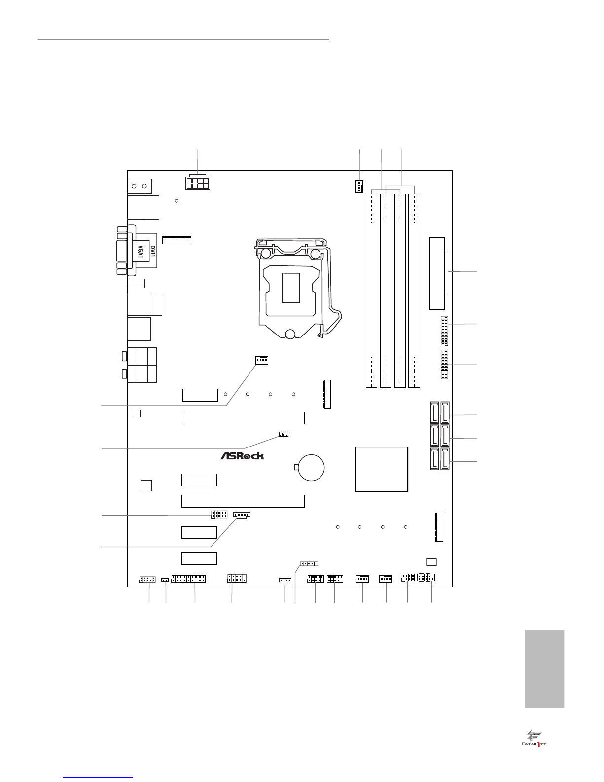
Fatal1ty H270 Performance Series
Motherboard Layout
Intel
H270
DDR 4_A2 (6 4 bit, 28 8-pin m odule )
DDR 4_A1 (6 4 bit, 28 8-pin m odule )
DDR 4_B2 (6 4 bit, 28 8-pin m odule )
DDR 4_B1 (6 4 bit, 28 8-pin m odule )
ATX12V1
ATXPWR1
LAN
PCIE2
Top:
RJ-45
USB 3.0
T: USB1
B: USB2
Top:
Central/Bass
Cente r:
REAR SP K
Top:
LINE IN
Cente r:
FRONT
Botto m:
Optic al
SPDIF
Botto m:
MIC IN
PCIE4
HDLED RESET
PLED PWRBTN
PANEL1
1
1
SPK_PLED1
1
HD_AUDIO1
SATA_2_3
SATA_0_1
PCIE1
RoHS
5
7
8
9
10
USB_3_4
1
15
USB_5_6
1
16 1422
26
24
23
HDMI1
SATA_4_5
1
4
3
2021 11
BIOS
ROM
USB 2. 0
T: USB1
B: USB 2
PS2
Keyb oard
/Mou se
CMOS
Battery
PCIE3
M2_ 2
M2_ 1
CT2
CT2
CT3
CT3
CT4
CT4
USB3_ 3_4
1
1213
CPU_FAN1
1
TPMS1
PCIE5
USB 3.0
T: USB3_TA_1
B: USB3_TC_1
CT1
CT1
Ultra M.2
PCIe Gen3x4
CHA_FAN2
CHA_FAN1
CHA_FAN3/W_PUMP
2
17
CLRMOS1
1
PCI Express 3.0
PCIE6
1
USB_7
1
CI1
T B1
1
T B2
1
M2_3
CT1
25
RGB_LED
1
18
FATALTY
1
AUDIO
CODEC
H270 Performance
6
USB3_ 5_6
1
COM1
1
19

English
2
No. Description
1 ATX 12V Power Connector (ATX12V1)
2 CPU Fan Connector (CPU_FAN1)
3 2 x 288-pin DDR4 DIMM Slots (DDR4_A1, DDR4_B1)
4 2 x 288-pin DDR4 DIMM Slots (DDR4_A2, DDR4_B2)
5 ATX Power Connector (ATXPWR1)
6 USB 3.0 Header (USB3_5_6)
7 USB 3.0 Header (USB3_3_4)
8 SATA3 Connectors (SATA_4_5)
9 SATA3 Connectors (SATA_2_3)
10 SATA3 Connectors (SATA_0_1)
11 System Panel Header (PANEL1)
12 Power LED and Speaker Header (SPK_PLED1)
13 Chassis Fan / Waterpump Fan Connector (CHA_FAN3/W_PUMP)
14 Chassis Fan Connector (CHA_FAN1)
15 USB 2.0 Header (USB_3_4)
16 USB 2.0 Header (USB_5_6)
17 USB 2.0 Header (USB_7)
18 AURA RGB LED Header (RGB_LED)
19 COM Port Header (COM1)
20 TPM Header (TPMS1)
21 Chassis Intrusion Header (CI1)
22 Front Panel Audio Header (HD_AUDIO1)
23 underbolt AIC Connector (TB1)
24 underbolt AIC Connector (TB2)
25 Clear CMOS Jumper (CLRMOS1)
26 Chassis Fan Connector (CHA_FAN2)
English
3
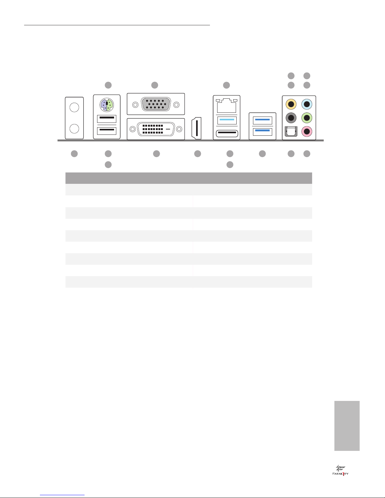
Fatal1ty H270 Performance Series
I/O Panel
No. Description No. Description
1 PS/2 Mouse/Keyboard Port (PS2_KB1) 10 USB 3.0 Ports (USB3_1_2)
2 D-Sub Port (VGA1) 11 USB 3.0 Type-A Port (USB3_TA_1)
3 LAN RJ-45 Port* 12 USB 3.0 Type-C Port (USB3_TC_1)
4 Central / Bass (Orange) 13 HDMI Port (HDMI1)
5 Rear Speaker (Black) 14 DVI-D Port (DVI1)
6 Line In (Light Blue) 15 Fatal1ty Mouse Port (USB_1)
7 Front Speaker (Lime)** 16 USB 2.0 Port (USB_2)
8 Microphone (Pink) 17 Antenna Ports
9 Optical SPDIF Out Port
1
8911
12
15
16
10131417
2 5
4
7
6
3
English
4
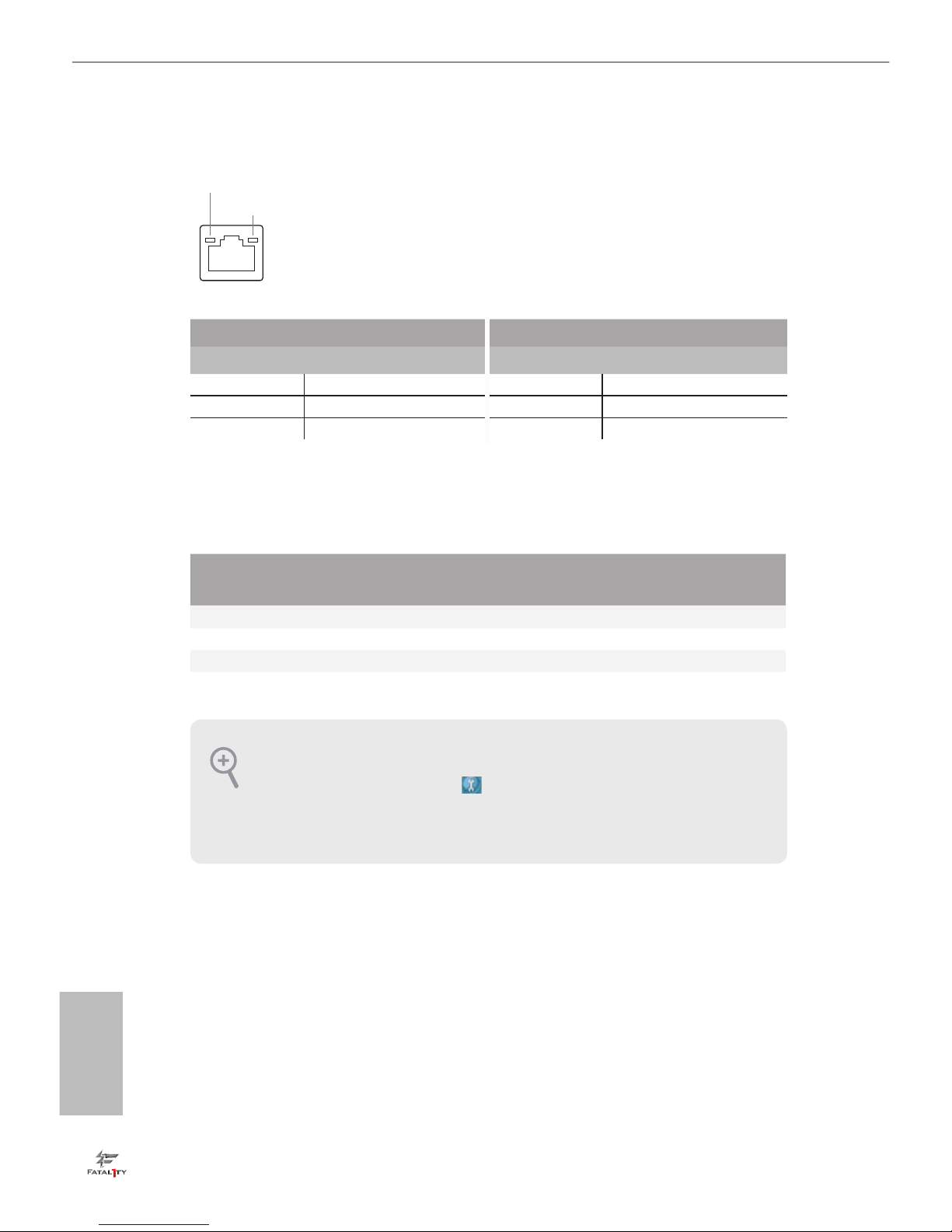
* ere are two LEDs on each LAN port. Please refer to the table below for the LAN port LED indications.
Activity / Link LED Speed LED
Status Description Status Description
O No Link O 10Mbps connection
Blinking Data Activity Orange 100Mbps connection
On Link Green 1Gbps connection
** If you use a 2-channel speaker, please connect the speaker’s plug into “Front Speaker Jack”. See the table below
for connection details in accordance with the type of speaker you use.
Audio Output
Channels
Front Speaker
(No. 7)
Rear Speaker
(No. 5)
Central / Bass
(No. 4)
Line In
(No. 6)
2 V -- -- --
4 V V -- --
6 V V V --
8 V V V V
To enable Multi-Streaming, you need to connect a front panel audio cable to the front
panel audio header. Aer restarting your computer, you will nd the “Mixer” tool on your
system. Please select “Mixer ToolBox” , click “Enable playback multi-streaming”, and
click “ok”. Choose “2CH”, “4CH”, “6CH”, or “8CH” and then you are allowed to select
“Realtek HDA Primary output” to use the Rear Speaker, Central/Bass, and Front Speaker,
or select “Realtek HDA Audio 2nd output” to use the front panel audio.
ACT/LINK LED
SPEED LED
LAN Por t
Chapter 1 Introduction
ank you for purchasing ASRock Fatal1ty H270 Performance Series motherboard,
a reliable motherboard produced under ASRock’s consistently stringent quality
control. It delivers excellent performance with robust design conforming to
ASRock’s commitment to quality and endurance.
1.1 Package Contents
•
ASRock Fatal1ty H270 Performance Series Motherboard (ATX Form Factor)
•
ASRock Fatal1ty H270 Performance Series Quick Installation Guide
•
ASRock Fatal1ty H270 Performance Series Support CD
•
1 x I/O Panel Shield
•
2 x Serial ATA (SATA) Data Cables (Optional)
•
3 x Screws for M.2 Socket (Optiona l)
English
5
Fatal1ty H270 Performance Series
Chapter 1 Introduction
ank you for purchasing ASRock Fatal1ty H270 Performance Series motherboard,
a reliable motherboard produced under ASRock’s consistently stringent quality
control. It delivers excellent performance with robust design conforming to
ASRock’s commitment to quality and endurance.
1.1 Package Contents
•
ASRock Fatal1ty H270 Performance Series Motherboard (ATX Form Factor)
•
ASRock Fatal1ty H270 Performance Series Quick Installation Guide
•
ASRock Fatal1ty H270 Performance Series Support CD
•
1 x I/O Panel Shield
•
2 x Serial ATA (SATA) Data Cables (Optional)
•
3 x Screws for M.2 Socket (Optiona l)
Because the motherboard specications and the BIOS soware might be updated, the
content of this documentation will be subject to change without notice. In case any modications of this documentation occur, the updated version will be available on ASRock’s
website without further notice. If you require technical support related to this motherboard, please visit our website for specic information about the model you are using. You
may nd the latest VGA cards and CPU support list on ASRock’s website as well. ASRock
website http://www.asrock.com.

English
6
1.2 Specications
Platform
•
ATX Form Factor
CPU
•
Supports 7th and 6th Generation Intel® CoreTM i7/i5/i3/
Pentium®/Celeron® Processors (Socket 1151)
•
Digi Power design
•
8 Power Phase design
•
Supports Intel® Turbo Boost 2.0 Technology
Chipset
•
Intel® H270
Memory
•
Dual Channel DDR4 Memory Technology
•
4 x DDR4 DIMM Slots
•
Supports DDR4 2400/2133 non-ECC, un-buered memory*
* 7th Gen Intel® CPU supports DDR4 up to 2400; 6th Gen Intel®
CPU supports DDR4 up to 2133.
•
Supports ECC UDIMM memory modules (operate in non-
ECC mode)
•
Max. capacity of system memory: 64GB
•
Supports Intel® Extreme Memory Prole (XMP) 2.0
•
15μ Gold Contact in DIMM Slots
Expansion
Slot
•
2 x PCI Express 3.0 x16 Slots (PCIE2: x16 mode; PCIE4: x4
mode)*
* Supports NVMe SSD as boot disks
•
4 x PCI Express 3.0 x1 Slots (Flexible PCIe)
* If PCIE5 or PCIE6 is occupied, PCIE4 will run at x2 mode.
•
Supports AMD Quad CrossFireXTM and CrossFireXTM
•
1 x M.2 Socket (Key E), supports type 2230 WiFi/BT module
* If M2_3 is occupied, PCIE3 will be disabled.
•
15μ Gold Contact in VGA PCIe Slot (PCIE2)
Graphics
•
Intel® HD Graphics Built-in Visuals and the VGA outputs
can be supported only with processors which are GPU
integrated.
•
Supports Intel® HD Graphics Built-in Visuals : Intel® Quick
Sync Video with AVC, MVC (S3D) and MPEG-2 Full
HW Encode1, Intel® InTruTM 3D, Intel® Clear Video HD
Technology, Intel® InsiderTM, Intel® HD Graphics

English
7
Fatal1ty H270 Performance Series
•
Gen9 LP, DX11.3, DX12
•
HWAEncode/Decode: VP8, HEVC 8b, VP9, HEVC 10b (For
7th Gen Intel® CPU)
•
HWA Encode/Decode: VP8 , HEVC 8b; GPU/SWEncode/
Decode: VP9, HEVC 10b (For 6th Gen Intel® CPU)
•
Max. shared memory 1024MB
* e size of maximum shared memory may vary from dierent
operating systems.
•
ree graphics output options: D-Sub, DVI-D and HDMI
•
Supports Triple Monitor
•
Supports HDMI with max. resolution up to 4K x 2K
(4096x2160) @ 24Hz / (3840x2160) @ 30Hz
•
Supports DVI-D with max. resolution up to 1920x1200 @
60Hz
•
Supports D-Sub with max. resolution up to 1920x1200 @
60Hz
•
Supports Auto Lip Sync, Deep Color (12bpc), xvYCC and
HBR (High Bit Rate Audio) with HDMI Port (Compliant
HDMI monitor is required)
•
Supports HDCP with DVI-D and HDMI Ports
•
Supports Full HD 1080p Blu-ray (BD) playback with DVI-D
and HDMI Ports
Audio
•
7.1 CH HD Audio with Content Protection (Realtek
ALC1220 Audio Codec)
•
Premium Blu-ray Audio support
•
Supports Surge Protection (ASRock Full Spike Protection)
•
Nichicon Fine Gold Series Audio Caps
•
120dB SNR DAC with Dierential Amplier
•
TI® NE5532 Premium Headset Amplier for Front Panel
Audio Connector (Supports up to 600 Ohm headsets)
•
Pure Power-In
•
Direct Drive Technology
•
PCB Isolate Shielding
•
Impedance Sensing on Front Out port
•
Individual PCB Layers for R/L Audio Channel
•
AURA RGB LED
•
Gold Audio Jacks
•
15μ Gold Audio Connector
•
Supports Creative SoundBlaster Cinema3

English
8
LAN
•
Gigabit LAN 10/100/1000 Mb/s
•
Giga PHY Intel® I219V
•
Supports Wake-On-LAN
•
Supports Lightning/ESD Protection (ASRock Full Spike
Protection)
•
Supports Energy Ecient Ethernet 802.3az
•
Supports PXE
Rear Panel
I/O
•
2 x Antenna Ports
•
1 x PS/2 Mouse/Keyboard Port
•
1 x D-Sub Port
•
1 x DVI-D Port
•
1 x HDMI Port
•
1 x Optical SPDIF Out Port
•
1 x USB 2.0 Port (Supports ESD Protection (ASRock Full
Spike Protection))
•
1 x Fatal1ty Mouse Port (USB 2.0) (Supports ESD Protection
(ASRock Full Spike Protection))
•
3 x USB 3.0 Type-A Ports (Supports ESD Protection (ASRock
Full Spike Protection))
•
1 x USB 3.0 Type-C Port (Supports ESD Protection (ASRock
Full Spike Protection))
•
1 x RJ-45 LAN Port with LED (ACT/LINK LED and SPEED
LED)
•
HD Audio Jacks: Rear Speaker / Central / Bass / Line in /
Front Speaker / Microphone (Gold Audio Jacks)
Storage
•
6 x SATA3 6.0 Gb/s Connectors, support RAID (RAID 0,
RAID 1, RAID 5, RAID 10, Intel Rapid Storage Technology
15 and Intel Smart Response Technology), NCQ, AHCI and
Hot Plug*
* If M2_1 is occupied by a SATA-type M.2 device, SATA_5 will
be disabled.
* If M2_2 is occupied by a SATA-type M.2 device, SATA_0 will
be disabled.
•
2 x Ultra M.2 Sockets, support type 2230/2242/2260/2280
M.2 SATA3 6.0 Gb/s module and M.2 PCI Express module
up to Gen3 x4 (32 Gb/s)**
** Supports Intel® OptaneTM Technology
** Supports NVMe SSD as boot disks
** Supports ASRock U.2 Kit

English
9
Fatal1ty H270 Performance Series
Connector
•
1 x COM Port Header
•
1 x TPM Header
•
1 x Chassis Intrusion Header
•
1 x Power LED and Speaker Header
•
1 x CPU Fan Connector (4-pin)
* e CPU Fan Connector supports the CPU fan of maximum
1A (12W) fan power.
•
2 x Chassis Fan Connectors (4-pin) (Smart Fan Speed
Control)
•
1 x Chassis Optional/Water Pump Fan Connector (4-pin)
(Smart Fan Speed Control)
* e Chassis Optional/Water Pump Fan supports the water
cooler fan of maximum 1.5A (18W) fan power.
* CHA_FAN2 can auto detect if 3-pin or 4-pin fan is in use.
•
1 x 24 pin ATX Power Connector (Hi-Density Power
Connector)
•
1 x 8 pin 12V Power Connector (Hi-Density Power
Connector)
•
1 x Front Panel Audio Connector (15μ Gold Audio Connec-
tor)
•
1 x underbolt AIC Connector (5-pin)
•
1 x underbolt AIC Connector (10-pin)
* Only one underbolt AIC Card is supported.
•
3 x USB 2.0 Headers (Support 5 USB 2.0 ports) (Supports
ESD Protection (ASRock Full Spike Protection))
•
2 x USB 3.0 Headers (Support 4 USB 3.0 ports) (Supports
ESD Protection (ASRock Full Spike Protection))
BIOS
Feature
•
AMI UEFI Legal BIOS with multilingual GUI support
•
ACPI 6.0 Compliant wake up events
•
SMBIOS 2.7 Support
•
CPU, GT_CPU, DRAM, VPPM, PCH 1.0V, VCCIO, VCCST,
VCCSA, VCCPLL Voltage Multi-adjustment
Hardware
Monitor
•
Temperature Sensing: CPU, Chassis, Chassis Optional/
Water Pump Fans
•
Fan Tachometer: CPU, Chassis, Chassis Optional/Water
Pump Fans
•
Quiet Fan (Auto adjust chassis fan speed by CPU tempera-
ture): CPU, Chassis, Chassis Optional/Water Pump Fans
English
10
•
Fan Multi-Speed Control: CPU, Chassis, Chassis Optional/
Water Pump Fans
•
CASE OPEN detection
•
Voltage monitoring: +12V, +5V, +3.3V, CPU Vcore, DRAM,
VPPM, PCH 1.0V, VCCSA, VCCST
OS
•
Microso® Windows® 10 64-bit (For 7th Gen Intel® CPU)
•
Microso® Windows® 10 64-bit / 8.1 64-bit / 7 32-bit / 7 64-
bit (For 6th Gen Intel® CPU)
* To install Windows® 7 OS, a modied installation disk with
xHCI drivers packed into the ISO le is required. Please refer to
page 168 for more detailed instructions.
* For the updated Windows® 10 driver, please visit ASRock’s
website for details: http://www.asrock.com
Certications
•
FCC, CE, WHQL
•
ErP/EuP ready (ErP/EuP ready power supply is required)
Please realize that there is a certain risk involved with overclocking, including adjusting
the setting in the BIOS, applying Untied Overclocking Technology, or using third-party
overclocking tools. Overclocking may aect your system’s stability, or even cause damage to
the components and devices of your system. It should be done at your own risk and expense.
We are not responsible for possible damage caused by overclocking.
* For detailed product information, please visit our website: http://www.asrock.com

English
11
Fatal1ty H270 Performance Series
is is an ATX form factor motherboard. Before you install the motherboard, study
the conguration of your chassis to ensure that the motherboard ts into it.
Pre-installation Precautions
Take note of the following precautions before you install motherboard components
or change any motherboard settings.
•
Make sure to unplug the power cord before installing or removing the motherboard
components. Failure to do so may cause physical injuries and damages to motherboard
components.
•
In order to avoid damage from static electricity to the motherboard’s components,
NEVER place your motherboard directly on a carpet. Also remember to use a grounded
wrist strap or touch a safety grounded object before you handle the components.
•
Hold components by the edges and do not touch the ICs.
•
Whenever you uninstall any components, place them on a grounded anti-static pad or
in the bag that comes with the components.
•
When placing screws to secure the motherboard to the chassis, please do not overtighten the screws! Doing so may damage the motherboard.
Chapter 2 Installation
English
12
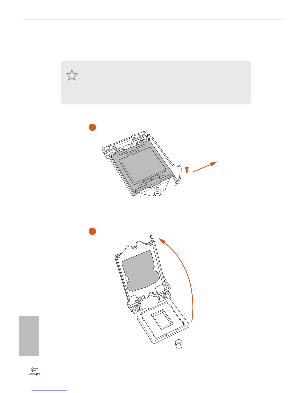
2.1 Installing the CPU
1. Before you insert the 1151-Pin CPU into the socket, please check if the PnP cap is on the
socket, if the CPU surface is unclean, or if there are any bent pins in the socket. Do not
force to insert the CPU into the socket if above situation is found. Otherwise, the CPU
will be seriously damaged.
2. Unplug all power cables before installing the CPU.
1
2
A
B
English
13
Fatal1ty H270 Performance Series
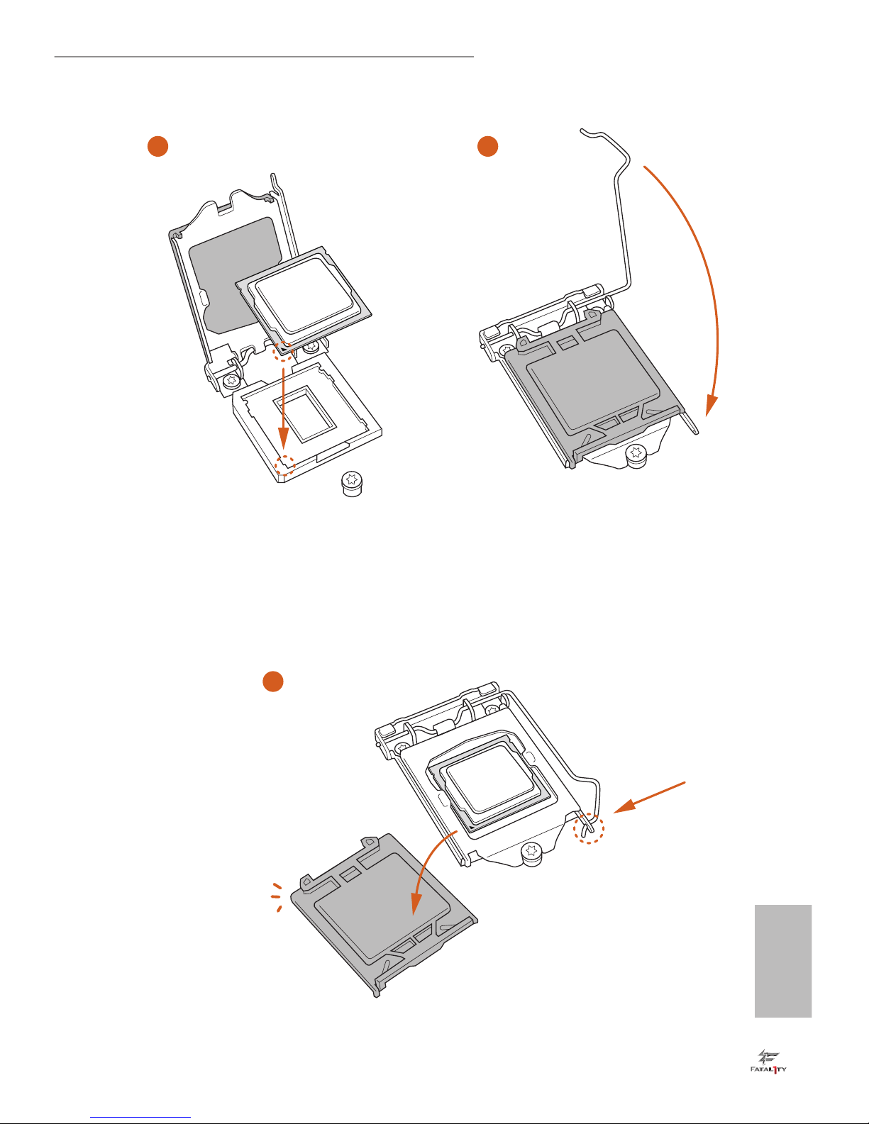
4
5
3
English
14
Please save and replace the cover if the processor is removed. e cover must be placed if
you wish to return the motherboard for aer service.
English
15
Fatal1ty H270 Performance Series
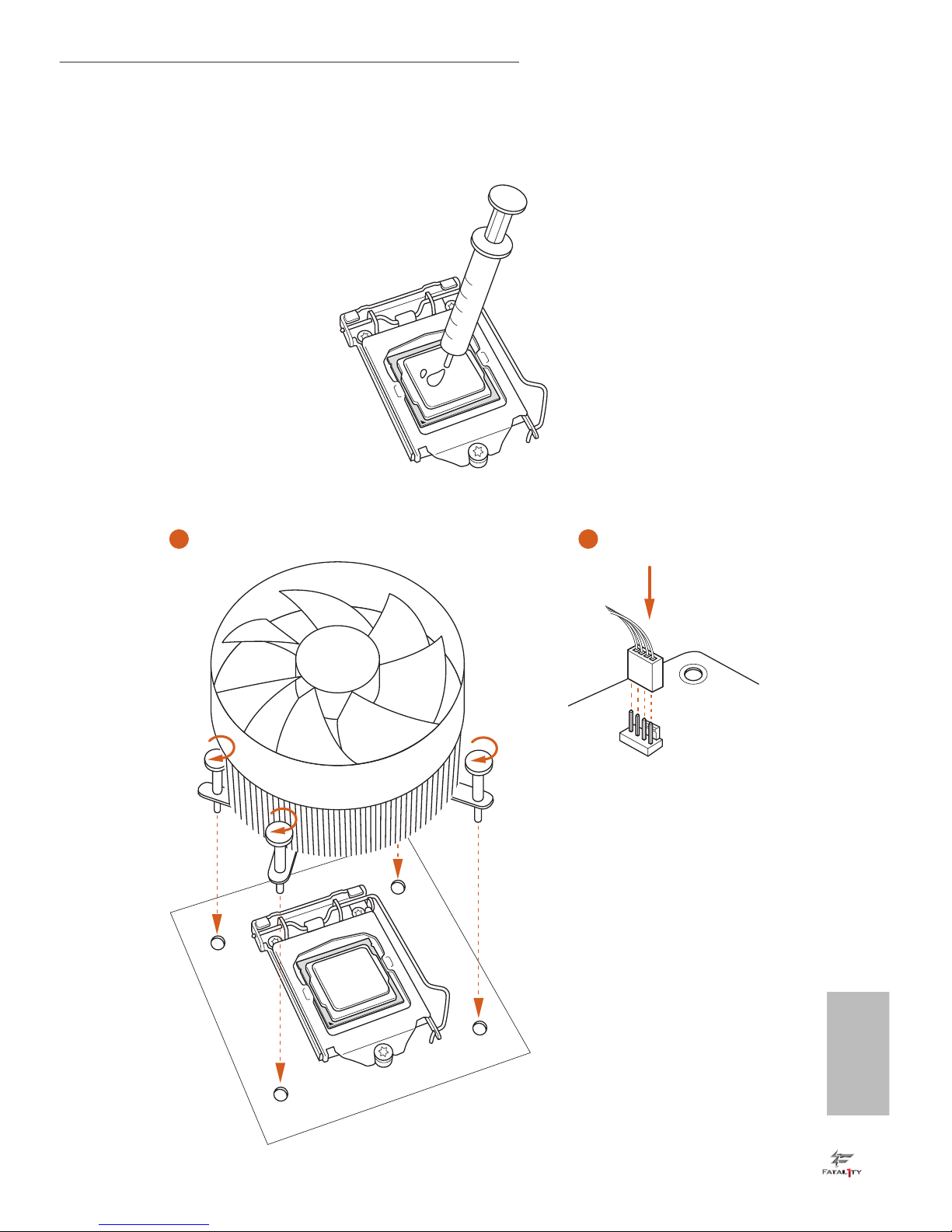
2.2 Installing the CPU Fan and Heatsink
1 2
CPU_
FAN
English
16
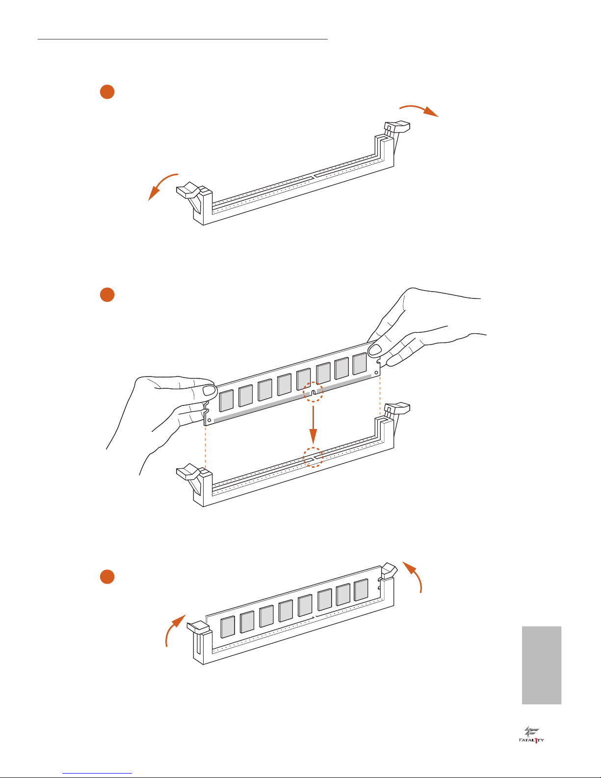
2.3 Installing Memory Modules (DIMM)
is motherboard provides four 288-pin DDR4 (Double Data Rate 4) DIMM slots,
and supports Dual Channel Memory Technology.
Dual Channel Memory Conguration
e DIMM only ts in one correct orientation. It will cause permanent damage to the
motherboard and the DIMM if you force the DIMM into the slot at incorrect orientation.
Priority DDR4_A1 DDR4_A2 DDR4_B1 DDR4_B2
1 Populated Populated
2 Populated Populated
3 Populated Populated Populated Populated
1. For dual channel conguration, you always need to install identical (the same brand,
speed, size and chip-type) DDR4 DIMM pairs.
2. It is unable to activate Dual Channel Memory Technology with only one or three memory
module installed.
3. It is not allowed to install a DDR, DDR2 or DDR3 memory module into a DDR4 slot;
otherwise, this motherboard and DIMM may be damaged.
English
17
Fatal1ty H270 Performance Series
1
2
3
English
18
2.4 Expansion Slots (PCI Express Slots)
ere are 6 PCI Express slots on the motherboard.
PCIe slots:
PCIE1 (PCIe 3.0 x1 slot) is used for PCI Express x1 lane width cards.
PCIE2 (PCIe 3.0 x16 slot) is used for PCI Express x16 lane width graphics cards.
PCIE3 (PCIe 3.0 x1 slot) is used for PCI Express x1 lane width cards.
PCIE4 (PCIe 3.0 x16 slot) is used for PCI Express x4 lane width graphics cards.
PCIE5 (PCIe 3.0 x1 slot) is used for PCI Express x1 lane width cards.
PCIE6 (PCIe 3.0 x1 slot) is used for PCI Express x1 lane width cards.
* If PCIE5 or PCIE6 is occupied, PCIE4 will run at x2 mode.
* If M2_3 is occupied, PCIE3 will be disabled.
PCIe Slot Congurations
For a better thermal environment, please connect a chassis fan to the motherboard’s chassis
fan connector (CHA_FAN1 or CHA_FAN2) when using multiple graphics cards.
Before installing an expansion card, please make sure that the power supply is switched o
or the power cord is unplugged. Please read the documentation of the expansion card and
make necessary hardware settings for the card before you start the installation.
PCIE2 PCIE4
Single Graphics Card x16 N/A
Two Graphics Cards in
CrossFireXTM Mode
x16 x4
English
19
Fatal1ty H270 Performance Series
2.5 Jumpers Setup
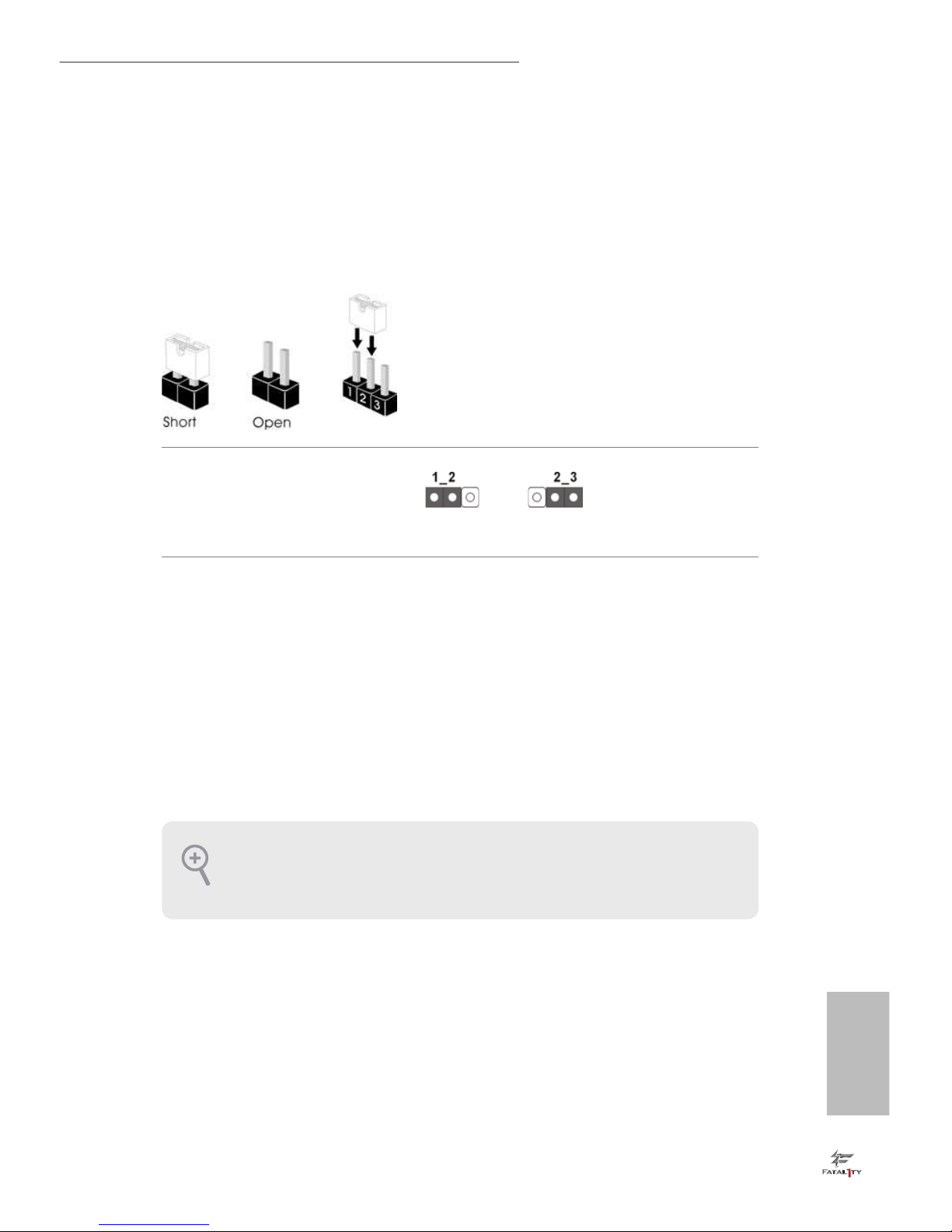
e illustration shows how jumpers are setup. When the jumper cap is placed on
the pins, the jumper is “Short”. If no jumper cap is placed on the pins, the jumper
is “Open”. e illustration shows a 3-pin jumper whose pin1 and pin2 are “Short”
when a jumper cap is placed on these 2 pins.
Clear CMOS Jumper
(CLRMOS1)
(see p.1, No. 25)
CLRMOS1 allows you to clear the data in CMOS. To clear and reset the system
parameters to default setup, please turn o the computer and unplug the power
cord from the power supply. Aer waiting for 15 seconds, use a jumper cap to
short pin2 and pin3 on CLRMOS1 for 5 seconds. However, please do not clear the
CMOS right aer you update the BIOS. If you need to clear the CMOS when you
just nish updating the BIOS, you must boot up the system rst, and then shut it
down before you do the clear-CMOS action. Please be noted that the password,
date, time, and user default prole will be cleared only if the CMOS battery is
removed.
Clear CMOSDefault
If you clear the CMOS, the case open may be detected. Please adjust the BIOS option “Clear
Status” to clear the record of previous chassis intrusion status.
English
20
2.6 Onboard Headers and Connectors
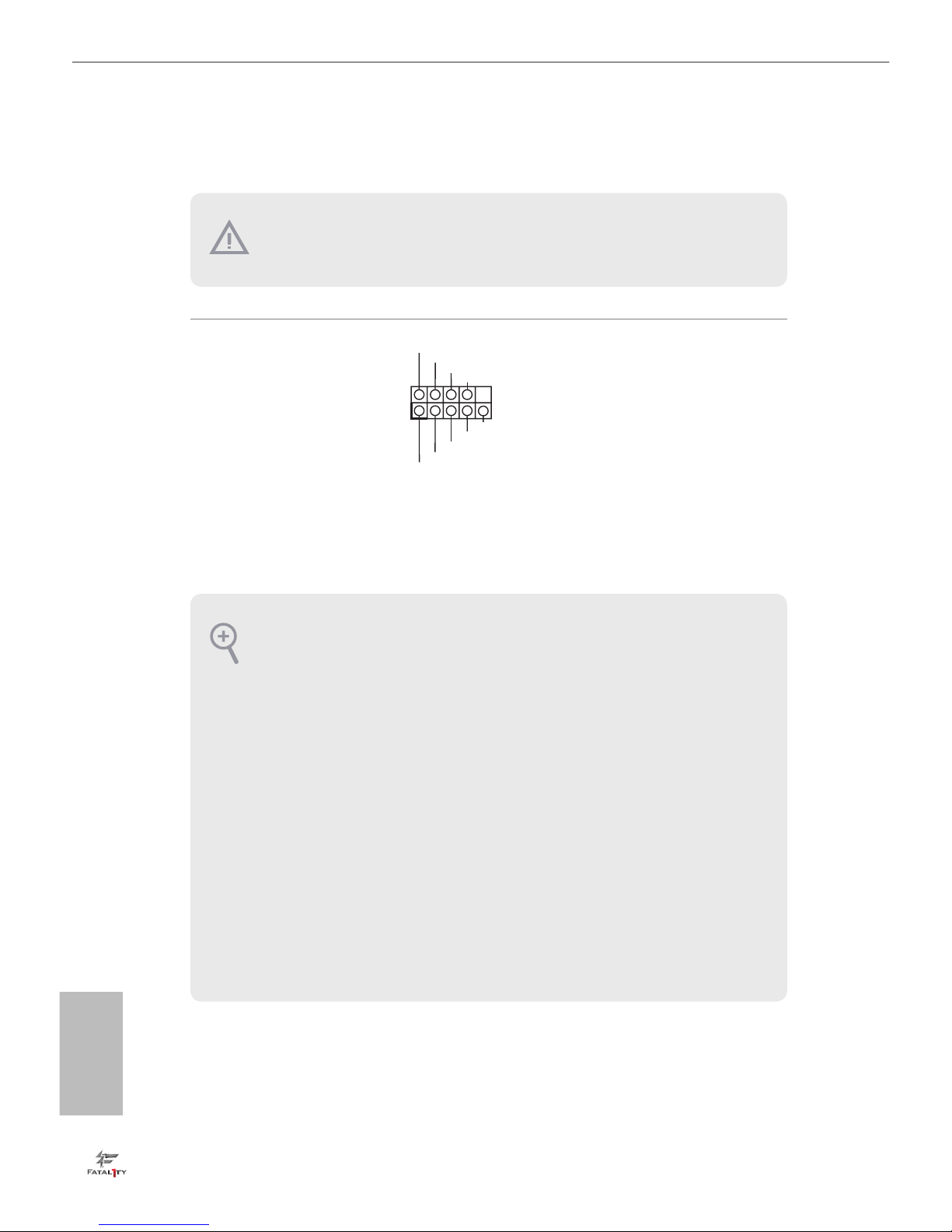
System Panel Header
(9-pin PANEL1)
(see p.1, No. 11)
Connect the power
switch, reset switch and
system status indicator on
the chassis to this header
according to the pin
assignments below. Note
the positive and negative
pins before connecting
the cables.
GND
RESET#
PWRBTN#
PLED-
PLED+
GND
HDLED-
HDLED+
1
GND
PWRBTN (Power Switch):
Connect to the power switch on the chassis front panel. You may congure the way to turn
o your system using the power switch.
RESET (Reset Switch):
Connect to the reset switch on the chassis front panel. Press the reset switch to restart the
computer if the computer freezes and fails to perform a normal restart.
PLED (System Power LED):
Connect to the power status indicator on the chassis front panel. e LED is on when the
system is operating. e LED keeps blinking when the system is in S1/S3 sleep state. e
LED is o when the system is in S4 sleep state or powered o (S5).
HDLED (Hard Drive Activity LED):
Connect to the hard drive activity LED on the chassis front panel. e LED is on when the
hard drive is reading or writing data.
e front panel design may dier by chassis. A front panel module mainly consists of power
switch, reset switch, power LED, hard drive activity LED, speaker and etc. When connecting your chassis front panel module to this header, make sure the wire assignments and the
pin assignments are matched correctly.
Onboard headers and connectors are NOT jumpers. Do NOT place jumper caps over these
headers and connectors. Placing jumper caps over the headers and connectors will cause
permanent damage to the motherboard.
English
21
Fatal1ty H270 Performance Series
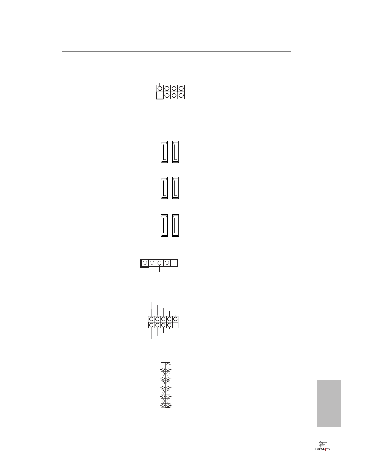
Power LED and Speaker
Header
(7-pin SPK_PLED1)
(see p.1, No. 12)
Please connect the
chassis power LED and
the chassis speaker to this
header.
Serial ATA3 Connectors
(SATA_4_5:
see p.1, No. 8)
(SATA_2_3:
see p.1, No. 9)
(SATA_0_1:
see p.1, No. 10)
ese six SATA3
connectors support SATA
data cables for internal
storage devices with up to
6.0 Gb/s data transfer rate.
* If M2_1 is occupied by
a SATA-type M.2 device,
SATA_5 will be disabled.
* If M2_2 is occupied by
a SATA-type M.2 device,
SATA_0 will be disabled.
USB 2.0 Headers
(5-pin USB_7)
(see p.1, No. 17)
(9-pin USB_3_4)
(see p.1, No. 15)
(9-pin USB_5_6)
(see p.1, No. 16)
ere are three USB
2.0 headers on this
motherboard.
USB 3.0 Headers
(19-pin USB3_3_4)
(see p.1, No. 7)
(19-pin USB3_5_6)
(see p.1, No. 6)
Besides four USB 3.0 ports
on the I/O panel, there
are two headers on this
motherboard. Each USB
3.0 header can support
two ports.
1
+5V
DUMMY
PLED+
PLED+
PLED-
DUMMY
SPEAKER
SATA_2SATA_0
SATA_4
SATA_3SATA_1
SATA_5
DUMMY
GND
GND
P+
P-
USB_PWR
P+
P-
USB_PWR
1
1
IntA_PB_D+
Dummy
IntA_PB_D-
GND
IntA_PB_SSTX+
GND
IntA_PB_SSTX-
IntA_PB_SSRX+
IntA_PB_SSRX-
VbusVbus
Vbus
IntA_PA_SSRX-
IntA_PA_SSRX+
GND
IntA_PA_SSTX-
IntA_PA_SSTX+
GND
IntA_PA_D-
IntA_PA_D+
1
USB_PWR
P-
P+
GND
English
22
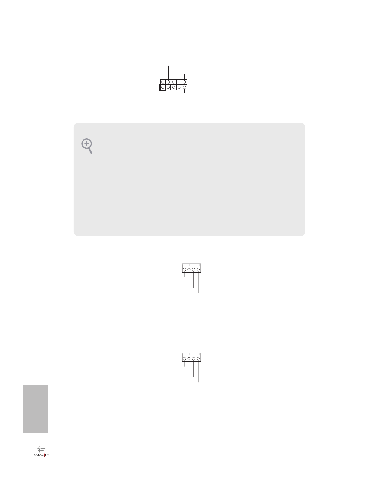
Front Panel Audio Header
(9-pin HD_AUDIO1)
(see p.1, No. 22)
is header is for
connecting audio devices
to the front audio panel.
Chassis Fan Connectors
(4-pin CHA_FAN1)
(see p.1, No. 14)
(4-pin CHA_FAN2)
(see p.1, No. 26)
Please connect fan cables
to the fan connectors and
match the black wire to
the ground pin.
Chassis Optional/Water
Pump Fan Connector
(4-pin CHA_FAN3/W_
PUMP)
(see p.1, No. 13)
is motherboard
provides two 4-Pin water
cooling
chassis
fan
connectors. If you plan to
connect a 3-Pin
chassis
water cooler fan, please
connect it to Pin 1-3.
J_SENSE
OUT2_L
1
MIC_RET
PRESENCE#
GND
OUT2_R
MIC2_R
MIC2_L
OUT_RET
1. High Denition Audio supports Jack Sensing, but the panel wire on the chassis must support HDA to function correctly. Please follow the instructions in our manual and chassis
manual to install your system.
2. If you use an AC’97 audio panel, please install it to the front panel audio header by the
steps below:
A. Connect Mic_IN (MIC) to MIC2_L.
B. Connect Audio_R (RIN) to OUT2_R and Audio_ L (LIN) to OUT2_L.
C. Connect Ground (GND) to Ground (GND).
D. MIC_ RET and OUT_RET are for the HD audio panel only. You don’t need to connect
them for the AC’97 audio panel.
E. To activate the front mic, go to the “FrontMic” Tab in the Realtek Control panel and
adjust “Recording Volume”.
GN
D
FAN_VOLTAGE
CHA_FAN_SPEED
F
AN_SPEED_CONTROL
4 3 2 1
GN
D
FAN_VOLTAGE
CHA_FAN_SPEED
F
AN_SPEED_CONTROL
4 3 2 1
English
23
Fatal1ty H270 Performance Series
CPU Fan Connector
(4-pin CPU_FAN1)
(see p.1, No. 2)
is motherboard provides a 4-Pin CPU fan
(Quiet Fan) connector.
If you plan to connect a
3-Pin CPU fan, please
connect it to Pin 1-3.
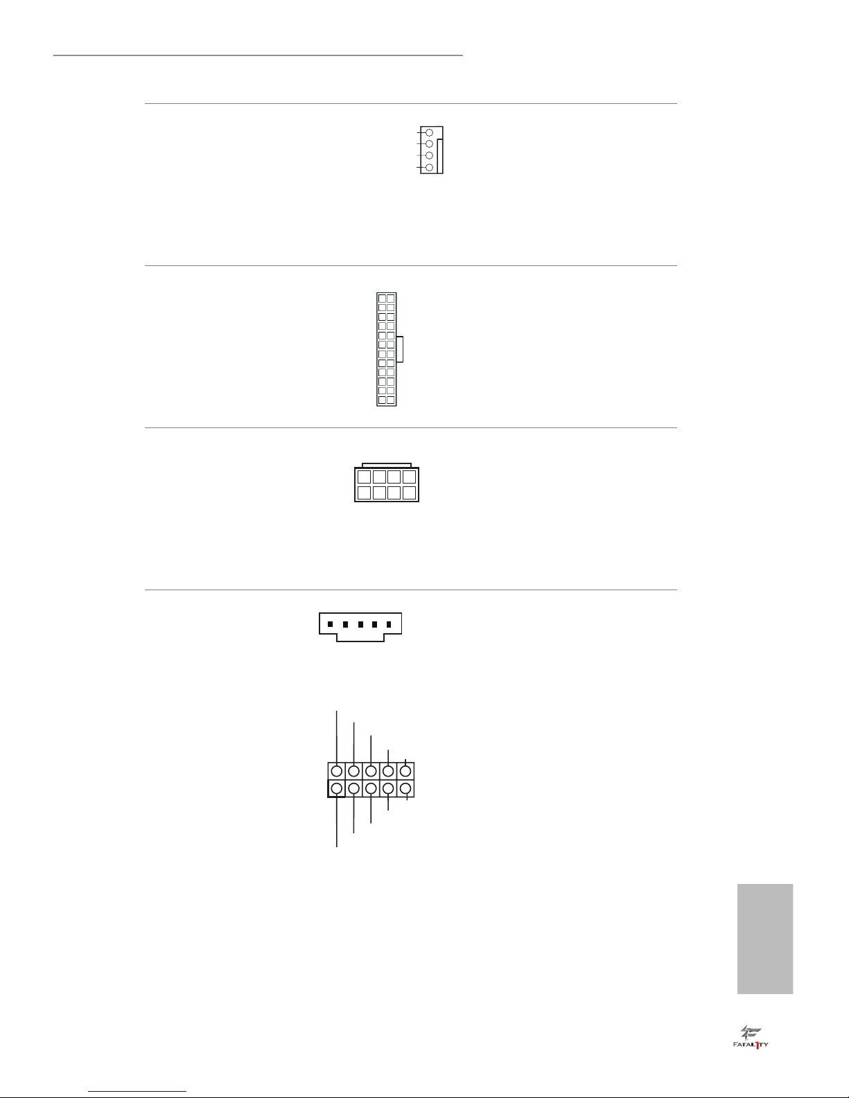
ATX Power Connector
(24-pin ATXPWR1)
(see p.1, No. 5)
is motherboard provides a 24-pin ATX power
connector. To use a 20-pin
ATX power supply, please
plug it along Pin 1 and Pin
13.
ATX 12V Power
Connector
(8-pin ATX12V1)
(see p.1, No. 1)
is motherboard provides an 8-pin ATX 12V
power connector. To use a
4-pin ATX power supply,
please plug it along Pin 1
and Pin 5.
underbolt AIC
Connectors
(5-pi n T B1)
(see p.1, No. 23)
(10-pin TB2)
(see p.1, No. 24)
Please connect a underbolt™
add-in card (AIC) to the
underbolt AIC connector via
the GPIO cable.
*Please install the underbolt™
AIC card to PCIE4 (default
slot).
*Only one underbolt AIC
Card is supported on this
motherboard.
12
1
24
13
4
1
8
5
I2C_DATA
GND
SLP_S3#
FRC_PWR
DUMMY
PLUG_EVENT
SLP_S4#
IRQ
GND
I2C_CLOCK
1
FAN_VOLTAGE
GND
FAN_SPEED
FA
N_SPEED_CONTROL
1
2
3
4
English
24
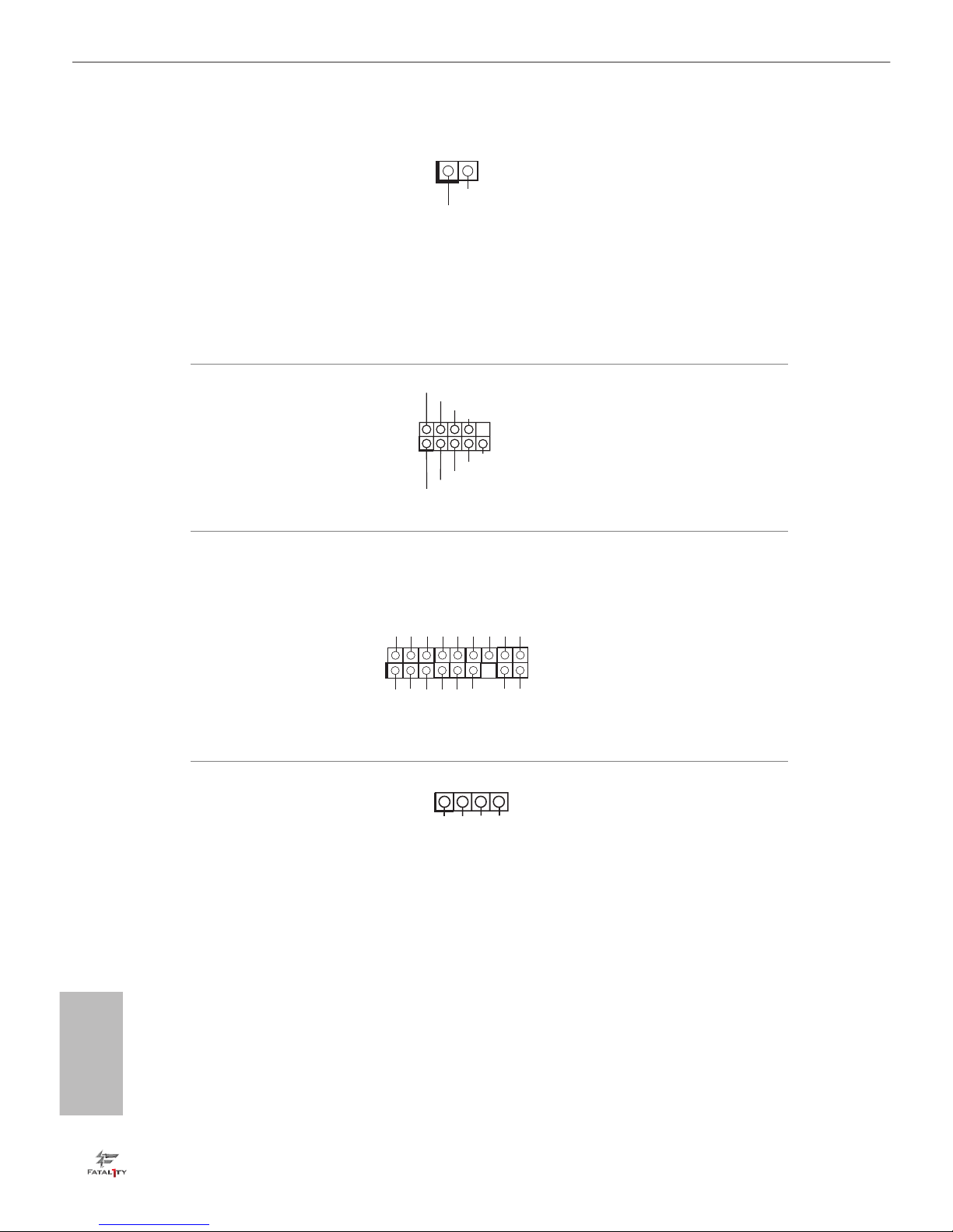
Chassis Intrusion Header
(2-pi n CI1)
(see p.1, No. 21)
is motherboard supports CASE OPEN
detection feature that
detects if the chassis cover
has been removed. is
feature requires a chassis
with chassis intrusion
detection design.
Serial Port Header
(9-pi n COM1)
(see p.1, No. 19)
is COM1 header
supports a serial port
module.
TPM Header
(17-pin TPMS1)
(see p.1, No. 20)
is connector supports Trusted
Platform Module (TPM) system,
which can securely store keys,
digital certicates, passwords,
and data. A TPM system also
helps enhance network security,
protects digital identities, and
ensures platform integrity.
AURA RGB LED Header
(4-pin RGB_LED)
(see p.1, No. 18)
AURA RGB header is used to
connect RGB LED extension
cable which allows users to
choose from various LED lighting eects.
1
GN D
SMB _D ATA _M AIN
LAD 2
LAD 1
GN D
S_P WR DWN #
SER IR Q #
GN
D
P CIC LK
P CIR ST #
LAD 3
+3 V
LAD 0
+3 VS B
GN D
FRA M E
SMB _C LK_ MA IN
1
Signal
GN
D
12V GRB
1
CCTS#1
RRTS#1
DDSR#1
DDTR#1
RRXD1
GND
TTXD1
DDCD#1
1
RRI#1
English
25
Fatal1ty H270 Performance Series
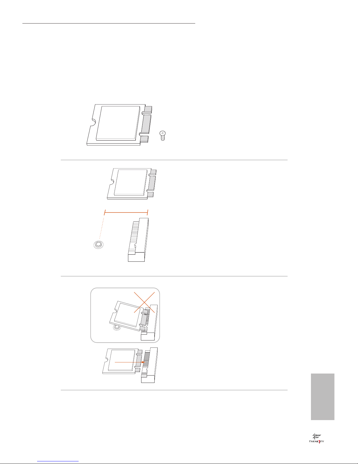
2.7 M.2 WiFi/BT Module Installation Guide
e M.2 Socket (Key E) supports type 2230 WiFi/BT module.
Installing the WiFi/BT module
Step 1
Prepare a type 2230 WiFi/BT module
and the screw.
A
Module Type: Type2230
PCB Length: 3cm
Step 2
Find the nut location to be used.
A
Step 3
Align and gently insert the WiFi/BT
module into the M.2 slot. Please be
aware that the module only ts in one
orientation.
English
26
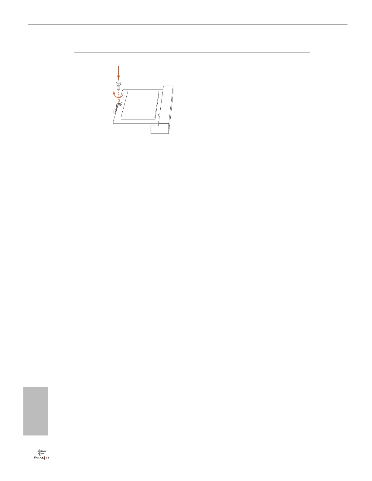
A
Step 4
Tighten the screw with a screwdriver
to secure the module into place.
Please do not overtighten the screw as
this might damage the module.
 Loading...