

Page 1

Fatal1ty Story
Who knew that at age 19, I would be a World Champion PC gamer. When I was 13, I
actually played competitive billiards in professional tournaments and won four or five
games off guys who played at the highest level. I actually thought of making a career
of it, but at that young age situations change rapidly. Because I’ve been blessed with
great hand-eye coordination and a grasp of mathematics (an important element in video
gaming) I gravitated to that activity.
GOING PRO
I started professional gaming in 1999 when I entered the CPL (Cyberathlete Professional
League) tournament in Dallas and won $4,000 for coming in third place. Emerging as one
of the top players in the United States, a company interested in sponsoring me fl ew me
to Sweden to compete against the top 12 players in the world. I won 18 straight games,
lost none, and took fi rst place, becoming the number one ranked Quake III player in the
world in the process. Two months later I followed that success by traveling to Dallas
and defending my title as the world’s best Quake III player, winning the $40,000 grand
prize. From there I entered competitions all over the world, including Singapore, Korea,
Germany, Australia, Holland and Brazil in addition to Los Angeles, New York and St.
Louis.
WINNING STREAK
I was excited to showcase my true gaming skills when defending my title as CPL
Champion of the year at the CPL Winter 2001 because I would be competing in a totally
different first person shooter (fps) game, Alien vs. Predator II. I won that competition
and walked away with a new car. The next year I won the same title playing Unreal
Tournament 2003, becoming the only three-time CPL champion of the year. And I did it
playing a different game each year, something no one else has ever done and a feat of
which I am extremely proud.
At QuakeCon 2002, I faced off against my rival ZeRo4 in one of the most highly
anticipated matches of the year, winning in a 14 to (-1) killer victory. Competing at
Quakecon 2004, I became the World’s 1st Doom3 Champion by defeating Daler in a
series of very challenging matches and earning $25,000 for the victory.
Since then Fatal1ty has traveled the globe to compete against the best in the world,
winning prizes and acclaim, including the 2005 CPL World Tour Championship in New
York City for a $150,000 fi rst place triumph. In August 2007, Johnathan was awarded the
fi rst ever Lifetime Achievement Award in the four year history of the eSports-Award for
“showing exceptional sportsmanship, taking part in shaping eSports into what it is today
and for being the prime representative of this young sport. He has become the fi gurehead
for eSports worldwide”.
Fatal1ty Z77 Professional Series Motherboard
English
1
Page 2

LIVIN’ LARGE
Since my fi rst big tournament wins, I have been a “Professional Cyberathlete”, traveling
the world and livin’ large with lots of International media coverage on outlets such as
MTV, ESPN and a 60 Minutes segment on CBS to name only a few. It's unreal - it's crazy.
I’m living a dream by playing video games for a living. I’ve always been athletic and
took sports like hockey and football very seriously, working out and training hard. This
discipline helps me become a better gamer and my drive to be the best has opened the
doors necessary to become a professional.
A DREAM
Now, another dream is being realized – building the ultimate gaming computer, made
up of the best parts under my own brand. Quality hardware makes a huge difference in
competitions…a couple more frames per second and everything gets really nice. It’s all
about getting the computer processing faster and allowing more fl uid movement around
the maps.
My vision for Fatal1ty hardware is to allow gamers to focus on the game without worrying
about their equipment, something I’ve preached since I began competing. I don’t want to
worry about my equipment. I want to be there – over and done with - so I can focus on the
game. I want it to be the fastest and most stable computer equipment on the face of the
planet, so quality is what Fatal1ty Brand products represent.
Johnathan “Fatal1ty” Wendel
English
The Fatal1ty name, Fatal1ty logos and the Fatal1ty likeness are registered trademarks of
Fatal1ty, Inc., and are used under license. © 2011 Fatal1ty, Inc. All rights reserved. All other
trademarks are the property of their respective owners.
2
Fatal1ty Z77 Professional Series Motherboard
Page 3

Copyright Notice:
No part of this manual may be reproduced, transcribed, transmitted, or translated in
any language, in any form or by any means, except duplication of documentation by
the purchaser for backup purpose.
Products and corporate names appearing in this manual may or may not be registered trademarks or copyrights of their respective companies, and are used only for
identifi cation or explanation and to the owners’ benefi t, without intent to infringe.
Disclaimer:
Specifi cations and information contained in this manual are furnished for informa-
tional use only and subject to change without notice, and should not be constructed
as a commitment by us. We assumes no responsibility for any errors or omissions
that may appear in this manual.
With respect to the contents of this manual, We do not provide warranty of any kind,
either expressed or implied, including but not limited to the implied warranties or
conditions of merchantability or fi tness for a particular purpose.
In no event shall we, its directors, offi cers, employees, or agents be liable for any
indirect, special, incidental, or consequential damages (including damages for loss
of profi ts, loss of business, loss of data, interruption of business and the like), even
if we have been advised of the possibility of such damages arising from any defect
or error in the manual or product.
This device complies with Part 15 of the FCC Rules. Operation is subject to the following two conditions:
(1) this device may not cause harmful interference, and
(2) this device must accept any interference received, including interference that
may cause undesired operation.
CALIFORNIA, USA ONLY
The Lithium battery adopted on this motherboard contains Perchlorate, a toxic
substance controlled in Perchlorate Best Management Practices (BMP) regulations
passed by the California Legislature. When you discard the Lithium battery in California, USA, please follow the related regulations in advance.
“Perchlorate Material-special handling may apply, see
www.dtsc.ca.gov/hazardouswaste/perchlorate”
The Fatal1ty name, Fatal1ty logos and the Fatal1ty likeness are registered trademarks of Fatal1ty, Inc., and are used under license. © 2010 Fatal1ty, Inc. All rights
reserved. All other trademarks are the property of their respective owners.
Fatal1ty website: www.fatal1ty.com
Published December 2011
Fatal1ty Z77 Professional Series Motherboard
English
3
Page 4
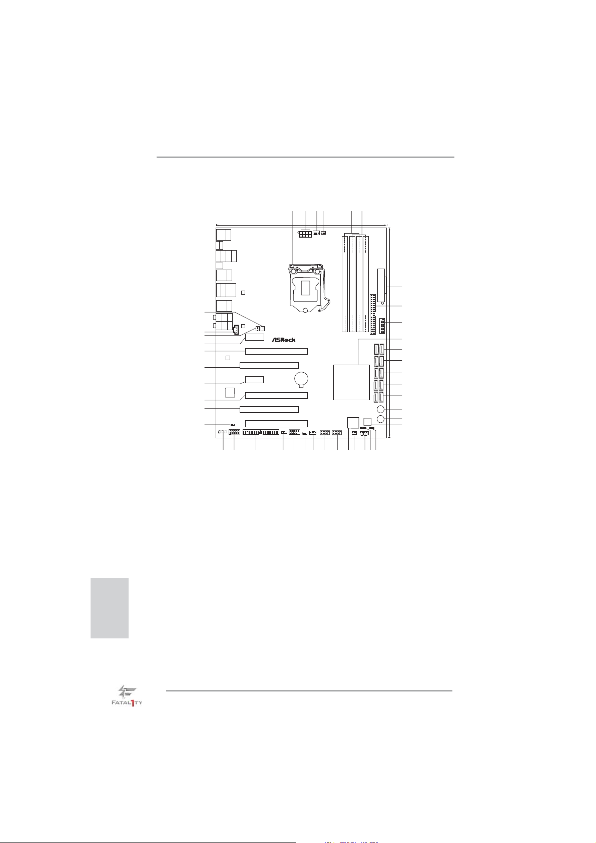
Motherboard Layout
24.4cm (9.6in)
Keyboard/
Mouse
USB3.0
PS2
T:U SB 0
B:USB1
HDMI1
DP1
USB2.0: USB0
USB2.0: USB1
USB2.0: USB2
USB2.0: USB3
Clr
CMOS
USB3.0
Top:
T:U SB 2
RJ-45
B:USB3
IEEE1394
ESATA_1
USB2.0
T:USB4
LAN
B:USB5
PHY
USB3.0
Top:
T:U SB 4
RJ-45
B:USB5
43
42
41
40
39
38
37
36
35
34
33
Top:
Central/Bass
Center:
REAR SPK
Bottom:
Optical
SPDIF
Bottom:
MIC IN
Top:
LINE IN
Center:
FRONT
CD1
LAN
PHY
CHA_FAN2
PWR_FAN1
PCIE1
Z77 PROFESSIONAL
X
X
FLOPPY1
FastLAN
PCIE3
FastRAM
PCIE2
PCI1
PCIE4
ErP/EuPReady
PCI2
FATAL TY
1
PCIE5
IR1
1
1
AUDIO
CODEC
Designedin Taipei
X
FastUSB
Super
I/O
RoHS
1
HDMI_SPDIF1
COM1
HD_AUDIO1
1
1
2
1
3
4
CPU_FAN2
CPU_FAN1
ATX12V1
CMOS
Battery
FRONT_1394
USB8_91USB6_7
CHA_FAN1
CLRCMOS1
1
1
5
DDR3 2800+
DDR3_A2(64 bit, 240-pinmodule)
DDR3_A1(64 bit, 240-pinmodule)
PCI Express3.0
Intel
Z77
Dr.
Debug
CHA_FAN3
6
DDR3_B2(64 bit, 240-pinmodule)
DDR3_B1(64 bit, 240-pinmodule)
Front USB3.0
64Mb
BIOS
SPEAKER1
1
PLEDPWRBTN
1
HDLEDRESET
PANEL1
30.5cm (12.0in)
USB3_6_7
PWRBTN
RSTBTN
ATXPWR1
7
8
9
10
11
12
13
14
15
16
17
18
IDE1
ATA3_0_1 SATA3_A1_A2 SATA3_A3_A4
SATA2_4_5 SATA2_2_3 S
PLED1
1
English
31
32
30
1 1155-Pin CPU Socket
2 ATX 12V Power Connector (ATX12V1)
3 CPU Fan Connector (CPU_FAN1)
4 CPU Fan Connector (CPU_FAN2)
5 2 x 240-pin DDR3 DIMM Slots
(DDR3_A1, DDR3_B1, Red)
6 2 x 240-pin DDR3 DIMM Slots
(DDR3_A2, DDR3_B2, Black)
7 ATX Power Connector (ATXPWR1)
8 Primary IDE Connector (IDE1, Black)
9 USB 3.0 Header (USB3_6_7, Black)
10 Intel Z77 Chipset
11 SATA3 Connectors (SATA3_A3_A4, Red)
12 SATA3 Connectors (SATA3_A1_A2, Red)
13 SATA3 Connectors (SATA3_0_1, Red)
14 SATA2 Connectors (SATA2_2_3, Black)
15 SATA2 Connectors (SATA2_4_5, Black)
16 Power Switch (PWRBTN)
17 Reset Switch (RSTBTN)
18 SPI Flash Memory (64Mb)
19 Power LED Header (PLED1)
20 Chassis Speaker Header (SPEAKER1, Black)
21 System Panel Header (PANEL1, Black)
22 Chassis Fan Connector (CHA_FAN3)
4
Fatal1ty Z77 Professional Series Motherboard
25
28
27
26
29
24
19
2122
20
23
23 Dr. Debug
24 USB 2.0 Header (USB_6_7, Black)
25 USB 2.0 Header (USB_8_9, Black)
26 Chassis Fan Connector (CHA_FAN1)
27 Clear CMOS Jumper (CLRCMOS1)
28 Front Panel IEEE 1394 Header
(FRONT_1394, Red)
29 Infrared Module Header (IR1)
30 Floppy Connector (FLOPPY1)
31 COM Port Header (COM1)
32 Front Panel Audio Header
(HD_AUDIO1, Black)
33 HDMI_SPDIF Header
(HDMI_SPDIF1, Black)
34 PCI Express 2.0 x16 Slot (PCIE5, Red)
35 PCI Slot (PCI2, Black)
36 PCI Express 3.0 x16 Slot (PCIE4, Red)
37 PCI Express 2.0 x1 Slot (PCIE3, Black)
38 PCI Slot (PCI1, Black)
39 PCI Express 3.0 x16 Slot (PCIE2, Red)
40 PCI Express 2.0 x1 Slot (PCIE1, Black)
41 Power Fan Connector (PWR_FAN1)
42 Internal Audio Connector: CD1 (Black)
43 Chassis Fan Connector (CHA_FAN2)
Page 5
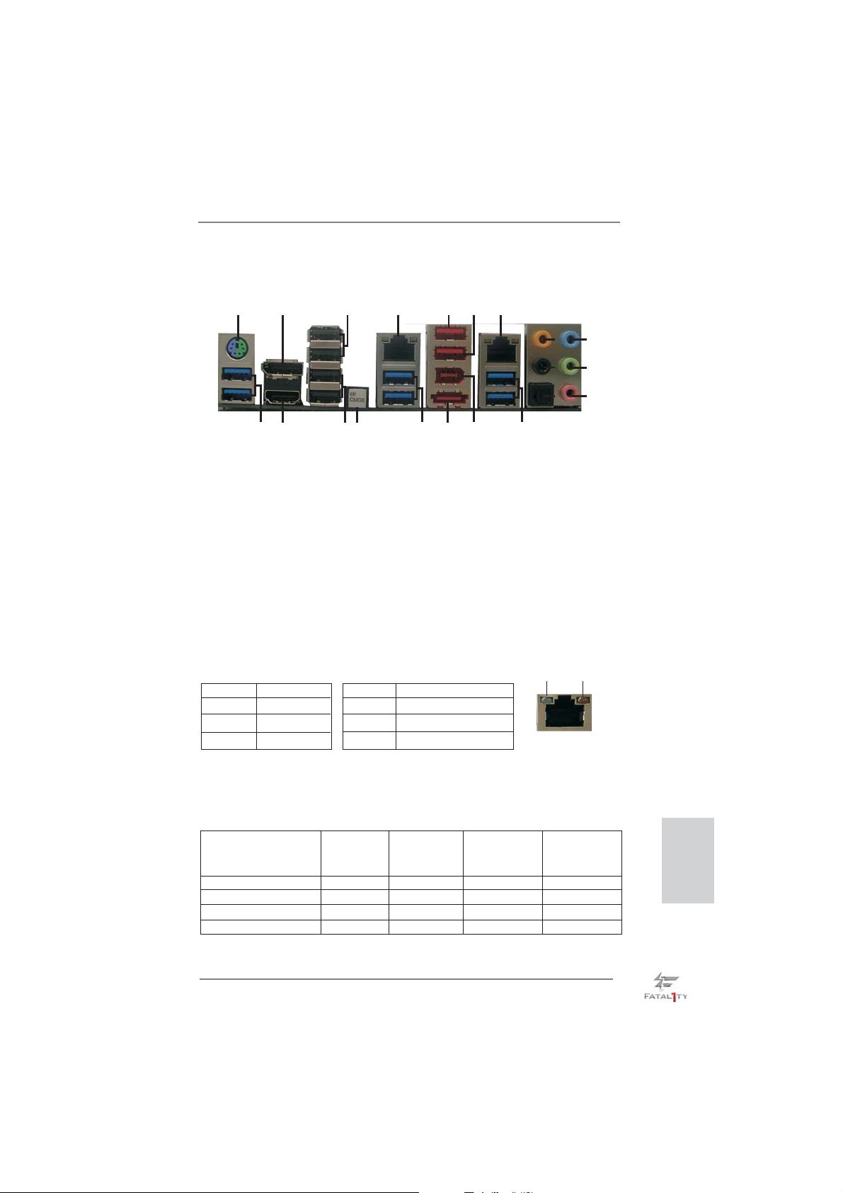
I/O Panel
19
3
18
4
17
1
1 PS/2 Keyboard/Mouse Port (Purple/Green) ** 12 Front Speaker (Lime)
2 DisplayPort (DP1) 13 Microphone (Pink)
3 USB 2.0 Ports (USB01) 14 USB 3.0 Ports (USB3_45)
* 4 LAN RJ-45 Port 15 IEEE 1394 Port
5 Fatal1ty Mouse Port (USB4) *** 16 eSATA3 Port (ESATA_1)
6 USB 2.0 Port (USB5) 17 USB 3.0 Ports (USB3_23)
* 7 LAN RJ-45 Port 18 Clear CMOS Switch (CLRCBTN)
8 Central / Bass (Orange) 19 USB 2.0 Ports (USB23)
9 Rear Speaker (Black) 20 HDMI Port (HDMI1)
10 Optical SPDIF Out Port 21 USB 3.0 Ports (USB3_01)
11 Line In (Light Blue)
* There are two LED next to the LAN port. Please refer to the table below for the LAN port LED
indications.
Activity/Link LED SPEED LED
Status Description Status Description
2
2021
LAN Port LED Indications
16
6
5
15
7
14
ACT/LINK
LED
8
9
10
11
12
13
SPEED
LED
Off No Link Off 10Mbps connection
Blinking Data Activity Orange 100Mbps connection
On Link Green 1Gbps connection
LAN Port
If you use 2-channel speaker, please connect the speaker’s plug into “Front Speaker Jack”.
**
See the table below for connection details in accordance with the type of speaker you use.
TABLE for Audio Output Connection
Audio Output Channels Front Speaker Rear Speaker Central / Bass Line in
(No. 12) (No. 9) (No. 8) (No. 11)
2 V -- -- -4 V V -- -6 V V V -8 V V V V
Fatal1ty Z77 Professional Series Motherboard
English
5
Page 6

To enable Multi-Streaming function, you need to connect a front panel audio cable to the front
panel audio header. After restarting your computer, you will fi nd “Mixer” tool on your system.
Please select “Mixer ToolBox” , click “Enable playback multi-streaming”, and click
“ok”. Choose “2CH”, “4CH”, “6CH”, or “8CH” and then you are allowed to select “Realtek HDA
Primary output” to use Rear Speaker, Central/Bass, and Front Speaker, or select “Realtek
HDA Audio 2nd output” to use front panel audio.
*** eSATA3 connector supports SATA Gen3 in cable 1M.
English
6
Fatal1ty Z77 Professional Series Motherboard
Page 7
1. Introduction
Thank you for purchasing ASRock Fatal1ty Z77 Professional Series motherboard,
a reliable motherboard produced under ASRock’s consistently stringent quality control. It delivers excellent performance with robust design conforming to ASRock’s
commitment to quality and endurance.
This Quick Installation Guide contains introduction of the motherboard and step-bystep installation guide. More detailed information of the motherboard can be found
in the user manual presented in the Support CD.
Because the motherboard specifi cations and the BIOS software might be
updated, the content of this manual will be subject to change without notice. In case any modifi cations of this manual occur, the updated version
will be available on ASRock website without further notice. You may fi nd
the latest VGA cards and CPU support lists on ASRock website as well.
ASRock website http://www.asrock.com
If you require technical support related to this motherboard, please visit
our website for specifi c information about the model you are using.
www.asrock.com/support/index.asp
1.1 Package Contents
ASRock Fatal1ty Z77 Professional Series Motherboard
(ATX Form Factor: 12.0-in x 9.6-in, 30.5 cm x 24.4 cm)
ASRock Fatal1ty Z77 Professional Series Quick Installation Guide
ASRock Fatal1ty Z77 Professional Series Support CD
6 x Serial ATA (SATA) Data Cables (Optional)
2 x Serial ATA (SATA) HDD Power Cables (Optional)
1 x I/O Panel Shield
1 x Front USB 3.0 Panel
4 x HDD Screws
6 x Chassis Screws
1 x Rear USB 3.0 Bracket
1 x ASRock SLI_Bridge_2S Card
ASRock Reminds You...
To get better performance in Windows® 7 / 7 64-bit / Vista
bit, it is recommended to set the BIOS option in Storage Confi guration to
AHCI mode. For the BIOS setup, please refer to the “User Manual” in our
support CD for details.
TM
/ VistaTM 64-
Fatal1ty Z77 Professional Series Motherboard
English
7
Page 8
English
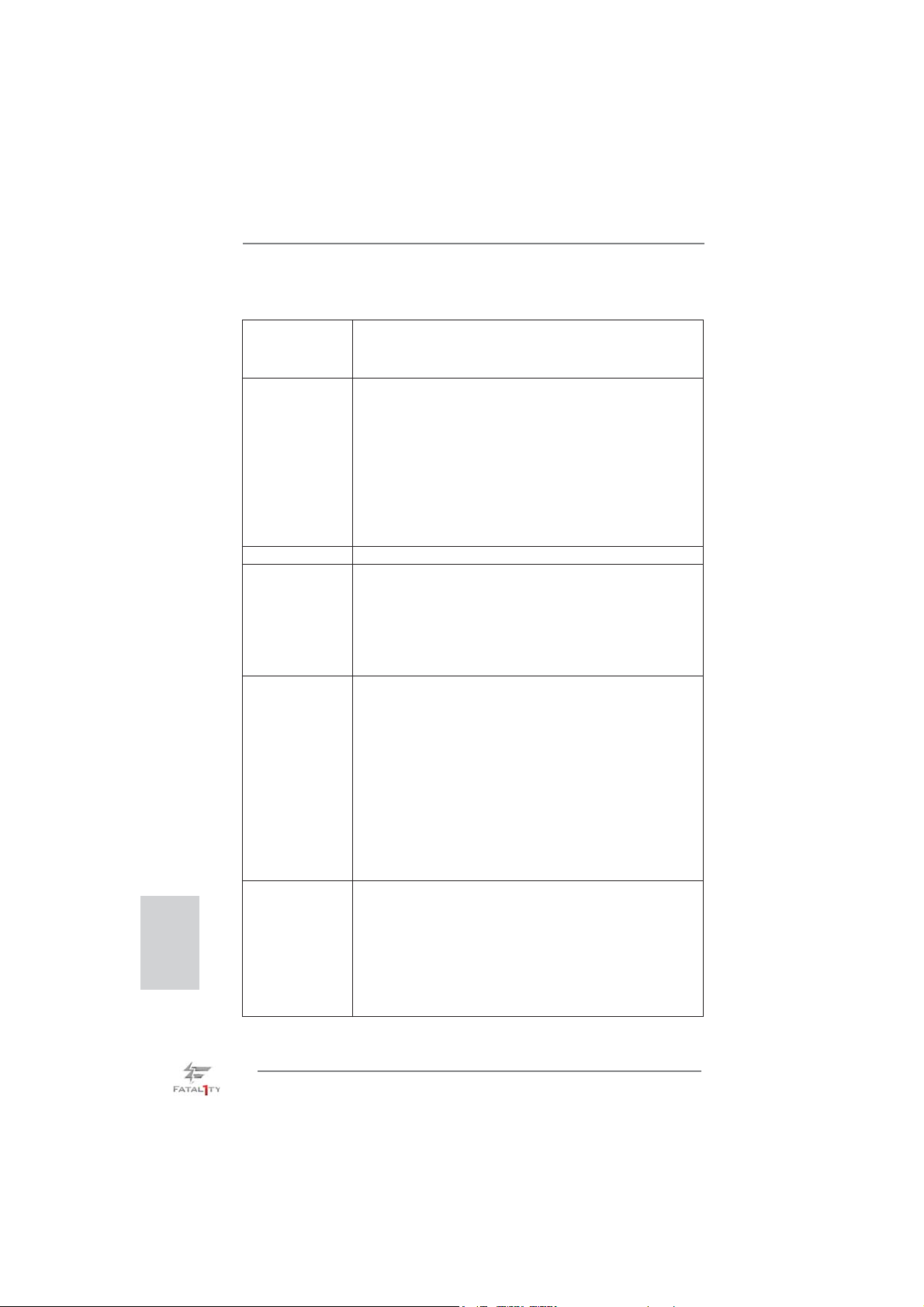
1.2 Specifications
Platform - ATX Form Factor: 12.0-in x 9.6-in, 30.5 cm x 24.4 cm
- Premium Gold Capacitor design (100% Japan-made
high-quality Conductive Polymer Capacitors)
CPU - Supports 3
LGA1155 Package
- Digi Power Design
- 16 + 8 Power Phase Design
- Supports Intel® Turbo Boost 2.0 Technology
- Supports Intel
- Supports Hyper-Threading Technology (see CAUTION 1)
- Supports Intel® Rapid Start Technology and Smart Connect
Technology with Intel
Chipset - Intel® Z77
Memory - Dual Channel DDR3 Memory Technology (see CAUTION 2)
- 4 x DDR3 DIMM slots
- Supports DDR3 2800+(OC)/2400(OC)/2133(OC)/1866(OC)/
1600/1333/1066 non-ECC, un-buffered memory
- Max. capacity of system memory: 32GB (see CAUTION 3)
- Supports Intel
Expansion Slot - 2 x PCI Express 3.0 x16 slots (PCIE2/PCIE4: single at x16
(PCIE2) / x8 (PCIE4) or dual at x8/x8 mode)
(see CAUTION 4)
* PCIE 3.0 is only supported with Intel
Intel® Sandy Bridge CPU, it only supports PCIE 2.0.
- 1 x PCI Express 2.0 x16 slot (PCIE5: x4 mode)
- 2 x PCI Express 2.0 x 1 slots
- 2 x PCI slots
- Supports AMD Quad CrossFireX
CrossFireX
- Supports NVIDIA® Quad SLITM and SLI
Graphics * Intel® HD Graphics Built-in Visuals and the VGA outputs can
be supported only with processors which are GPU
integrated.
- Supports Intel
Sync Video, Intel® InTruTM 3D, Intel® Clear Video HD
Technology, Intel
Intel® Advanced Vector Extensions (AVX)
rd
and 2nd Generation Intel® CoreTM i7 / i5 / i3 in
®
K-Series unlocked CPU
®
Ivy Bridge CPU
®
Extreme Memory Profi le (XMP)1.3/1.2
®
Ivy Bridge CPU. With
TM
TM
®
HD Graphics Built-in Visuals: Intel® Quick
®
InsiderTM, Intel® HD Graphics 2500/4000,
, 3-Way CrossFireXTM and
TM
8
Fatal1ty Z77 Professional Series Motherboard
Page 9
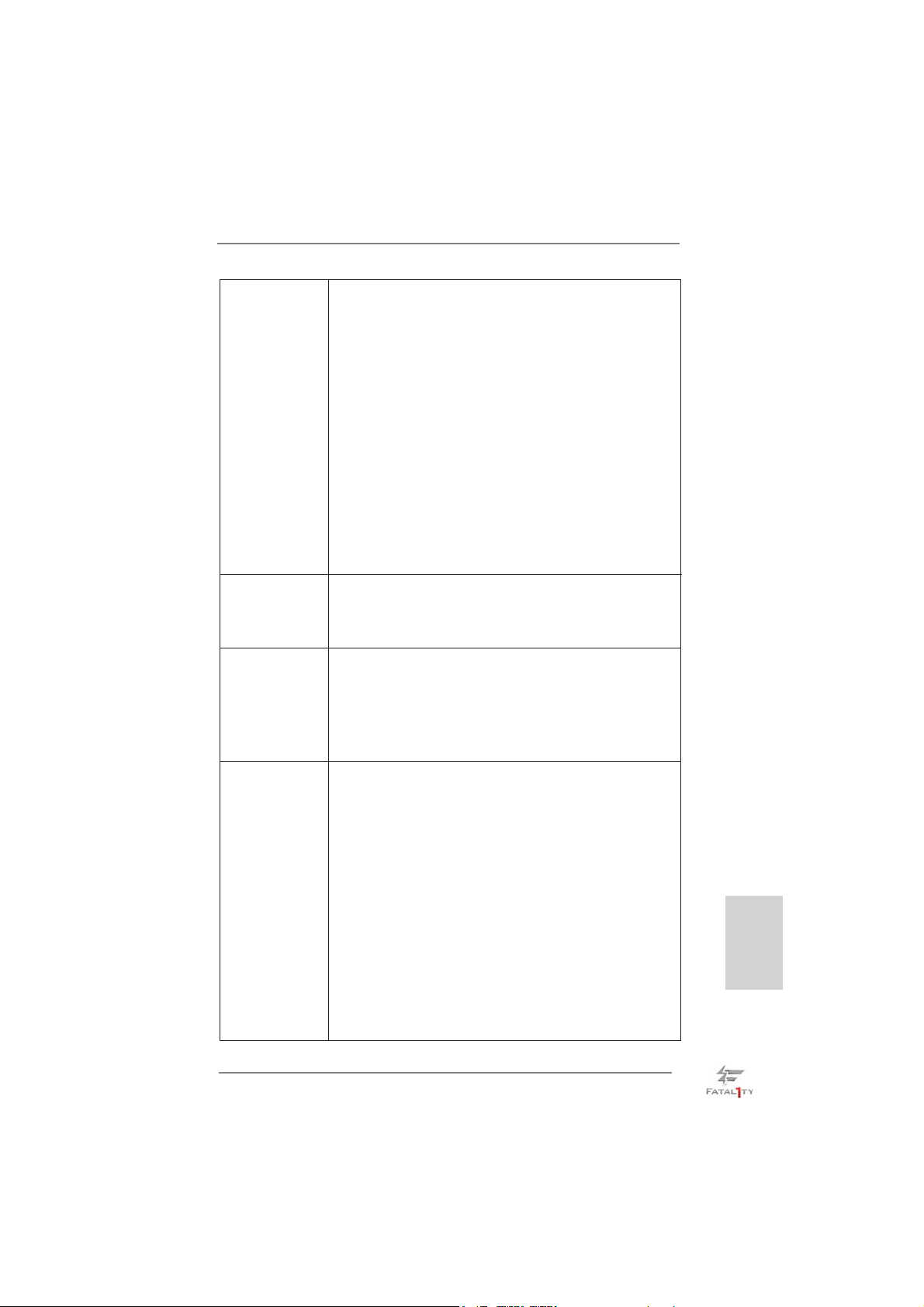
- Pixel Shader 5.0, DirectX 11 with Intel® Ivy Bridge CPU.
Pixel Shader 4.1, DirectX 10.1 with Intel® Sandy Bridge
CPU.
- Max. shared memory 1760MB (see CAUTION 5)
- Dual VGA Output: support HDMI and DisplayPort ports by
independent display controllers
- Supports HDMI 1.4a Technology with max. resolution up to
1920x1200 @ 60Hz
- Supports DisplayPort with max. resolution up to 2560x1600
@ 60Hz
- Supports Auto Lip Sync, Deep Color (12bpc), xvYCC and
HBR (High Bit Rate Audio) with HDMI (Compliant HDMI
monitor is required) (see CAUTION 6)
- Supports HDCP function with HDMI and DisplayPort ports
- Supports Full HD 1080p Blu-ray (BD) / HD-DVD playback
with HDMI and DisplayPort ports
Audio - 7.1 CH HD Audio with Content Protection
(Realtek ALC898 Audio Codec)
- Premium Blu-ray audio support
- Supports THX TruStudio
TM
LAN - PCIE x1 Gigabit LAN 10/100/1000 Mb/s
- Broadcom BCM57781
- Supports Wake-On-LAN
- Supports Energy Effi cient Ethernet 802.3az
- Supports Dual LAN with Teaming function
- Supports PXE
Rear Panel I/O I/O Panel
- 1 x PS/2 Keyboard/Mouse Port
- 1 x HDMI Port
- 1 x DisplayPort
- 1 x Optical SPDIF Out Port
- 5 x Ready-to-Use USB 2.0 Ports
- 1 x Fatal1ty Mouse Port (USB 2.0)
- 1 x eSATA3 Connector
- 6 x Ready-to-Use USB 3.0 Ports
- 2 x RJ-45 LAN Ports with LED (ACT/LINK LED and SPEED
LED)
- 1 x IEEE 1394 Port
- 1 x Clear CMOS Switch with LED
- HD Audio Jack: Rear Speaker/Central/Bass/Line in/Front
Speaker/Microphone (see CAUTION 7)
English
Fatal1ty Z77 Professional Series Motherboard
9
Page 10
English
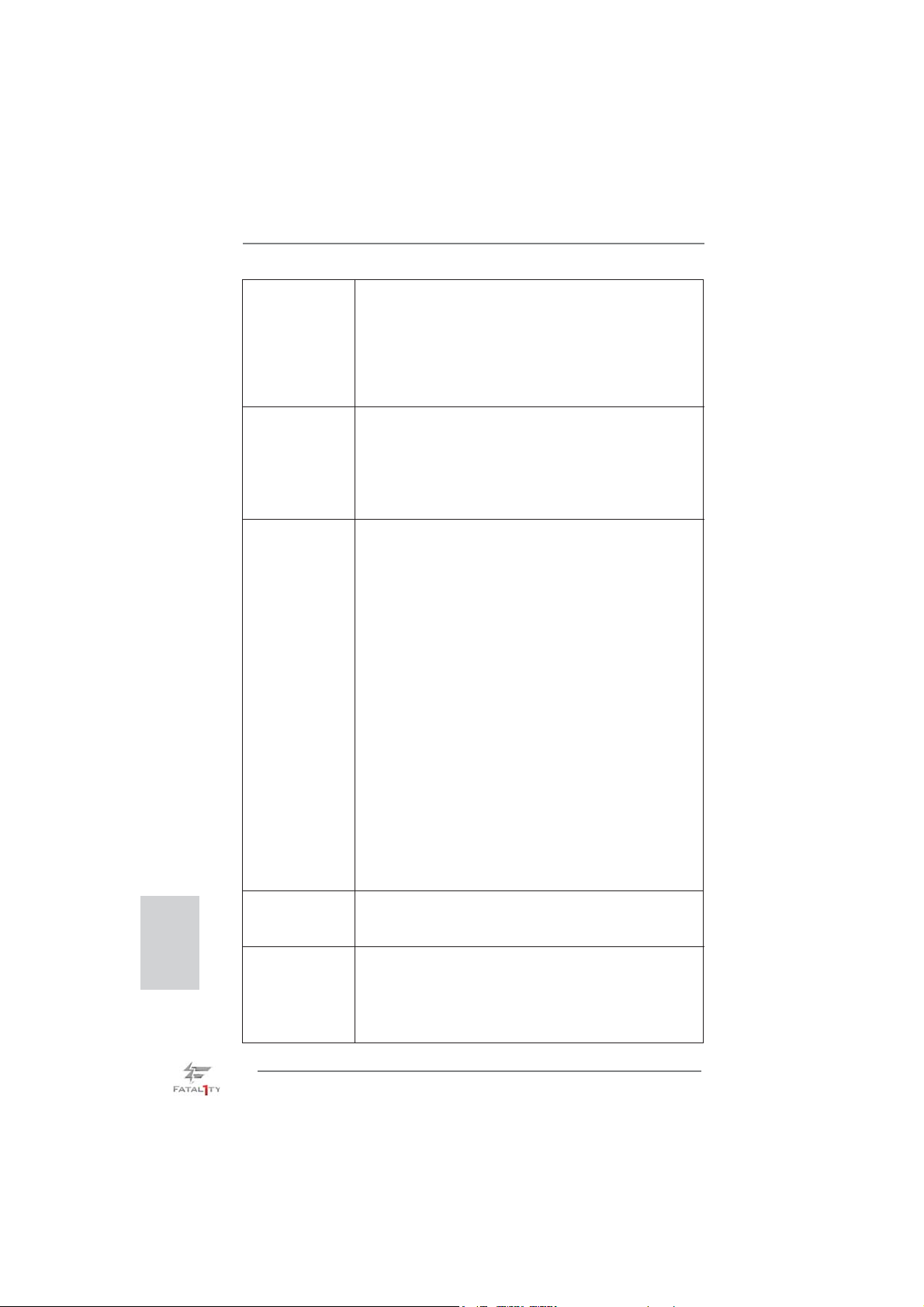
SATA 3 - 2 x SATA3 6.0 Gb/s connectors by Intel® Z77, support RAID
(RAID 0, RAID 1, RAID 5, RAID 10, Intel Rapid Storage and
Intel Smart Response Technology), NCQ, AHCI and Hot
Plug functions
- 4 x SATA3 6.0 Gb/s connectors by ASMedia ASM1061,
support NCQ, AHCI and “Hot Plug” functions (SATA3_A4
connector is shared with eSATA3 port)
®
USB3.0 - 2 x Rear USB 3.0 ports by Intel
Z77, support USB 1.0/2.0/3.0
up to 5Gb/s
- 4 x Rear USB 3.0 ports by Etron EJ188H, support
USB 1.0/2.0/3.0 up to 5Gb/s
- 1 x Front USB 3.0 header by Intel
®
Z77 (supports 2 USB 3.0
ports), supports USB 1.0/2.0/3.0 up to 5Gb/s
Connector - 4 x SATA2 3.0 Gb/s connectors, support RAID (RAID 0,
RAID 1, RAID 5, RAID 10, Intel Rapid Storage and Intel
Smart Response Technology), NCQ, AHCI and Hot Plug
functions
- 6 x SATA3 6.0Gb/s connectors
- 1 x ATA133 IDE connector (supports 2 x IDE devices)
- 1 x Floppy connector
- 1 x IR header
- 1 x COM port header
- 1 x HDMI_SPDIF header
- 1 x IEEE 1394 header
- 1 x Power LED header
- CPU/Chassis/Power FAN connector
- 24 pin ATX power connector
- 8 pin 12V power connector
- CD in header
- Front panel audio connector
- 2 x USB 2.0 headers (support 4 USB 2.0 ports)
- 1 x USB 3.0 header (supports 2 USB 3.0 ports)
- 1 x Dr. Debug with LED
Smart Switch - 1 x Clear CMOS Switch with LED
- 1 x Power Switch with LED
- 1 x Reset Switch with LED
BIOS Feature - 64Mb AMI UEFI Legal BIOS with GUI support
- Supports “Plug and Play”
- ACPI 1.1 Compliance Wake Up Events
- Supports jumperfree
- SMBIOS 2.3.1 Support
10
Fatal1ty Z77 Professional Series Motherboard
Page 11
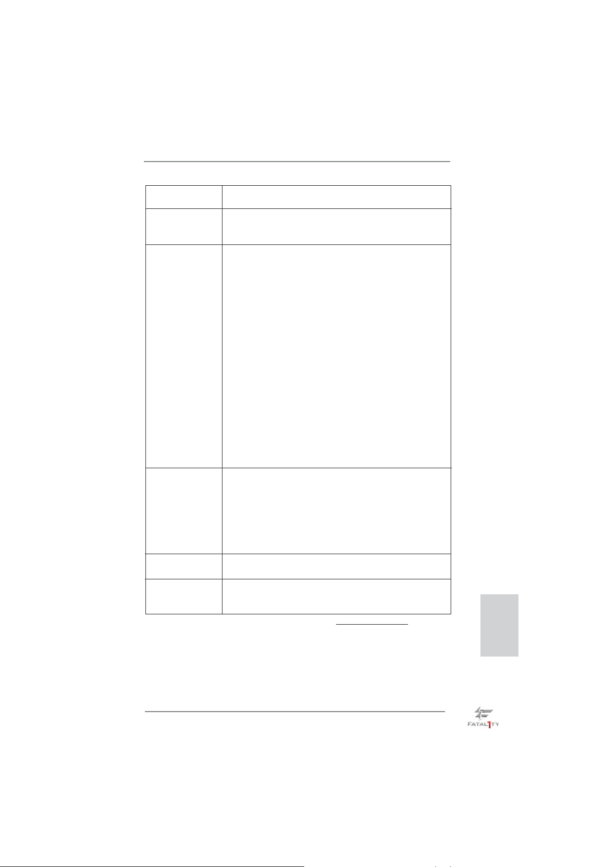
- CPU Core, IGPU, DRAM, 1.8V PLL, VTT, VCCSA Voltage
Multi-adjustment
Support CD - Drivers, Utilities, AntiVirus Software (Trial Version),
CyberLink MediaEspresso 6.5 Trial, ASRock MAGIX
Multimedia Suite - OEM
Unique Feature - F-Stream (see CAUTION 8)
- ASRock Instant Boot
- ASRock Instant Flash (see CAUTION 9)
- ASRock APP Charger (see CAUTION 10)
- ASRock SmartView (see CAUTION 11)
- ASRock XFast USB (see CAUTION 12)
- ASRock XFast LAN (see CAUTION 13)
- ASRock XFast RAM (see CAUTION 14)
- ASRock Crashless BIOS (see CAUTION 15)
- Lucid Virtu Universal MVP (see CAUTION 16)
* Lucid Virtu Universal MVP can be supported only with
processors which are GPU integrated.
- Hybrid Booster:
- CPU Frequency Stepless Control (see CAUTION 17)
- ASRock U-COP (see CAUTION 18)
- Boot Failure Guard (B.F.G.)
- Combo Cooler Option (C.C.O.) (see CAUTION 19)
- Good Night LED
Hardware - CPU Temperature Sensing
Monitor - Chassis Temperature Sensing
- CPU/Chassis/Power Fan Tachometer
- CPU/Chassis Quiet Fan (Allows Chassis Fan Speed Auto Adjust by CPU Temperature)
- CPU/Chassis Fan Multi-Speed Control
- Voltage Monitoring: +12V, +5V, +3.3V, CPU Vcore
OS - Microsoft
®
Windows® 7 / 7 64-bit / VistaTM / VistaTM 64-bit /
XP / XP 64-bit compliant (see CAUTION 20)
Certifi cations - FCC, CE, WHQL
- ErP/EuP Ready (ErP/EuP ready power supply is required)
(see CAUTION 21)
* For detailed product information, please visit our website: http://www.asrock.com
Fatal1ty Z77 Professional Series Motherboard
English
11
Page 12

English
WARNING
Please realize that there is a certain risk involved with overclocking, including
adjusting the setting in the BIOS, applying Untied Overclocking Technology, or using
third-party overclocking tools. Overclocking may affect your system’s stability, or
even cause damage to the components and devices of your system. It should be
done at your own risk and expense. We are not responsible for possible damage
caused by overclocking.
CAUTION!
1. About the settings of “Hyper Threading Technology”, please check page
73 of the “User Manual” in the support CD.
2. This motherboard supports Dual Channel Memory Technology. Before
you implement Dual Channel Memory Technology, make sure to read the
installation guide of memory modules on page 19 for proper installation.
3. Due to the operating system limitation, the actual memory size may be
less than 4GB for the reservation for system usage under Windows
VistaTM / XP. For Windows® OS with 64-bit CPU, there is no such limita-
tion. You can use ASRock XFast RAM to utilize the memory that Win-
dows® cannot use.
4. Only PCIE2 and PCIE4 slots support Gen 3 speed. To run the PCI Express in Gen 3 speed, please install an Ivy Bridge CPU. If you install a
Sandy Bridge
CPU, the PCI Express will run only at PCI Express Gen 2 speed.
5. The maximum shared memory size is defi ned by the chipset vendor and
is subject to change. Please check Intel
tion.
6. xvYCC and Deep Color are only supported under Windows® 7 64-bit /
7. Deep Color mode will be enabled only if the display supports 12bpc
in EDID. HBR is supported under Windows
VistaTM.
7. For microphone input, this motherboard supports both stereo and mono
modes. For audio output, this motherboard supports 2-channel, 4-channel, 6-channel, and 8-channel modes. Please check the table on page 5
for proper connection.
8. F-Stream is an all-in-one tool to fi ne-tune different system functions in a
user-friendly interface, which currently includes Hardware Monitor, Fan
Control, Overclocking, OC DNA, Mouse Polling and IES. In the Hardware
Monitor mode, F-Stream shows the major readings of your system. In
Fan Control mode, F-Stream shows the fan speed and temperature for
you to adjust. In Overclocking Control mode, F-Stream allows you to
overclock the CPU frequency for optimal system performance. In OC
DNA mode, you can save your OC settings as a profi le and share them
with your friends. Your friends can then load the OC profi le in to their own
system to get the same OC settings. In Mouse Polling mode, F-Stream
®
website for the latest informa-
®
7 64-bit / 7 / VistaTM 64-bit /
®
7 /
12
Fatal1ty Z77 Professional Series Motherboard
Page 13

allows you to adjust the mouse polling rate of the Fatal1ty Mouse port to
add a professional level mouse confi guration. In IES (Intelligent Energy
Saver) mode, the voltage regulator can reduce the number of output
phases to improve effi ciency when the CPU cores are idle without sacri-
fi cing computing performance.
9. ASRock Instant Flash is a BIOS fl ash utility embedded in Flash ROM.
This convenient BIOS update tool allows you to update system BIOS
without entering operating systems fi rst like MS-DOS or Windows
this utility, you can press the <F6> key during the POST or the <F2>
key to enter into the BIOS setup menu to access ASRock Instant Flash.
Just launch this tool and save the new BIOS fi le to your USB fl ash drive,
fl oppy disk or hard drive, then you can update your BIOS only in a few
clicks without preparing an additional fl oppy diskette or other complicated
fl ash utility. Please be noted that the USB fl ash drive or hard drive must
use FAT32/16/12 fi le system.
10. If you desire a faster, less restricted way of charging your Apple devices,
such as iPhone/iPad/iPod Touch, ASRock has prepared a wonderful solution for you - ASRock APP Charger. Simply install the APP Charger
driver, it makes your iPhone charge much quickly from your computer
and up to 40% faster than before. ASRock APP Charger allows you to
quickly charge many Apple devices simultaneously and even supports
continuous charging when your PC enters into Standby mode (S1), Sus-
pend to RAM (S3), hibernation mode (S4) or power off (S5). With APP
Charger driver installed, you can easily enjoy the marvelous charging
experience.
ASRock website: http://www.asrock.com/Feature/AppCharger/index.asp
11. ASRock SmartView, a new function for internet browsers, is the smart
start page for IE that combines your most visited web sites, your history,
your Facebook friends and your real-time newsfeed into an enhanced
view for a more personal Internet experience. ASRock motherboards are
exclusively equipped with the ASRock SmartView utility that helps you
keep in touch with friends on-the-go. To use ASRock SmartView feature,
please make sure your OS version is Windows
VistaTM 64 bit, and your browser version is IE8.
ASRock website: http://www.asrock.com/Feature/SmartView/index.asp
12. ASRock XFast USB can boost USB storage device performance. The
performance may depend on the properties of the device.
13. ASRock XFast LAN provides a faster internet access, which includes
the benefi ts listed below. LAN Application Prioritization: You can confi g-
ure your application’s priority ideally and/or add new programs. Lower
Latency in Game: After setting online game’s priority higher, it can lower
the latency in games. Traffi c Shaping: You can watch Youtube HD videos
and download simultaneously. Real-Time Analysis of Your Data: With
the status window, you can easily recognize which data streams you are
transferring currently.
®
7 / 7 64 bit / VistaTM /
®
. With
English
Fatal1ty Z77 Professional Series Motherboard
13
Page 14

English
14. ASRock XFast RAM is a new function that is included into F-Stream. It
fully utilizes the memory space that cannot be used under Windows® OS
32-bit CPU. ASRock XFast RAM shortens the loading time of previously
visited websites, making web surfi ng faster than ever. And it also boosts
the speed of Adobe Photoshop 5 times faster. Another advantage of ASRock XFast RAM is that it reduces the frequency of accessing your SSDs
or HDDs in order to extend their lifespan.
15. ASRock Crashless BIOS allows users to update their BIOS without fear
of failing. If power loss occurs during the BIOS update process, ASRock
Crashless BIOS will automatically fi nish the BIOS update procedure after
regaining power. Please note that BIOS fi les need to be placed in the root
directory of your USB disk. Only USB2.0 ports support this feature.
16. VIRTU Universal MVP includes the base features of Virtu Universal
technology, which virtualizes integrated GPU and discrete GPU for best
of breed functionality. It also features Virtual Vsync™ for no-compromise
visual quality. With the added benefits of HyperFormance technology,
VIRTU Universal MVP improves game performance by intelligently reducing redundant rendering tasks in the fl ow between the CPU, GPU and the
display.
17. Although this motherboard offers stepless control, it is not recommended
to perform over-clocking. Frequencies other than the recommended CPU
bus frequencies may cause instability of the system or damage the CPU.
18. While CPU overheat is detected, the system will automatically shutdown.
Before you resume the system, please check if the CPU fan on the motherboard functions properly and unplug the power cord, then plug it back
again. To improve heat dissipation, remember to spray thermal grease
between the CPU and the heatsink when you install the PC system.
19. Combo Cooler Option (C.C.O.) provides the fl exible option to adopt three
different CPU cooler types, Socket LGA 775, LGA 1155 and LGA 1156.
Please be noticed that not all the 775 and 1156 CPU Fan can be used.
20. ASRock XFast RAM is not supported by Microsoft® Windows® XP / XP
64-bit. Intel® Smart Connect Technology and Intel® USB 3.0 ports are not
supported by Microsoft® Windows® VistaTM / VistaTM 64-bit / XP / XP 64-
bit.
21. EuP stands for Energy Using Product, w
European Union to define the power consumption for the completed
system. According to EuP, the total AC power of the completed system
should be under 1.00W in off mode condition. To meet EuP standards,
an EuP ready motherboard and an EuP ready power supply are required.
According to Intel’s suggestion, the EuP ready power supply must meet
the standard of 5v, and the standby power effi ciency should be higher
than 50% under 100 mA current consumption. For EuP ready power supply selection, we recommend you to check with the power supply manufacturer for more details.
as a provision regulated by the
14
Fatal1ty Z77 Professional Series Motherboard
Page 15

2. Installation
This is an ATX form factor (12.0” x 9.6”, 30.5 x 24.4 cm) motherboard. Before you
install the motherboard, study the confi guration of your chassis to ensure that the
motherboard fi ts into it.
motherboard. Failure to do so may cause physical injuries to you and
damages to motherboard components.
Make sure to unplug the power cord before installing or removing the
2.1 Screw Holes
Place screws into the holes indicated by circles to secure the motherboard to the
chassis.
Do not over-tighten the screws! Doing so may damage the motherboard.
2.2 Pre-installation Precautions
Take note of the following precautions before you install motherboard components
or change any motherboard settings.
1. Unplug the power cord from the wall socket before touching any
components.
2. To avoid damaging the motherboard’s components due to static
electricity, NEVER place your motherboard directly on the carpet
or the like. Also remember to use a grounded wrist strap or touch a
safety grounded object before you handle the components.
3. Hold components by the edges and do not touch the ICs.
4. Whenever you uninstall any component, place it on a grounded antistatic pad or in the bag that comes with the component.
5. When placing screws into the screw holes to secure the motherboard to the chassis, please do not over-tighten the screws! Doing
so may damage the motherboard.
Before you install or remove any component, ensure that the power is
switched off or the power cord is detached from the power supply. Failure to do
so may cause severe damage to the motherboard, peripherals, and/or
components.
Fatal1ty Z77 Professional Series Motherboard
English
15
Page 16
2.3 CPU Installation
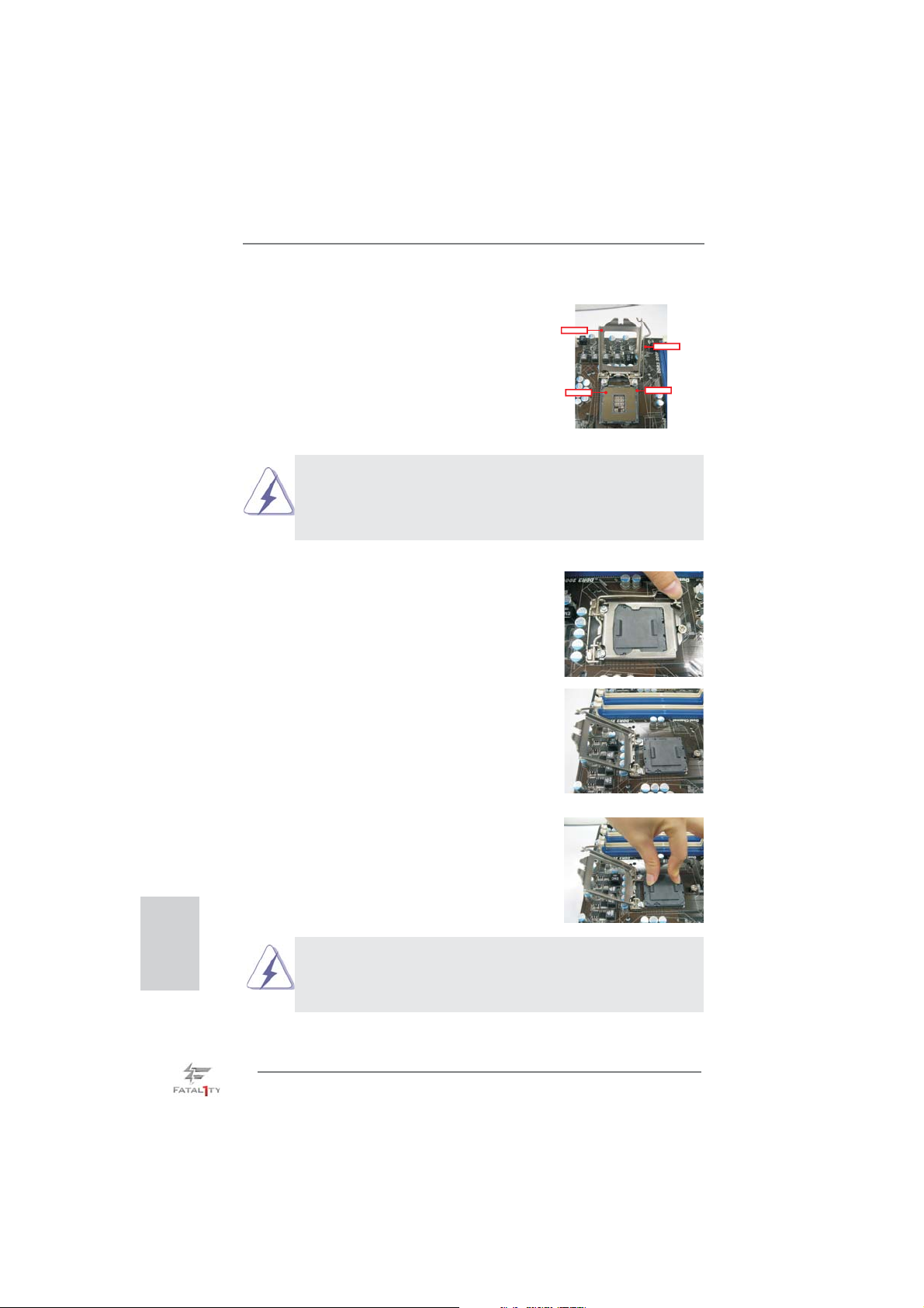
For the installation of Intel 1155-Pin CPU,
please follow the steps below.
LoadPlate
LoadLever
Before you insert the 1155-Pin CPU into the socket, please check if the
CPU surface is unclean or if there are any bent pins in the socket. Do
not force to insert the CPU into the socket if above situation is found.
Otherwise, the CPU will be seriously damaged.
Step 1. Open the socket:
Step 1-1. Disengage the lever by pressing it
down and sliding it out of the hook.
Step 1-2. Keep the lever positioned at about
135 degrees in order to flip up the
load plate.
ContactArray
SocketBody
1155-Pin Socket Overview
English
Step 2. Remove the PnP Cap (Pick and Place Cap).
1. It is recommended to use the cap tab to handle and avoid kicking
off the PnP cap.
2. This cap must be placed if returning the motherboard for after
service.
16
Fatal1ty Z77 Professional Series Motherboard
Page 17
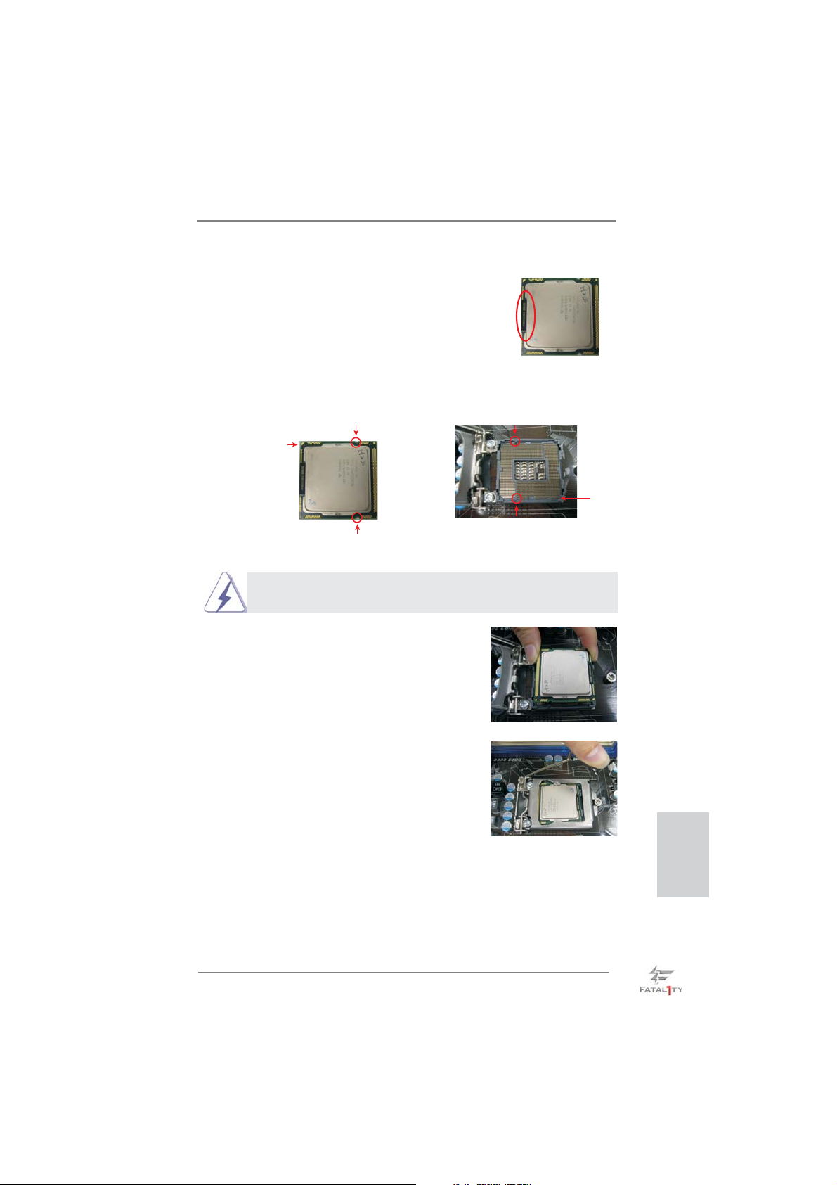
Step 3. Insert the 1155-Pin CPU:
Step 3-1. Hold the CPU by the edge which is
marked with a black line.
Step 3-2. Orient the CPU with the IHS (Inte-
grated Heat Sink) up. Locate Pin1
and the two orientation key notches.
orientation key notch
Pin1
orientation key notch 1155-Pin Socket
1155-Pin CPU
For proper inserting, please ensure to match the two orientation key
notches of the CPU with the two alignment keys of the socket.
Step 3-3. Carefully place the CPU into the
socket by using a purely vertical motion.
Step 3-4. Verify that the CPU is within the sock-
et and properly mated to the orient
keys.
black line
alignment key
Pin1
alignment key
Step 4. Close the socket:
Step 4-1. Flip the load plate onto the IHS.
Step 4-2. Press down the load lever, and se-
cure it with the load plate tab under
the retention tab.
Fatal1ty Z77 Professional Series Motherboard
English
17
Page 18
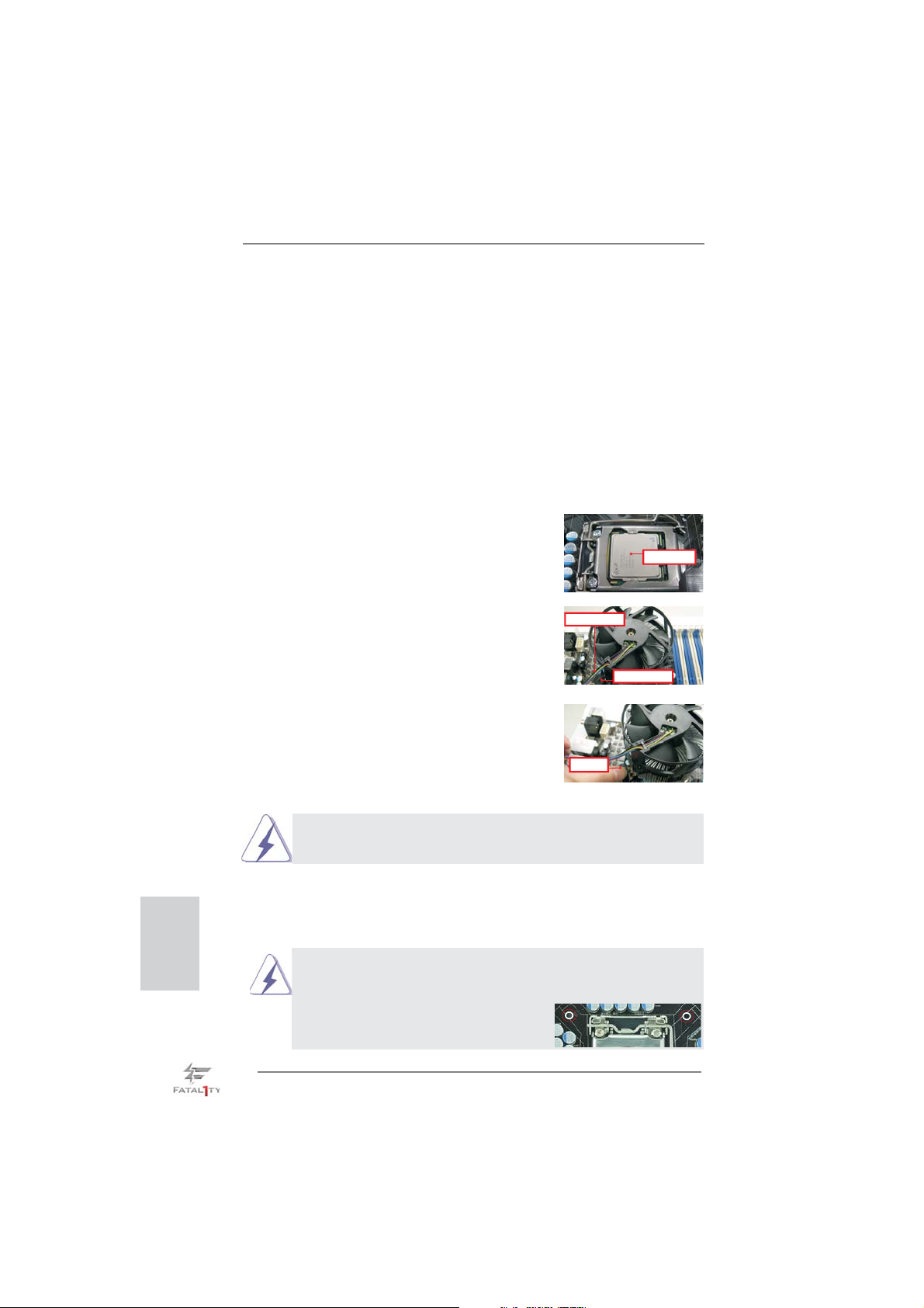
2.4 Installation of CPU Fan and Heatsink
This motherboard is equipped with 1155-Pin socket that supports Intel 1155-Pin
CPUs. Please adopt the type of heatsink and cooling fan compliant with Intel 1155Pin CPU to dissipate heat. Before you install the heatsink, you need to spray thermal interface material between the CPU and the heatsink to improve heat dissipation. Ensure that the CPU and the heatsink are securely fastened and in good contact with each other. Then connect the CPU fan to the CPU_FAN connector (CPU_
FAN1, see page 4, No. 3 or CPU_FAN2, see page 4. No.4).
For proper installation, please kindly refer to the instruction manuals of your
CPU fan and heatsink.
Below is an example to illustrate the installation of the heatsink for 1155-Pin CPUs.
Step 1. Apply thermal interface material onto the cen-
ter of the IHS on the socket’s surface.
Apply Thermal
Interface Material
English
Step 2. Place the heatsink onto the socket. Ensure
that the fan cables are oriented on side closest
Fan cableson side
closest toMB header
to the CPU fan connector on the motherboard
(CPU_FAN1, see page 4, No. 3 or CPU_
FAN2, see page 4. No.4).
Fastener slots
pointing straightout
Step 3. Align fasteners with the motherboard through-
holes.
Step 4. Rotate the fastener clockwise, then press
down on fastener caps with thumb to install
and lock. Repeat with remaining fasteners.
If you press down the fasteners without rotating them clockwise, the
heatsink cannot be secured on the motherboard.
Press Down
(4 Places)
Step 5. Connect fan header with the CPU fan connector on the motherboard.
Step 6. Secure redundant cable with tie-wrap to ensure the cable does not
interfere with fan operation or contact other components.
Please be noticed that this motherboard supports Combo Cooler
Option (C.C.O.), which provides fl exible options to adopt three dif-
ferent CPU cooler types, Socket LGA 775, LGA 1155 and LGA 1156.
The white throughholes are for Socket LGA
1155/1156 CPU fan.
18
Fatal1ty Z77 Professional Series Motherboard
Page 19
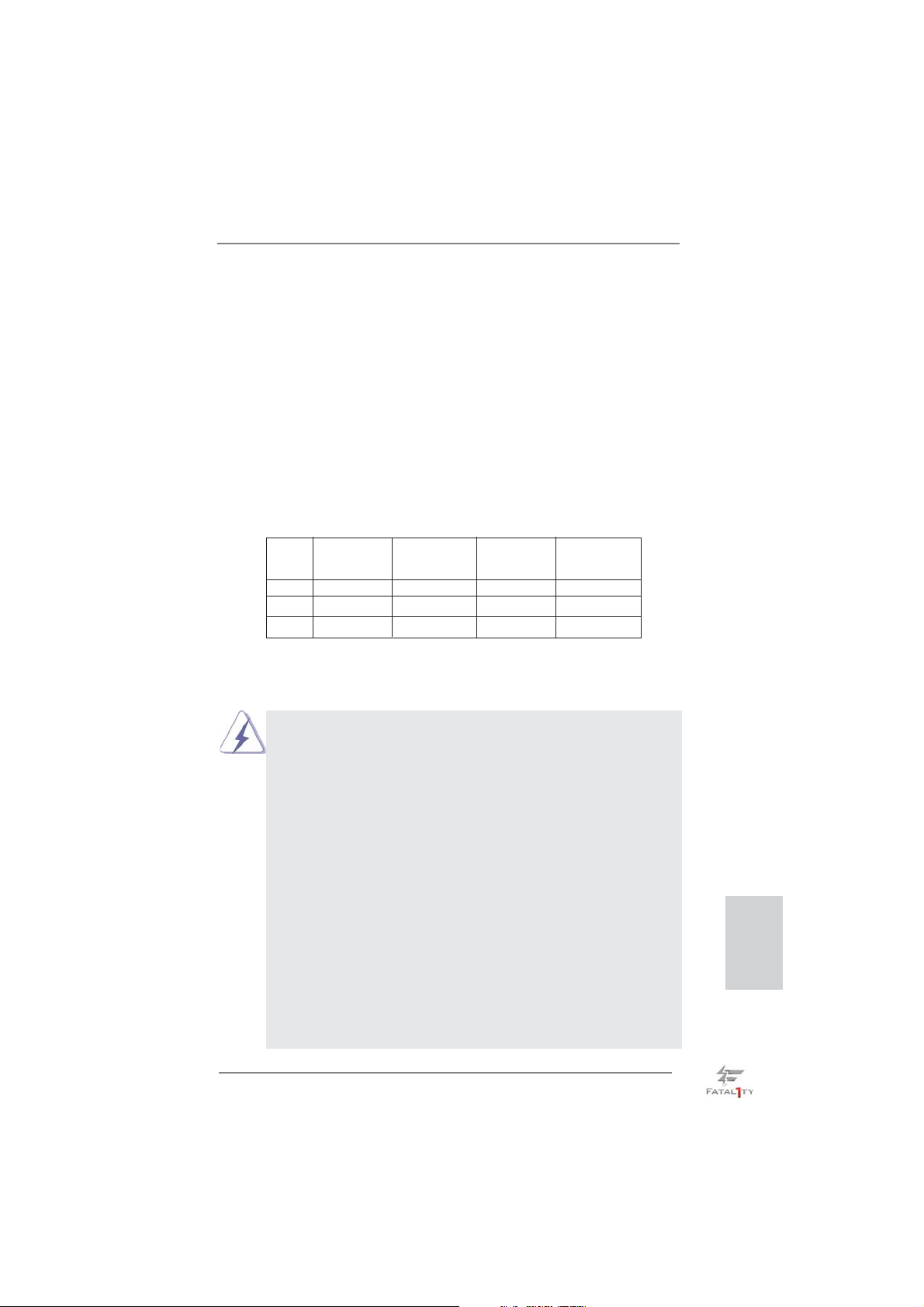
2.5 Installation of Memory Modules (DIMM)
This motherboard provides four 240-pin DDR3 (Double Data Rate 3) DIMM
slots, and supports Dual Channel Memory Technology. For dual channel confi guration, you always need to install identical (the same brand, speed, size
and chip-type) DDR3 DIMM pair in the slots: You have to install identical
DDR3 DIMMs in Dual Channel A (DDR3_A1 and DDR3_B1; Black slots; see p.4
No. 5) or identical DDR3 DIMMs in Dual Channel B (DDR3_A2 and DDR3_
B2; Black slots; see p.4 No. 6), so that Dual Channel Memory Technology can
be activated. This motherboard also allows you to install four DDR3 DIMMs
for dual channel confi guration, please install identical DDR3 DIMMs in all four
slots. You may refer to the Dual Channel Memory Confi guration Table below.
Dual Channel Memory Confi guration
DDR3_A1 DDR3_A2 DDR3_B1 DDR3_B2
(Black Slot) (Black Slot) (Black Slot) (Black Slot)
(1) Populated - Populated (2) - Populated - Populated
(3)* Populated Populated Populated Populated
For confi guration (3), please install identical DDR3 DIMMs in all four
*
slots.
1. If you want to install two memory modules, for optimal compatibility
and reliability, it is recommended to install them in the slots: DDR3_
A1 and DDR3_B1, or DDR3_A2 and DDR3_B2.
2. If only one memory module or three memory modules are installed
in the DDR3 DIMM slots on this motherboard, it is unable to activate
Dual Channel Memory Technology.
3. If a pair of memory modules is NOT installed in the same Dual
Channel, for example, installing a pair of memory modules in
DDR3_A1 and DDR3_A2, it is unable to activate Dual Channel
Memory Technology.
4. It is not allowed to install a DDR or DDR2 memory module into
DDR3 slot; otherwise, this motherboard and DIMM may be damaged.
5. Some DDR3 1GB double-sided DIMMs with 16 chips may not work
on this motherboard. It is not recommended to install them on this
motherboard.
6. For optimal compatibility and stability while overclocking memory
frequency, it is recommended to install one memory module on
DDR3_B2 slot or two memory modules on DDR3_A2 and DDR3_
B2 slots.
English
Fatal1ty Z77 Professional Series Motherboard
19
Page 20
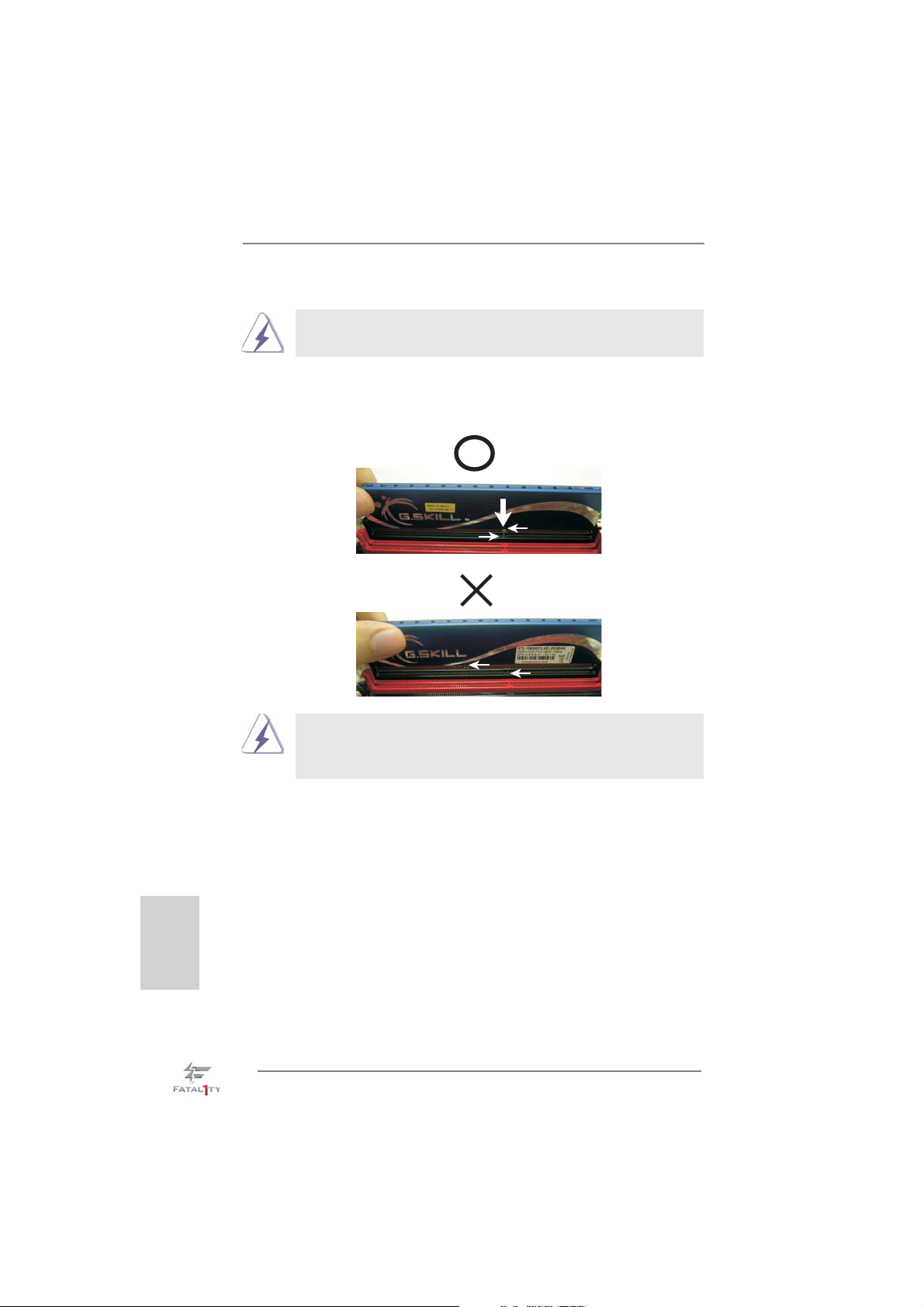
Installing a DIMM
Please make sure to disconnect power supply before adding or
removing DIMMs or the system components.
Step 1. Unlock a DIMM slot by pressing the retaining clips outward.
Step 2. Align a DIMM on the slot such that the notch on the DIMM matches the
break on the slot.
English
notch
notch
break
break
The DIMM only fi ts in one correct orientation. It will cause permanent
damage to the motherboard and the DIMM if you force the DIMM into
the slot at incorrect orientation.
Step 3. Firmly insert the DIMM into the slot until the retaining clips at both ends
fully snap back in place and the DIMM is properly seated.
20
Fatal1ty Z77 Professional Series Motherboard
Page 21

2.6 Expansion Slots (PCI and PCI Express Slots)
There are 2 PCI slots and 5 PCI Express slots on this motherboard.
PCI slots: PCI slots are used to install expansion cards that have the 32-bit PCI
interface.
PCIE slots: PCIE1 (PCIE 2.0 x1 slot) is used for a PCI Express x1 lane width card,
such as a Gigabit LAN card, SATA2 card or ASRock Game Blaster, etc.
PCIE3 (PCIE 2.0 x1 slot) is used for a PCI Express x1 lane width card,
such as a Gigabit LAN card, SATA2 card, etc.
PCIE2 (PCIE 3.0 x16 slot) is used for PCI Express x16 lane width
graphics cards, or to install PCI Express graphics cards to support
CrossFireX
PCIE4 (PCIE 3.0 x16 slot) is used for PCI Express x8 lane width graph-
ics cards, or to install PCI Express graphics cards to support CrossFireX
PCIE5 (PCIE 2.0 x16 slot) is used for PCI Express x4 lane width graph-
ics cards, or to install PCI Express graphics cards to support 3-Way
CrossFireXTM.
1. In single VGA card mode, it is recommended to install a PCI Express
x16 graphics card on PCIE2 slot.
2. In CrossFireXTM mode or SLITM mode, please install the PCI Express
x16 graphics cards on PCIE2 and PCIE4 slots. Therefore, both these
two slots will work at x8 bandwidth.
3. In 3-Way CrossFireXTM mode, please install PCI Express x16
graphics cards on PCIE2, PCIE4 and PCIE5 slots. Therefore, PCIE2
and PCIE4 slots will work at x8 bandwidth while PCIE5 slot will work
at x4 bandwidth.
4. Please connect a chassis fan to the motherboard’s chassis fan
connector (CHA_FAN1, CHA_FAN2 or CHA_FAN3) when using
multiple graphics cards for better thermal environment.
5. Only PCIE2 and PCIE4 slots support Gen 3 speed. To run the PCI
Express in Gen 3 speed, please install an Ivy Bridge CPU. If you
install a Sandy Bridge CPU, the PCI Express will run only at PCI
Express Gen 2 speed.
TM
or SLITM function.
TM
or SLITM function.
Fatal1ty Z77 Professional Series Motherboard
English
21
Page 22

Installing an expansion card
Step 1. Before installing an expansion card, please make sure that the power
supply is switched off or the power cord is unplugged. Please read the
documentation of the expansion card and make necessary hardware
settings for the card before you start the installation.
Step 2. Remove the system unit cover (if your motherboard is already installed
in a chassis).
Step 3. Remove the bracket facing the slot that you intend to use. Keep the
screws for later use.
Step 4. Align the card connector with the slot and press fi rmly until the card is
completely seated on the slot.
Step 5. Fasten the card to the chassis with screws.
Step 6. Replace the system cover.
English
22
Fatal1ty Z77 Professional Series Motherboard
Page 23
2.7 SLITM and Quad SLI
TM
Operation Guide
This motherboard supports NVIDIA® SLITM and Quad SLITM (Scalable Link Interface)
technology that allows you to install up to two identical PCI Express x16 graphics
®
cards. Currently, NVIDIA
SLITM technology supports Windows® XP / XP 64-bit /
VistaTM / VistaTM 64-bit / 7 / 7 64-bit OS. NVIDIA® Quad SLITM technology support
Windows
®
VistaTM / VistaTM 64-bit / 7 / 7 64-bit OS only. Please follow the installation
procedures in this section.
Requirements
1. For SLITM technology, you should have two identical SLITM-ready graphics
cards that are NVIDIA® certifi ed. For Quad SLITM technology, you should
have two identical Quad SLITM-ready graphics cards (dual-GPU on each
graphics card) that are NVIDIA® certifi ed.
2. Make sure that your graphics card driver supports NVIDIA® SLITM
technology. Download the driver from NVIDIA
(www.nvidia.com).
3. Make sure that your power supply unit (PSU) can provide at least the
minimum power required by your system. It is recommended to use
NVIDIA® certifi ed PSU. Please refer to NVIDIA® website for details.
®
website
2.7.1 Graphics Card Setup
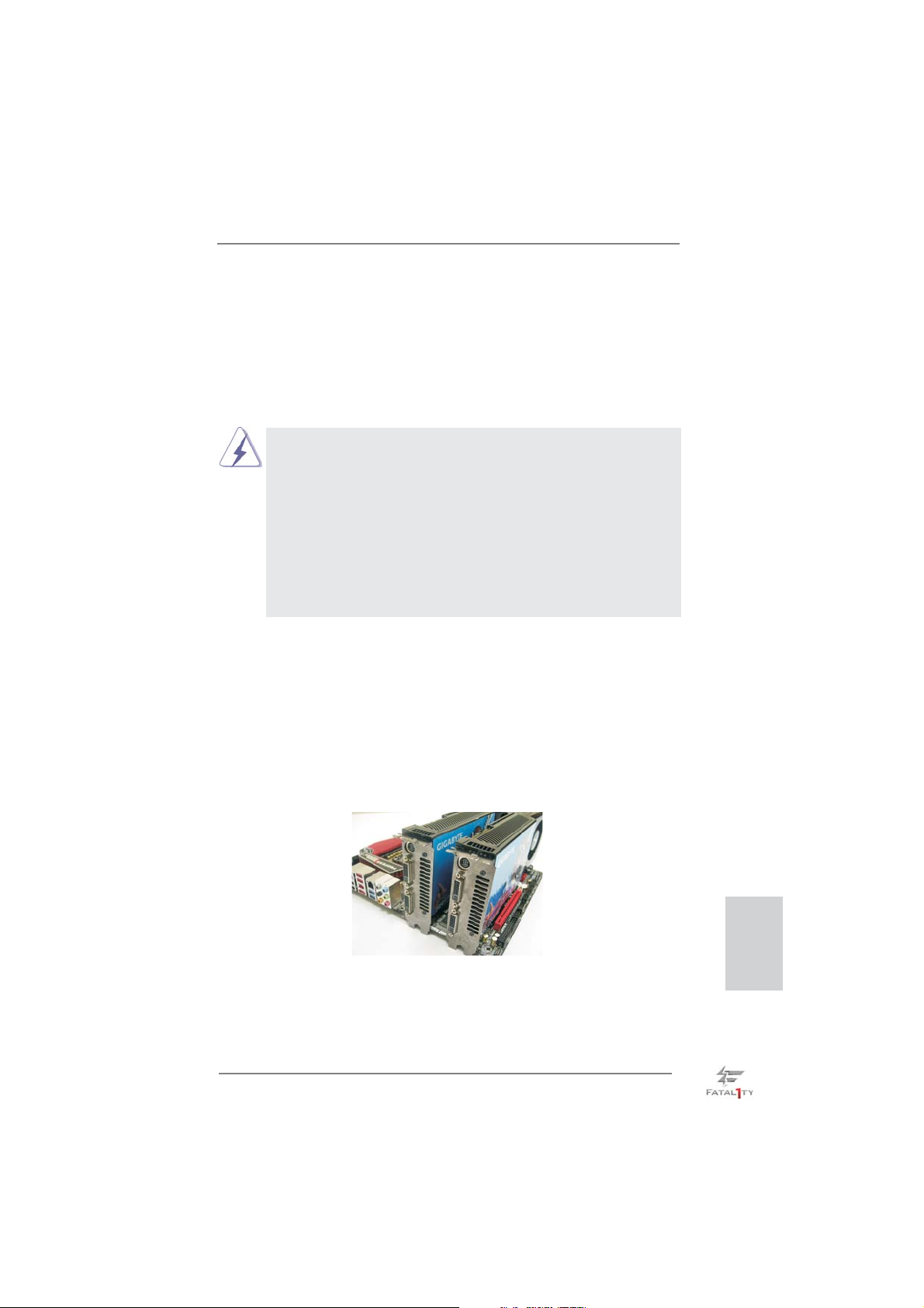
2.7.1.1 Installing Two SLI
TM
-Ready Graphics Cards
Step 1. Install the identical SLITM-ready graphics cards that are NVIDIA® certifi ed
because different types of graphics cards will not work together properly.
(Even the GPU chips version shall be the same.) Insert one graphics card
into PCIE2 slot and the other graphics card to PCIE4 slot. Make sure that
the cards are properly seated on the slots.
Step2. If required, connect the auxiliary power source to the PCI Express
graphics cards.
Fatal1ty Z77 Professional Series Motherboard
English
23
Page 24
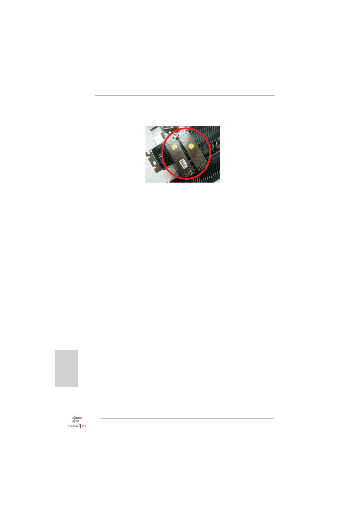
Step3. Align and insert SLI_Bridge_2S Card to the goldfi ngers on each graphics
card. Make sure SLI_Bridge_2S Card is fi rmly in place.
Step4. Connect a VGA cable or a DVI cable to the monitor connector or the DVI
connector of the graphics card that is inserted to PCIE2 slot.
English
24
Fatal1ty Z77 Professional Series Motherboard
Page 25
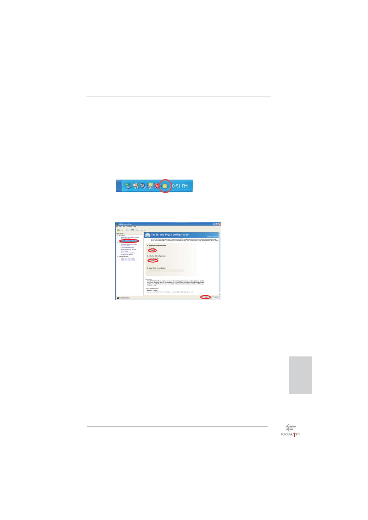
2.7.2 Driver Installation and Setup
Install the graphics card drivers to your system. After that, you can enable the MultiGraphics Processing Unit (GPU) feature in the NVIDIA® nView system tray utility.
Please follow the below procedures to enable the multi-GPU feature.
®
For Windows
(For SLITM mode only)
A. Double-click NVIDIA Settings icon on your Windows® taskbar.
B. From the pop-up menu, select Set SLI and PhysX confi guration. In
Set PhysX GPU acceleration item, please select Enabled. In Select
an SLI confi guration item, please select Enable SLI. And click Apply.
XP / XP 64-bit OS:
C. Reboot your system.
D. You can freely enjoy the benefi t of SLI
Fatal1ty Z77 Professional Series Motherboard
TM
feature.
English
25
Page 26
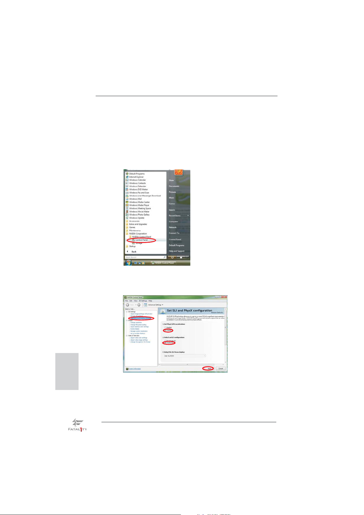
For Windows® VistaTM / VistaTM 64-bit / 7 / 7 64-bit OS:
(For SLITM and Quad SLITM mode)
A. Click the Start icon on your Windows taskbar.
B. From the pop-up menu, select All Programs, and then click NVIDIA
Corporation.
C. Select NVIDIA Control Panel tab.
D. Select Control Panel tab.
E. From the pop-up menu, select Set SLI and PhysX confi guration. In
Set PhysX GPU acceleration item, please select Enabled. In Select
an SLI confi guration item, please select Enable SLI. And click Apply.
English
F. Reboot your system.
G. You can freely enjoy the benefi t of SLITM or Quad SLITM feature.
* SLITM appearing here is a registered trademark of NVIDIA® Technologies Inc., and is used
only for identifi cation or explanation and to the owners’ benefi t, without intent to infringe.
26
Fatal1ty Z77 Professional Series Motherboard
Page 27
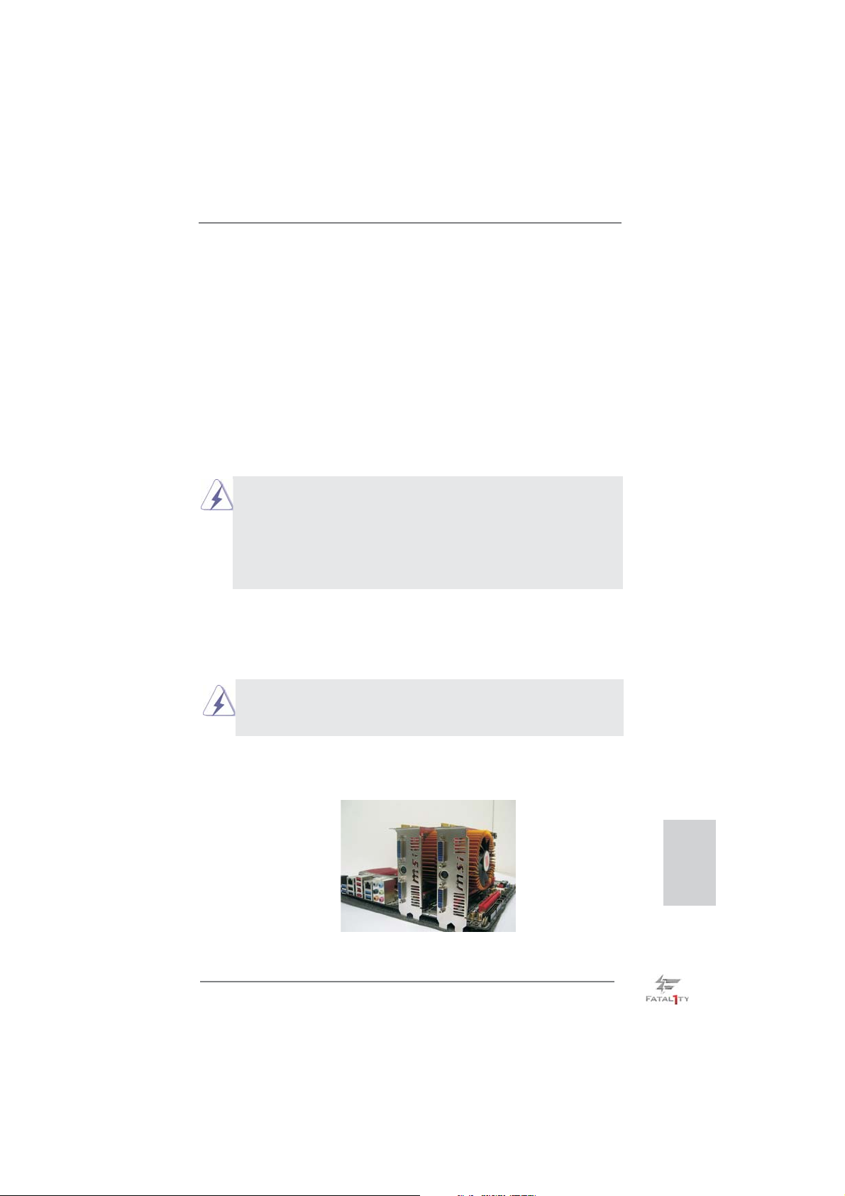
2.8 CrossFireXTM, 3-Way CrossFireXTM and Quad
CrossFireXTM Operation Guide
This motherboard supports CrossFireXTM, 3-way CrossFireX
TM
CrossFireX
feature. CrossFireXTM technology offers the most advantageous
means available of combining multiple high performance Graphics Processing
Units (GPU) in a single PC. Combining a range of different operating modes with
intelligent software design and an innovative interconnect mechanism, CrossFireX
enables the highest possible level of performance and image quality in any 3D
application. Currently CrossFireXTM feature is supported with Windows® XP with
Service Pack 2 / VistaTM / 7 OS. 3-way CrossFireXTM and Quad CrossFireX
are supported with Windows
®
VistaTM / 7 OS only. Please check AMD website for
ATITM CrossFireXTM driver updates.
1. If a customer incorrectly confi gures their system they will not see the
performance benefi ts of CrossFireXTM. All three CrossFireXTM components, a
CrossFireXTM Ready graphics card, a CrossFireXTM Ready motherboard and a
CrossFireXTM Edition co-processor graphics card, must be installed correctly to
benefi t from the CrossFireX
2. If you pair a 12-pipe CrossFireXTM Edition card with a 16-pipe card, both cards
will operate as 12-pipe cards while in CrossFireXTM mode.
TM
multi-GPU platform.
TM
and Quad
TM
feature
TM
2.8.1 Graphics Card Setup
2.8.1.1 Installing Two CrossFireX
Different CrossFireXTM cards may require different methods to enable CrossFireXTM
feature. For other CrossFireXTM cards that AMD has released or will release in the
future, please refer to AMD graphics card manuals for detailed installation guide.
TM
-Ready Graphics Cards
Step 1. Insert one Radeon graphics card into PCIE2 slot and the other Radeon
graphics card to PCIE4 slot. Make sure that the cards are properly seated
on the slots.
Fatal1ty Z77 Professional Series Motherboard
English
27
Page 28
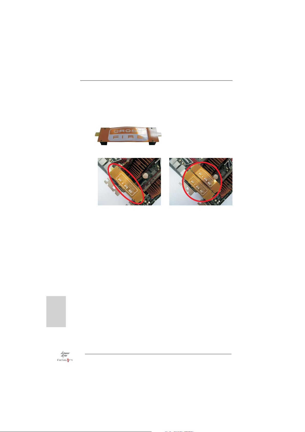
Step 2. Connect two Radeon graphics cards by installing CrossFire Bridge on
CrossFire Bridge Interconnects on the top of Radeon graphics cards.
(CrossFire Bridge is provided with the graphics card you purchase, not
bundled with this motherboard. Please refer to your graphics card vendor
for details.)
CrossFire Bridge
or
Step 3. Connect the DVI monitor cable to the DVI connector on the Radeon
graphics card on PCIE2 slot. (You may use the DVI to D-Sub adapter to
convert the DVI connector to D-Sub interface, and then connect the D-Sub
monitor cable to the DVI to D-Sub adapter.)
English
28
Fatal1ty Z77 Professional Series Motherboard
Page 29
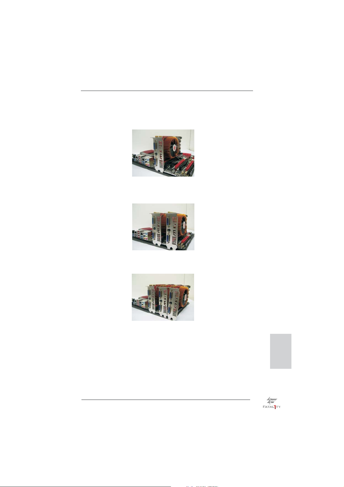
2.8.1.2 Installing Three CrossFireXTM-Ready Graphics Cards
Step 1. Install one Radeon graphics card to PCIE2 slot. For the proper installation
procedures, please refer to section “Expansion Slots”.
Step 2. Install one Radeon graphics card to PCIE4 slot. For the proper installation
procedures, please refer to section “Expansion Slots”.
Step 3. Install one Radeon graphics card to PCIE5 slot. For the proper installation
procedures, please refer to section “Expansion Slots”.
Step 4. Use one CrossFireTM Bridge to connect Radeon graphics cards on PCIE2
and PCIE4 slots, and use the other CrossFireTM Bridge to connect Radeon
graphics cards on PCIE4 and PCIE5 slots. (CrossFireTM Bridge is provided
with the graphics card you purchase, not bundled with this motherboard.
Please refer to your graphics card vendor for details.)
Fatal1ty Z77 Professional Series Motherboard
English
29
Page 30
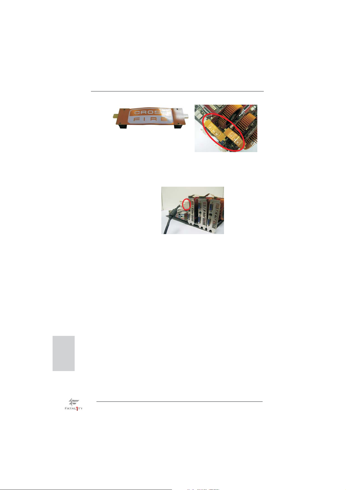
CrossFireTM Bridge
Step 5. Connect the DVI monitor cable to the DVI connector on the Radeon graph-
ics card on PCIE2 slot. (You may use the DVI to D-Sub adapter to convert
the DVI connector to D-Sub interface, and then connect the D-Sub monitor
cable to the DVI to D-Sub adapter.)
English
30
Fatal1ty Z77 Professional Series Motherboard
Page 31
2.8.2 Driver Installation and Setup
Step 1. Power on your computer and boot into OS.
Step 2. Remove the ATITM driver if you have any VGA driver installed in your
system.
The Catalyst Uninstaller is an optional download. We recommend using this
utility to uninstall any previously installed Catalyst drivers prior to installation.
Please check AMD website for ATI
TM
driver updates.
Step 3. Install the required drivers to your system.
For Windows
®
XP OS:
A. ATITM recommends Windows® XP Service Pack 2 or higher to be
installed (If you have Windows® XP Service Pack 2 or higher installed
in your system, there is no need to download it again):
http://www.microsoft.com/windowsxp/sp2/default.mspx
B. You must have Microsoft .NET Framework installed prior to
downloading and installing the CATALYST Control Center. Please
check Microsoft website for details.
For Windows
®
7 / VistaTM OS:
Install the CATALYST Control Center. Please check AMD website for de-
tails.
Step 4. Restart your computer.
Step 5. Install the VGA card drivers to your system, and restart your computer.
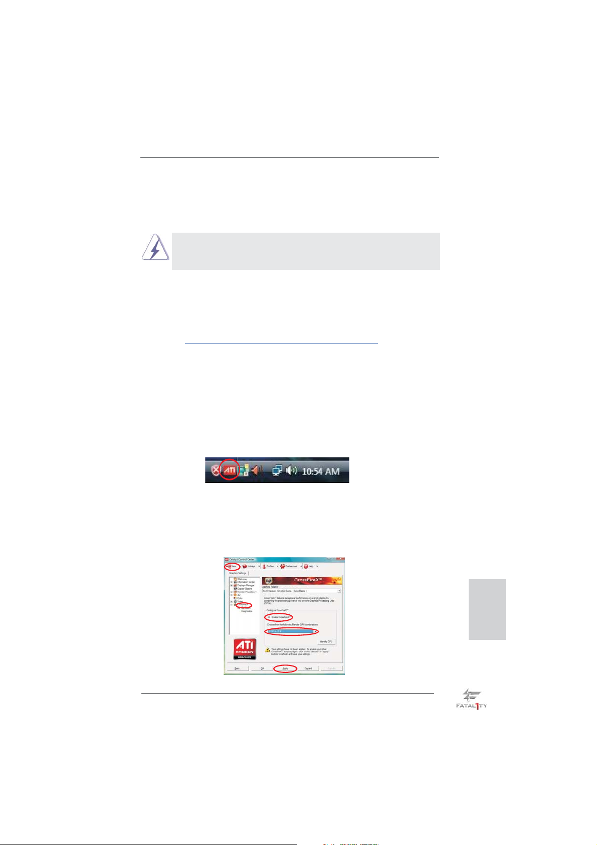
Then you will fi nd “ATI Catalyst Control Center” on your Windows® taskbar.
ATI Catalyst Control Center
Step 6. Double-click “ATI Catalyst Control Center”. Click “View”, select “CrossFi-
TM
reX
”, and then check the item “Enable CrossFireXTM”. Select “2 GPUs”
and click “Apply” (if you install two Radeon graphics cards). Select “3
GPUs” and click “OK” (if you install three Radeon graphics cards).
Fatal1ty Z77 Professional Series Motherboard
English
31
Page 32

Although you have selected the option “Enable CrossFireTM”, the CrossFireXTM
function may not work actually. Your computer will automatically reboot. After
restarting your computer, please confi rm whether the option “Enable
CrossFireTM” in “ATI Catalyst Control Center” is selected or not; if not, please
select it again, and then you are able to enjoy the benefi t of CrossFireX
feature.
TM
Step 7. You can freely enjoy the benefi t of CrossFireXTM, 3-Way CrossFireXTM or
Quad CrossFireXTM feature.
* CrossFireXTM appearing here is a registered trademark of ATITM Technologies Inc., and is
used only for identifi cation or explanation and to the owners’ benefi t, without intent to infringe.
* For further information of ATI
updates and details.
TM
CrossFireXTM technology, please check AMD website for
English
32
Fatal1ty Z77 Professional Series Motherboard
Page 33
2.9 Dual Monitor and Surround Display Features
Dual Monitor Feature
This motherboard supports dual monitor feature. With the internal VGA output support (HDMI and DisplayPort), you can easily enjoy the benefi ts of dual monitor fea-
ture without installing any add-on VGA card to this motherboard. This motherboard
also provides independent display controllers for HDMI and DisplayPort to support
dual VGA output so that HDMI and DisplayPort can drive same or different display
contents.
To enable dual monitor feature, please follow the below steps:
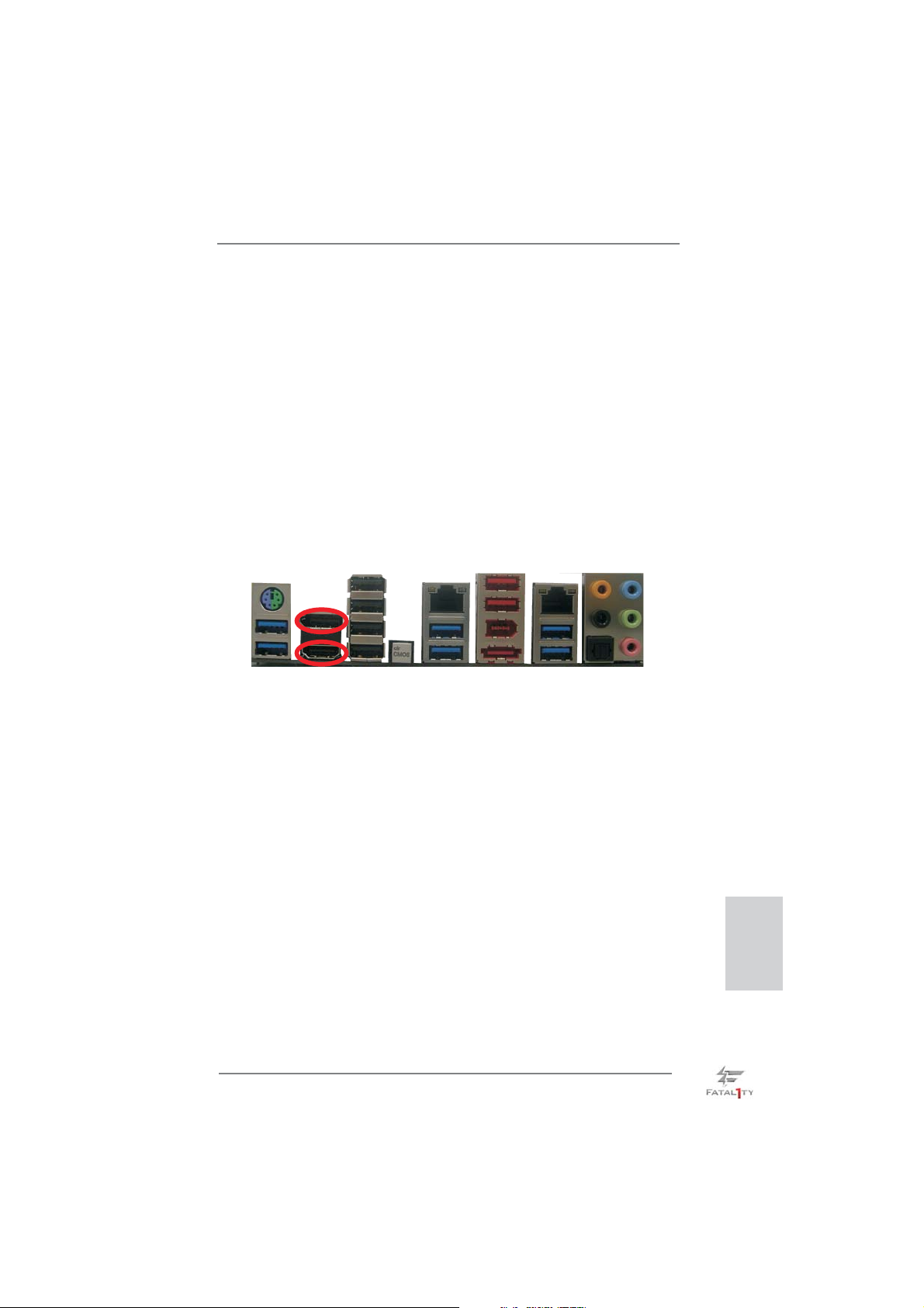
1. Connect HDMI monitor cable to HDMI port on the I/O panel, and connect
DisplayPort monitor cable to DisplayPort on the I/O panel.
DisplayPort
HDMI port
2. If you have installed onboard VGA driver from our support CD to your system
already, you can freely enjoy the benefi ts of dual monitor function after your
system boots. If you haven’t installed onboard VGA driver yet, please install
onboard VGA driver from our support CD to your system and restart your
computer.
Fatal1ty Z77 Professional Series Motherboard
English
33
Page 34

Surround Display Feature
This motherboard supports surround display upgrade. With the internal VGA output
support (HDMI and DisplayPort) and external add-on PCI Express VGA cards, you
can easily enjoy the benefi ts of surround display feature.
Please refer to the following steps to set up a surround display environment:
1. Install the PCI Express VGA cards on PCIE2, PCIE4 and PCIE5 slots. Please
refer to page 21 for proper expansion card installation procedures.
2. Connect HDMI monitor cable to HDMI port on the I/O panel, and connect
DisplayPort monitor cable to DisplayPort on the I/O panel. Then connect other
monitor cables to the corresponding connectors of the add-on PCI Express VGA
cards on PCIE2, PCIE4 and PCIE5 slots.
3. Boot your system. Press <F2> or <Del> to enter UEFI setup. Enter “Share
Memory” option to adjust the memory capability to [32MB], [64MB], [128MB],
[256MB] or [512MB] to enable the function of D-sub. Please make sure that the
value you select is less than the total capability of the system memory. If you do
not adjust the UEFI setup, the default value of “Share Memory”, [Auto], will
disable D-Sub function when an add-on VGA card is inserted to this motherboard.
4. Install the onboard VGA driver and the add-on PCI Express VGA card driver to
your system. If you have installed the drivers already, there is no need to install
them again.
5. Set up a multi-monitor display.
English
For Windows
®
XP / XP 64-bit OS:
Right click on desktop, choose “Properties”, and select the “Settings” tab
so that you can adjust the parameters of the multi-monitors according to
the steps below.
A. Click the “Identify” button to display a large number on each monitor.
B. Right-click the display icon in the Display Properties dialog that you
wish to be your primary monitor, and then select “Primary”. When
you use multiple monitors with your card, one monitor will always be
Primary, and all additional monitors will be designated as Secondary.
C. Select the display icon identifi ed by the number 2.
D. Click “Extend my Windows desktop onto this monitor”.
E. Right-click the display icon and select “Attached”, if necessary.
F. Set the appropriate “Screen Resolution” and “Color Quality” for the
second monitor. Click “Apply” or “OK” to apply these new values.
G. Repeat steps C through E for the display icon identifi ed by the
numbers three to eight.
34
Fatal1ty Z77 Professional Series Motherboard
Page 35

For Windows® 7 / 7 64-bit / VistaTM / VistaTM 64-bit OS:
Right click the desktop, choose “Personalize”, and select the “Display
Settings” tab so that you can adjust the parameters of the multi-monitors
according to the steps below.
A. Click the number ”2” icon.
B. Click the items “This is my main monitor” and “Extend the desktop onto
this monitor”.
C. Click “OK” to save your change.
D. Repeat steps A through C for the display icons identifi ed by the number
three to eight.
6. Use Surround Display. Click and drag the display icons to positions representing
the physical setup of your monitors that you would like to use. The placement of
display icons determines how you move items from one monitor to another.
HDCP Function
HDCP function is supported on this motherboard. To use HDCP
function with this motherboard, you need to adopt a monitor
that supports HDCP function as well. Therefore, you can enjoy
the superior display quality with high-defi nition HDCP
encryption contents. Please refer to the instructions below for
more details about HDCP function.
What is HDCP?
HDCP stands for High-Bandwidth Digital Content Protection, a
specifi cation developed by Intel
®
for protecting digital
entertainment content that uses the DVI interface. HDCP is a
copy protection scheme to eliminate the possibility of
intercepting digital data midstream between the video source,
or transmitter - such as a computer, DVD player or set-top box -
and the digital display, or receiver - such as a monitor, television
or projector. In other words, HDCP specifi cation is designed to
protect the integrity of content as it is being transmitted.
Products compatible with the HDCP scheme such as DVD
players, satellite and cable HDTV set-top-boxes, as well as few
entertainment PCs requires a secure connection to a compliant
display. Due to the increase in manufacturers employing HDCP
in their equipment, it is highly recommended that the HDTV or
LCD monitor you purchase is compatible.
Fatal1ty Z77 Professional Series Motherboard
English
35
Page 36
2.10 Jumpers Setup
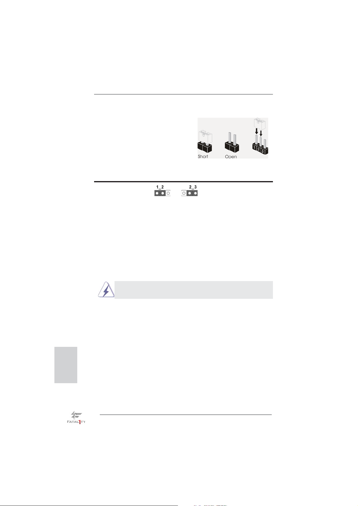
The illustration shows how jumpers are
setup. When the jumper cap is placed on
pins, the jumper is “Short”. If no jumper cap
is placed on pins, the jumper is “Open”. The
illustration shows a 3-pin jumper whose
pin1 and pin2 are “Short” when jumper cap
is placed on these 2 pins.
Jumper Setting Description
Clear CMOS Jumper
(CLRCMOS1)
(see p.4, No. 27)
Note: CLRCMOS1 allows you to clear the data in CMOS. To clear and reset the
system parameters to default setup, please turn off the computer and unplug
the power cord from the power supply. After waiting for 15 seconds, use a
jumper cap to short pin2 and pin3 on CLRCMOS1 for 5 seconds. However,
please do not clear the CMOS right after you update the BIOS. If you need
to clear the CMOS when you just fi nish updating the BIOS, you must boot
up the system fi rst, and then shut it down before you do the clear-CMOS ac-
tion. Please be noted that the password, date, time, user default profi le, 1394
GUID and MAC address will be cleared only if the CMOS battery is removed.
The Clear CMOS Switch has the same function as the Clear CMOS
jumper.
Clear CMOSDefault
English
36
Fatal1ty Z77 Professional Series Motherboard
Page 37
2.11 Onboard Headers and Connectors
Onboard headers and connectors are NOT jumpers. Do NOT place
jumper caps over these headers and connectors. Placing jumper caps
over the headers and connectors will cause permanent damage of the
motherboard!
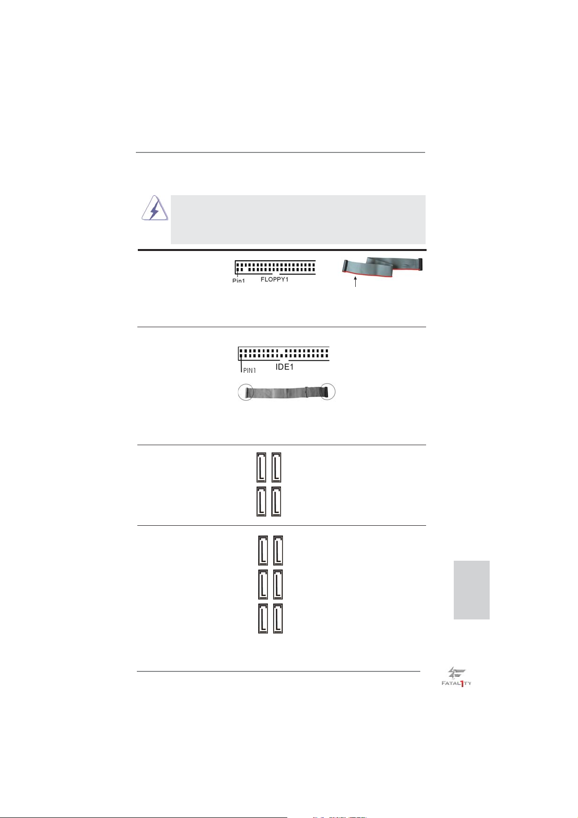
FDD connector
(33-pin FLOPPY1)
(see p.4 No. 30)
the red-striped side to Pin1
Note: Make sure the red-striped side of the cable is plugged into Pin1 side of the
connector.
Primary IDE connector (Black)
(39-pin IDE1, see p.4 No. 8)
connect the blue end
to the motherboard
connect the black end
to the IDE devices
80-conductor ATA 66/100/133 cable
Note: Please refer to the instruction of your IDE device vendor for the details.
Serial ATA2 Connectors These four Serial ATA2 (SATA2)
(SATA2_2_3: see p.4, No. 14)
(SATA2_4_5: see p.4, No. 15)
connectors support SATA data
SATA2_2 SATA2_3
cables for internal storage
devices. The current SATA2
interface allows up to 3.0 Gb/s
SATA2_4 SATA2_5
data transfer rate.
Serial ATA3 Connectors These six Serial ATA3 (SATA3)
(SATA3_0_1: see p.4, No. 13)
(SATA3_A1_A2: see p.4, No. 12)
(SATA3_A3_A4: see p.4, No. 11)
interface allows up to 6.0 Gb/s
connectors support SATA data
SATA3_A3 SATA3_A4
cables for internal storage
devices. The current SATA3
SATA3_A1 SATA3_A2
data transfer rate. If the eSATA3
port on the rear I/O has been
connected, the internal
SATA3_0 SATA3_1
SATA3_A4 will not function.
English
Fatal1ty Z77 Professional Series Motherboard
37
Page 38
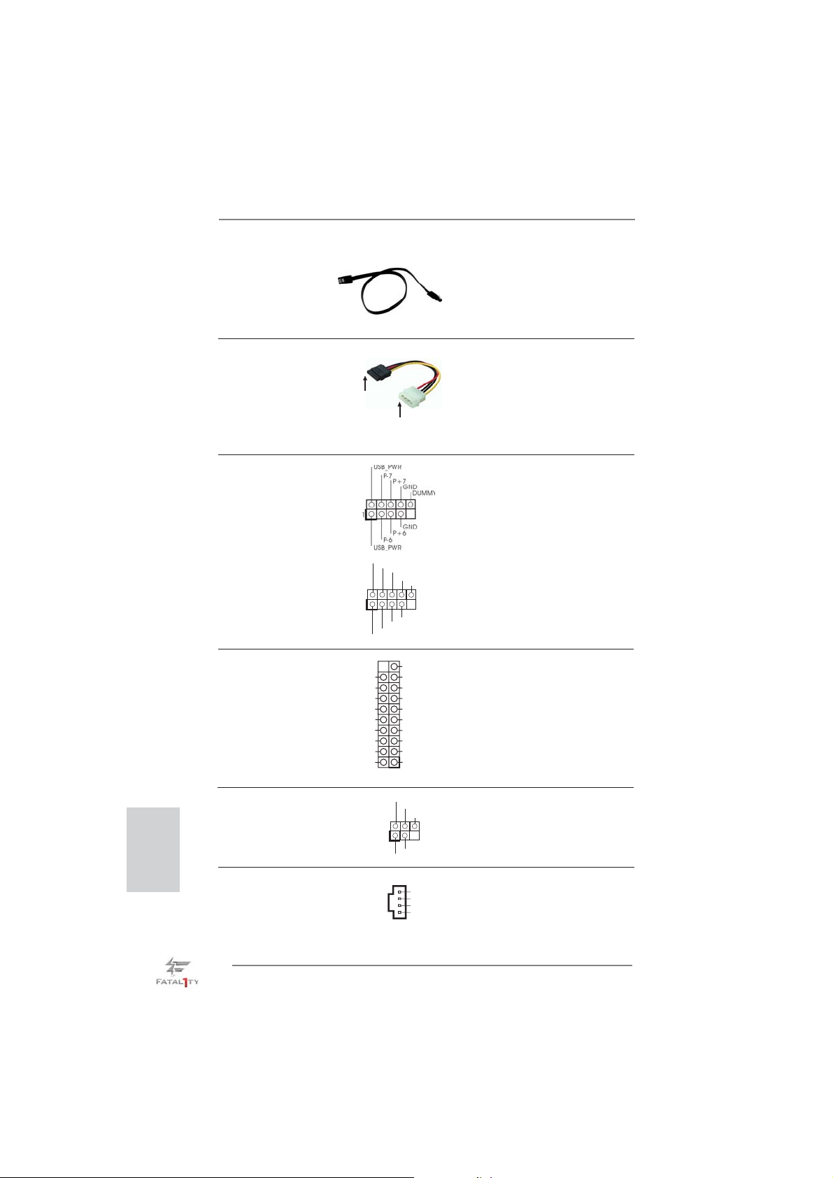
Serial ATA (SATA) Either end of the SATA data
Data Cable cable can be connected to the
(Optional)
SATA / SATA2 / SATA3 hard
disk or the SATA2 / SATA3
connector on this motherboard.
Serial ATA (SATA) Please connect the black end
Power Cable of SATA power cable to the
(Optional)
Then connect the white end of
SATA power cable to the power
connector of the power supply.
power connector on each drive.
connect to the SATA
HDD power connector
connect to the
power supply
USB 2.0 Headers Besides six default USB 2.0
(9-pin USB_6_7)
(see p.4, No. 24)
ports on the I/O panel, there are
two USB 2.0 headers on this
motherboard. Each USB 2.0
header can support two USB 2.0
(9-pin USB_8_9)
(see p.4, No. 25)
1
USB_PWR
P-9
P-8
USB_PWR
P+9
P+8
GND
GND
DUMMY
ports.
English
USB 3.0 Header Besides six default USB 3.0
(19-pin USB3_6_7)
(see p.4, No. 9)
ports on the I/O panel, there is
one USB 3.0 header on this
motherboard. This USB 3.0
header can support two USB 3.0
ports.
Vbus
IntA_P6_SSRX-
IntA_P6_SSRX+
GND
IntA_P6_SSTX-
IntA_P6_SSTX+
GND
IntA_P6_D-
IntA_P6_D+
Infrared Module Header This header supports an
(5-pin IR1)
optional wireless transmitting
(see p.4, No. 29)
and receiving infrared module.
IRTX
+5VSB
1
GND
IRRX
VbusVbus
IntA_P7_SSRX-
IntA_P7_SSRX+
GND
IntA_P7_SSTX-
IntA_P7_SSTX+
GND
IntA_P7_D-
IntA_P7_D+
DUMMY
DUMMY
Internal Audio Connectors This connector allows you
CD1
CD-L
GND
GND
CD- R
(4-pin CD1)
(CD1: see p.4 No. 42)
to receive stereo audio input
from sound sources such as
a CD-ROM, DVD-ROM, TV
tuner card, or MPEG card.
38
Fatal1ty Z77 Professional Series Motherboard
Page 39
1
GND
PRESENCE#
MIC2_R
MIC2_L
MIC_RET
J_SENSE
OUT2_R
OUT_RET
OUT2_L
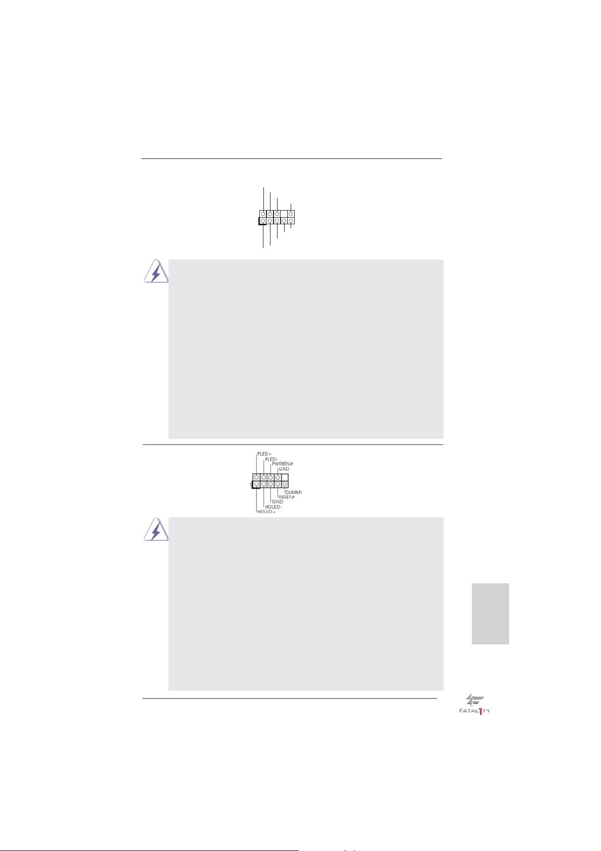
Front Panel Audio Header This is an interface for front
(9-pin HD_AUDIO1)
(see p.4, No. 32)
panel audio cable that allows
convenient connection and
control of audio devices.
1. High Defi nition Audio supports Jack Sensing, but the panel wire on the
chassis must support HDA to function correctly. Please follow the
instruction in our manual and chassis manual to install your system.
2. If you use AC’97 audio panel, please install it to the front panel audio
header as below:
A. Connect Mic_IN (MIC) to MIC2_L.
B. Connect Audio_R (RIN) to OUT2_R and Audio_L (LIN) to OUT2_L.
C. Connect Ground (GND) to Ground (GND).
D. MIC_RET and OUT_RET are for HD audio panel only. You don’t need
to connect them for AC’97 audio panel.
E. To activate the front mic.
For Windows
Select “Mixer”. Select “Recorder”. Then click “FrontMic”.
For Windows
®
XP / XP 64-bit OS:
®
7 / 7 64-bit / VistaTM / VistaTM 64-bit OS:
Go to the “FrontMic” Tab in the Realtek Control panel. Adjust
“Recording Volume”.
System Panel Header This header accommodates
(9-pin PANEL1)
(see p.4, No. 21)
several system front panel
functions.
Connect the power switch, reset switch and system status indicator on the
chassis to this header according to the pin assignments below. Note the
positive and negative pins before connecting the cables.
PWRBTN (Power Switch):
Connect to the power switch on the chassis front panel. You may confi gure
the way to turn off your system using the power switch.
RESET (Reset Switch):
Connect to the reset switch on the chassis front panel. Press the reset
switch to restart the computer if the computer freezes and fails to perform a
normal restart.
PLED (System Power LED):
Connect to the power status indicator on the chassis front panel. The LED
is on when the system is operating. The LED keeps blinking when the system is in S1/S3 sleep state. The LED is off when the system is in S4 sleep
state or powered off (S5).
Fatal1ty Z77 Professional Series Motherboard
English
39
Page 40
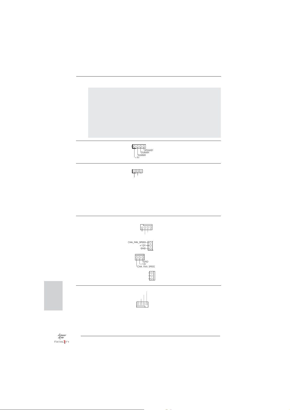
HDLED (Hard Drive Activity LED):
Connect to the hard drive activity LED on the chassis front panel. The LED
is on when the hard drive is reading or writing data.
The front panel design may differ by chassis. A front panel module mainly
consists of power switch, reset switch, power LED, hard drive activity LED,
speaker and etc. When connecting your chassis front panel module to this
header, make sure the wire assignments and the pin assign-ments are
matched correctly.
Chassis Speaker Header Please connect the chassis
(4-pin SPEAKER 1)
(see p.4, No. 20)
speaker to this header.
English
Power LED Header Please connect the chassis
(3-pin PLED1)
(see p.4, No. 19)
power LED to this header to
indicate system power status.
1
PLED+
PLED+
PLED-
The LED is on when the system
is operating. The LED keeps
blinking in S1/S3 state. The
LED is off in S4 state or S5
state (power off).
Chassis and Power Fan Connectors Please connect the fan cables
(4-pin CHA_FAN1)
(see p.4, No. 26)
CHA_FAN1, CHA_FAN2 and
(3-pin CHA_FAN2)
(see p.4, No. 43)
(3-pin CHA_FAN3)
(see p.4, No. 22)
(3-pin PWR_FAN1)
(see p.4, No. 41)
CPU Fan Connectors Please connect the CPU fan
(4-pin CPU_FAN1)
(see p.4, No. 3)
ground pin.
to the fan connectors and match
the black wire to the ground pin.
FAN_SPEED_CONTROL
CHA_FAN_SPEED
+12V
GND
CHA_FAN3 support Fan
Control.
PWR_FAN_SPEED
+12V
GND
FAN_SPEED_CONTROL
cable to the connector and
match the black wire to the
CPU_FAN_SPEED
+12V
GND
1 2 3 4
40
Fatal1ty Z77 Professional Series Motherboard
Page 41
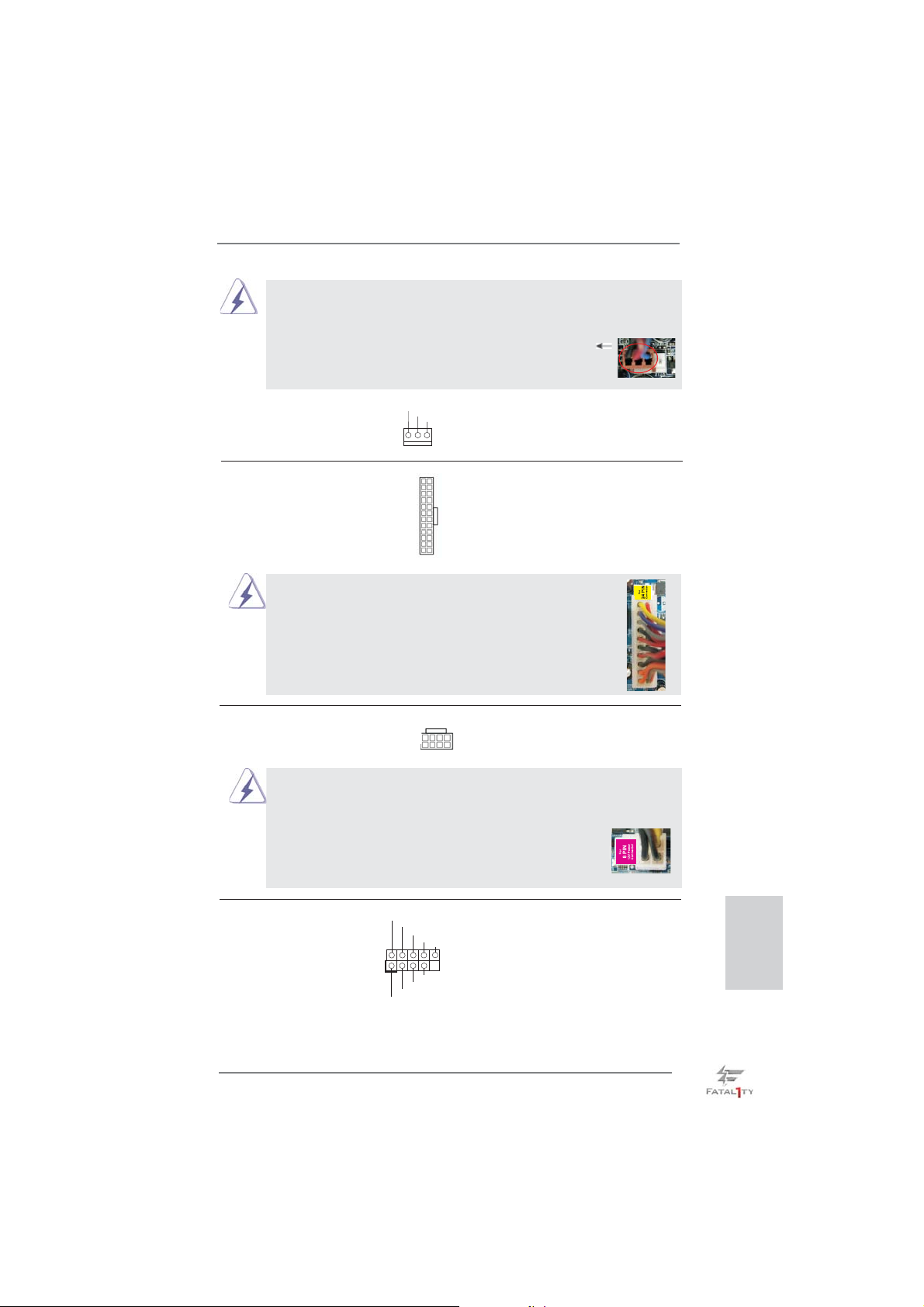
Though this motherboard provides 4-Pin CPU fan (Quiet Fan) support, the 3-Pin
CPU fan still can work successfully even without the fan speed control function.
If you plan to connect the 3-Pin CPU fan to the CPU fan connector on this
motherboard, please connect it to Pin 1-3.
Pin 1-3 Connected
3-Pin Fan Installation
(3-pin CPU_FAN2)
(see p.4, No. 4)
ATX Power Connector Please connect an ATX power
(24-pin ATXPWR1)
(see p.4, No. 7)
supply to this connector.
Though this motherboard provides 24-pin ATX power connector,
GND
+12V
12 124
CPU_FAN_SPEED
13
12
it can still work if you adopt a traditional 20-pin ATX power supply.
To use the 20-pin ATX power supply, please plug your
power supply along with Pin 1 and Pin 13.
20-Pin ATX Power Supply Installation
ATX 12V Power Connector Please connect an ATX 12V
(8-pin ATX12V1)
(see p.4, No. 2)
power supply to this connector.
8 5
4 1
1
Though this motherboard provides 8-pin ATX 12V power connector, it can still work
if you adopt a traditional 4-pin ATX 12V power supply. To use the 4-pin ATX power
supply, please plug your power supply along with Pin 1 and Pin 5.
8 5
24
13
4-Pin ATX 12V Power Supply Installation
IEEE 1394 Header Besides one default IEEE 1394
(9-pin FRONT_1394)
(see p.4 No. 28)
port on the I/O panel, there
is one IEEE 1394 header
(FRONT_1394) on this
motherboard. This IEEE 1394
header can support one IEEE
RXTPAM_0
1
RXTPAP_0
GND
GND
RXTPBM_0
+12V
+12V
RXTPBP_0
GND
4 1
1394 port.
Fatal1ty Z77 Professional Series Motherboard
English
41
Page 42
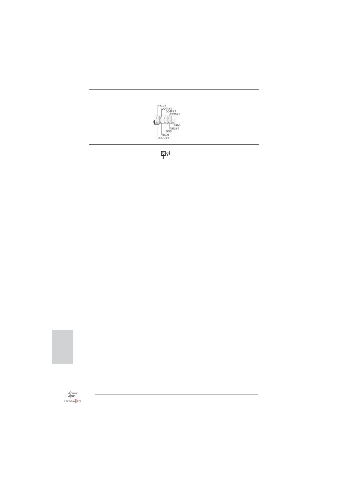
Serial port Header This COM1 header supports a
(9-pin COM1)
(see p.4, No. 31)
serial port module.
HDMI_SPDIF Header HDMI_SPDIF header, providing
(2-pin HDMI_SPDIF1)
(see p.4, No. 33)
SPDIF audio output to HDMI
VGA card, allows the system to
1
GND
SPDIFOUT
connect HDMI Digital TV/
projector/LCD devices. Please
connect the HDMI_SPDIF
connector of HDMI VGA card to
this header.
English
42
Fatal1ty Z77 Professional Series Motherboard
Page 43
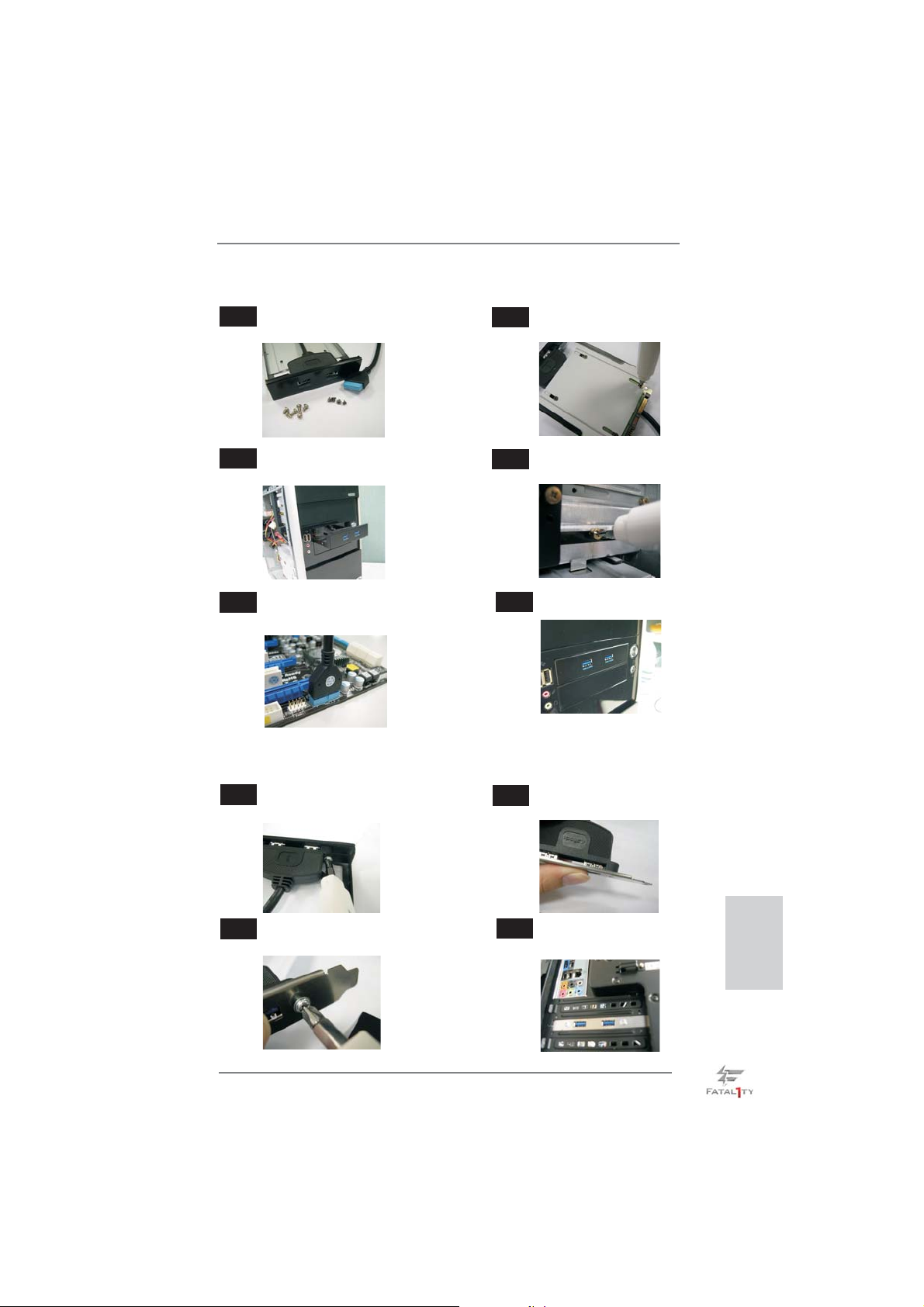
The Installation Guide of Front USB 3.0 Panel
Step 1
Prepare the bundled Front USB 3.0 Panel, four
HDD screws, and six chassis screws.
Step 2
Screw the 2.5” HDD/SSD to the Front
USB 3.0 Panel with four HDD screws.
Step 3
Intall the Front USB 3.0 Panel into the 2.5”
drive bay of the chassis.
Step 5
Plug the Front USB 3.0 cable into the USB 3.0
header (USB3_6_7) on the motherboard.
Step 4
Step 6
The Installation Guide of Rear USB 3.0 Bracket
Step 1
Unscrew the two screws from the Front USB 3.0
Panel.
Step 2
Screw the Front USB 3.0 Panel to the
drive bay with six chassis screws.
The Front USB 3.0 Panel is ready to use.
Put the USB 3.0 cable and the rear
USB 3.0 bracket together.
Step 3
Screw the two screws into the rear USB 3.0
bracket.
Fatal1ty Z77 Professional Series Motherboard
Step 4
Put the rear USB 3.0 bracket into the
chassis.
English
43
Page 44
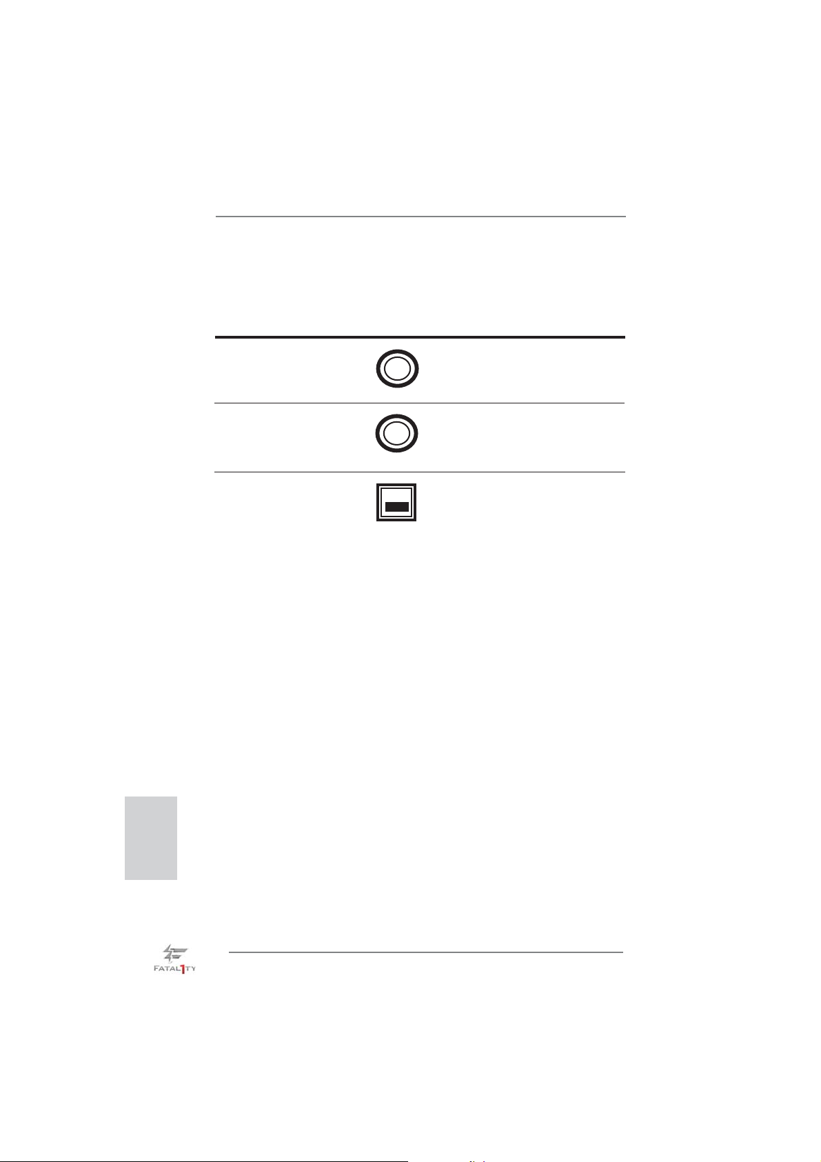
2.12 Smart Switches
The motherboard has three smart switches: power switch, reset switch and clear
CMOS switch, allowing users to quickly turn on/off or reset the sytem clear the
CMOS values.
Power Switch Power Switch is a smart switch,
(PWRBTN)
(see p.4 No. 16)
Reset Switch Reset Switch is a smart switch,
(RSTBTN)
(see p.4 No. 17)
Clear CMOS Switch Clear CMOS Switch is a smart
(CLRCBTN)
(see p.5 No. 18)
allowing users to quickly turn
Power
on/off the system.
allowing users to quickly reset
Reset
the system.
switch, allowing users to quickly
clear the CMOS values.
clr
CMOS
English
44
Fatal1ty Z77 Professional Series Motherboard
Page 45
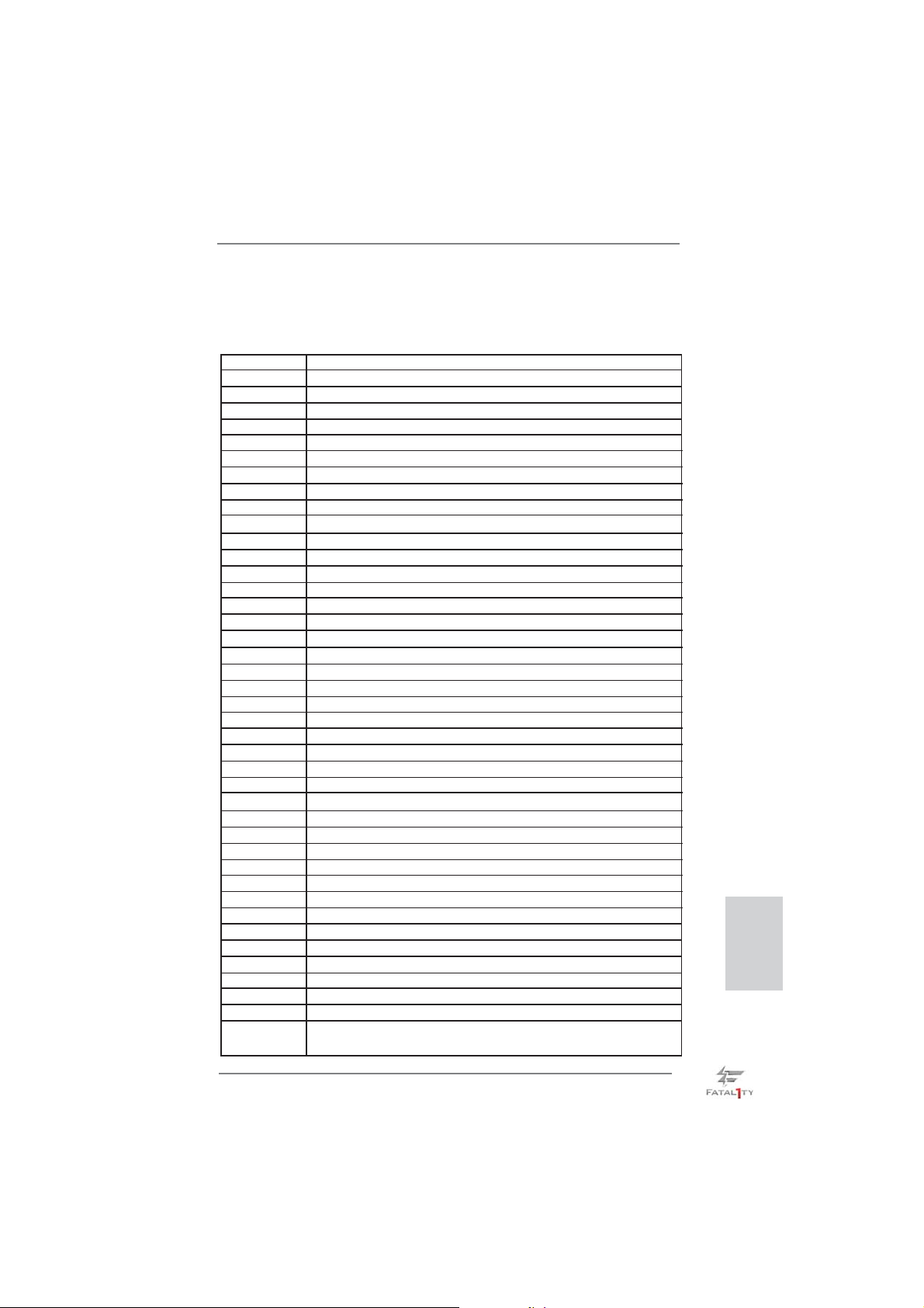
2.13 Dr. Debug
Dr. Debug is used to provide code information, which makes troubleshooting even
easier. Please see the diagrams below for reading the Dr. Debug codes.
Status Code Description
0x00 Not used
0x01 Power on. Reset type detection (soft/hard)
0x02 AP initialization before microcode loading
0x03 North Bridge initialization before microcode loading
0x04 South Bridge initialization before microcode loading
0x05 OEM initialization before microcode loading
0x06 Microcode loading
0x07 AP initialization after microcode loading
0x08 North Bridge initialization after microcode loading
0x09 South Bridge initialization after microcode loading
0x0A OEM initialization after microcode loading
0x0B Cache initialization
0x0C – 0x0D Reserved for future AMI SEC error codes
0x0E Microcode not found
0x0F Microcode not loaded
0x10 PEI Core is started
0x11 Pre-memory CPU initialization is started
0x12 Pre-memory CPU initialization (CPU module specifi c)
0x13 Pre-memory CPU initialization (CPU module specifi c)
0x14 Pre-memory CPU initialization (CPU module specifi c)
0x15 Pre-memory North Bridge initialization is started
0x16 Pre-Memory North Bridge initialization (North Bridge module specifi c)
0x17 Pre-Memory North Bridge initialization (North Bridge module specifi c)
0x18 Pre-Memory North Bridge initialization (North Bridge module specifi c)
0x19 Pre-memory South Bridge initialization is started
0x1A Pre-memory South Bridge initialization (South Bridge module specifi c)
0x1B Pre-memory South Bridge initialization (South Bridge module specifi c)
0x1C Pre-memory South Bridge initialization (South Bridge module specifi c)
0x1D – 0x2A OEM pre-memory initialization codes
0x2B Memory initialization. Serial Presence Detect (SPD) data reading
0x2C Memory initialization. Memory presence detection
0x2D Memory initialization. Programming memory timing information
0x2E Memory initialization. Confi guring memory
0x2F Memory initialization (other)
0x30 Reserved for ASL
0x31 Memory Installed
0x32 CPU post-memory initialization is started
0x33 CPU post-memory initialization. Cache initialization
0x34 CPU post-memory initialization. Application Processor(s) (AP) initialization
0x35 CPU post-memory initialization. Boot Strap Processor (BSP) selection
0x36 CPU post-memory initialization. System Management Mode (SMM)
initialization
Fatal1ty Z77 Professional Series Motherboard
English
45
Page 46
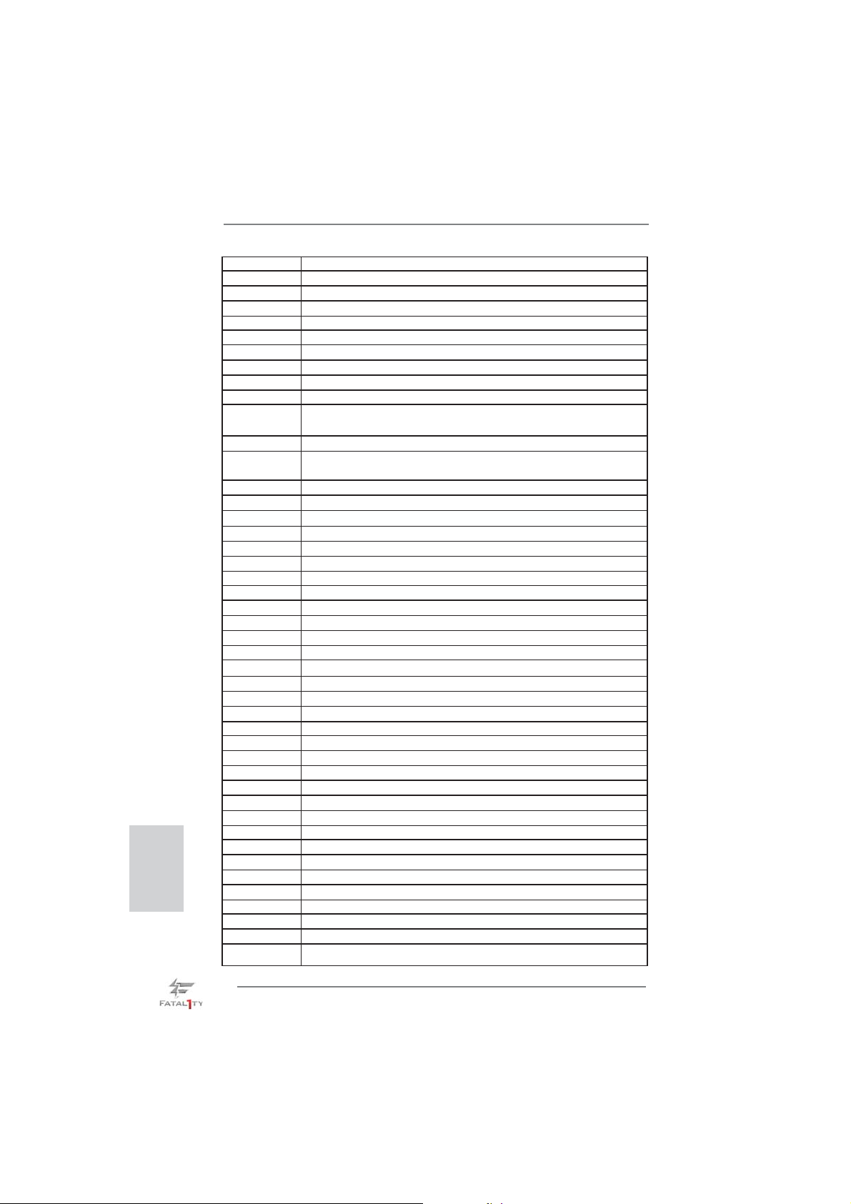
English
0x37 Post-Memory North Bridge initialization is started
0x38 Post-Memory North Bridge initialization (North Bridge module specifi c)
0x39 Post-Memory North Bridge initialization (North Bridge module specifi c)
0x3A Post-Memory North Bridge initialization (North Bridge module specifi c)
0x3B Post-Memory South Bridge initialization is started
0x3C Post-Memory South Bridge initialization (South Bridge module specifi c)
0x3D Post-Memory South Bridge initialization (South Bridge module specifi c)
0x3E Post-Memory South Bridge initialization (South Bridge module specifi c)
0x3F-0x4E OEM post memory initialization codes
0x4F DXE IPL is started
0x50 Memory initialization error. Invalid memory type or incompatible memory
speed
0x51 Memory initialization error. SPD reading has failed
0x52 Memory initialization error. Invalid memory size or memory modules do not
match
0x53 Memory initialization error. No usable memory detected
0x54 Unspecifi ed memory initialization error
0x55 Memory not installed
0x56 Invalid CPU type or Speed
0x57 CPU mismatch
0x58 CPU self test failed or possible CPU cache error
0x59 CPU micro-code is not found or micro-code update is failed
0x5A Internal CPU error
0x5B reset PPI is not available
0x5C-0x5F Reserved for future AMI error codes
0xE0 S3 Resume is stared (S3 Resume PPI is called by the DXE IPL)
0xE1 S3 Boot Script execution
0xE2 Video repost
0xE3 OS S3 wake vector call
0xE4-0xE7 Reserved for future AMI progress codes
0xE8 S3 Resume Failed
0xE9 S3 Resume PPI not Found
0xEA S3 Resume Boot Script Error
0xEB S3 OS Wake Error
0xEC-0xEF Reserved for future AMI error codes
0xF0 Recovery condition triggered by fi rmware (Auto recovery)
0xF1 Recovery condition triggered by user (Forced recovery)
0xF2 Recovery process started
0xF3 Recovery fi rmware image is found
0xF4 Recovery fi rmware image is loaded
0xF5-0xF7 Reserved for future AMI progress codes
0xF8 Recovery PPI is not available
0xF9 Recovery capsule is not found
0xFA Invalid recovery capsule
0xFB – 0xFF Reserved for future AMI error codes
0x60 DXE Core is started
0x61 NVRAM initialization
46
Fatal1ty Z77 Professional Series Motherboard
Page 47
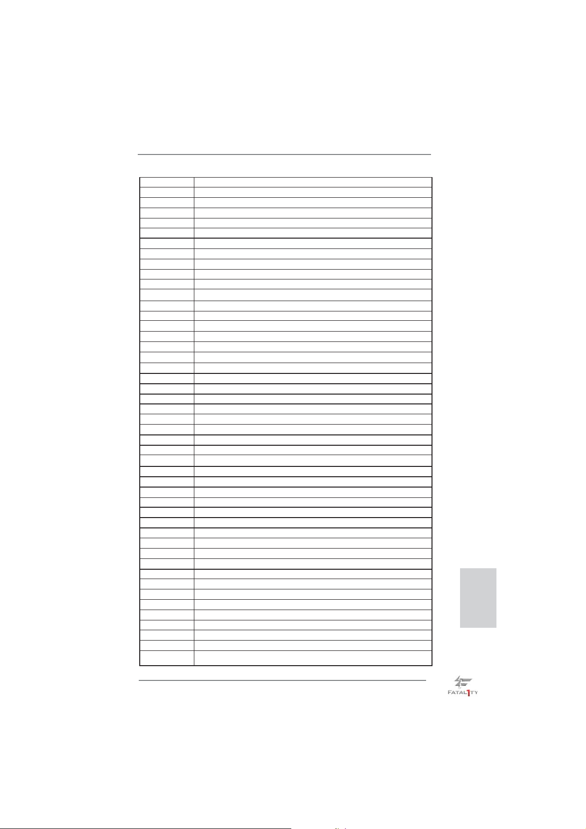
0x62 Installation of the South Bridge Runtime Services
0x63 CPU DXE initialization is started
0x64 CPU DXE initialization (CPU module specifi c)
0x65 CPU DXE initialization (CPU module specifi c)
0x66 CPU DXE initialization (CPU module specifi c)
0x67 CPU DXE initialization (CPU module specifi c)
0x68 PCI host bridge initialization
0x69 North Bridge DXE initialization is started
0x6A North Bridge DXE SMM initialization is started
0x6B North Bridge DXE initialization (North Bridge module specifi c)
0x6C North Bridge DXE initialization (North Bridge module specifi c)
0x6D North Bridge DXE initialization (North Bridge module specifi c)
0x6E North Bridge DXE initialization (North Bridge module specifi c)
0x6F North Bridge DXE initialization (North Bridge module specifi c)
0x70 South Bridge DXE initialization is started
0x71 South Bridge DXE SMM initialization is started
0x72 South Bridge devices initialization
0x73 South Bridge DXE Initialization (South Bridge module specifi c)
0x74 South Bridge DXE Initialization (South Bridge module specifi c)
0x75 South Bridge DXE Initialization (South Bridge module specifi c)
0x76 South Bridge DXE Initialization (South Bridge module specifi c)
0x77 South Bridge DXE Initialization (South Bridge module specifi c)
0x78 ACPI module initialization
0x79 CSM initialization
0x7A – 0x7F Reserved for future AMI DXE codes
0x80 – 0x8F OEM DXE initialization codes
0x90 Boot Device Selection (BDS) phase is started
0x91 Driver connecting is started
0x92 PCI Bus initialization is started
0x93 PCI Bus Hot Plug Controller Initialization
0x94 PCI Bus Enumeration
0x95 PCI Bus Request Resources
0x96 PCI Bus Assign Resources
0x97 Console Output devices connect
0x98 Console input devices connect
0x99 Super IO Initialization
0x9A USB initialization is started
0x9B USB Reset
0x9C USB Detect
0x9D USB Enable
0x9E – 0x9F Reserved for future AMI codes
0xA0 IDE initialization is started
0xA1 IDE Reset
0xA2 IDE Detect
0xA3 IDE Enable
0xA4 SCSI initialization is started
0xA5 SCSI Reset
English
Fatal1ty Z77 Professional Series Motherboard
47
Page 48
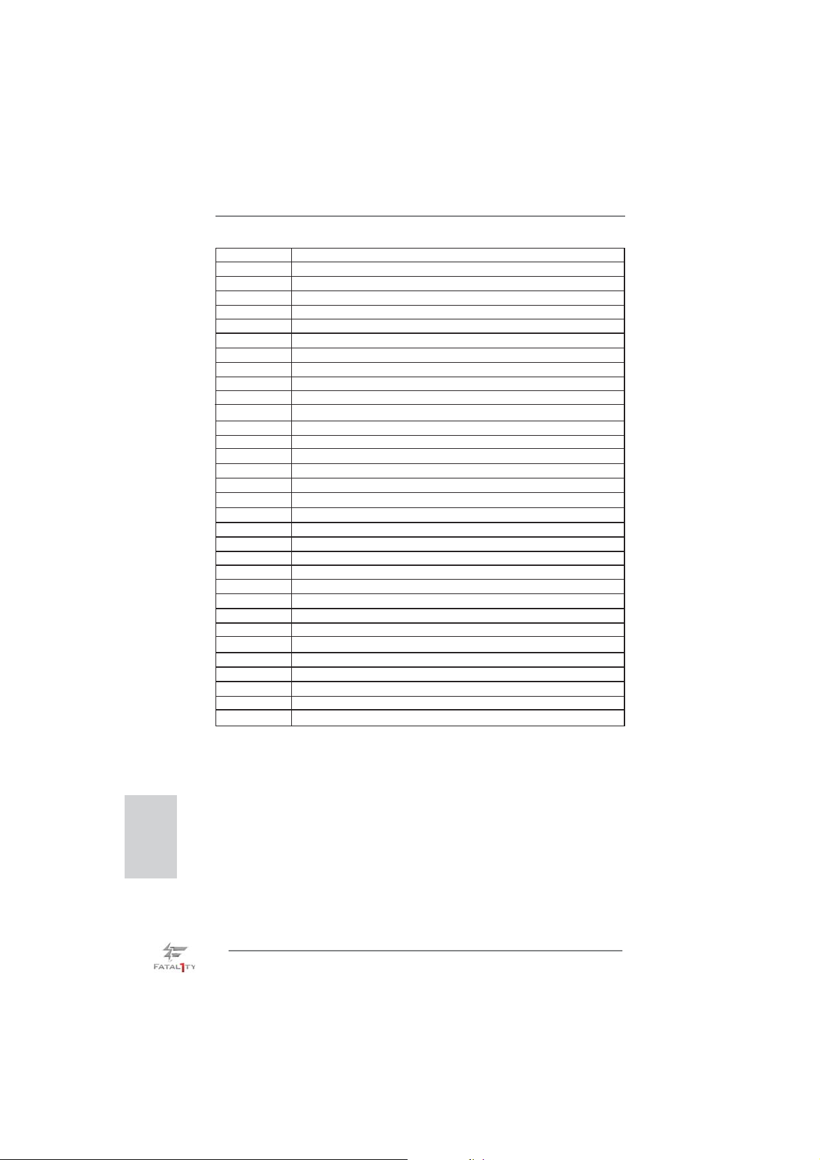
0xA6 SCSI Detect
0xA7 SCSI Enable
0xA8 Setup Verifying Password
0xA9 Start of Setup
0xAA Reserved for ASL (see ASL Status Codes section below)
0xAB Setup Input Wait
0xAC Reserved for ASL (see ASL Status Codes section below)
0xAD Ready To Boot event
0xAE Legacy Boot event
0xAF Exit Boot Services event
0xB0 Runtime Set Virtual Address MAP Begin
0xB1 Runtime Set Virtual Address MAP End
0xB2 Legacy Option ROM Initialization
0xB3 System Reset
0xB4 USB hot plug
0xB5 PCI bus hot plug
0xB6 Clean-up of NVRAM
0xB7 Confi guration Reset (reset of NVRAM settings)
0xB8 – 0xBF Reserved for future AMI codes
0xC0 – 0xCF OEM BDS initialization codes
0xD0 CPU initialization error
0xD1 North Bridge initialization error
0xD2 South Bridge initialization error
0xD3 Some of the Architectural Protocols are not available
0xD4 PCI resource allocation error. Out of Resources
0xD5 No Space for Legacy Option ROM
0xD6 No Console Output Devices are found
0xD7 No Console Input Devices are found
0xD8 Invalid password
0xD9 Error loading Boot Option (LoadImage returned error)
0xDA Boot Option is failed (StartImage returned error)
0xDB Flash update is failed
0xDC Reset protocol is not available
English
48
Fatal1ty Z77 Professional Series Motherboard
Page 49

2.14 Driver Installation Guide
To install the drivers to your system, please insert the support CD to your optical
drive fi rst. Then, the drivers compatible to your system can be auto-detected and
listed on the support CD driver page. Please follow the order from up to bottom side
to install those required drivers. Therefore, the drivers you install can work properly.
2.15 Installing Windows® 7 / 7 64-bit / Vista
TM
/ VistaTM 64-bit / XP /
XP 64-bit With RAID Functions
If you want to install Windows® 7 / 7 64-bit / VistaTM / VistaTM 64-bit / XP / XP 64bit on your SATA / SATA2 / SATA3 HDDs with RAID functions, please refer to the
document at the following path in the Support CD for detailed procedures:
..\ RAID Installation Guide
2.16 Installing Windows® 7 / 7 64-bit / Vista
TM
/ Vista
TM
64-bit / XP /
XP 64-bit Without RAID Functions
If you want to install Windows® 7 / 7 64-bit / VistaTM / VistaTM 64-bit / XP / XP 64bit OS on your SATA / SATA2 / SATA3 HDDs without RAID functions, please follow
below procedures according to the OS you install.
2.16.1 Installing Windows® XP / XP 64-bit Without RAID Functions
If you want to install Windows® XP / XP 64-bit OS on your SATA / SATA2 / SATA3
HDDs without RAID functions, please follow below steps.
Using SATA / SATA2 / SATA3 HDDs without NCQ function
STEP 1: Set Up UEFI.
A. Enter UEFI SETUP UTILITY Advanced screen Storage Confi guration.
B. Set the option “SATA Mode Selection” to [IDE] for SATA2_2 to SATA2_5 and
SATA3_0 and SATA3_1 ports.
Set the option “ASMedia SATA3 Mode” to [IDE] for SATA3_A1 to SATA2_A4
ports.
STEP 2: Install Windows
®
XP / XP 64-bit OS on your system.
Fatal1ty Z77 Professional Series Motherboard
English
49
Page 50

2.16.2 Installing Windows® 7 / 7 64-bit / Vista
TM
/ Vista
TM
64-bit
Without RAID Functions
If you want to install Windows® 7 / 7 64-bit / VistaTM / VistaTM 64-bit OS on your SATA
/ SATA2 / SATA3 HDDs without RAID functions, please follow below steps.
Using SATA / SATA2 / SATA3 HDDs without NCQ function
STEP 1: Set Up UEFI.
A. Enter UEFI SETUP UTILITY Advanced screen Storage Confi guration.
B. Set the option “SATA Mode Selection” to [IDE] for SATA2_2 to SATA2_5 and
SATA3_0 and SATA3_1 ports.
Set the option “ASMedia SATA3 Mode” to [IDE] for SATA3_A1 to SATA2_A4
ports.
STEP 2: Install Windows
Using SATA / SATA2 / SATA3 HDDs with NCQ function
STEP 1: Set Up UEFI.
A. Enter UEFI SETUP UTILITY Advanced screen Storage Confi guration.
B. Set the option “SATA Mode Selection” to [AHCI] for SATA2_2 to SATA2_5 and
SATA3_0 and SATA3_1 ports.
Set the option “ASMedia SATA3 Mode” to [AHCI] for SATA3_A1 to SATA2_A4
ports.
STEP 2: Install Windows
®
XP / XP 64-bit OS on your system.
®
XP / XP 64-bit OS on your system.
English
50
Fatal1ty Z77 Professional Series Motherboard
Page 51

2.17 Teaming Function Operation Guide
Dual LAN with Teaming function enabled on this motherboard allows two single
connections to act as one single connection for twice the transmission bandwidth,
making data transmission more effective and improving the quality of transmission
of distant images. Fault tolerance on the dual LAN network prevents network
downtime by transferring the workload from a failed port to a working port.
The speed of transmission is subject to the actual network environment
or status even with Teaming enabled.
Before setting up Teaming function, please make sure if your Switch (or Router)
could support Teaming (IEEE 802.3ad Link Aggregation) function. Then, please
refer to following steps to set up Teaming function.
1. Install Teaming driver from the following path of motherboard Support CD:
32-bit:
64-bit: .. \Drivers\LAN\Broadcom\Teaming\x64
(This is a special driver for Teaming function only. If you don't want to use
Teaming, please install the LAN driver provided by our support CD link.)
2. From the Teams menu, select Create Team, or right-click one of the devices in
the “Unassigned Adapters” section and select Create a Team. This option is not
available if there are no devices listed in the “Unassigned Adapters” sections,
which means all adapters are already assigned to teams.
.. \Drivers\LAN\Broadcom\Teaming\IA32
3. Click Expert Mode.
* If you want to always use Expert Mode to create a team, click Default to Expert
Mode on next start.
Fatal1ty Z77 Professional Series Motherboard
English
51
Page 52
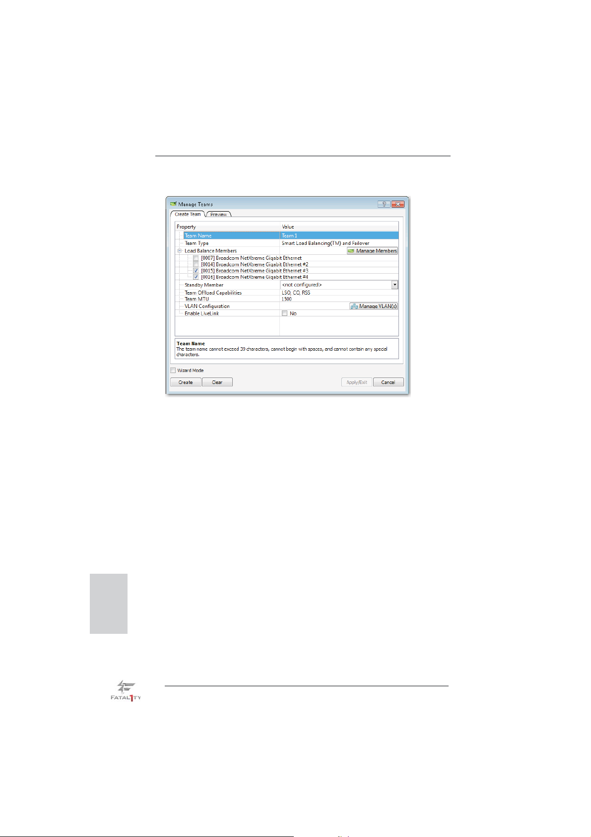
4. Click the Create Team tab.
* The Create Team tab appears only if there are teamable adapters available.
5. Click the Team Name fi eld to enter a team name.
6. Click the Team Type fi eld to select a team type.
English
7. Assign any available adapter or adapters to the team by selecting the adapter
from the Load Balance Members list. There must be at least one adapter
selected in the Load Balance Members list.
8. You can assign any other available adapter to be a standby member by selecting
it from the Standby Member list.
* There must be at least one Broadcom network adapter assigned to the team.
The Large Send Offl oad (LSO), Checksum Offl oad (CO), and RSS indicate if
the LSO, CO, and/or RSS properties are supported for the team. The LSO, CO,
and RSS properties are enabled for a team only when all of the members
support and are confi gured for the feature.
* Adding a network adapter to a team where its driver is disabled may negatively
affect the offl oading capabilities of the team. This may have an impact on the
team’s performance. Therefore, it is recommended that only driver-enabled
network adapters be added as members to a team.
52
Fatal1ty Z77 Professional Series Motherboard
Page 53

9. Type the value for Team MTU.
10. Click Create to save the team information.
11. Repeat steps 5. through 10. to defi ne additional teams. As teams are defi ned,
they can be selected from the team list, but they have not yet been created.
Click the Preview tab to view the team structure before applying the changes.
12. Click Apply/Exit to create all the teams you have defi ned and exit the Manage
Teams window.
13. Click Yes when the message is displayed indicating that the network connection
will be temporarily interrupted.
* The team name cannot exceed 39 characters, cannot begin with spaces, and
cannot contain any of the following characters: & \ / : * ? < > |
* Team names must be unique. If you attempt to use a team name more than
once, an error message is displayed indicating that the name already exists.
* The maximum number of team members is 8.
* When team confi guration has been correctly performed, a virtual team adapter
driver is created for each confi gured team.
* If you disable a virtual team and later want to reenable it, you must fi rst disable
and reenable all team members before you reenable the virtual team.
* When you create Generic Trunking and Link Aggregation teams, you cannot
designate a standby member. Standby members work only with Smart Load
Balancing and Failover and SLB (Auto-Fallback Disable) types of teams.
* For an SLB (Auto-Fallback Disable) team, to restore traffi c to the load
balance members from the standby member, click the Fallback button on the
Team Properties tab.
* When confi guring an SLB team, although connecting team members to a hub
is supported for testing, it is recommended to connect team members to a
switch.
* Not all network adapters made by others are supported or fully certifi ed for
teaming.
Fatal1ty Z77 Professional Series Motherboard
English
53
Page 54

14. Confi gure the team IP address.
a. From Control Panel, double-click Network Connections.
b. Right-click the name of the team to be confi gured, and then click Properties.
c. On the General tab, click Internet Protocol (TCP/IP), and then click
Properties.
d. Confi gure the IP address and any other necessary TCP/IP confi guration for
the team, and then click OK when fi nished.
English
54
Fatal1ty Z77 Professional Series Motherboard
Page 55

3. BIOS Information
The Flash Memory on the motherboard stores BIOS Setup Utility. When you start up
the computer, please press <F2> or <Del> during the Power-On-Self-Test (POST)
to enter BIOS Setup utility; otherwise, POST continues with its test routines. If you
wish to enter BIOS Setup after POST, please restart the system by pressing <Ctl>
+ <Alt> + <Delete>, or pressing the reset button on the system chassis. The BIOS
Setup program is designed to be user-friendly. It is a menu-driven program, which
allows you to scroll through its various sub-menus and to select among the predetermined choices. For the detailed information about BIOS Setup, please refer to the
User Manual (PDF fi le) contained in the Support CD.
4. Software Support CD information
®
This motherboard supports various Microsoft
64-bit / VistaTM / Vista
motherboard contains necessary drivers and useful utilities that will enhance motherboard features. To begin using the Support CD, insert the CD into your CD-ROM
drive. It will display the Main Menu automatically if “AUTORUN” is enabled in your
computer. If the Main Menu does not appear automatically, locate and double-click
on the fi le “ASSETUP.EXE” from the BIN folder in the Support CD to display the
menus.
TM
64-bit / XP / XP 64-bit. The Support CD that came with the
Windows® operating systems: 7 / 7
Fatal1ty Z77 Professional Series Motherboard
English
55
Page 56

Deutsch
1. Einführung
Wir danken Ihnen für den Kauf des ASRock Fatal1ty Z77 Professional Series
Motherboard, ein zuverlässiges Produkt, welches unter den ständigen, strengen
Qualitätskontrollen von ASRock gefertigt wurde. Es bietet Ihnen exzellente Leistung und robustes Design, gemäß der Verpfl ichtung von ASRock zu Qualität und
Halbarkeit. Diese Schnellinstallationsanleitung führt in das Motherboard und die
schrittweise Installation ein. Details über das Motherboard fi nden Sie in der Bedien-
ungsanleitung auf der Support-CD.
Da sich Motherboard-Spezifi kationen und BIOS-Software verändern können,
kann der Inhalt dieses Handbuches ebenfalls jederzeit geändert werden. Für
den Fall, dass sich Änderungen an diesem Handbuch ergeben, wird eine neue
Version auf der ASRock-Website, ohne weitere Ankündigung, verfügbar sein.
Die neuesten Grafi kkarten und unterstützten CPUs sind auch auf der ASRock-
Website aufgelistet.
ASRock-Website: http://www.asrock.com
Wenn Sie technische Unterstützung zu Ihrem Motherboard oder spezifi sche
Informationen zu Ihrem Modell benötigen, besuchen Sie bitte unsere Webseite:
www.asrock.com/support/index.asp
1.1 Kartoninhalt
ASRock Fatal1ty Z77 Professional Series Motherboard
(ATX-Formfaktor: 30.5 cm x 24.4 cm; 12.0 Zoll x 9.6 Zoll)
ASRock Fatal1ty Z77 Professional Series Schnellinstallationsanleitung
ASRock Fatal1ty Z77 Professional Series Support-CD
Sechs Serial ATA (SATA) -Datenkabel (optional)
Zwei Serial ATA (SATA) -Festplattenstromkabel (optional)
Ein I/O Shield
Ein USB 3.0-Frontblende
Vier Festplatte Schrauben
Sechs Gehäuses Schrauben
Ein USB 3.0-Blech an der Rückwand
Ein ASRock SLI_Bridge_2S-Karte
ASRock erinnert...
Zur besseren Leistung unter Windows® 7 / 7, 64 Bit / Vista
64 Bit empfehlen wir, die Speicherkonfi guration im BIOS auf den AHCI-
Modus einzustellen. Hinweise zu den BIOS-Einstellungen fi nden Sie in
der Bedienungsanleitung auf der mitgelieferten CD.
TM
/ VistaTM
56
Fatal1ty Z77 Professional Series Motherboard
Page 57
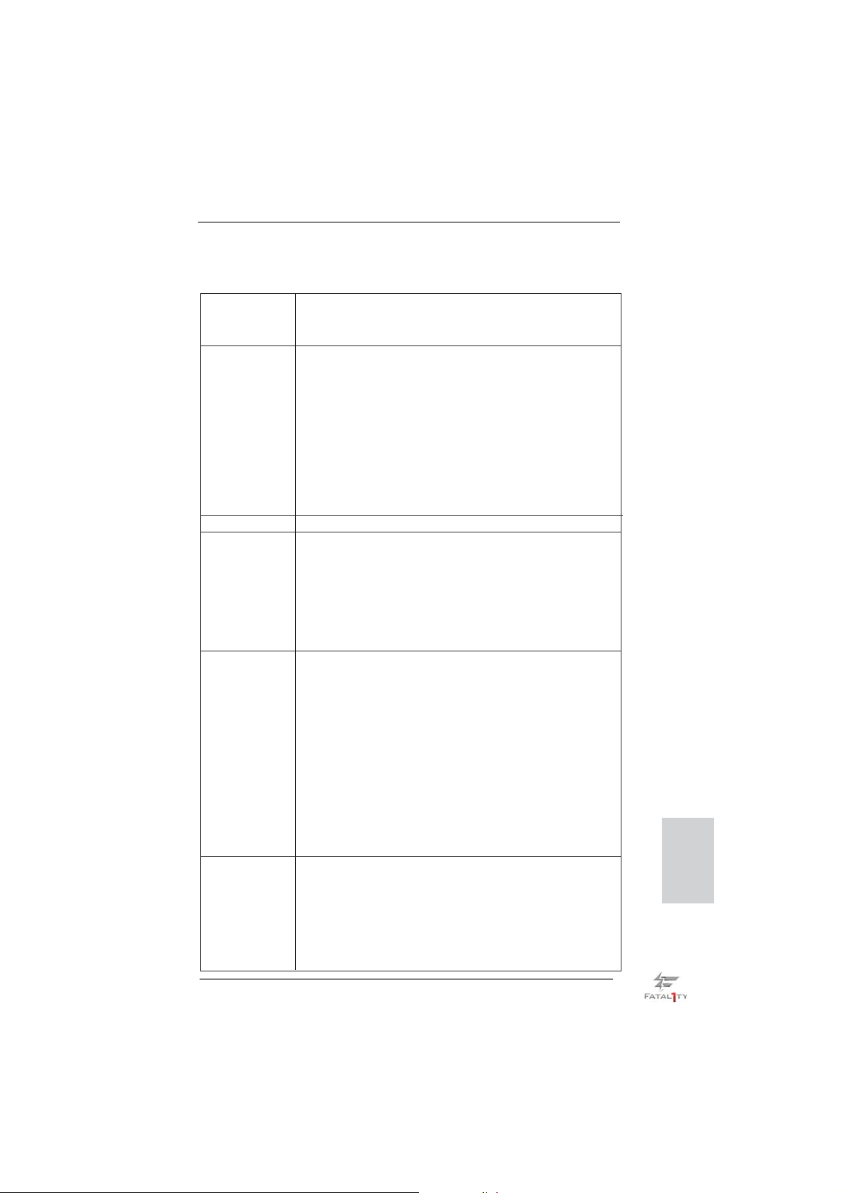
1.2 Spezifikationen
Plattform - ATX-Formfaktor: 30.5 cm x 24.4 cm; 12.0 Zoll x 9.6 Zoll
- Hochwertiges Gold-Kondensatordesign (100 % hochwertige
japanische Fertigung leitfähiger Polymerkondensatoren)
CPU - Unterstützt Intel
und 2ten Generation im LGA1155-Package
- Digi Power-Design
- 16 + 8-Stromphasendesign
- Unterstützt Intel
- Unterstützt freigegebene CPU der K-Serie
- Unterstützt Hyper-Threading-Technologie
(siehe VORSICHT 1)
- Unterstützt Intel® Rapid Start Technology und Smart
Connect Technology mit Intel
Chipsatz - Intel® Z77
Speicher - Dual-Kanal DDR3 Speichertechnologie (siehe VORSICHT 2)
- 4 x Steckplätze für DDR3
- Unterstützt DDR3 2800+(OC)/2400(OC)/2133(OC)/1866
(OC)/1600/1333/1066 non-ECC, ungepufferter Speicher
- Max. Kapazität des Systemspeichers: 32GB
(siehe VORSICHT 3)
- Unterstützt Intel
Erweiterungs- - 2 x PCI Express 3.0 x16-Steckplätze (PCIE2/PCIE4: Einzeln
steckplätze bei x16 (PCIE2) / x8 (PCIE4) oder dual im x8/x8-Modus)
(siehe VORSICHT 4)
* PCIE 3.0 wird nur mit Intel
unterstützt. Mit Intel® Sandy Bridge-Prozessor wird nur
PCIE 2.0 unterstützt.
- 1 x PCI Express 2.0 x16-Steckplätze (PCIE5:x4-Modus)
- 2 x PCI Express 2.0 x1-Steckplätze
- 2 x PCI-Steckplätze
- Unterstützt AMD
und CrossFireX
- NVIDIA® Quad SLITM und SLI
Onboard-VGA * Integrierte Intel® HD-Grafi kdarstellungen und die VGA-
Ausgänge können nur durch GPU-integrierte Prozessoren
unterstützt werden.
- Unterstützt hochaufl ösende integrierte Intel®-Grafi klösungen:
Intel
®
Quick-Sync-Video, Intel® InTruTM 3D, Intel® Clear Video-Technik (HD), Intel® HD Graphics 2500/4000, Intel®
Advanced Vector Extensions (AVX)
Fatal1ty Z77 Professional Series Motherboard
®
CoreTM i7- / i5- / i3-Prozessoren der 3ten
®
Turbo Boost 2.0-Technologie
®
Ivy Bridge-Prozessor
®
Extreme Memory Profi le (XMP)1.3/1.2
®
Ivy Bridge-Prozessor
TM
Quad CrossFireXTM, 3-Way CrossFireX
TM
TM
TM
Deutsch
57
Page 58
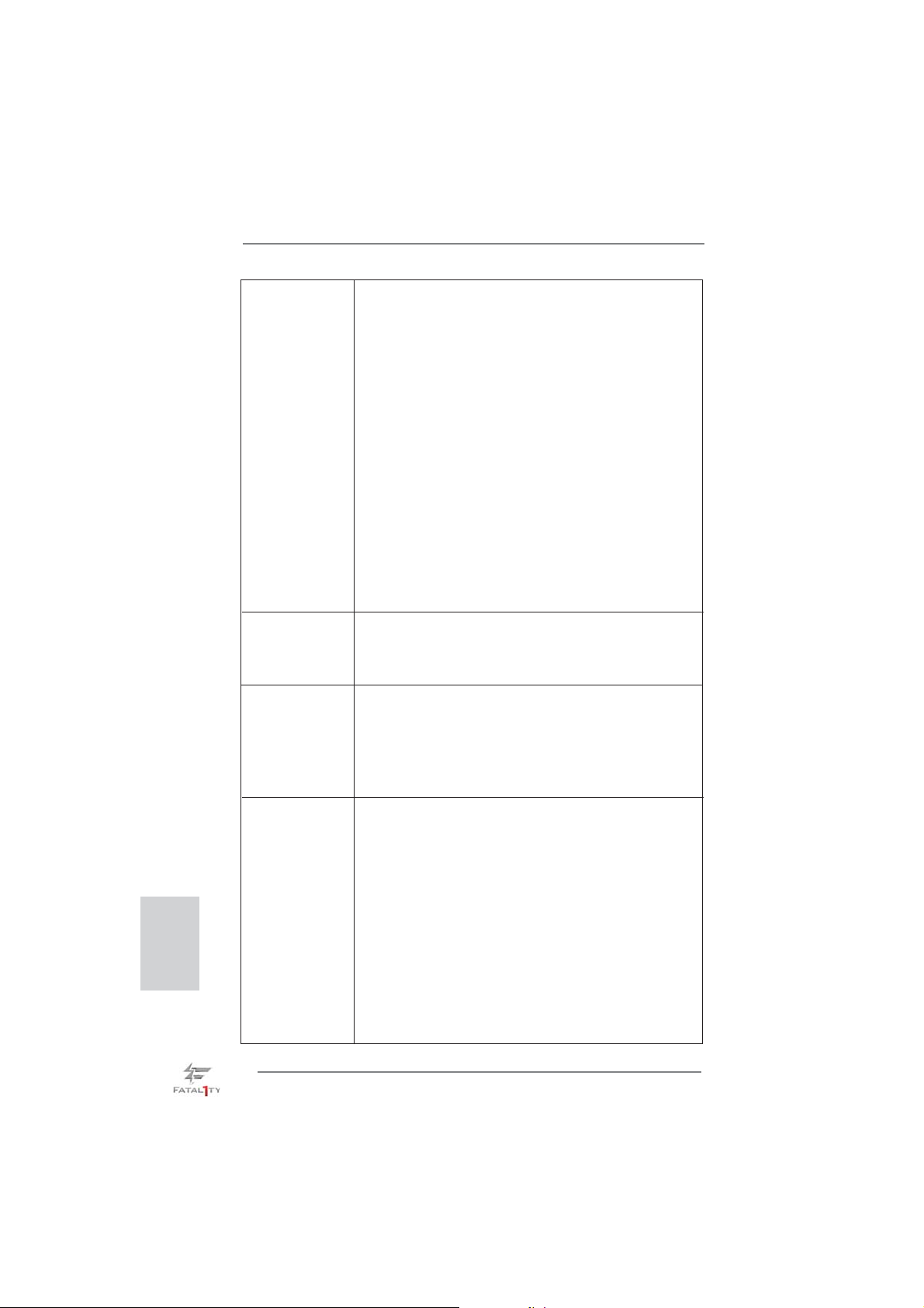
Deutsch
- Pixel Shader 5.0, DirectX 11 mit Intel® Ivy Bridge-Prozessor,
Pixel Shader 4.1, DirectX 10.1 mit Intel® Sandy Bridge Prozessor
- Maximal gemeinsam genutzter Speicher 1760MB
(siehe VORSICHT 5)
- Doppel-VGA Ausgabe: unterstützt HDMI und DisplayPort
Ports durch unabhängige Bildschirmanzeige Kontrolleure
- Unterstützt HDMI 1.4a mit einer maximalen Aufl ösung von
1920 x 1200 bei 60 Hz
- Unterstützt DisplayPort mit einer maximalen Aufl ösung von
2560 x 1600 bei 60 Hz
- Unterstützt Auto Lip Sync, Deep Color (12bpc), xvYCC und
HBR (High Bit Rate-Audio) mit HDMI (kompatibler HDMI-
Bildschirm erforderlich) (siehe VORSICHT 6)
- Unterstützt HDCP-Funktion mit HDMI- und Display
Port-Ports
- Unterstutzt 1080p Blu-ray (BD) / HD-DVD-Wiedergabe mit
HDMI- und Display Port-Ports
Audio - 7.1 CH HD Audio mit dem Inhalt Schutz
(Realtek ALC898 Audio Codec)
- Premium Blu-ray-Audio-Unterstützung
- Unterstützt THX TruStudio
TM
LAN - PCIE x1 Gigabit LAN 10/100/1000 Mb/s
- Broadcom BCM57781
- Unterstützt Wake-On-LAN
- Unterstützt energieeffi zientes Ethernet 802.3az
-
Unterstützt duales LAN mit Teamfunktion
- Unterstützt PXE
E/A-Anschlüsse I/O Panel
an der Rückseite - 1 x PS/2-Tastaturanschluss/Mausanschluss
- 1 x HDMI port
- 1 x DisplayPort
- 1 x optischer SPDIF-Ausgang
- 5 x Standard-USB 2.0-Anschlüsse
- 1 x Fatal1ty Mausanschluss (USB 2.0)
- 1 x eSATA3-Anschluss
- 6 x Standard-USB 3.0-Anschlüsse
- 2 x RJ-45 LAN Port mit LED (ACT/LINK LED und SPEED
LED)
- 1 x IEEE 1394 Port
- 1 x CMOS löschen-Schalter mit LED
58
Fatal1ty Z77 Professional Series Motherboard
Page 59
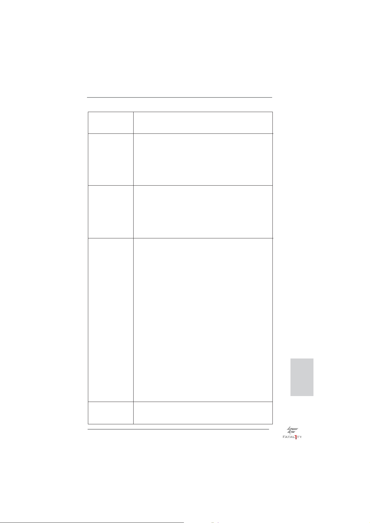
- HD Audiobuchse: Lautsprecher hinten / Mitte / Bass /
Audioeingang / Lautsprecher vorne / Mikrofon
(siehe VORSICHT 7)
®
SATA3 - 2 x SATA 3-Anschlüsse (6,0 Gb/s) durch Intel
Z77,
unterstützt RAID- (RAID 0, RAID 1, RAID 5, RAID 10, Intel
Rapid Storage und Intel Smart Response-Technologie),
NCQ-, AHCI-und Hot Plug Funktionen
- 4 x SATA 3-Anschlüsse (6,0 Gb/s) durch ASMedia
ASM1061, unterstützt NCQ-, AHCI-und Hot Plug Funktionen
(SATA3_A4-Anschluss wird mit dem eSATA3-Port geteilt)
USB3.0 - 2 x USB 3.0-Ports an der Rückseite durch Intel
®
Z77,
unterstützt USB 1.0/2.0/3.0 mit bis zu 5 Gb/s
- 4 x USB 3.0-Ports an der Rückseite durch Etron EJ188H,
unterstützt USB 1.0/2.0/3.0 mit bis zu 5 Gb/s
- 1 x USB 3.0-Header (unterstützt zwei USB 3.0-Ports) an
der Vorderseite durch Intel
®
Z77, unterstützt USB 1.0/2.0/3.0
mit bis zu 5 Gb/s
Anschlüsse - 4 x SATA2 3,0 GB/s-Anschlüsse, unterstützen RAID- (RAID
0, RAID 1, RAID 5, RAID 10, Intel Rapid Storage und Intel
Smart Response-Technologie), NCQ-, AHCI-und Hot Plug
Funktionen
- 6 x SATA3 6,0 GB/s-Anschlüsse
- 1 x ATA133 IDE-Anschlüsse (Unterstützt bis 2 IDE-Geräte)
- 1 x FDD-Anschlüsse
- 1 x Infrarot-Modul-Header
- 1 x COM-Anschluss-Header
- 1 x HDMI_SPDIF-Anschluss
- 1 x IEEE 1394-Anschluss
- 1 x Betriebs-LED-Header
- CPU/Gehäuse/Strom lüfter-Anschluss
- 24-pin ATX-Netz-Header
- 8-pin anschluss für 12V-ATX-Netzteil
- Interne Audio-Anschlüsse
- Anschluss für Audio auf der Gehäusevorderseite
- 2 x USB 2.0-Anschlüsse (Unterstützung 4 zusätzlicher
USB 2.0-Anschlüsse)
- 1 x USB 3.0-Anschlüsse (Unterstützung 2 zusätzlicher
USB 3.0-Anschlüsse)
- 1 x Dr. Debug (Debug-LED mit 7 Segmenten)
Schnellschalter - 1 x CMOS löschen-Schalter mit LED
- 1 x Netzschalter mit LED
- 1 x Rücksetzschalter (Reset) mit LED
Fatal1ty Z77 Professional Series Motherboard
Deutsch
59
Page 60
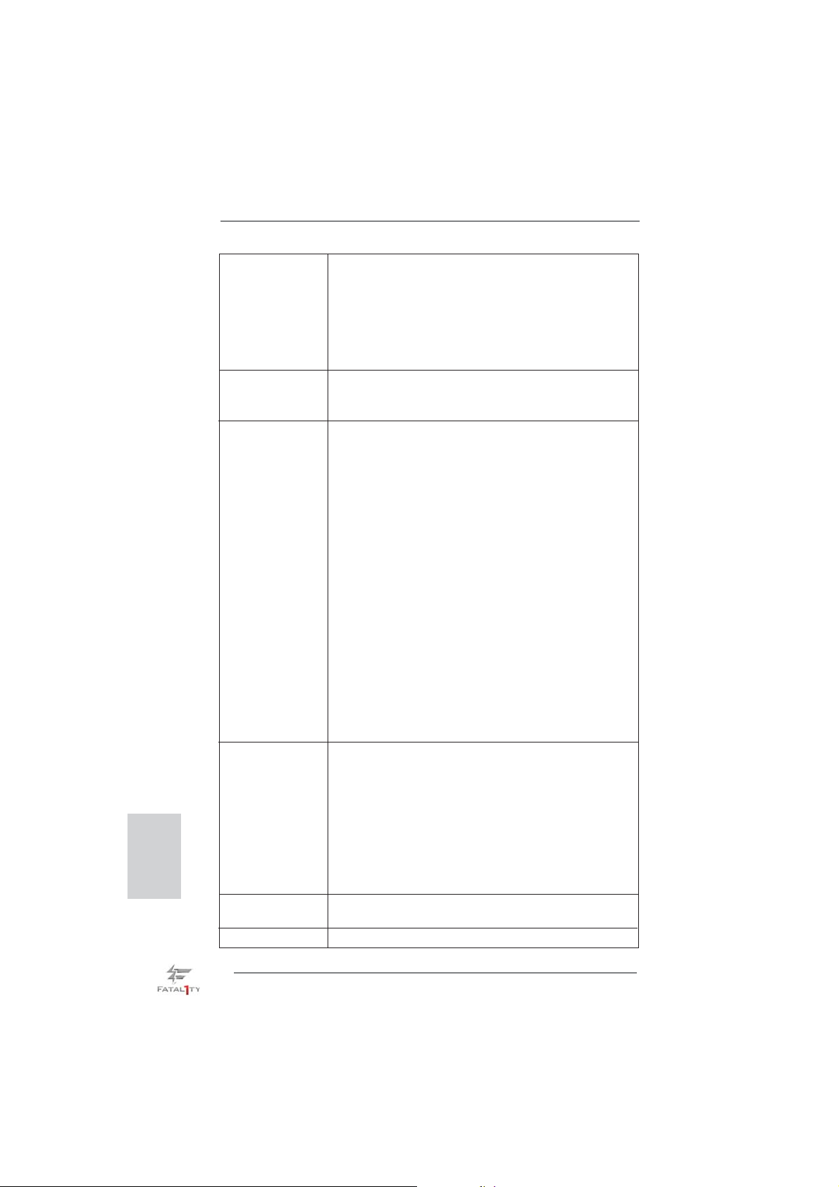
Deutsch
BIOS - 64Mb AMIs Legal BIOS UEFI mit GUI-Unterstützung
- Unterstützung für “Plug and Play”
- ACPI 1.1-Weckfunktionen
- JumperFree-Modus
- SMBIOS 2.3.1
- CPU Core, IGPU, DRAM, 1.8V PLL, VTT, VCCSA
Stromspannung Multianpassung
CD d’assistance - Treiber, Dienstprogramme, Antivirussoftware (Probeversion),
CyberLink MediaEspresso 6.5-Testversion, ASRock MAGIX Multimedia-Suite - OEM
Einzigartige - F-Stream (siehe VORSICHT 8)
Eigenschaft - ASRock Sofortstart
- ASRock Instant Flash (siehe VORSICHT 9)
- ASRock APP Charger (siehe VORSICHT 10)
- ASRock SmartView (siehe VORSICHT 11)
- ASRock XFast USB (siehe VORSICHT 12)
- ASRock XFast LAN (siehe VORSICHT 13)
- ASRock XFast RAM (siehe VORSICHT 14)
- ASRock Crashless BIOS (siehe VORSICHT 15)
- Lucid Virtu Universal MVP (siehe VORSICHT 16)
* Lucid Virtu Universal MVP kann nur durch GPU-integrierte
Prozessoren unterstützt werden.
- Hybrid Booster:
- Schrittloser CPU-Frequenz-Kontrolle
(siehe VORSICHT 17)
- ASRock U-COP (siehe VORSICHT 18)
- Boot Failure Guard (B.F.G. – Systemstartfehlerschutz)
- Combo-Kühleroption (siehe VORSICHT 19)
- Gute Nacht-LED
Hardware Monitor - Überwachung der CPU-Temperatur
- Motherboardtemperaturerkennung
- Drehzahlmessung für CPU/Gehäuse/Strom lüfter
- Geräuscharmer CPU-/Gehäuselüfter (ermöglicht die au
tomatische Anpassung der Gehäuselüftergeschwindigkeit
durch CPU-Temperatur)
- Mehrstufi ge Geschwindigkeitssteuerung für CPU/Gehäuse
lüfter
- Spannungsüberwachung: +12V, +5V, +3.3V, Vcore
®
Betriebssysteme - Unterstützt Microsoft
Vista
TM
64-Bit / XP / XP 64-Bit (siehe VORSICHT 20)
Windows® 7 / 7 64-Bit / VistaTM /
Zertifi zierungen - FCC, CE, WHQL
60
Fatal1ty Z77 Professional Series Motherboard
Page 61

- Gemäß Ökodesign-Richtlinie (ErP/EuP) (Stromversorgung
gemäß Ökodesign-Richtlinie (ErP/EuP) erforderlich)
(siehe VORSICHT 21)
* Für die ausführliche Produktinformation, besuchen Sie bitte unsere Website:
http://www.asrock.com
WARNUNG
Beachten Sie bitte, dass Overclocking, einschließlich der Einstellung im BIOS,
Anwenden der Untied Overclocking-Technologie oder Verwenden von Overclocking Werkzeugen von Dritten, mit einem gewissen Risiko behaftet ist. Overclocking kann
sich nachteilig auf die Stabilität Ihres Systems auswirken oder sogar Komponenten
und Geräte Ihres Systems beschädigen. Es geschieht dann auf eigene Gefahr und
auf Ihre Kosten. Wir übernehmen keine Verantwortung für mögliche Schäden, die
aufgrund von Overclocking verursacht wurden.
VORSICHT!
1. Die Einstellung der “Hyper-Threading Technology”, fi nden Sie auf Seite
73 des auf der Support-CD enthaltenen Benutzerhandbuches beschrieben.
2. Dieses Motherboard unterstützt Dual-Kanal-Speichertechnologie. Vor
Implementierung der Dual-Kanal-Speichertechnologie müssen Sie die Installationsanleitung für die Speichermodule auf Seite 19 zwecks richtiger
Installation gelesen haben.
3. Durch Betriebssystem-Einschränkungen kann die tatsächliche Speichergröße weniger als 4 GB betragen, da unter Windows
etwas Speicher zur Nutzung durch das System reserviert wird. Unter
Windows® OS mit 64-Bit-CPU besteht diese Einschränkung nicht. Sie
können ASRock XFast RAM zur Nutzung des Speichers, den Windows®
nicht verwenden kann, einsetzen.
4. Unterstützt nur der PCIE2 und PCIE4-Steckplatz Geschwindigkeiten der
3ten Generation. Damit Sie PCI Express mit der Geschwindigkeit der
3ten Generation nutzen können, müssen Sie einen Ivy Bridge-Prozessor
installieren. Wenn Sie einen Sandy Bridge-Prozessor installieren, läuft
PCI Express nur bei der Geschwindigkeit der 2ten Generation.
5. Die Maximalspeichergröße ist von den Chipshändler defi niert und umge-
tauscht. Bitte überprüfen Sie Intel
6. xvYCC und Deep Color werden nur unter Windows® 7 64-Bit / 7 unterstützt. Der Deep Color-Modus wird nur aktiviert, wenn der Bildschirm
12bpc in EDID unterstützt. HBR wird unter Windows
64 Bit / VistaTM unterstützt.
7. Der Mikrofoneingang dieses Motherboards unterstützt Stereo- und MonoModi. Der Audioausgang dieses Motherboards unterstützt 2-Kanal-,
4-Kanal-, 6-Kanal- und 8-Kanal-Modi. Stellen Sie die richtige Verbindung
anhand der Tabelle auf Seite 5 her.
®
website für die neuliche Information.
®
7 / Vista™ / XP
®
7 64 Bit / 7 / VistaTM
Deutsch
Fatal1ty Z77 Professional Series Motherboard
61
Page 62

Deutsch
8. F-Stream ist ein Alles-in-einem-Werkzeug zur Feineinstellung
verschiedener Systemfunktionen an einer benutzerfreundlichen
Schnittstelle; diese beinhaltet Hardware-Überwachung, Lüftersteuerung,
Übertaktung, OC DNA und IES. Über die Hardware-Überwachung
können Sie die Hauptsystemdaten einsehen. Die Lüftersteuerung zeigt
Ihnen zur Anpassung Lüftergeschwindigkeit und Temperatur an. Bei
der Übertaktung können Sie die CPU-Frequenz zur Erzielung optimaler
Systemleistung übertakten. OC DNA ermöglicht Ihnen die Speicherung
Ihrer OC-Einstellungen als Profi l, welches Sie mit Freunden teilen
können. Ihre Freunde können das OC-Profi l dann in ihrem System laden
und so die gleichen OC-Einstellungen erzielen. Per IES (Intelligent
Energy Saver) kann der Spannungsregulator bei Inaktivität der CPU-
Kerne die Anzahl an Ausgangsphasen zur Steigerung der Effi zienz
reduzieren – ohne die Rechenleistung zu beeinträchtigen.
9. ASRock Instant Flash ist ein im Flash-ROM eingebettetes BIOS-Flash-
Programm. Mithilfe dieses praktischen BIOS-Aktualisierungswerkzeugs
können Sie das System-BIOS aktualisieren, ohne dafür zuerst Betriebs-
systeme wie MS-DOS oder Windows
Programm bekommen Sie durch Drücken der <F6>-Taste während des
POST-Vorgangs oder durch Drücken der <F2>-Taste im BIOS-Setup-
Menü Zugang zu ASRock Instant Flash. Sie brauchen dieses Werkzeug
einfach nur zu starten und die neue BIOS-Datei auf Ihrem USB-Flash-
Laufwerk, Diskettenlaufwerk oder der Festplatte zu speichern, und schon
können Sie Ihr BIOS mit nur wenigen Klickvorgängen ohne Bereitstellung
einer zusätzlichen Diskette oder eines anderen komplizierten Flash-Pro-
gramms aktualisieren. Achten Sie darauf, dass das USB-Flash-Laufwerk
oder die Festplatte das Dateisystem FAT32/16/12 benutzen muss.
10. Wenn Sie nach einer schnelleren, weniger eingeschränkten Möglich-
keit zur Aufl adung Ihrer Apple-Geräte (z. B. iPhone/iPad/iPod touch)
suchen, bietet ASRock Ihnen eine wunderbare Lösung – den ASRock
APP Charger. Installieren Sie einfach den ASRock APP Charger-Treiber;
dadurch lädt sich Ihr iPhone wesentlich schneller über einen Computer-
auf – genaugenommen bis zu 40 % schneller als zuvor. Der ASRock APP
Charger ermöglicht Ihnen die schnelle Aufl adung mehrerer Apple-Geräte
gleichzeitig; der Ladevorgang wird sogar dann fortgesetzt, wenn der PC
den Ruhezustand (S1), Suspend to RAM-Modus (S3) oder Tiefschlafmo-
dus (S4) aufruft oder ausgeschaltet wird (S5). Nach der Installation des
APP Charger-Treibers können Sie im Handumdrehen das großartigste
Ladeerlebnis überhaupt genießen.
ASRock-Webseite: http://www.asrock.com/Feature/AppCharger/index.
asp
11.
SmartView, eine neue Internetbrowserfunktion, ist eine intelligente IE-
Startseite, die meist besuchte Internetseiten, Ihren Browserverlauf,
Facebook-Freunde und Nachrichten in Echtzeit miteinander kombiniert:
In einer speziellen Ansicht, die das Internet noch angenehmer und
aufregender macht. ASRock-Motherboards werden exklusiv mit der
SmartView-Software geliefert, die auch dafür sorgt, dass Sie immer mit
®
aufrufen zu müssen. Mit diesem
62
Fatal1ty Z77 Professional Series Motherboard
Page 63

Ihren Freunden in Verbindung bleiben. Die SmartView-Funktionen
können Sie mit den Windows®-Betriebssystemen 7 / 7, 64 Bit / VistaTM /
TM
Vista
64 Bit und dem Internet Explorer ab Version 8 nutzen.
ASRock-Website: http://www.asrock.com/Feature/SmartView/index.asp
12. ASRocks XFast USB dient der Steigerung der Leistungsfähigkeit Ihrer
USB-Speichergeräte. Die Leistung kann je nach Eigenschaften des
Gerätes variieren.
13. ASRock XFast LAN bietet einen schnelleren Internetzugang mit den
nachfolgenden Vorteilen. LAN-Anwendungspriorisierung: Hiermit kon-
fi gurieren Sie auf ideale Weise Ihre Anwendungspriorität und/oder fügen
neue Programme hinzu. Niedrigere Latenzzeit bei Spielen: Nach Einstel
lung einer höheren Online-Gamepriorität kann hiermit die Latenzzeit bei
Spielen herabgesetzt werden. Datenverkehrsgestaltung: Sie können
Youtube-Videos in HD anzeigen und gleichzeitig Dateien herunterladen.
Echtzeitanalyse Ihrer Daten: Über das Statusfenster können Sie schnell
ermitteln, welche Datenströme zur Zeit übertragen werden.
14. ASRock XFast RAM ist eine neue Funktion, die beim F-Stream integriert
ist. Sie ermöglicht die vollständige Nutzung des Speicherplatzes, der
unter Windows®-Betriebssystemen mit 32-Bit-CPU nicht verwendet
werden kann. ASRock XFast RAM verkürzt die Ladezeit zuvor besuchter
Webseiten, was das Surfen im Internet mehr denn je beschleunigt. Auch
die Arbeit mit Adobe Photoshop erfolgt fünfmal schneller. Ein weiterer
Vorteil von ASRock XFast RAM liegt in der Reduzierung der Häufi gkeit
des Zugriffs auf SSDs bzw. HDDs zur Verlän gerung deren Lebenszeit.
15. ASRock Crashless BIOS ermöglicht Benutzern die Aktualisierung ihres
BIOS, ohne dass diese Fehler fürchten müssen. Falls während der BIOSAktualisierung ein Stromausfall auftritt, setzt ASRock Crashless BIOS
die BIOS-Aktualisierung automatisch fort, sobald die Stromversorgung
wiederhergestellt ist. Bitte beachten Sie, dass alle BIOS-Dateien zuerst
im Stammverzeichnis Ihres USB-Datenträgers platziert werden müssen.
Diese Funktion wird nur von USB 2.0-Ports unterstützt.
16. Virtu Universal MVP beinhaltet die Basisfunktionen der Virtu UniversalTechnologie, die integrierte GPU und separate GPU zur Erzielung optimaler Funktionalität virtualisiert. Verfügt zudem über Virtual VsyncTM für
kompromisslose visuelle Qualität. Dank der zusätzlichen Vorzüge der
HyperFormance-Technologie verbessert Virtu Universal MVP die Spielleistung durch intelligente Reduzierung redundanter Rendering-Aufgaben
im Fluss zwischen CPU, GPU und Anzeigegerät.
17. Obwohl dieses Motherboard stufenlose Steuerung bietet, wird Overclocking nicht empfohlen. Frequenzen, die über den für den jeweiligen
Prozessor vorgesehenen liegen, können das System instabil werden
lassen oder die CPU beschädigen.
18. Wird eine Überhitzung der CPU registriert, führt das System einen automatischen Shutdown durch. Bevor Sie das System neu starten, prüfen
Sie bitte, ob der CPU-Lüfter am Motherboard richtig funktioniert, und
stecken Sie bitte den Stromkabelstecker aus und dann wieder ein. Um
die Wärmeableitung zu verbessern, bitte nicht vergessen, etwas Wärmel-
eitpaste zwischen CPU und Kühlkörper zu sprühen.
Fatal1ty Z77 Professional Series Motherboard
Deutsch
63
Page 64

19. Die Combo-Kühleroption bietet die fl exible Möglichkeit zur Aufnahme von
drei verschiedenen CPU-Kühlertypen, Socket LGA 775, LGA 1155 und LGA
1156. Beachten Sie bitte, dass nicht alle 775 und 1156 CPU-Lüfter verwendet werden können.
20. ASRock XFast RAM wird von Microsoft® Windows® XP / XP 64 Bit nicht
unterstützt. Intel
wird von Microsoft® Windows® VistaTM / VistaTM 64 Bit / XP / XP 64 Bit
nicht unterstützt.
21. EuP steht für Energy Using Product und kennzeichnet die Ökodesign-Richt-
linie, die von der Europäischen Gemeinschaft zur Festlegung des Energieverbrauchs von vollständigen Systemen in Kraft gesetzt wurde. Gemäß
dieser Ökodesign-Richtlinie (EuP) muss der gesamte Netzstromverbrauch
von vollständigen Systemen unter 1,00 Watt liegen, wenn sie ausgeschaltet sind. Um dem EuP-Standard zu entsprechen, sind ein EuP-fähiges
Motherboard und eine EuP-fähige Stromversorgung erforderlich. Gemäß
einer Empfehlung von Intel muss eine EuP-fähige Stromversorgung dem
Standard entsprechen, was bedeutet, dass bei einem Stromverbrauch von
100 mA die 5-Volt-Standby-Energieeffi zienz höher als 50% sein sollte. Für
die Wahl einer EuP-fähigen Stromversorgung empfehlen wir Ihnen, weitere
Details beim Hersteller der Stromversorgung abzufragen.
®
Smart Connect-Technologie und Intel® USB 3.0-Ports
Deutsch
64
Fatal1ty Z77 Professional Series Motherboard
Page 65
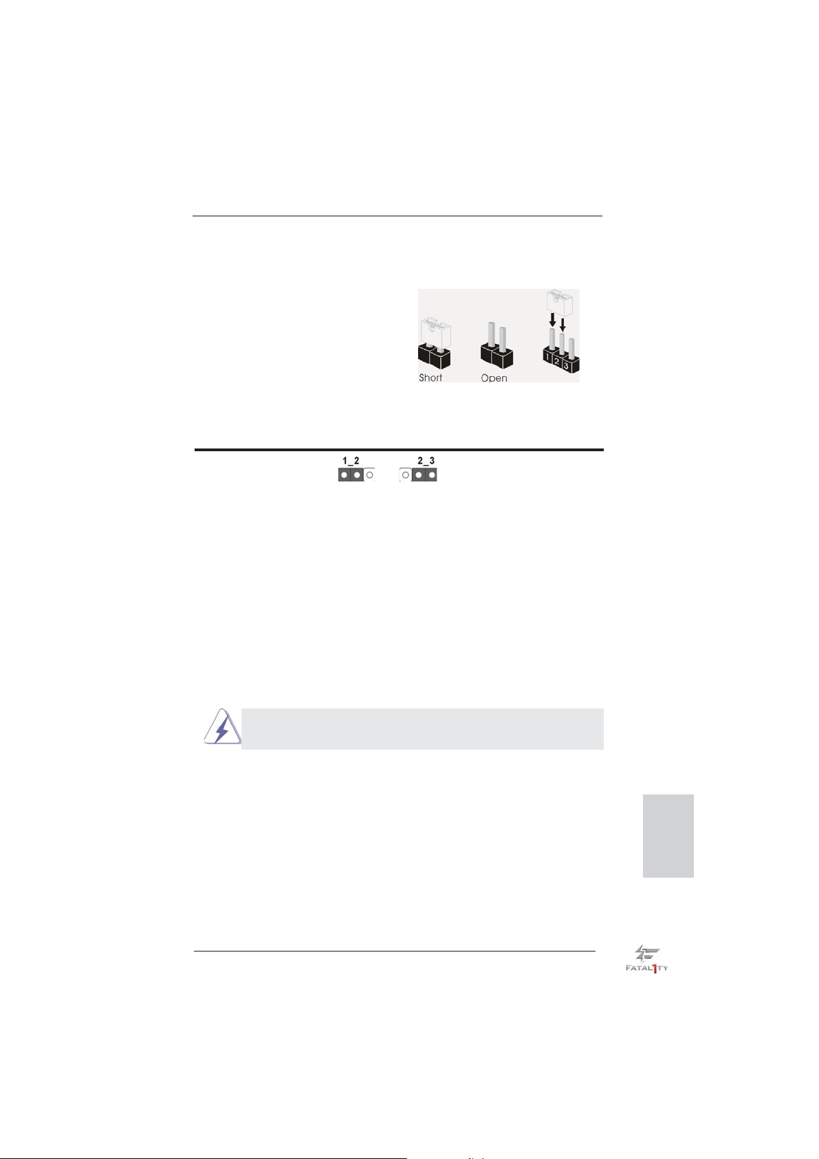
1.3 Einstellung der Jumper
Die Abbildung verdeutlicht, wie Jumper
gesetzt werden. Werden Pins durch
Jumperkappen verdeckt, ist der Jumper
“Gebrückt”. Werden keine Pins durch
Jumperkappen verdeckt, ist der Jumper
“Offen”. Die Abbildung zeigt einen 3-Pin
Jumper dessen Pin1 und Pin2 “Gebrückt” sind, bzw. es befi ndet sich eine
Jumper-Kappe auf diesen beiden Pins.
Jumper Einstellun Beschreibung
CMOS löschen
(CLRCMOS1, 3-Pin jumper)
(siehe S.4, No. 27)
Hinweis:
CLRCMOS1 ermöglicht Ihnen die Löschung der Daten im CMOS. Zum
Löschen und Zurücksetzen der Systemparameter auf die Standardeinrichtung
schalten Sie den Computer bitte aus und trennen das Netzkabel von der
Stromversorgung. Warten Sie 15 Sekunden, schließen Sie dann Pin2 und
Pin3 am CLRCMOS1 über einen Jumper fünf Sekunden lang kurz. Sie
sollten das CMOS allerdings nicht direkt nach der BIOS-Aktualisierung
löschen. Wenn Sie das CMOS nach Abschluss der BIOS-Aktualisierung
löschen müssen, fahren Sie zuerst das System hoch. Fahren Sie es dann
vor der CMOS-Löschung herunter. Bitte beachten Sie, dass Kennwort,
Datum, Uhrzeit, benutzerdefi niertes Profi l, 1394 GUID und MAC-Adresse
nur gelöscht werden, wenn die CMOS-Batterie entfernt wird.
DefaultEinstellung
CMOS
löschen
Der CMOS löschen-Schalter hat dieselbe Funktion wie der CMOS
löschen-Jumper.
Fatal1ty Z77 Professional Series Motherboard
Deutsch
65
Page 66
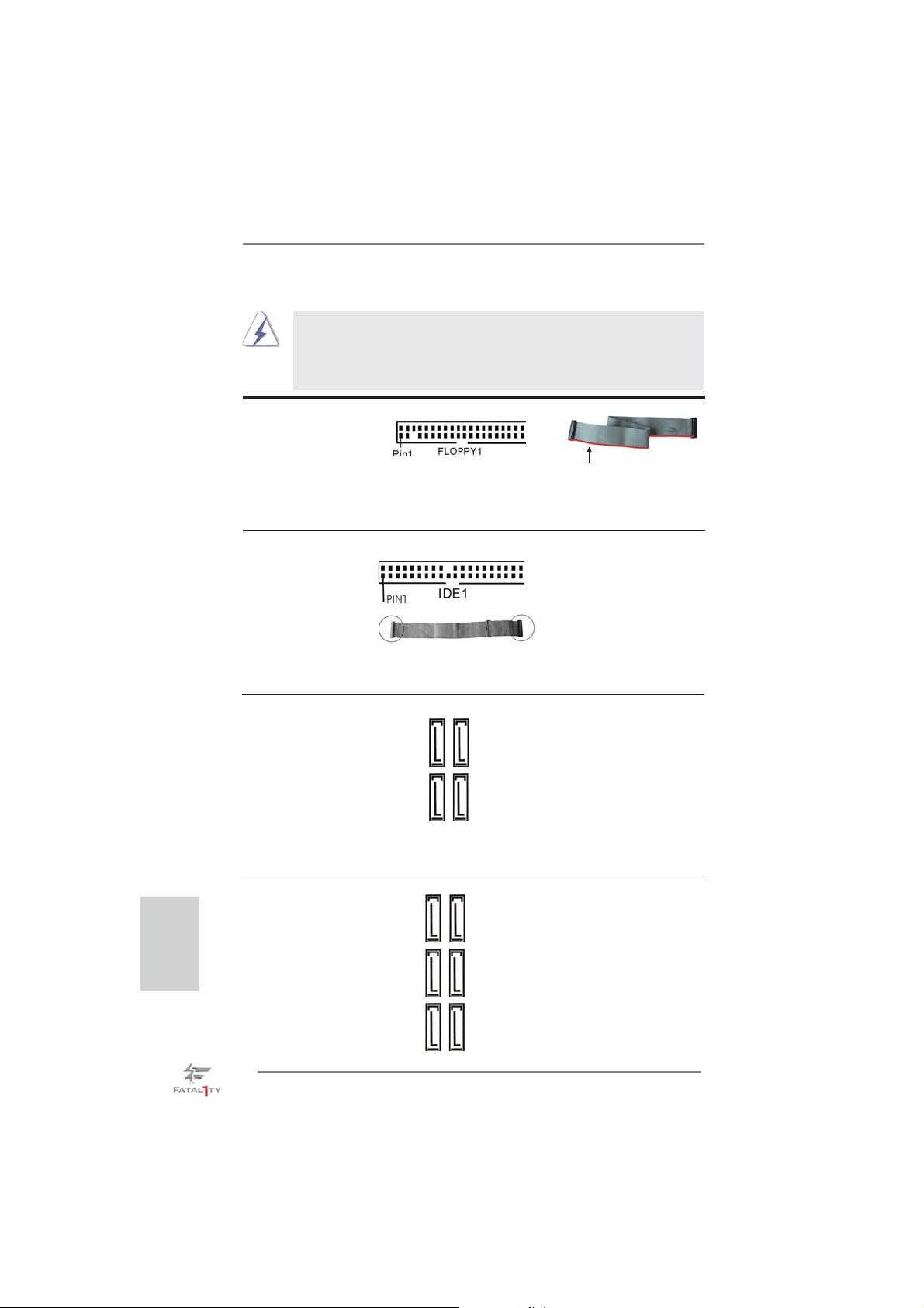
1.4 Integrierte Header und Anschlüsse
Anschluss für das
Floppy-Laufwerk
(33-Pin FLOPPY1)
(siehe S.4 - No. 30)
Hinweis: Achten Sie darauf, dass die rotgestreifte Seite des Kabel mit der Stift 1-
Seite des Anschlusses verbunden wird.
Primärer IDE-Anschluss (schwarz)
(39-pin IDE1, siehe S.4 - No. 8)
Blauer Anschluss Schwarzer Anschluss
zum Motherboard zur Festplatte
80-adriges ATA 66/100/133 Kabel
Hinweis: Details entnehmen Sie bitte den Anweisungen Ihres IDE-Gerätehändlers.
Seriell-ATA2-Anschlüsse Diese vier Serial ATA2-
(SATA2_2_3: siehe S.4 - No. 14)
(SATA2_4_5: siehe S.4 - No. 15)
für interne
Massenspeichergeräte. Die
aktuelle SATA2- Schnittstelle
ermöglicht eine
Datenübertragungsrate bis
3,0 Gb/s.
Integrierte Header und Anschlüsse sind KEINE Jumper. Setzen Sie KEINE Jumperkappen auf diese Header und Anschlüsse. Wenn Sie Jumperkappen auf Header und Anschlüsse setzen, wird das Motherboard
unreparierbar beschädigt!
(SATA2-)Verbínder
SATA2_2 SATA2_3
unterstützten SATA-Datenkabel
SATA2_4 SATA2_5
die rotgestreifte Seite auf Stift 1
Deutsch
Seriell-ATA3-Anschlüsse Diese sechs Serial ATA3-
(SATA3_0_1:
siehe S.4 - No. 13)
(SATA3_A1_A2:
siehe S.4 - No. 12)
(SATA3_A3_A4:
siehe S.4 - No. 11)
Datenübertragungsrate bis 6,0
(SATA3-)Verbínder
unterstützten SATA-Datenkabel
SATA3_A3 SATA3_A4
für interne
Massenspeichergeräte. Die
SATA3_A1 SATA3_A2
aktuelle SATA3- Schnittstelle
ermöglicht eine
SATA3_0 SATA3_1
Gb/s. Wenn Sie die
66
Fatal1ty Z77 Professional Series Motherboard
Page 67
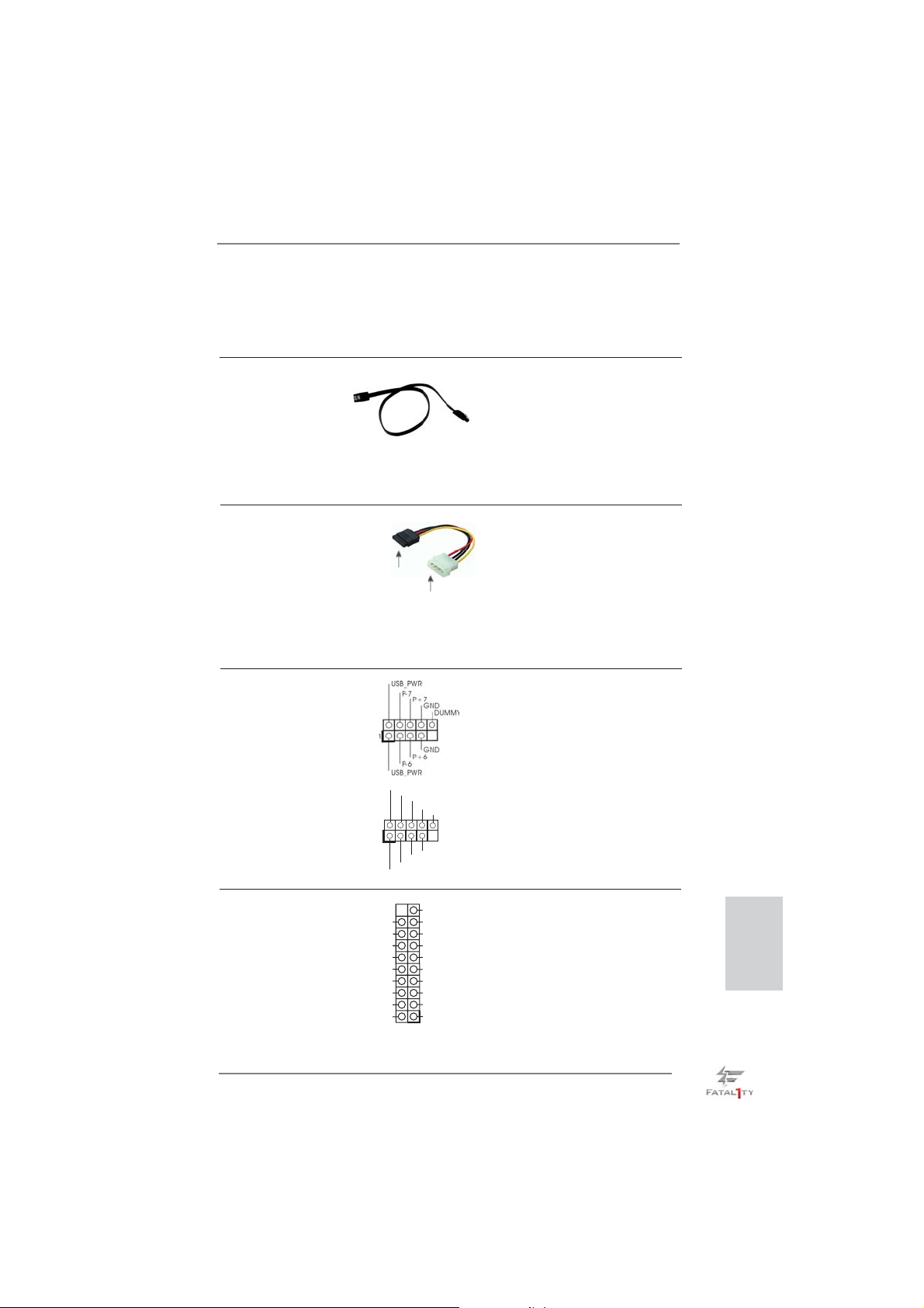
Festplatte am eSATA3-Port an
der Rückblende anschließen,
wird der interne SATA3_A4 Anschluss deaktiviert.
Serial ATA- (SATA-) SJedes Ende des SATA
Datenkabel Datenkabels kann an die SATA
(Option)
/ SATA2 / SATA3 Festplatte
oder das SATA2 / SATA3
Verbindungsstück auf dieser
Hauptplatine angeschlossen
werden.
Serial ATA- (SATA-) Verbinden Sie das schwarze
Stromversorgungskabel Ende des SATA-Netzkabels mit
(Option)
dem Netzanschluss am
Laufwerk. Verbinden Sie dann
das weiße Ende des SATA-
SATA-HDD-Stromanschluss
Stromversorgungskabels mit
Verbindung zum
Verbindung zum
Netzteil
dem Stromanschluss des
Netzteils.
USB 2.0-Header Zusätzlich zu den sechs
(9-pol. USB_6_7)
(siehe S.4 - No. 24)
üblichen USB 2.0-Ports an den
I/O-Anschlüssen befi nden sich
zwei USB 2.0- Anschlussleisten
am Motherboard. Pro USB 2.0-
(9-pol. USB_8_9)
(siehe S.4 - No. 25)
Anschlussleiste werden zwei
USB 2.0-Ports unterstützt.
1
USB_PWR
P-9
P-8
USB_PWR
P+9
P+8
GND
GND
DUMMY
USB 3.0-Header Neben sechs Standard-USB
(19-pol. USB3_6_7)
(siehe S.4 - No. 9)
3.0-Ports am E/A-Panel
befi ndet sich ein USB 3.0-
Header an diesem
Motherboard. Dieser USB 3.0 Header kann zwei USB 3.0 Ports unterstützen.
Vbus
IntA_P6_SSRX-
IntA_P6_SSRX+
GND
IntA_P6_SSTX-
IntA_P6_SSTX+
GND
IntA_P6_D-
IntA_P6_D+
VbusVbus
IntA_P7_SSRX-
IntA_P7_SSRX+
GND
IntA_P7_SSTX-
IntA_P7_SSTX+
GND
IntA_P7_D-
IntA_P7_D+
DUMMY
Fatal1ty Z77 Professional Series Motherboard
Deutsch
67
Page 68
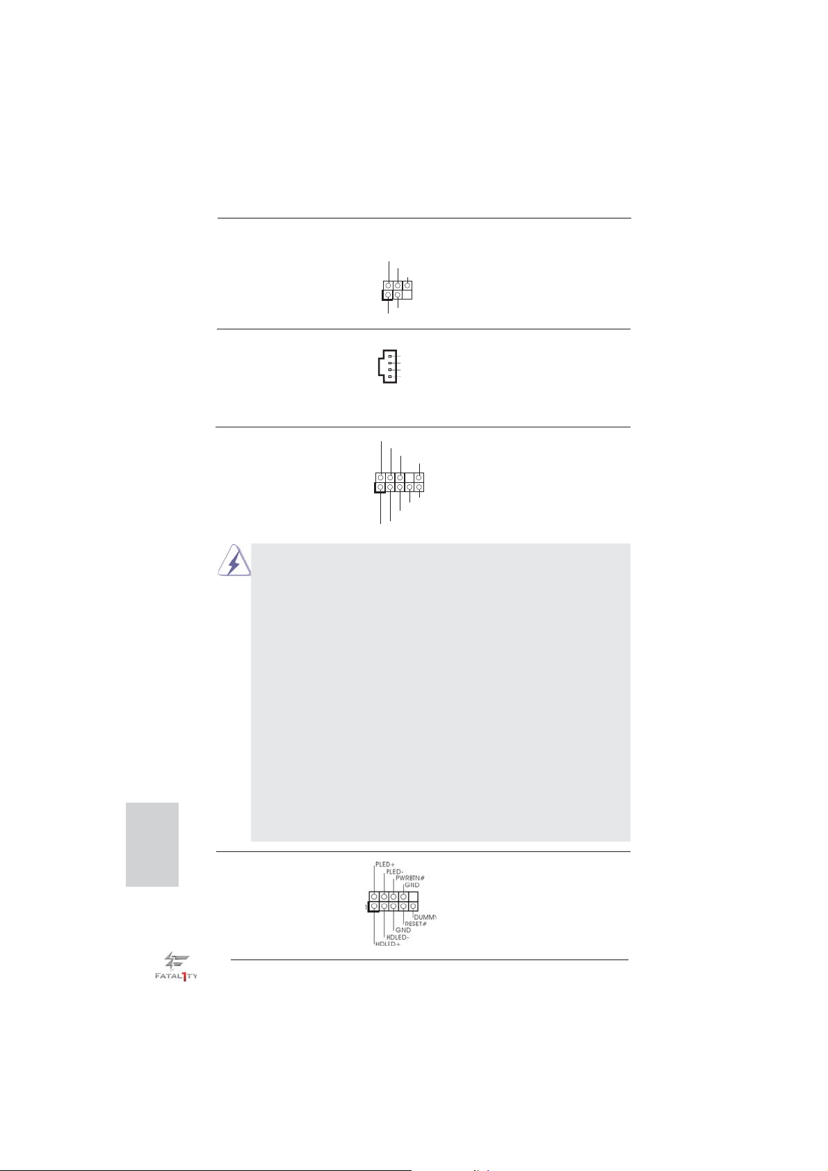
Infrarot-Modul-Header Dieser Header unterstützt ein
(5-pin IR1)
optionales, drahtloses Sende-
(siehe S.4 - No. 29)
und Empfangs-Infrarotmodul.
IRTX
+5VSB
DUMMY
1
GND
IRRX
Interne Audio-Anschlüsse Diese ermöglichen Ihnen
CD1
CD-L
GND
GND
CD- R
(4-Pin CD1)
(siehe S.4 - No. 42)
Stereo-Signalquellen, wie z. B.
CD-ROM, DVD-ROM, TV-Tuner
oder MPEG-Karten mit Ihrem
System zu verbinden.
Deutsch
Anschluss für Audio auf Dieses Interface zu einem
der Gehäusevorderseite Audio-Panel auf der Vorder
(9-Pin HD_AUDIO1)
(siehe S.4 - No. 32)
seite Ihres Gehäuses,
ermöglicht Ihnen eine bequeme
Anschlussmöglichkeit und
Kontrolle über Audio-Geräte.
1
GND
PRESENCE#
MIC2_R
MIC2_L
MIC_RET
J_SENSE
OUT2_R
OUT_RET
OUT2_L
1. High Defi nition Audio unterstützt Jack Sensing (automatische Erkennung falsch
angeschlossener Geräte), wobei jedoch die Bildschirmverdrahtung am Gehäuse
HDA unterstützen muss, um richtig zu funktionieren. Beachten Sie bei der
Installation im System die Anweisungen in unserem Handbuch und im
Gehäusehandbuch.
2. Wenn Sie die AC’97-Audioleiste verwenden, installieren Sie diese wie
nachstehend beschrieben an der Front-Audioanschlussleiste:
A. Schließen Sie Mic_IN (MIC) an MIC2_L an.
B. Schließen Sie Audio_R (RIN) an OUT2_R und Audio_L (LIN) an OUT2_L an.
C. Schließen Sie Ground (GND) an Ground (GND) an.
D. MIC_RET und OUT_RET sind nur für den HD-Audioanschluss gedacht. Diese
Anschlüsse müssen nicht an die AC’97-Audioleiste angeschlossen werden.
E. So aktivieren Sie das Mikrofon an der Vorderseite.
Bei den Betriebssystemen Windows
®
XP / XP 64 Bit:
Wählen Sie „Mixer“. Wählen Sie „Recorder“ (Rekorder). Klicken Sie dann auf
„FrontMic“ (Vorderes Mikrofon).
Bei den Betriebssystemen Windows
®
7 / 7 64 Bit / VistaTM / VistaTM 64 Bit:
Wählen Sie im Realtek-Bedienfeld die „FrontMic“ (Vorderes Mikrofon) Registerkarte. Passen Sie die „Recording Volume“ (Aufnahmelautstärke) an.
System Panel-Header Dieser Header unterstützt
(9-pin PANEL1)
(siehe S.4 - No. 21)
mehrere Funktion der
Systemvorderseite.
68
Fatal1ty Z77 Professional Series Motherboard
Page 69
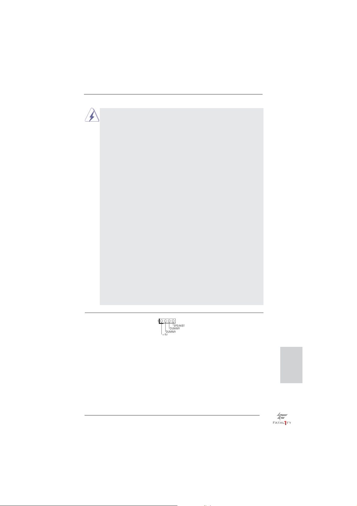
Schließen Sie die Ein-/Austaste, die Reset-Taste und die
Systemstatusanzeige am Gehäuse an diesen Header an; befolgen Sie
dabei die nachstehenden Hinweise zur Pinbelegung. Beachten Sie die
positiven und negativen Pins, bevor Sie die Kabel anschließen.
PWRBTN (Ein-/Ausschalter):
Zum Anschließen des Ein-/Ausschalters an der Frontblende des Gehäu
ses. Sie können konfi gurieren, wie das System mit Hilfe des
Ein-/Ausschalters ausgeschaltet werden können soll.
RESET (Reset-Taste):
Zum Anschließen der Reset-Taste an der Frontblende des Gehäuses.
Mit der Reset-Taste können Sie den Computer im Falle eines Absturzes
neu starten.
PLED (Systembetriebs-LED):
Zum Anschließen der Betriebsstatusanzeige an der Frontblende des
Gehäuses. Die LED leuchtet, wenn das System in Betrieb ist. Die LED
blinkt, wenn sich das System im Ruhezustand S1/S3 befi ndet. Die LED
schaltet sich aus, wenn sich das System in den Modi S4 befi ndet
oder ausgeschaltet ist (S5).
HDLED (Festplattenaktivitäts-LED):
Zum Anschließen der Festplattenaktivitäts-LED an der Frontblende des
Gehäuses. Die LED leuchtet, wenn die Festplatte Daten liest oder
schreibt.
Das Design der Frontblende kann je nach Gehäuse variiere. Ein
Frontblendenmodul besteht hauptsächlich aus einer Ein-/Austaste, einer
Reset-Taste, einer Betriebs-LED, einer Festplattenaktivitäts-LED,
Lautsprechern, etc. Stellen Sie beim Anschließen des
Frontblendenmoduls Ihres Gehäuses an diesem Header sicher, dass die
Kabel- und Pinbelegung korrekt übereinstimmen.
Gehäuselautsprecher-Header Schließen Sie den
(4-pin SPEAKER1)
(siehe S.4 - No. 20)
Gehäuselautsprecher an
diesen Header an.
Fatal1ty Z77 Professional Series Motherboard
Deutsch
69
Page 70
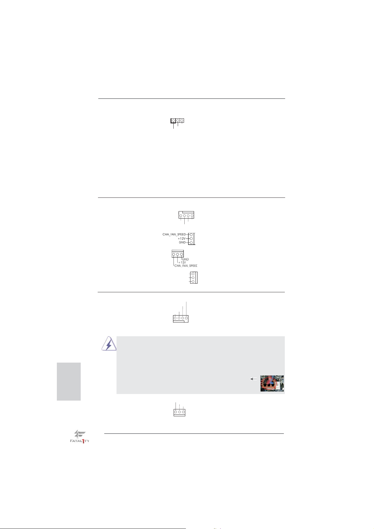
Betriebs-LED-Header Bitte schließen Sie die
(3-pin PLED1)
(siehe S.4 - No. 19)
Betriebs-LED des Gehäuses
zur Anzeige des
1
PLED+
PLED+
PLED-
Systembetriebsstatus an
diesem Header an. Die LED
leuchtet, wenn das System in
Betrieb ist. Die LED blinkt im
S1/S3-Zustand. Im S4- oder
S5-Zustand (ausgeschaltet)
leuchtet die LED nicht.
Gehäuse und Strom lüfteranschlüsse Verbinden Sie die Lüfterkabel
(4-pin CHA_FAN1)
(siehe S.4, No. 26)
den Schutzleiterstift
(3-pin CHA_FAN2)
(siehe S.4 - No. 43)
CHA_FAN3-
(3-pin CHA_FAN3)
(siehe S.4 - No. 22)
(3-pin PWR_FAN1)
(siehe S.4 - No. 41)
mit den Lüfteranschlüssen,
wobei der schwarze Draht an
FAN_SPEED_CONTROL
CHA_FAN_SPEED
+12V
GND
angeschlossenwird.
CHA_FAN1-, CHA_FAN2- und
unterstützen
Lüftersteuerung.
PWR_FAN_SPEED
+12V
GND
Deutsch
CPU-Lüfteranschluss Verbinden Sie das CPU -
(4-pin CPU_FAN1)
(siehe S.4 - No. 3)
Lüfterkabel mit diesem
Anschluss und passen Sie den
schwarzen Draht dem
Erdungsstift an.
FAN_SPEED_CONTROL
CPU_FAN_SPEED
+12V
GND
1 2 3 4
Obwohl dieses Motherboard einen vierpoligen CPU-Lüfteranschluss
(Quiet Fan) bietet, können auch CPU-Lüfter mit dreipoligem Anschluss
angeschlossen werden; auch ohne Geschwindigkeitsregulierung. Wenn
Sie einen dreipoligen CPU-Lüfter an den CPU-Lüferanschluss dieses
Motherboards anschließen möchten, verbinden Sie ihn bitte mit den
Pins 1 – 3.
Pins 1–3 anschließen
Lüfter mit dreipoligem Anschluss installieren
(3-pin CPU_FAN2)
(sieche S.4 - No. 4)
GND
+12V
CPU_FAN_SPEED
70
Fatal1ty Z77 Professional Series Motherboard
Page 71
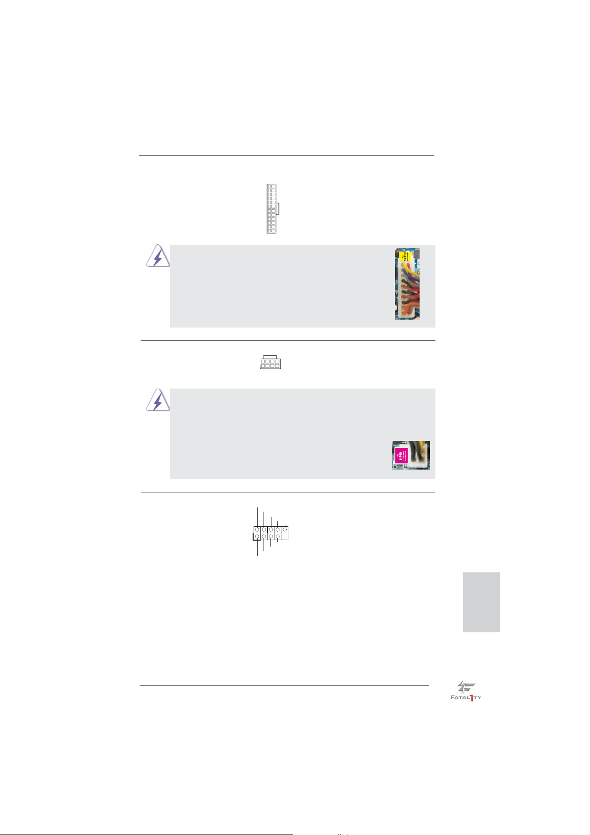
ATX-Netz-Header Verbinden Sie die ATX-
(24-pin ATXPWR1)
(siehe S.4 - No. 7)
Stromversorgung mit diesem
Header.
12 124
13
Obwohl dieses Motherboard einen 24-pol. ATX Stromanschluss bietet, kann es auch mit einem
12
24
24
modifi zierten traditionellen 20-pol. ATX-Netzteil
verwendet werden. Um ein 20-pol. ATX-Netzteil zu
verwenden, stecken Sie den Stecker mit Pin 1 und
Pin 13 ein.
ATX 12V Anschluss Bitte schließen Sie an diesen
(8-pin ATX12V1)
(siehe S.4 - No. 2)
Anschluss die ATX 12V
Stromversorgung an.
Installation eines 20-pol. ATX-Netzteils
8 5
4 1
1
13
13
Obwohl diese Hauptplatine 8-Pin ATX 12V Stromanschluss zur Verfügung
stellt, kann sie noch arbeiten, wenn Sie einen traditionellen 4-Pin ATX 12V
Energieversorgung adoptieren. Um die 4-Pin ATX Energieversorgung zu
verwenden, stecken Sie bitte Ihre Energieversorgung zusammen mit dem
Pin 1 und Pin 5 ein.
Installation der 4-Pin ATX 12V Energieversorgung
IEEE-1394 Header Außer einem vorgegebenem
(9-pin FRONT_1394)
(siehe S.4 - No. 28)
IEEE-1394 Port auf dem Ein-/
Ausgabe Paneel, gibt es einen
IEEE-1394 Header
(FRONT_1394) auf dieser
Hauptplatine. Dieser IEEE-1394
RXTPAM_0
1
RXTPAP_0
GND
RXTPBM_0
RXTPBP_0
GND
+12V
+12V
GND
8 5
4 1
Header kann einen IEEE-1394
Port unterstützen.
Fatal1ty Z77 Professional Series Motherboard
Deutsch
71
Page 72
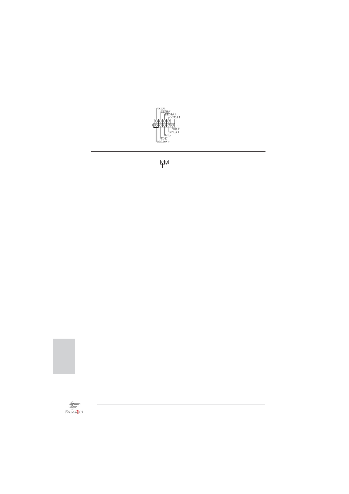
COM-Anschluss-Header Dieser COM-Anschluss- Header
(9-pin COM1)
(siehe S.4 - No. 31)
wird verwendet, um ein
COM-Anschlussmodul zu
unterstützen.
HDMI_SPDIF-Anschluss Der HDMI_SPDIF-Anschluss
(2-pin HDMI_SPDIF1)
(siehe S.4 - No. 33)
stellt einen SPDIF-
Audioausgang für eine HDMI-
1
SPDIFOUT
GND
VGA-Karte zur Verfügung und
ermöglicht den Anschluss von
HDMI-Digitalgeräten wie
Fernsehgeräten, Projektoren,
LCD-Geräten an das System.
Bitte verbinden Sie den
HDMI_SPDIF-Anschluss der
HDMI-VGA-Karte mit diesem
Anschluss.
Deutsch
72
Fatal1ty Z77 Professional Series Motherboard
Page 73
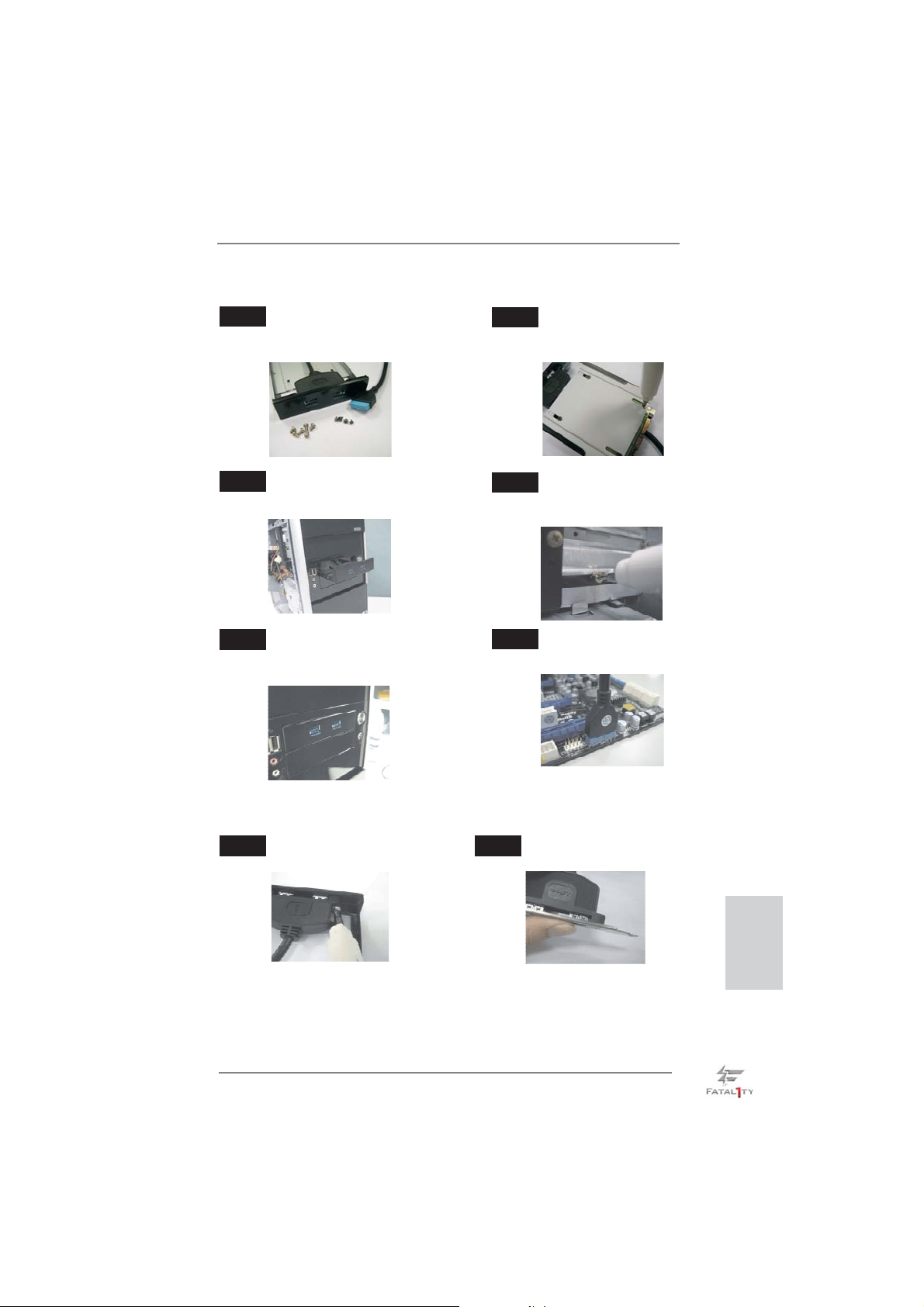
Installationsanleitung der USB 3.0-Frontblende
Schritt 1
Halten Sie die mitgelieferte USB 3.0Frontblende, vier Festplattenschrauben
und sechs Gehäuseschrauben bereit.
Schritt 2
Montieren Sie die 2,5 Zoll-HDD/SSD
mit vier Festplattenschrauben an der
USB 3.0-Frontblende.
Schritt 3
Installieren Sie die USB 3.0-Frontblende im
2,5 Zoll-Festplatteneinschub des Gehäuses.
Schritt 5
Schließen Sie das Kabel der
USB 3.0-Frontblende am USB 3.0-Header
(USB3_6_7) am Motherboard an.
Montieren Sie die USB 3.0-Frontblende
Schritt 4
mit sechs Gehäuseschrauben am
Festplatteneinschub.
Schritt 6
Die USB 3.0-Frontblende ist nun
einsatzbereit.
Installationsanleitung zum USB 3.0-Blech an der Rückwand
Schritt 1 Schritt 2
Lösen Sie die beiden Schrauben am
USB 3.0-Panel.
Schließen Sie das USB 3.0-Kabel an
das USB 3.0-Blech an.
Fatal1ty Z77 Professional Series Motherboard
Deutsch
73
Page 74
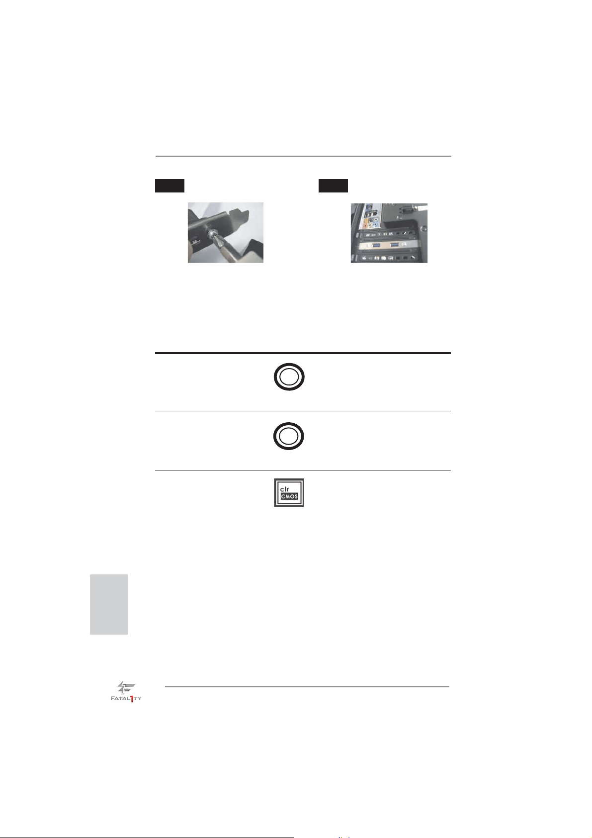
Schritt 3 Schritt 4
Fixieren Sie das USB 3.0-Blech mit
Schrauben an der Rückwand.
Setzen Sie das USB 3.0-Blech an
der Rückwand des Gehäuses ein.
1.5 Schnellschalter
Dieses Motherboard besitzt drei Schnellschalter: Netzschalter, Rücksetzschalter
(Reset) und CMOS löschen-Schalter, mit denen Benutzer das System schnell ein-/
ausschalten oder zurücksetzen oder die CMOS-Werte löschen können.
Netzschalter Der Netzschalter ist ein
(PWRBTN)
(siehe S.4 - No. 16)
ein-/ausschalten können.
Rücksetzschalter (Reset) Der Rücksetzschalter (Reset)
(RSTBTN)
(siehe S.4 - No. 17)
zurücksetzen können.
Schnellschalter, mit dem
Benutzer das System schnell
ist ein Schnellschalter, mit dem
Benutzer das System schnell
Power
Reset
Deutsch
CMOS löschen-Schalter Der CMOS löschen-Schalter ist
(CLRCBTN)
(siehe S.5 - No. 18)
ein Schnellschalter, mit dem
Benutzer die CMOS-Werte
schnell löschen können.
74
Fatal1ty Z77 Professional Series Motherboard
Page 75

2. BIOS-Information
Das Flash Memory dieses Motherboards speichert das Setup-Utility. Drücken Sie
<F2> oder <Del> während des POST (Power-On-Self-Test) um ins Setup zu gelangen, ansonsten werden die Testroutinen weiter abgearbeitet. Wenn Sie ins Setup
gelangen wollen, nachdem der POST durchgeführt wurde, müssen Sie das System
über die Tastenkombination <Ctrl> + <Alt> + <Delete> oder den Reset-Knopf auf
der Gehäusevorderseite, neu starten. Natürlich können Sie einen Neustart auch
durchführen, indem Sie das System kurz ab- und danach wieder anschalten.
Das Setup-Programm ist für eine bequeme Bedienung entwickelt worden. Es ist
ein menügesteuertes Programm, in dem Sie durch unterschiedliche Untermenüs
scrollen und die vorab festgelegten Optionen auswählen können. Für detaillierte
Informationen zum BIOS-Setup, siehe bitte das Benutzerhandbuch (PDF Datei) auf
der Support CD.
3. Software Support CD information
Dieses Motherboard unterstützt eine Reiche von Microsoft® Windows® Betriebssystemen: 7 / 7 64-Bit / Vista
beigefügte Support-CD enthält hilfreiche Software, Treiber und Hilfsprogramme, mit
denen Sie die Funktionen Ihres Motherboards verbessern können Legen Sie die
Support-CD zunächst in Ihr CD-ROM-Laufwerk ein. Der Willkommensbildschirm
mit den Installationsmenüs der CD wird automatisch aufgerufen, wenn Sie die
“Autorun”-Funktion Ihres Systems aktiviert haben.
Erscheint der Wilkommensbildschirm nicht, so “doppelklicken” Sie bitte auf das File
ASSETUP.EXE im BIN-Verzeichnis der Support-CD, um die Menüs aufzurufen.
Das Setup-Programm soll es Ihnen so leicht wie möglich machen. Es ist menügesteuert, d.h. Sie können in den verschiedenen Untermenüs Ihre Auswahl treffen und
die Programme werden dann automatisch installiert.
TM
/ Vista
TM
64-Bit / XP / XP 64-Bit. Die Ihrem Motherboard
Fatal1ty Z77 Professional Series Motherboard
Deutsch
75
Page 76

Français
1. Introduction
Merci pour votre achat d’une carte mère ASRock Fatal1ty Z77 Professional
Series, une carte mère très fi able produite selon les critères de qualité rigoureux de
ASRock. Elle offre des performances excellentes et une conception robuste conformément à l’engagement d’ASRock sur la qualité et la fi abilité au long terme.
Ce Guide d’installation rapide présente la carte mère et constitue un guide
d’installation pas à pas. Des informations plus détaillées concernant la carte
mère pourront être trouvées dans le manuel l’utilisateur qui se trouve sur le CD
d’assistance.
Les spécifi cations de la carte mère et le BIOS ayant pu être mis à jour, le
contenu de ce manuel est sujet à des changements sans notifi cation. Au
cas où n’importe qu’elle modifi cation intervenait sur ce manuel, la version
mise à jour serait disponible sur le site web ASRock sans nouvel avis.
Vous trouverez les listes de prise en charge des cartes VGA et CPU
également sur le site Web ASRock.
Site web ASRock, http://www.asrock.com
Si vous avez besoin de support technique en relation avec cette carte
mère, veuillez consulter notre site Web pour de plus amples informations
particulières au modèle que vous utilisez.
www.asrock.com/support/index.asp
1.1 Contenu du paquet
Carte mère ASRock Fatal1ty Z77 Professional Series
(Facteur de forme ATX: 12.0 pouces x 9.6 pouces, 30.5 cm x 24.4 cm)
Guide d’installation rapide ASRock Fatal1ty Z77 Professional Series
CD de soutien ASRock Fatal1ty Z77 Professional Series
Six câbles de données de série ATA (SATA) (en option)
Deux câble d’alimentation de série ATA (SATA) HDD (en option)
Un I/O Panel Shield
Un panneau avant USB 3.0
Quatre HDD vis
Six châssis vis
Un support arrière USB 3.0
Un carte 2S_Pont_ASRock SLI
76
ASRock vous rappelle...
Pour bénéfi cier des meilleures performances sous Windows® 7 / 7 64 bits
TM
/ Vista
/ VistaTM 64 bits, il est recommandé de paramétrer l'option BIOS
dans Confi guration de stockage en mode AHCI. Pour plus de détails sur
l'installation BIOS, référez-vous au "Mode d'emploi" sur votre CD de support.
Fatal1ty Z77 Professional Series Motherboard
Page 77
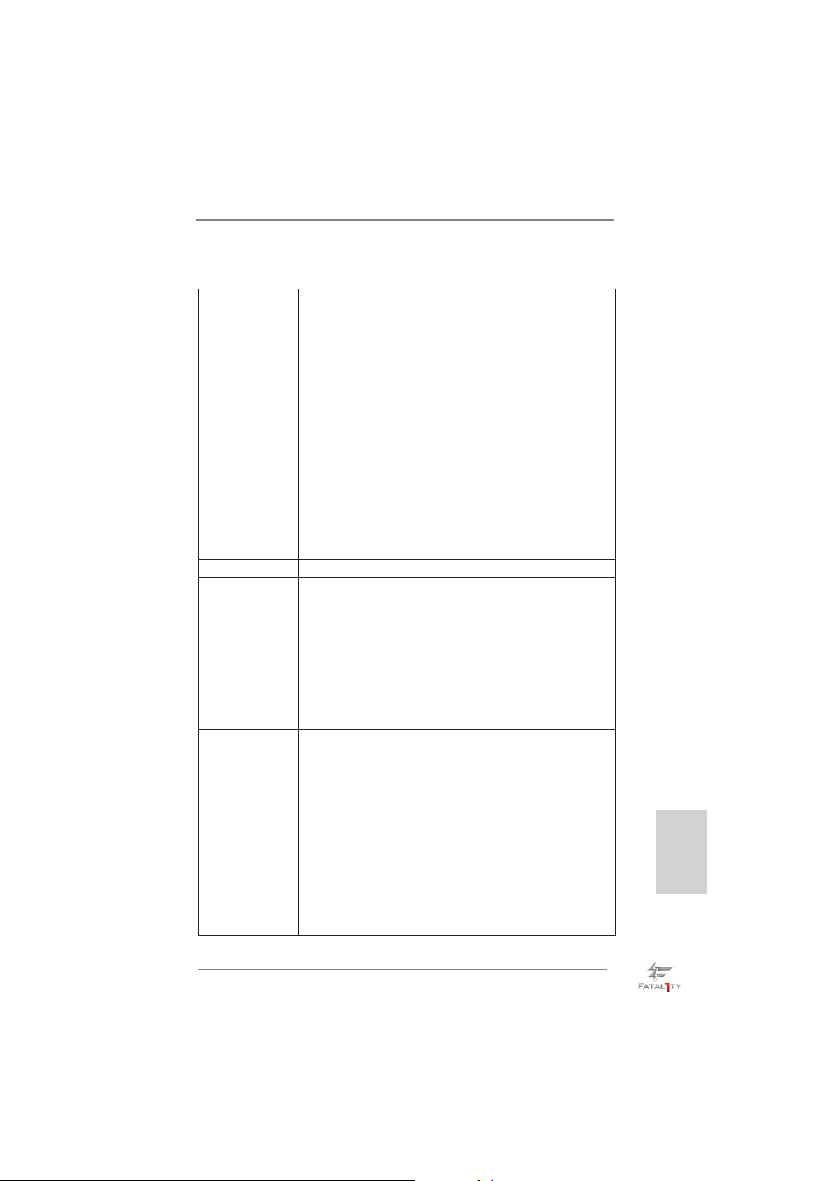
1.2 Spécifications
Format - Facteur de forme ATX:
12.0 pouces x 9.6 pouces, 30.5 cm x 24.4 cm
- Design de condensateur Premium Gold (condensateurs
polymère conducteur de qualité supérieure 100% fabriqués
au Japon)
CPU - Prend en charge les processeurs Intel
2ème et 3ème génération sur socket LGA1155
- Conception Digi Power
- 16 + 8 Power Phase conception
- Prend en charge la technologie Intel
- Prise en charge des unités centrales non verrouillées de
série K
- Prise en charge de la technologie Hyper-Threading
(voir ATTENTION 1)
- Prend en charge les technologies Intel
Connect avec processeur Intel
Chipsets - Intel® Z77
Mémoire - Compatible avec la Technologie de Mémoire à Canal
Double (voir ATTENTION 2)
- 4 x slots DIMM DDR3
- Supporter DDR3 2800+(OC)/2400(OC)/2133(OC)/1866(OC)
/1600/1333/1066 non-ECC, sans amortissement mémoire
- Capacité maxi de mémoire système: 32GB
(voir ATTENTION 3)
- Prend en charge le profi l de mémoire extrême Intel
1.3/1.2
Slot d’extension - 2 x slots PCI Express 3.0 x16 (PCIE2/PCIE4 : simple à x16
(PCIE2) / x8 (PCIE4) ou double en mode x8/x8)
(voir ATTENTION 4)
* PCIE 3.0 n’est pris en charge qu’avec le processeur Intel
Ivy Bridge. Avec le processeur Intel® Sandy Bridge, seul
PCIE 2.0 est pris en charge.
- 1 x slot PCI Express 2.0 x16 (PCIE5 : mode x4)
- 2 x slots PCI Express 2.0 x1
- 2 x slots PCI
- Prend en charge AMD Quad CrossFireX
CrossFireX
TM
et CrossFireX
TM
- Prend en charge NVIDIA® Quad SLITM et SLI
®
CoreTM i7 / i5 / i3
®
Turbo Boost 2.0
®
®
Rapid Start et Smart
Ivy Bridge CPU
TM
, 3-Way
®
(XMP)
TM
®
Français
Fatal1ty Z77 Professional Series Motherboard
77
Page 78
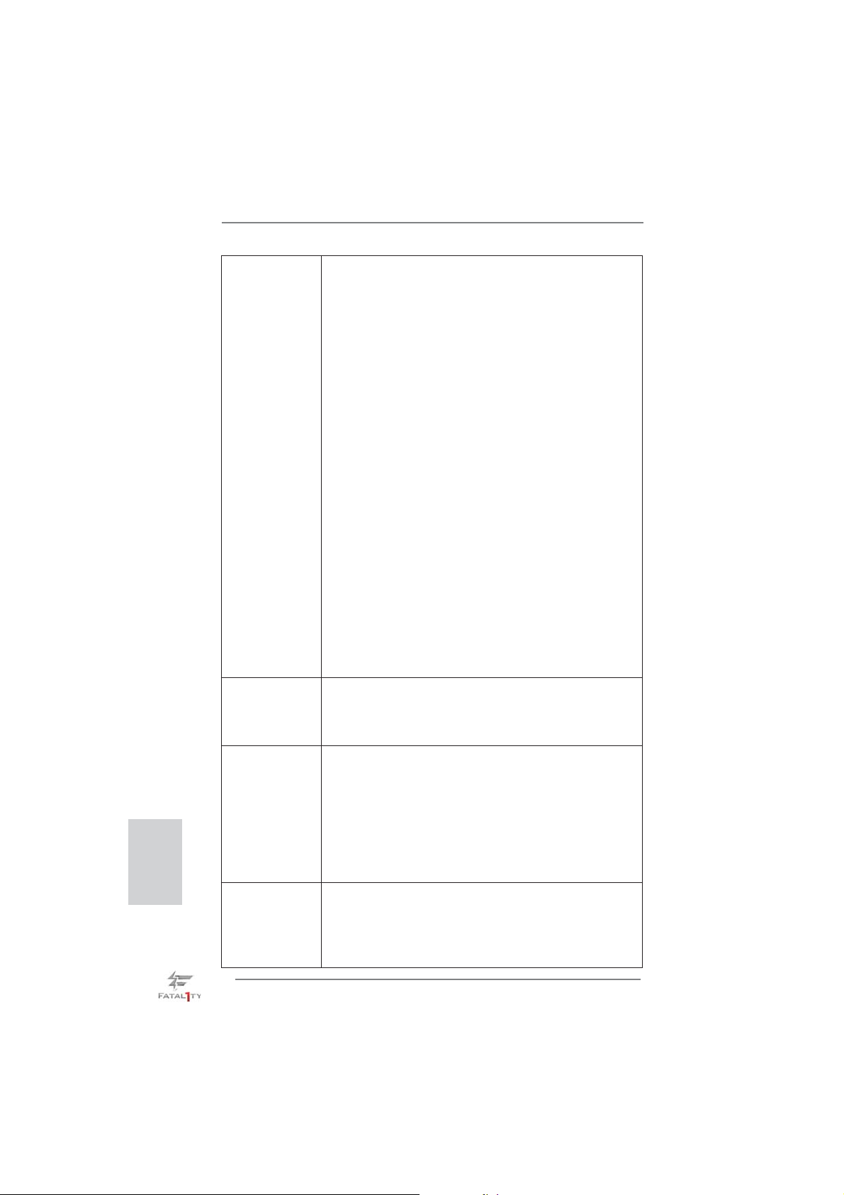
Français
VGA sur carte * Intel® HD Graphics avec visuels intégrés (Built-in Visuals) et
les sorties VGA sont uniquement pris en charge par les
processeurs à GPU intégré.
- Supporte Intel
Sync Video, Intel
Technology, Intel
®
HD Graphics Built-in Visuals: Intel® Quick
®
InTruTM 3D, Intel® Clear Video HD
®
HD Graphics 2500/4000, Intel® Advanced
Vector Extensions (AVX)
- Pixel Shader 5.0, DirectX 11 avec CPU Intel® Ivy Bridge,
Pixel Shader 4.1, DirectX 10.1 avec CPU Intel® Sandy
Bridge
- Mémoire partagée max 1760MB (voir ATTENTION 5)
- Output de VGA Duel: supporter HDMI et DisplayPort ports
par les controleurs de display independents
- Prend en charge le HDMI 1.4a avec une résolution
maximale jusqu’à 1920x1200 @ 60Hz
- Prend en charge le DisplayPort avec une résolution
maximale jusqu’à 2560x1600 @ 60Hz
- Prend en charge Lip Sync, Deep Color (12bpc), xvYCC et
HBR (High Bit Rate Audio : Audio à haut débit binaire) avec
HDMI (Moniteur compatible HDMI requis)
(voir ATTENTION 6)
- Prise en charge de la fonction HDCP avec ports HDMI et
DisplayPort
- Supporter 1080p Blu-ray(BD)/ lecteur de HD-DVD avec
ports HDMI et DisplayPort
Audio - 7,1 CH HD Audio avec protection de contenu
(Realtek ALC898 Audio Codec)
- Prise en charge de l’audio Premium Blu-ray
- Prend en charge THX TruStudio
TM
LAN - PCIE x1 Gigabit LAN 10/100/1000 Mb/s
- Broadcom BCM57781
- Support du Wake-On-LAN
- Prend en charge la norme Energy Effi cient Ethernet
(Ethernet à effi cacité énergétique) 802.3az
-
Prend en charge le Dual LAN avec la fonction Teaming
(pairage)
- Supporte PXE
Panneau arrière I/O Panel
- 1 x port clavier/souris PS/2
- 1 x port HDMI
- 1 x DisplayPort
- 1 x port de sortie optique SPDIF
78
Fatal1ty Z77 Professional Series Motherboard
Page 79
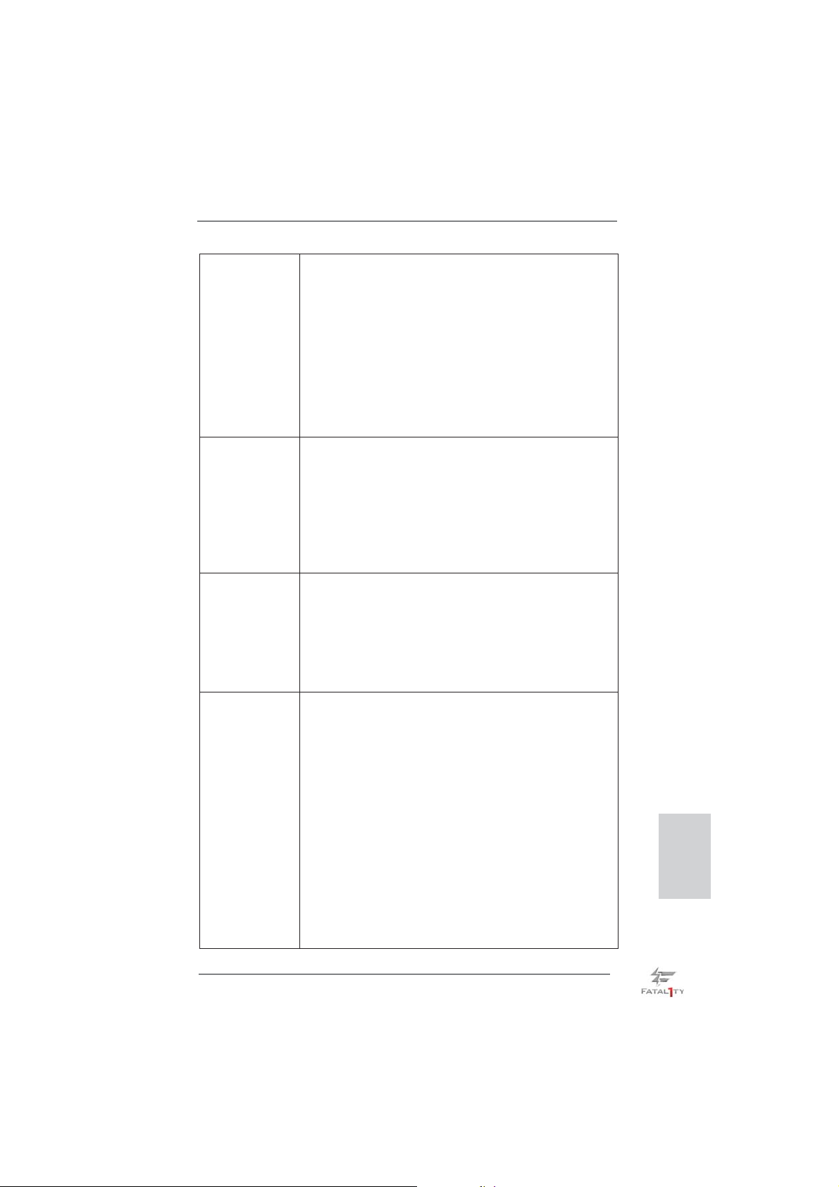
- 5 x ports USB 2.0 par défaut
- 1 x Fatal1ty port souris (USB 2.0)
- 1 x Connecteur eSATA3
- 6 x ports USB 3.0 par défaut
- 2 x ports LAN RJ-45 avec LED (ACT/LED CLIGNOTANTE
et LED VITESSE)
- 1 x port IEEE 1394
- 1 x interrupteur d’effacement du CMOS avec LED
- Prise HD Audio: Haut-parleur arrière / Central /Basses /
Entrée Ligne / Haut-parleur frontal / Microphone
(voir ATTENTION 7)
SATA 3 - 2 x connecteurs SATA3 6,0 Gb/s par Intel® Z77, prennent en
charge les fonctions RAID (RAID 0, RAID 1, RAID 5, RAID
10, Intel Rapid Storage et Intel Smart Response), NCQ,
AHCI et Hot Plug (Branchement à chaud)
- 4 x connecteurs SATA3 6,0 Gb/s par ASMedia ASM1061,
prennent en charge les fonctions NCQ, AHCI et Hot Plug
(Branchement à chaud) (le connecteur SATA3_A4 est
partagé avec le port eSATA3)
USB 3.0 - 2 x ports USB3.0 à l’arrière par Intel
®
Z77, prennent en
charge USB 1.0/2.0/3.0 jusqu’à 5 Gb/s
- 4 x ports USB3.0 à l’arrière par Etron EJ188H, prennent en
charge USB 1.0/2.0/3.0 jusqu’à 5 Gb/s
- 1 x barrette USB3.0 en façade (prend en charge 2 ports
USB 3.0) par Intel
®
Z77, prend en charge USB 1.0/2.0/3.0
jusqu’à 5 Gb/s
Connecteurs - 4 x connecteurs SATA2, prennent en charge un taux de
transfert de données pouvant aller jusqu’à 3.0Go/s,
supporte RAID (RAID 0, RAID 1, RAID 5, RAID 10, Intel
Rapid Storage et Intel Smart Response), NCQ, AHCI et
Hot Plug (Branchement à chaud)
- 6 x connecteurs SATA3, prennent en charge un taux de
transfert de données pouvant aller jusqu’à 6.0Go/s
- 1 x ATA133 IDE connecteurs
(prend en charge jusqu’à 2 périphériques IDE)
- 1 x Port Disquette
- 1 x En-tête du module infrarouge
- 1 x En-tête de port COM
- 1 x Connecteur HDMI_SPDIF
- 1 x Connecteur IEEE 1394
- 1 x Connecteur de LED d’alimentation
Français
Fatal1ty Z77 Professional Series Motherboard
79
Page 80
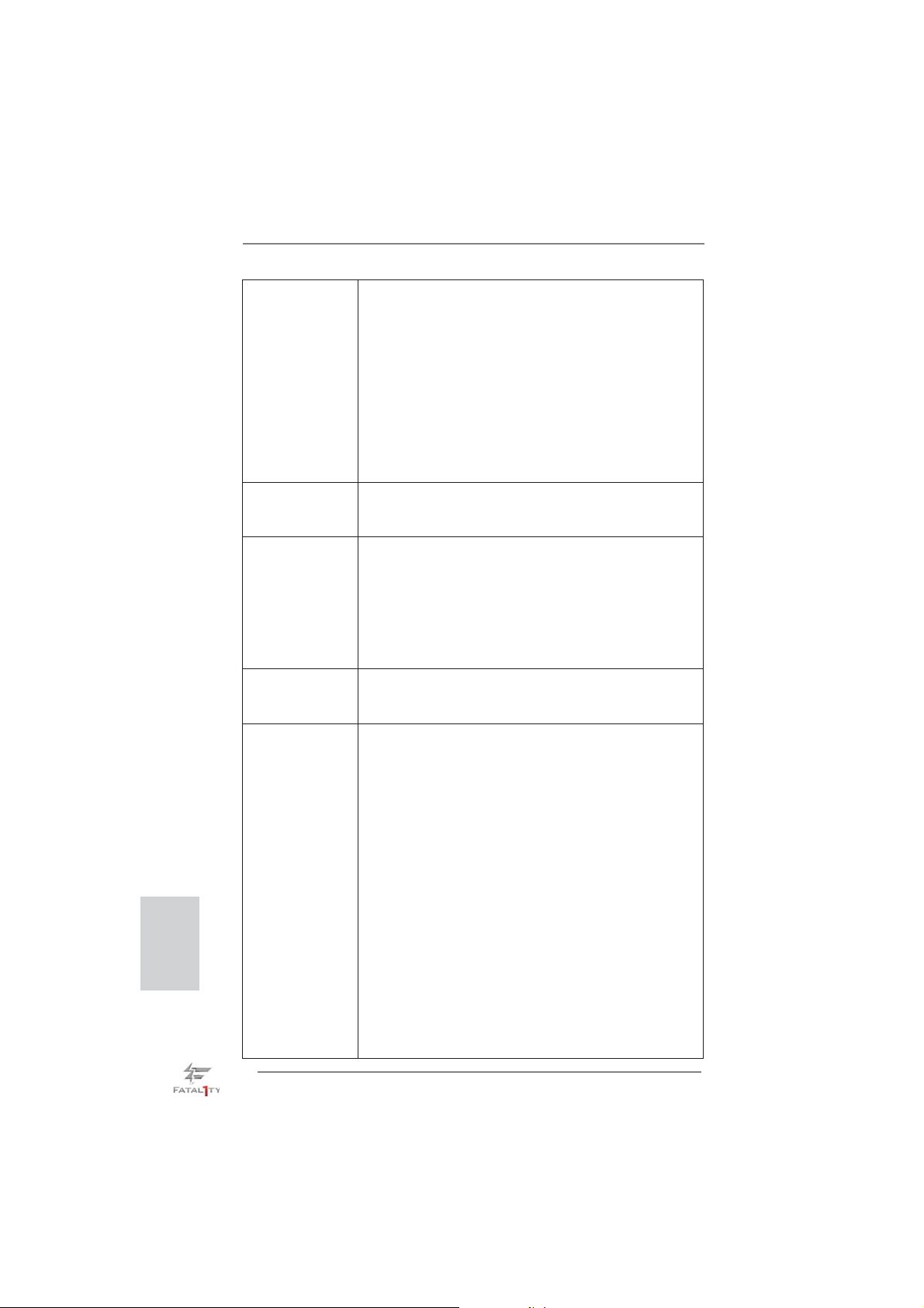
Français
- Connecteur pour ventilateur de CPU/Châssis/pouvoir
Ventilateur
- br. 24 connecteur d’alimentation ATX
- br. 8 connecteur d’alimentation 12V ATX
- Connecteurs audio internes
- Connecteur audio panneau avant
- 2 x En-tête USB 2.0 (prendre en charge 4 ports USB 2.0
supplémentaires)
- 1 x En-tête USB 3.0 (prendre en charge 2 ports USB 3.0
supplémentaires)
- 1 x Dr. Debug (LED de débogage à 7 segments)
Interrupteur - 1 x interrupteur d’effacement du CMOS avec LED
rapide - 1 x interrupteur d’alimentation avec LED
- 1 x interrupteur de réinitialisation avec LED
BIOS - 64Mb AMI UEFI Legal BIOS avec support GUI
- Support du “Plug and Play”
- Compatible pour événements de réveil ACPI 1.1
- Gestion jumperless
- Support SMBIOS 2.3.1
- CPU Core, IGPU, DRAM, 1.8V PLL, VTT, VCCSA Tension
Multi-ajustement
CD d’assistance - Pilotes, utilitaires, logiciel anti-virus (version d’évaluation),
CyberLink MediaEspresso 6.5 Trial, Suite multimédia
ASRock MAGIX - OEM
Caractéristique - F-Stream (voir ATTENTION 8)
unique - ASRock l’Instant Boot
- ASRock Instant Flash (voir ATTENTION 9)
- Chargeur ASRock APP (voir ATTENTION 10)
- ASRock SmartView (voir ATTENTION 11)
- ASRock XFast USB (voir ATTENTION 12)
- ASRock XFast LAN (voir ATTENTION 13)
- ASRock XFast RAM (voir ATTENTION 14)
- ASRock Crashless BIOS (voir ATTENTION 15)
- Lucid Virtu Universal MVP (voir ATTENTION 16)
* Lucid Virtu Universal MVP est uniquement pris en charge
par les processeurs à GPU intégré.
- L’accélérateur hybride:
- Contrôle direct de la fréquence CPU
(voir ATTENTION 17)
- ASRock U-COP (voir ATTENTION 18)
- Garde d’échec au démarrage (B.F.G.)
- Combo Cooler Option (C.C.O.) (voir ATTENTION 19)
80
Fatal1ty Z77 Professional Series Motherboard
Page 81
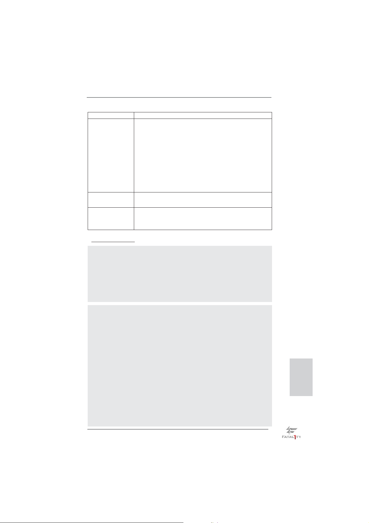
- DEL veilleuse
Surveillance - Détection de la température de l’UC
système - Mesure de température de la carte mère
- Tachéomètre ventilateur processeur/châssis/pouvoir
ventilateur
- Ventilateur silencieux pour unité centrale/châssis (permet le
réglage automatique de la vitesse du ventilateur pour
châssis, selon la température de l’unité centrale)
- Commande de ventilateur CPU/Châssis à plusieurs
vitesses
- Monitoring de la tension: +12V, +5V, +3.3V, Vcore
OS - Microsoft
®
Windows® 7 / 7 64-bit / VistaTM / Vista
TM
64-bit
/ XP / XP 64-bit (voir ATTENTION 20)
Certifi cations - FCC, CE, WHQL
- Prêt pour ErP/EuP (alimentation Prêt pour ErP/EuP requise)
(voir ATTENTION 21)
* Pour de plus amples informations sur les produits, s’il vous plaît visitez notre site web:
http://www.asrock.com
ATTENTION
Il est important que vous réalisiez qu’il y a un certain risque à effectuer
l’overclocking, y compris ajuster les réglages du BIOS, appliquer la technologie
Untied Overclocking, ou utiliser des outils de tiers pour l’overclocking. L’overclocking
peut affecter la stabilité de votre système, ou même causer des dommages aux
composants et dispositifs de votre système. Si vous le faites, c’est à vos frais et
vos propres risques. Nous ne sommes pas responsables des dommages possibles
causés par l’overclocking.
ATTENTION!
1. En ce qui concerne le paramétrage “Hyper-Threading Technology”,
veuillez consulter la page 73 du manuel de l’utilisateur sur le CD tech-
nique.
2. Cette carte mère supporte la Technologie de Mémoire à Canal Double.
Avant d’intégrer la Technologie de Mémoire à Canal Double, assurezvous de bien lire le guide d’installation des modules mémoire en page 19
pour réaliser une installation correcte.
3. Du fait des limites du système d’exploitation, la taille mémoire réelle
réservée au système pourra être inférieure à 4 Go sous Windows
VistaTM / XP. Avec Windows® OS avec CPU 64 bits, il n’y a pas ce genre
de limitation. Vous pouvez utiliser ASRock XFast RAM pour accéder à la
mémoire que Windows® ne peut pas utiliser.
4. PCIE2 et PCIE4 prend en charge une vitesse pouvant atteindre Gen 3.
Pour pouvoir utiliser PCI Express en vitesse Gen 3, vous devez installer
le processeur Ivy Bridge. Si vous installez le processeur Sandy Bridge,
PCI Express ne fonctionnera qu’en vitesse PCI Express Gen 2.
Fatal1ty Z77 Professional Series Motherboard
®
7 /
Français
81
Page 82

Français
5. La dimension maximum du memoire partage est defi nie par le vendeur
de jeu de puces et est sujet de changer. Veuillez verifi er la Intel
®
website
pour les informations recentes SVP.
6. xvYCC et Deep Color ne sont pris en charge que sous Windows® 7 64-
bit / 7. Le mode Deep Color ne sera activé que si le moniteur prend en
charge 12bpc en EDID. HBR est pris en charge sous Windows
TM
7 / Vista
64-bit / VistaTM.
®
7 64-bit /
7. Pour l’entrée microphone, cette carte mère supporte les deux modes
stéréo et mono. Pour la sortie audio, cette carte mère supporte les
modes 2-canaux, 4-canaux, 6-canaux et 8-canaux. Veuillez vous référer
au tableau en page 5 pour effectuer la bonne connexion.
8. F-Stream est un utilitaire tout-en-un qui permet de régler précisément
différentes fonctions du système, via une interface facile à utiliser,
incluant Moniteur de périphériques, Contrôle du ventilateur, Overclocking,
OC DNA et IES. Dans Moniteur de périphériques, il affi che les valeurs
principales de votre système. Dans Contrôle du ventilateur, il affi che
la vitesse du ventilateur et la température, que vous pouvez ajuster.
Dans Overclocking, vous pouvez overclocker la fréquence du CPU pour
améliorer les performances du système. Dans OC DNA, vous pouvez
enregistrer vos réglages OC dans un profi l et les partager avec vos amis.
Vos amis pourront alors installer le profi l OC sur leur système pour utiliser
les mêmes réglages OC. Dans IES (Intelligent Energy Saver – Fonction
intelligente d’économie d’énergie), le contrôleur de la tension peut réduire
le nombre de phases de sortie pour améliorer le fonctionnement lorsque
les cores du CPU ne sont pas utilisées, sans diminuer les performances
de l’ordinateur.
9. O ASRock Instant Flash é um utilitário de fl ash do BIOS incorporado
na memória Flash ROM. Esta prática ferramenta de actualização do
BIOS permite-lhe actualizar o BIOS do sistema sem necessitar de entrar
nos sistemas operativos, como o MS-DOS ou o Windows
®
. Com este
utilitário, poderá premir a tecla <F6> durante o teste de arranque POST
ou premir a tecla <F2> para exibir o menu de confi guração do BIOS para
aceder ao ASRock Instant Flash. Execute esta ferramenta para guardar
o novo fi cheiro de BIOS numa unidade fl ash USB, numa disquete ou
num disco rígido, em seguida, poderá actualizar o BIOS com apenas
alguns cliques sem ter de utilizar outra disquete ou outro complicado
utilitário de fl ash. Note que a unidade fl ash USB ou a unidade de disco
rígido devem utilizar o sistema de fi cheiros FAT32/16/12.
10. Si vous désirez un moyen plus rapide et moins contraignant de recharger
vos appareils Apple tels que iPhone/iPad/iPod Touch, ASRock a préparé
pour vous la solution idéale - le chargeur ASRock APP. Il suffi t d’installer
le pilote du chargeur APP, et vous pourrez recharger rapidement votre
iPhone à partir de votre ordinateur, jusqu’à 40% plus vite qu’avant. Le
chargeur ASRock APP vous permet de charger rapidement et simultanément plusieurs appareils Apple, et le chargement continu est même
pris en charge lorsque le PC passe en mode Veille (S1), Suspension à la
RAM (S3), hibernation (S4) ou hors tension (S5). Lorsque le pilote du
82
Fatal1ty Z77 Professional Series Motherboard
Page 83

chargeur APP est installé, vous découvrez un mode de mise en charge
tout à fait inédit.
Site web ASRock : http://www.asrock.com/Feature/AppCharger/index.asp
11.
SmartView, une nouvelle fonction du navigateur Internet, est une page
de démarrage intelligente de IE, comportant à la fois vos sites Internet
les plus visités, votre historique, vos amis Facebook et l’actualité en
temps réel, le tout sur une vue optimisée pour une expérience de l’Internet
encore plus personnelle. Les cartes mères ASRock sont équipées en
exclusivité de l’utilitaire SmartView, ce qui vous permet de garder le
contact avec vos amis itinérants. Pour utiliser la fonction SmartView,
veuillez vous assurez que votre version de système d’exploitation est
®
Windows
navigateur IE8. Site Internet ASRock : http://www.asrock.com/Feature/
SmartView/index.asp
12. ASRock XFast USB permet d’améliorer les performances de votre périphérique de stockage USB. Les performances réelles dépendent des
propriétés du périphérique.
13. ASRock XFast LAN fournit un accès Internet plus rapide, avec les avantages suivants. Priorisation d’application LAN : Vous pouvez confi gurer
votre priorité d’application idéalement et/ou ajouter des nouveaux programmes. Latence plus basse dans les jeux : Après avoir réglé la priorité
de jeux en ligne plus haute, cela peut réduire la latence dans les jeux.
Forme du trafi c : Vous pouvez regarder des vidéos HD YouTube et té-
lécharger simultanément des fi chiers. Analyse en temps réel de vos don-
nées : Avec la fenêtre d’état, vous pouvez facilement reconnaître les fl ux
de données que vous êtes en train de transférer.
14. ASRock XFast RAM est une nouvelle fonction intégrée à l’utilitaire FStream. Il utilise à sa pleine capacité l’espace mémoire que les processeurs du système d’exploitation Windows OS 32-bit ne peuvent pas
utiliser. ASRock XFast RAM diminue le temps de chargement des sites
Internet précédemment visités, rendant la navigation sur le web plus
rapide que jamais. Il rend également l’utilisation de Adobe Photoshop 5
fois plus rapide. Un autre avantage indéniable de ASRock XFast RAM
est qu’il réduit la fréquence d’accès à vos SSD ou HDD afi n d’accroitre
leur durée de vie utile.
15. ASRock Crashless BIOS permet aux utilisateurs de mettre à jour leur
BIOS sans qu’ils aient à craindre un plantage ou une défaillance. Si
l’alimentation venait à être coupée durant la mise à jour du BIOS, ASRock Crashless BIOS terminera automatiquement la mise à jour du BIOS
une fois le courant rétabli. Veuillez noter que les fi chiers BIOS doivent
être placés dans le répertoire racine de votre disque USB. Seuls les
ports USB2.0 sont compatibles avec cette fonction.
16. VIRTU Universal MVP intègre toutes les fonctionnalités de base de la
technologie Virtu Universal, qui virtualise GPU intégrée et GPU discrète
pour des fonctionnalités optimales. Il est également doté de la fonction
Virtual Vsync
les avantages de la technologie HyperFormance, et VIRTU Universal
7 / 7 64 bits / VistaTM / VistaTM 64 bits, et que vous utilisez le
TM
pour une qualité visuelle sans compromis. Ajoutez à cela
Français
Fatal1ty Z77 Professional Series Motherboard
83
Page 84

MVP vous permettra d’obtenir des performances de jeu inégalées en
réduisant intelligemment les tâches redondantes du rendu lors du fl ux
entre le CPU, le GPU de la carte graphique et l’écran.
17. Même si cette carte mère offre un contrôle sans souci, il n’est pas re-
commandé d’y appliquer un over clocking. Des fréquences de bus CPU
autres que celles recommandées risquent de rendre le système instable
ou d’endommager le CPU et la carte mère.
18. Lorsqu’une surchauffe du CPU est détectée, le système s’arrête automa-
tiquement. Avant de redémarrer le système, veuillez vérifi er que le ven-
tilateur d’UC sur la carte mère fonctionne correctement et débranchez le
cordon d’alimentation, puis rebranchez-le. Pour améliorer la dissipation
de la chaleur, n’oubliez pas de mettre de la pâte thermique entre le CPU
le dissipateur lors de l’installation du PC.
19. Le Combo Cooler Option (C.C.O.) offre un choix fl exible pour adopter
trois types différents de refroidisseur sde CPU, les sockets LGA 775,
LGA 1155 et LGA 1156. Veuillez noter que tous les ventilateurs de CPU
775 et 1156 ne peuvent pas être utilisés.
20. ASRock XFast RAM n’est pas pris en charge par Microsoft
XP / XP 64-bit. Les technologie Intel® Smart Connect et ports Intel® USB
3.0 n’est pas pris en charge par Microsoft® Windows® VistaTM / VistaTM 64bit / XP / XP 64-bit.
21. EuP, qui signifi e Energy Using Product (Produit Utilisant de l’Energie),
est une disposition établie par l’Union Européenne pour défi nir la con-
sommation de courant pour le système entier. Conformément à la norme
EuP, le courant CA total du système entier doit être inférieur à 1 W en
mode d’arrêt. Pour être conforme à la norme EuP, une carte mère EuP
et une alimentation EuP sont requises. Selon les suggestions d’Intel’,
l’alimentation électrique EuP doit correspondre à la norme, qui est que
l’effi cacité électrique de 5v en mode de veille doit être supérieure à 50%
pour 100 mA de consommation de courant. Pour choisir une alimentation
électrique conforme à la norme EuP, nous vous recommandons de consulter votre fournisseur de courant pour plus de détails.
®
Windows®
Français
84
Fatal1ty Z77 Professional Series Motherboard
Page 85
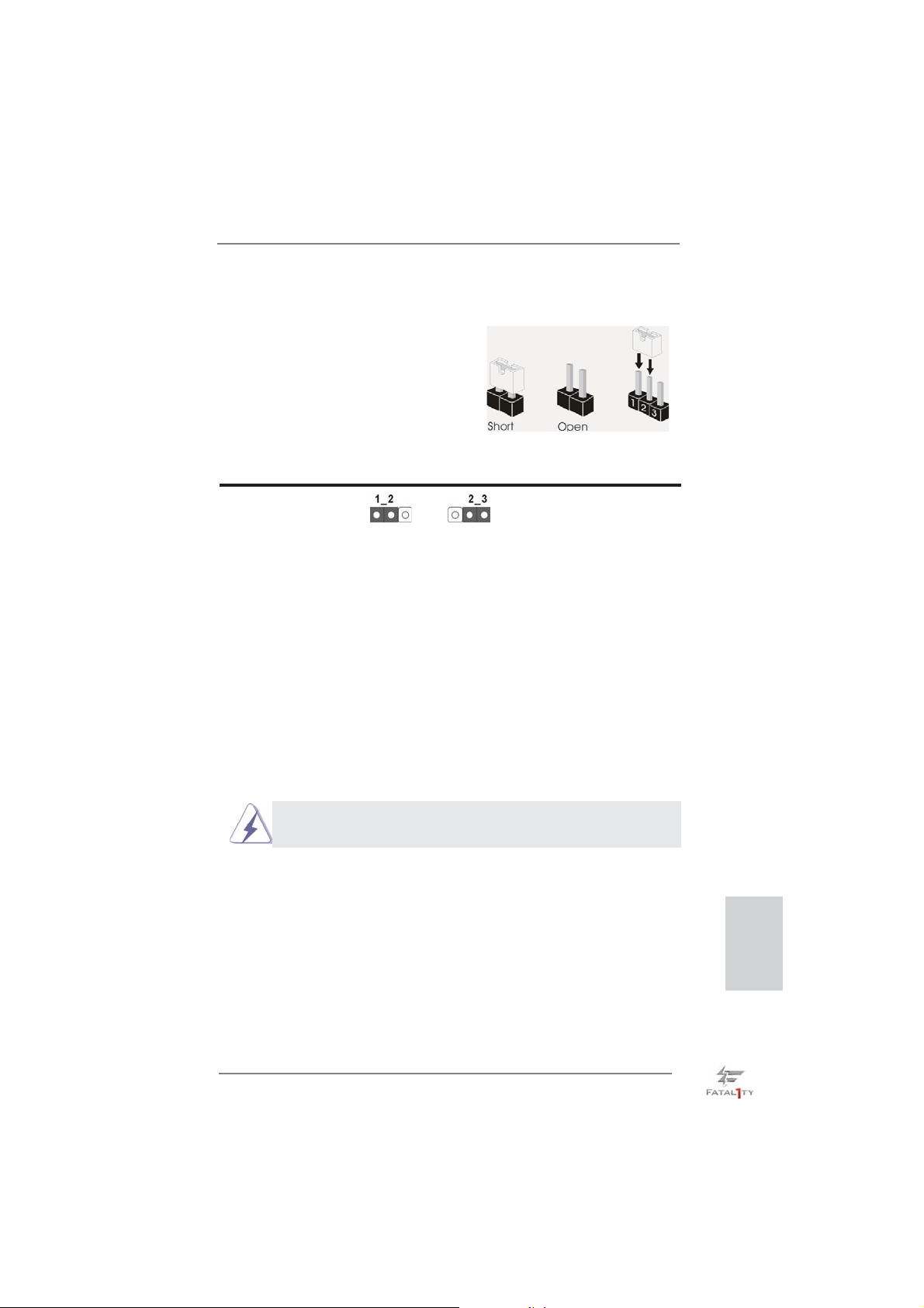
1.3 Réglage des cavaliers
L’illustration explique le réglage des cavaliers. Quand un capuchon est placé sur les
broches, le cavalier est « FERME ». Si aucun capuchon ne relie les broches,le cavalier est « OUVERT ». L’illustration montre un
cavalier à 3 broches dont les broches 1 et 2
sont « FERMEES » quand le capuchon est
placé sur ces 2 broches.
Le cavalier Description
Effacer la CMOS
(CLRCMOS1)
(voir p.4 fi g. 27)
Remarque :
Paramètres
par défaut
CLRCMOS1 vous permet d’effacer les données du CMOS. Pour effacer
et réinitialiser les paramètres du système à la confi guration originale,
veuillez éteindre l’ordinateur et débrancher le cordon d’alimentation de
la prise de courant. Après 15 secondes, utilisez un couvercle de jumper
pour court-circuiter les broches pin2 et pin3 de CLRCMOS1 pendant
secondes. Veuillez cependant ne pas effacer le CMOS immédiatement
a
près avoir mis à jour le BIOS. Si vous avez besoin d’effacer le CMOS
après avoir mis à jour le BIOS, vous devez allumer en premier le
système, puis l’éteindre avant de continuer avec l’opération d’effacement
du CMOS. Veuillez noter que le mot de passe, la date, l’heure, le profi l
par défaut de l’utilisateur, 1394 GUID et l’adresse MAC seront effacés
seulement si la batterie du CMOS est enlevée.
Effacer la
CMOS
5
Le commutateur Effacer CMOS présente la même fonction que le
cavalier Effacer CMOS.
Fatal1ty Z77 Professional Series Motherboard
Français
85
Page 86
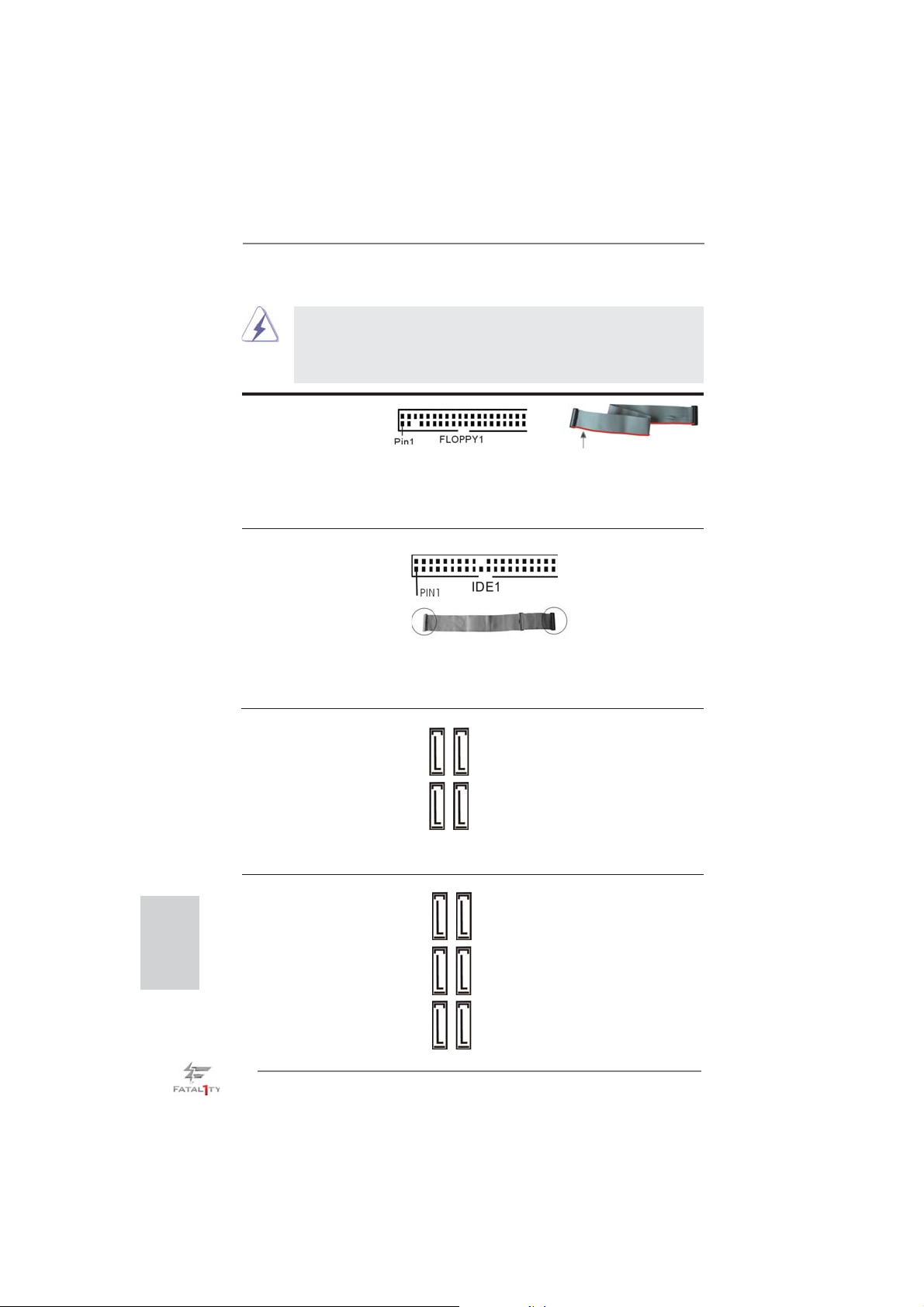
1.4 En-têtes et Connecteurs sur Carte
Connecteur du lecteur
de disquette
(FLOPPY1 br. 33)
(voir p.4 No. 30)
Note: Assurez-vous que le côté avec fi l rouge du câble est bien branché sur le
côté Broche1 du connecteur.
Connecteur IDE primaire (noir)
(IDE1 br. 39, voir p.4 No. 8)
connecteur bleu connecteur noir
vers la carte mère vers le disque dur
Câble ATA 66/100/133 80 conducteurs
Note: Veuillez vous reporter aux instructions du fabricant de votre IDE périphérique
pour les détails.
Connecteurs Série ATA2 Ces quatre connecteurs Série
(SATA2_2_3: voir p.4 No. 14)
(SATA2_4_5: voir p.4 No. 15)
les périphériques de stockage
internes. L’interface SATA2
actuelle permet des taux
transferts de données pouvant
aller jusqu’à 3,0 Gb/s.
Les en-têtes et connecteurs sur carte NE SONT PAS des cavaliers.
NE PAS placer les capuchons de cavalier sur ces en-têtes et connecteurs. Le fait de placer les capuchons de cavalier sur les en-têtes
et connecteurs causera à la carte mère des dommages irréversibles!
le côté avec fi l rouge côté
Broche1
ATA2 (SATA2) prennent en
SATA2_2 SATA2_3
charge les câbles SATA pour
SATA2_4 SATA2_5
Français
Connecteurs Série ATA3 Ces six connecteurs Série
(SATA3_0_1: voir p.4 No. 13)
(SATA3_A1_A2: voir p.4 No. 12)
(SATA3_A3_A4: voir p.4 No. 11)
internes. L’interface SATA3
ATA3 (SATA3) prennent en
SATA3_A3 SATA3_A4
charge les câbles SATA pour
les périphériques de stockage
SATA3_A1 SATA3_A2
actuelle permet des taux
transferts de données pouvant
aller jusqu’à 6,0 Gb/s. Si vous
SATA3_0 SATA3_1
installez le disque dur sur le
86
Fatal1ty Z77 Professional Series Motherboard
Page 87
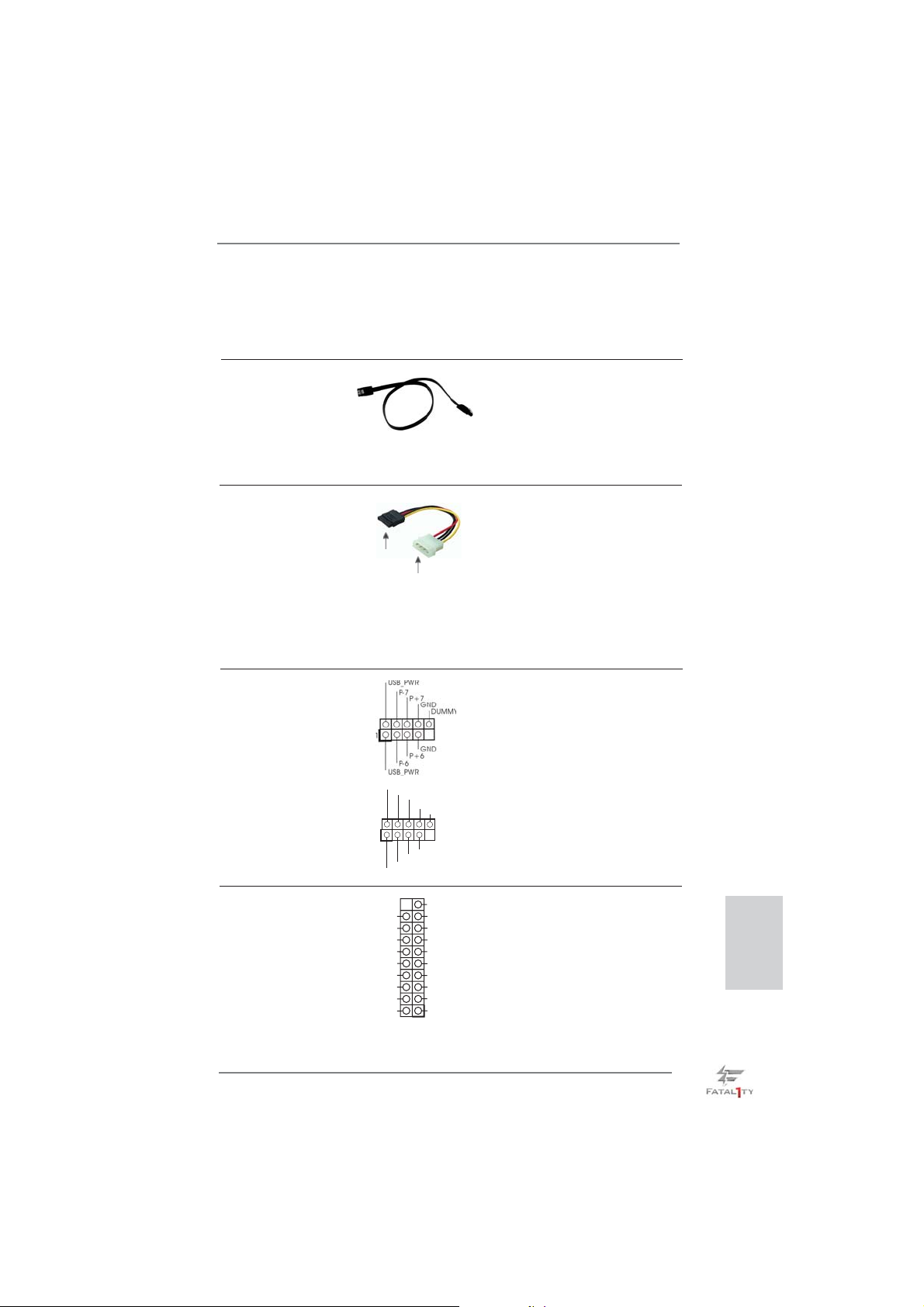
port eSATA3 sur le panneau
E/S arrière, le connecteur
SATA3_A4 interne ne
fonctionne pas.
Câble de données Toute cote du cable de data
Série ATA (SATA) SATA peut etre connecte au
(en option)
disque dur SATA / SATA2 /
SATA3 ou au connecteur SATA2
/ SATA3 sur la carte
mere.
Cordon d’alimentation Veuillez connecter l’extrémité
Série ATA (SATA) noire du cordon d’alimentation
(en option)
SATA sur le connecteur
d’alimentation sur chaque unité.
Connectez ensuite l’extrémité
blanche du cordon
d’alimentation SATA sur le
connecteur d’alimentation de
connecter au connec-
teur
d’alimentation du
disque
dur SATA
connecter à
l’unité
d’alimentation
électrique
l’unité d’alimentation électrique.
En-tête USB 2.0 A côté des six ports USB 2.0
(USB_6_7 br. 9)
(voir p.4 No. 24)
par défaut sur le panneau E/S,
il y a deux embases USB 2.0
sur cette carte mère. Chaque
embase USB 2.0 peut prendre
en charge 2 ports USB 2.0.
(USB_8_9 br. 9)
(voir p.4 No. 25)
1
USB_PWR
P-9
P-8
USB_PWR
P+9
P+8
GND
GND
DUMMY
En-tête USB 3.0 En plus des six ports USB
(USB3_6_7 br. 19)
(voir p.4 No. 9)
3.0 par défaut sur le panneau
E/S, il y a une barrette USB 3.0
sur la carte mère. Cette barrette
USB 3.0 peut prendre en
charge deux ports USB 3.0.
Vbus
IntA_P6_SSRX-
IntA_P6_SSRX+
GND
IntA_P6_SSTX-
IntA_P6_SSTX+
GND
IntA_P6_D-
IntA_P6_D+
VbusVbus
IntA_P7_SSRX-
IntA_P7_SSRX+
GND
IntA_P7_SSTX-
IntA_P7_SSTX+
GND
IntA_P7_D-
IntA_P7_D+
DUMMY
Fatal1ty Z77 Professional Series Motherboard
Français
87
Page 88
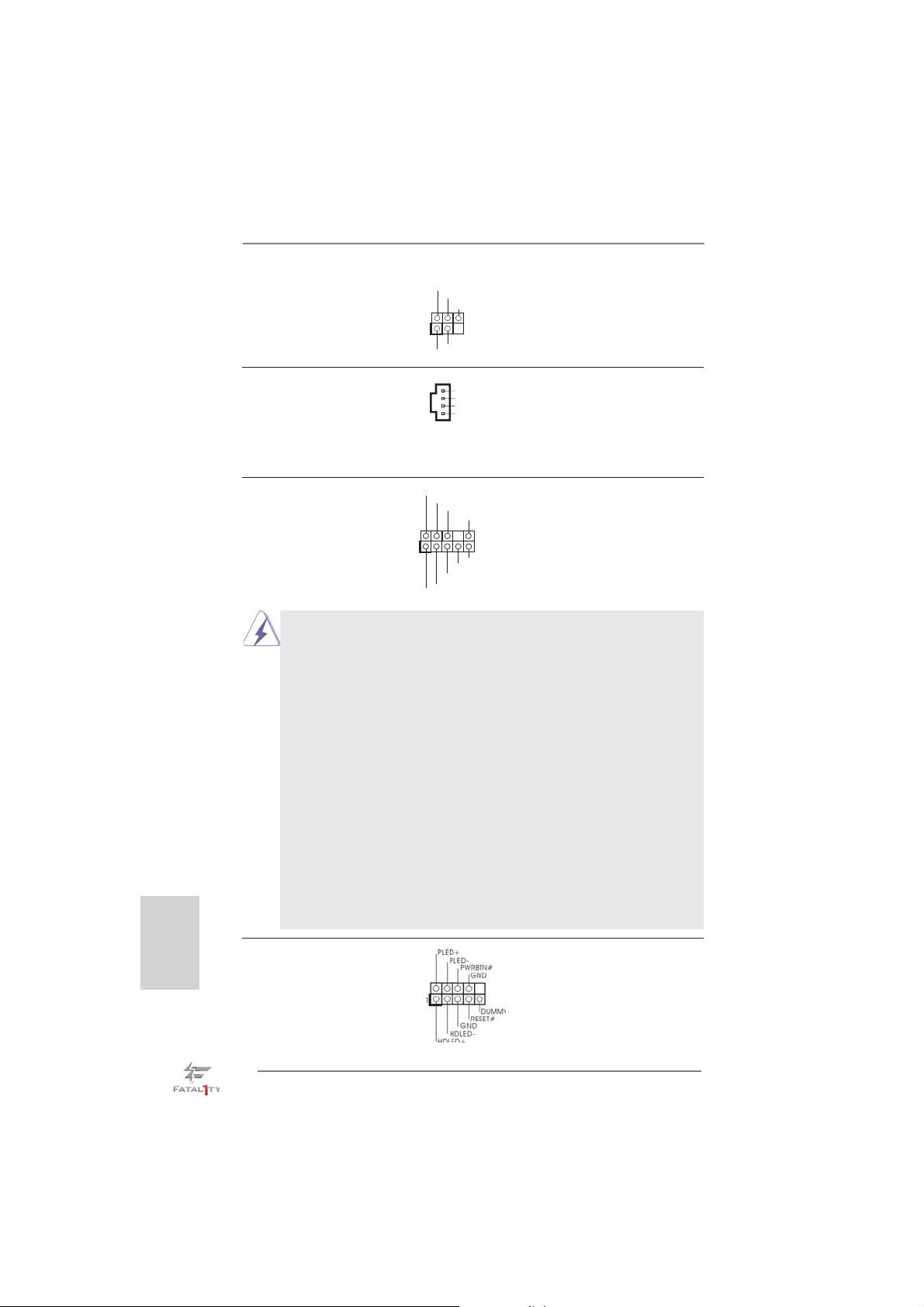
En-tête du module infrarouge Cet en-tête supporte un module
(IR1 br. 5)
infrarouge optionnel de transfert
(voir p.4 No. 29)
et de réception sans fi l.
IRTX
+5VSB
DUMMY
1
GND
IRRX
Français
Connecteurs audio internes Ils vous permettent de gérer
(CD1 br. 4)
(CD1: voir p.4 No. 42)
des entrées audio à partir de
sources stéréo comme un
CD-ROM, DVD-ROM, un tuner
CD1
CD-L
GND
GND
CD- R
TV ou une carte MPEG.
Connecteur audio panneau C’est une interface pour un
(HD_AUDIO1 br. 9)
(voir p.4 No. 32)
câble avant audio en façade qui
permet le branchement et le
contrôle commodes de
périphériques audio.
1. L’audio à haute défi nition (HDA) prend en charge la détection de fi che, mais le fi l
de panneau sur le châssis doit prendre en charge le HDA pour fonctionner
correctement. Veuillez suivre les instructions dans notre manuel et le manuel de
châssis afi n installer votre système.
2. Si vous utilisez le panneau audio AC’97, installez-le sur l’adaptateur audio
du panneau avant conformément à la procédure ci-dessous:
A. Connectez Mic_IN (MIC) à MIC2_L.
B. Connectez Audio_R (RIN) à OUT2_R et Audio_L (LIN) à OUT2_L.
C. Connectez Ground (GND) à Ground (GND).
D. MIC_RET et OUT_RET sont réservés au panneau audio HD. Vous
n’avez pas besoin de les connecter pour le panneau audio AC’97.
E. Pour activer le micro avant.
Pour les systèmes d’exploitation Windows
Sélectionnez “Mixer”. Sélectionnez “Recorder” (Enregistreur). Puis
cliquez sur “FrontMic” (Micro avant).
Pour les systèmes d’exploitation Windows
VistaTM 64 bits :
Allez sur l’onglet “FrontMic” (Micro avant) sur le Panneau de contrôle
Realtek. Ajustez “Recording Volume” (Volume d’enregistrement).
1
1
GND
GND
PRESENCE#
PRESENCE#
MIC2_R
MIC2_R
MIC2_L
MIC2_L
MIC_RET
MIC_RET
J_SENSE
J_SENSE
OUT2_R
OUT2_R
OUT_RET
OUT_RET
OUT2_L
OUT2_L
®
XP / XP 64 bits :
®
7 / 7 64 bits / VistaTM /
En-tête du panneau système Cet en-tête permet d’utiliser
(PANEL1 br. 9)
(voir p.4 No. 21)
plusieurs fonctions du panneau
système frontal.
88
Fatal1ty Z77 Professional Series Motherboard
Page 89
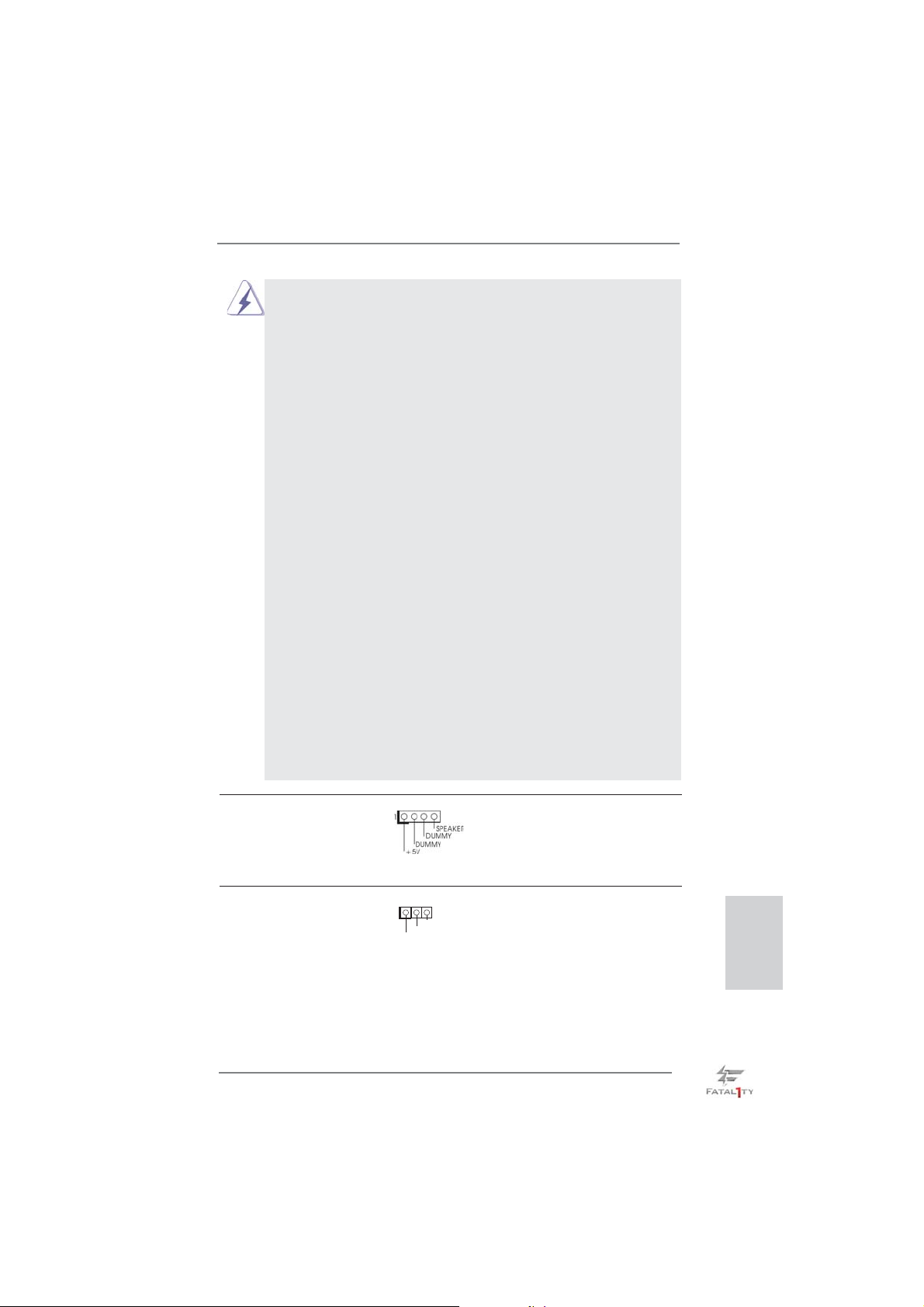
Connectez l’interrupteur d’alimentation, l’interrupteur de réinitialisation et
l’indicateur d’état du système du châssis sur cette barrette en respectant
l’affectation des broches décrite ci-dessous. Faites attention aux broches
positives et négatives avant de connecter les câbles.
PWRBTN (Interrupteur d’alimentation):
Connectez ici le connecteur d’alimentation sur le panneau avant du
châssis. Vous pouvez confi gurer la façon de mettre votre système hors
tension avec l’interrupteur d’alimentation.
RESET (Interrupteur de réinitialisation):
Connectez ici le connecteur de réinitialisation sur le panneau avant du
châssis. Appuyez sur l’interrupteur de réinitialisation pour redémarrer
l’ordinateur s’il se bloque ou s’il n’arrive pas à redémarrer normalement.
PLED (DEL alimentation système):
Connectez ici l’indicateur d’état de l’alimentation sur le panneau avant du
châssis. Ce voyant DEL est allumé lorsque le système est en marche.
Le voyant DEL clignote lorsque le système est en mode veille S1/S3. Le
voyant DEL est éteint lorsque le système est en mode veille S4 ou
lorsqu’il est éteint (S5).
HDLED (DEL activité du disque dur):
Connectez ici le voyant DEL d’activité du disque dur sur le panneau
avant du châssis. Ce voyant DEL est allumé lorsque le disque dur est en
train de lire ou d’écrire des données.
Le design du panneau avant peut varier en fonction du châssis. Un
module de panneau avant consiste principalement en : interrupteur
d’alimentation, interrupteur de réinitialisation, voyant DEL d’alimentation,
voyant DEL d’activité du disque dur, haut-parleur, etc. Lorsque vous
connectez le panneau avant de votre châssis sur cette barrette, vérifi ez
bien à faire correspondre les fi ls et les broches.
En-tête du haut-parleur Veuillez connecter le
de châssis haut-parleur de châssis sur cet
(SPEAKER1 br. 4)
(voir p.4 No. 20)
LED di accensione Collegare il LED di accensione
(PLED1 br. 3)
(voir p.4 Nr. 19)
en-tête.
chassi per indicare lo stato di
alimentazione del sistema. Il
1
PLED+
PLED+
PLED-
LED è acceso quando il sistema
è in funzione. Il LED continua a
lampeggiare in stato S1/S3. Il
LED è spento in stato S4 o S5
(spegnimento).
Fatal1ty Z77 Professional Series Motherboard
Français
89
Page 90
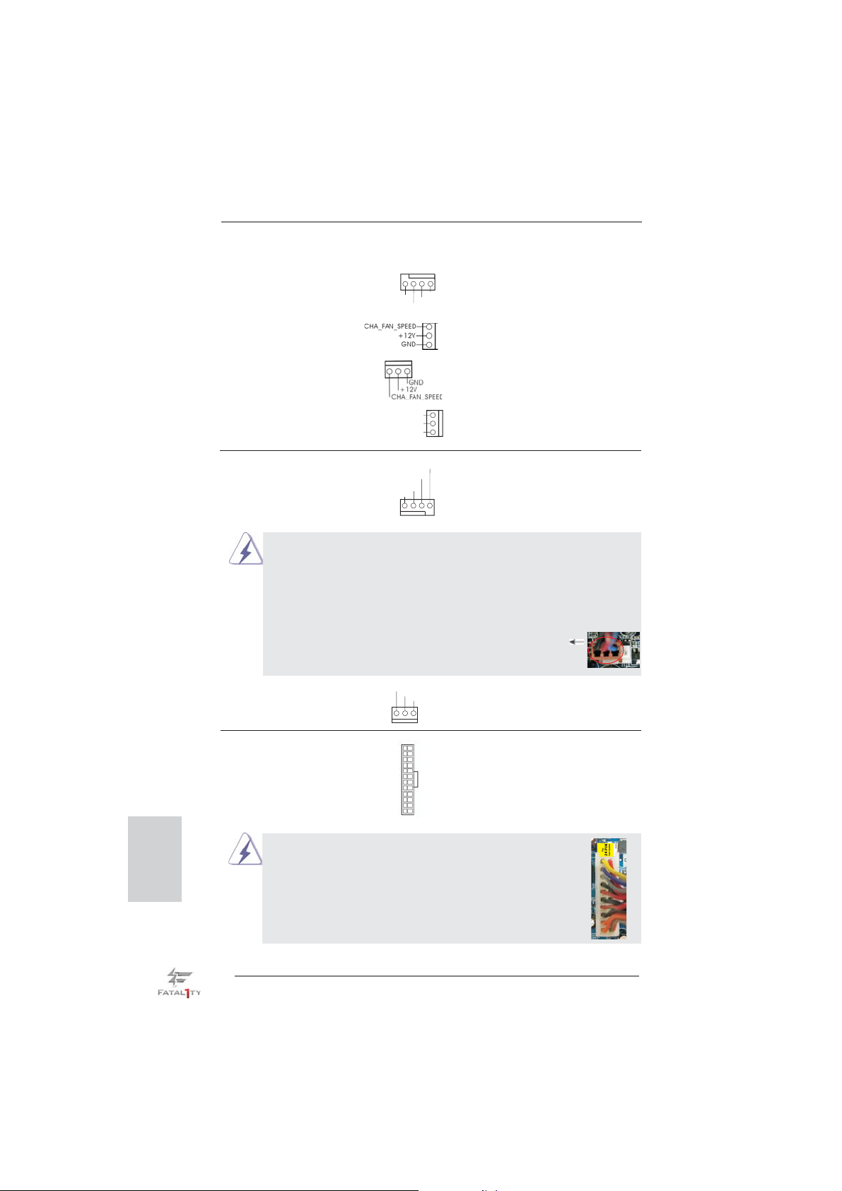
Connecteur pour châssis et ventilateur Branchez les câbles du
(CHA_FAN1 br. 4)
(voir p.4 No. 26)
correspondre le fi l noir à la
(CHA_FAN2 br. 3)
(voir p.4 No. 43)
ventilateur aux connecteurs
pour ventilateur et faites
FAN_SPEED_CONTROL
CHA_FAN_SPEED
+12V
GND
broche de terre. CHA_FAN1,
CHA_FAN2 et HA_FAN3
prennent en charge la fonction
(CHA_FAN3 br. 3)
(voir p.4 No. 22)
(PWR_FAN1 br. 3)
(voir p.4 No. 41)
contrôle du ventilateur.
PWR_FAN_SPEED
+12V
GND
Français
Connecteur du ventilateur Veuillez connecter le câble de
de l’UC ventilateur d’UC sur ce
(CPU_FAN1 br. 4)
(voir p.4 No. 3)
connecteur et brancher le fi l
noir sur la broche de terre.
FAN_SPEED_CONTROL
CPU_FAN_SPEED
+12V
GND
1 2 3 4
Bien que cette carte mère offre un support de (Ventilateur silencieux
ventilateur de CPU à 4 broches , le ventilateur de CPU à 3 broches peut
bien fonctionner même sans la fonction de commande de vitesse du
ventilateur. Si vous prévoyez de connecter le ventilateur de CPU à 3
broches au connecteur du ventilateur de CPU sur cette carte mère,
veuillez le connecter aux broches 1-3.
Installation de ventilateur à 3 broches
Broches 1-3 connectées
(CPU_FAN2 br. 3)
(voir p.4 No. 4)
En-tête d’alimentation ATX Veuillez connecter l’unité
(ATXPWR1 br. 24)
(voir p.4 No. 7)
Bien que cette carte mère fournisse un connecteur de
d’alimentation ATX sur cet en-
tête.
GND
+12V
12 124
CPU_FAN_SPEED
13
12
24
courant ATX 24 broches, elle peut encore fonctionner
si vous adopter une alimentation traditionnelle ATX 20
broches. Pour utiliser une alimentation ATX 20 broches,
branchez à l’alimentation électrique ainsi qu’aux
broches 1 et 13.
20-Installation de l’alimentation électrique ATX
1
13
90
Fatal1ty Z77 Professional Series Motherboard
Page 91
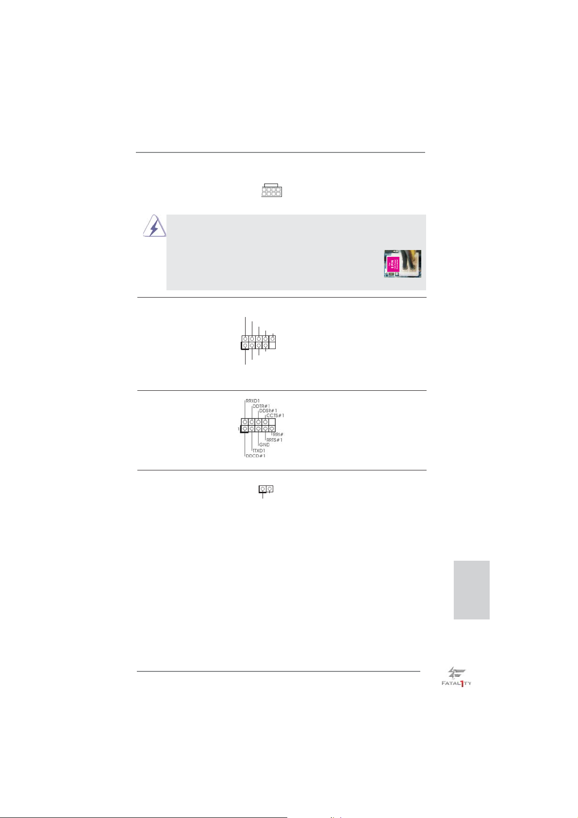
Connecteur ATX 12V Veuillez connecter une unité
(ATX12V1 br.8)
(voir p.4 No. 2)
d’alimentation électrique ATX
12V sur ce connecteur.
8 5
4 1
Bien que cette carte mère possède 8 broches connecteur d’alimentation
ATX 12V, il peut toujours travailler si vous adoptez une approche
traditionnelle à 4 broches ATX 12V alimentation.
8 5
Pour utiliser l’alimentation des 4 broches ATX,
branchez votre alimentation avec la broche 1 et
la broche 5.
4-Installation d’alimentation à 4 broches ATX 12V
4 1
Header de IEEE 1394 Sauf un port de default IEEE
(FRONT_1394 br. 9)
(voir p.4 No. 28)
1394 sur le panel I/O, il y a un
header de IEEE1394
(FRONT_1394) sur cette carte
mere. Le header de IEEE 1394
peut supporter un port de IEEE
1394.
RXTPAM_0
1
RXTPAP_0
GND
GND
RXTPBM_0
+12V
+12V
RXTPBP_0
GND
En-tête de port COM Cette en-tête de port COM est
(COM1 br.9)
(voir p.4 No. 31)
utilisée pour prendre en charge
un module de port COM.
Connecteur HDMI_SPDIF Connecteur HDMI_SPDIF,
(HDMI_SPDIF1 2-pin)
(voir p.4 No. 33)
SPDIF vers la carte VGA HDMI,
fournissant une sortie audio
1
SPDIFOUT
GND
et permettant au système de se
connecter au un téléviseur
numérique HDMI /un projecteur
/ un périphérique LCD. Veuillez
brancher le connecteur
HDMI_SPDIF de la carte VGA
HDMI sur ce connecteur.
Fatal1ty Z77 Professional Series Motherboard
Français
91
Page 92
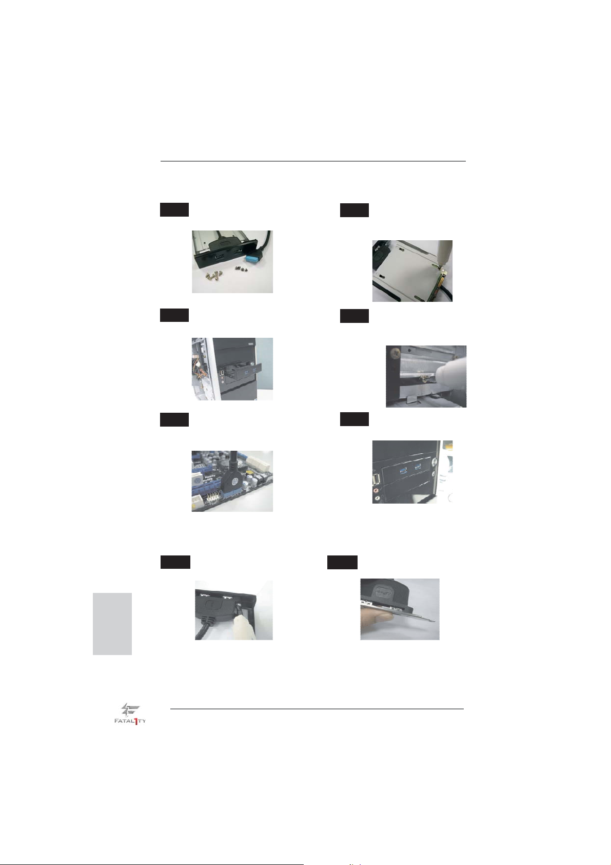
Le Guide d’installation du panneau USB 3.0 frontal
Etape 1
Préparez le panneau USB 3.0 frontal fourni,
quatre vis HDD et six vis de châssis.
Vissez le HDD/SSD 2,5” sur le
Etape 2
panneau USB 3.0. frontal avec
les quatre vis HDD.
Français
Etape 3
Installez le panneau USB 3.0 frontal dans la
baie de disque 2,5” du châssis.
Etape 5
Branchez le câble USB 3.0 dans le
connecteur USB 3.0 (USB3_6_7) de la carte
mère.
Vissez le panneau USB 3.0 frontal
Etape 4
dans la baie de disque avec les six
vis de châssis.
Etape 6
Le panneau USB 3.0 frontal peut
maintenant être utilisé.
Le Guide d'installation du Support arrière USB 3.0
Étape 1
Dévissez les deux vis du panneau
avant USB 3.0.
Étape 2
Assemblez le câble USB 3.0 et le
support arrière USB 3.0.
92
Fatal1ty Z77 Professional Series Motherboard
Page 93
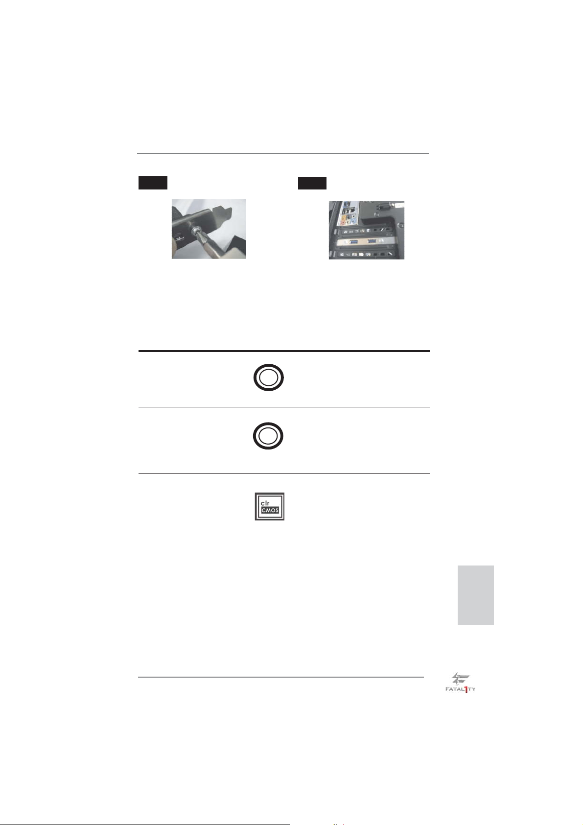
Étape 3
Vissez les deux vis dans le support
arrière USB 3.0.
Étape 4
Placez le support arrière USB 3.0
dans le châssis.
1.5 Interrupteur rapides
Cette carte mère dispose de trois interrupteurs rapides : un interrupteur d’alimentation, un interrupteur de réinitialisation et un interrupteur d’effacement de CMOS, permettant aux utilisateurs de rapidement allumer/éteindre ou réinitialiser le système,
ainsi que d’effacer les valeurs du CMOS.
Interrupteur d’alimentation
(PWRBTN)
(voir p.4 No. 16)
Interrupteur de réinitialisation
(RSTBTN)
(voir p.4 No. 17)
Interrupteur d’effacement de CMOS
(CLRCBTN)
(voir p.5 No. 18)
Power
Reset
L’interrupteur d’alimentation est
un interrupteur rapide, qui permet
à l’utilisateur d’allumer/éteindre
rapidement le système.
L’interrupteur de réinitialisation
est un interrupteur rapide, qui
permet à l’utilisateur de
réinitialiser rapidement le
système.
L’interrupteur d’effacement de
CMOS est un interrupteur rapide
qui permet à l’utilisateur d’effacer
rapidement les valeurs du CMOS.
Français
Fatal1ty Z77 Professional Series Motherboard
93
Page 94

2. Informations sur le BIOS
La puce Flash Memory sur la carte mère stocke le Setup du BIOS. Lorsque vous
démarrez l’ordinateur, veuillez presser <F2> ou <Del> pendant le POST (Power-OnSelf-Test) pour entrer dans le BIOS; sinon, le POST continue ses tests de routine. Si
vous désirez entrer dans le BIOS après le POST, veuillez redémarrer le système en
pressant <Ctl> + <Alt> + <Suppr>, ou en pressant le bouton de reset sur le boîtier
du système. Vous pouvez également redémarrer en éteignant le système et en le
rallumant. L’utilitaire d’installation du BIOS est conçu pour être convivial. C’est un
programme piloté par menu, qui vous permet de faire défi ler par ses divers sous-
menus et de choisir parmi les choix prédéterminés. Pour des informations détaillées
sur le BIOS, veuillez consulter le Guide de l’utilisateur (fi chier PDF) dans le CD
technique.
3. Informations sur le CD de support
Cette carte mère supporte divers systèmes d’exploitation Microsoft® Windows®: 7
/ 7 64 bits / VistaTM / Vista
cette carte mère contient les pilotes et les utilitaires nécessaires pour améliorer les
fonctions de la carte mère. Pour utiliser le CD technique, insérez-le dans le lecteur
de CD-ROM. Le Menu principal s’affi che automatiquement si “AUTORUN” est activé
dans votre ordinateur. Si le Menu principal n’apparaît pas automatiquement, localisez dans le CD technique le fi chier “ASSETUP.EXE” dans le dossier BIN et double-
cliquez dessus pour affi cher les menus.
TM
64 bits / XP / XP 64 bits. Le CD technique livré avec
Français
94
Fatal1ty Z77 Professional Series Motherboard
Page 95
1. Introduzione
Grazie per aver scelto una scheda madre ASRock Fatal1ty Z77 Professional
Series, una scheda madre affidabile prodotta secondo i severi criteri di qualità
ASRock. Le prestazioni eccellenti e il design robusto si conformano all’impegno di
ASRock nella ricerca della qualità e della resistenza.
Questa Guida Rapida all’Installazione contiene l’introduzione alla motherboard e la
guida passo-passo all’installazione. Informazioni più dettagliate sulla motherboard si
possono trovare nel manuale per l’utente presente nel CD di supporto.
Le specifi che della scheda madre e il software del BIOS possono essere
aggiornati, pertanto il contenuto di questo manuale può subire
variazioni senza preavviso. Nel caso in cui questo manuale sia
modifi cato, la versione aggiornata sarà disponibile sul sito di ASRock
senza altro avviso. Sul sito ASRock si possono anche trovare le più
recenti schede VGA e gli elenchi di CPU supportate.
ASRock website http://www.asrock.com
Se si necessita dell’assistenza tecnica per questa scheda madre, visitare
il nostro sito per informazioni specifi che sul modello che si sta usando.
www.asrock.com/support/index.asp
1.1 Contenuto della confezione
Scheda madre ASRock Fatal1ty Z77 Professional Series
(ATX Form Factor: 12.0-in x 9.6-in, 30.5 cm x 24.4 cm)
Guida di installazione rapida ASRock Fatal1ty Z77 Professional Series
CD di supporto ASRock Fatal1ty Z77 Professional Series
Sei cavi dati Serial ATA (SATA) (opzionali)
Due cavi di alimentazione HDD Serial ATA (SATA) (opzionali)
Un I/O Shield
Un porta USB 3.0 sul pannello frontale
Quattro HDD viti
Sei telaio viti
Un supporto USB 3.0 posteriore
Un scheda ASRock SLI_Bridge_2S
ASRock vi ricorda...
Per ottenere migliori prestazioni in Windows® 7 / 7 64-bit / Vista
64-bit, si consiglia di impostare l'opzione BIOS in Storage Confi guration
(Confi gurazione di archiviazione) sulla modalità AHCI. Per l'impostazione
BIOS, fare riferimento a “User Manual” (Manuale dell'utente) nel CD di
supporto per dettagli.
TM
/ VistaTM
Fatal1ty Z77 Professional Series Motherboard
Italiano
95
Page 96
Italiano
1.2 Specifiche
Piattaforma - ATX Form Factor: 12.0-in x 9.6-in, 30.5 cm x 24.4 cm
- Design Premium Gold Capacitor (condensatori a polimeri
conduttivi di altissima qualità 100% made in Japan)
Processore - Supporta Intel
pacchetto LGA1155
- Design Digi Power
- Struttura di fase con alimentazione 16 + 8
- Supporto della tecnologia Intel
- Supporta CPU unlocked serie K
- Supporto tecnologia Hyper Threading (vedi ATTENZIONE 1)
- Supporta tecnologia Intel® Rapid Start Technology e Smart
Connect Technology con CPU Intel® Ivy Bridge
Chipset - Intel
®
Z77
Memoria - Supporto tecnologia Dual Channel Memory
(vedi ATTENZIONE 2)
- 4 x slots DDR3 DIMM
- Supporto DDR3 2800+(OC)/2400(OC)/2133(OC)/1866(OC)/
1600/1333/1066 non-ECC, momoria senza buffer
- Capacità massima della memoria di sistema: 32GB
(vedi ATTENZIONE 3)
- Supporto di Intel
Slot di - 2 x Alloggio PCI Express 3.0 x16 (PCIE2/PCIE4: singolo in
espansione modalità x16 (PCIE2) / x8 (PCIE4) o doppio in modalità x8/x8)
(vedi ATTENZIONE 4)
* PCIE 3.0 è supportato soltanto con la CPU Intel® Ivy Bridge.
Con la CPU Intel® Sandy Bridge, supporta solamente PCIE
2.0.
- 1 x Alloggio PCI Express 2.0 x16 (PCIE5 : modalità x4)
- 2 x Alloggio PCI Express 2.0 x1
- 2 x Alloggio PCI
- Supporto di AMD Quad CrossFireX
CrossFireX
- Supporto di NVIDIA® Quad SLITM e SLI
VGA su scheda * Le uscite Intel® HD Graphics Built-in Visuals e VGA possono
essere supportate solo con processori dotati di GPU
integrata.
- Supporta Intel
Video, Intel® InTruTM 3D, Intel® Clear Video HD Technology,
Intel® HD Graphics 2500/4000, Intel® Advanced Vector
Extensions (AVX)
96
Fatal1ty Z77 Professional Series Motherboard
®
CoreTM i7 / i5 / i3 di 3a e 2a generazione in un
®
Turbo Boost 2.0
®
XMP (Extreme Memory Profi le)1.3/1.2
TM
TM
®
HD Graphics Built-in Visuals: Intel® Quick Sync
, 3-Way CrossFireXTM e
TM
Page 97
- Pixel Shader 5.0, DirectX 11 con CPU Intel® Ivy Bridge, Pixel
Shader 4.1, DirectX 10.1 con CPU Intel® Sandy Bridge
- Memoria massima condivisa 1760MB (vedi ATTENZIONE 5)
- Uscita VGA Doppia: supporto porte HDMI e DisplayPort
tramite verifi catore display indipendente
- Supporta HDMI 1.4a con risoluzione massima fi no a
1920x1200 @ 60Hz
- Supporta DisplayPort con risoluzione massima fi no a
2560x1600 @ 60Hz
- Supporto delle funzioni Auto Lip Sync, Deep Color (12bpc),
xvYCC e HBR (High Bit Rate Audio) con HDMI (è necessario
un monitor compatibile HDMI) (vedi ATTENZIONE 6)
- Supporto della funzione HDCP con le porte HDMI e
DisplayPort
- Supporto 1080p Blu-ray (BD) / HD-DVD riproduzione con le
porte HDMI e DisplayPort
Audio - 7.1 CH HD Audio con protezioni contenuti
(Realtek ALC898 Audio Codec)
- Supporto audio Blu-ray Premium
- Supporto THX TruStudio
TM
LAN - PCIE x1 Gigabit LAN 10/100/1000 Mb/s
- Broadcom BCM57781
- Supporta Wake-On-LAN
- Supporto di Energy Effi cient Ethernet 802.3az
-
Supporta Dual LAN con funzione teaming
- Supporta PXE
Pannello I/O Panel
posteriore I/O - 1 x porta PS/2 per tastiera/mouse
- 1 x Porta HDMI
- 1 x DisplayPort
- 1 x porta ottica SPDIF Out
- 5 x porte USB 2.0 già integrate
- 1 x porta Fatal1ty per Mouse (USB 2.0)
- 1 x Connettore eSATA3
- 6 x porte USB 3.0 già integrate
- 2 x porte LAN RJ-45 con LED (LED azione/collegamento e
LED velocità)
- 1 x porte IEEE 1394
- 1 x interruttore di pulizia CMOS con LED
- Connettore HD Audio: cassa posteriore / cassa centrale /
bassi / ingresso linea / cassa frontale / microfono
(vedi ATTENZIONE 7)
Fatal1ty Z77 Professional Series Motherboard
Italiano
97
Page 98
Italiano
SATA 3 - 2 x Connettori SATA3 6,0Gb/s Z77 Intel®, supporto RAID
(RAID 0, RAID 1, RAID 5, RAID 10, Intel Rapid Storage e
tecnologia Intel Smart Response) e delle funzioni NCQ, AHCI
e Hot Plug
- 4 x Connettori SATA3 6,0Gb/s ASM1061 ASMedia, supporto
delle funzioni NCQ, AHCI e Hot Plug (il connettore SATA3_A4
è condiviso con la porta eSATA3)
USB 3.0 - 2 x porte USB 3.0 posteriori amministrate dal controller
®
Intel
Z77, supporto di USB 1.0/2.0/3.0 fi no a 5Gb/s
- 4 x porte USB 3.0 posteriori amministrate dal controller
Etron EJ188H, supporto di USB 1.0/2.0/3.0 fi no a 5Gb/s
- 1 x header USB 3.0 frontale (supporta 2 porte USB 3.0)
amministrato dal controller Intel
®
Z77, supporto di
USB 1.0/2.0/3.0 fi no a 5Gb/s
Connettori - 4 x connettori SATA2 3.0Go/s, sopporta RAID (RAID 0, RAID 1,
RAID 5, RAID 10, Intel Rapid Storage e tecnologia Intel Smart
Response) e delle funzioni NCQ, AHCI e Hot Plug
- 6 x connettori SATA3 6.0Go/s
- 1 x connettori ATA133 IDE (supporta fi no a 2 dispositivi IDE)
- 1 x porta Floppy
- 1 x Collettore modulo infrarossi
- 1 x collettore porta COM
- 1 x connettore HDMI_SPDIF
- 1 x collettore IEEE 1394
- 1 x LED di accensione
- Connettore CPU/Chassis/potenza Alimentazione ventola
- 24-pin collettore alimentazione ATX
- 8-pin connettore ATX 12V
- Connettori audio interni
- Connettore audio sul pannello frontale
- 2 x Collettore USB 2.0 (supporta 4 porte USB 2.0)
- 1 x Collettore USB 3.0 (supporta 2 porte USB 3.0)
- 1 x Dr. Debug (LED debug con 7 segmenti)
Interruttore - 1 x interruttore pulizia CMOS con LED
rapido - 1 x interruttore di alimentazione con LED
- 1 x interruttore di reset con LED
BIOS - 64Mb AMI UEFI Legal BIOS con interfaccia di supporto
- Supporta “Plug and Play”
- Compatibile con ACPI 1.1 wake up events
- Supporta jumperfree
- Supporta SMBIOS 2.3.1
98
Fatal1ty Z77 Professional Series Motherboard
Page 99
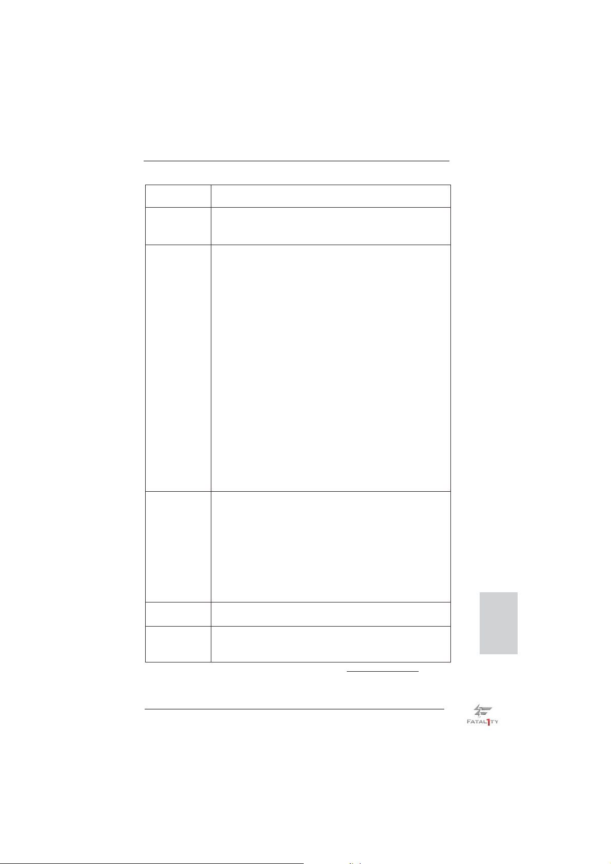
- Regolazione multi-voltaggio CPU Core, IGPU, DRAM, 1.8V
PLL, VTT, VCCSA
CD di - Driver, Utilità, Software AntiVirus (versione di prova),
supporto CyberLink MediaEspresso 6.5 Trial, Suite multimediale
ASRock MAGIX - OEM
Caratteristica - F-Stream (vedi ATTENZIONE 8)
speciale - ASRock Instant Boot
- ASRock Instant Flash (vedi ATTENZIONE 9)
- Caricatore ASRock APP Charger (vedi ATTENZIONE 10)
- ASrock SmartView (vedi ATTENZIONE 11)
- ASRock XFast USB (vedi ATTENZIONE 12)
- ASRock XFast LAN (vedi ATTENZIONE 13)
- ASRock XFast RAM (vedi ATTENZIONE 14)
- ASRock Crashless BIOS (vedi ATTENZIONE 15)
- Lucid Virtu Universal MVP (vedi ATTENZIONE 16)
* Lucid Virtu Universal MVP può essere supportato solo con
processori dotati di GPU integrata.
- Booster ibrido:
- Stepless control per frequenza del processore
(vedi ATTENZIONE 17)
- ASRock U-COP (vedi ATTENZIONE 18)
- Boot Failure Guard (B.F.G.)
- Opzione C.C.O. (Combo Cooler Option)
(vedi ATTENZIONE 19)
- LED notturno
Monitoraggio - Sensore per la temperatura del processore
Hardware - Sensore temperatura scheda madre
- Indicatore di velocità per la ventola del CPU/Chassis/potenza
Alimentazione
- Ventola CPU/Chassis silenziosa (permette la regolazione
automatica della ventola dello chassis in base alla temperatura
della CPU)
- Ventola CPU/chassis con controllo di varie velocità
- Voltaggio: +12V, +5V, +3.3V, Vcore
Compatibilità - Microsoft
®
Windows® 7 / 7 64 bit / VistaTM / Vista
TM
64 bit / XP /
SO XP 64 bit (vedi ATTENZIONE 20)
Certifi cazioni - FCC, CE, WHQL
- Predisposto ErP/EuP (è necessaria l’alimentazione
predisposta per il sistema ErP/EuP) (vedi ATTENZIONE 21)
* Per ulteriori informazioni, prego visitare il nostro sito internet: http://www.asrock.com
Italiano
Fatal1ty Z77 Professional Series Motherboard
99
Page 100

Italiano
AVVISO
Si prega di prendere atto che la procedura di overclocking implica dei rischi, come
anche la regolazione delle impostazioni del BIOS, l’applicazione della tecnologia
Untied Overclocking Technology, oppure l’uso di strumenti di overclocking forniti da
terzi. L’overclocking può infl uenzare la stabilità del sistema, ed anche provocare
danni ai componenti ed alle periferiche del sistema. La procedura è eseguita a pro
prio rischio ed a proprie spese. Noi non possiamo essere ritenuti responsabili per
possibili danni provocati dall’overclocking.
ATTENZIONE!
1. Per il settaggio della “Tecnologia Hyper-Threading”, per favore controllare
pagina 73 del Manuale dell’utente all’interno del CD di supporto.
2. Questa scheda madre supporta la tecnologia Dual Channel Memory. Prima
di implementare la tecnologia Dual Channel Memory, assicurarsi di leggere
la guida all’installazione dei moduli di memoria, a pagina 19, per seguire
un’installazione appropriata.
3. A causa delle limitazioni del sistema operativo, le dimensioni effettive della
memoria possono essere inferiori a 4GB per l’accantonamento riservato
all’uso del sistema sotto Windows
CPU 64-bit, non c’è tale limitazione. Si può usare ASRock XFast RAM per
fare uso della memoria che Windows® non può utilizzare.
4. Solo lo slot PCIE2 e PCIE4 supporta velocità fi no a Gen 3. Per utilizzare
PCI Express a velocità Gen 3, bisogna installare la CPU Ivy Bridge. Se
si installa la CPU Sandy Bridge, PCI Express opererà soltanto a velocità
Gen 2 PCI Express.
5. La dimensione massima della memoria condivisa viene stabilita dal venditore del chipset ed e‘ soggetta a modifi cazioni. Prego fare riferimento al
sito internet Intel
6. Le funzioni xvYCC e Deep Color sono supportate solo sotto Windows®
7 64-bit / 7. La modalità Deep Color sarà abilitata solo se lo schermo
supporta la funzione 12bpc in EDID. La funzione HBR è supportata sotto
Windows
7. Questa scheda madre supporta l’ingresso stereo e mono per il microfono.
Questa scheda madre supporta le modalità 2 canali, 4 canali, 6 canali e
8 canali per l’uscita audio. Controllare la tavola a pagina 5 per eseguire il
collegamento appropriato.
8.
L’utilità F-Stream è uno strumento tutto in uno per regolare varie funzioni
del sistema in un’interfaccia facile da usare che include monitoraggio
hardware, controllo ventola, overclocking, OC DNA ed IES. Hardware
Monitor (Monitoraggio hardware) mostra le letture principali del sistema.
Fan Control (Controllo ventola) mostra la velocità e la temperatura che
possono essere regolate. Overclocking permette di eseguire l’overclocking
della frequenza della CPU per ottenere le prestazioni ottimali del sistema.
OC DNA permette di salvare le impostazioni OC come un profi lo da
condividere con gli amici! Gli amici possono scaricare il profi lo OC sul
®
per le ultime informazioni.
®
7 64-bit / 7 / VistaTM 64-bit / VistaTM.
®
7 / VistaTM / XP. Per Windows® OS con
100
Fatal1ty Z77 Professional Series Motherboard
 Loading...