

FasTest XT Series Rebuild User Manual
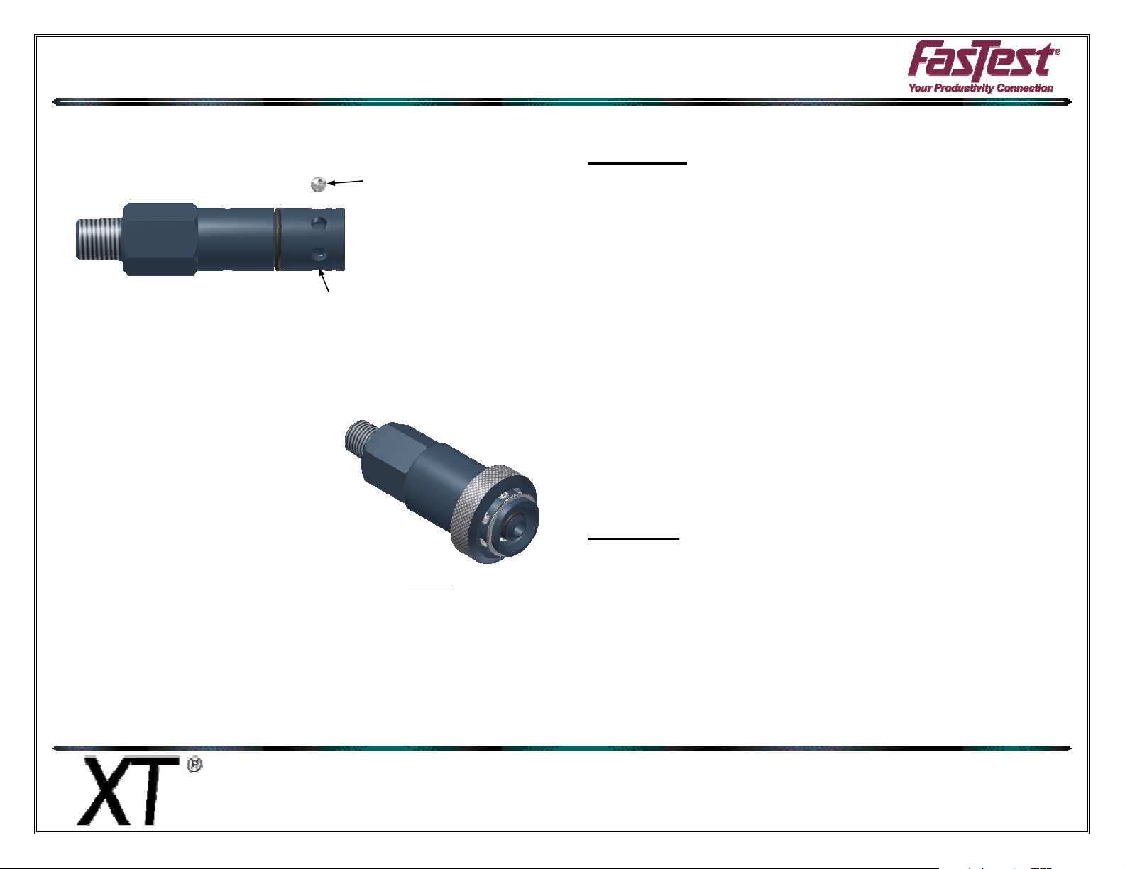
XT Connector Exploded
View
REBUILD INSTRUCTIONS
9. Place a small amount of petroleum jelly into the latching ball holes in the
body. This will help retain the balls while assembling the connector. Insert
the larger latching balls(3) into the latching ball holes in the body.
10. Lubricate the inside of sleeve(7) and slide it over the body(1) until it
bottoms. Make sure the small outside diameter of the sleeve is towards
the termination end.
11. Install the retaining ring(9) into the front groove in body.
12. Check connector operation and leak test.
13. Discard all used components.
LATCHING BALL HOLES
LATCHING BALL (3)
FasTest, Inc. Product Warranty
FasTest, Inc. warrants its products against defects of workmanship and/or material for 12 months from the date of the
sale by FasTest, Inc. This warranty is void if the product is misused, tampered with or used in a manner that is not in
accordance with FasTest, Inc. recommendations and/or instructions. FasTest, Inc. is not liable for consequential or
other damages including, but not limited to, loss, damage, personal injury, or any other expense directly or indirectly
arising from the use of or inability to use its products either separately or in combination with other products. ALL
OTHER WARRANTIES EXPRESSED OR IMPLIED, WHETHER ORAL OR WRITTEN, INCLUDING BUT NOT
LIMITED TO WARRANTIES OR MERCHANTABILITY OR FITNESS FOR A PARTICULAR PURPOSE ARE
EXPRESSLY EXCLUDED.
Remedy under this warranty is limited to replacement of the product or an account credit in the amount of the original
selling price, at the option on FasTest, Inc. All allegedly defective products must be returned prepaid transportation to
FasTest, Inc. along with information describing the products performance, unless disposition in the field is authorized
in writing by FasTest, Inc.
XTR Rebuild Instructions
Description:
Please thoroughly read the instructions prior to
rebuilding the XT Connector. If you do not understand
instructions, or if components are missing, call FasTest
before rebuilding connector.
Disassembly:
1. Open the rebuild kit and remove instructions from bag. Slide the
sleeve(7) back toward the termination end to expose the retaining ring(9).
Using a pick (or like tool), remove the retaining ring. Note: the retaining
ring will be replaced.
2. Slide the sleeve(7) off the end of the connector opposite the termination
end.
3. The latching balls(3) can now be removed. They will either fall out or can
be pushed from the inside. Note: the balls will be replaced.
XT Connector rebuild instructions
Roseville, MN
Ph: 1-800-444-2373
Fax: 651-645-7390
www.fastestinc.com
WP070 10/6/2010
REBUILD INSTRUCTIONS
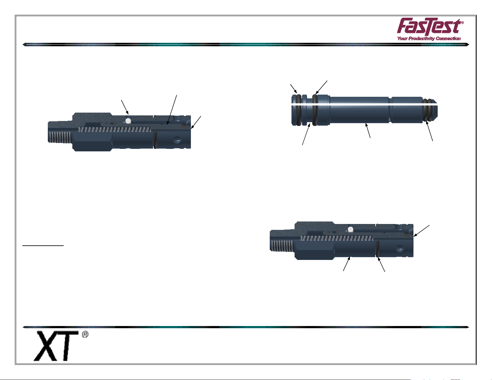
4. Depress the piston(6) flush with body(1), then use compressed air and
blow air into the smaller retaining ball hole in the body(1). The retaining
balls(2) should be forced out the other, larger ball hole in the body. If they
do not come out, the connector may need to be cleaned, so the balls
move freely. Note: the balls will be replaced.
SMALL RETAINING
BALL HOLE
PISTON (6)
FLUSH
5. The piston(6) should now be free. Simply pull and remove the piston(6).
The internal spring(4) will be loose and can be removed.
6. Remove o-rings(5, 10 & 11) from the piston. Note: the o-rings will be
replaced.
7. Remove the o-ring(8) from the outside of the body. Note: the o-ring will be
replaced.
Re-Assembly:
1. Make sure all components have been cleaned and are ready for
assembly. Open the rebuild kit and identify the components.
2. Install the smallest o-rings(11) onto the piston(6).
3. Install the Teflon coated o-ring(5) into the large wider groove in the
piston(6). Make sure the o-ring is located towards the front end of the
piston. (As shown below).
4. Install o-ring(10) into the large narrower groove on piston.
5. Lubricate the two o-rings(5 & 10) on the large end of the piston(6) with
White Petroleum Jelly. Apply lubricate so as to fill the void between the orings. (As shown below). Note: Do not lubricate the small o-rings(11).
O-RING (10)
TEFLON O-RING (5) TO THIS SIDE OF GROOVE
FILL THIS AREA WITH LUBE
PISTON (6)
DO NOT LUBE THESE
TWO O-RINGS
6. Place the spring(4) into the piston(6) and install the assembly into the
body(1).
7. Compress the piston(6) into the body(1) until it stops. Install the small
balls(2) through the larger retaining ball hole in the body(1).
COMPRESS
PISTON
LARGE RETAINING
BALL HOLE
O-RING (8)
8. Install the sleeve friction o-ring(8) into groove on outside of the body(1).
Roseville, MN
Ph: 1-800-444-2373
Fax: 651-645-7390
www.fastestinc.com
WP070 10/6/2010
 Loading...