


FE01
SPANNER
CCW
FE SEAL SET
SEE CHART 1
ASSEMBLY
DIRECTION
OF SEALS
& WASHERS
SEAL
CASING
CW
SEAL CASING
DIAGRAM 2
OPERATING INSTRUCTIONS
Installation of Seals:
• For seal install or replacement
loosen set screw on side of housing.
SET SCREW
• Unscrew (counterclockwise) and
remove seal casing. NOTE: A spanner
wrench hole is provided for breaking
the seal casing loose if required.
WRENCH
HOLE
• Seal sets contain elastomer seals and backup washers per Chart 1. For complete
listing of seal set size ranges see catalog.
• Verify that seals and washers are the same size.
• Assemble seal set into seal casing.
See Chart 1.
• Reassemble and tighten seal casing w/seal set to housing.
• Retighten set screw.
*Seal Set Parts Required CHART 1
Connector Number of Seals Number of Washers
FE01, FE01M 1 2
FE1, FE1M 1 2
FE2, FE2M 2 2
FE3, FE4, FE3M, FE4M 3 2
FE5, FE6, FE5M, FE6M 3 2
• Use of less than the listed number of seals (for less insertion depth) requires a spacer. See FasT-
est catalog. Seal Installation Instructions included with seal sets.
• WARNING: Seals and washers must have the same size outside and inside diameters. Use of the
incorrect size seals or washers will result in loss of seal ability.
WITH SEAL SET
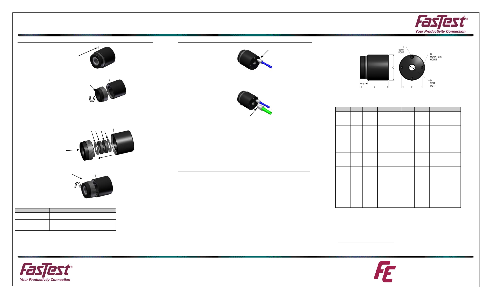
Attachment of Pilot Pressure and Test Media Supply Line:
FE MODEL CONNECTOR
• Attach pilot pressure line
to pilot port “E” from Diagram 2.
• A pneumatic regulated source is required to maximize seal life and assure optimum
seal ability for the application. The pilot pressure should be minimized to maintain
sealing on the test piece without excessive compression of the seal.
• Attach test media line to
test port “D” from Diagram 2.
FITTING/TUBING
TO TEST PORT “D”
• Provide a means whererby test pressure will not be introduced until the pilot pressure required to seal is reached. The means should also provide quick exhaust of
test pressure in the event pilot pressure falls below the minimum required to seal.
Mounting of Connector:
The FE Connector must be SECURED to the test piece by a mechanical device
before proceeding.
• The test connector must be secured with a mechanical or other device to assure the
connector is not uncoupled from the test piece. The test itself will provide an uncoupling force. The securing or holding device may be a fixture, clamp, cylinder or
other appropriate means that prevents ejection of the test piece from the connector.
Uncoupling force example:
If the test piece has a ½” O.D. and is tested at 400 psi maximum. The uncoupling force = area(πr²) x
pressure) = π x .25² x 400 = 79 lbs.
• Secured device should be designed to withstand this force and include an adequate margin for
safety.
• Do not activate the connector without an adequate and safe securing mechanism.
• Mount the FasTest FE connector to the fixture or appropriate device using either threaded
mounting holes on the rear of the connector body, (“G” Diagram 2), or appropriate adapter.
FITTING/TUBING
TO PILOT PORT “E”
FE Connector Dimensions
Maximum test pressure: Vacuum to 500 psi
Flow capability: Limited by “D” below
CHART 2
FE A C D E F G* L**
FE01
FE01M
FE1
FE1M
FE2
FE2M
FE3
FE3M
FE4
FE4M
FE5
FE5M
FE6
FE6M
* FE4, FE4M, FE5, FE5M, FE6, FE6M have 3 mounting holes.
**L = Minimum insertion length of test piece.
Material Specifications
Body, Housing, Piston: Aluminum
Main Seal Washers: Steel QPQ treated or Stainless Steel
Main Seal: Neoprene
O-rings: Buna-N
Other materials available on request.
NOTE: All specifications subject to change without notice.
2.05 1.49 1/8
2.72 2.22 ¼
3.50 3.11 ½
4.48 4.23 1 NPTF
4.60 5.48 1-1/2
4.60 6.98 2 NPTF
4.97 7.48 2-1/2
NPTF
1/8
BSPP
NPTF
¼
BSPP
NPTF
½
BSPP
1 BSPP
NPTF
1-1/2
BSPP
2 BSPP
NPTF
2-1/2
BSPP
10-32
UNF
M5x.8
1/8
NPTF
1/8
BSPP
1/8
NPTF
1/8
BSPP
1/8
NPTF
1/8
BSPP
1/8
NPTF
1/8
BSPP
1/8
NPTF
1/8
BSPP
1/8
NPTF
1/8
BSPP
1.10 10-32
1.62 ¼-28
2.50 ¼-28
3.25 ¼-28
4.25 ¼-28
5.50 3/8-24
6.12 3/8-24
UNF
M5x.8
UNF
M6x1
UNF
M6x1
UNF
M6x1
UNF
M6x1
UNF
M11x1.5
UNF
M11x1.5
.58
1.06
1.06
1.64
1.64
1.64
1.64
www.fastestinc.com
Roseville, MN
Ph 1-800-444-2373
Fax 651-645-7390
WP007 03/2009
 Loading...