

FasTest JNL User Manual
JNL
0H Series
DIAMETER .11”
JNL1
Series
DIAMETER .17”
SEAL
O-RING
(H) WASHER
LOC
ATION
ASSEMBLY
OPERATING INSTRUCTIONS
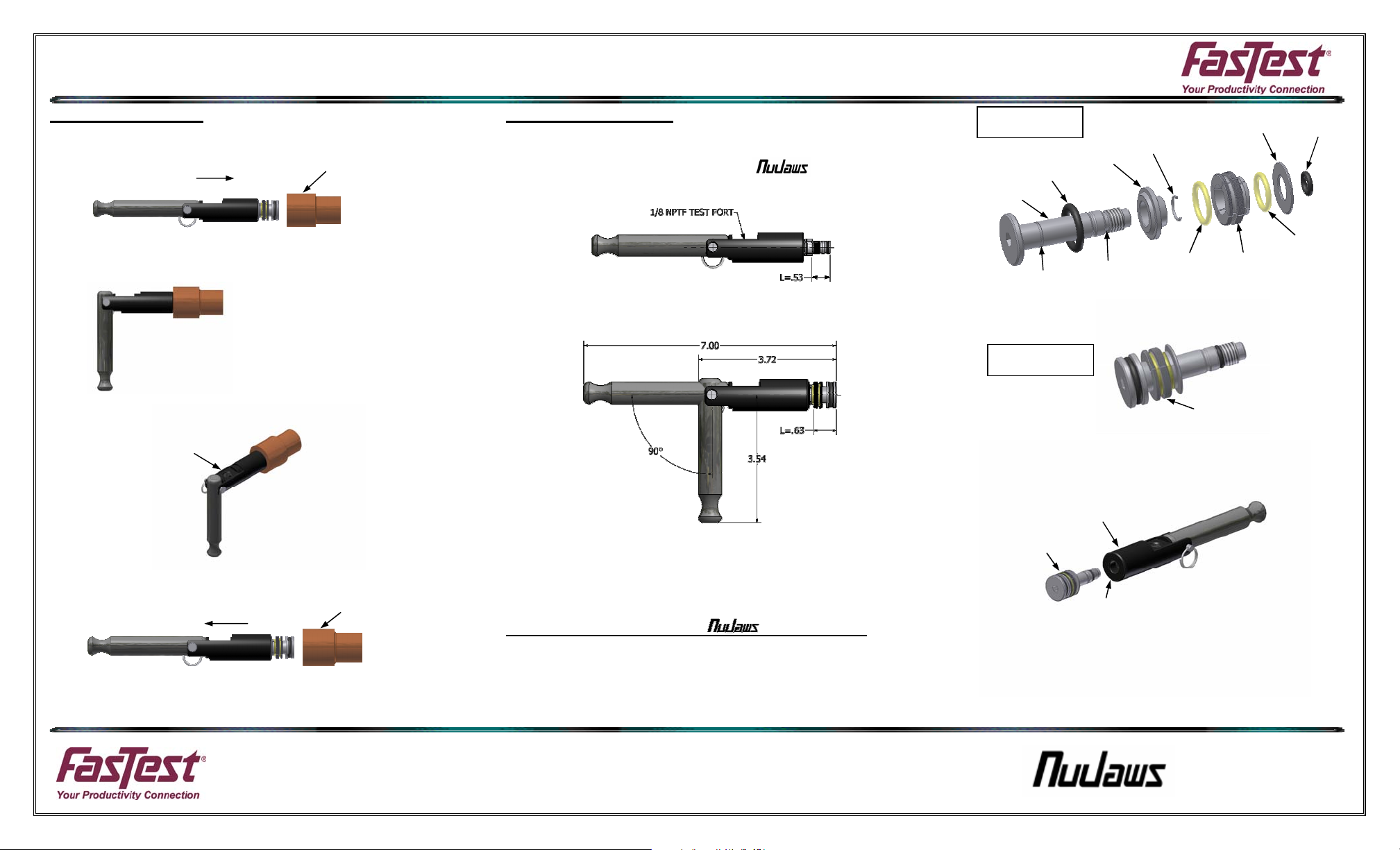
Operating Instructions:
CONNECTING ACTION:
1. Insert connector into test piece. Make sure test piece is inserted to the required
minimum insertion length. This will assure proper location relative to the seals.
2. Rotate lever to the 90 degree position for grip and seal action. After connecting,
always tug on the connector to assure proper engagement and gripping of the collet
before introduction of pressurized test media.
Note: Lever is designed to rotate down when connector test port is on top.
3. Introduce test media through test port.
DISCONNECTING ACTION:
1. Vent test media pressure.
2. Rotate lever to in-line position.
3. Remove connector.
Note: Connector should be pulled straight back. If connector catches, push forward
and pull back. Do not attempt to force out a connector that is catching. This will
cause it to jam in the test piece port.
GRIP & SEAL POSITION
TEST MEDIA PORT
INSERT CONNECTOR
REMOVE CONNECTOR
TEST PIECE
TEST PIECE
WP011 04/2009
Dimensional Information:
All DIMENSIONS APPLY TO BOTH SIZES EXCEPT “L” (Minimum insertion length of test
piece for standard application).
Lever in-line for connector insertion and disconnect
Lever at 90 degree position to grip and seal
Collet and Seal Installation for JNL Connector:
ASSEMBLY OF COLLET AND SEAL SET:
1. Set connector shaft (A) on table so that the threaded end is pointed upward. Place
main seal (B) onto shaft as shown.
2. Install sleeve ramp (C) onto shaft so that smooth flat area is against main seal.
3. Place small C-Ring (D) into groove shown. Most easily installed from side. Sleeve
ramp may need to be squeezed close to flat end of shaft to expose c-ring groove.
LEVER ACTION
MAX. FLOW
MAX. FLOW
EXPLODED VIEW OF
COLLET SET
(C) SLEEVE
(B) MAIN
(A) SHAFT
C-RING
LOCATION
4. Assemble the collet segments (F) and retaining o-ring(s) (E) & (G). Arrange the four
pieces of collet (F) into a circle with the raised area facing upward. Place the
retaining o-ring(s) into the groove(s) on the raised area.
ASSEMBLY VIEW OF
COLLET SET
5. Install complete collet and retaining o-ring assembly onto shaft (A) as shown in
diagram. Note that the I.D. of the collet assembly is tapered. Larger end of this
tapered I.D. goes on the shaft (A) first.
6. Place washer (H) on shaft (A).
7. Place shaft o-ring (I) onto shaft (A) and into groove immediately in front of thread.
8. The shaft assembly is now ready to attach to the connector body. Apply a drop of
Loctite® to the threads to avoid loosening during use.
COLLET &
SEAL SET
RAMP
SHAFT
O-RING
(J) BODY
9. Holding body (J) with shaft hole pointed downward, insert threaded end of shaft (A)
into hole in body (J). A hex hole at front of shaft is provided to tighten shaft into body
until snug. Collet set should be threaded in so that edge of collet (F) overlaps edge
of sleeve ramp (C) by approximately .02”.
10. Rotate the lever to actuate connector. Visually verify that the connector is gripping
and sealing action is correct before introduction of pressurized test media.
CAUTION: Keep fingers away from collet assembly. Pinching can occur.
THREAD INTO SHAFT HOLE IN BODY
(D) C-RING
(E) LARGE
RETAINING
ASSEMBLY
TAPERED END FIRST
www.fastestinc.com
® Roseville, MN
Ph 1-800-444-2373
Fax 651-645-7390
(F) COLLET
SEGMENTS
QTY. (4)
COLLET
(I) SHAFT
O-RING
(G) SMALL
RETAINING
O-RING
(LARGE
COLLET
SIZES ONLY)
OPERATING INSTRUCTIONS
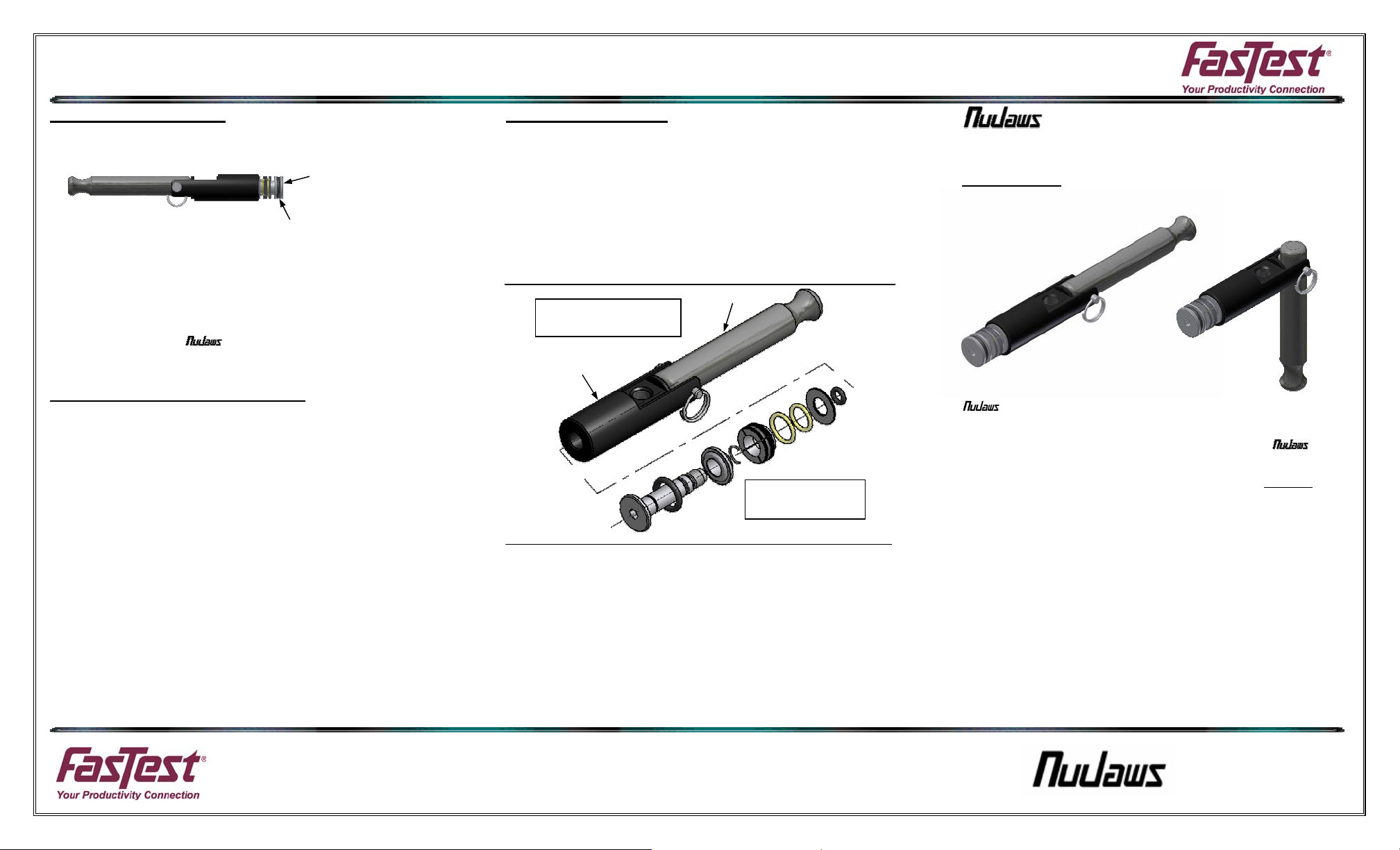
Replacement of Main Seal:
1. Place lever in the in-line position so that seal/collet assembly is in the relaxed
position. Using a pointed repair tool to get behind the main seal (B) and roll this seal
over the front of shaft.
FRONT END OF SHAFT
2. Verify correct size and material of replacement main seal.
3. Install the replacement main seal (B) by rolling it over the front end of shaft into the
space between the shaft and sleeve ramp (C). Be sure seal is seated in groove.
4. Lube collet assembly with a liquid or spray that is compatible with the main seal
material and your specific application.
5. Rotate lever to actuate connector. Visually verify that the connector gripping and
sealing action is correct.
CAUTION: Attach assembled connector to a test piece and tug on the
connector to assure proper engagement and gripping of collet before introduction
of pressurized test media.
ROLL MAIN SEAL OVER
FRONT END OF SHAFT
Safety Warnings – General Guidelines:
1. If instructions are not completely understood by operator or components
are missing, contact FasTest before attempting use of the connector.
2. All operating parameters should be considered when connector selection
is made. Parameters include, but are not limited to: dimensional
tolerance, hardness and surface finish of test piece, pressure or vacuum
requirements of application, fluid compatibility, temperature, environment
and mechanical load or vibration affecting the connector.
3. FasTest JNL Connectors must only be used with test pieces of a specific
size as indicated by the part number. Improper use could cause
separation of the connector from the test piece resulting in physical harm
or damage. The connector part number and maximum pressure rating is
marked clearly on the label.
4. FasTest JNL Connectors are to be used only on materials that meet the
following specifications: The test piece has to have a surface finish
greater than 16rms and a hardness of no more than 95Rb, to grip and
seal at the rated pressure. A surface finish of 8rms may be acceptable if
the test piece has a hardness greater than 40Rb. If the application is out
of this range, or there is a question concerning this requirement, contact
FasTest.
5. CAUTION REMINDER: Keep fingers or other objects away from
gripping collets when actuating connector. Pinching or crushing
can occur.
6. FasTest JNL Connectors are not internally valved, and will not
prevent loss of media when disconnected. Do not attempt to
disconnect unless safe conditions are met.
WP011 04/2009
Connector Maintenance:
• A daily, weekly and periodic inspection of the connector by competent person is
recommended. User must establish a regular interval for maintenance as determined
by the user media and operational environment.
• Lubricate connector on regular intervals. Petroleum jelly is recommended but care
should be taken to verify the lubricant is compatible with the application.
• Inspection should include visual checks of the collet sealing area, housing, missing
or loose components, leak tightness, ease of operation, sufficient lubrication, wear, dirt
accumulation and damage.
• Use only original FasTest spare parts that are designed for the application and are
subject to strict quality control. See warranty.
“JNL” EXPLODED VIEW
FOR REFERENCE
BODY
LEVER
EXPLODED VIEW
OF COLLET SET
FasTest, Inc. Product Warranty
FasTest, Inc. warrants its products against defects of workmanship and/or material for 12 months from the
date of the sale by FasTest, Inc. This warranty is void if the product is misused, tampered with or used in a
manner that is not in accordance with FasTest, Inc. recommendations and/or instructions. FasTest, Inc. is not
liable for consequential or other damages including, but not limited to, loss, damage, personal injury, or any
other expense directly or indirectly arising from the use of or inability to use its products either separately or in
combination with other products. ALL OTHER WARRANTIES EXPRESSED OR IMPLIED, WHETHER ORAL
OR WRITTEN, INCLUDING BUT NOT LIMITED TO WARRANTIES OR MERCHANTABILITY OR FITNESS
FOR A PARTICULAR PURPOSE ARE EXPRESSLY EXCLUDED.
Remedy under this warranty is limited to replacement of the product or an account credit in the amount of the
original selling price, at the option on FasTest, Inc. All allegedly defective products must be returned prepaid
transportation to FasTest, Inc. along with information describing the products performance, unless disposition
in the field is authorized in writing by FasTest, Inc.
JNL Lever Action Grip and
Seal Connectors.
DESCRIPTION: JNL Series Connectors seal on the inside
diameter of holes and tubes. Instant internal connections to
1,000 psi.
CONNECT/
DISCONNECT
JNL Connectors provide a reliable leak-tight connection that grips and
seals in holes and ports. Simply place the JNL connector into a port, activate
the mechanical gripping and sealing action, then introduce the test media. For
vacuum to 1000 psi applications with air, gas or liquid, Fastest JNL
Connectors provide secure, leak tight sealing for manual connections.
Please thoroughly read and understand each of the following four steps before
operating the connector. The use of pressurized media for sealing, testing and
filling requires a thorough understanding of the FasTest JNL Installation and
Operating Instructions.
1. Operating Instructions
2. Dimensional Information
3. Collet and Seal Installations
4. Safety-General Guidelines
• The connector is designed to mate with a specific application. Verify the
application prior to the introduction of pressure or processing.
• Use only in a safe environment.
• Connectors are NOT designed for permanent connections and are for
temporary connections only.
• Maximum rated test pressure for standard JNL models is 1000 psi. DO NOT
EXCEED pressure rating as marked on connector or corresponding
literature. Consult your FasTest representative with other requirements.
GRIP & SEAL
www.fastestinc.com
® Roseville, MN
Ph 1-800-444-2373
Fax 651-645-7390
 Loading...