

FasTest HPB User Manual
REPAIR KIT INSTRUCTIONS
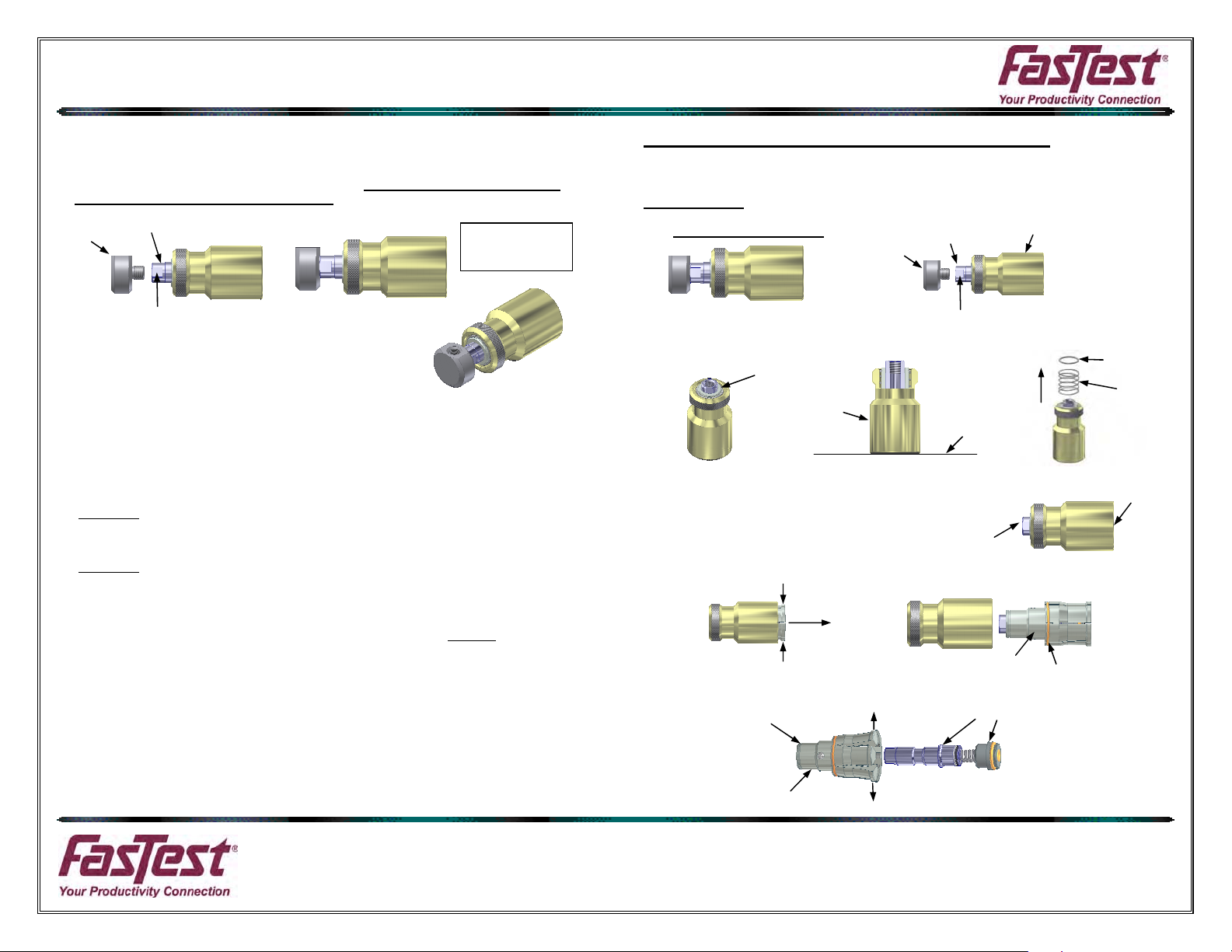
. Re-install Handle Knob. Clamp knob in vise and apply a drop of LocTite 569 onto threads of
9
knob.
10. Thread the Handle Knob into the shaft of connector. Tighten using a 13mm Open End
Wrench. Knob should be tightened to 18 ft-lbs.
Knob
Shaft
Assembled
Connector
Wrench Flats
• CAUTION: The maximum rated pressure is stamped on the connector
body. Before using, verify that this pressure rating is within your working
pressures.
• WARNING: Connect test piece and tug on the connector to assure proper
engagement and gripping before introduction of pressurized media.
• DO NOT force connector onto test part when connecting. The split collet
design should easily mate with test piece. Forcing the connector will result
in poor sealing and possible leakage.
• DO NOT turn or rotate connector after the collets have gripped the test
piece. Damage to test piece and the connector’s internal parts may result.
FasTest, Inc. Product Warranty
FasTest, Inc. warrants its products against defects of workmanship and/or material for 12 months from the date of the
sale by FasTest, Inc. This warranty is void if the product is misused, tampered with or used in a manner that is not in
accordance with FasTest, Inc. recommendations and/or instructions. FasTest, Inc. is not liable for consequential or
other damages including, but not limited to, loss, damage, personal injury, or any other expense directly or indirectly
arising from the use of or inability to use its products either separately or in combination with other products. ALL
OTHER WARRANTIES EXPRESSED OR IMPLIED, WHETHER ORAL OR WRITTEN, INCLUDING BUT NOT
LIMITED TO WARRANTIES OR MERCHANTABILITY OR FITNESS FOR A PARTICULAR PURPOSE ARE
EXPRESSLY EXCLUDED.
Remedy under this warranty is limited to replacement of the product or an account credit in the amount of the original
selling price, at the option on FasTest, Inc. All allegedly defective products must be returned prepaid transportation to
FasTest, Inc. along with information describing the products performance, unless disposition in the field is authorized
in writing by FasTest, Inc.
HPB C
onnector Repair/Rebuild Kit
“**” Denotes items included in the kit.
Disassembly:
1. Remove Handle Knob from Connector. Place knob in vise and loosen shaft from knob using
a 13mm Open End Wrench.
Knob
2. Place connector on flat surface and remove ret. ring (A) using small screwdriver/sharp tool.
3. Save spring (B), discard ret. ring (A).
** Ret. Ring (A)
Shaft
Wrench Flats
Sleeve
Table
Surface
Sleeve
** Ret. Ring (A)
Spring (B)
4. After (A) & (B) are removed, slide connector to edge of table. Make sure collets remain
inside sleeve and flush with end of sleeve.
5. Push on shaft with left thumb and squeeze collets as they
expose themselves from sleeve with right hand.
6. Continue to squeeze collets as you pull the
entire assembly from sleeve.
7. After (ZZ) Assy is removed from sleeve grab body with either hand allowing collets to open.
ull Shaft & Piston Assy from collets.
P
Squeeze
Squeeze
Ret. Ring Groove
Body
Pull
Collets Opened
Collets Opened
Shaft
Body
Shaft & Piston
Assy.
Shaft,Collet,Body,
Piston Assy. (ZZ)
** Collet O-Ring (C)
Roseville, MN
Ph: 1-800-444-2373
Fax: 651-645-7390
www.fastestinc.com
WP102 RevB 11/16/2012
Collets Flush
with Sleeve
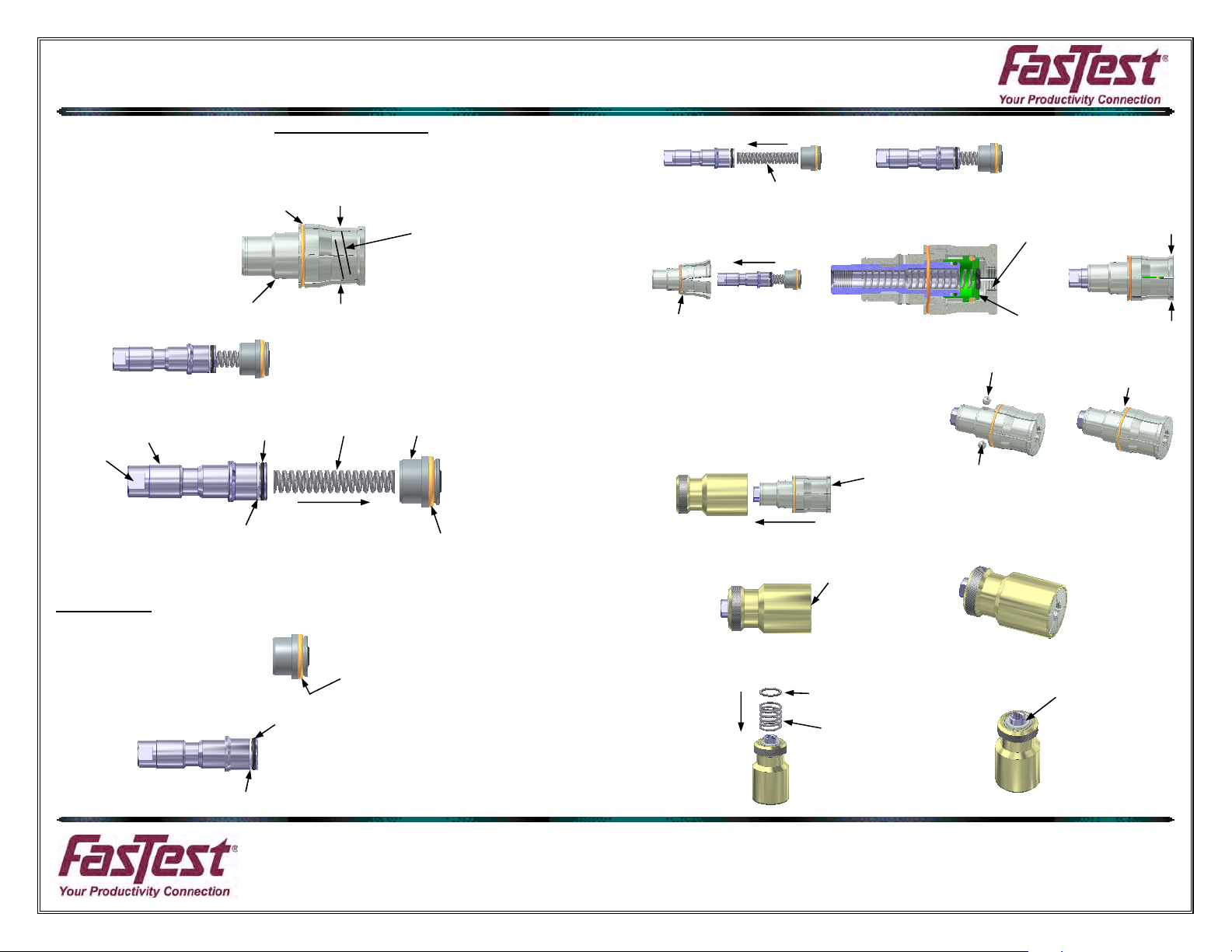
REPAIR KIT INSTRUCTIONS
8. Collet O-Ring or Garter Spring(C) removal and replacement. Squeeze tightly around col-
lets with either hand. Using a repair pick, or similar tool remove o-ring (C). Replace with new
o-ring (C) to keep collets together on body.
Note: Collets are a matched set. If collet(s) fall off body they must be assembled
correctly. There is a spiral groove on the outside of collets that must be aligned as they
are assembled.
** Collet O-Ring (C)
Squeeze
Spiral
Groove
9. Spring force will push piston off of shaft. This will expose (D) & (F) on shaft.
Body
Squeeze
10. Remove and discard the following items: (D), (E), (F) & (G). Use a sharp tool to remove
o
-rings.
Wrench
Flats
Shaft
** Shaft O-Ring
(D)
** Piston Spring
(E)
Piston
** Back-Up Ring
(F)
** Piston Outer O-Ring
(G)
Reassemble:
Use all the new seals provided and lubricate lightly with silicone.
1. Install new piston outer o-ring (G).
2. Install the following two new items onto shaft (D) & (F).
** Shaft O-Ring (D)
** Back-Up Ring
(F)
** Piston Outer O-Ring
(G)
3. Install new piston spring (E) into shaft. Then place piston onto spring as shown.
** Piston Spring
(E)
4. Using an arbor press or best set-up push shaft assembly into jaw/body assembly until piston
face is in past jaw threads. Squeeze collets with hand.
Jaw Threads
Jaw/Body Assy
Piston Face
5
. Maintain squeeze on collets and make sure balls are in holes on body.
Assembly (ZZ) is now ready to be inserted into sleeve.
6. Maintain squeeze on collets and
insert assembly (ZZ) into sleeve.
Collet Face
7. Insert assembly (ZZ) until collet faces are flush with end of sleeve.
8. Place connector on a flat surface and install spring (B) and new ret. ring (A).
Collets Flush
with Sleeve
** Ret. Ring (A)
Spring (B)
** Ret. Ring (A)
Roseville, MN
Ph: 1-800-444-2373
Fax: 651-645-7390
www.fastestinc.com
WP102 RevB 11/16/2012
Shaft,Collet,Body,
Piston Assy. (ZZ)
Squeeze
Squeeze
 Loading...