

Page 1

1
FAST™ XIM™
Thank you for choosing FAST™ products; we are proud to be your manufacturer of choice. Please
read this instruction sheet carefully before beginning installation, and also take a moment to review the
included limited warranty information.
XIM™ Unit Installation
The XIM™ unit itself is designed to withstand under hood temperatures but needs to be mounted in a
location that allows for some airflow in and around the heat sink. Also keep in mind that the XIM™ is
not 100% waterproof and should not be mounted where it will be exposed to direct spray. It is also
good practice to mount the XIM™ with the connectors facing down. Typical installation locations
would be on the firewall or inside the vehicle cockpit.
Wiring
These wiring installation instructions are specific to the wiring harnesses manufactured by FAST™
only. If you are using a wiring harness other than the ones offered by FAST™, please contact your
dealer for instructions for that harness.
FAST™ wiring harnesses are labeled on each of the connectors to simplify installation. Your
application may not require the use of all the connectors in the harness. And not all harnesses will
include every connection listed below. You may also require additional accessories such as relays,
sensors and other specialized connectors to complete your installation. All of these are available for
purchase from FAST™.
Crank:
This connector simply plugs into your crank pickup. Depending upon your application, it may be
found near the harmonic balancer or towards the back of the engine near the flywheel. The crank
sensor is used by the XIM™ to determine crank speed and position.
Cam:
This connector plugs into the cam pickup. Depending upon your application, it may be found on the
end of one of the cylinder heads or the front of the intake manifold area. The cam sensor is used by the
XIM™ to find the start of the firing order.
CAM HALL EFFECT:
This connector plugs into the CAM HALL EFFECT connector on your FAST™ XFI™ Main Harness.
This connection feeds cam and crank signals from the XIM™ to the XFI™. The XIM™ crank and cam
outputs are always wired to the XFI™ discrete crank and discrete cam inputs regardless of what type
of pickups (inductive or discrete) are connected to the XIM™.
INSTRUCTIONS
FAST™
3400 Democrat Rd.
Memphis, TN 38118
Phone: (901) 260-3278 Fax: (901) 375-3408
www.fuelairspark.com
Part #FAST4-101
Revised 7/9/07
Page 2

2
CAN LINK:
This connects to the CAN LINK connection on your FAST™ XFI™ Main Harness. Both the XIM™
and the XFI™ Harness will have a pair of CAN connectors. The plug from one harness will connect to
the receptacle from the other harness. It does not matter which pair of connectors is used as long as one
pair is mated. This connection can be made through an Interconnect Cable(s) for additional reach.
There will be one loose plug and one loose receptacle at either end of the CAN wiring. These loose
ends need to be capped off with a Terminating Plug at one end and a Terminating Receptacle at the
other. This is absolutely necessary for proper network performance. The XFI™ uses the CAN Link to
tell the XIM™ what timing values are called for in the tuning file.
Warning: Before starting your engine, make sure that with the ignition switch on, the “Status” light on
the XIM™ is illuminated. This indicates that the XIM™ and XFI™ are communicating properly via
the CAN network.
Running the engine without proper CAN communication can result in permanent damage to the
XIM™ and ignition coils. If the “Status” light is not illuminated, check the following items:
• Verify that the CAN wiring is connected per the provided instructions. One male or female
connector from the XFI™ should be connected to a mating connector on the XIM™. The
unused male and female connector must have the terminating resistors plugged into them.
• Verify that the CAN retro-fit kit wires are plugged into the Blue XFI™ main connector as
follows: Green wire to pin C26 and the Yellow wire to pin C25.
• Verify that in the C-Com® software for the XFI™, under “Operational Parameters”, IPU
Ignition is selected.
• Verify that under “System Configuration”, CAN Stream is enabled.
• Verify that the XIM™ wire labeled 12V is connected to a 12V source that has power when the
switch is in the run position and during cranking.
• If after checking all of these items, you still cannot get a status light on the XIM™, call the
FAST™ EFI HELP™ line at 1-877-334-8355 for assistance before starting your engine.
CALPORT:
This connector does not connect to anything during normal operation of the XIM™ unit. It is only used
when ‘flashing’ your XIM™ unit when there is an update available. See ‘Flashing your XIM™’.
FLASH:
This is a loose wire that does not connect to anything during normal operation of the XIM™ unit. It is
only used when ‘flashing’ your XIM™ unit when there is an update available. See ‘Flashing your
XIM™’.
+12V SW:
This wire needs to be connected to a ‘switched’ power source, or in other words, a power source that is
hot whenever the engine is cranking or running. This is the wire the turns the XIM™ on and off.
+BAT:
This wire needs to go directly to your positive post of your vehicle’s battery.
-BAT/-BAT(AGND)/-BAT(DGND)/-BAT(PGND):
Any of these that are present in the harness go to the negative post of your vehicle’s battery.
FAST™
3400 Democrat Rd.
Memphis, TN 38118
Phone: (901) 260-3278 Fax: (901) 375-3408
www.fuelairspark.com
Part #FAST4-101
Revised 7/9/07
Page 3
3
BLOCK GND:
This wire is to be connected to a good paint and rust free ground source on the engine block of your
vehicle. It is only used for the LS1/LS2/LS6/LS7 engines and will not be found in other harnesses.
DRIVER COILS:
This connector plugs into the GM factory coil harness plug on the driver side valve cover. It is only
found in the LS1/LS2/LS6/LS7 engine harness.
PASSENGER COILS:
This connector plugs into the GM factory coil harness plug on the passenger side valve cover. It is only
found in the LS1/LS2/LS6/LS7 engine harness.
COILS:
This connector plugs into the FAST™ coil harness that comes with your XIM™ unit for the Mopar
Hemi applications. One coil harness is used with a 5.7L engine and another is used with a 6.1L engine.
All coil connectors are clearly labeled with cylinder numbers.
CRANK JUMPER:
This jumper connects to the CRANK connector on your FAST™ XFI™ Main Harness. It loops
together the unused wires of the ECU’s inductive crank input.
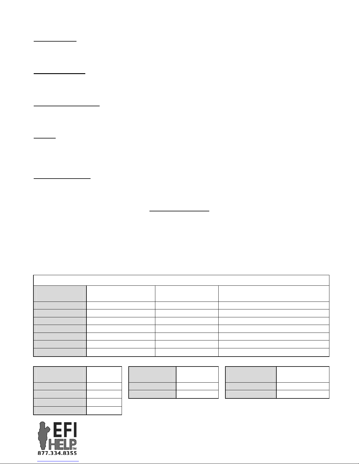
DIP Switch Settings
Your XIM™ unit is configurable for different engine applications. This is accomplished by using 8
DIP switches found inside the back cover of your unit. To access the DIP switches, simply take the lid
off by removing the 5 screws, being careful not to tear the gasket beneath the lid. Below you’ll find a
handy list of the current engine applications covered with your XIM™ unit and the switch settings that
are required for each. The “on” position is marked on the switches.
DIP Switch (1-4)
[0=OFF, 1=ON]
0 - 0 - 0 - 0 Crank Trigger 1/2/3/4X, 50* BTDC 50
1 - 0 - 0 - 0 OE Crank Trigger 1/2/3/4X, 1-10* BTDC Actual Crank Position (1-10) + 45
1 - 0 - 1 - 1 Ford Mod, 2 or 4 Valve 36-1 (1 tooth cam) 60
1 - 1 - 0 - 1 Ford Mod, 3 Valve 36-1 (5 tooth cam) 60
1 - 1 - 1 - 1 Chrysler Hemi 36-2-2 50
0 - 0 - 1 - 1 GM Gen 3 - LS1/LS6 24X (Special) 50
0 - 1 - 1 - 1 GM Gen 4 – LS2/LS7 60-2 49
DIP Switch (5-6)
[0=OFF, 1=ON]
0 - 0 2 Cylinder 1 Stand Alone 1 Coil per Cylinder
1 - 0 4 Cylinder 0 CAN Enabled 0 Waste Spark
0 - 1 6 Cylinder
1 - 1 8 Cylinder
Ignition Strategy Crank Input
# of
Cylinders
XIM™ DIP Switches
“Crank Ref. Angle (*BTDC)” setting
DIP Switch (7)
[0=OFF, 1=ON]
“CAN Enabled” allows XIM™ to
communicate with XFI™
3400 Democrat Rd.
Memphis, TN 38118
Phone: (901) 260-3278 Fax: (901) 375-3408
www.fuelairspark.com
Operation
FAST™
Mode
“Waste Spark” – Each coil fires two
companion cylinders simultaneously.
in C-Com XFI™ software
DIP Switch (8)
[0=OFF, 1=ON] Coil Layout
Part #FAST4-101
Revised 7/9/07
Page 4
4
Ignition Strategies
CRANK TRIGGER:
Using a crank trigger with an XIM™ is similar to using a crank trigger with an XFI™. The crank
trigger is used to determine engine speed and position. And a separate cam input signal (one pulse
every two engine revolutions) is used to locate the start of the firing order. As with an XFI™, the crank
trigger should be installed so that the pickup and one of the magnets in the crank trigger wheel are
lined up with each other when the engine is approximately 50 degrees BTDC.
The number of crank pulses the XIM™ expects to see per revolution (number of magnets in crank
trigger wheel) is equal to half the number of cylinders. An 8-cylinder engine uses a crank trigger wheel
with 4 magnets, a 6-cylinder engine uses 3, etc.
The cam signal needs to occur between 10 and 80 degrees before a crank input (which works out to be
between 60 and 130 degrees BTDC for a 50 degree crank reference angle). The cam input is typically
setup to occur before the crank pulse that corresponds to the first cylinder in the firing order. But other
locations are permissible with appropriate coil wiring.
The XIM™ has two sets of outputs for controlling coils – EST and COIL. The type of coil being used
determines which set of outputs is needed.
The EST outputs are used with “smart” coils such as those found on GM LS1 engines. These coils
have built in coil drivers. They are controlled by a 0-5V square wave. They charge while receiving a
5V signal and fire when the signal drops to 0V.
The COIL outputs are used to directly charge traditional (usually 2 pin) coils. Each coil is connected to
a COIL output from the XIM™ and to switched ignition power. The COIL outputs are held low to
charge the coil and released to fire the coil.
The coil outputs – either EST or COIL – fire one at a time in alphabetical order starting with output A.
They need to be wired to each coil according the engine’s firing order. EST/COIL output A goes to the
cylinder associated with the first crank signal after the cam input (which is typically the first cylinder
in the firing order.) The following table shows examples of coil wiring for a small block Chevy with a
1-8-4-3-6-5-7-2 firing order.
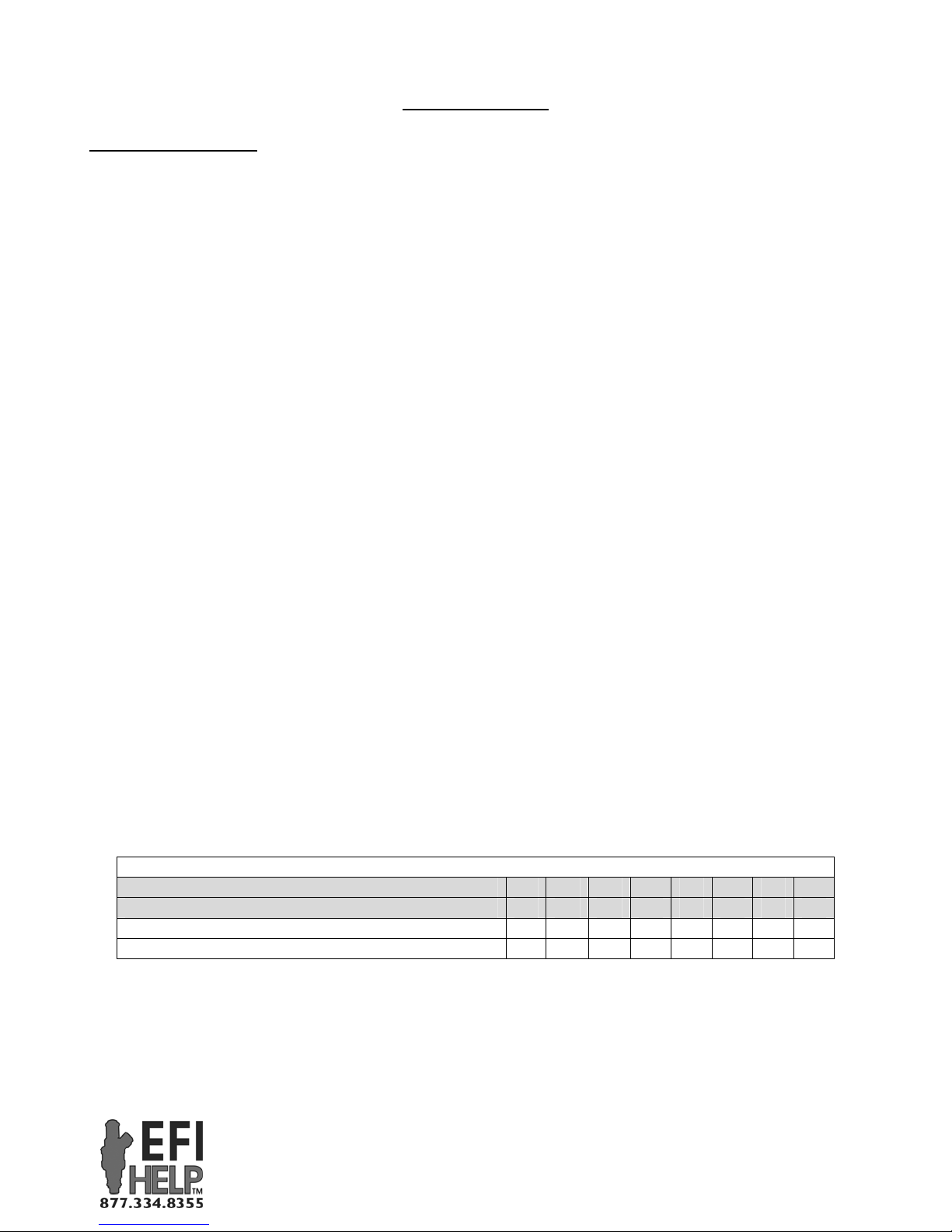
XIM™ EST/COIL Wiring (Coil per Cylinder) for Different Cam Signal Locations
EST/COIL Output A B C D E F G H
Sequence after Cam Input 1ST2
Cylinder # (SBC w/ Cam Before #1 Crank Signal) 1 8 4 3 6 5 7 2
Cylinder # (SBC w/ Cam Before #4 Crank Signal) 4 3 6 5 7 2 1 8
ND3RD4TH5TH
6TH 7
TH8TH
FAST™
3400 Democrat Rd.
Memphis, TN 38118
Phone: (901) 260-3278 Fax: (901) 375-3408
www.fuelairspark.com
Part #FAST4-101
Revised 7/9/07
Page 5
5
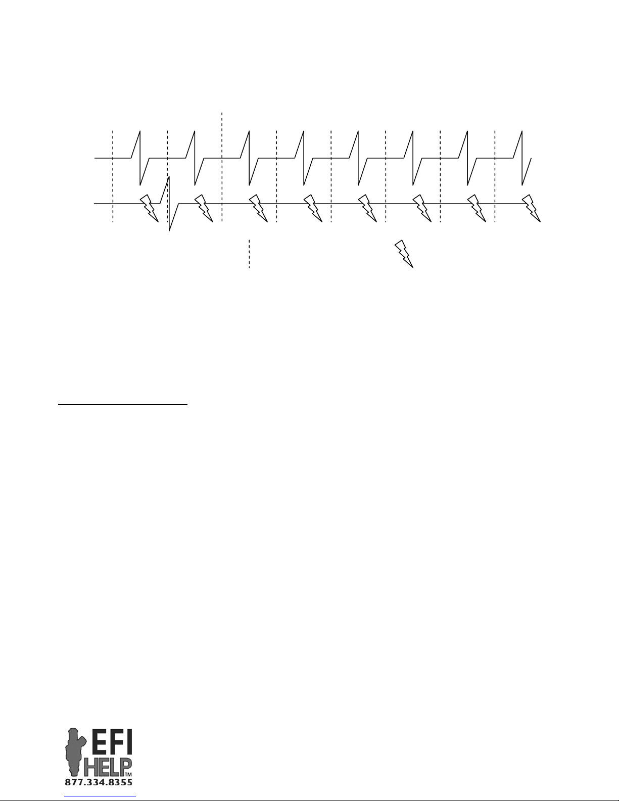
XIM™ – Crank Trigger Ignition Strategy
(One complete engine cycle shown for Small Block Chevy with 1-8-4-3-6-5-7-2 firing order)
50*
BTDC
Crank
Input
Cam
Input
EST/COIL
Output
60-130*
BTDC
= TDC (compression)
for each cylinder
= Spark, approx.
30* BTDC
(Shown at 90*)
In the case of a “waste spark” setup (one coil for every pair of companion cylinders), the same
principle is used to determine where EST/COIL output A will be wired. It goes to the coil that fires the
cylinder associated with the first crank signal after the cam input. Unlike a “coil per cylinder” setup,
the number of EST/COIL outputs used is only equal to half the number of cylinders. On a “waste
spark” V8, the XIM™ fires the first four EST/COIL outputs and then starts back over at A. The
sequence is: A–B–C–D–A–B–C–D-…
OE CRANK TRIGGER:
The OE Crank Trigger ignition strategy is designed for crank trigger wheels and pickups whose output
(1, 2, 3 or 4 evenly spaced pulses per revolution) occurs just ahead of TDC – as is the case with many
older factory ignition systems.
This ignition strategy is the same as the Crank Trigger ignition strategy except that it is intended for
use with a crank input between 1 and 10 degrees BTDC. The cam input still needs to occur between 10
and 80 degrees before the crank input. The EST/COIL outputs still fire in alphabetical order starting
with output A and EST/COIL output A still goes to the cylinder associated with the first crank signal
after the cam input.
FAST™
3400 Democrat Rd.
Memphis, TN 38118
Phone: (901) 260-3278 Fax: (901) 375-3408
www.fuelairspark.com
Part #FAST4-101
Revised 7/9/07
Page 6
6
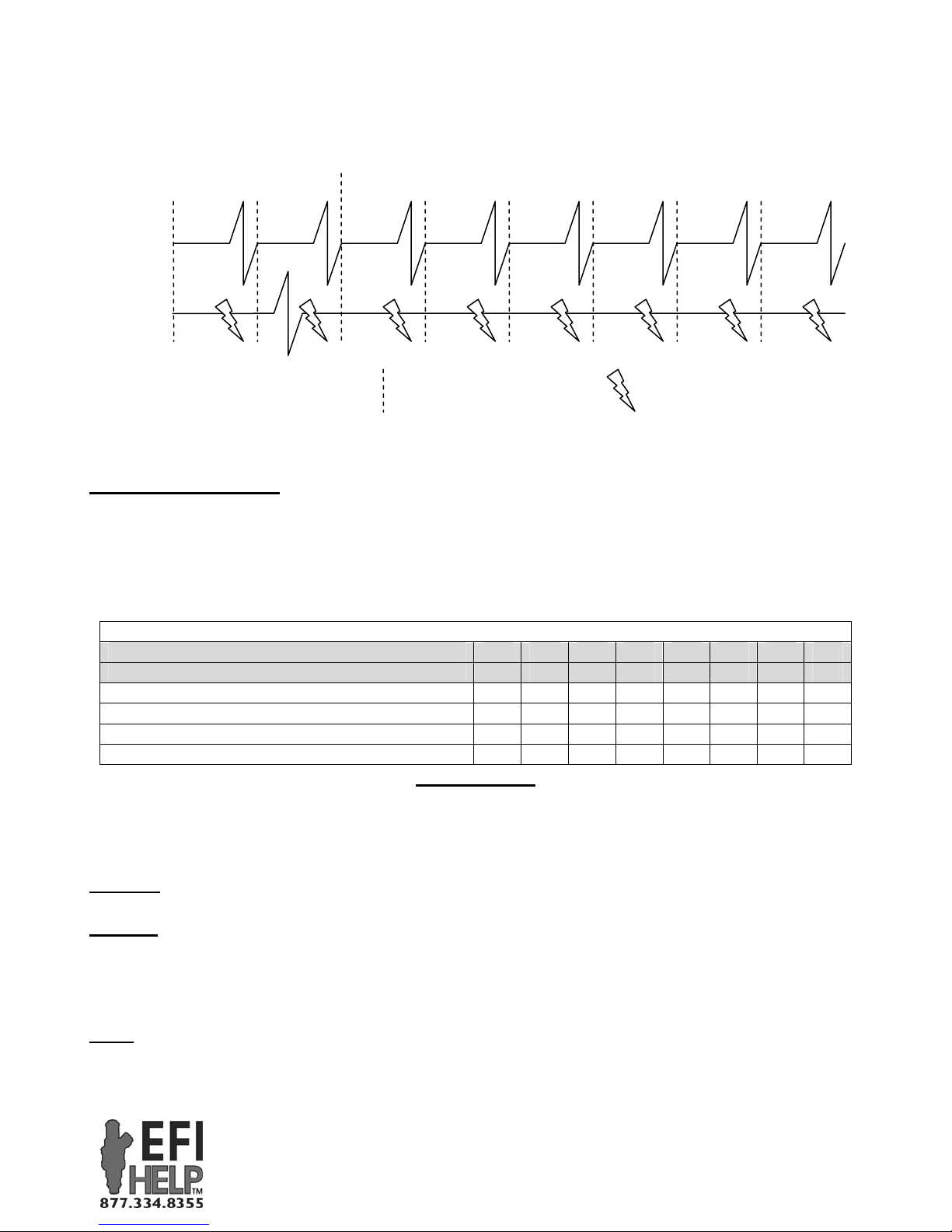
XIM™ – OE Crank Trigger Ignition Strategy
(One complete engine cycle shown for Small Block Chevy with 1-8-4-3-6-5-7-2 firing order)
1-10*
BTDC
Crank
Input
Cam
Input
EST/COIL
Output
11-90*
BTDC
= TDC (compression)
for each cylinder
= Spark, approx.
30* BTDC
(Shown at 60*)
FACTORY SPECIFIC: (Ford Mod, Hemi, LS1, etc.)
Newer factory engines have a variety of complicated trigger wheel arrangements. The XIM™ is preprogrammed to decode these different signal frames. Simply connect the factory crank and cam
pickups to the XIM™ and wire the EST/COIL outputs in the engine’s firing order. EST/COIL output
A always goes to cylinder #1.
XIM™ EST/COIL Wiring for Different Factory Engines
EST/COIL Output A B C D E F G H
Position in Firing Order 1ST 2ND 3RD 4TH 5TH 6TH 7TH 8TH
Cylinder # (Ford Mod, Waste Spark) - COIL 1&6 3&5 7&4 2&8
Cylinder # (Ford Mod, Coil per Cylinder) - COIL 1 3 7 2 6 5 4 8
Cylinder # (Chrysler Hemi) - COIL 1 8 4 3 6 5 7 2
Cylinder # (GM LS1/LS6 & LS2/LS7) - EST 1 8 7 2 6 5 4 3
External LEDs
The XIM™ features four LEDs built into its case. They are a valuable tool for confirming basic
functions.
POWER
– This LED lights up when the XIM™ is switched on.
CRANK
– This LED lights up while the XIM™ is receiving input from the crank sensor. If it is not lit
while the engine is turning over, you will need to find out why before the engine will run. Check that
the crank sensor is properly installed and plugged in. Also check for any wiring damage between the
crank sensor and the XIM™.
CAM – This LED flashes each time the XIM™ receives an input from the cam sensor. It will flash
relatively slowly during cranking. The flashing will become more rapid with increasing engine speed.
If it is not flashing while the engine is turning over, you will need to find out why before the engine
FAST™
3400 Democrat Rd.
Memphis, TN 38118
Phone: (901) 260-3278 Fax: (901) 375-3408
www.fuelairspark.com
Part #FAST4-101
Revised 7/9/07
Page 7
7
will run. Check that the cam sensor is properly installed and plugged in. Also check for any wiring
damage between the cam sensor and the XIM™.
STATUS – In normal operation, this LED lights up when the XIM™ has established CAN
communications with the XFI™ ECU. If it is not lit, check that the CAN LINK on the XIM™ harness
is connected (either directly or through an Interconnect Cable) to the CAN LINK on the XFI™
harness. Also verify that a Terminating Plug and Terminating Receptacle are connected to the open
ends of the CAN wiring.
A flashing status LED indicates that the XIM™ is in flash mode. This is used to update the software in
the XIM™. If flash mode was entered accidentally, make sure the FLASH wire is not touching ground
and power cycle the XIM™.
Setting up the C-Com XFI™ Software
Setting up the software in your FAST™ XFI™ to use the XIM™ is very simple. Select “IPU Ignition”
as the ignition type. Enter the “Crank Ref. Angle (*BTDC)” setting shown in the DIP switch table.
And finally, if using the Crank Trigger or OE Crank Trigger ignition strategies with the Cam input not
occurring before cylinder #1, change the “Cam Sync Precedes Cylinder:” setting. That setting remains
“1” for any of the Factory Specific ignition strategies. That’s all there is to do. Complete step by step
instructions are available under the Help menu in the C-Com XFI™ software under Section 6.0 Initial
Setup.
Flashing your XIM™
If it becomes necessary to update the software within the XIM™, the unit will need to be put into flash
mode. This is done by grounding the FLASH wire while turning on the XIM™. A flashing Status LED
will indicate that the XIM™ is in flash mode. An update utility will be provided that will send the new
software to the XIM™ through the communications cable that links the XIM™ (through the
CALPORT connector) to the laptop. Once the update has been sent, remove the FLASH wire from
ground and power cycle the XIM™ to complete the flashing process.
XIM™
Pin Function Wire Color
30-A1
30-A2
30-A3
30-B1
30-B2
30-B3
30-C1
30-C2
30-C3
30-D1
30-D2
30-D3
Inductive Crank Input Red
Discrete Crank Input Yellow
Crank Output Brown/White
Digital GND Black (/White)
Digital GND Black/White
Cam Output Yellow/Black
Inductive Cam Input Red
Discrete Cam Input Brown
Flash Enable Input Blue
Digital GND Black (/White)
Digital GND Black/White
Load Input*
XIM™ Pinout Chart
XIM™
Pin Function Wire Color
18-A1
18-A2
18-A3
18-B1
18-B2
18-B3
18-C1
18-C2
18-C3
18-D1
18-D2
18-D3
FAST™
3400 Democrat Rd.
Memphis, TN 38118
Phone: (901) 260-3278 Fax: (901) 375-3408
www.fuelairspark.com
+12V Switched Input Pink
User #1*
Digital GND Black/White
Battery Input Red
User #0*
N/A*
Coil Output A Orange
Auxiliary Output*
Power GND Black
Coil Output D Purple
Coil Output C Gray
Coil Output B Blue
Part #FAST4-101
Revised 7/9/07
Page 8
8
30-E1
30-E2
30-E3
30-F1
30-F2
30-F3
30-G1
30-G2
30-G3
30-H1
30-H2
30-H3
30-J1
30-J2
30-J3
30-K1
30-K2
30-K3
Analog 2 Input*
5V Reference Red/White
Analog GND Black/Pink
RS-232 RxD Black
RS-232 TxD Red
Dig GND (RS-232) White
CAN_H Yellow
CAN_L Green
Digital GND Black/White
EST Output A Purple
EST Output B Purple/White
Points Input*
EST Output C Red
EST Output E Blue/White
EST Output G Green/White
18-E1
18-E2
18-E3
18-F1
18-F2
18-F3
* Reserved for future use
Notes:
See letters and numbers molded into sides of
connectors to find pin locations.
“30-“ and “18-“ refer to 30 way and 18 way
connector.
EST Output D Red/White
EST Output F Green
EST Output H Blue
Coil Output E Black
Power GND Black
Power GND Black
Coil Output F Brown
Coil Output G Yellow
Coil Output H Green
Limited Warranty
FAST, Inc. warrants that all of its products are free from defects in material and workmanship for a period of 1
year from the date of purchase. This limited warranty shall cover the original purchaser.
FAST, Inc.’s obligation under this warranty is limited to the repair or replacement of its product. To make a
warranty claim, the part must be returned within 1 year of purchase to the address listed below, freight prepaid.
Items covered under warranty will be returned to you freight collect. It is the responsibility of the installer to
ensure that all of the components are correct before installation. We assume no liability for any errors made in
tolerances, component selection, or installation.
There is absolutely no warranty on the following:
•Any parts used in racing applications.
•Any product that has been physically altered, improperly installed or maintained.
•Any product used in improper applications, abused, or not used in conjunction with the proper parts.
•Damage due to excessive manifold pressure, i.e. nitrous backfires, engine misfire, etc.
There are no implied warranties of merchantability or fitness for a particular purpose. There are no
warranties, which extend beyond the description of the face hereof. FAST, Inc. will not be responsible for
incidental and consequential damages, property damage or personal injury damages to the extent permitted by
law. Where required by law, implied warranties or merchantability and fitness are limited to a term of 1 year
from the date of original purchase.
This warranty gives you specific legal rights and you may also have other legal rights, which vary from state to
state.
FAST™
3400 Democrat Rd.
Memphis, TN 38118
Phone: (901) 260-3278 Fax: (901) 375-3408
www.fuelairspark.com
Part #FAST4-101
Revised 7/9/07
 Loading...