

Page 1

HELMET OPERATOR’S MANUAL
© OPS-CORE 2016 06-05-160 REV. B
FOR FAST BALLISTIC
AND CARBON HELMETS
Page 2
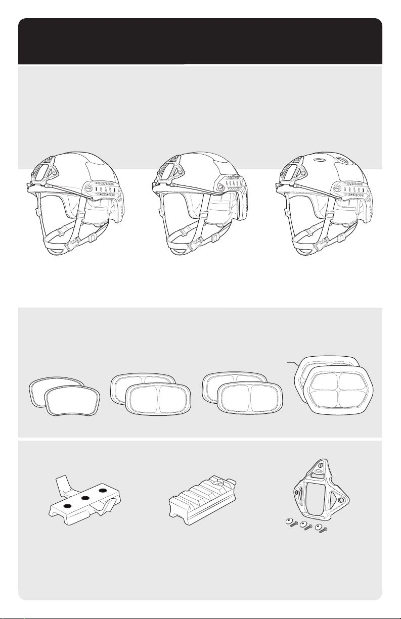
HELMET VERSIONS
FAST HELMETS
This manual is specific to the following helmet models: FAST Ballistic High Cut, FAST Ballistic Maritime
and FAST Carbon.
FAST Ballistic High Cut Helmet is used for reference drawings throughout this Operator’s Manual.
If there are any procedure discrepancies due to other helmet versions they will be specifically noted.
FAST BALLISTIC
HIGH CUT
FAST BALLISTIC
MARITIME
FAST CARBON
ALL HELMET VERSIONS INCLUDE:
(2) SIDE PADS, (2) 1/2” TOP PADS, (2) 3/4” TOP PADS, (1) 1/2“ REAR PAD, (1) 3/4” REAR PAD
3
/
4”
1
/
1
/
2”
SIDE PAD TOP PAD TOP PAD REAR PAD
WING-LOC
ADAPTER (1)
ADAPTER (1)
3
/
4”
SKELETON SHROUD PICATINNY
2”
2
Page 3

TABLE OF CONTENTS
4
HELMET COMPONENTS
SIZING GUIDE
5
6-7
8
9-15
16-22
PRO SETUP
CHINSTRAP OPERATION
ACCESSORY INTEGRATION
COUNTERWEIGHT & HELMET COVER
SKELETON SHROUD
FAST SIDE RAILS (ARCs)
EXTERIOR VELCRO
SIDE COVERS & GUNSIGHT MANDIBLE
COMMs HEADSET
MAINTENANCE SCHEDULE
REPLACEMENT KITS
REPLACEMENT FITBAND COMFORT PADS
REPLACEMENT FITBAND & EPP PADS
REPLACEMENT EXTERIOR VELCRO
®
23-26
27
28
REPLACEMENT SKELETON SHROUD
REPLACEMENT FAST SIDE RAILS
HELMET PART NUMBERS
REPLACEMENT PARTS / ACCESSORIES PART NUMBERS
WARNING & WARRANTY
OPERATOR NOTES
Page 4
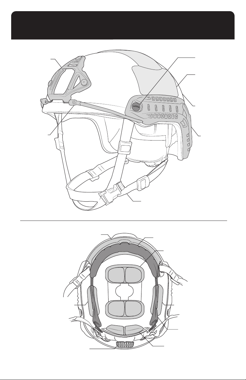
HELMET COMPONENTS
Skeleton Shroud
Bungee
Front EPP Pad
Integrated Retention System
(LED Version Available)
Note: LED = Left Eye Dominant
Comfort Pad
Ballistic Screws
& T-Nuts
Exterior Velcro
Helmet Shell
FAST Side
Rail (ARC)
Top EPP Pad
Side EPP Pad
Occ-Dial
Adjustment Knob
Side EPP Pad
Fitband
Rear EPP Pad
4
Page 5
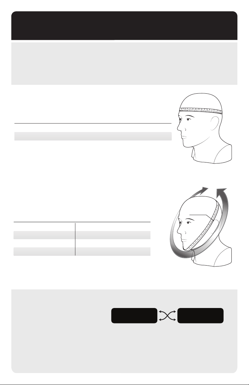
SIZING GUIDE
FAST helmets have been designed from the ground up to t the largest group of users in helmet
sizes that most closely match their heads. However, there is still a small percentage of users that
will not t our standard sizing congurations. Please use the sizing guide below to determine your
helmet size and your chinstrap size. If you require a non-standard chinstrap/helmet conguration,
custom solutions are available.
HELMET SIZING GUIDE
FAST HELMET SIZE
Head Circumference (cm)
Head Circumference (in)
Head Size (US)
S/M
53 - 56
20⁄ - 22
up to 7
M/L
56 - 59
22 - 23¼
up to 7⁄
L/XL
59 - 62
23¼ - 24⁄
up to 7⁄
CHINSTRAP SIZING GUIDE
S
ince people have different shaped heads, helmet size (the size
of the top of your head) is not always proportional
size (the size of your face).
FAST HELMET SIZE CHINSTRAP SIZE (in)
S/M
M/L
L/XL
XXL
MEDIUM
LARGE
X-LARGE
X-LARGE
to the chinstrap
24.5-27.5
26-29
27.5-30.5
27.5-30.5
XXL
62 - 64.5
24⁄- 25⁄
up to 8⁄
12
13
14
RUN MEASURING
TAPE ALONG FRONT
EDGE OF EAR
13
15
16
17
18
19
20
1
2
20
19
18
17
16
15
14
CUSTOM FIT COMBINATIONS
Your FAST Helmet can be custom fit
with an alternate
ordering or a replacement chinstrap
can be purchased separately.
chinstrap size upon
S/M HELMET WITH
LARGE CHINSTRAP
L/XL HELMET
WITH
MEDIUM CHINSTRAP
5
Page 6
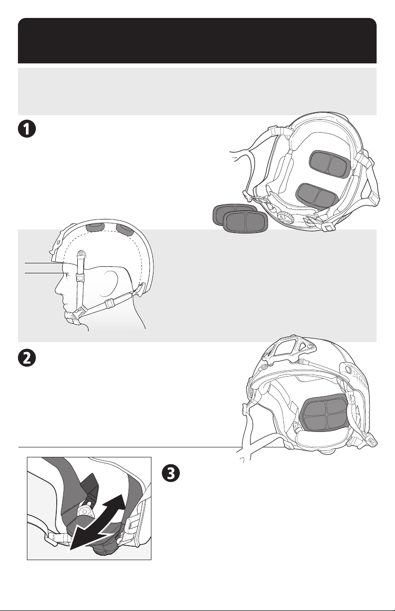
PRO SETUP
FAST Helmets were designed for professionals who expect the most from their equipment. Just like
fine-tuning the suspension on a racecar or sighting in a fire-arm, the helmet must be set up properly
before use to function correctly. If you do not follow these instructions, your helmet will not function
in accordance with stated performance.
ADJUST THE TOP PADS
• Put the helmet on. ½” pads come pre-installed
in the helmet. Turn the dial to loosen the fitband
so that all of the helmet weight is resting on top
of your head.
• With the fitband loose, check how high / low the
helmet is sitting. Forehead pad should be above and
not resting on the bony ridge of your eyebrows.
HEIGHT ADJUSTMENT
• The distance from the top of the eyebrow to the bottom of the
0.5”-1”
fitband should be approximately 0.5”- 1”. There should also be
enough room around your ears for COMMs / hearing protection.
• If the helmet sits too low on your head, remove the ½” top pads
and install the ¾” top pads.
• If the helmet sits at an uncomfortable angle, adjust the top pads,
or use a combination of ½” and ¾” top pads until it sits correctly.
ADJUST THE REAR PADS
• Install the ¾” rear pad. Put the helmet on.
• If you feel uncomfortable pressure on your forehead,
take the ¾” pad out and put in the ½”pad.
• If it feels the same as with the ½” pad (can’t notice
the difference) then keep the ¾” installed. This will
make the helmet more stable and comfortable.
6
ADJUST FITBAND HEIGHT
• Put the helmet on and turn the dial to tighten
the fitband until it feels secure. Look up at the
sky. If the dial digs into your neck, it is too low.
• You can adjust the height of the dial by sliding
the rear fitband liner tabs that attach it to the
inside of the shell up and down.
• Set the dial at the height that is most
comfortable for you.
Page 7
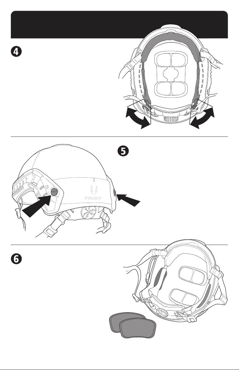
“PRE-LOAD” THE FITBAND
• You can set the shape of the fitband to
match the shape of your head for long
term comfort.
• Push or pull the rear fitband liner tabs
(used for height adjustment in step 3)
to adjust the fitband tension from a
round to more oval shape.
• Hold each rear fitband liner tab with
your hand in the location that sets the
fitband tension in the optimal shape
and then tighten the back screws to lock
the tabs in place.
TIGHTEN BACK SCREWS
• Tighten the back screws to lock the
rear fitband liner tabs, chinstrap and
side rails permanently in place.
• If you don’t do this, all of the
adjustments you just made will slip
and the helmet will likely come apart.
INSTALL THE SIDE PADS
• Install the side pads onto the Velcro patches
on the inside of the helmet. These pads
make the helmet more stable and increase
protection from side impacts.
• If they feel tight or uncomfortable, try to
relocate them into a position that feels good.
Note: Check that all screws
and accessory hardware are
tight and secure.
YOUR HELMET IS
READY FOR USE!
7
Page 8
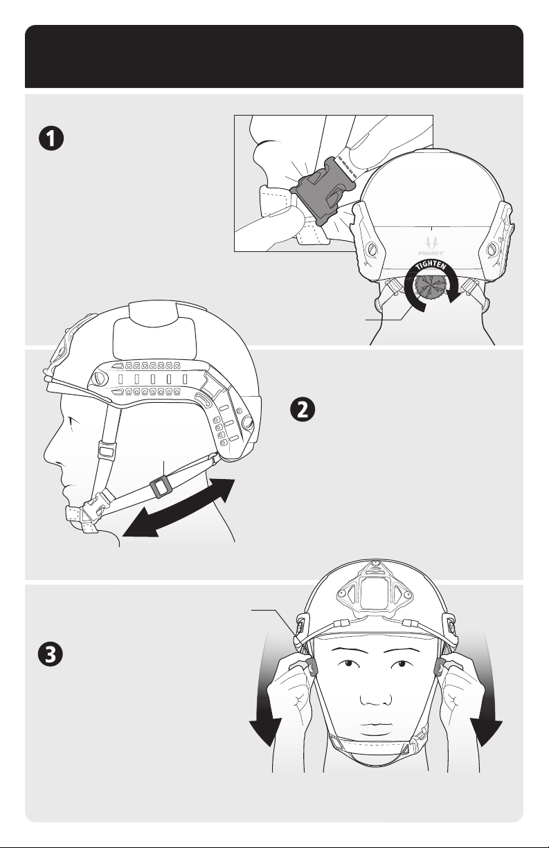
CHINSTRAP OPERATION
Put the helmet on and fasten
the Chinstrap Buckle. Turn the
Occ-Dial Adjustment Knob to
tighten the fitband until it is
comfortably snug.
Occ-Dial
Adjustment Knob
With both hands, pull the two Rear
Head-Loc® Sliders on the lower webbing
Rear
Head-Loc
Slider
straps toward your chin until snug.
Note: The technique works best if
you only hold the plastic sliders
and don’t touch the webbing.
Front Head-Loc Slider
With both hands, pull the two Front
Head-Loc Sliders on the webbing straps
that come from the front temples of the
helmet toward your chin until snug.
8
Page 9
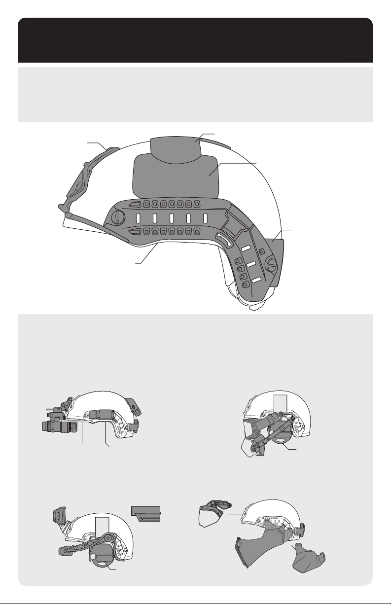
ACCESSORY INTEGRATION
There are three ways of attaching accessories to the FAST Helmet. The Ops-Core Skeleton Shroud or
VAS Shroud, FAST Side Rails (ARCs), and Exterior Velcro. These three components provide convenient
and secure ways to quickly attach and
personalized customization.
detach various accessories to different positions, and allow for
Skeleton Shroud
FAST Side Rail (ARC)
Top Exterior Velcro
Side Exterior
Velcro
Rear Exterior
Velcro
RECOMMENDED CONFIGURATIONS
There are numerous accessories that can be attached to your FAST Helmet to be used in a variety of
situations. Below are some recommended congurations.
NIGHT OPERATIONS AIRBORNE OPERATIONS
IFF Strobe
Counterweight
NVGs
Bungee
IR Illuminator
MISSION DOCUMENTATION
Video
Camera
HMD
Video
Camera
COMMs Headset
Goggles
O2 Mask
BREACHING / ATV
Ballistic
Visor
Ballistic
Mandible
COMMs Headset
Counterweight
Side
Armor
9
Page 10
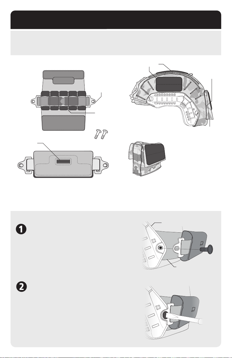
COUNTERWEIGHT & HELMET COVER
The Counterweight Kit reduces neck fatigue on long missions with night vision goggles or other accessories
that add weight to the front of the helmet. The Helmet Cover provides a variety of camouage options for
different environments.
(Open View)
Anchor for
Side Rail
Lead
Weight
Window for Mini
Glow Stick
(Closed View)
(2) 24mm Screws
COUNTERWEIGHT KIT
The Counterweight Kit Includes (1) Counterweight
Pack with (
COUNTERWEIGHT ATTACHMENT
REMOVE REAR SCREWS
Remove screws and T-nuts at back of FAST Side Rails.
Align the anchor of Counterweight to the holes on the rear
of the FAST Side Rail. The Rear Exterior Velcro will hold
Counterweight in place. Use your ngers to loosely attach
a screw to the Counterweight and FAST Helmet. Be sure
to place screw through Counterweight Anchor, Side Rail,
Helmet Shell, Fitband and Chinstrap Anchor. Repeat for
the opposite side.
5
) Lead Weights and (2) 24mm Screws.
Velcro
Detachable Rear Pouch
Fits ANVIS Battery Pack
Goggle
Retention
Flap
Rear Pouch
HELMET COVER
The Helmet Cover protects the shell outer
surface while still providing the functionalities
of the FAST platform.
FAST
Side Rail
Rear
Exterior Velcro
SECURE COUNTERWEIGHT
Use a screwdriver to tighten all screws from the outside
of the Counterweight, making sure the Counterweight is
securely fastened to the rear of the FAST Helmet.
Note: Adding weight to helmet increases risk of
neck strain and injury. Only add counterweight
when absolutely necessary to balance loads on
front of helmet.
10
Page 11
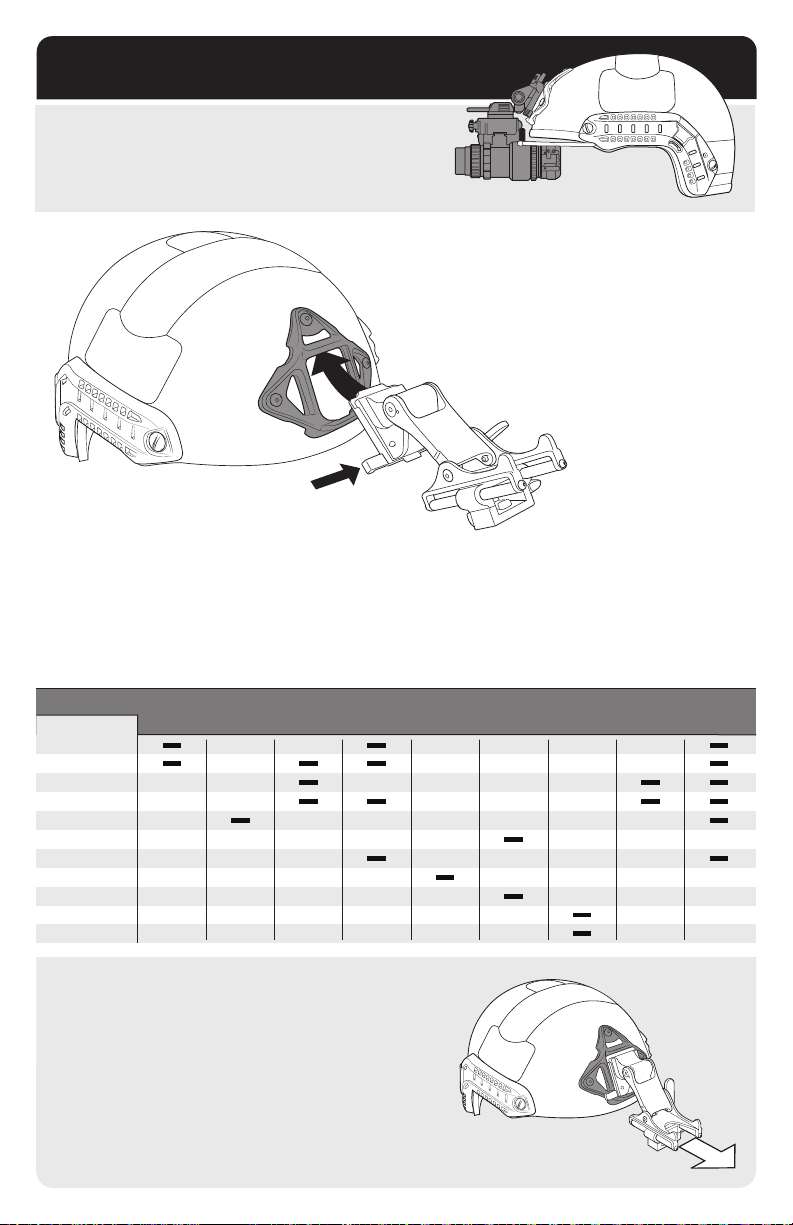
SKELETON SHROUD
The Skeleton Shroud provides a front mounting option
for video cameras, visors, illuminators, and night vision
goggles (NVG’s).
ATTACH NVG MOUNTING ARM
Insert and anchor the top of the NVG Mounting
Arm underneath the top of the bracket as shown.
While pressing the arm’s release trigger, push
down to snap and lock the arm in place.
SKELETON SHROUD & VAS SHROUD COMPATIBILITY
Helmet Compatability
Fits the standard MARSOC / WARCOM 3-hole NVG mount pattern
NVG & Mount Arm Compatability
Ops-Core NVG Shrouds are compatible with the following combinations of night vision goggle and
mount arm styles:
MOUNT ARM
NVG STYLE
PVS-7B/7D
PVS-14
PVS-15
PVS-18
PVS-21
PVS-23
PVS-7A/7C
LUCIE NVG
F5050
F4949
ANVS-6/9
US ARMY
STANDARD
#A3256368
WILCOX
L4 G21M
#28300G21M
®
WILCOX
L4 G24
#28300G24
®
WILCOX
L4 G25
#28300G25
®
WILCOX
L4 G29M
#28300G29M
®
WILCOX
L4 G01
#56500G01
®
WILCOX
L4 G02
#56500G02
®
NOROTOS
INVG
#1820010
®
NOROTOS
AKA2
#1840010
®
PULL TEST
Before attaching any NVG’s to the mount, give it a sturdy
tug in all directions to ensure it is properly secured.
Page 12
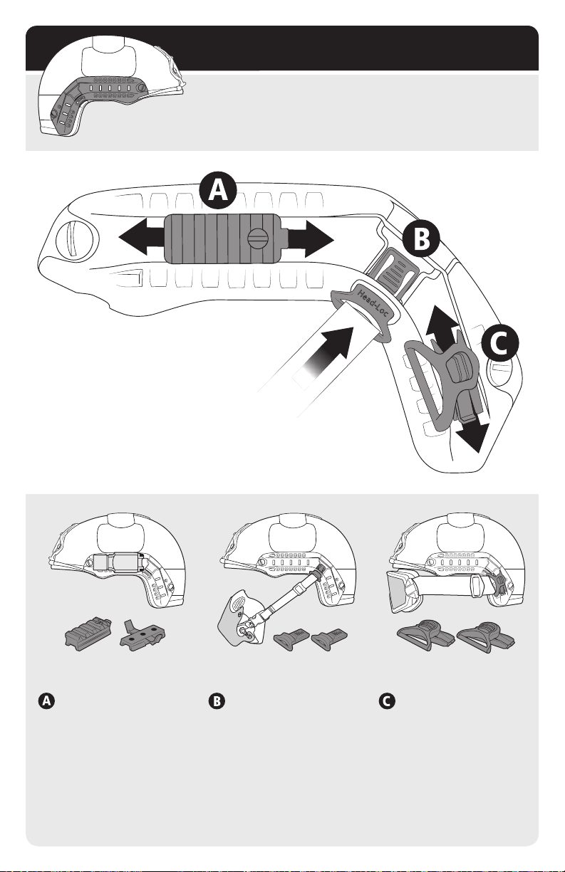
FAST SIDE RAILS (ARCs)
4-Position FAST Side Rails (ARCs) are mounted to the sides of the
helmet to allow for quick yet secure donning or dofng of various
headborne accessories.
ARC ADAPTERS
The three adapters shown on this FAST Side Rail are
commonly used for attaching accessories to the FAST
Helmets: Picatinny Adapter (A), O2 Single Strap Kit (B),
and 36mm Goggle Swivel Clip Kit (C).
Picatinny
Adapter
Wing-Loc
Adapter
TOP RAIL
Top Rail can accommodate
Picatinny Adapters, which
connect devices compatible
with 1911 Picatinny Rail,
and Wing-Loc Adapters,
which provide a base to
mount a variety of headborne
accessories.
12
O2 Strap Kit 36mm Goggle Swivel Clips
RAIL CORNER BACK RAIL
Rail corner allows for
instant and secure snap-in
attachment of Para-Flite
and Carleton O2 masks
with O2 Single Strap Kit.
Goggle Swivel Clips,
attached to your choice
of goggles, can quickly
clip into the back rail
while allowing freedom
of rotation.
Page 13
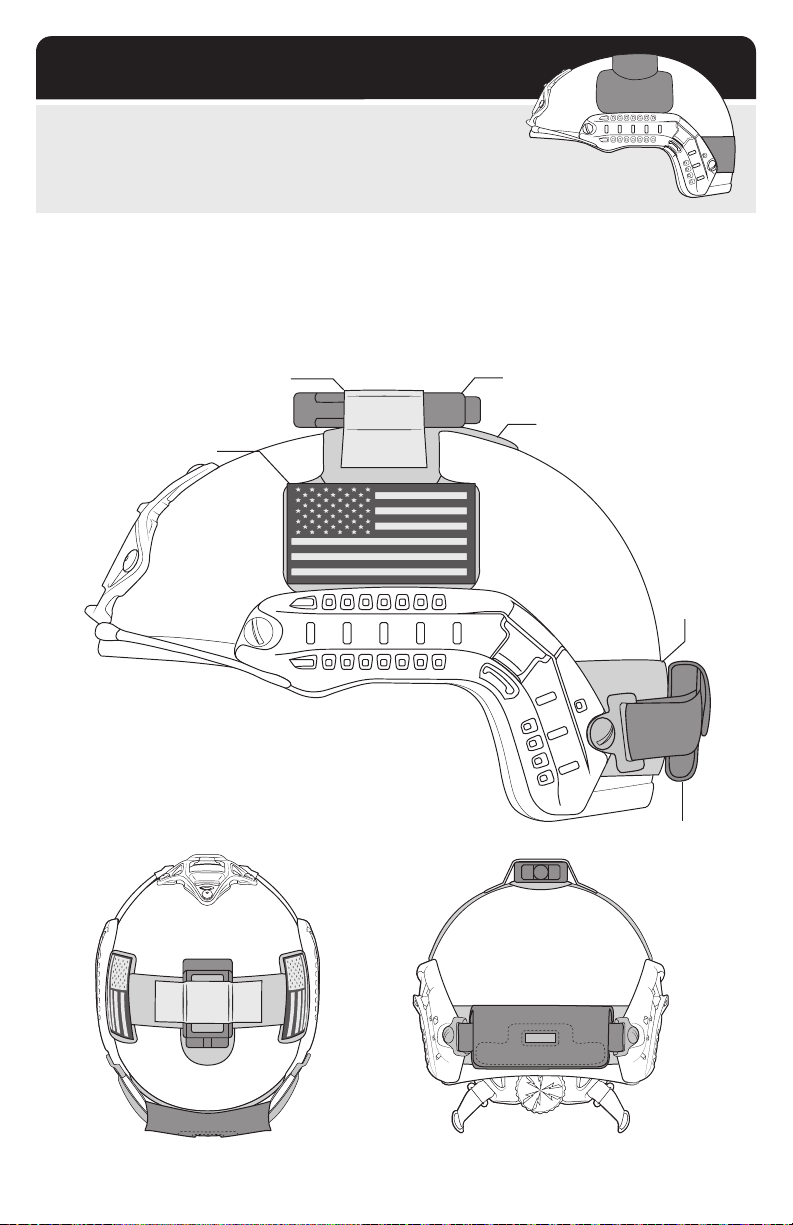
EXTERIOR VELCRO
®
Exterior loop Velcro is attached at the top, sides, and rear of the
FAST Helmet. The loop Velcro allows for easy mounting of accessories.
VELCRO ATTACHMENT
Apply hooked Velcro to the bottom of a device. Place device on top of the looped Velcro that is already
attached to the FAST Helmet. Cover top of device with additional hook Velcro to secure it into place.
Simply remove the device by pulling it away from the looped Velcro.
Note: Additional hook Velcro not included.
Additional Velcro IR Strobe
Top Exterior Velcro
Identity Patch
Rear
Exterior
Velcro
TOP VIEW REAR VIEW
Counterweight
13
Page 14
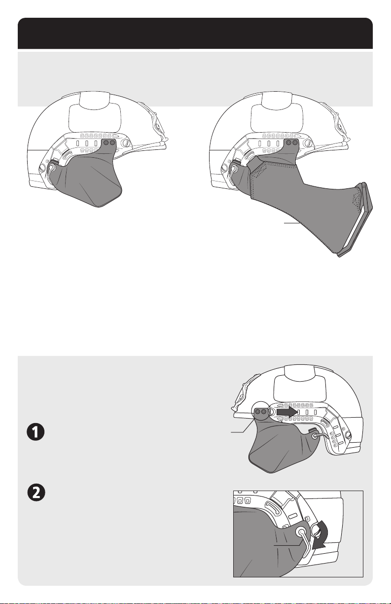
SIDE COVERS & GUNSIGHT MANDIBLE
The Up-Armor Side Covers and Gunsight Mandible are accessories that provide additional head coverage
that allows a user to quickly adjust the degree of protection to match different threat levels.
Edge Profile Clears
Rifle / Cheek Weld
UP-ARMOR SIDE COVERS
Up-Armor Side Covers are available in Ballistic
and Non-Ballistic versions. Both versions feature
a durable carbon ber exterior. The Non-Ballistic
version provides environmental protection, while
the Ballistic version is made from the same type
of materials as the FAST Ballistic helmet. *
* Note: Detailed threat performance specications are available at www.ops-core.com
Frame flexes for
Rifle / Cheek Weld
GUNSIGHT MANDIBLE
The mandible uses a combination of soft armor
and support frame technology to provide lower
face protection. It is designed to fold in half to
conveniently t into a rucksack. The exibility
allows a close cheek weld and causes minimum
interference with sighting shoulder weapons.
ATTACHMENT
The Up-Armor Side Covers, and Mandible attach to
the FAST Side Rails. Attachment is tool-less and takes
less than a minute. Follow the Up-Armor Side Cover
instructions below for attaching Mandible.
Front
SLIDE FRONT SHOE IN PLACE
Slide the Front Shoe of the Side Cover into the front
of the top FAST Side Rail (ARC) as shown.
LOCK SIDE COVERS IN PLACE
Snap the back of the Side Cover into the rear FAST
Side Rail (ARC) and turn the Cam-Loc Handle
downward to lock into place.
Shoe
Cam-Loc
Handle
14
Page 15
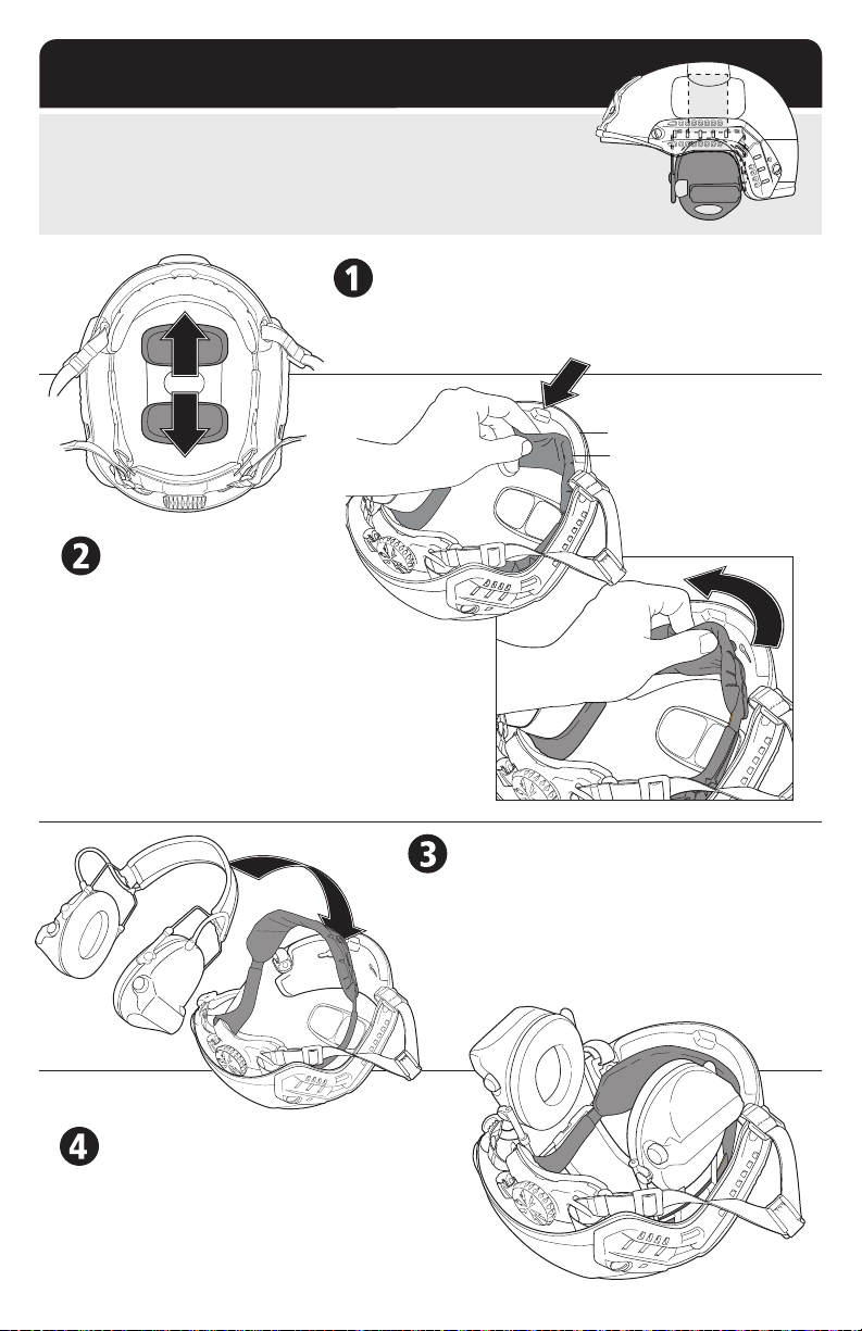
COMMs HEADSET
The liner system is compatible with a variety
hearing protection devices. Instructions for use with headband style
COMMs is below.
of COMMs headsets and
RELOCATE TOP PADS
Position the top pads in the helmet so there is enough space for
the headband of the headset to sit in between them.
DETACH FITBAND
Place your index nger behind the center
of the Fitband Comfort Pad and carefully
bend away from the Front EPP Pad as shown.
Pinch the Fitband Comfort Pad and use your thumb
to slide the pad sideways ½” towards the center of the
helmet along the Front EPP Pad. Repeat on both sides
until the pad is released from the key slots.
Note: Do not pull the Fitband Comfort Pad away
from the Front EPP Pad or you may break the
Front EPP Pad Key Slots.
Front EPP Pad
Fitband Comfort Pad
INSERT HEADSET HEADBAND
Flip the Comfort Pad / Fitband away from the front
impact liner and slide the headset headband around
it as shown. This will position the headset’s headband
on the outside of the helmet Fitband so that it does not
create a pressure point when you tighten the
Occ-Dial Adjustment Knob.
REATTACH FITBAND
Reattach the Comfort Pad / Fitband to the key-slots in
the front impact liner by bending the pad in the center
and pushing on the rivets (one at a time) with your
thumb while at the same time sliding them toward the
sides of the helmet.
15
Page 16

MAINTENANCE SCHEDULE
RECOMMENDED MAINTENANCE: ALL USERS
• Clean the helmet with a mild detergent and water.*
• Check that the chinstrap screws are tight using a athead screwdriver.
• Clean the Velcro for dust and dirt by using air pressure.
• Visually check the Skeleton Shroud or VAS Shroud and FAST Side Rails for signs of breakage.
• Visually check the Fitband for signs of breakage.
• Check that the Occ-Dial Adjustment Knob works properly.
• Check that the chinstrap does not have any damage and that the buckle latches and releases
properly.
*The whole helmet can be rinsed in fresh water.
Note: If any defects are found, the damaged components should be replaced
before use.
RECOMMENDED MAINTENANCE: ACTIVE DUTY
(Defined as soldiers who use their helmet 1440 hours/year or more)
• Replace Fitband Comfort Pads every 100 days or once/year.
• Replace Fitband, Chinstrap, Hardware, and EPP Pads after 2 years.
• Replace Exterior Velcro and repaint shell after 4 years.
• Replace other components if damaged / worn out as needed.
RECOMMENDED MAINTENANCE: NATIONAL GUARD
• Replace all items on as-needed basis and based on inspection.
• Replace Exterior Velcro and repaint the shell after 4 years.
16
Page 17
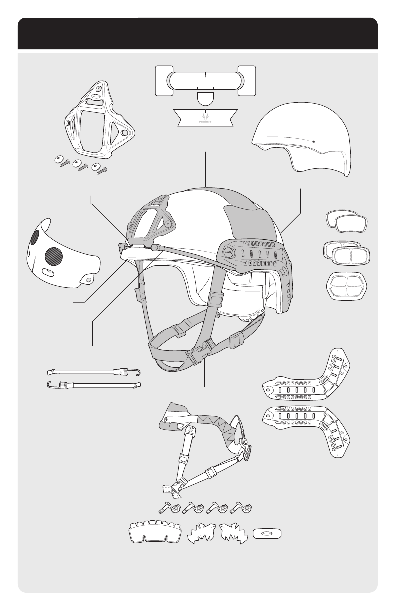
REPLACEMENT KITS
Exterior
Velcro
Front
EPP Pad
Skeleton
Shroud Kit
Bungees Kit
Repaint Helmet Shell
EPP
Pad Kit
FAST Side
Rails (ARCs)
Fitband Chinstrap & Hardware
Fitband Comfort Pads
17
Page 18
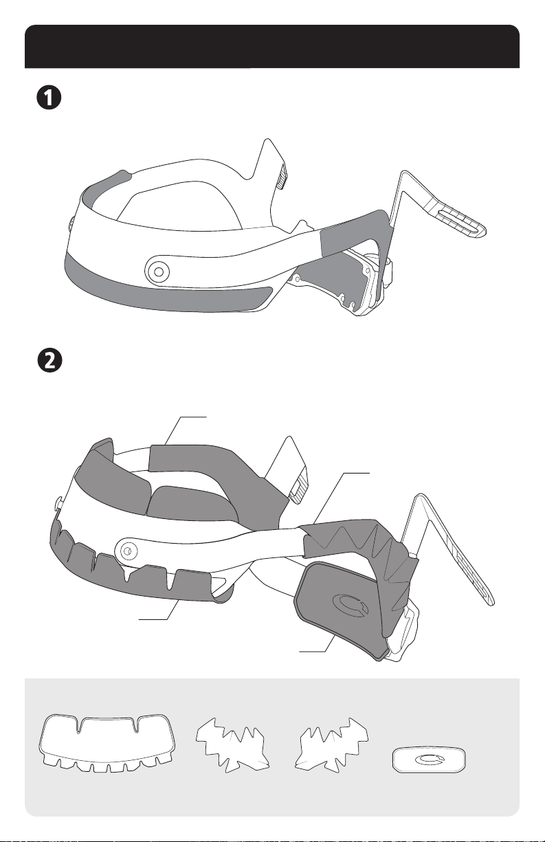
REPLACEMENT FITBAND COMFORT PADS
REMOVE OLD COMFORT PADS
Simply peel off all old comfort pads from the tband. A tband with all comfort pads removed should
look like the image below.
COMFORT PAD INSTALLATION
Attach the new comfort pads based on the instructions that came with the “Replacement Fitband
Comfort Pads Installation Instructions” manual.
Right Side Comfort Pad
Front Comfort Pad
Nape Comfort Pad
KIT INCLUDES THE FOLLOWING COMFORT PADS:
18
Front
Comfort Pad
Left Side
Comfort Pad
Right Side
Comfort Pad
Left Side Comfort Pad
Nape
Comfort Pad
Page 19
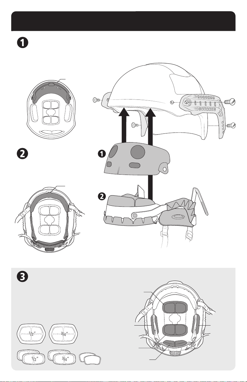
REPLACEMENT FITBAND & EPP PADS
REPLACEMENT FRONT
EPP PAD KIT:
The Front EPP Pad is inserted
into the helmet shell before the
Fitband. It is held into the helmet
shell by Velcro patches.
Front EPP
Pad Location
REPLACEMENT FITBAND:
The replacement Fitband kit
attaches to the Front EPP Pad.
Reassemble helmet as shown.
Fitband
Location
EPP PAD REPLACEMENT KIT
Install the pads onto the Velcro patches on the
inside of the helmet as shown. The Top and Rear
Pads come in two different thicknesses. Use the
pad that ts the best. See pages 6-7.
KIT INCLUDES THE FOLLOWING EPP PADS:
Side Pad Side Pad
Top Pad
Top Pad
Back Pad
19
Page 20
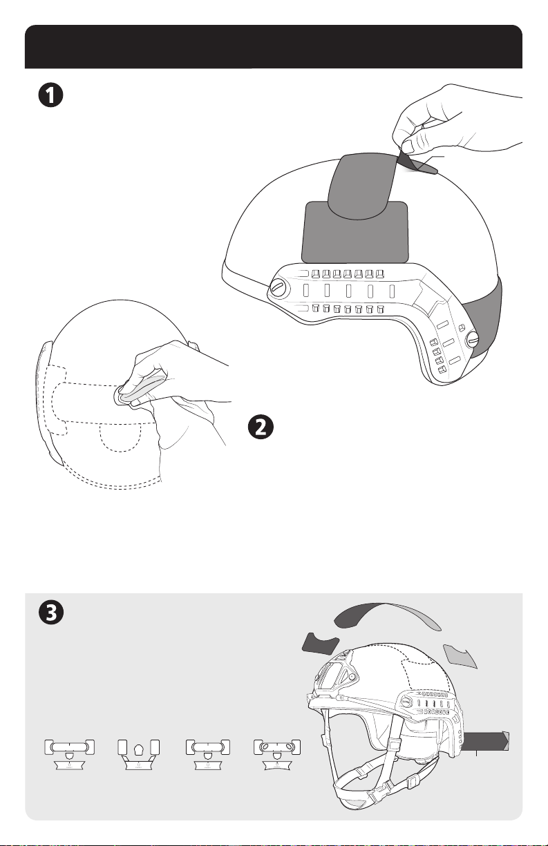
REPLACEMENT EXTERIOR VELCRO
CAREFULLY REMOVE OLD VELCRO
Note: It may be easier to remove Velcro by heating the helmet
shell to 70oc using a hair dryer. Do not heat helmet above 70oc
or helmet will be seriously damaged.
Using your ngers, carefully peel the Velcro away
from the helmet shell. DO NOT BRISKLY
RIP THE VELCRO OFF! Continue this
process by slowly pulling it back until all
Velcro is removed.
CLEAN THE HELMET SHELL
To remove excess adhesive from old Velcro and to ensure
optimal adhesion of new Velcro, gently rub affected areas
with a clean towel and Isopropyl Rubbing Alcohol. Do not
use harsh chemicals. If traces of adhesive remain, you can
use Goo Gone® to remove stubborn residue. Wipe the area
with alcohol again after use. Allow the helmet to dry before
attempting to place new Velcro onto the shell’s surface.
Slowly
Peel Back
PLACEMENT PREPARATION
Using the diagram to the right, carefully align Velcro
pieces to their proper positions. Test t all pieces before
removing backing. Adhesive on this Velcro is pressure
sensitive. Once in place it needs to be pressed down
rmly. Please allow up to 24 hours for adhesive to reach
maximum bonding strength.
KITS INCLUDE THE FOLLOWING REPLACEMENT PARTS:
FAST High Cut FAST Carbon
Kit A Kit B
FAST Maritime
Top Exterior
Velcro
Side
Exterior
Velcro
Rear
Exterior Velcro
Page 21
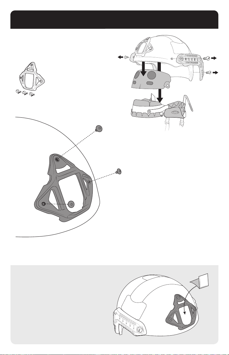
REPLACEMENT SHROUD
Before replacing Skeleton Shroud or VAS Shroud, the
helmet’s Fitband and Front EPP Pad must be removed.
Replacement kit includes
(1) Skeleton Shroud, (3)
Screws and (3) T-nuts.
Align the Skeleton Shroud or VAS
Shroud with the existing 3-hole pattern
on the front of your helmet. Insert a
T-nut through the Shroud’s top hole
from the front (outside) of the helmet
shell and use your ngers to loosely
attach a screw from the inside of helmet
shell. Repeat for remaining 2 holes.
BUMPER INSTALLATION
The optional foam backer is included to
stick on the back of the mount arm plate.
This backer can reduce wiggle or vibration
between the shroud, mount arm, and helmet.
Finish by using a screwdriver to tighten
all 3 screws from the inside of shell,
making sure the Shroud is securely
fastened to the helmet.
Note: Tighten screws by hand until
secured. Do not over tighten, this
will cause deformation to helmet
shell and compromise helmet’s
ballistic capabilities.
21
Page 22
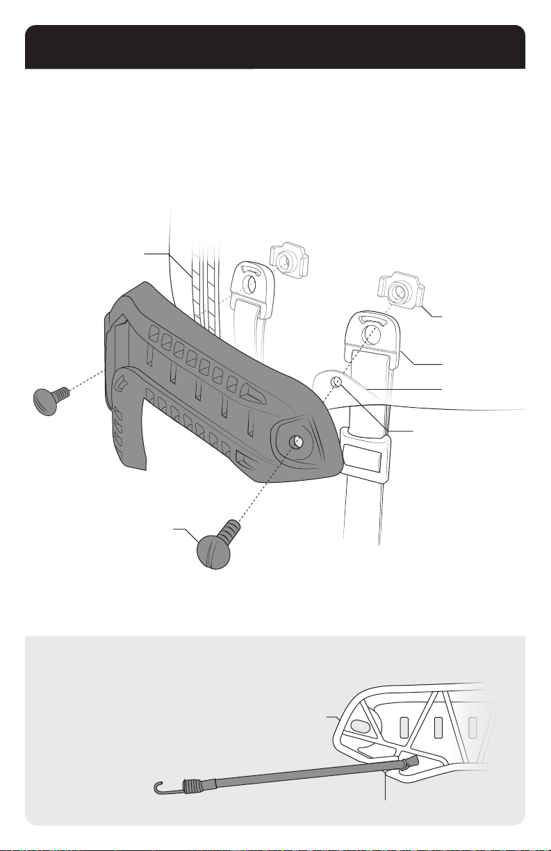
REPLACEMENT FAST SIDE RAILS
Align the new FAST Side Rails with the existing Chinstrap Holes on your FAST helmet. Loosely
assemble the FAST Side Rails, Helmet Chinstrap Anchors, and new hardware by following the
diagram below. For the rear assembly be sure to include the Rear Fitband Tab as shown. Repeat for
opposite side of helmet. Once all components are loosely assembled, nish by using a screwdriver to
tighten the two front screws.
Rear Fitband
Tab
Leave rear screws loose before executing instructions on pages 6-7.
T-Nut
Chinstrap
Anchor
Front EPP Pad
Screw Tab
Front Shell Hole
Screw
BUNGEE INSTALLATION
Insert the bungee ends into the FAST Side Rail’s Bungee
Retention Slot before assembly.
Side Rail
(Inside Shown)
22
Bungee Retention Slot
Page 23
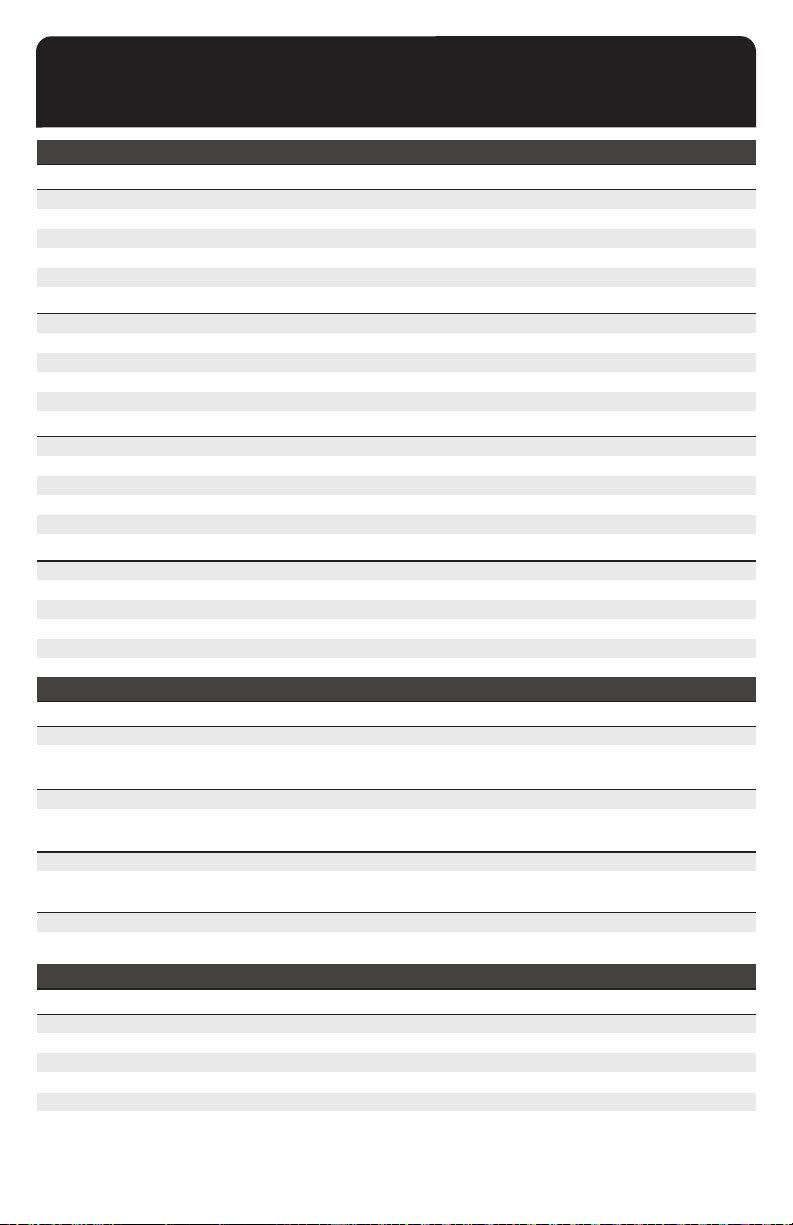
HELMET PART NUMBERS
FAST BALLISTIC HIGH CUT HELMET Note: LED
FAST BALLISTIC HIGH CUT
TAN
GREEN
BLACK
MULTICAM
DESERT MARPAT
FAST BALLISTIC HIGH CUT
TAN
GREEN
BLACK
MULTICAM
DESERT MARPAT
FAST BALLISTIC HIGH CUT
TAN
GREEN
BLACK
MULTICAM
DESERT MARPAT
FAST BALLISTIC HIGH CUT
TAN
GREEN
BLACK
MULTICAM
DESERT MARPAT
(NO SHROUD)
(W/ MOUNTED SHROUD)
(LED NO SHROUD)
(LED W/ MOUNTED SHROUD)
S/M
69-99-121
69-99-122
69-99-123
69-99-129
69-99-128
S/M
69-99-221
69-99-222
69-99-223
69-99-229
69-99-228
S/M
69-99-321
69-99-322
69-99-323
69-99-329
69-99-328
S/M
69-99-421
69-99-422
69-99-423
69-99-429
69-99-428
M/L
69-99-141
69-99-142
69-99-143
69-99-149
69-99-148
M/L
69-99-241
69-99-242
69-99-243
69-99-249
69-99-248
M/L
69-99-341
69-99-342
69-99-343
69-99-349
69-99-348
M/L
69-99-441
69-99-442
69-99-443
69-99-449
69-99-448
L/XL
69-99-151
69-99-152
69-99-153
69-99-159
69-99-158
L/XL
69-99-251
69-99-252
69-99-253
69-99-259
69-99-258
L/XL
69-99-351
69-99-352
69-99-353
69-99-359
69-99-358
L/XL
69-99-451
69-99-452
69-99-453
69-99-459
69-99-458
FAST BALLISTIC MARITIME HELMET
FAST BALLISTIC MARITIME
TAN
MULTICAM
FAST BALLISTIC MARITIME
TAN
MULTICAM
FAST BALLISTIC MARITIME
TAN
MULTICAM
FAST BALLISTIC MARITIME
TAN
MULTICAM
(NO SHROUD)
(W/ MOUNTED SHROUD)
(LED NO SHROUD)
(LED W/ MOUNTED SHROUD)
S/M
72-99-121
72-99-129
S/M
72-99-221
72-99-229
S/M
72-99-521
72-99-529
S/M
72-99-621
72-99-629
M/L
72-99-141
72-99-149
M/L
72-99-241
72-99-249
M/L
72-99-541
72-99-549
M/L
72-99-641
72-99-649
L/XL
72-99-151
72-99-159
L/XL
72-99-251
72-99-259
L/XL
72-99-551
72-99-559
L/XL
72-99-651
72-99-659
=
Left Eye Dominant
69-99-181
69-99-182
69-99-183
69-99-189
69-99-188
69-99-281
69-99-282
69-99-283
69-99-289
69-99-288
69-99-381
69-99-382
69-99-383
69-99-389
69-99-388
69-99-481
69-99-482
69-99-483
69-99-489
69-99-488
XXL
XXL
XXL
XXL
FAST CARBON HELMET
FAST CARBON
TAN
GREEN
BLACK
MULTICAM
DESERT MARPAT
(NO SHROUD)
S/M
59-99-121
59-99-122
59-99-123
59-99-129
59-99-128
M/L
59-99-141
59-99-142
59-99-143
59-99-149
59-99-148
L/XL
59-99-151
59-99-152
59-99-153
59-99-159
59-99-158
Page 24
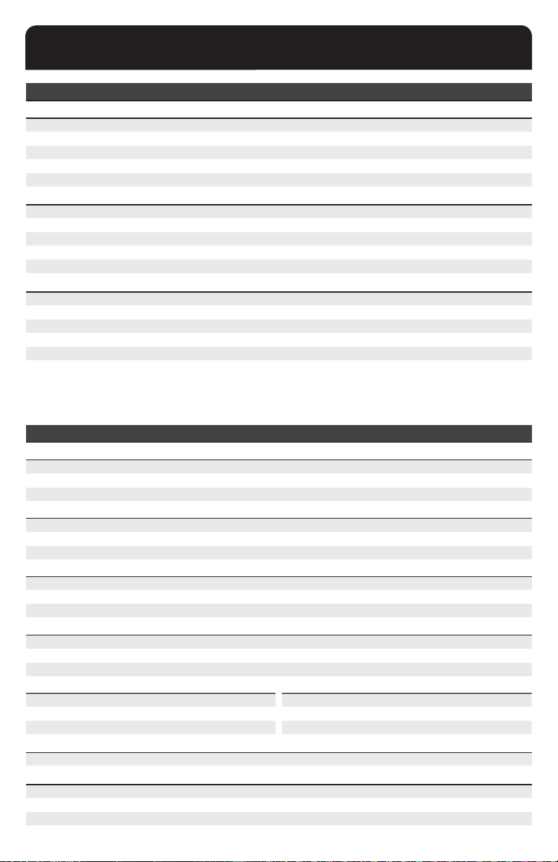
HELMET PART NUMBERS (CONTINUED)
FAST CARBON HELMET (CONTINUED)
FAST CARBON
TAN
GREEN
BLACK
MULTICAM
DESERT MARPAT
FAST CARBON
TAN
GREEN
BLACK
MULTICAM
DESERT MARPAT
FAST CARBON
TAN
GREEN
BLACK
MULTICAM
DESERT MARPAT
REPLACEMENT / ACCESSORIES
FAST BALLISTIC REPLACEMENT PARTS
REPLACEMENT FITBAND, CHINSTRAP & HARDWARE
TAN
GREEN
BLACK
REPLACEMENT FITBAND, CHINSTRAP & HARDWARE
TAN
GREEN
BLACK
REPLACEMENT EXTERIOR VELCRO
TAN
GREEN
BLACK
REPLACEMENT FAST SIDE RAILS (ARCs)
TAN
GREEN
BLACK
REPLACEMENT FAST SIDE RAILS (ARCs)
TAN
GREEN
BLACK
REPLACEMENT BALLISTIC HARDWARE KIT 22MM
(1) Pack = (4) 22mm Screws + (4) T-Nuts
REPLACEMENT FAST BALLISTIC BUNGEES
TAN
GREEN
BLACK
(W/ MOUNTED SHROUD)
(LED NO SHROUD)
(LED W/ MOUNTED SHROUD)
W/ BUNGEE
NO BUNGEE
M/L
59-99-241
59-99-242
59-99-243
59-99-249
59-99-248
M/L
59-99-341
59-99-342
59-99-343
59-99-349
59-99-348
M/L
59-99-441
59-99-442
59-99-443
59-99-449
59-99-448
M/L
60-99-141
60-99-142
60-99-143
M/L
60-99-241
60-99-242
60-99-243
L/XL
59-99-251
59-99-252
59-99-253
59-99-259
59-99-258
L/XL
59-99-351
59-99-352
59-99-353
59-99-359
59-99-358
L/XL
59-99-451
59-99-452
59-99-453
59-99-459
59-99-458
L/XL
60-99-151
60-99-152
60-99-153
L/XL
60-99-251
60-99-252
60-99-253
(LED)
S/M
59-99-221
59-99-222
59-99-223
59-99-229
59-99-228
S/M
59-99-321
59-99-322
59-99-323
59-99-329
59-99-328
S/M
59-99-421
59-99-422
59-99-423
59-99-429
59-99-428
S/M
60-99-121
60-99-122
60-99-123
S/M
60-99-221
60-99-222
60-99-223
L/XLM/LS/M XXL
60-96-121
60-96-122
60-96-123
60-96-141
60-96-142
60-96-143
60-96-151
60-96-152
60-96-153
L/XLM/LS/M XXL
29-99-121
29-99-122
29-99-123
PART #
29-99-201
29-99-202
29-99-203
29-99-141
29-99-142
29-99-143
VAS SHROUD REPLACEMENT HARDWARE
TAN
GREEN
BLACK
29-99-151
29-99-152
29-99-153
PART # PART #
03-98-103
Bulk Pack = (100) 22mm Screws + (100) T-Nuts
L/XLM/LS/M
29-98-121
29-98-122
29-98-123
29-98-141
29-98-142
29-98-143
29-98-151
29-98-152
29-98-153
XXL
60-99-181
60-99-182
60-99-183
XXL
60-99-281
60-99-282
60-99-283
60-96-181
60-96-182
60-96-183
29-99-181
29-99-182
29-99-183
PART #
35-98-101
35-98-102
35-98-103
03-98-203
Page 25
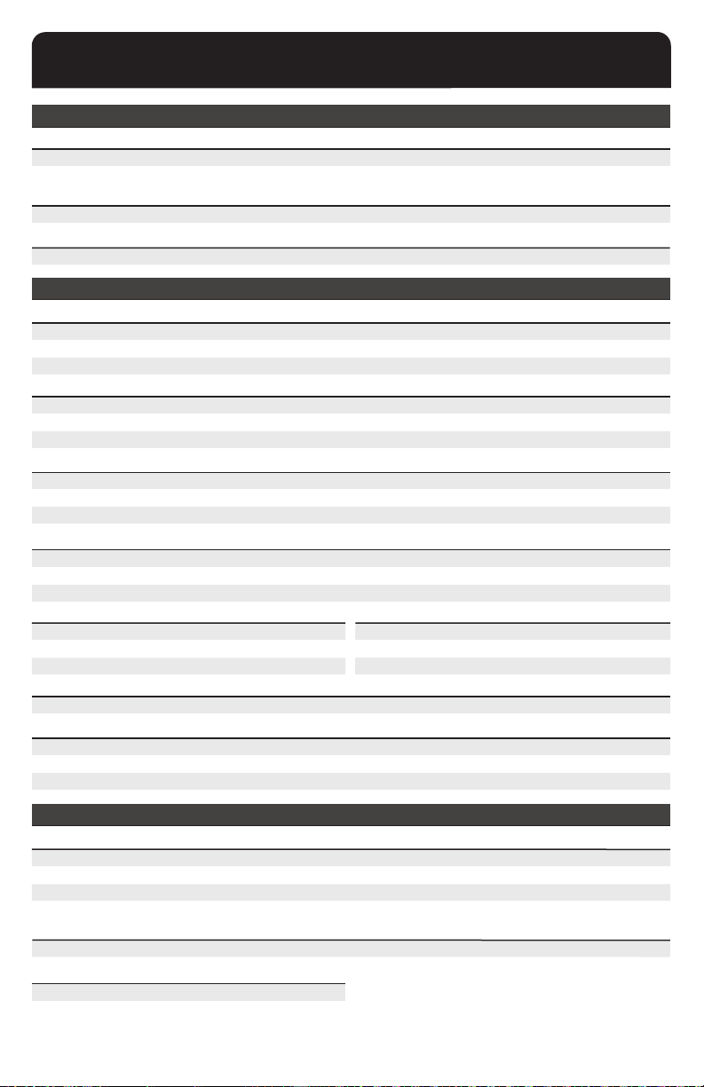
REPLACEMENT / ACCESSORIES
FAST MARITIME REPLACEMENT PARTS
REPLACEMENT EXTERIOR VELCRO L/XLM/LS/M
TAN KIT A
TAN KIT B
REPLACEMENT FAST SIDE RAILS (ARCs)
TAN
REPLACEMENT FAST SIDE RAILS (ARCs)
TAN
W/ BUNGEE
NO BUNGEE
60-96-421 60-96-441
60-96-521
29-99-521 29-99-541 29-99-551
60-96-541
PART #
29-99-601
FAST CARBON REPLACEMENT PARTS
REPLACEMENT FITBAND, CHINSTRAP & HARDWARE
TAN
GREEN
BLACK
REPLACEMENT FITBAND, CHINSTRAP & HARDWARE
TAN
GREEN
BLACK
60-95-121
60-95-122
60-95-123
(LED)
60-95-221
60-95-222
60-95-223
60-95-141
60-95-142
60-95-143
60-95-241
60-95-242
60-95-243
REPLACEMENT EXTERIOR VELCRO L/XLM/LS/M
TAN
GREEN
BLACK
REPLACEMENT FAST SIDE RAILS (ARCs)
TAN
GREEN
BLACK
REPLACEMENT FAST SIDE RAILS (ARCs)
TAN
GREEN
BLACK
WITH BUNGEE
NO BUNGEE
60-96-221
60-96-222
60-96-223
29-99-221
29-99-222
29-99-223
PART #
29-99-301
29-99-302
29-99-303
60-96-241
60-96-242
60-96-243
29-99-241
29-99-242
29-99-243
VAS SHROUD REPLACEMENT HARDWARE
TAN
GREEN
BLACK
REPLACEMENT BALLISTIC HARDWARE KIT 15MM PART # PART #
(1) Pack = (4) 15mm Screws + (4) T-Nuts
03-99-103
Bulk Pack = (100) 15mm Screws + (100) T-Nuts
REPLACEMENT FAST CARBON BUNGEES
TAN
GREEN
BLACK
29-98-221
29-98-222
29-98-223
29-98-241
29-98-242
29-98-243
60-96-451
60-96-551
L/XLM/LS/M
L/XLM/LS/M
60-95-151
60-95-152
60-95-153
L/XLM/LS/M
60-95-251
60-95-252
60-95-253
60-96-251
60-96-252
60-96-253
L/XLM/LS/M
29-99-251
29-99-252
29-99-253
PART #
35-96-101
35-96-102
35-96-103
03-99-203
L/XLM/LS/M
29-98-251
29-98-252
29-98-253
FAST BALLISTIC & CARBON REPLACEMENT PARTS
REPLACEMENT FRONT EPP PAD
S/M
M/L
L/XL
XXL
REPLACEMENT EPP PAD KIT
S/M & M/L (8 pads total, no front pad)
REPLACEMENT FITBAND COMFORT PADS
Black (4 pads total)
PART #
60-98-123
60-98-143
60-98-153
60-98-183
PART # PART #
60-98-203
L/XL (8 pads total, no front pad)
60-98-303
PART #
60-97-003
25
Page 26

REPLACEMENT / ACCESSORIES (CONTINUED)
FAST ACCESSORIES
ADAPTERS PART #
Picatinny Adapter
Wing-Loc Adapter
Single Clamp
X300 Adapter
O2 DOUBLE STRAP KIT
TAN
GREEN
BLACK
20-99-103
20-98-103
20-97-103
20-96-103
PART #
26-99-101
26-99-102
26-99-103
O2 SINGLE STRAP KIT PART #
TAN
GREEN
BLACK
26-99-301
26-99-302
26-99-303
SKELETON SHROUD FAST BALLISTIC PART #
TAN
GREEN
BLACK
VAS SHROUD FAST BALLISTIC
TAN
GREEN
BLACK
(HB26)
PART #
35-99-201
35-99-202
35-99-203
VAS SHROUD FAST CARBON PART #
TAN
GREEN
BLACK
35-99-401
35-99-402
35-99-403
COUNTERWEIGHT KIT PART #
TAN
39-99-101
FLEECE CHINCUP/ EXTENDER COVER PART #
BLACK
MESH HELMET COVER FOR FAST HIGH CUT
S/M MULTICAM
M/L MULTICAM
L/XL MULTICAM
19-99-203
PART #
41-98-229
41-98-249
41-98-259
HELMET BAG
M/L BLACK
L/XL BLACK
ADAPTERS PART #
19mm Swivel Clips & Shoes (2 per set)
36mm Swivel Clips & Shoes (2 per set)
Contour HD Adapter
UP-ARMOR SIDE COVERS BALLISTIC
TAN
GREEN
BLACK
20-95-203
20-95-103
20-94-103
PART #
37-99-101
37-99-102
37-99-103
UP-ARMOR SIDE COVERS NON-BALLISTIC PART #
TAN
GREEN
BLACK
37-99-201
37-99-202
37-99-203
XX-XX-XXX
XX-XX-XXX
XX-XX-XXX
CBRN MASK EXTENDER PART #
TAN
GREEN
BLACK
GUNSIGHT MANDIBLE
TAN
GREEN
BLACK
MULTICAM
MULTICAM
19-99-101
19-99-102
19-99-103
PART #
38-99-101
38-99-102
38-99-103
38-99-109
39-99-109
MESH HELMET COVER FOR FAST MARITIME PART #
S/M MULTICAM
M/L MULTICAM
L/XL MULTICAM
41-98-129
41-98-149
41-98-159
PART #
XX-XX-XXX
XX-XX-XXX
26
Page 27

7.62
5.56
WARNING
DOES NOT PROTECT
against 7.62 and
5.56 rounds
This helmet provides LIMITED protection for the head and does not offer any protection against neck, spinal, or certain types of
brain injuries including those caused by rotational forces. Some hazards can exceed this helmet’s ability to provide protection and
could cause severe head, brain, or spinal injuries including paralysis or death.
Remember: the higher the impact velocity, the greater the chance of injury / death. Common sense is the best defense.
NOT INTENDED
for motor
vehicle use
DOES NOT PROTECT
from extreme
hazards
SAFETY CHECKLIST:
Inspect the helmet before each use. Make sure the shell, liner pads, plastic hardware, stitching, chinstrap, and t system
components are not damaged, cracked, deformed, loose or showing signs of excessive wear. Do not remove or alter the front,
top, or back impact pads. Do not apply paint, solvents, or like products as they could degrade helmet integrity and resulting
performance. Replace your helmet if it is subjected to a signicant impact since the shell and/or liner pads could be damaged
without showing any obvious signs of a problem.
These instructions must be followed by all persons using or maintaining this helmet in order for it to perform as designed. Failure
to do so could result in equipment malfunction, serious injury or death.
WARRANTY
The FAST helmet shell is warranted for (5) years from date of purchase against material defects and/or faulty workmanship.
All other liner components including the Worm-Dial, head-band, pads, and chinstrap retention system are warranted for (1) year
from date of purchase against material defects and/or faulty workmanship.
This warranty is in lieu of all other warranties, expressed, implied, or statutory, and is strictly limited to the terms hereof: Ops-Core
specically disclaims any warranty of merchantability or of usefulness for a particular purpose.
The defective product must be returned to Ops-Core with proof of purchase and information describing the nature of the problem.
It is expressly agreed that the Purchaser’s sole and exclusive remedy for breach of the above warranty, for any tortious conduct of
Ops-Core, or for any other cause of action, shall be the repair, replacement, or credit, at Ops-Core’s discretion, of any components
or parts thereof, that after examination by Ops-Core are proven to be defective.
If it is determined by Ops-Core that the product’s failure was due to accident, abuse, misuse, neglect, improper maintenance, or
normal wear and tear, the product is not covered in this warranty.
Ops-Core shall be released from all obligations under this warranty in the event repairs or modications are made to any of the
parts by persons other than its own service personnel.
No agent, employee or representative of Ops-Core may bind Ops-Core to any afrmation, representation or modication of the
warranty concerning the goods sold under this contract.
Exclusion of Consequential Damages – Purchaser specically understands and agrees that under no circumstances will Ops-Core
be liable to Purchaser for economic, special, incidental, or consequential damages or losses of any kind whatsoever, including
but not limited to, loss of anticipated prots and any other loss caused by reason of non-operation of the goods. This exclusion is
applicable to claims for breach of warranty, tortious conduct or any other cause of action against Ops-Core.
27
Page 28
OPERATOR NOTES
MADE IN USA
 Loading...