

Page 1

Com.X
IP PBX / Gateway
Administrator Guide
(Com.X revision 1.4 software release)
Version 4.0.1, 19 September 2016
©2010 – 2014 Far South Networks
Page 2

Document History
Version Date Description of Changes
4.0.1 05/10/2016 Documented ported from 1.3 release
©2010 – 2016 Far South Networks
Page 3

Com.X Administrator Guide
Page 3
Table of Contents
1 INTRODUCTION ............................................................................................................................... 18
1.1 OVERVIEW ........................................................................................................................................ 18
2 MANAGING THE UNIT ................................................................................................................... 19
2.1 ACCESSING THE UNIT .......................................................................................................................... 19
2.1.1 Factory network configuration ............................................................................................. 19
2.1.2 Authentication ....................................................................................................................... 19
2.1.3 Remote web login .................................................................................................................. 19
2.1.4 Wanderweb Activation ........................................................................................................... 20
2.1.5 GUI layout ............................................................................................................................. 20
2.1.6 Configuration status .............................................................................................................. 21
2.1.7 Applying and reverting a configuration ................................................................................ 21
2.1.8 Changing the default administrator's password ................................................................... 22
2.1.9 Rebooting and Shutting down ............................................................................................... 23
2.2 SYSTEM MAINTENANCE ...................................................................................................................... 23
2.2.1 Backup and Restore ............................................................................................................... 23
2.2.1.1 Backup contents ........................................................................................................................... 24
2.2.1.1.1 Factory default configurations ............................................................................................. 24
2.2.1.1.2 Configuration, Recordings ................................................................................................... 24
2.2.1.1.3 Voicemail ............................................................................................................................. 24
2.2.1.1.4 CDR ..................................................................................................................................... 24
2.2.1.1.5 Excluded from backup ......................................................................................................... 24
2.2.1.2 Immediate backup ........................................................................................................................ 24
2.2.1.3 Scheduled backup ........................................................................................................................ 24
2.2.1.4 Managing existing backup archives ............................................................................................. 25
2.2.1.5 Restoring an archive onto the same system .................................................................................. 26
2.2.1.6 Restoring an archive onto a replacement system .......................................................................... 26
2.2.2 Licensing ............................................................................................................................... 28
2.2.2.1 Adding a License ......................................................................................................................... 28
2.2.3 Unlicensed Functionality ...................................................................................................... 30
2.2.4 ViBE Licensing ...................................................................................................................... 30
2.2.5 Updating the software ........................................................................................................... 30
2.2.5.1 Updating the PBX software ......................................................................................................... 30
2.2.5.1.1 Managing Packages from the GUI ....................................................................................... 31
2.2.5.2 Updating Packages ....................................................................................................................... 31
2.2.5.2.1 Check for updates ................................................................................................................ 31
2.2.5.2.2 Download Updates .............................................................................................................. 32
2.2.5.2.3 Install/Upgrade .................................................................................................................... 32
©2010 – 2016 Far South Networks
Page 4

Com.X Administrator Guide
Page 4
2.2.6 Upgrading a 1.3 system to 1.4 .............................................................................................. 32
3 COMMISSIONING THE UNIT ........................................................................................................ 33
3.1 GLOBAL SETTINGS .............................................................................................................................. 33
3.2 NETWORK CONFIGURATION .................................................................................................................. 36
3.2.1 Connections ........................................................................................................................... 36
3.2.2 Ethernet Interface Configuration .......................................................................................... 38
3.2.2.1 Listing ethernet interfaces ............................................................................................................ 38
3.2.2.2 Configuring an Interface .............................................................................................................. 38
3.2.2.3 Providing DHCP Server IP allocation to clients ........................................................................... 39
3.2.2.4 Providing Comma iTA boot services ............................................................................................ 41
3.2.3 Configuration of PPPoE Interfaces ...................................................................................... 42
3.2.4 X.21 Interface configuration ................................................................................................. 43
3.2.4.1 Frame Relay PVC Configuration ................................................................................................. 45
3.2.5 Creating Virtual ports for VLAN and PVC ........................................................................... 47
3.2.5.1 VLAN .......................................................................................................................................... 47
3.2.5.2 VPN Interface .............................................................................................................................. 50
3.2.5.2.1 VPN Server .......................................................................................................................... 51
3.2.5.2.1.1 Routes .......................................................................................................................... 52
3.2.5.2.1.2 Generating certificates for clients ................................................................................ 52
3.2.5.2.1.3 Revoking Client certificates ......................................................................................... 53
3.2.5.2.2 VPN Client .......................................................................................................................... 53
3.2.6 Adding IP Routes to Interfaces ............................................................................................. 55
3.2.6.1 Removing IP Routes from an Interface ........................................................................................ 55
3.3 FIREWALL CONFIGURATION .................................................................................................................. 56
3.3.1 Zones ..................................................................................................................................... 56
3.3.2 Policies .................................................................................................................................. 57
3.3.2.1 Applying Default Policies ............................................................................................................ 58
3.3.2.2 Managing Policies ........................................................................................................................ 59
3.3.2.3 Editing Policies ............................................................................................................................ 59
3.3.2.4 Creating a New Policy ................................................................................................................. 60
3.3.3 Rules ...................................................................................................................................... 61
3.3.3.1 Port Forward ................................................................................................................................ 61
3.3.3.2 Inbound Redirect ......................................................................................................................... 63
3.3.3.3 Inbound Access ............................................................................................................................ 64
3.3.3.4 Ping .............................................................................................................................................. 65
3.3.3.5 Blacklist ....................................................................................................................................... 66
3.3.4 Advanced ............................................................................................................................... 66
3.3.5 Failed Rules .......................................................................................................................... 66
3.3.6 Network Quality of Service ................................................................................................... 67
3.3.6.1 Loading network QoS defaults ..................................................................................................... 67
©2010 – 2016 Far South Networks
Page 5

Com.X Administrator Guide
Page 5
3.3.6.2 Editing classification and priority ................................................................................................ 68
3.4 HARDWARE DEVICE CONFIGURATION ..................................................................................................... 68
3.4.1 Configured devices ................................................................................................................ 69
3.4.2 Detecting and scanning for devices ...................................................................................... 69
3.4.3 Adding Detected Devices ...................................................................................................... 69
3.4.4 Manually adding devices ...................................................................................................... 70
3.4.5 Configuring devices .............................................................................................................. 70
3.4.5.1 Configuring Comma devices ........................................................................................................ 70
3.4.5.2 Configuring Generic devices ........................................................................................................ 72
3.5 MANAGED SIP PHONE PROVISIONING ..................................................................................................... 73
3.5.1 Adding Hardware (Managed SIP Device) ............................................................................ 74
3.5.1.1 Manually add Managed SIP Phone .............................................................................................. 74
3.5.1.2 Adding an Auto-detected Managed Sip phone ............................................................................. 75
3.5.1.3 Provisioning via Spreadsheet based configuration ....................................................................... 78
3.5.1.3.1 Adding hardware via spreadsheet ......................................................................................... 78
3.5.1.3.2 Exporting spreadsheet of current hardware and extensions .................................................. 79
3.5.2 Adding a Managed SIP phone from a VLAN interface ......................................................... 79
3.5.3 Removing a hardware device ................................................................................................ 81
3.5.4 Restore Factory Defaults of a Managed handset .................................................................. 81
3.5.5 Configuring Extensions on a Managed Sip phone ................................................................ 81
3.5.5.1 Enabling Lines ............................................................................................................................. 81
3.5.5.2 Assigning Extensions to Managed SIP Devices ........................................................................... 81
3.5.5.3 Creating New Extensions ............................................................................................................. 82
3.5.5.4 Assigning free extensions to available lines on Managed SIP Device .......................................... 82
3.5.5.5 Configuring a port on the Phone to register as an extension on a remote system ......................... 83
3.5.6 Codecs ................................................................................................................................... 84
3.5.7 Removing an association to an extension ............................................................................. 85
3.5.7.1 Unassigning Extensions ............................................................................................................... 85
3.5.7.2 Deleting Extensions ..................................................................................................................... 85
3.5.8 Advanced Configuration options for Managed SIP Devices ................................................ 85
3.5.8.1 Configuring Soft Keys ................................................................................................................. 86
3.5.8.2 Configuring keys individually ...................................................................................................... 86
3.5.8.3 Configuring Multiple DSS keys to map to consecutive extensions. ............................................. 86
3.5.8.4 Adding an Extension Module ....................................................................................................... 87
3.6 CONFIGURING COMMA DEVICE PORTS .................................................................................................... 87
3.6.1 Configuring Analogue Trunk (FXO) ports ............................................................................ 87
3.6.2 Configuring Analogue Extension (FXS) ports ...................................................................... 89
3.6.3 Configuring BRI ports ........................................................................................................... 89
3.6.4 Configuring PRI .................................................................................................................... 90
3.6.5 Removing devices .................................................................................................................. 91
©2010 – 2016 Far South Networks
Page 6

Com.X Administrator Guide
Page 6
3.6.6 Echo cancellation .................................................................................................................. 91
3.6.7 Earthing the Com.X ............................................................................................................... 93
3.6.8 Configuring devices for Fax / modem support ...................................................................... 93
3.6.8.1 Echo cancellation ......................................................................................................................... 93
3.6.8.2 Telco issues .................................................................................................................................. 94
3.6.8.3 Timing ......................................................................................................................................... 94
3.6.8.4 Additional configuration for faxing over PRI ............................................................................... 95
3.6.8.5 Fax over IP .................................................................................................................................. 95
3.6.8.5.1 G.711 voice band data (ITU-T V.152) .................................................................................. 95
3.7 EXTENSION CONFIGURATION ................................................................................................................. 96
3.7.1 Extensions and Extension Ports ............................................................................................ 96
3.7.2 Listing existing extensions and ports .................................................................................... 96
3.7.3 Adding Extensions ................................................................................................................. 96
3.7.3.1 Adding extensions from ports ...................................................................................................... 97
3.7.3.2 Adding Unassigned extensions ..................................................................................................... 97
3.7.3.3 Adding Generic SIP extensions .................................................................................................... 97
3.7.4 Configuring extensions ......................................................................................................... 98
3.7.4.1 Basic configuration ...................................................................................................................... 98
3.7.4.2 Advanced configuration ............................................................................................................... 99
3.7.4.3 Campon Callback ....................................................................................................................... 101
3.7.4.4 Configuring Follow-me / Divert ................................................................................................ 101
3.7.5 Logging into phones with an extension (hot-desking) ........................................................ 103
3.7.6 Configuring SIP extensions ................................................................................................. 104
3.7.7 Remote SIP extensions ........................................................................................................ 104
3.7.8 Assigning extensions ........................................................................................................... 104
3.7.9 Unassigning extensions ....................................................................................................... 104
3.7.10 Configuring multiple extensions ....................................................................................... 105
3.7.11 Configuring Multiple Sip Extensions from a Spread Sheet. .............................................. 105
3.7.12 Deleting extensions ........................................................................................................... 105
3.8 TRUNK GROUPS AND VOIP PROVIDERS ............................................................................................... 105
3.8.1 Listing existing trunk groups and VOIP providers .............................................................. 105
3.8.2 Analogue trunk groups ........................................................................................................ 105
3.8.2.1 Adding trunk groups .................................................................................................................. 105
3.8.2.2 Editing trunk groups .................................................................................................................. 106
3.8.2.3 Adding trunks to a group ............................................................................................................ 107
3.8.2.4 Removing trunks from a group .................................................................................................. 107
3.8.2.5 Removing a trunk group ............................................................................................................ 107
3.8.2.6 Viewing group members ............................................................................................................ 108
3.8.3 SIP trunks ............................................................................................................................ 108
3.8.3.1 SIP call setup ............................................................................................................................. 108
©2010 – 2016 Far South Networks
Page 7

Com.X Administrator Guide
Page 7
3.8.3.2 Adding a SIP trunk ..................................................................................................................... 108
3.8.3.3 Sip trunk configuration .............................................................................................................. 108
3.8.3.4 Editing a SIP trunk ..................................................................................................................... 113
3.8.3.5 Removing a SIP trunk ................................................................................................................ 113
3.8.4 Inter-Asterisk Exchange (IAX) trunks ................................................................................. 113
3.8.4.1 Adding an IAX trunk .................................................................................................................. 113
3.8.4.2 Editing an IAX trunk .................................................................................................................. 115
3.8.4.3 Removing a SIP trunk ................................................................................................................ 115
3.9 BUDGET TRUNKS ............................................................................................................................. 115
3.9.1 Configuring Budget Trunks ................................................................................................. 115
3.9.2 Budget Trunk Behaviour ...................................................................................................... 117
3.10 OUTBOUND ROUTE CONFIGURATION ................................................................................................... 117
3.10.1 Viewing configures outbound routes ................................................................................. 117
3.10.2 Adding outbound routes .................................................................................................... 117
3.10.3 Configuring outbound routes ............................................................................................ 118
3.10.4 Dial Patterns ..................................................................................................................... 118
3.10.4.1 Adding dial patterns to an outbound route ................................................................................ 118
3.10.4.2 Dial pattern syntax ................................................................................................................... 118
3.10.5 Adding trunks to an outbound route .................................................................................. 119
3.10.6 Removing Trunks from a route .......................................................................................... 119
3.10.7 Deleting outbound routes .................................................................................................. 119
3.10.8 Outbound route priority .................................................................................................... 119
3.11 INBOUND ROUTE CONFIGURATION ...................................................................................................... 119
3.11.1 Viewing existing inbound routes ........................................................................................ 120
3.11.2 Adding a new inbound route .............................................................................................. 120
3.11.3 Configuring inbound routes .............................................................................................. 121
3.11.4 Configuring call destinations ............................................................................................ 122
3.11.4.1 Conferences ............................................................................................................................. 122
3.11.4.2 Day/Night ................................................................................................................................ 122
3.11.4.3 Extensions ................................................................................................................................ 122
3.11.4.4 Ring Groups ............................................................................................................................. 122
3.11.4.5 Termination .............................................................................................................................. 122
3.11.4.6 Voicemail ................................................................................................................................. 122
3.11.4.7 IVR .......................................................................................................................................... 122
3.11.4.8 Phonebook ............................................................................................................................... 123
3.11.5 Deleting an inbound route ................................................................................................. 123
3.12 FLEXPATH CONFIGURATION .............................................................................................................. 123
3.12.1 FlexPath Fundamentals .................................................................................................... 123
3.12.2 FlexPath Route Types ........................................................................................................ 124
3.12.2.1 Include ..................................................................................................................................... 124
©2010 – 2016 Far South Networks
Page 8

Com.X Administrator Guide
Page 8
3.12.2.2 Match ....................................................................................................................................... 124
3.12.2.3 Start ......................................................................................................................................... 125
3.12.3 FlexPath Destinations ....................................................................................................... 125
3.12.4 Viewing existing FlexPaths ............................................................................................... 125
3.12.5 Adding FlexPaths .............................................................................................................. 125
3.12.6 Deleting FlexPaths ............................................................................................................ 126
3.12.7 Adding routes to a FlexPath .............................................................................................. 126
3.12.8 Changing route priority in a FlexPath .............................................................................. 127
3.12.9 Editing routes in a FlexPath ............................................................................................. 127
3.12.10 Deleting routes from a FlexPath ..................................................................................... 127
3.12.11 FlexPath use cases .......................................................................................................... 127
3.12.11.1 Class of service ...................................................................................................................... 127
3.12.11.2 Partitioning / multi-tenant ...................................................................................................... 128
3.12.11.3 Simple partitioned DID routing: ............................................................................................. 130
3.12.11.4 Trunk to Trunk gateway ......................................................................................................... 130
3.12.11.5 Legacy PBX Remote extension gateway ................................................................................ 131
3.12.11.6 Legacy PBX feature set extension .......................................................................................... 131
3.12.11.7 Immediate dialing .................................................................................................................. 132
3.12.11.8 Transformations ..................................................................................................................... 132
3.12.11.9 Assigning DIDs to BRI ports .................................................................................................. 133
3.12.11.10 Load-balancing calls ............................................................................................................ 133
3.12.11.11 FXO Trunk pick-up to test for trunk service ......................................................................... 134
3.13 CALL RECORDING ........................................................................................................................... 134
3.13.1 Configuring individual extensions .................................................................................... 135
3.13.2 Recording all calls ............................................................................................................ 135
3.13.3 On-demand recording ....................................................................................................... 136
3.13.4 Call recording conditions .................................................................................................. 136
3.13.5 Gateway Recording ........................................................................................................... 136
3.13.5.1 Gateway Recording Encryption ............................................................................................... 137
3.13.5.2 Gateway recording in a-law ..................................................................................................... 137
3.13.6 Viewing call recordings ..................................................................................................... 137
3.14 POWERING THE COM.X VIA AN UNINTERRUPTED POWER SUPPLY ......................................................... 138
3.14.1 Supported UPS Devices .................................................................................................... 138
3.15 SECURING THE SYSTEM ................................................................................................................... 138
3.15.1 General .............................................................................................................................. 139
3.15.2 Network ............................................................................................................................. 139
3.15.3 VoIP ................................................................................................................................... 139
3.15.4 PBX ................................................................................................................................... 139
3.16 CALL BEHAVIOR ON NO ANSWER / BUSY ........................................................................................... 140
©2010 – 2016 Far South Networks
Page 9

Com.X Administrator Guide
Page 9
3.16.1 Unattended transfer .......................................................................................................... 140
3.16.2 Attended transfer ............................................................................................................... 140
3.16.3 Call parking ...................................................................................................................... 140
3.16.4 Ring-back .......................................................................................................................... 140
3.16.4.1 Disabling Ringback Functionality ............................................................................................ 143
4 ADVANCED CONFIGURATION ................................................................................................... 144
4.1 ANNOUNCEMENTS ............................................................................................................................ 144
4.2 CALLBACK ...................................................................................................................................... 144
4.3 CONFERENCES ................................................................................................................................. 146
4.4 DAY / NIGHT CONTROL ..................................................................................................................... 147
4.5 FEATURE CODES .............................................................................................................................. 148
4.6 GENERAL SETTINGS ......................................................................................................................... 150
4.6.1 Dial command options ........................................................................................................ 150
4.7 IVR .............................................................................................................................................. 155
4.8 MUSIC ON HOLD .............................................................................................................................. 158
4.8.1 Configuring streaming music .............................................................................................. 158
4.8.2 Playback configuration ....................................................................................................... 158
4.8.3 Adding a music category ..................................................................................................... 159
4.8.4 Adding a streaming category .............................................................................................. 159
4.9 OUTBOUND ROUTES .......................................................................................................................... 160
4.10 PAGING ........................................................................................................................................ 161
4.11 INTERCOM ..................................................................................................................................... 162
4.12 PARKING LOT ............................................................................................................................... 163
4.13 PHONEBOOK .................................................................................................................................. 163
4.14 PIN SETS ...................................................................................................................................... 164
4.15 QUEUES ....................................................................................................................................... 165
4.16 RING GROUPS ............................................................................................................................... 168
4.17 SYSTEM RECORDINGS ..................................................................................................................... 170
4.18 TIME CONDITIONS .......................................................................................................................... 171
4.19 TIME GROUPS ............................................................................................................................... 172
4.20 VOICEMAIL BLASTING .................................................................................................................... 173
4.21 DISA ......................................................................................................................................... 173
4.22 LISTENING IN ON CALLS / SPY FEATURE ............................................................................................. 174
5 MONITORING THE SYSTEM ...................................................................................................... 175
5.1 GUI STATUS PAGE .......................................................................................................................... 175
5.1.1 Status Display ..................................................................................................................... 175
5.1.2 Services menu ...................................................................................................................... 175
5.2 DETAILED LOGGING .......................................................................................................................... 175
5.3 CALL DETAIL RECORDS (CDR) ........................................................................................................ 176
©2010 – 2016 Far South Networks
Page 10

Com.X Administrator Guide
Page 10
5.3.1 Reviewing Call Detail Records ........................................................................................... 176
5.3.2 Enabling logging to CSV ..................................................................................................... 177
5.3.3 Accessing the CDR database .............................................................................................. 177
5.4 MONITORING OF REMAINING CAPACITY ON THE UNIT .............................................................................. 177
5.4.1 Deleting of call recordings .................................................................................................. 178
5.4.2 Changing the memory consumption threshold .................................................................... 178
5.4.3 Auto-removal of audio files ................................................................................................. 178
5.5 RETRIEVING MONITORING INFORMATION ............................................................................................... 178
5.5.1 Monitoring functions ........................................................................................................... 178
6 ADVANCED ADMINISTRATION .................................................................................................. 182
6.1 CONSOLE ACCESS ............................................................................................................................. 182
6.1.1 Authentication ..................................................................................................................... 182
6.1.2 Accessing the unit ................................................................................................................ 182
6.1.2.1 Serial access ............................................................................................................................... 182
6.1.2.2 Secure shell access ..................................................................................................................... 182
6.1.2.3 Editing system files .................................................................................................................... 183
6.1.2.4 Changing the shell login password ............................................................................................. 183
6.2 REBOOTING THE SYSTEM ................................................................................................................... 183
6.3 CONFIGURING EMAIL SERVICES ........................................................................................................... 183
6.3.1 Configuring voicemail to email ........................................................................................... 183
6.3.2 Configuring sendmail for mail relay ................................................................................... 184
6.3.3 Sending a test email ............................................................................................................ 185
6.3.4 Monitoring outgoing email ................................................................................................. 185
6.4 ASTERISK PBX SOFTWARE MANAGEMENT ............................................................................................ 185
6.4.1 Accessing the Asterisk PBX console ................................................................................... 185
6.4.2 Stopping and restarting the Asterisk PBX software ............................................................ 186
6.4.2.1 Restarting Asterisk ..................................................................................................................... 186
6.4.2.2 Stopping Asterisk ....................................................................................................................... 186
6.4.2.3 Starting Asterisk ......................................................................................................................... 186
6.4.2.4 Notify when no calls .................................................................................................................. 186
6.5 FREEPBX ACCESS ........................................................................................................................... 186
6.6 MANUALLY BACKING UP AND RESTORING THE CONFIGURATION ................................................................ 187
6.7 SETTING THE SYSTEM'S DATE, TIME AND TIMEZONE ................................................................................ 187
6.8 VIDEO CALL SUPPORT (H.263 AND H.263+) ...................................................................................... 188
6.9 RECOVERING / RESETTING THE COM.X COMMA USER PASSWORD ............................................................. 188
6.10 ADDING STATIC ROUTES TO THE NETWORK .......................................................................................... 188
6.11 BOOTING THE COM.X IN RECOVERY MODE ......................................................................................... 189
6.11.1 Booting in recovery mode .................................................................................................. 189
6.12 THIRD PARTY MODULES ................................................................................................................. 189
©2010 – 2016 Far South Networks
Page 11

Com.X Administrator Guide
Page 11
6.13 TELEPHONE MANAGEMENT SYSTEMS (TMS) .................................................................................... 189
6.13.1 MAN 3000 ......................................................................................................................... 189
6.13.1.1 Installing MAN 3000 support .................................................................................................. 189
6.13.1.2 CDR format ............................................................................................................................. 193
6.13.1.3 Defining outbound line numbers .............................................................................................. 195
6.13.1.4 Logging records from a specific date ....................................................................................... 195
6.13.2 Asterisk TMS systems ........................................................................................................ 196
6.13.3 P$X (PBillX) hotel management system ........................................................................... 196
6.14 SETTING UP A STREAMING MUSIC SERVER ........................................................................................... 197
6.15 MICROSOFT OUTLOOK INTEGRATION ................................................................................................. 198
6.15.1 Outcall ............................................................................................................................... 198
6.15.2 asttapi ................................................................................................................................ 200
6.16 FAIL2BAN INTEGRATION ................................................................................................................... 202
6.16.1 Configuration .................................................................................................................... 202
6.17 VIBE .......................................................................................................................................... 202
6.18 FLASH OPERATOR PANEL .................................................................................................................. 203
6.18.1 Flash Operator Panel demo version ................................................................................. 203
6.18.2 FOP2 access ..................................................................................................................... 203
6.18.3 Setting the operator extension ........................................................................................... 203
6.18.4 Limiting Flash Operator Panel access to operator only .................................................. 203
6.18.5 Accessing Flash operator panel ........................................................................................ 204
6.18.6 Using FOP2 ...................................................................................................................... 205
6.18.7 Generating internal phone calls ....................................................................................... 205
6.18.8 Answering Calls ................................................................................................................ 206
6.18.9 Transferring calls .............................................................................................................. 206
6.18.10 Listening to calls ............................................................................................................. 207
6.18.10.1 Listen ..................................................................................................................................... 207
6.18.10.2 Listen and Whisper ................................................................................................................ 207
6.19 NAGIOS ........................................................................................................................................ 207
6.19.1 Hosts .................................................................................................................................. 208
6.19.2 Accessing Nagios .............................................................................................................. 208
6.19.3 Services ............................................................................................................................. 208
6.19.4 Disabling active Nagios Checks on a Service or Port ...................................................... 209
6.19.5 Customised Monitoring and Reporting ............................................................................. 210
7 TROUBLESHOOTING .................................................................................................................... 211
Index of Tables
Table 1: Default network interface configuration........................................................18
Table 2: Global settings.............................................................................................34
©2010 – 2016 Far South Networks
Page 12

Com.X Administrator Guide
Page 12
Table 3: Com.X Firewall default policies. ..................................................................51
Table 4: Comma device configuration.......................................................................62
Table 5: Generic device configuration.......................................................................63
Table 6: Managed SIP device configuration..............................................................63
Table 7: FXO port configuration................................................................................74
Table 8: FXS port configuration.................................................................................75
Table 9: BRI port configuration..................................................................................76
Table 10: PRI port configuration................................................................................77
Table 11: Extension configuration.............................................................................83
Table 12: Advanced extension configuration.............................................................84
Table 13: Follow-me configuration............................................................................86
Table 14: Trunk group configuration (addition)..........................................................89
Table 15: Trunk group configuration (editing)............................................................90
Table 16: SIP trunk basic configuration.....................................................................92
Table 17: SIP trunk advanced configuration..............................................................95
Table 18: IAX trunk basic configuration.....................................................................97
Table 19: IAX trunk advanced configuration..............................................................97
Table 20: Outbound route configuration..................................................................101
Table 21: Inbound route configuration.....................................................................105
Table 22: FlexPath route types................................................................................ 107
Table 23: FlexPath destinations..............................................................................108
Table 24: FlexPath configuration.............................................................................109
Table 25: FlexPath route configuration....................................................................109
Table 26: Ring-back behavior.................................................................................. 125
Table 27: Announcement configuration...................................................................126
Table 28: Callback configuration.............................................................................127
Table 29: Conference configuration......................................................................... 128
Table 30: Day/night configuration............................................................................130
Table 31: Feature code configuration......................................................................131
Table 32: General PBX configuration settings.........................................................136
Table 33: Interactive voice response configuration..................................................139
Table 34: Playback configuration............................................................................141
Table 35: Music category configuration...................................................................141
Table 36: Streaming music category configuration..................................................142
Table 37: Outbound route configuration..................................................................143
Table 38: Paging configuration................................................................................144
©2010 – 2016 Far South Networks
Page 13

Com.X Administrator Guide
Page 13
Table 39: Parking lot configuration..........................................................................145
Table 40: Phone book entry configuration options...................................................146
Table 41: Pin set configuration................................................................................146
Table 42: Queue configuration options....................................................................150
Table 43: Ring group configuration oprions.............................................................152
Table 44: System recording configuration...............................................................152
Table 45: Time condition configuration....................................................................153
Table 46: Time group configuration.........................................................................154
Table 47: Voicemail blasting configuration..............................................................155
Table 48: Logging levels......................................................................................... 158
Table 49: Monitoring functions................................................................................163
Table 50: Man3000 CDR format column headers...................................................175
Table 51: Man3000 CDR format field descriptions..................................................177
Table 52: Outcall configuration................................................................................180
Table 53: asttapi configuration................................................................................183
Table 54: Services and interfaces monitored by the Nagios application..................191
Illustration Index
Figure 1: Com.X web portal......................................................................................19
Figure 2: Remote web login......................................................................................19
Figure 3: GUI layout and configuration status...........................................................19
Figure 4: Review / apply task list...............................................................................20
Figure 5: Start menu options.....................................................................................20
Figure 6: Start menu options.....................................................................................21
Figure 7: System maintenance - backup...................................................................22
Figure 8: The new backup is listed under the appropriate section.............................23
Figure 9: Backups can be scheduled to back up the Com.X settings automatically. 23
Figure 10: The schedule (if configured) is displayed on the title bar. ........................23
Figure 11: Managing individual backup archives. .....................................................24
Figure 12: Save the backup archive to an external location......................................24
Figure 13: Restore the selected backup....................................................................24
Figure 14: Tasks to be executed are listed with an option to cancel..........................25
Figure 15: Submit the desired archive for upload. ....................................................25
Figure 16: Updating the MAC address of a replacement unit....................................26
Figure 17: Manage Licenses via the GUI.................................................................. 27
Figure 18: Select the appropriate license type before uploading the license.............27
Figure 19: File retrieved and ready for upload...........................................................27
©2010 – 2016 Far South Networks
Page 14

Com.X Administrator Guide
Page 14
Figure 20: Licenses submitted for authentication......................................................28
Figure 21: Only system maintenance options available from the GUI of a system with
no active licenses...................................................................................................... 28
Figure 22: Select the Packages tab..........................................................................29
Figure 23: Managed packages listed with version and status...................................29
Figure 24: Options available for managing packages...............................................29
Figure 25: The comx-base-1.2-mpx packages is selected. ......................................30
Figure 26: Global Settings........................................................................................31
Figure 27: Options available for global network configurations. ...............................33
Figure 28: Interface list, status is boldly indicated by colour highlighting...................34
Figure 29: Ethernet LAN port configuration options..................................................35
Figure 30: DHCP and Comma server configuration options. ....................................36
Figure 31: Adding a route to all addresses in the 10.0.0.X range by declaring the
subnet, /24...............................................................................................................37
Figure 32: Managing IP routes on an interface. .......................................................38
Figure 33: PPPoE interface configuration options. ...................................................39
Figure 34: VLAN and PVC port creation. .................................................................40
Figure 35: VLAN Configuration Options....................................................................41
Figure 36: Ports can be allocated a particular zone into which they fall. ..................42
Figure 37: Ports can be allocated into one of four default zones. .............................42
Figure 38: Policies are listed showing source and destination zones. ......................43
Figure 39: Add the default firewall policies to your configuration. .............................44
Figure 40: Policy Management and preference manipulation. .................................45
Figure 41: Editing an existing Firewall policy. ...........................................................45
Figure 42: Logging Options for firewall policies. .......................................................45
Figure 43: Options for new rules and policies. .........................................................46
Figure 44: Configuring a new firewall policy. ............................................................46
Figure 45: Rule Wizard . Types of configurable rules. ..............................................46
Figure 46: Inbound Redirect rule wizard. .................................................................48
Figure 47: Inbound access rule wizard......................................................................49
Figure 48: Ping firewall rule wizard...........................................................................50
Figure 49: Blacklist rule configuration wizard. ..........................................................51
Figure 50: This rule features an unknown interface and so has been disabled and
marked in red............................................................................................................ 52
Figure 51: The network can bge scanned for devices from the Hardware panel.......52
Figure 52: The number of detected devices is displayed on the Hardware panel.
Scanning the network increases the number of detected devices. ...........................52
©2010 – 2016 Far South Networks
Page 15

Com.X Administrator Guide
Page 15
Figure 53: Selecting the appropriate detected device after a scan of the network. . .53
Figure 54: Selection of device types to be added. ....................................................53
Figure 55: Comma device configuration....................................................................55
Figure 56: A Managed SIP device will already have some fields populated. ............56
Figure 57: Manual Configuration of a Managed SIP Device......................................57
Figure 58: The Com.X forwards and proxies the necessary traffic to the handsets so
that they can sit safely behind a firewall and still be configured remotely..................57
Figure 59: The GUI of the device is accessible through the Com.X GUI by selecting
Connect....................................................................................................................58
Figure 60: Enabling lines on a handset.....................................................................59
Figure 61: Right click the appropriate line in the ports tree to assign it a new
extension..................................................................................................................59
Figure 62: Consecutive extensions can be created and assigned to multiple lines on
the same device........................................................................................................ 59
Figure 63: Four extensions will be created and assigned to the lines of the same
handset.....................................................................................................................60
Figure 64: Click and drag the desired line over the desired free extension. Note the
green tick icon on the line being dragged. ................................................................60
Figure 65: Strong passwords are generated for extensions. ....................................60
Figure 66: Extensions can be configured to support multiple Codecs.......................61
Figure 67: Available destinations for DSS keys include
extensions,conferences,queues,ring groups, parking lots and individual parking bays.
.................................................................................................................................. 62
Figure 68: Multiple DSS keys can be configured to transfer to consecutive extensions
.................................................................................................................................. 63
Figure 69: The above procedure results in a configuration as such. ........................63
Figure 70: Keys on the extensions module can also be configured. .........................64
Figure 71: Select Add-> Spreadsheet to add and provision handsets from a
spreadsheet. ............................................................................................................64
Figure 72: Example spreadsheet for Maqnaged SIP Device provisioning and
extension creation..................................................................................................... 65
Figure 73: Echo cancellation..................................................................................... 71
Figure 74: Assigning extensions...............................................................................74
Figure 75: Trunk group configuration (editing)..........................................................81
Figure 76: SIP trunk basic configuration options.......................................................85
Figure 77: SIP provider deletion confirmation...........................................................88
Figure 78: Budget configuration settings...................................................................90
Figure 79: CDR Call logs........................................................................................110
Figure 80: Configuration and synchronization status display..................................145
©2010 – 2016 Far South Networks
Page 16

Com.X Administrator Guide
Page 16
Figure 81: Services can be enabled/disabled, restarted and enabled/disabled on start
up. .......................................................................................................................... 145
Figure 82: Call record search options.....................................................................146
Figure 83: CDRs can be exported in CSV or PDF format.......................................147
Figure 84: "ifconfig eth0" shows network configurations of eth0 (Lan1)..................152
Figure 85: 'sudo asterisk -rx "stop when convenient" ' stops the asterisk service, so
that no calls are cut off, then 'sudo reboot' reboots the Com.X system. .................153
Figure 86: If an email address is listed in this field, voicemail recordings and
notifications will be sent to the address. .................................................................153
Figure 87: Sendmail configuration..........................................................................154
Figure 88: Man3000 settings menu.........................................................................160
Figure 89: Man3000 port settings...........................................................................160
Figure 90: Man 3000 TCP/IP configuration.............................................................161
Figure 91: Man3000 format settings........................................................................162
Figure 92: Importing a Man3000 format template...................................................162
Figure 93: Outcall dialing rules configuration..........................................................168
Figure 94: Outcall server configuration...................................................................168
Figure 95: Outcall extension configuration..............................................................169
Figure 96: Outlook contacts integration...................................................................169
Figure 97: asttapi configuration...............................................................................170
Figure 98: Calling a contact....................................................................................171
Figure 99: Selecting Asterisk as dial option.............................................................171
Figure 100: An Operator extension can be manually configured. ...........................173
Figure 101: FOP access can be limited to the operator only, if required. ...............174
Figure 102: Select "Operator panel" to access the Flash operator panel................174
Figure 103: Login with an extension number and voicemail pin..............................174
Figure 104: Extension 1000 logged in. Notice the nine icons above the extensions
each of which performs a function..........................................................................175
Figure 105: Extension 2000 is logged in on this operator panel. Notice only four
function buttons above the listed extensions...........................................................175
Figure 106: Trunks, queues and parking slots are also displayed. Notice the Sip
Trunk has one active call, indicated by the orange colour and the external caller,
5000........................................................................................................................ 175
Figure 107: Dialling extension 2000 from extension 1000. Notice the blue outline
around extension 2000...........................................................................................176
Figure 108: Notice the change of colour of extension 1000, as well as the incoming
call from "1000" shown on extension 2000..............................................................176
Figure 109: Picking up a call to extension 1003. Pushing the "Call Pickup" button will
connect the caller to the extension of the FOP user. ..............................................176
©2010 – 2016 Far South Networks
Page 17

Com.X Administrator Guide
Page 17
Figure 110: The call between extension 1000 and external caller 5000 will be
transferred to extension 1001.................................................................................176
Figure 111: Select the active call, then click "Listen"...............................................177
Figure 112: The Listen and whisper feature allows the operator to listen in on other
calls, and talk to the local user on the call. .............................................................177
Figure 113: The landing page of the Com.X Gui.....................................................178
Figure 114: Options available for configuring Nagios monitoring on a port or a
service.................................................................................................................... 180
©2010 – 2016 Far South Networks
Page 18
Com.X Administrator Guide
Page 18
1 Introduction
1.1 Overview
This document is intended for Com.X PBX and Gateway administrators and details
access to, commissioning, management and monitoring of the Com.X range of
products, release 1.4, including the Wanderbox, Com.X5, Com.X10 and Com.X20
products. It forms part of a suite of manuals and guides for the Com.X product range,
which also includes the Com.X End User manual, the Com.X Installation guide and
the Com.X Trouble-shooting guide.
Note: Com.X systems running 1.3 software can be upgraded to 1.4 software and
licensed.
Com.X gateway products can also be remotely licensed and upgraded to fully
functional 1.4 PBX systems.
Please contact your distributor for pricing and other details.
©2010 – 2016 Far South Networks
Page 19
Com.X Administrator Guide
Page 19
2 Managing the unit
2.1 Accessing the unit
2.1.1 Factory network configuration
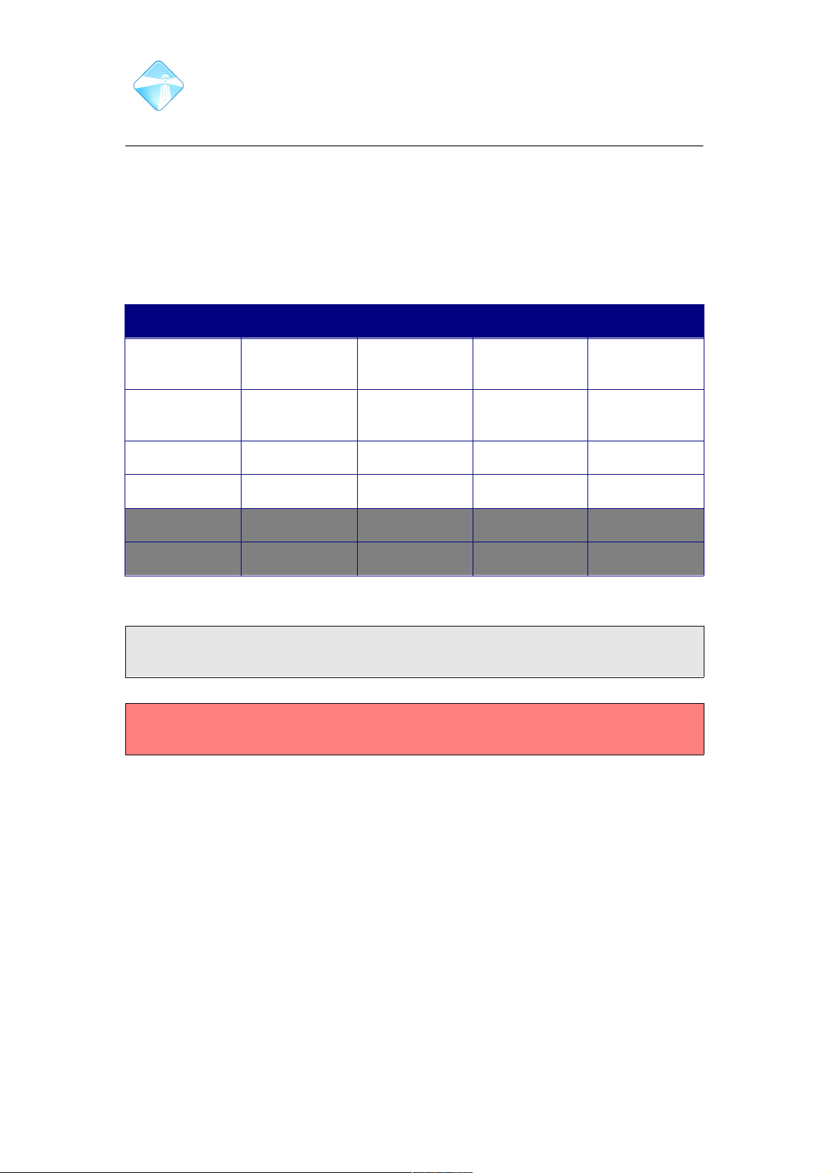
The Com.X units ship with 2 - 4 external ethernet ports labeled lan1, lan2 etc.
(enumerated from eth0 in the Operating System). Com.X1 and Com.X10 models
have an internal ethernet port (eth3), and certain Com.X5 models have an internal
port for DSL applications (wan). The ports are factory-configured as follows.
Interface Models DHCP? IP Netmask
lan1 / eth0 X1, X2, X5,
X10
DHCP Client - -
lan2 / eth1 X1, X2, X5,
X10
No 192.168.101.1 255.255.255.0
lan3 / eth2 X1, X5, X10 No 192.168.102.1 255.255.255.0
lan4 / eth3 X5 No 192.168.103.1 255.255.255.0
internal / eth3 X1, X10 No 192.168.103.1 255.255.255.0
wan X5 No - -
Table 1: Default network interface configuration
Note: Com.X5 systems utilize an internal PCI bus and offer external connection to
the lan4/eth3 network interface.
Warning: Changing the configuration of the internal eth3 interface may result in loss
of service on Com.X1/Com.X10.
2.1.2 Authentication
Web login has been pre-configured with the default administrator username 'admin'
and password 'admin'. It is advisable to change this password directly after
installation.
2.1.3 Remote web login
Once the unit has been powered on and started up, it can be accessed from a
Firefox, Internet Explorer or Chrome web browser with the URL set to the IP address
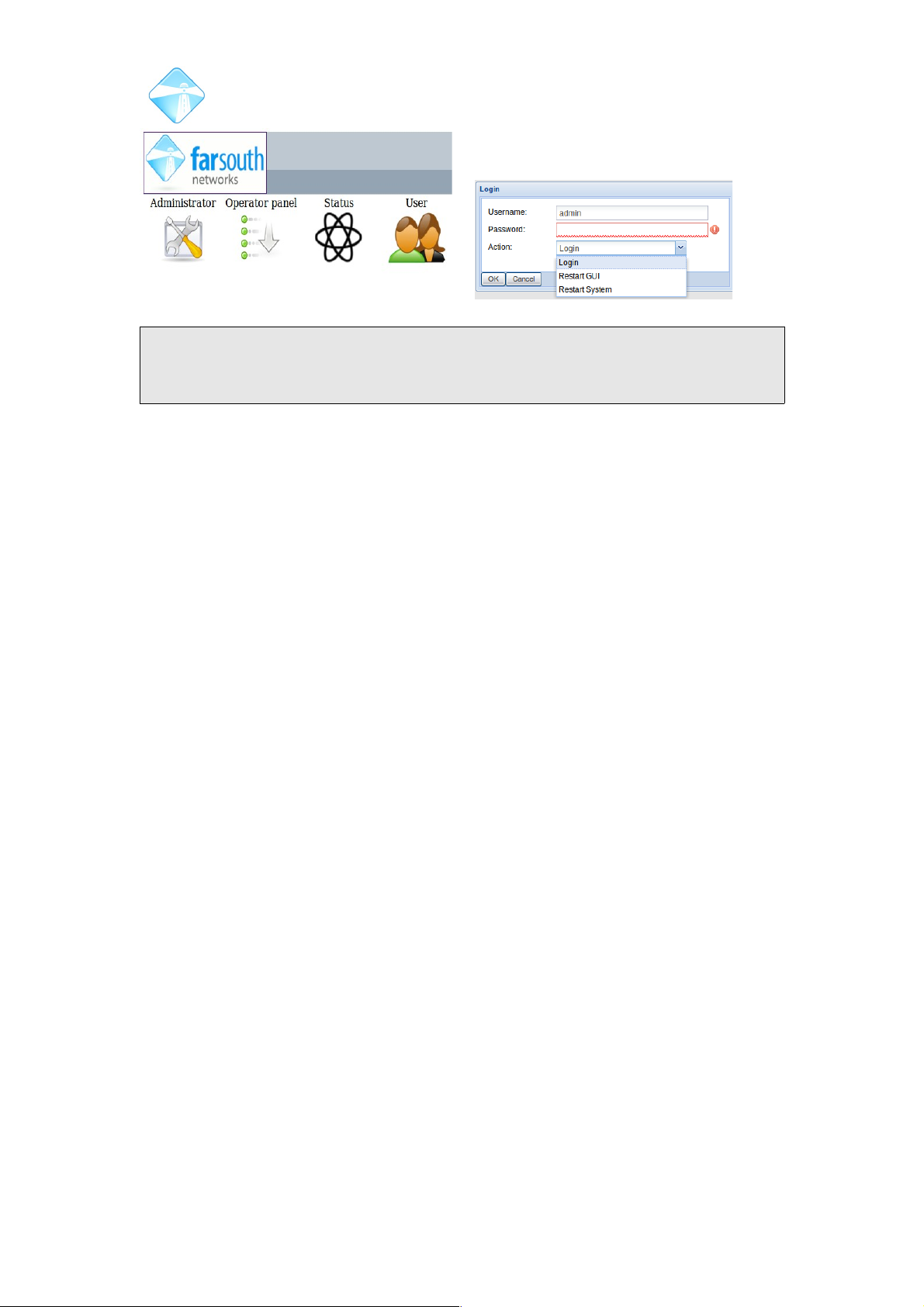
of the unit. Select the Administrator button to log in. Enter your username and
password and select 'Login' to authenticate. Please see section 2.1.8 for more detail
on changing the administrator's password.
©2010 – 2016 Far South Networks
Page 20
Com.X Administrator Guide
Page 20
Note: Should your GUI eventually time out rather than loading correctly, you can
now select to Restart the GUI and to restart the system directly from the web portal
log in.
2.1.4 Wanderweb Activation
Units featuring 1.4 software are compatible with the Wandwerweb cloud platform.
Wanderweb provides a cloud-based platfrom through which administration and user
features can be accessed.
User features include:
• a webRTC extension in your browser or mobile appplication, twinned with
your desktop extension.
• Instant messenger service to other Wanderweb users
• Remote access to company phonebooks
Admin features include:
• Remote access to the GUI and terminal of the unit, through Wanderweb.
• Device and service monitoring
• Service report/alert prioritisation
• Remote extension and user configuration through Wanderweb.
For more information or to sign up to Wanderweb contact your distributor or Far
South Networks. Configuration management
2.1.5 GUI layout
The Com.X GUI facilitates status monitoring and control of the unit and peripheral
devices via a set of menus accessible from the menu bar. After any changes have
been made to the configuration, these need to be reviewed and applied before they
take effect.
©2010 – 2016 Far South Networks
Figure 1: Com.X web portal
Figure 2: Remote web login
Page 21
Com.X Administrator Guide
Page 21
2.1.6 Configuration status
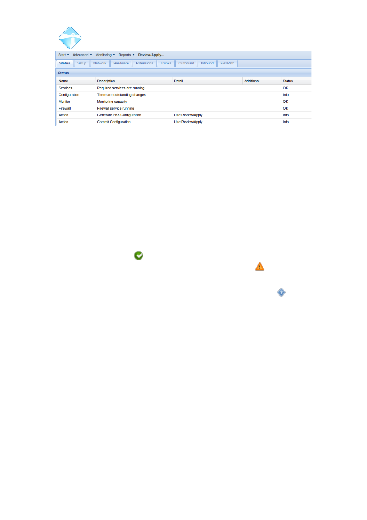
The current configuration status, indicating pending tasks and status alerts, can be
viewed from the configuration menu:
When the status on the Status tab is SYNCHRONIZED, the configuration is up to
date and synchronized with the underlying system configuration resources. If the
status is PENDING or MODIFIED, the Review/Apply button will be emphasized and
the administrator needs to review and apply the configuration using the Review/Apply
button in order to synchronize.
At the top right of the GUI a status icon indicates the over-all system status. If this
indicator is a green check , the system is synchronized and all services are
running. If the status indicator is an orange/yellow warning symbol , the
configuration requires audit and apply, or, the system is in error and requires
attention. Clicking the status indicator navigates to the Configuration status panel on
the GUI. The unknown indicator shows that system status is not available
(possibly still being acquired after restart or GUI login.)
See section 5.1 for further details on the GUI status page.
2.1.7 Applying and reverting a configuration
Select the Review/Apply button. A list of tasks to be applied will appear. Review the
task list and select Apply to proceed.
To revert changes and return to the configuration last applied, select the Revert
button.
To apply changes without disrupting service to users, select “Apply when no calls”.
The system will monitor the number of active calls, and if all calls clear, will initiate
apply. The system will remain pending Apply until all calls have terminated.
To continue configuring the system without applying, select Cancel.
During apply, individual task progress and success or failure is indicated. Once the
process has completed, a confirmation is displayed.
©2010 – 2016 Far South Networks
Figure 3: GUI layout and configuration status
Page 22
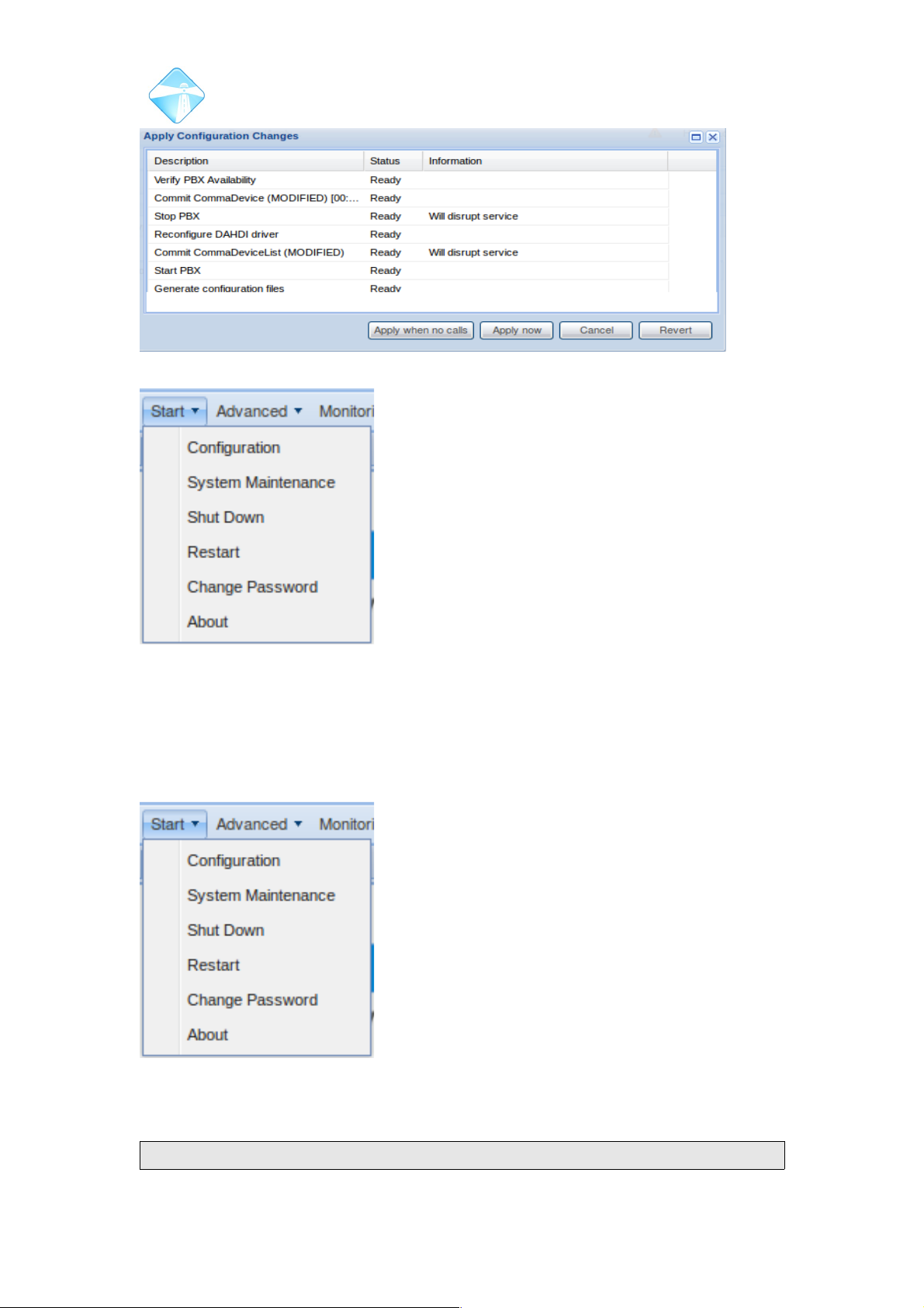
Com.X Administrator Guide
Page 22
Figure 4: Review / apply task list
2.1.8 Changing the default administrator's password
The password for the default administrative user (admin) can be changed by
selecting the “Change Password” option from the Start menu. Enter the existing
password, the new password and its confirmation and Accept to apply the change.
Note: changing the administrator's password on the GUI also changes the
©2010 – 2016 Far South Networks
Figure 5: Start menu options.
Figure 6: Start menu options.
Page 23
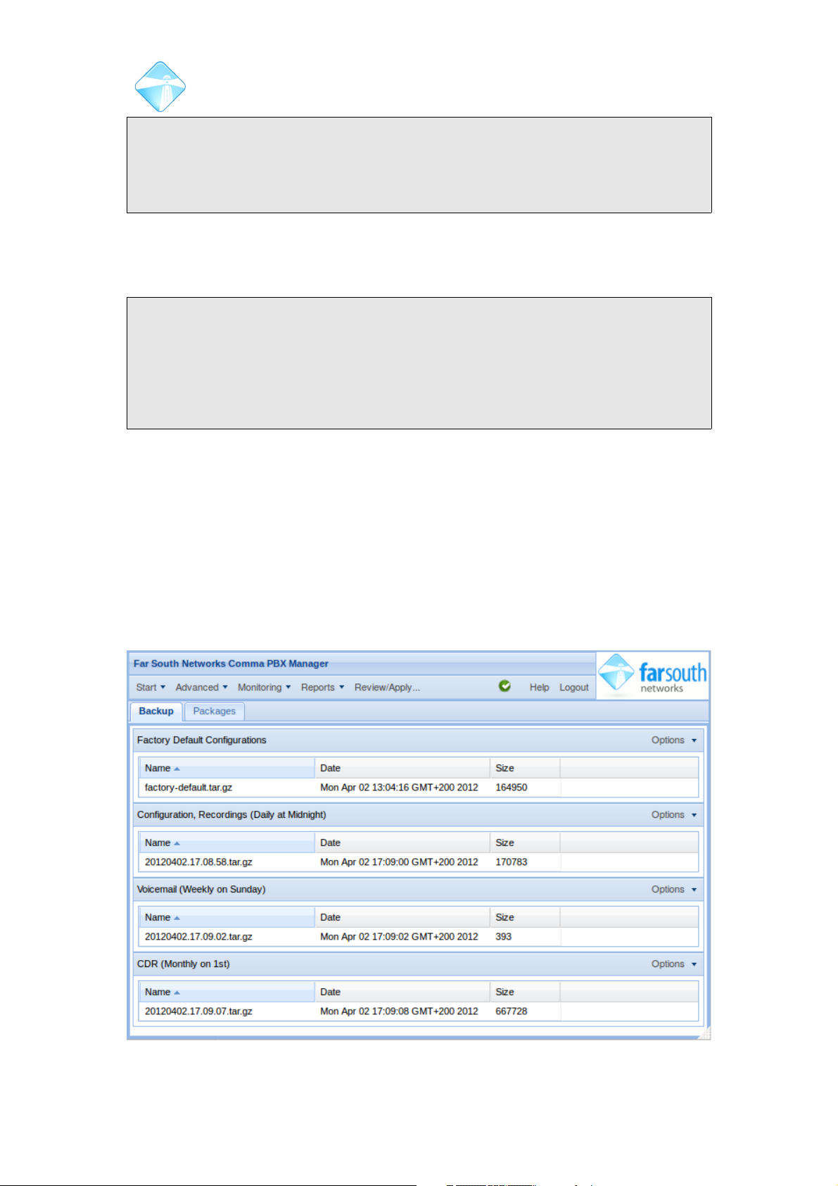
Com.X Administrator Guide
Page 23
underlying advanced FreePBX GUI's password accordingly.
Note: changing the administrator's password does not change the SSH login
password for the system, the ARI call monitor password or the MySQL database
password. Please see section 3.15 for more information on securing the system.
2.1.9 Rebooting and Shutting down
Select Start and then Restart or Shutdown (please wait 2 minutes before power
cycle).
Note: Any changes that have not been applied will be lost. When the system has
been shut down, it remains powered on but halted. Only a physical power cycle will
power it on again.
Note: Startup typically takes 2 – 3 minutes, but the system will check its hard disk
integrity every 20th start-up. This could delay start-up by a few minutes. If uncertain
of the system state, please connect a serial cable to determine the boot state.
2.2 System Maintenance
2.2.1 Backup and Restore
The Com.X configuration can be backed up to the unit's internal hard drive, or
downloaded to another machine. Backups can be scheduled daily, weekly and
monthly, and individual sections of the configuration can be configured for backup,
each with its own schedule. Immediate backups can also be initiated. Backups are
stored on the system in /var/lib/asterisk/backups/
From the Start menu, select System maintenance and then Backup. Please see
section 6.6 for more information regarding manual backup and restore.
©2010 – 2016 Far South Networks
Figure 7: System maintenance - backup
Page 24
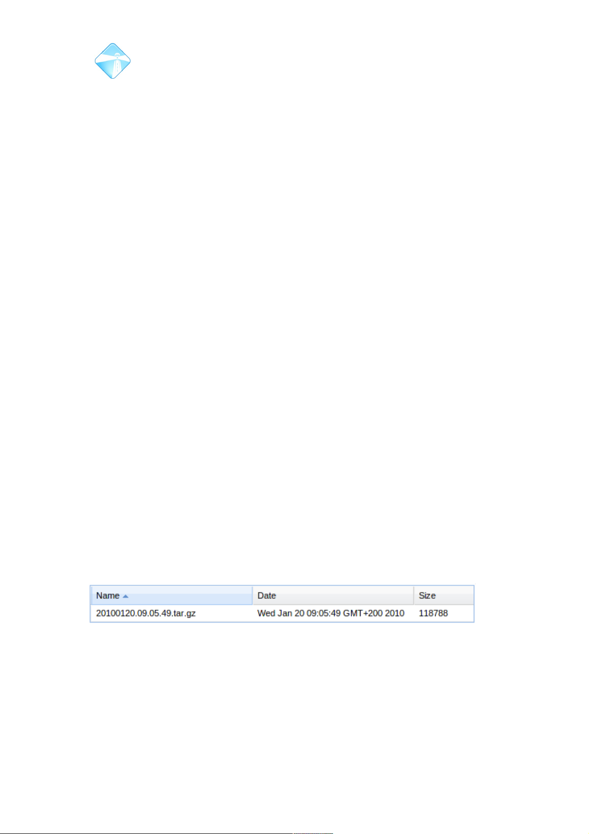
Com.X Administrator Guide
Page 24
2.2.1.1 Backup contents
The following selection of backup sets are provided for backup:
2.2.1.1.1 Factory default configurations
Com.X systems ship with a default factory configuration, which includes the default
configuration of telephony ports in the system. This configuration is reflected on
hardware the Hardware panel. Factory default configurations cannot be deleted from
the GUI, but can be stored offline and may also be uploaded to the system.
2.2.1.1.2 Configuration, Recordings
System configuration, including network, device, trunk, extension, voicemail,
inbound, outbound and FlexPath configurations, as well as all recordings present on
the system, including system recordings, auto attendant and music.
2.2.1.1.3 Voicemail
All user voice mailboxes with messages and the listened-to state of the messages.
This could result in a substantial archive.
2.2.1.1.4 CDR
Backs up the system's Call Data Record database.
2.2.1.1.5 Excluded from backup
The following items are excluded from backup and should be provided for by the
system installer, using scheduled scripts or other mechanisms:
• Custom FOP2 configuration (FOP2 configuration is generated by the Com.X
GUI on apply. Custom configurations are not backed up.)
• NFS configuration
• Mail relay configuration Third party module / service configuration (e.g. P$X,
FOP, Queue statistics, PPPoE, TNG, Man3000, device mount configurations,
etc)
• Static network routes
2.2.1.2 Immediate backup
To initiate an immediate backup, select “Backup now” from the Options menu for the
desired backup set. After successful completion, the backup archive will be listed
under the appropriate section.
2.2.1.3 Scheduled backup
To schedule a backup, select the Options menu for the desired backup set, select
“Schedule” and select the desired backup frequency. To remove a schedule, select
Manual Only.
©2010 – 2016 Far South Networks
Figure 8: The new backup is listed under the appropriate section.
Page 25
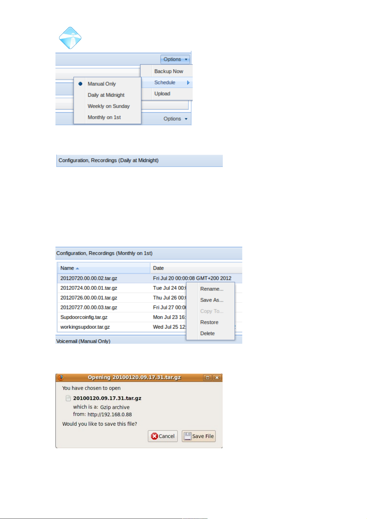
Com.X Administrator Guide
Page 25
The schedule setting is reflected in the backup set's title bar.
2.2.1.4 Managing existing backup archives
As scheduled backups complete and immediate backups are initiated, the existing
archives are listed under the appropriate sections on the backup panel. The most
recent backups appear at the bottom of each section. To sort by a particular column,
click on the column header.
Individual backup archives can be managed by right-clicking on the entries. To
download an archive to a local disk, select Save As and follow the browser prompts.
©2010 – 2016 Far South Networks
Figure 9: Backups can be scheduled to back
up the Com.X settings automatically.
Figure 10: The schedule (if configured) is displayed on the title bar.
Figure 11: Managing individual backup archives.
Figure 12: Save the backup archive to an external
location.
Page 26
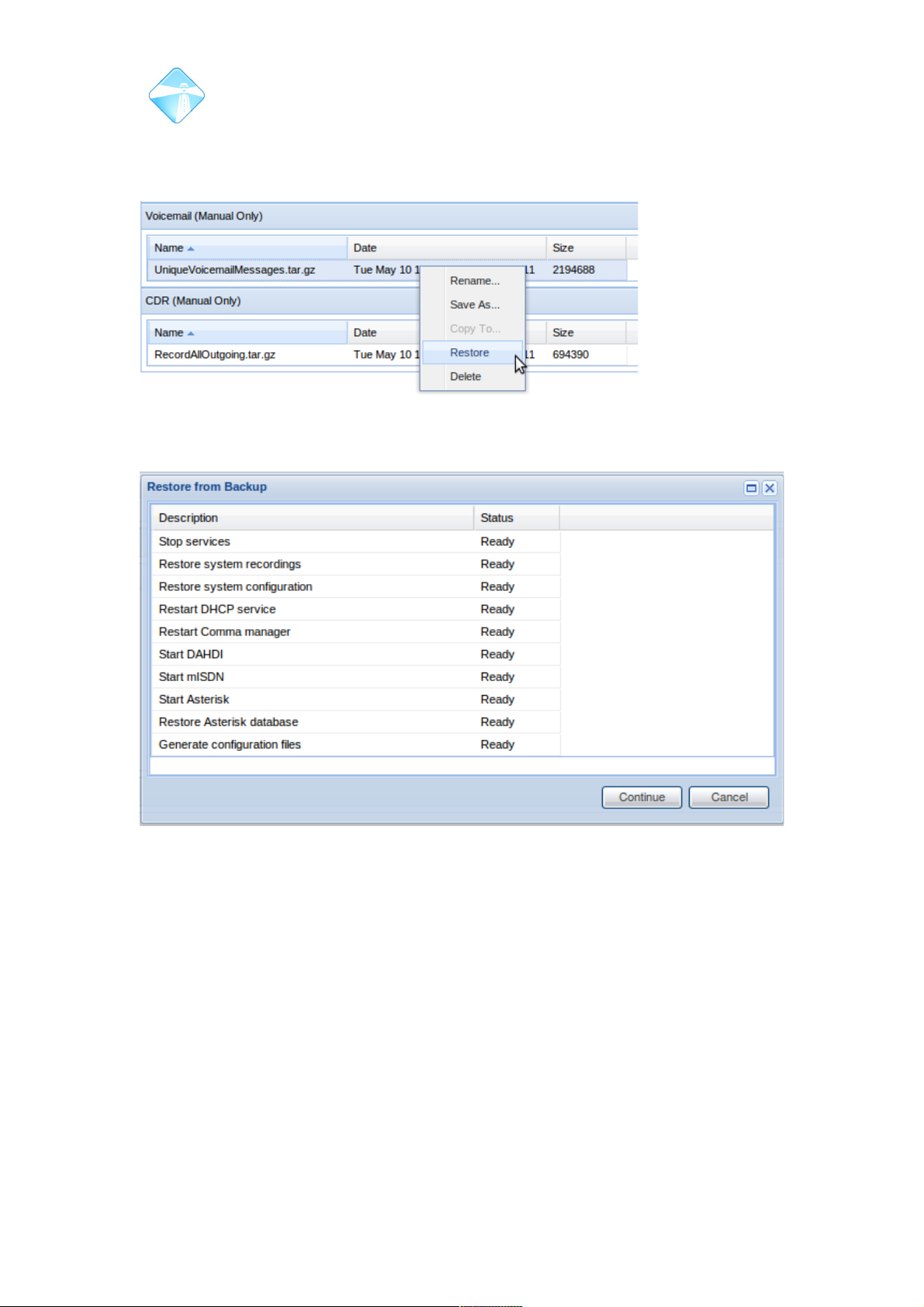
Com.X Administrator Guide
Page 26
2.2.1.5 Restoring an archive onto the same system
To restore from an existing archive, right-click the archive in the list and select
Restore.
The list of steps to be executed during the restore are displayed. Select Continue to
restore, or cancel.
Reboot the system once restore has completed (please see 2.1.9).
To restore from a data file saved at an external location, first upload the archive to the
Com.X and then follow the procedure above. Select “Upload” from the options menu
on the appropriate backup set in order to upload an archive.
2.2.1.6 Restoring an archive onto a replacement system
In case of hardware failure, it might be necessary to restore the configuration of a
system onto a replacement unit.
to restore from a data file saved at an external location, first upload the backup to the
Com.X.
Select “upload” in the options menu of the relevant section. Enter or browse to, the
location of the backup archive and submit.
©2010 – 2016 Far South Networks
Figure 13: Restore the selected backup.
Figure 14: Tasks to be executed are listed with an option to cancel.
Page 27
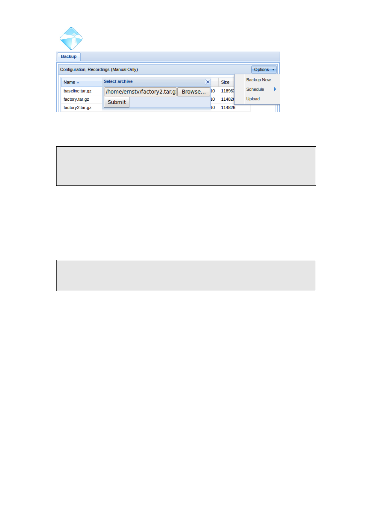
Com.X Administrator Guide
Page 27
Then follow the procedure in 2.2.1.5 to restore the backup onto the system.
Note: After a configuration has been restored, you will be required to apply the
changes. This gives the opportunity to change any settings (network configurations
in particular may need changing, to avoid loss of service) before they become active
on the system.
Once restored, select Start – Configuration and then select the Hardware panel. The
restored device should be listed, but the MAC address will not match that of the
device in the replacement unit. As a result some telephony spans may not be
available.
To update the restored configuration with the replacement device's MAC address,
edit the hardware entry (double-click or right-click-edit) and select the selection
button to the right of the MAC address field and select “Update from detected”.
Note: It is important to note that the telephony port configuration of the replacement
unit must match that of the system to be replaced. The restore process will only list
detected devices for which the port configurations match.
Select the appropriate detected device, accept and apply the changes. A system
restart may be required to ensure all telephony spans are working.
©2010 – 2016 Far South Networks
Figure 15: Submit the desired archive for upload.
Page 28
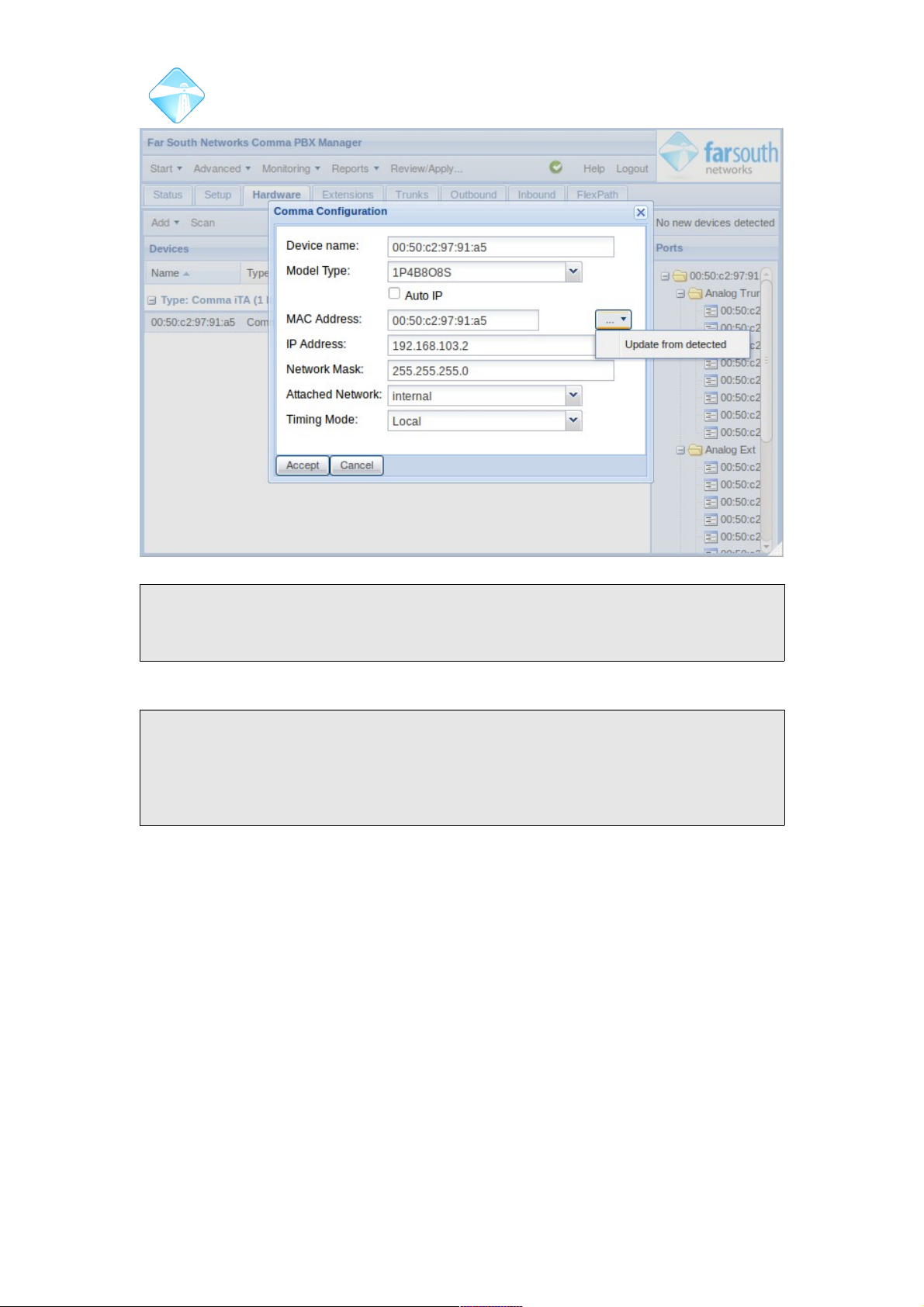
Com.X Administrator Guide
Page 28
Note: Updating of the MAC address is necessary only on iTA devices. Units that
contain only MPX telephony devices (such as a Com.X 5 with no external iTA's ) will
not require MAC addresses to be updated.
These archives contain the relevant licenses for Farsouth (gateway or PBX) and third
party software.
Note: If a configuration back up is made on a system featruing budget trunks, the
remaining minutes field is set to the minutes remaining on the system at the time the
back up is made. If this back up is then restored to the system, the trunk will be
created with the remaining minutes field already set. This field should be manually
reset after any configuration archive restoration.
2.2.2 Licensing
Licenses are used to enable functionality on 1.4 systems. Licenses are available for
full PBX functionality, gateway and PBX major release upgrades and for certain third
party installations, like ViBE (see section 2.2.4 for more information on ViBE
licensing) and FOP2 (see section 6.18 for further information on FOP2).
2.2.2.1 Adding a License
License archives of the form <serialnumber>_XXXXXXXXXXXXXXXXXXX.zip
obtained from Far South Networks are uploaded to the system via the GUI. These
archives contain the relevant licenses for Farsouth (gateway or PBX) and third party
software. These licenses will only work on the unit for which they are issued.
From the system maintenence page, select the packages tab, and then options,
licensing, and Add License.
©2010 – 2016 Far South Networks
Figure 16: Updating the MAC address of a replacement unit
Page 29
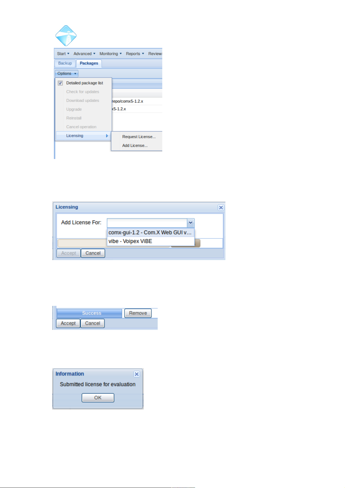
Com.X Administrator Guide
Page 29
This will allow you to upload a license from your computer. Select they type of
License you would like to add and then Browse your computer for the correct license
file.
As the license file is retrieved the status bar will turn blue. Accepting will upload the
selected file.
The .zip folder is then submitted for authentication. After which the GUI restarts.
©2010 – 2016 Far South Networks
Figure 17: Manage Licenses via the
GUI
Figure 18: Select the appropriate license type before
uploading the license.
Figure 19: File retrieved and ready for
upload.
Figure 20: Licenses submitted
for authentication
Page 30
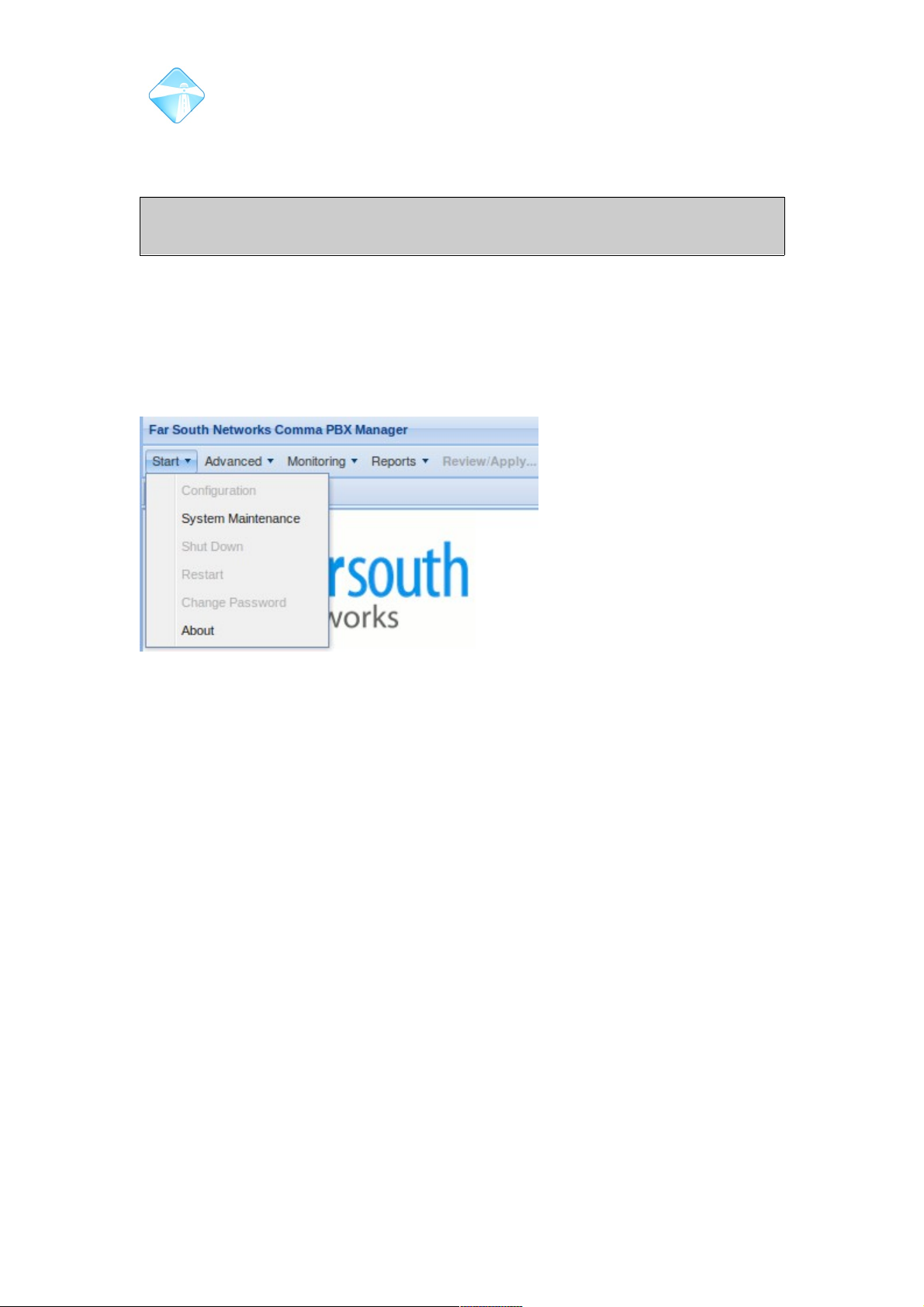
Com.X Administrator Guide
Page 30
After uploading a license to the Com.X, allow a few seconds for the GUI to update
and refresh. If the license is accepted the appropriate GUI functionality will be
available.
Note: It may be necessary to manually restart the GUI from the command line after
adding a license: sudo /etc/init.d/comma-gui restart
2.2.3 Unlicensed Functionality
Unlicensed functionality is presented as grey and is inaccessible in the GUI, as such,
the GUI of a Com.X gateway will show several greyed-out PBX configuration options.
This functionality can be remotely enabled by adding a Com.X PBX license, which
can be purchased from Far South Networks, through your distributor.
2.2.4 ViBE Licensing
In order to operate a ViBE enabled link or network a once-off license is required for
each ViBE-enabled CPE. To activate the ViBE application, this license needs to be
installed on the internal ViBE CPE of the Com.X.
ViBE licenses can be purchased through your Far South Networks distributor and are
uploaded to the GUI as in section 2.2.2.1.
Please refer to section 6.17 for further details on the ViBE application.
2.2.5 Updating the software
Com.X software updates are published from time to time on the Far South Networks
repository. The updates are freely available to licensed units with valid software
maintenance contracts.
2.2.5.1 Updating the PBX software
Each Com.X unit ships with the Far South Networks repository configured in
/etc/apt/sources.list:
The software packages on Com.X units need to be updated from time to time to
ensure optimal functinality and to incorporate new features.
Updates are released as a part of two top-level managed packages, namely the
comx-base and comx-gui packages, that can be updated from the Com.X GUI.
©2010 – 2016 Far South Networks
Figure 21: Only system maintenance options
available from the GUI of a system with no active
licenses.
Page 31
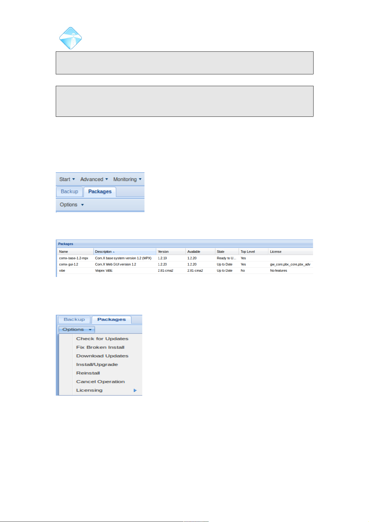
Com.X Administrator Guide
Page 31
Note: Units need to have internet access in order to retrieve update packages from
the Far South Networks repository.
Note: On Com.X5 units, the comx-base package is somewhat different to the
equivalent package for Com.X1, Com.X2 and Com.X10 units. As such the
corresponding package on Com.X5 builds is named comx-base-1.2-mpx.
2.2.5.1.1 Managing Packages from the GUI
The status of the two top-level packages is displayed on the Packages tab of the
System Maintenance page of the Com.X GUI.
Select Start, System Maintenance and then the Packages tab.
A list showing the com.x-base, comx-gui and vibe
packages, as well as their versions and status is displayed.
The State column provides information comparing the version of the installed
package to the version of the latest package available on the Far South Networks
repository.
2.2.5.2 Updating Packages
2.2.5.2.1 Check for updates
From the Packages tab of the System Maintenance page, select Check For Updates.
On this command, the Com.X connects to the repository and compares current
package versions to those available.
©2010 – 2016 Far South Networks
Figure 22: Select the
Packages tab
Figure 23: Managed packages listed with version and status.
Figure 24: Options available for managing packages.
Page 32
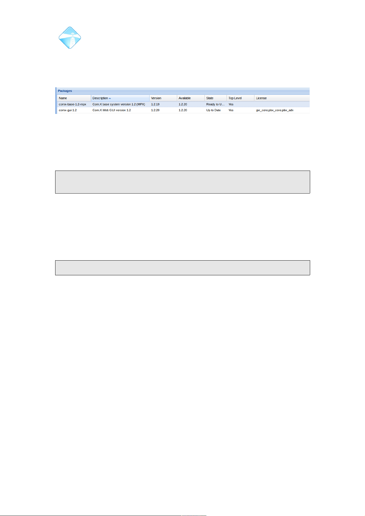
Com.X Administrator Guide
Page 32
2.2.5.2.2 Download Updates
To download updates for a particular package, or multiple packages, select the
package in the package list, or select multiple packages using Ctrl-click. A selected
package is distinguished by a blue highlight.
With one or more packages selected, click Options and then Download updates.
This will pull the latest packages from the Far South Networks repository and store
them on the Com.X, however it will not install the updates until requested to do so.
This allows updates to be retrieved immediately, but installed at a convenient time,
when service can be interrupted.
Note: If no packages are selected, the GUI will ask if you would like to download
updates for the two top-level packages, comx-base and comx-gui
2.2.5.2.3 Install/Upgrade
Select individual packages or multiple packages as in section 2.2.5.2.2 and then click
on the Install/Upgrade option in the Options list. This will install any updates to the
selected package that have been downloaded but not installed. If there are no
dowloaded updates, then the Com.X will download and install the updated packages
from the Far South Networks repository.
Note: Installation of updates may incur a brief loss of service.
2.2.6 Upgrading a 1.3 system to 1.4
Com.X units featuring 1.3 software can be upgraded to use 1.4 software. Please
contact your Far South Networks distributor for further details or pricing information.
©2010 – 2016 Far South Networks
Figure 25: Individual packages can be selected.
Page 33

Com.X Administrator Guide
Page 33
3 Commissioning the unit
3.1 Global settings
A range of global settings are available for configuration,
Double-click a field to edit the field and enter required information.
©2010 – 2016 Far South Networks
Page 34
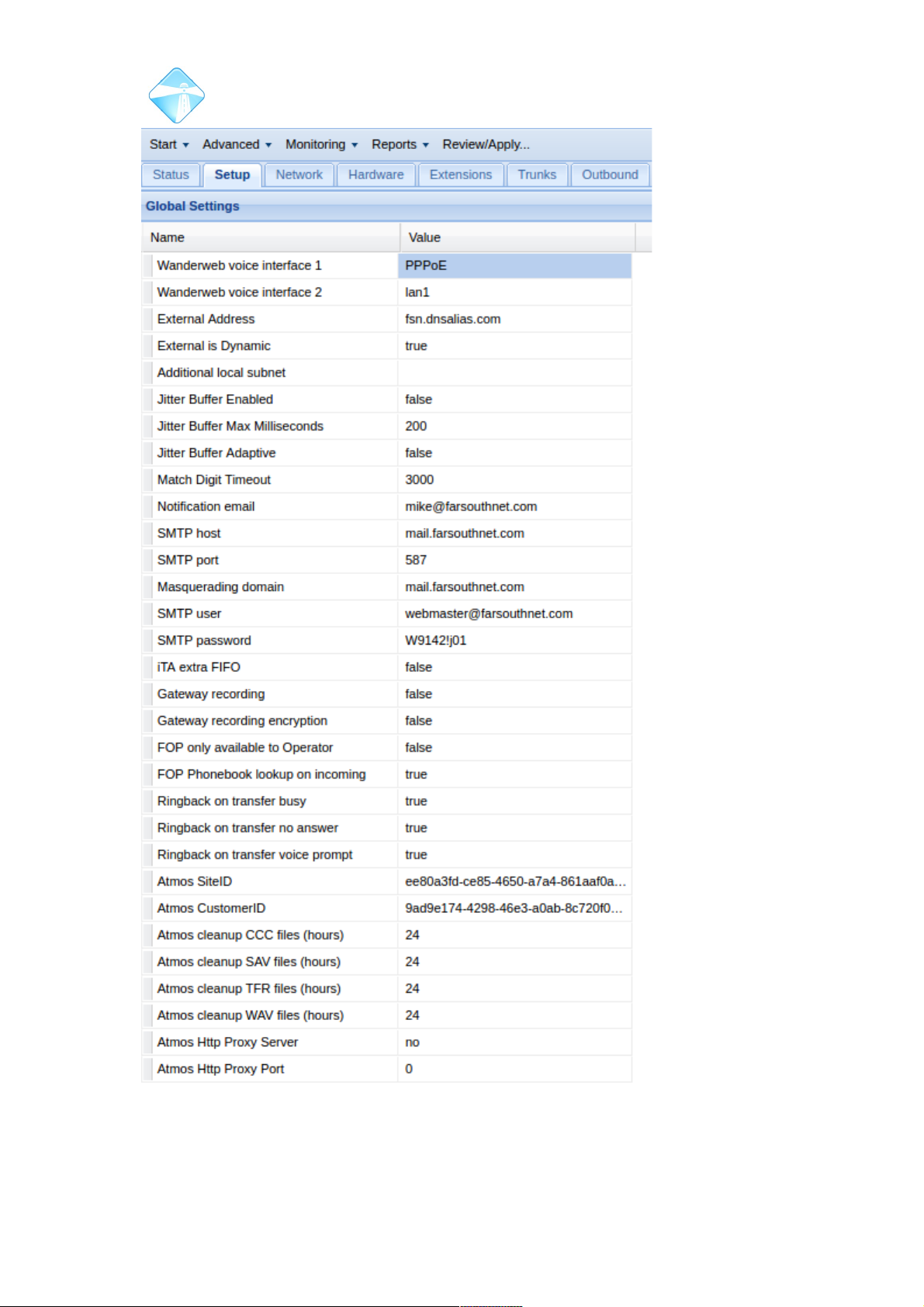
Com.X Administrator Guide
Page 34
©2010 – 2016 Far South Networks
Figure 26: Global Settings
Page 35

Com.X Administrator Guide
Page 35
Field Content
Wanderweb voice
interface 1
The primary interface through which the unit reaches
www.wanderweb.net through the internet.
Wanderweb voice
interface 2
The secondary interface through which the unit reaches
www.wanderweb.net through the internet.
External Address If specified, outgoing SIP packets will include this address as
the source address of the SIP packets.
External is
Dynamic
When true, indicates that the SIP source host specified should
be treated as a dynamic host. This informs the remote peer to
resolve the address of the host for each dialog, in case the
address has changed.
Additional local
subnet
The subnet (IP and subnet mask in the form A.B.C.D/E.F.G.H)
for any additional local subnet. Traffic on this subnet will be
treated as local by the Com.X for SIP purposes.
Jitter Buffer
Enabled
When enabled, a SIP jitter buffer will be instantiated for each
SIP call.
Jitter Buffer Max
Milliseconds
Indicates the maximum number of milliseconds that the jitter
buffer is allowed to buffer media before streaming out.
Jitter Buffer
Adaptive
When enabled, uses an adaptive buffering algorithm that
adjusts to the media stream conditions. When disabled, the jitter
buffer length is fixed to the maximum value specified.
Match Digit
Timeout
The timeout in milliseconds after which, if no additional digit is
pressed, the dialed digit series is deemed complete and the call
is attempted.
Notification email Email address to which to send system notifications .
SMTP host The mail relay server to use when sending emails (including
notification emails and voicemail to email.)
Please see section 6.3 for a detailed discussion on email
services.
SMTP port SMTP host network port, default is 25
Masquerading
domain
The domain to masquerade from when sending emails.
SMTP user SMTP authentication user to use for sending email via the
SMTP host
SMTP password SMTP authentication password
iTA extra FIFO Provides additional receive FIFO buffers (4ms instead of 2ms)
for analogue and PRI channels on attached iTAs in case of
©2010 – 2016 Far South Networks
Page 36

Com.X Administrator Guide
Page 36
Field Content
network slips
Gateway
recording
If enabled, all calls on all trunks via the Com.X will be recorded.
Please see section 3.13.5 for a detailed discussion on gateway
recording.
Gateway
recording
encryption
If enabled, all calls on all trunks recorded will be encrypted
using the Com.X system's unique hardware key. Recordings
can only be decrypted on the same system, or using the
system's unique hardware key.
FOP only
available to
Operator
If set to true, this will restrict access to the Flash operator panel
to the operator extension set in the general settings page of the
advanced menu. Please see Section 6.18 for more detail on the
operator panel.
Ringback on
transfer busy
Enabled by default. If enabled, calls that are transferred to a
busy extension will ring back to the transferring
extensionRingback on transfer no answer
Ringback on
transfer no answer
Enabled by default. If enabled, calls that are transferred to an
extension and then unanswered, will ring back to the
transferring extension.
Ringback on
transfer voice
prompt
Enabled by default. If enabled a caller will hear a short
“extension unavailble, one moment please” message before a
call rings back to the transferring extension.
Table 2: Global settings
3.2 Network configuration
Configuration of all ethernet LAN and Wan ports is possible through the Network tab
of the Comma GUI. This module allows further control of router and firewall settings,
including configurations of zones on a port-by-port basis, general firewall policies,
and individual rules, providing exceptions to the configured policies.
3.2.1 Connections
The connections page allows for configuration of some global networking
parameters.
Double-click a field to edit the field and enter required information.
©2010 – 2016 Far South Networks
Page 37
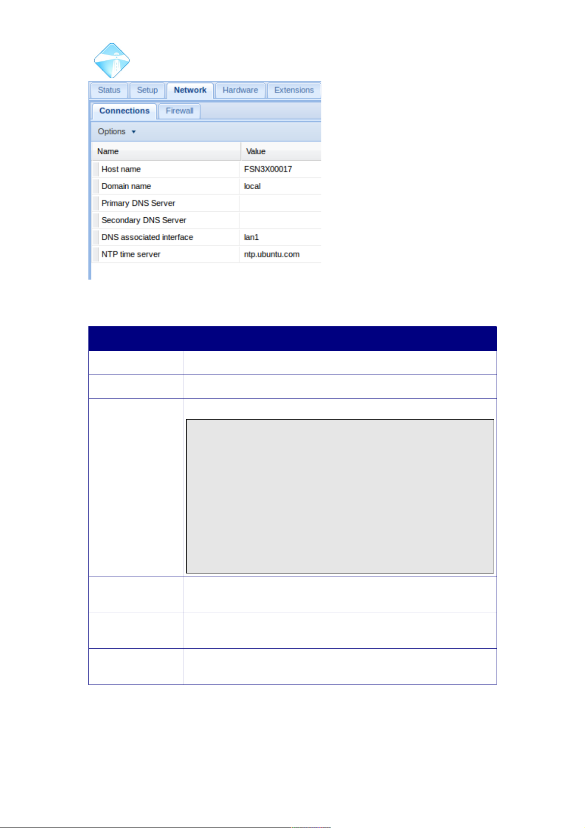
Com.X Administrator Guide
Page 37
Figure 27: Options available for global network
Field Content
Host Name The host name assigned to the Com.X.
Domain The system domain name. Use 'local' to indicate a local domain.
Primary DNS
Server
The system's primary Domain Name resolution Server
Note: the Com.X uses an open-source, synchronous DNS
lookup library. As a result, the Com.X makes use of a DNS
proxy to facilitate DNS lookups. If the primary DNS is
configured to an IP address outside the LAN (i.e. outside of the
network gateway router) and this DNS server or network
connectivity to the DNS server should become unavailable, the
Com.X and the DNS cache might both block on DNS lookup,
resulting in loss of SIP registration and general call failures.
Always configure the primary DNS as the LAN gateway router,
and the secondary DNS as an external DNS server if so
required.
Secondary DNS
Server
The system's secondary Domain Name resolution Server
DNS Associated
Interface
The interface through which the Com.X expects communication
from the DNS server.
NTP Time Server The NTP server the Com.X should refer to for time
synchronization in the NTP hierarchy.
©2010 – 2016 Far South Networks
configurations.
Page 38
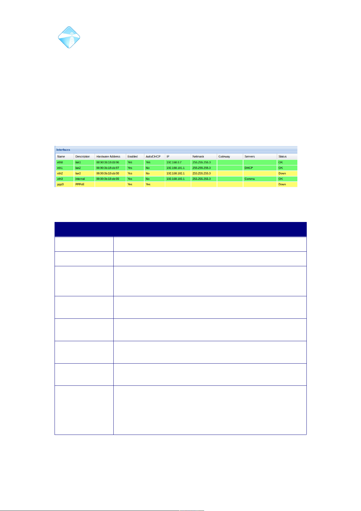
Com.X Administrator Guide
Page 38
3.2.2 Ethernet Interface Configuration
The Com.X GUI provides functionality to configure all ethernet interfaces, as well as
provision of DHCP IP allocation for IP phones and booting of Comma iTA devices.
The Com.X unit can serve both DHCP and Comma addresses simultaneously,
provided the IP ranges do not overlap.
3.2.2.1 Listing ethernet interfaces
To access the list of network interface configurations, select Configuration from the
Start menu and then select the Network panel and the “Interfaces” section.
Interfaces are coloured coded, with active, healthy ports indicated by green
highlighting, and yellow highlights indicating a port is in a warning or down status.
3.2.2.2 Configuring an Interface
Double-click an ethernet interface to configure the following fields:
Field Content
Name Operating System allocated interface name
Description A description for the interface
DHCP Client Determines whether the unit will try and obtain its IP
configuration from a DHCP server. If not selected, the fields
below need to be configured
Enabled By default each port is enabled. Unselecting this option will
disable the port for all functionality.
IP Address An IP address unique to the network. Auto-assigned if DHCP
Client is enabled.
Network Mask The network mask to use on the network. Auto-assigned if
DHCP Client is enabled.
Gateway The routing gateway for this interface. Auto-assigned if DHCP
Client is enabled.
Default Metric The metric of a network route is a property used by a routing
protocol to determine whether one particular route should be
chosen over another.
In conflicting cases, traffic will be directed towards the gateway
containing the lowest value metric.
©2010 – 2016 Far South Networks
Figure 28: Interface list, status is boldly indicated by colour highlighting.
Page 39
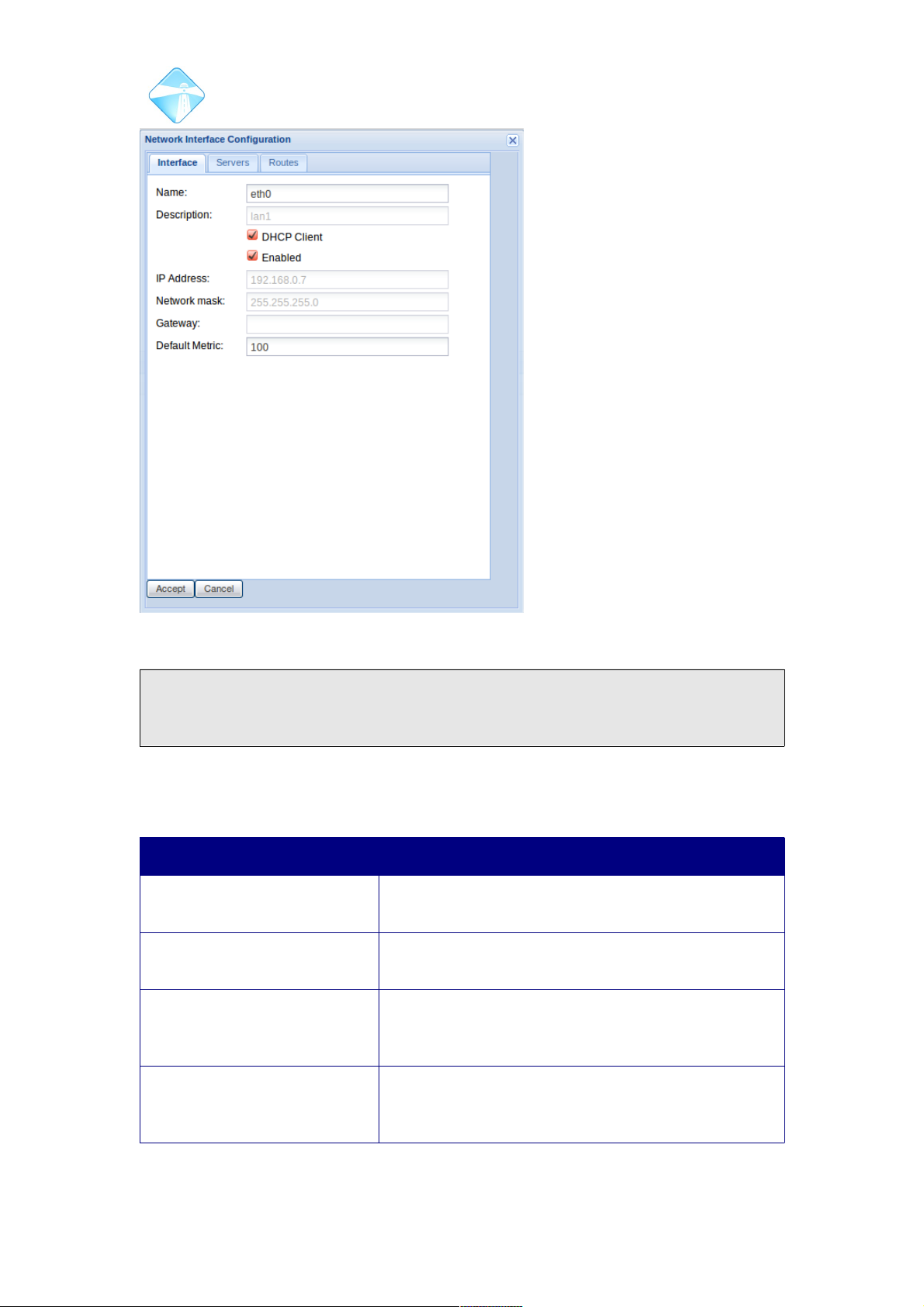
Com.X Administrator Guide
Page 39
Apply the configuration.
Note:After applying network configuration changes, the unit needs to be rebooted
or the networking service restarted before the changes become active in the
configuration.
3.2.2.3 Providing DHCP Server IP allocation to clients
Double-click an ethernet interface and select the Servers tab.
Field Content
DHCP Start Address The start address for the range of IP addresses from
which new DHCP requests should be served
DHCP End Address The end address for the range of IP addresses from
which new DHCP requests should be served
DHCP Router Address The address of the IP router / gateway to be used by
the device requesting IP configuration, normally the
same as the Com.X address on this interface.
DHCP DNS Server The primary DNS address to be configured on the
device requesting IP configuration, may be left
blank.
©2010 – 2016 Far South Networks
Figure 29: Ethernet LAN port configuration options.
Page 40
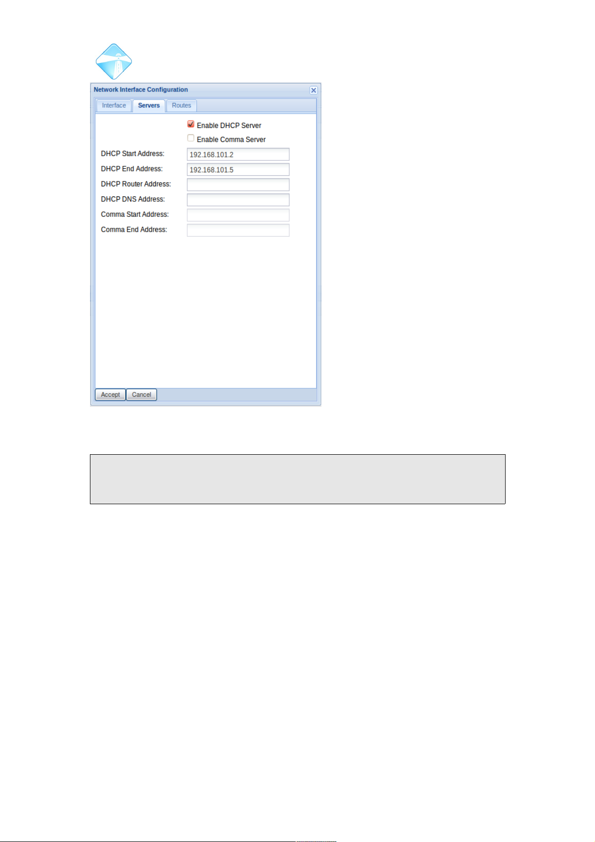
Com.X Administrator Guide
Page 40
Apply the configuration.
Note: When applying network configuration changes, the unit automatically restarts
the affected network interface(s). NB. If the interface used for GUI access is
reconfigured, GUI access may be affected.
©2010 – 2016 Far South Networks
Figure 30: DHCP and Comma server
configuration options.
Page 41
Com.X Administrator Guide
Page 41
3.2.2.4 Providing Comma iTA boot services
Double-click an ethernet interface and select the Servers tab.
Field Content
Comma Start Address The start address for the range of IP
addresses to allocate to new Comma
units. Once a unit has been assigned an
IP, the system will remember this
assignment, across restarts, and will
always reserve the IP for that unit. The IP
will no longer be served to future
commas.
Comma End Address The end address for the range of IP
addresses to allocate to new Comma
units.
Apply the configuration.
Note: On Com.X 1 and Com.X10 units, the eth3 interface is the internal ethernet
bus serving the Com.X Media processor card and should not changed from its
factory configuration.
©2010 – 2016 Far South Networks
Page 42
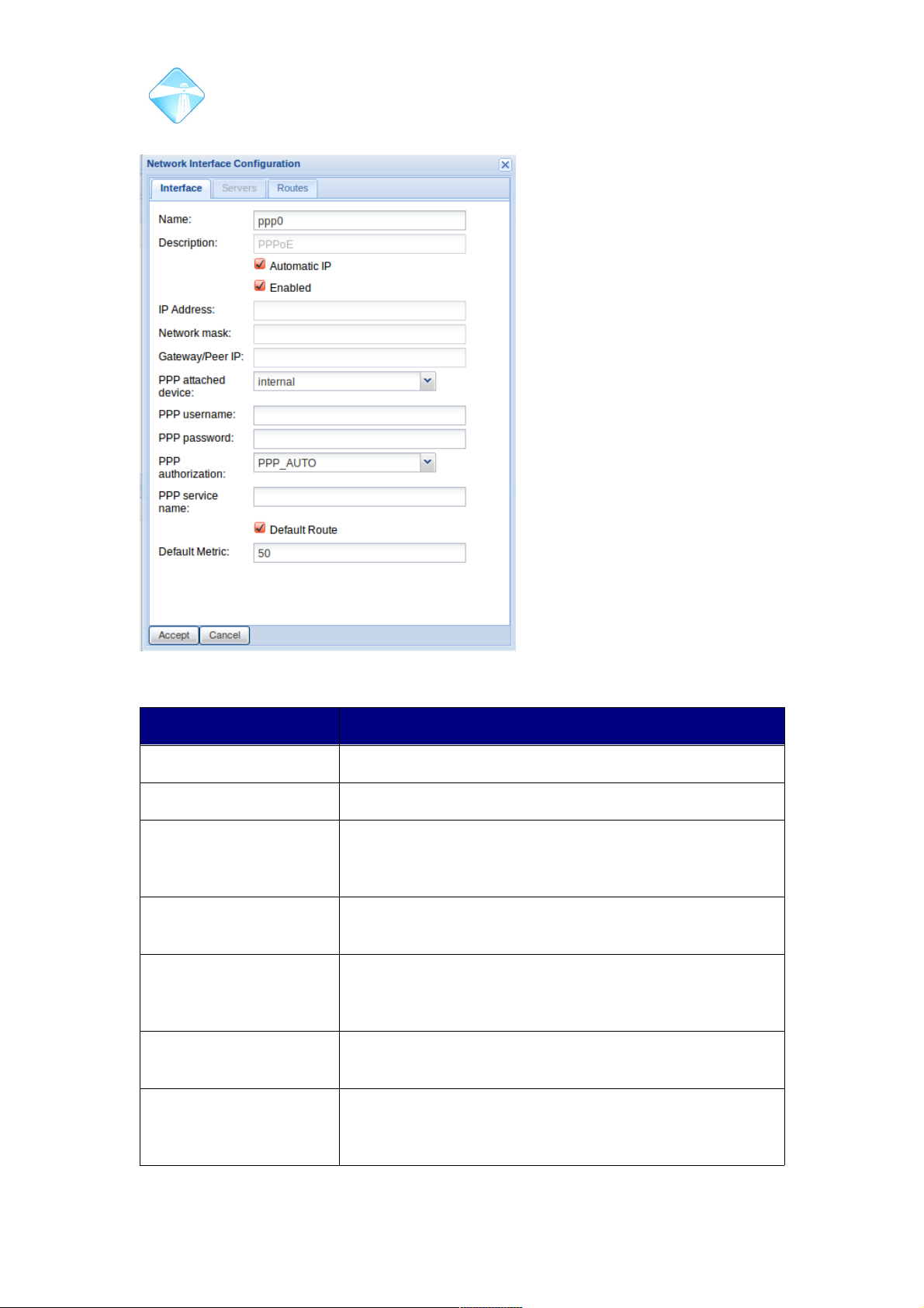
Com.X Administrator Guide
Page 42
3.2.3 Configuration of PPPoE Interfaces
Field Content
Name A suitable name for the virtual interface.
Description A description of the interface, marking it as PPPoE.
Automatic IP If enabled, the interface will attempt to dynamically
receive an IP address via IPCP. If left unchecked, a static
IP address can be configured.
Enabled By default the interface is enabled. Unchecking this
option will disable the interface for all functionality.
IP Address If Automatic IP is disabled, a static IP address can be
configured in this field. If Automatic IP is enabled then
this field can not be edited from the Gui.
Network Mask The network mask to use on the network. Auto-assigned
if DHCP Client is enabled.
Gateway Peer IP The IP address of the bridge mode router handling
PPPoE traffic. This could be an internal router (on select
Com.X5 units,) or another router on the local network.
©2010 – 2016 Far South Networks
Figure 31: PPPoE interface configuration options.
Page 43
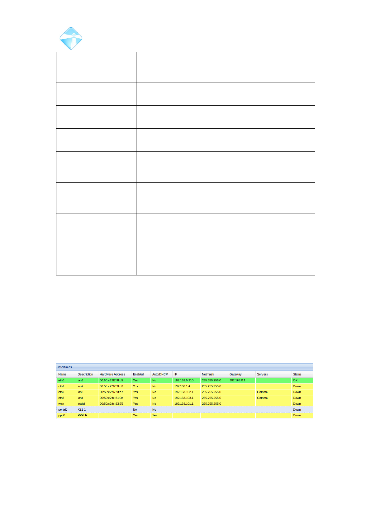
Com.X Administrator Guide
Page 43
PPP Attached Device The port through which the router can be reached. This
could be a Lan port on the Com.X or the internal dsl
router on select Com.X5 units.
PPP Username The username of with which to authenticate with your
service provider.
PPP Password The password associated with your username, used to
authenticate with your service provider.
PPP Authorization The authorization method used to authenticate your
account with your service provider.
PPP Service name This field should be left blank, unless your service
provider has requested that your configure your service
with a specific name.
Default Route If enabled, the PPPoE interface will be configured as the
default route for any IP traffic to an address matching no
other configured route.
Default Metric The metric of a network route is a property used by a
routing protocol to determine whether one particular route
should be chosen over another.
In conflicting cases, traffic will be directed towards the
gateway containing the lowest value metric.
3.2.4 X.21 Interface configuration
If the Com.X is equipped with an X.21 serial interface (typically for connection to
leased line or frame relay services), the interface is listed as serial0 (X21-1) in the
Interfaces list.
The Com.X X.21 interface is always DTE on the physical layer (although it may act
as protocol DCE in Frame Relay mode). Therefore, the clock and thus the data rate
of the interface is provided by the DCE equipment connected to the X.21 interface,
typically an NTU.
As with other network interfaces, the interface configuration may be edited by doubleclicking the list entry. The availability of the different fields will depend on the Serial
Protocol chosen.
©2010 – 2016 Far South Networks
Figure 32: Interface list including serial0, the X21 interface
Page 44
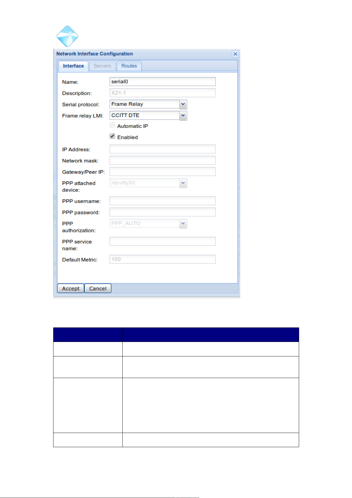
Com.X Administrator Guide
Page 44
The fields are described in the table below. Note that only PPP mode supports
Automatic IP configuration.
Field Contents
Name (not editable) serial0
Description (not
editable)
X21-1
Serial Protocol IP/HDLC – Raw IP in HDLC encapsulation
Cisco HDLC – Cisco compatible IP HDLC encapsulation
Frame Relay – ANSI/CCITT (ITU) compatible frame relay
encapsulation
PPP – Point-to-Point Protocol
Frame relay LMI (Only enabled when Serial Protocol is Frame Relay) – Local
©2010 – 2016 Far South Networks
Figure 33: X21 interface configuration
Page 45

Com.X Administrator Guide
Page 45
Management Interface protocol selection. Valid values are:
None
ANSI DTE
ANSI DCE
CCITT DTE
CCITT DCE
Automatic IP (only valid for PPP mode) – obtain IP address automatically
from the PPP peer
Enabled Interface enabled/disabled at startup
IP Address (except when Frame Relay or Automatic IP enabled) – IP
address of this interface
Network Mask (except when Frame Relay or PPP enabled) – Network
mask of this interface
Gateway/Peer IP (optional, not enabled when Frame Relay or PPP enabled)
– Peer IP for point-to-point links, or gateway for multipoint
PPP attached device
(not editable)
(only valid for PPP mode) /dev/ttyX0
PPP username (only valid for PPP mode) PAP/CHAP username
PPP password (only valid for PPP mode) PAP/CHAP password
PPP authorization Method of PPP authorization:
PPP_NONE – don't use PAP/CHAP
PPP_AUTO – use PAP or CHAP as required
PPP_PAP – use PAP only
PPP_CHAP – use CHAP only
PPP service name (optional) PPP provider's service name, normally left blank
Default metric The metric of a network route is a property used by a
routing protocol to determine whether one particular route
should be chosen over another. In conflicting cases, traffic
will be directed towards the gateway containing the lowest
value metric.
3.2.4.1 Frame Relay PVC Configuration
If the X.21 interface is configured for Frame Relay protocol, it is possible to add
multiple PVCs (Permanent Virtual Circuits), which themselves are separate network
interfaces with the usual configuration options. The list below shows a PVC interface
entry.
©2010 – 2016 Far South Networks
Page 46
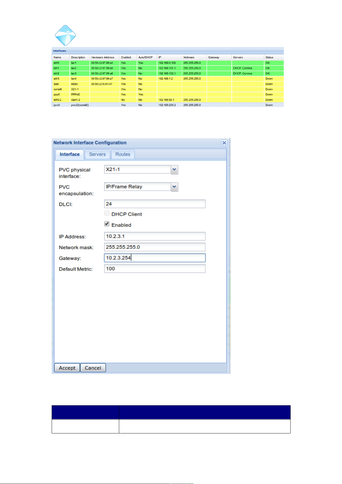
Com.X Administrator Guide
Page 46
PVCs are added by selecting Options → New PVC... The screenshot below shows
the configuration of a new PVC.
The fields are described in the table below.
Field Contents
PVC physical interface X21-1
©2010 – 2016 Far South Networks
Figure 34: PVC interface shown in interface list
Figure 35: X21 PVC device configuration
Page 47
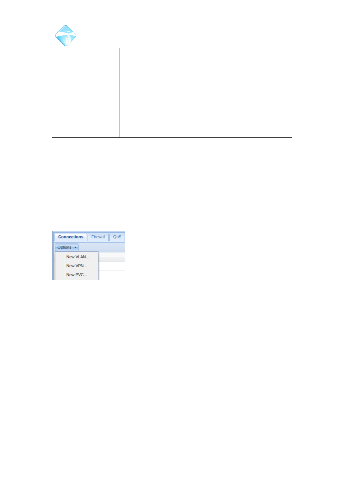
Com.X Administrator Guide
Page 47
PVC encapsulation IP/Frame Relay – Raw IP is encapsulated in the PVC frame
Ethernet/Frame Relay – IP over Ethernet is encapsulated in
the PVC frame
DLCI Data Link Connection Identifier – number from 1 to 1023
(normally in the range 16 to 991) that uniquely identifies this
PVC from others sharing the physical link
IP Address, Network
mask, Gateway,
Default metric
Same as for other interfaces
To edit a PVC, double-click its interface entry as usual. To delete a PVC, right-click
on the interface entry and select the Delete option in the menu.
3.2.5 Creating Virtual ports for VLAN and PVC
Virtual ports can be configured from the GUI, to connect to VLAN and PVC networks.
3.2.5.1 VLAN
To create a new virtual port on a Vlan network, navigate to the Connections page,
under the Network tab of the GUI. Then select New Vlan.
©2010 – 2016 Far South Networks
Figure 36: VLAN, VPN and
PVC port creation.
Page 48
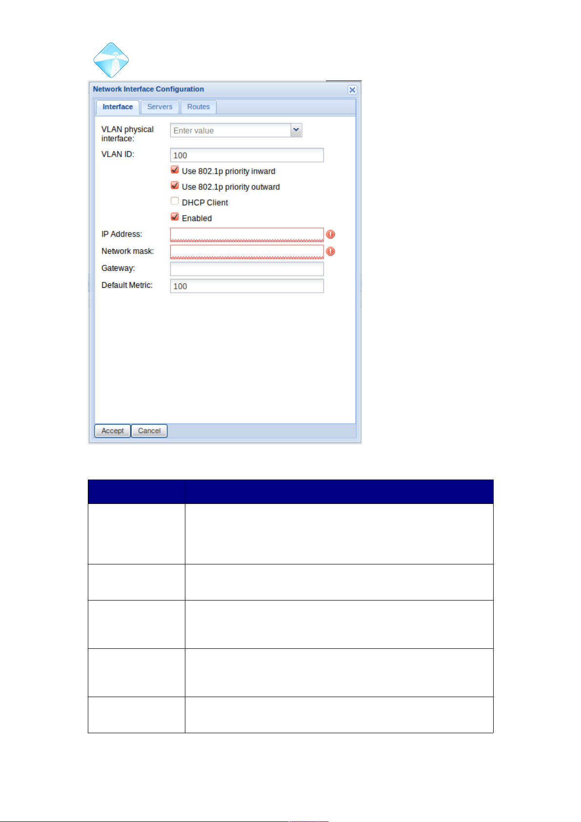
Com.X Administrator Guide
Page 48
Field Contents
VLAN Physical
Interface
The actual physical LAN interface through which this virtual port
connects to the rest of the virtual network. This could be any of
the LAN ports, or the internal dsl router on certain Com.X5
models.
VLAN ID A numerical identifier for the VLAN. Integer values from 1 to
4095 are valid VLAN identifiers.
Use 802.1p priority
inward
If checked (the default), the VLAN priority field on the incoming
packet will be mapped to a network queue priority on the
Com.X device
Use 802.1p priority
outward
If checked (the default), the QoS priority setting of the traffic
source will be set in the VLAN priority field of the outgoing
packets
DHCP Client If checked, this virtual port will receive an IP address from a
DHCP server elsewhere on the VLAN.
©2010 – 2016 Far South Networks
Figure 37: VLAN Configuration Options
Page 49

Com.X Administrator Guide
Page 49
Enabled By default the port is enabled. Disabling the port prevents all
functionality and will delete any associated IP routes. Reenabling the port will recreate associated IP routes.
IP Address If the interface is not configured as a DHCP client, a static IP
address can be configured in this field. If the interface is a
DHCP client, then this field can be read, but not edited from the
GUI.
Network Mask A network mask can be manually configured along with a static
IP address. If the interface is configured as a DHCP client, this
field will be populated in the DHCP negotiation process and can
be read, but not edited from the GUI.
Gateway The routing gateway for this interface. Auto-assigned if DHCP
Client is enabled.
Default Metric Sets the default metric value of routes utilizing this interface.
In conflicting cases, traffic will be directed through the route
containing the lowest value metric.
VLAN ports can be configured to act as DHCP and Comma servers , as in section
3.2.2.3 . Individual and specific IP routes can be associated to the VLAN interface in
a similar was as described in section 3.2.2.2.
©2010 – 2016 Far South Networks
Page 50
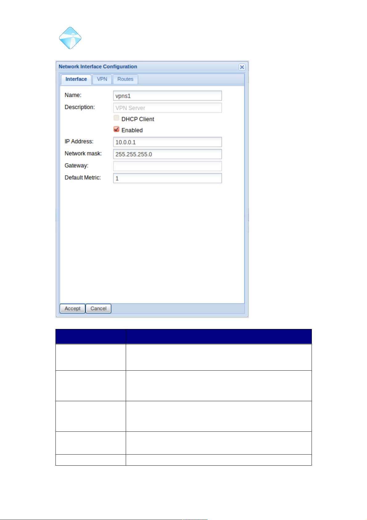
Com.X Administrator Guide
Page 50
3.2.5.2 VPN Interface
Field Contents
Name vpns1 – VPN server interface
vpncX – VPN client interfaces (X=1,2,3...)
Description Describes the type of VPN interface, automatically
configured to either VPN Server or VPN Client with a
number index.
DHCP Client Read only. Not applicable to VPN. A VPN server always has
a fixed IP address, whilst a VPN client always receives its IP
address from the remote server.
Enabled Optional setting to enabled or diasble the interface.
Disabling the interface will remove all associated ip routes.
IP Address The IP address of the VPN interface.Configurable only for
©2010 – 2016 Far South Networks
Figure 38: VPN interface configuration page.
Page 51
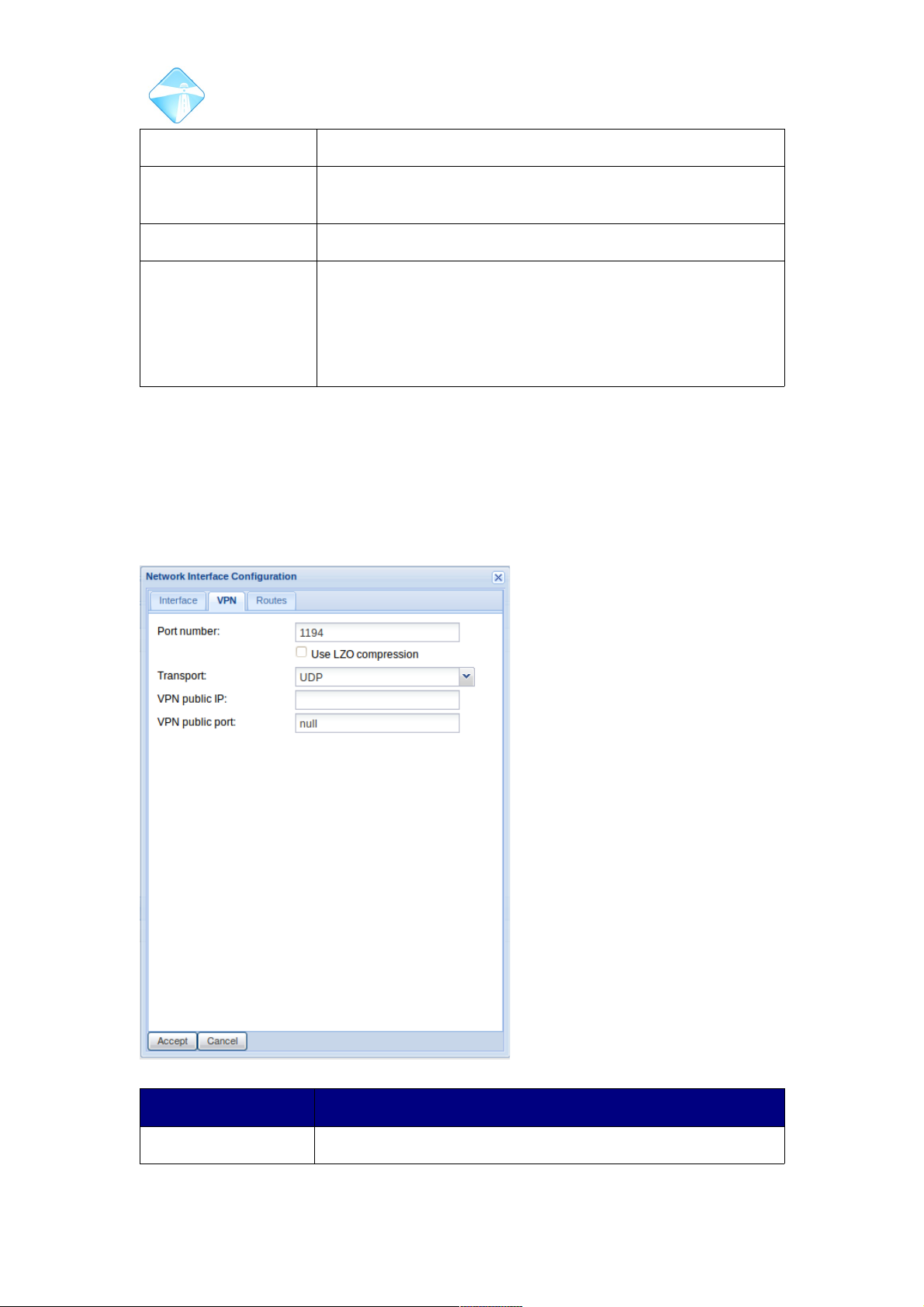
Com.X Administrator Guide
Page 51
VPN servers. The VPN server IP must end in .1.
Network Mask The network mask of the interface. Automatically configured
on client interfaces.
Gateway N/A
Default Metric The metric of a network route is a property used by a routing
protocol to determine whether one particular route should be
chosen over another.
In conflicting cases, traffic will be directed towards the
gateway containing the lowest value metric.
3.2.5.2.1 VPN Server
By default a disabled VPN server port is configured on the Com.X. To configure,
right-click the interface in the interfaces list and select edit. The VPN interface
configuration as in Figure 38 will load. Configure interface IP settings appropriately,
then select the VPN tab.
Field Contents
Port Number The port to be used by clients to connect to the VPN.
©2010 – 2016 Far South Networks
Figure 39: VPN Server configuration options
Page 52
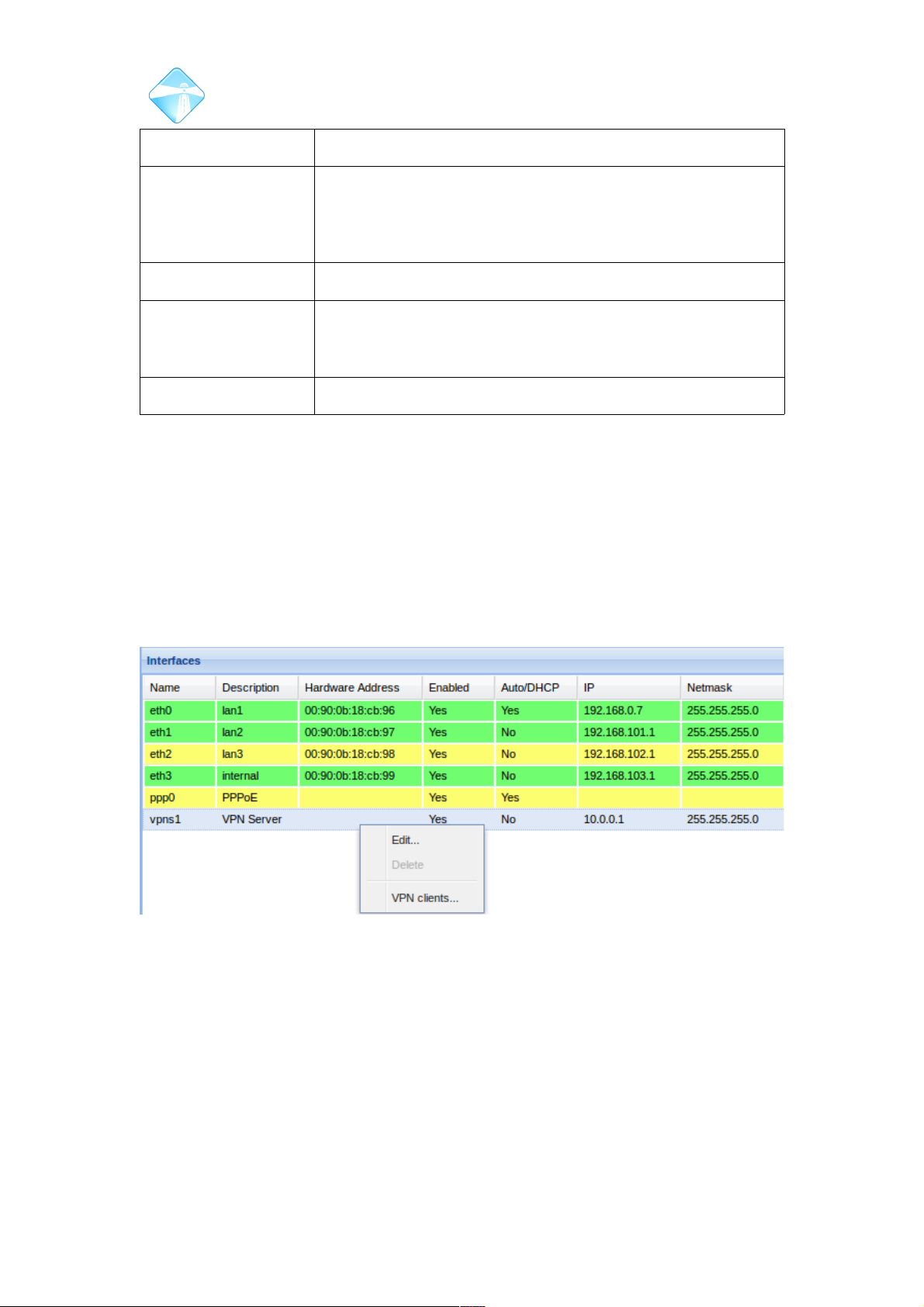
Com.X Administrator Guide
Page 52
Defaults to 1194.
Use LZO
Compression
The VPN may be configured to use compression on all
packets. This will save network bandwidth but incur some
performance penalty. Client and server configuration must
match.
Transport Select between TCP and UDP for VPN transport.
VPN Public IP The Public IP address of the VPN server, if required. This is
used allow client configuration to be generated automatically,
see next section.
VPN Public port The associated port on the public IP of the VPN, if required.
3.2.5.2.1.1Routes
Routes are added by selecting the Routes tab once configuring the interface. Routes
on VPN interfaces are added as with any other network interface as described in
Section 3.2.6
3.2.5.2.1.2Generating certificates for clients
To generate authentication certificates for client devices, right-click on the interface in
the interfaces list, and select VPN Clients. Select New and enter the name of the
client. Review and apply your changes to create the client.
Once a client is created and the configuration applied, a certificate pack and/or
configuration pack for the client can be generated. Right-click the client in the clients
list, and select Get Configuration.
©2010 – 2016 Far South Networks
Figure 40: Select VPN Clients to generate licenses for client devices.
Page 53
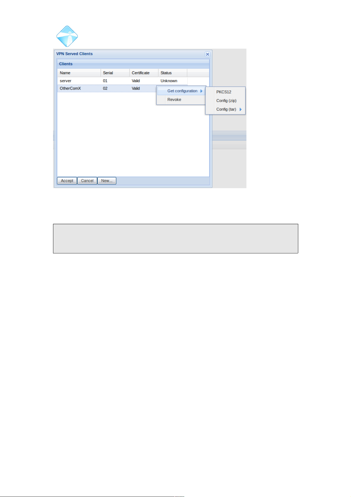
Com.X Administrator Guide
Page 53
Select your desired certificate packaging and save the file to a location on your
desktop/laptop computer.
Note: Changes must be applied after the creation of a client before requesting
configuration. No client configuration is created before the changes are applied, and
so no configuration will available for unapplied clients.
3.2.5.2.1.3Revoking Client certificates
To revoke certification for a client device, right-click on the desired device in the VPN
Served Clients list, and select Revoke. Clients authenticating with revoked certifcates
will be denied. Note that a certificate, once revoked, cannot be used again. A new
client certificate will have to be issued.
3.2.5.2.2 VPN Client
To add a new VPN client interface, navigate to the network page of the Comma GUI
and select Options, New VPN as per Figure 36.
©2010 – 2016 Far South Networks
Figure 41: Certificates are available as standard .p12 or in tar or zip
format, for particular handset devices.
Page 54
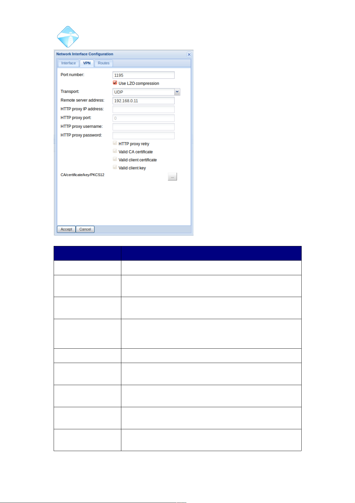
Com.X Administrator Guide
Page 54
Field Contents
Port Number Port number on associated VPN server. Defaults to 1194.
Transport Protocol to be used for traffic on the VPN. Select between
UDP and TCP.
Remote Server
Address
The IP address or hostname of the VPN server hosting the
VPN.
HTTP proxy IP
address
Optional: the IP address or hostname of an HTTP proxy
server via which the VPN server can be contacted. Only
applicable if transport is TCP.
HTTP proxy port Required if HTTP proxy is used: the port of the HTTP proxy
HTTP proxy
username:
An optional username for authentication with the HTTP
proxy
HTTP proxy
password
An optional password for authentication with the HTTP proxy
HTTP proxy retry If checked, try every 5 seconds to connect to the HTTP
proxy if not yet connected
Valid Certificates and
Keys
A properly configured client requires a valid CA certificate,
client certificate and client key. These are uploaded using
©2010 – 2016 Far South Networks
Figure 42: Client VPN configuration.
Page 55
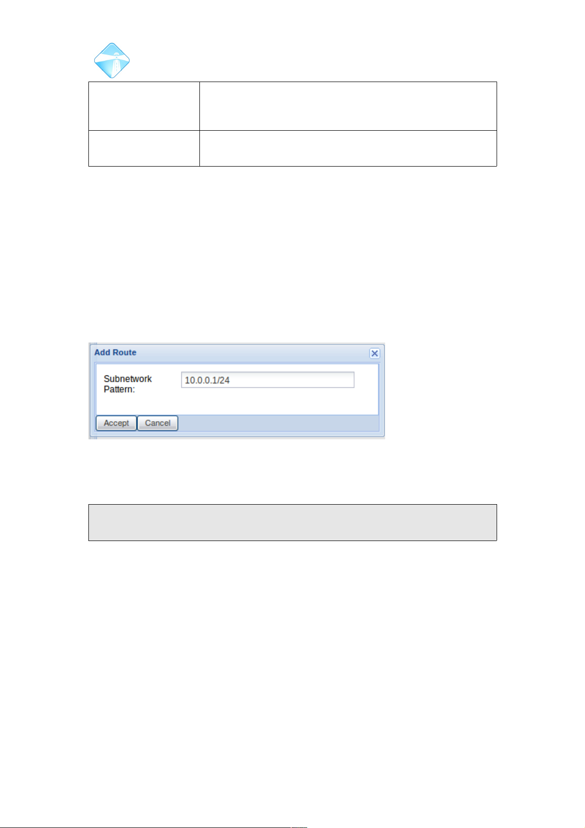
Com.X Administrator Guide
Page 55
the button below, and may be supplied separately (e.g.
ca.crt, client.crt, client.key) or in a PKCS12 package (e.g.
client.p12)
CA/Certificate/key/PK
CS12
Click on the “...” button to upload certificates from your local
file system to your client device.
3.2.6 Adding IP Routes to Interfaces
When an interface is configured with an IP address, an ip route matching that
address and the configured subnet of the interface is autoimatically configured,
associating the port with traffic on the subnet.
Additional routes can be added to an interface, ensuring all traffic to the associated
address(es) is directed through the interface.
Routes can be configured for individual addresses as well as for a range of IP
address, by declaring the subnet range after a '/'.
To configure an IP route, select the desired interface and select the Routes tab and
then the add button.
Click Accept and then review and apply your changes.
Note: After applying network configuration changes, the unit needs to be rebooted
or the networking service restarted.
3.2.6.1 Removing IP Routes from an Interface
Configured routes can be removed from interfaces by selecting the routes tab of the
associated interface, selecting the route, and then clicking the Remove button.
Accept and apply your changes.
©2010 – 2016 Far South Networks
Figure 43: Adding a route to all addresses in the 10.0.0.X range
by declaring the subnet, /24
Page 56
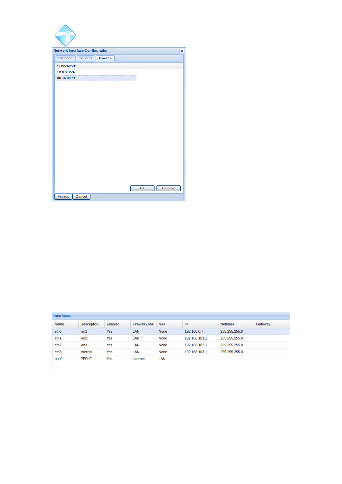
Com.X Administrator Guide
Page 56
Multiple routes can be deleted at once, by using CTRL-click to select all routes
marked for deletion.
3.3 Firewall Configuration
With the on-board firewall option enabled, the Com.X can manage firewall services
on your network.
3.3.1 Zones
The Com.X allows separation of its interfaces into different zones, each of which is
authorized to access only portion s of the available network. The access provided to
devices in each zone is configured through firewall policies (See section 3.3.2)
Configuration for each port can be edited by double-clicking on the desired
appropriate and then selecting the desired firewall zone.
©2010 – 2016 Far South Networks
Figure 44: Managing IP routes on an interface.
Figure 45: Ports can be allocated a particular zone into which they fall.
Page 57
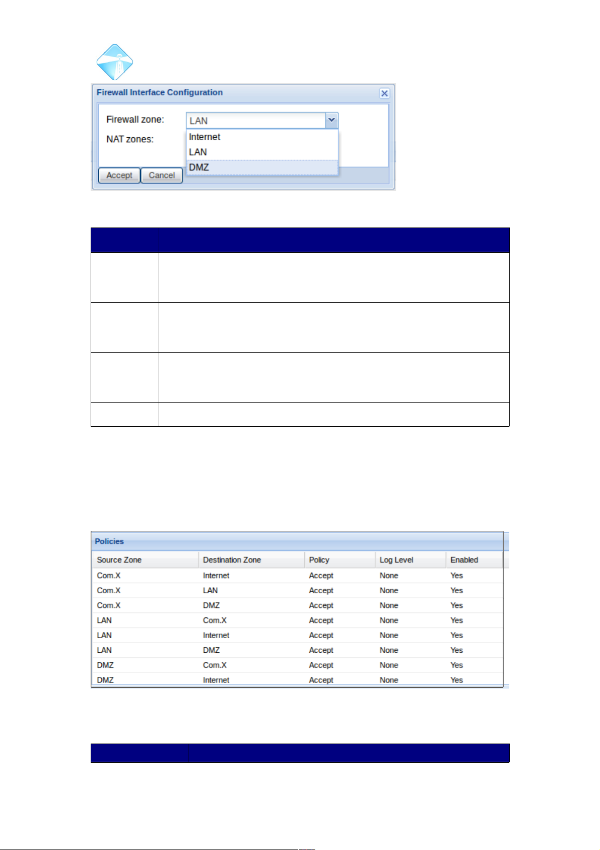
Com.X Administrator Guide
Page 57
Zone Access
Com.X The Com.X zone contains interfaces (physical and virtual) on the
Com.X system itself. This includes the ports listed on the interfaces
section of the Network page of the Com.X GUI.
LAN Interfaces placed in the LAN zone have access only to the internal
network. The internet and any external destination is only reachable
through another device in the DMZ.
DMZ The De-militarized zone has access both to the internet and a limited
partition of the internal network. Interfaces in this zone are typically
used to provide services to users on the external network.
Internet This zone holds any devices on the external internet.
3.3.2 Policies
Policies are used to control the access available to each firewall zone (see section
3.3.1) Policies are explicitly configured to provide a standard way of dealing with
traffic moving from one zone to another.
A policy can be configured to respond in one of three ways:
Policy Action
©2010 – 2016 Far South Networks
Figure 46: Ports can be allocated into one of four default zones.
Figure 47: Policies are listed showing source and destination zones.
Page 58
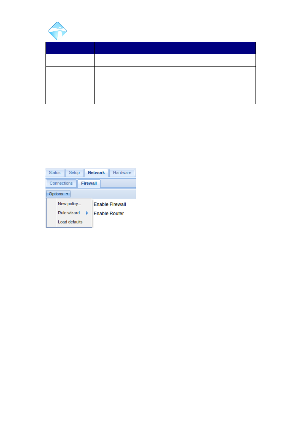
Com.X Administrator Guide
Page 58
Accept Allow traffic between the two zones.
Drop Ignore any packets travelling from the source zone to the
destination zone.
Reject Reject any packets sent from the source zone to the destination
zone with a rejection message.
3.3.2.1 Applying Default Policies
A comprehensive suite of firewall policies are available for restoration on each
system. These policies include what we at Far South believe should be a good “out
of the box” policy configuration that would need particular rules and perhaps
additional policies to be configured in order to meet the needs of the client.
To add the default policy suite to your configuration, select the Firewall page of the
Network tab, and then the Load Defaults option from the options list.
Default Policies:
©2010 – 2016 Far South Networks
Figure 48: Add the default firewall
policies to your configuration.
Page 59
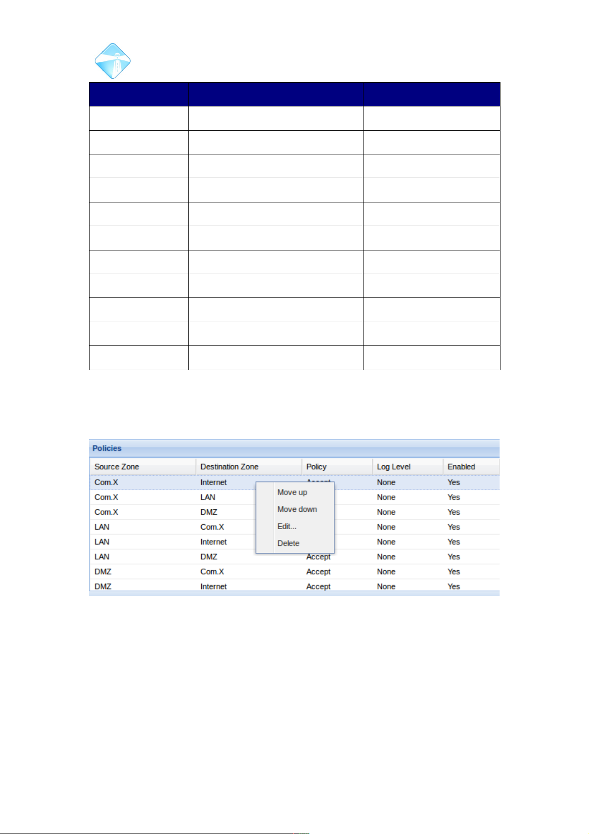
Com.X Administrator Guide
Page 59
Source Zone Destination Zone Action
Com.X Internet Accept
Com.X LAN Accept
Com.X DMZ Accept
LAN Com.X Accept
LAN Internet Accept
LAN DMZ Accept
DMZ Com.X Accept
DMZ Internet Accept
DMZ LAN Drop
Internet All Zones Drop
All Zones All Zones Reject
Table 3: Com.X Firewall default policies.
3.3.2.2 Managing Policies
Policies are evoked in preferential order based on their position in the list on the GUI.
By right-clicking on a policy, it can be moved up and down, deleted and edited.
3.3.2.3 Editing Policies
To edit a policy right-click the policy and select edit. This edit does not allow the
changing of source and destination zones (for that a new policy is required) but
allows the resultant action to be changed (choosing between Accept, Reject and
Drop) as well as select the type of logging required for traffic evoking this policy.
Further, a policy can be disabled, and a disabled policy re-enabled.
©2010 – 2016 Far South Networks
Figure 49: Policy Management and preference manipulation.
Page 60
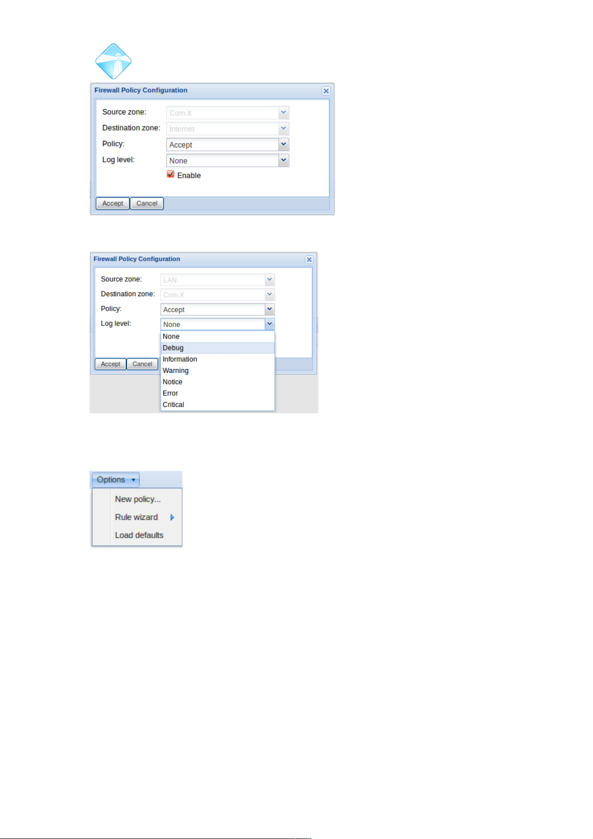
Com.X Administrator Guide
Page 60
Figure 50: Editing an existing Firewall policy.
3.3.2.4 Creating a New Policy
To create a new firewall policy, select Options, then new policy.
©2010 – 2016 Far South Networks
Figure 51: Logging Options for firewall policies.
Figure 52: Options
for new rules and
policies.
Page 61
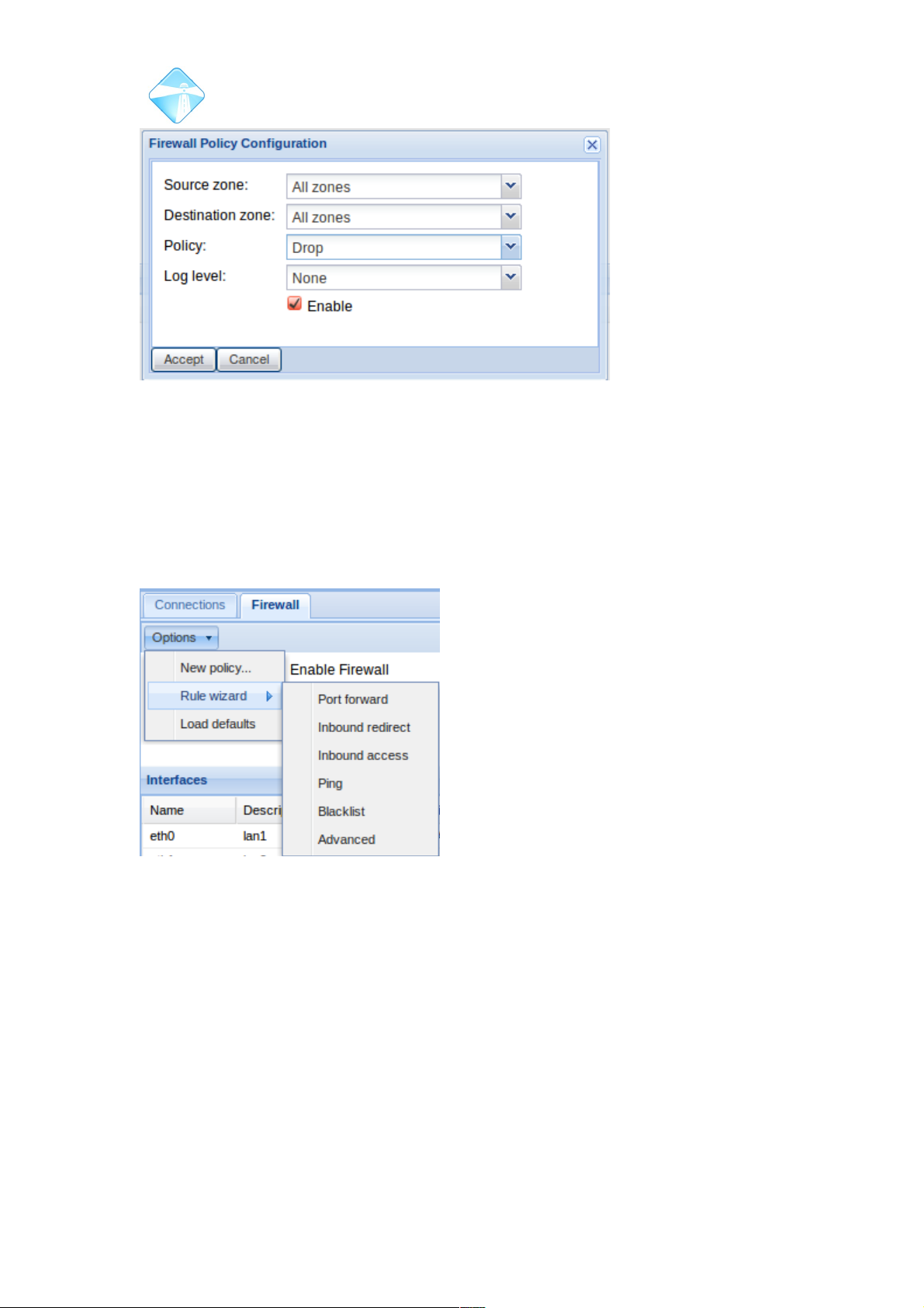
Com.X Administrator Guide
Page 61
3.3.3 Rules
Rules are very specific exceptions to the configured policies. Rules allow the
forwarding of ports. Rules allow for traffic to move from particular ports or addresses
in a manner that would normally be prevented by the policies.
To configure a new rule, select Rule Wizard from the options menu of the Firewall
page and select the type of rule you wish to configure.
Each Rule type makes use of the same rules parameter sheet, with certain fields preconfigured depending on the type of rule.
3.3.3.1 Port Forward
To forward a single port or a range of ports to the firewall, you can use the port
forwarding rule wizard.
©2010 – 2016 Far South Networks
Figure 53: Configuring a new firewall policy.
Figure 54: Rule Wizard . Types of
configurable rules.
Page 62
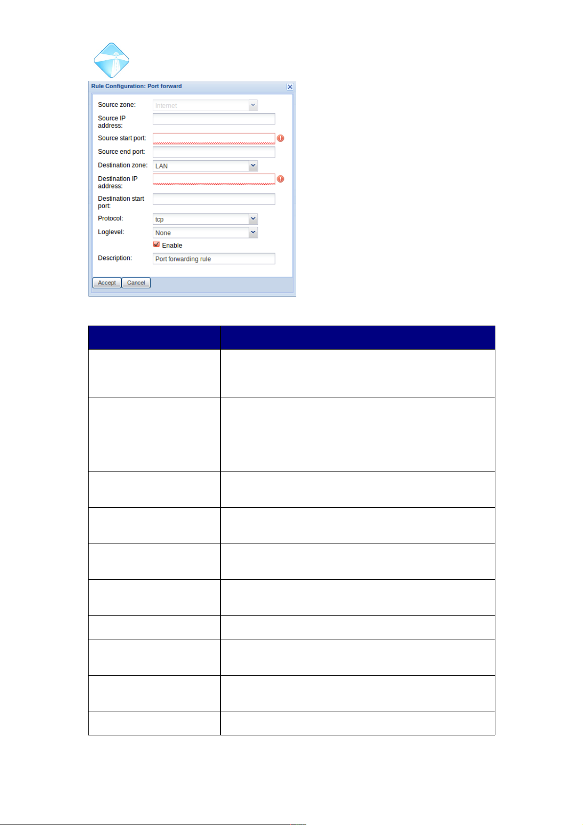
Com.X Administrator Guide
Page 62
Illustration 1: Port Forward rule wizard
Field Description
Source Zone Since this is the port forward rule wizard, the source
zone is automatically configured to “Internet” and can
not be edited.
Source IP address If required, access to the port forward rule can be
restricted to a particular source IP address or address
range. To configure an IP range, specify the non-zero
bits of the netmask numerically after a / character.
<ip_address>/<numerical_netmask>
Source start port The start port of the source which you would like to be
able to access this port forward rule.
Source end point The end port of the source which you would like to be
able to access this port forward rule.
Destination Zone The allocated zone of your destination device. For port
forward rules this option is limited to LAN and DMZ.
Destination IP address The ip address of the destination device to be accessed
by this port forward rule.
Destination start port The start port to be accessed on the destination device.
Destination end port The final port in the range to be accessed on the
destination device.
Protocol The communication protocol that will be available on
this rule. Select between tcp and udp.
Loglevel The logging tag you would like attatched to any logging
©2010 – 2016 Far South Networks
options.
Page 63
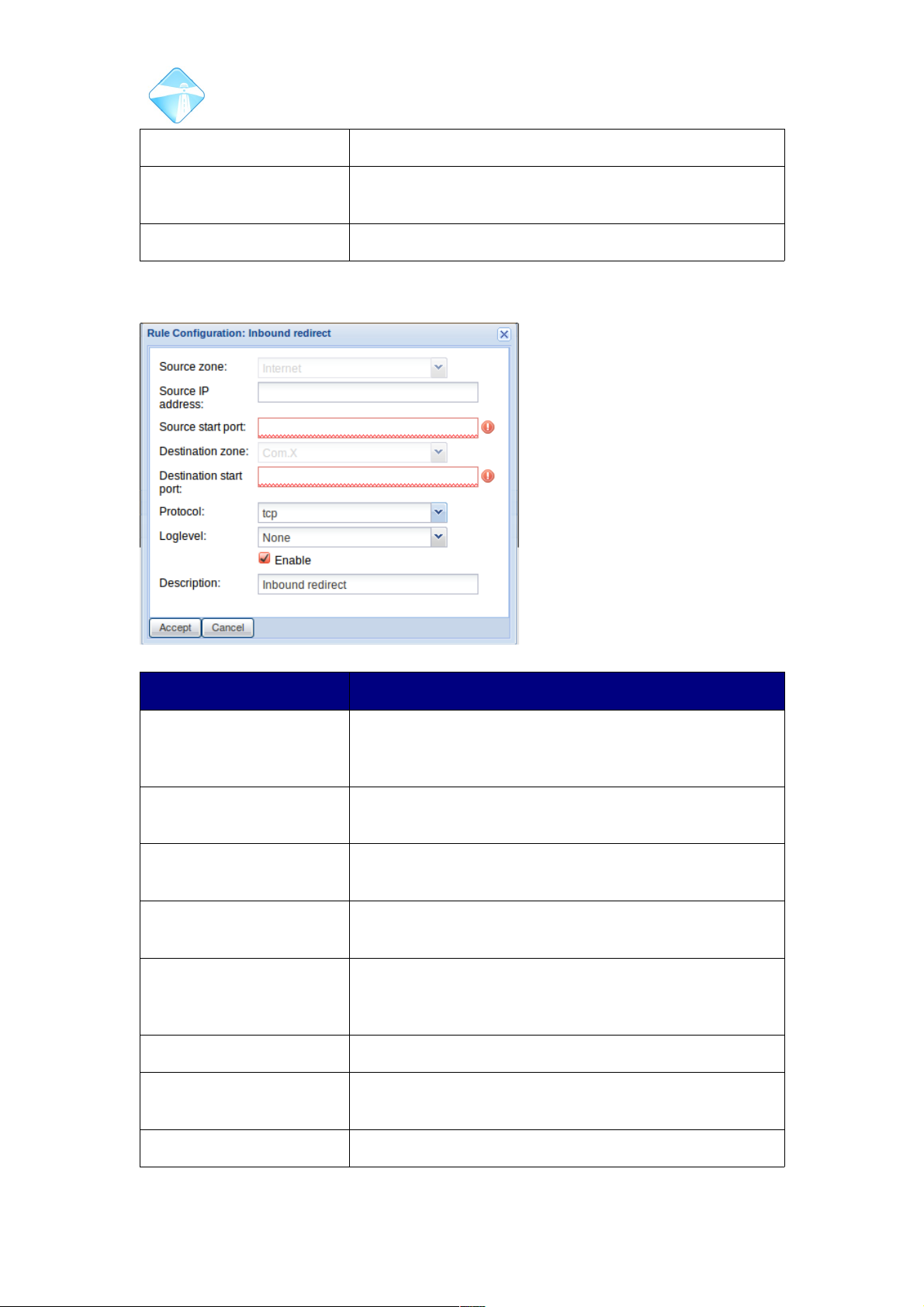
Com.X Administrator Guide
Page 63
on this route.
Enable An Enable toggle. If unchecked, the rule will not be
active.
Description An optional description for the firewall rule.
3.3.3.2 Inbound Redirect
Field Description
Source Zone In a redirect rule, the source will always be in the
internet zone, so this field has been preconfigured and
can not be edited using the rule wizard.
Source IP address Access to this rule can be limited to a single IP address
or a range of IP addresses on the same subnet.
Source start port The start port of the source which you would like to be
able to access this rule.
Source end point The final port of the range of ports on the source which
you would like to be able to access this rule
Destination Zone The allocated zone of your destination device. As this is
an inbound redirect rule, the zone is pre-configured to
Com.X and can not be editted from the rule wizard.
Destination start port The port to be accessed on the destination device.
Protocol The communication protocol that will be available on
this rule. Select between tcp and udp.
Loglevel The logging tag you would like attached to any logging
©2010 – 2016 Far South Networks
Figure 55: Inbound Redirect rule wizard.
Page 64
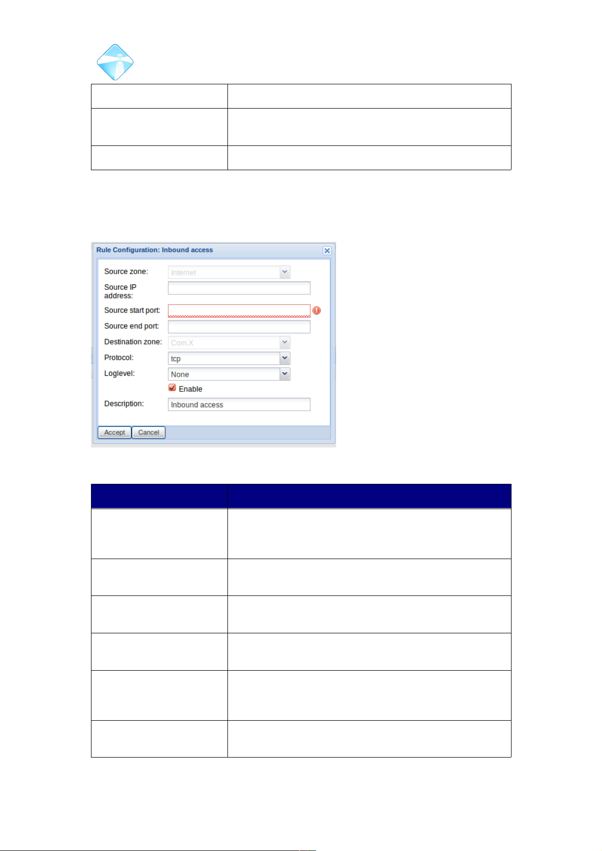
Com.X Administrator Guide
Page 64
on this route.
Enable An Enable toggle. If unchecked, the rule will not be
active.
Description An optional description for the firewall rule.
3.3.3.3 Inbound Access
An inbound access route can be configured to allow access to the Com.X device
from particular devices on the external internet.
Field Description
Source Zone In a redirect rule, the source will always be in the
internet zone, so this field has been preconfigured and
can not be edited using the rule wizard.
Source IP address Access to this rule can be limited to a single IP address
or a range of IP addresses on the same subnet.
Source start port The start port of the source which you would like to be
able to access this rule.
Source end point The final port of the range of ports on the source which
you would like to be able to access this rule
Destination Zone The allocated zone of your destination device. As this is
an inbound access rule, the zone is pre-configured to
Com.X and can not be edited from the rule wizard.
Protocol The communication protocol that will be available on
this rule. Select between tcp and udp.
©2010 – 2016 Far South Networks
Figure 56: Inbound access rule wizard.
Page 65
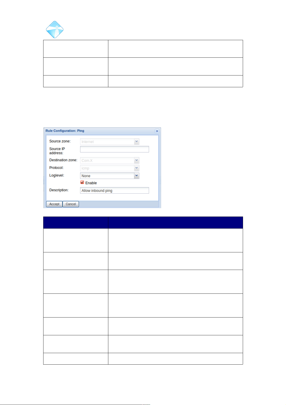
Com.X Administrator Guide
Page 65
Loglevel The logging tag you would like attached to any logging
on this route.
Enable An Enable toggle. If unchecked, the rule will not be
active.
Description An optional description for the firewall rule.
3.3.3.4 Ping
A ping rule allows the Com.X device to receive and respond to pings sent from
particular devices in the internet zone (i.e. not on the local network, but rather on the
external internet).
Field Description
Source Zone In a ping rule, the source will always be in the internet
zone, so this field has been preconfigured and can not
be edited using the rule wizard.
Source IP address Access to this rule can be limited to a single IP address
or a range of IP addresses on the same subnet.
Destination Zone The allocated zone of your destination device. As this is
an inbound access rule, the zone is pre-configured to
Com.X and can not be edited from the rule wizard.
Protocol As this is a wizard for a ping rule, only icmp traffic is
permitted. This field can not be edited on this type of
rule.
Loglevel The logging tag you would like attached to any logging
on this route.
Enable An Enable toggle. If unchecked, the rule will not be
active.
Description An optional description for the firewall rule.
©2010 – 2016 Far South Networks
Figure 57: Ping firewall rule wizard.
Page 66
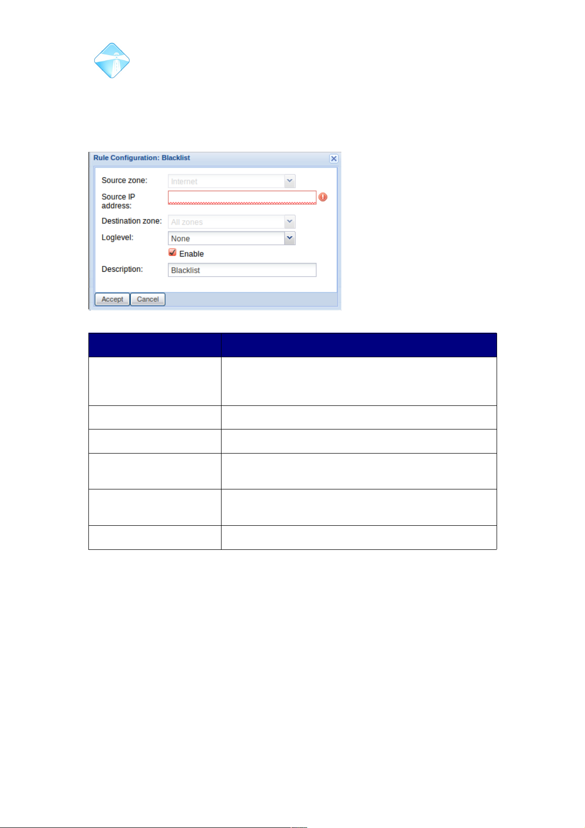
Com.X Administrator Guide
Page 66
3.3.3.5 Blacklist
If required, particular ip addresses or ranges of ip addresses can be black listed by
the administrator. This results in any traffic from the source being rejected.
Field Description
Source Zone In a blacklist rule, the source will always be in the
internet zone, so this field has been preconfigured and
can not be edited using the rule wizard.
Source IP address The IP address (addresses) you would like to blacklist.
Destination Zone All zones are included in a blacklist rule
Loglevel The logging tag you would like attached to any logging
on this route.
Enable An Enable toggle. If unchecked, the rule will not be
active.
Description An optional description for the firewall rule.
3.3.4 Advanced
Should you require some behaviour that can not be achieved with the rule-types
already listed, configuring an advanced rule allows you to manually configure each
field of the rules sheet. This allows for advanced port-by-port traffic routing of your
choice of protocols. We suggest consulting
the shorewall documentation before configuring a rule of this type.
http://www.shorewall.net/
3.3.5 Failed Rules
When using the advanced rule wizard, it is possible to configure a rule that is for
some reason forbidden. This could be a result of a logical flaw, or an unknown
interface.
©2010 – 2016 Far South Networks
Figure 58: Blacklist rule configuration wizard.
Page 67
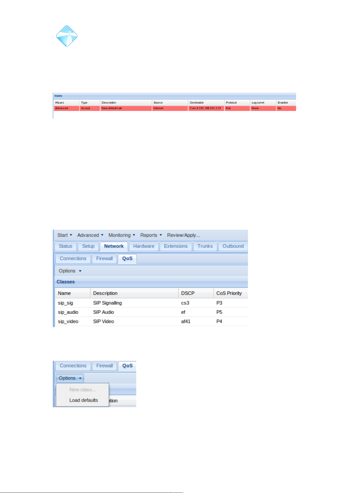
Com.X Administrator Guide
Page 67
If such a rule is present, the “checking firewall services” step will fail in an apply, but
the apply will succeed. The GUI elects to disable the individual rule, but enable the
firewall service and all other configured rules or policies.
Rules that have been disabled due to logical flaws or ambiguities are highlighted in
red and displayed in the rules list.
3.3.6 Network Quality of Service
Network Quality of Service provides a mechanism to differentiate between and
classify various network traffic sources. Each traffic class can be assigned a priority
to allowing preferential queueing and transport treatment of particular streams of
traffic to meet specific needs. By default, three special classes of traffic are
supported: SIP signalling, SIP audio and SIP video. Other, unclassified traffic is left
“as is” by Com.X.
The special traffic classes support the setting of Layer 3 class of service (DSCP) and
Layer 2 class of service (CoS Priority) for traffic generated by the Com.X. DSCP is
generally visible right through the network path, whilst CoS Priority is only used for
the local network queuing priority and on VLAN if configured.
3.3.6.1 Loading network QoS defaults
To load default classification and priority settings, select options, Load Defaults.
Accept that all user changes will be over written, and Review/Apply your
configuration.
©2010 – 2016 Far South Networks
Figure 59: This rule features an unknown interface and so has been disabled and
marked in red.
Figure 60: Network traffic quality of service list
Figure 61: Load default QoS
settings.
Page 68
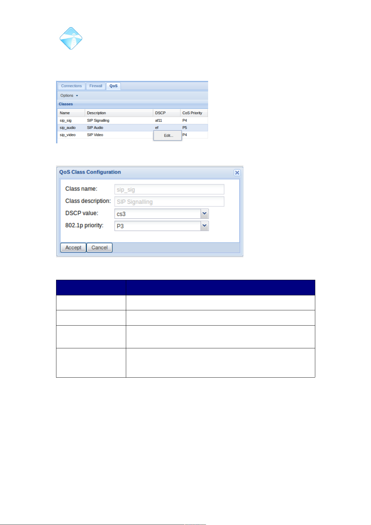
Com.X Administrator Guide
Page 68
3.3.6.2 Editing classification and priority
To edit the classification and priority of a particular type of traffic, right click the entry
in the classes list and select edit.
Field Contents
Class Name sip_sig, sip_audio or sip_video
Class Description Description of above
DSCP Value Differentiated Services Code Point as per RFC 5865.
Unclassified traffic has DF code point.
802.1p priority VLAN priority as per
!"
#$#
3.4 Hardware Device configuration
To list, detect and configure hardware devices (including the Com.X, external iTAs, IP
phones and other network devices), select the Start button, then Configuration and
open the Hardware panel.
©2010 – 2016 Far South Networks
Figure 62: Editting network traffic classes
Figure 63: QoS Class configuration options
Page 69
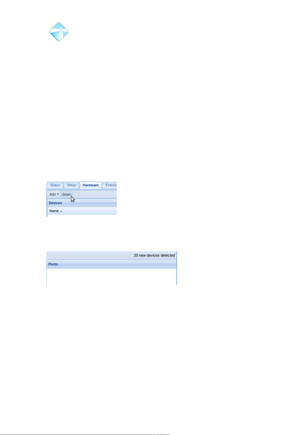
Com.X Administrator Guide
Page 69
3.4.1 Configured devices
The list of configured devices is displayed on the hardware panel. Devices are
classified as follows:
• Generic devices – the IP address and/or MAC address of the device is
known, and the Com.X GUI provides proxy web access to the device. This
class supports generic IP phones, ADSL routers, etc.
• Comma devices – built in telephony hardware and Comma iTA devices
• Managed SIP devices – supported IP phone types that are fully managed by
the Com.X
For each device, the device name, type, model, MAC address and Auto IP values are
listed. Where available, the device IP address and current status are also listed.
3.4.2 Detecting and scanning for devices
The Com.X unit can detect network devices present on all networks attached to it. By
default, devices requesting either DHCP IP information, internal telephony devices
and external Comma iTA devices are automatically added to the list of detected
devices. A scan of all network interfaces can also be initiated by selecting the Scan
button. This process may take a couple of minutes.
The number of devices detected is displayed in the top right corner of the Hardware
panel. To add detected devices to the configuration, select the Add menu item
followed by the Detected menu item.
This results in a list of detected devices from which one can be selected for
configuration. Where available, the existing MAC address, device type, model, IP
address and vendor information is listed.
3.4.3 Adding Detected Devices
Once a device has been detected by the Com.X, navigate to “Add” then “Detected”
and select the device from the list. If the network was scanned to detect the handset,
then the list of detected devices will include several devices and the correct handset
must be selected. Select the appropriate handset and click OK.
©2010 – 2016 Far South Networks
Figure 64: The network can bge scanned for devices from the Hardware panel.
Figure 65: The number of detected devices is displayed on the Hardware panel.
Scanning the network increases the number of detected devices.
Page 70
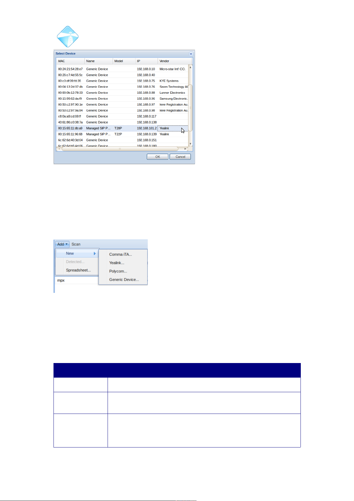
Com.X Administrator Guide
Page 70
3.4.4 Manually adding devices
If a device is not present on the network or does not appear on the detected list, it
can be added manually by providing its MAC address and IP information. Comma
iTAs, Generic devices and Managed SIP devices can be added by selecting the Add
button, followed by the New menu and the desired device type.
3.4.5 Configuring devices
After a device has been selected for configuration, manually added or edited, a
device configuration form will appear:
3.4.5.1 Configuring Comma devices
Double-click an ethernet interface to configure the following fields:
Field Content
Device Name A custom name for the device
Model Type The card configuration of the device. If the device was detected,
this field will be populated automatically.
Auto IP On first boot, request an IP address from the Com.X Manager.
Once an IP has been allocated, the Auto IP field becomes
disabled and the IP is statically reserved for the device by the
Comma Manager, always issuing the same IP to the device
©2010 – 2016 Far South Networks
Figure 66: Selecting the appropriate detected device
after a scan of the network.
Figure 67: Selection of device types to be added.
Page 71

Com.X Administrator Guide
Page 71
Field Content
matching the configured MAC address.
IP Address An IP address unique to the device on the network. Auto-
assigned if Auto IP Client is enabled.
Network Mask The network mask the device should be configured with. Auto-
assigned if Auto IP is enabled.
Gateway The routing gateway the device should use. Auto-assigned if Auto
IP is enabled.
Attached network The network interface to which the device is attached.
Note: the interface selected here must be configured as
providing Comma services, or the addition of the device will fail
with the message 'Device not supported on this interface'. The
Comma device manager only listens on and provides
configuration to devices on boot-up on interfaces configured for
Comma services.
Timing Mode The timing source for the device. Options are:
Local: Recover timing from the local Com.X clock (i.e. this
device is a clock master)
System: Recover timing from another clock master (i.e. this
device is a clock slave) This is equivalent to the iTA
“Network” clocking mode.
Bri/Pri Priority 1: Configure this device to recover clock from
the first active ISDN interface (PRI or BRI)
Bri/Pri Priority 2: Configure this device to recover clock from
the second active ISDN interface (PRI or BRI)
Note: On Com.X5 systems, the primary clock source is
always the system, unless an iTA is configured as clock
master (Line 1 or Line 2) on a PRI or BRI port. When using
an X5 , it is an invalid configuration to configure any iTA as
'local'.
Table 4: Comma device configuration
©2010 – 2016 Far South Networks
Page 72
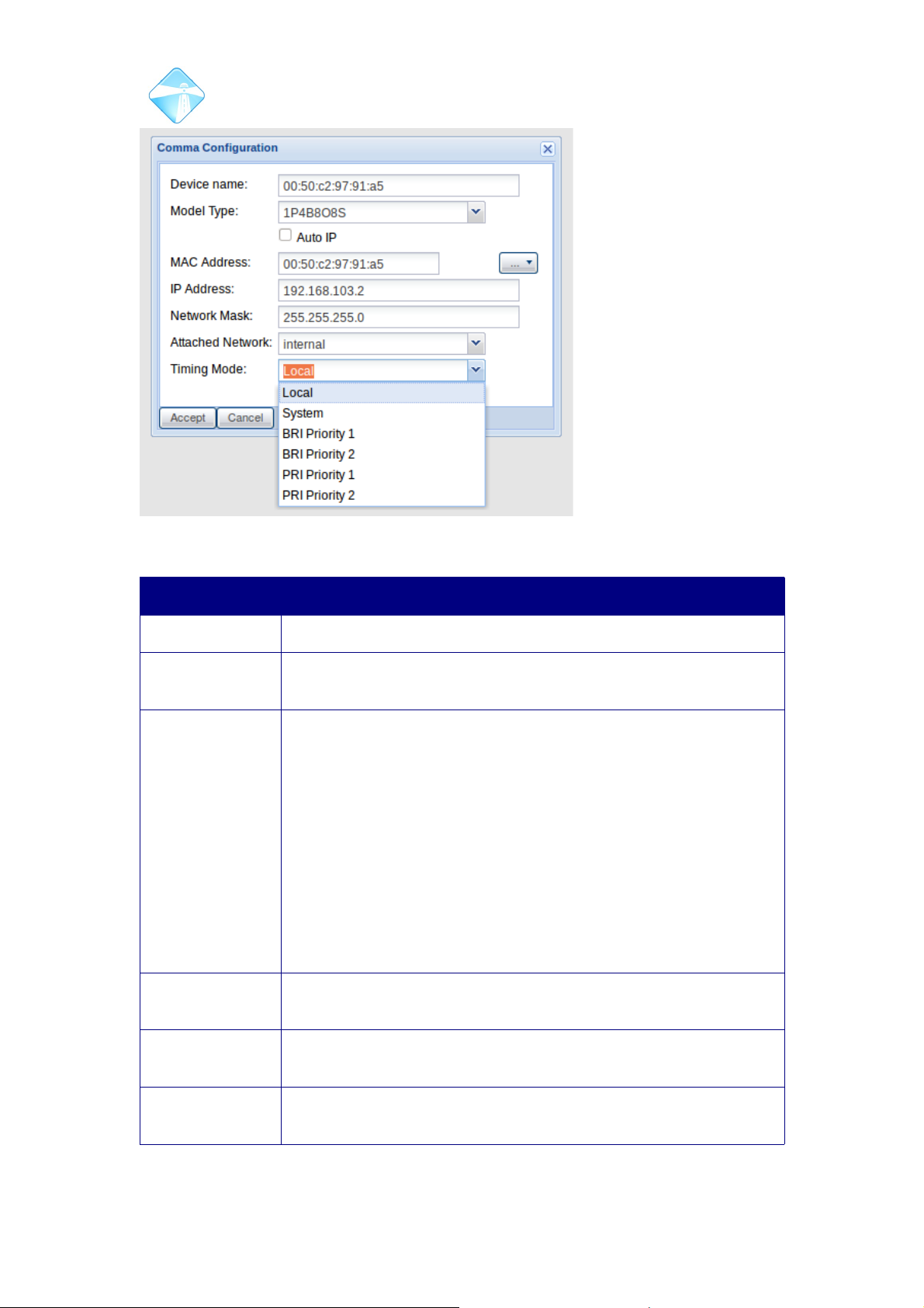
Com.X Administrator Guide
Page 72
3.4.5.2 Configuring Generic devices
Field Content
Device Name A custom name for the device
Model Type The type of the device. In most cases this will remain blank for
manually added generic devices.
Auto IP Indicates whether the Com.X DHCP server should allocate an IP
to the device on DHCP request. Once the DHCP lease on the IP
expires, the Com.X DHCP server might issue a different IP to the
device. To ensure a device is always allocated the same IP
(static), disable Auto IP and enter the IP manually. If the static IP
falls within the DHCP pool, the DHCP server will always allocate
it to the device (i.e. the DHCP client on the device should still be
enabled). If the static IP falls outside the DHCP server IP pool,
the device should be manually configured with the static IP and
its DHCP client disabled.
Please see section 3.2.2.3 for more information on configuring
DHCP services on an interface.
MAC The device's unique hardware address. May be left empty if an IP
address is provided.
IP Address An IP address unique to the device on the network. Auto-
assigned (leave empty) if Auto IP Client is enabled.
Network Mask The network mask the device should be configured with. Auto-
assigned if Auto IP is enabled.
Table 5: Generic device configurationSip Handset Provisioning
©2010 – 2016 Far South Networks
Figure 68: Comma device configuration
Page 73
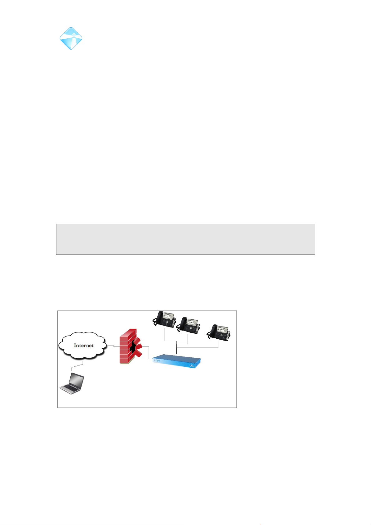
Com.X Administrator Guide
Page 73
3.5 Managed Sip phone provisioning
SIP handsets can be configured and manipulated in various ways directly from the
Com.X GUI.
For each phone added to the hardware list, a corresponding .cfg file, marked as
unique to the handset with a matching MAC address, is created and stored within
/etc/commagui/autoprovision/, where each phone manufacturer and then model, is
allocated its own folder containing the .cfg files of all similar handsets. Changes
made on the GUI are reflected in these files, which are requested by their
corresponding handsets on start up.
A configuration backup of the system will back up these files to the backup archive.
Should an archive be restored, in which configuration files are present, they will be
restored to the correct folder within /etc/commagui/autoprovision/ after the restore
has been applied. Restoring the factory default .tar.gz archive on the Com.X unit will
result in these files being deleted and the Com.X losing all association to the phone.
Each handset will have to be re-added to the hardware panel to allow configuration of
any of the settings mentioned.
Note: If the phone connects to a network with a DHCP server other than the Com.X
present, the DHCP server should configure option 66 to refer to the Com.X when
responding to phone DHCP requests.
Much like a firewall is able to block unwanted traffic by forwarding selected ports on
the Com.X to be visible from the internet, the Com.X is able to port-forward traffic to
the handsets so that they sit behind the Com.X, but can still be safely accessible
from the internet. This allows for the installation of unconfigured phones on site, to be
configured remotely at a later stage.
This means that an array of phones can sit behind a firewall, and be configured
remotely.
©2010 – 2016 Far South Networks
Figure 69: The Com.X forwards and proxies the necessary
traffic to the handsets so that they can sit safely behind a
firewall and still be configured remotely.
Page 74
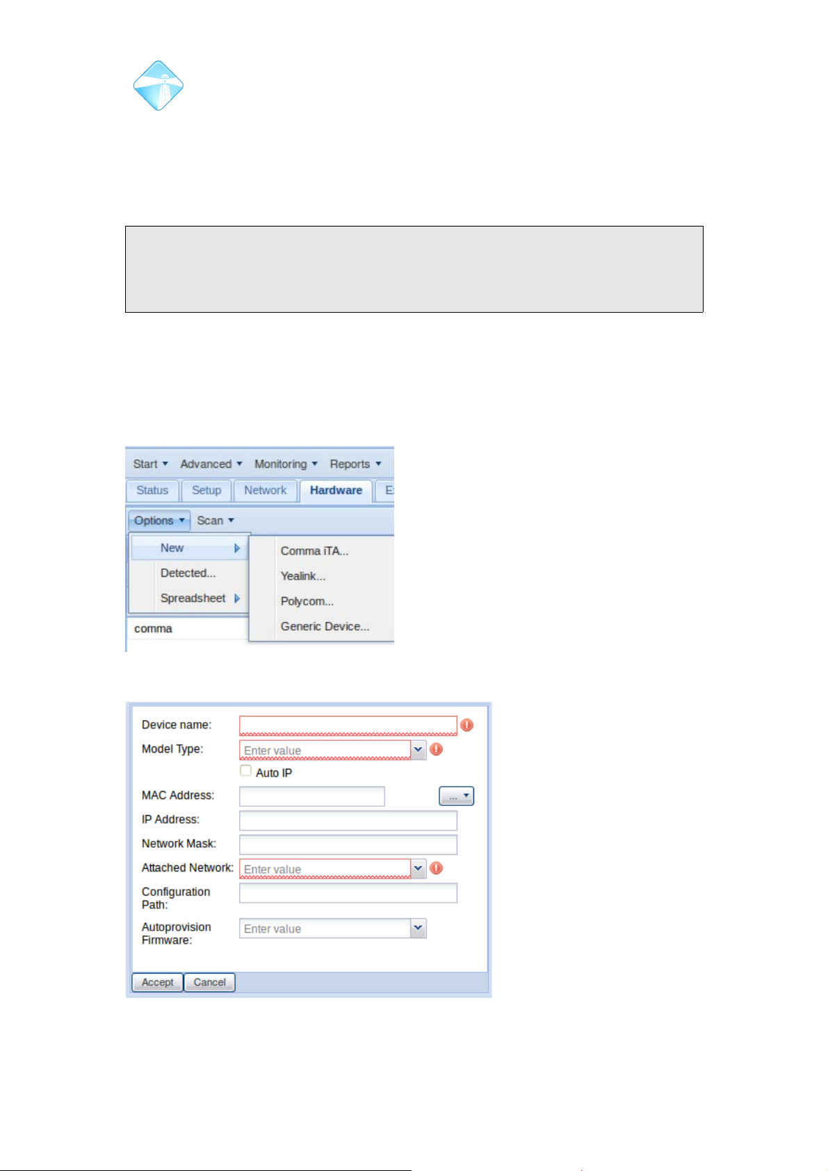
Com.X Administrator Guide
Page 74
3.5.1 Adding Hardware (Managed SIP Device)
In order to configure a sip handset, it needs to be added as a hardware device on the
system.Once a phone is added as a hardware device, the ports of the handset
become visible on the CommaGUI ports tree and are available for configuration.
Note: If a phone is featured on the hardware list, either as a managed SIP phone, or
a generic device, the GUI of the phone can be accessed through the GUI of the
Com.X. This is done by forwarding ports, ensuring that all hardware is available
remotely, even if it is behind a firewall.
3.5.1.1 Manually add Managed SIP Phone
It is possible to manually add a device, without the device even being present on the
network, however the MAC address of the device must be known. This allows for
configuration of units prior to installation, or for the autoprovisioning of handsets that
are receiving DHCP ip addresses from remote servers.
Select Options → New and then select either the manufacturer of your handset.
©2010 – 2016 Far South Networks
Figure 70: Adding Hardware.
Figure 71: Configuration options for a Managed SIP
Phone.
Page 75
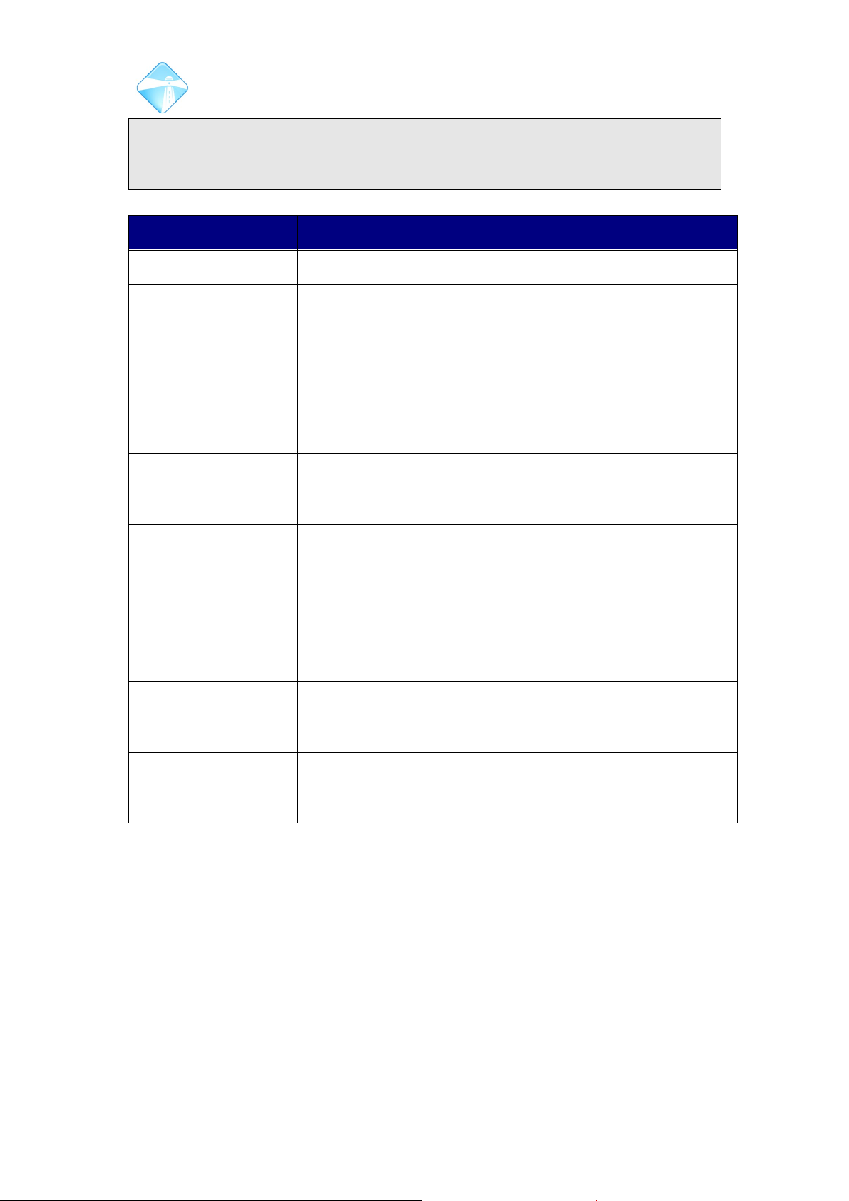
Com.X Administrator Guide
Page 75
Note: If a Managed SIP Phone is receiving DHCP from a remote server(i.e. Not
from the Com.X), that dhcp server should be configured to set option 66 to contain
the location /etc/commagui/autoprovision on the Com.X server.
Field Description
Device Name Choose a suitable name for the device.
Model Type Use the drop down list to select the appropriate model
Auto IP
On first boot, request an IP address from the Com.X
Manager. Once an IP has been allocated, the Auto IP
field becomes disabled and the IP is statically reserved
for the device by the Comma Manager, always issuing
the same IP to the device matching the configured MAC
address.
Mac Address The Mac address of the device being added. This field is used
to identify the device when it is physically connected to the
network.
IP Address An IP address unique to the device on the network. Auto-
assigned if Auto IP Client is enabled.
Network Mask The network mask the device should be configured with.
Auto-assigned if Auto IP is enabled.
Attached Network The network interface through which the device will connect
to the Com.X.
Configuration Path The location on the com.x at which the configuration is stored.
This read only variable can be copied from the GUI if it is
required elsewhere.
Autoprovision
Firmware
If a .rom firmware file has been added to the Com.X via the
file manager, selecting the .rom will install the selected
firmware on the handset.
3.5.1.2 Adding an Auto-detected Managed Sip phone
If a compatible phone is receiving an IP from a DHCP server on one of the ethernet
ports on the Com.X, it should identify themselves as Managed Sip phones. To scan
for a list of devices obtaining IP addresses from the Com.X, select scan and enable
the auto detect option.
©2010 – 2016 Far South Networks
Page 76
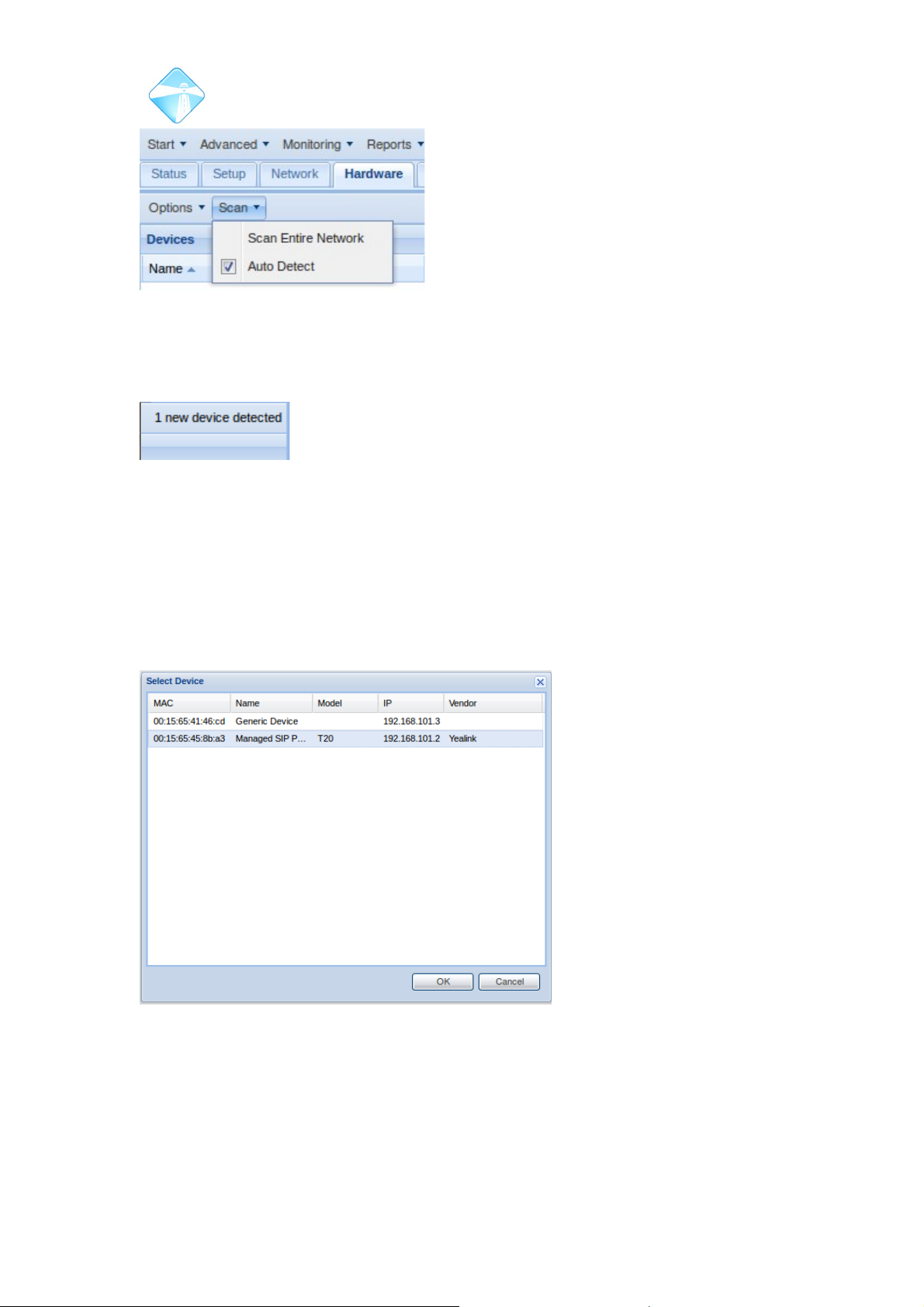
Com.X Administrator Guide
Page 76
You will notice the number of detected devices (displayed in the top right hand corner
of the GUI) increase.
Select Options, and then Detected to see a list of detected phones. Select a
Managed SIP Device.
When configuring an auto-detected device the Com.X automatically detects and
populates all fields with appropriate settings. The name of the device is defaulted to
the Mac address of the unit, and this is the only field that should require (optional)
editing.
©2010 – 2016 Far South Networks
Figure 72: Enable Auto Detect to see a
list of devices receiving an IP address
from the Com.X.
Figure 73: Detected
Devices increases.
Figure 74: Adding Managed devices.
Page 77
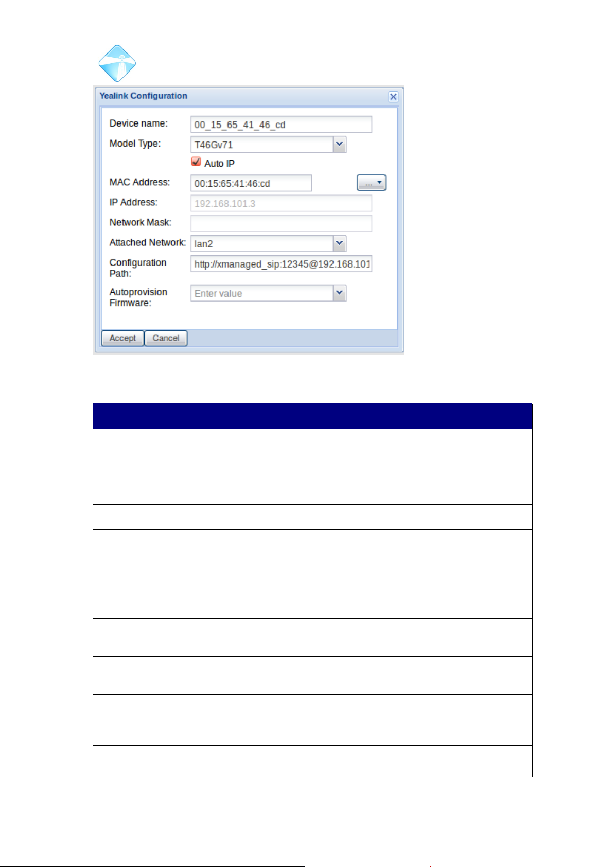
Com.X Administrator Guide
Page 77
Field Description
Device Name Choose a suitable name for the device. By default, this field is
set to contain the MAC address of the device.
Model Type On a Managed SIP phone, the device should automatically
populate this field with its model type.
Auto IP This option is enabled by default for a detected device.
Mac Address This field contains the MAC address of the device, and is
populated automatically for a detected device.
IP Address An auto-detected device will have received its IP address
from a DHCP server on the Com.X, so this field will
automatically be populated by the GUI.
Network Mask The network mask of an auto-detected device will be
automatically configured.
Attached Network This field will be automatically set to the interface serving
DHCP to the auto-detected phone.
Configuration Path The location at which the configuration file for autoprovision is
stored. This read-only variable is available to be copied and
pasted from the GUI.
Autoprovision
Firmware
If any compatible .rom firmware files have been uploaded to
the Com.X, they will be available as choices here. Selecting
©2010 – 2016 Far South Networks
Figure 75: Auto-detected Managed SIP Device configuration
options.
Page 78
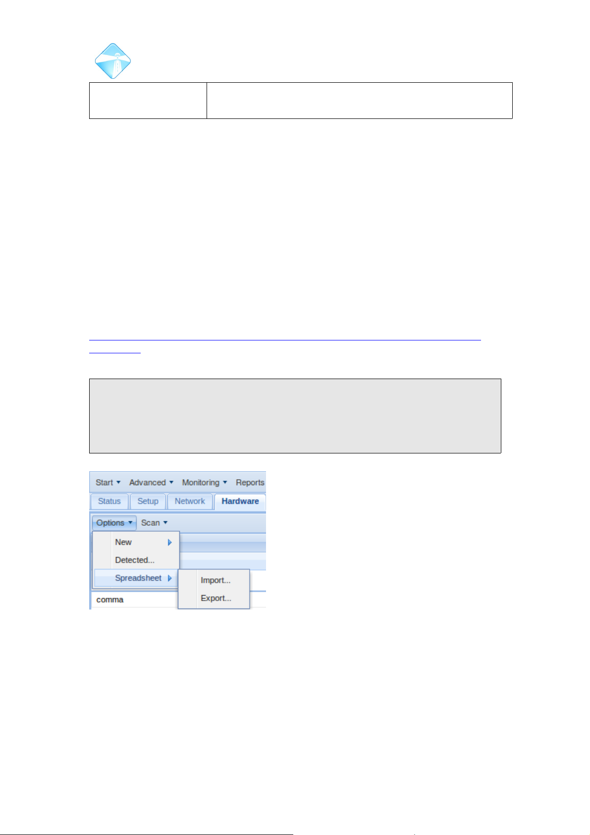
Com.X Administrator Guide
Page 78
any .rom file in this field will install the selected firmware on
the device.
Accept and Review/Apply your configuration changes.
3.5.1.3 Provisioning via Spreadsheet based configuration
For larger installations, featuring several sip endpoints,spread sheet provisioning is a
very powerfull tool. Various fields are configurable on the spreadsheet and will be
automatically added to the configuration of the phones, once the Com.X detects
them.
3.5.1.3.1 Adding hardware via spreadsheet
To add hardware via spreadsheet, first prepare a spreadsheet containing your
handsets, extension numbers and settings (voicemail, DNS, NAT etc).
Navigate to Options and select Spreadsheet the import. Browse for your spreadsheet
file and select ok.
A sample spreadsheet for you to work from is available at:
http://www.farsouthnet.com/wp-content/uploads/2013/08/Com.X-IP-phone-configsample.xls
Note: The fields listed in the spreadhseet can vary and not all options need be
configured. It is recommended that anyone using spreadhseets to configure phones
first manually add a few managed sip phones to a unit and then export a
spreadhseet of the configuration, which can be used as a template for all future
configurations. See Section 3.5.1.3.2 for details on exporting a spreadsheet.
©2010 – 2016 Far South Networks
Figure 76: Options to import or
export hardware spreadsheet files.
Page 79
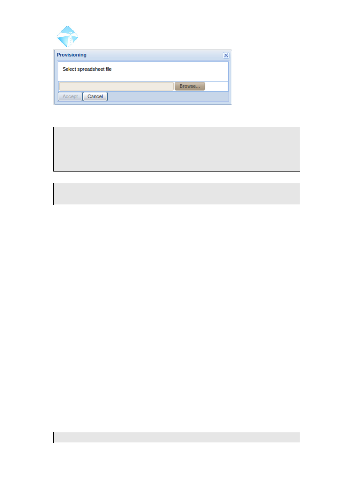
Com.X Administrator Guide
Page 79
Note: Provisioning from a spreadsheet will configure the extension automatically.
Spreadsheets should not contain extension numbers for any existing extensions. If
an existing extension number is present on the spreadsheet, it will be deleted and
replaced by a new extension of the same number, featruing the configurations of the
spreadsheet entry.
Note: If a handset in the spreadsheet already exists on the Com.X (identified by
MAC address) the handset will be updated with the settings from the spreadsheet.
3.5.1.3.2 Exporting spreadsheet of current hardware and extensions
The GUI can produce a spreadsheet export of your current hardware and extension
configuration. This export can be useful as a template, where only mac addresses
and other optional changes need to be made from system to system.
To export your hardware and extensions select Options, Spreadsheet and then
Export.
3.5.2 Adding a Managed SIP phone from a VLAN interface
For a variety of security and performance reasons, it may be desireable to host SIP
handsets on a virtual LAN.
In order to configure a managed SIP device to reside on a VLAN, a VLAN interface
needs be configured as in Section 3.2.5.1.
In order for the DHCP server on the VLAN interface to provide DHCP to the handset,
the phone needs first to be configured to connect to the VLAN. This can be easily
achieved by configuring DHCP server on both the physical interface and the VLAN,
as per Section 3.2.2.3.
Connect your handset to the physical LAN port (most likely through a switch) and
power up the phone.
Ensure that auto-detection of hardware is enabled, and add the handset from
deteced devices, as in Section 3.4.3.
On booting, the phone will initially receive a DHCP adddress from the DHCP server
on the physical LAN interface. Click accept, but do not apply.
Before applying the configuration of the handset, edit the associated LAN interface
and select the VLAN interface from the drop down list. Accept and Review/Apply.
Note:The drop down list is not visible when adding the handset. You will need to first
©2010 – 2016 Far South Networks
Figure 77: Browse for the appropriate spreadsheet file.
Page 80
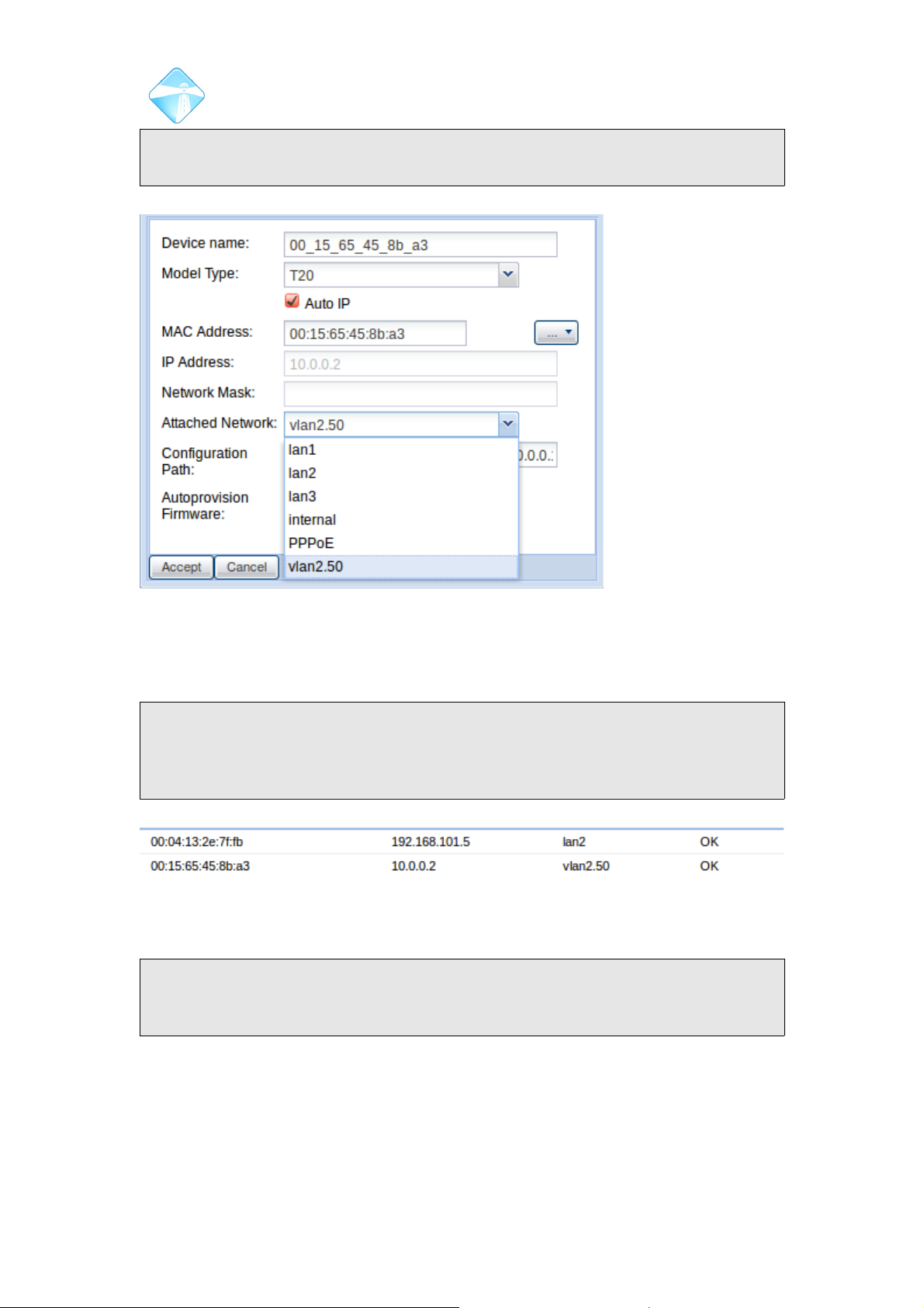
Com.X Administrator Guide
Page 80
accept the handset configuration, then right-click and edit the hardware entry before
the other interfaces become available for selection
The phone should then detect the changes to it's network settings and reboot itself, if
this does not happen automatically, reset the handset to factory default settings from
the GUI. On reboot, the phone will retrieve it's updated configuration.
Note: Upon the phone booting, the review/apply button on the GUI may become
bold. If this occurs, REVERT your configuration, to update the IP address field on
the managed SIP phone. Only apply from the review/apply button once the
managed SIP phone shows both the correct VLAN interface and IP address.
Note: With certain handsets, the DHCP settings remain set until the interface goes
down, so it may be necessary to physically remove and replace the network cable,
or induce a power break cycle before the phone reconfigures itself to the VLAN.
If it is not feasible to enable DHCP server on the physical LAN (e.g. because of
another DHCP server on the LAN), the phone must be manually pre-configured to
attach to the VLAN so that it can receive its IP address and auto provisioning
information from the DHCP server on the VLAN.
©2010 – 2016 Far South Networks
Figure 78: Select the VLAN interface as the attached network
field
Figure 79: This shows one handset residing on a network on LAN2, whilst another
phone, connected to the same physical LAN port, resides on the virtual network hosted
by VLAN2.50.
Page 81
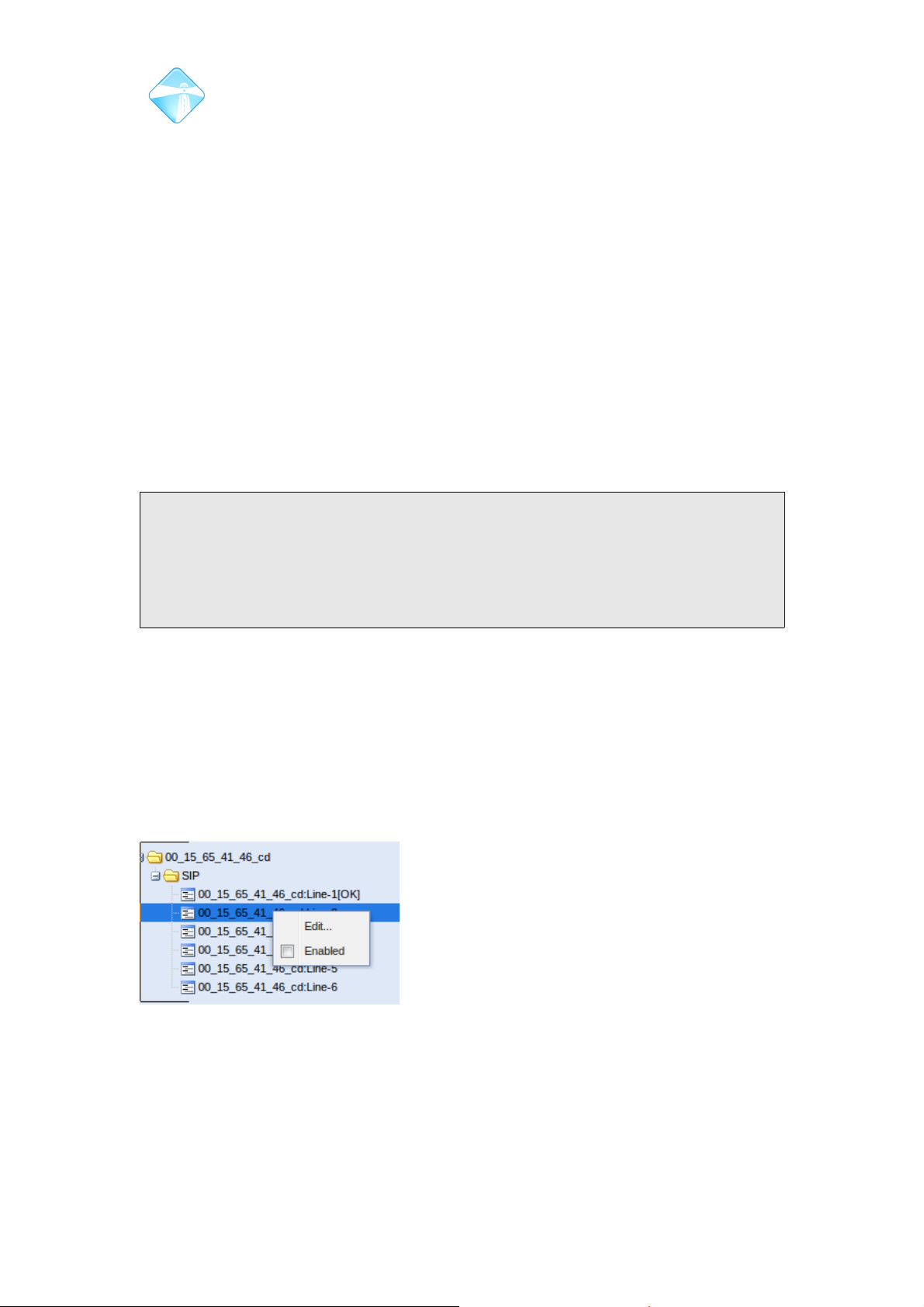
Com.X Administrator Guide
Page 81
3.5.3 Removing a hardware device
To remove a device that has been added as hardware, simply right-click the device in
the hardware list, and select remove. Once you apply the device and its ports will be
removed from the GUI. Any extensions configured on the ports become free
extensions, but remain in any inbound routes, ring groups or queues.
3.5.4 Restore Factory Defaults of a Managed handset
To restore factory default configuration of a managed phone, right-click on the phone
in the device list and select the Factory Defaults option. This will delete any nondefault configuration on the phone.
If you have the phone any extensions configured on the phones ports, the phone will
receive this configuration when it starts up. To have the phone remain in a factory
default configuration, first delete or unassign extensions on the phones ports and
then factory default the phone.
Note: It is recommended that any phones that are added be factory defaulted as a
part of their initial configuration. It is not possible to reassign lines on devices if they
are already assigned to extensions, the association to the extension must first be
deleted. Factory defaulting phones as you install them deletes any extensions
configured in a previous installation and ensures that the Com.X is able to configure
all lines seamlessly.
3.5.5 Configuring Extensions on a Managed Sip phone
By default, Line1 of any Managed Sip Phone will be enabled. Any further lines will
first have to be enabled before they can be configured to support and extension.
3.5.5.1 Enabling Lines
To enable a line on a Managed Sip Device. Select the device in the hardware list.
Find the desired line from the ports tree on the right hand side of the GUI. Right-click
the line and tick the Enabled box.
3.5.5.2 Assigning Extensions to Managed SIP Devices
Extensions can be assigned to the enabled lines of Managed SIP Devices using one
of two methods:
©2010 – 2016 Far South Networks
Figure 80: Enable the line on the
device.
Page 82
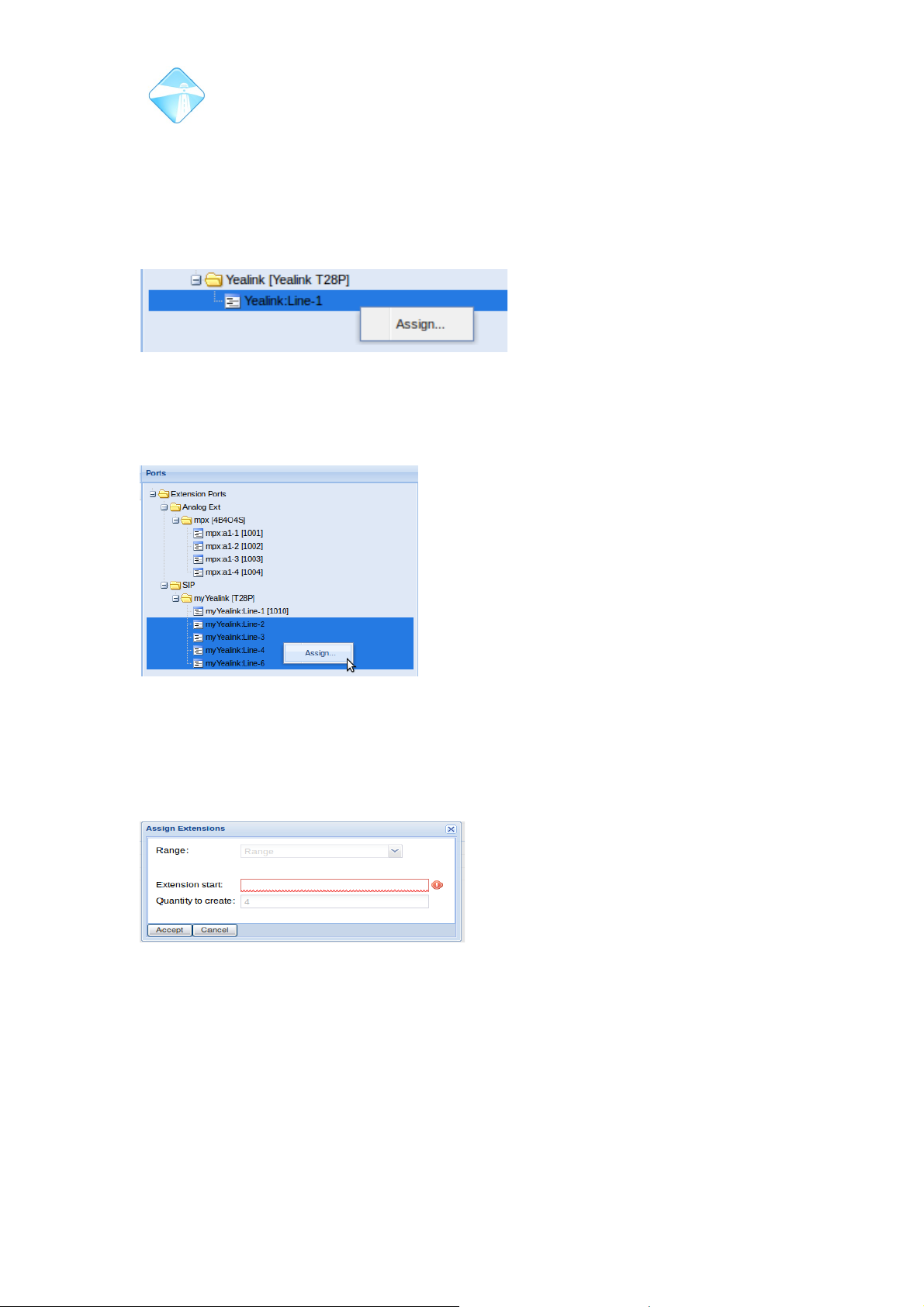
Com.X Administrator Guide
Page 82
3.5.5.3 Creating New Extensions
Extensions that have yet to be created can be created and assigned to the Managed
SIP Device simultaneously.
To create new extensions that are assigned to the Managed SIP Device, navigate to
the Extensions page of the GUI and right-click the particular line on the device in the
ports list. Then select Assign.
Multiple extensions, with consecutive DID numbers can be assigned to multiple lines
on the device by holding 'Ctrl' while selecting individual lines, then right-clicking and
selecting assign.
Enter the DID of the starting extension, this extension will be assigned to the first
selected line on the handset. The other selected lines on the device will be assigned
extensions with consecutive numbers.
3.5.5.4 Assigning free extensions to available lines on Managed SIP Device
A free extension configured on the system can be assigned to an available line on a
SIP handset. Left-click the appropriate line in the port tree of the Extensions page of
the Com.X GUI and (while holding left click) drag the line over the entry of the
desired free extension and then release.
A green tick icon indicates that the selected extension is available for assigning,
whilst a red cross icon indicates that an extension is not available to be assigned.
©2010 – 2016 Far South Networks
Figure 81: Right click the appropriate line in the
ports tree to assign it a new extension.
Figure 82: Consecutive extensions can be created and assigned to multiple
lines on the same device.
Figure 83: Four extensions will be created
and assigned to the lines of the same
handset.
Page 83
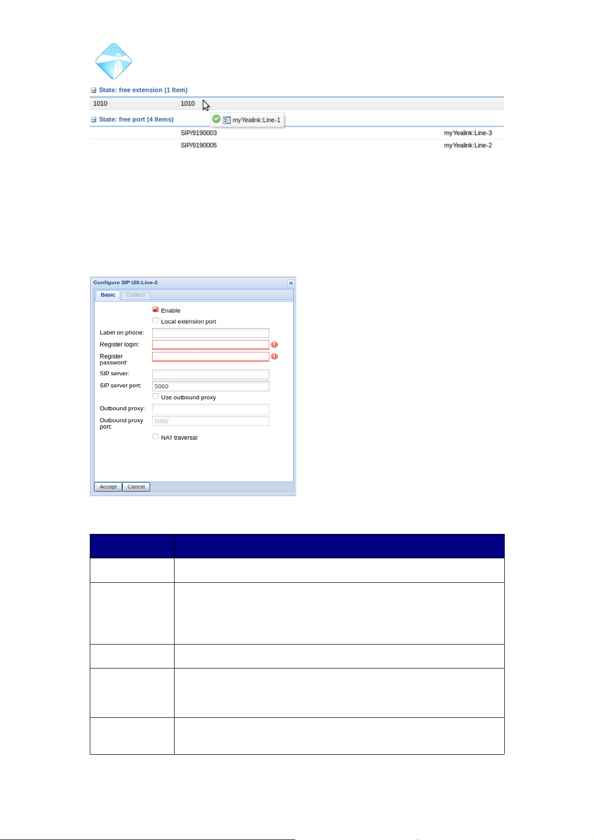
Com.X Administrator Guide
Page 83
3.5.5.5 Configuring a port on the Phone to register as an extension on a remote system
If there is an unused port(line) on the handset, you can configure it to register as an
extension on a remote PBX, from the Com.X GUI.
Navigate to the hardware page and select the port from the port tree. Right-click and
select Edit.
FIELD DESCRIPTION
Enable If not ticked, the line will not be available for configuration.
Local Extension
Port
If enabled, SIP Server, Register Login and Register Password
fields will be automatically populated. Disable this option to
manually enter configuration details and register an extension on a
remote system.
Label on Phone Enter the label you would like to see on the phones display.
Register Login If Local Extension Port is disabled, this field can be edited to
contain the authorisation name for an extension on a remote
system.
Register
Password
If Local Extension Port is disabled, this field can be edited to
contain the password for an extension registering on a remote
©2010 – 2016 Far South Networks
Figure 84: Click and drag the desired line over the desired free extension. Note the
green tick icon on the line being dragged.
Figure 85: Editing a line on a Managed Sip
Phone.
Page 84
Com.X Administrator Guide
Page 84
system.
SIP Server If Local Extension Port is disabled, this field can be edited to
contain the IP address of the remote SIP server on which the
extension is registering.
SIP Server Port If Local Extension Port is disabled, this field can be edited to
contain the port on which the extension should register on the
remote system.
Use Outbound
Proxy
If enabled, an outbound proxy can be configured through which to
register the extension.
Outbound proxy The address of the outbound proxy through which the extension
registers with the remote system.
Outbound
Proxy port
The port of the outbound proxy through which the extension
registers on the remote system.
NAT Traversal If enabled, the phone will use NAT to locate its remote host.
Note: In order for a line on a managed Sip phone to register as an extension on a
remote system, correct routing needs to be configured on both systems. This would
require a route to allow the phone to connect to the external network through the
correct interface, and a corresponding route on the remote system, directing traffic
to the phone to the correct interface.
3.5.6 Codecs
By default extensions created in the above manner, will be configured to support an
alaw codec. To add or remove supported codecs to the extension, right-click the
extension and select “Edit”. Select the “Codecs” tab. This will present a list of
available Codecs. To select multiple Codecs, hold “Ctrl” and click on the desired
Codecs.
©2010 – 2016 Far South Networks
Page 85
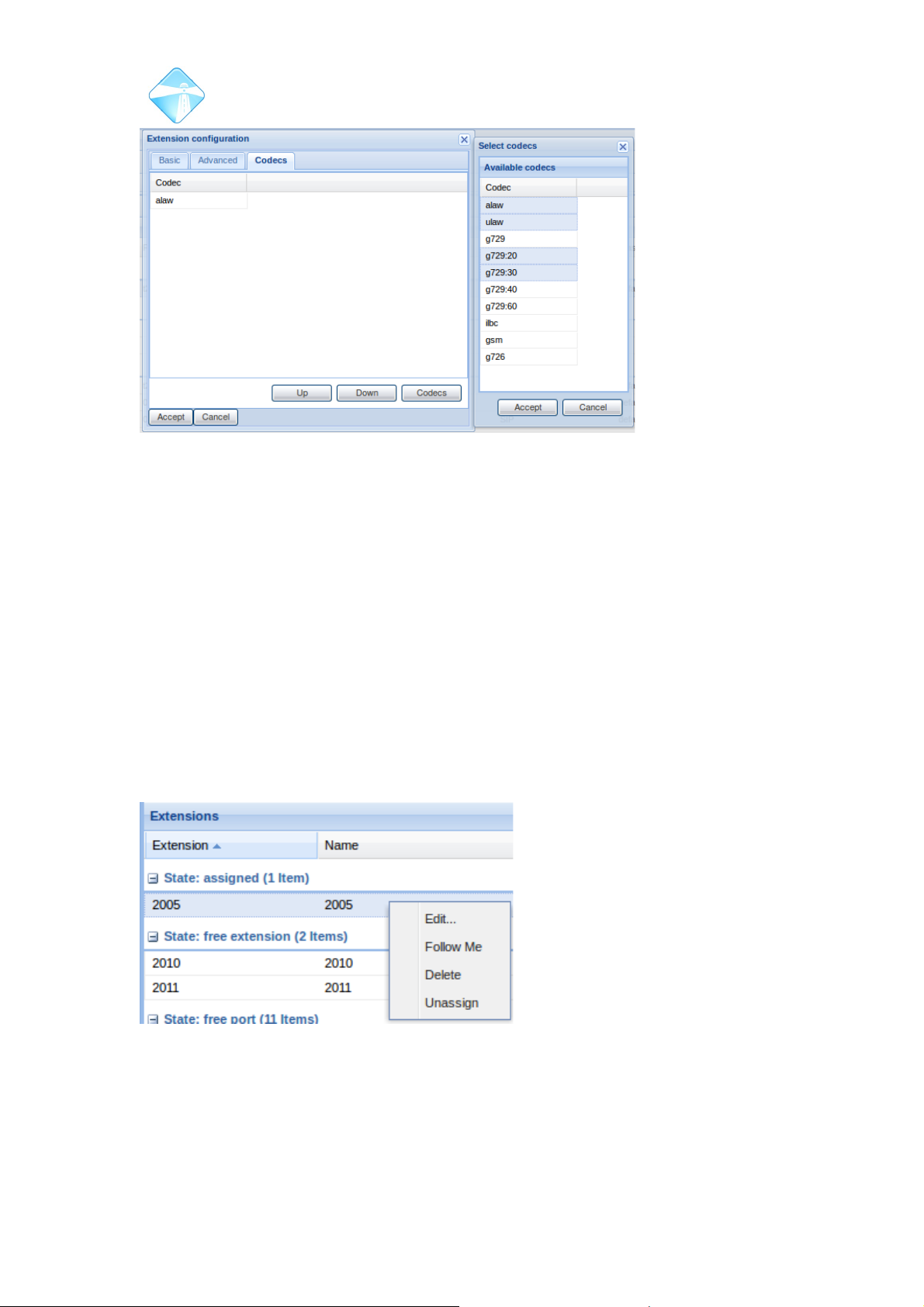
Com.X Administrator Guide
Page 85
3.5.7 Removing an association to an extension
Two possibilities exist for removing extensions from device lines.
3.5.7.1 Unassigning Extensions
To unassign an extension, right-click on the extension in the extensions list and
select Unassign. This will result in the phones line becoming a free port and the
extension becoming a free extension. The extension will remain in any inbound
routes,destinations (queues and ring groups) and flex-path contexts and can be
logged in to from any free port by dialling the *11 feature code (See section 3.7.5 )
3.5.7.2 Deleting Extensions
To delete an extension, right-click on the extension in the extensions list and select
Delete. This will result in the line on the phone becoming a free port, and the
extension being deleted. The extension will be removed from any inbound routes,
queues, ring groups, flexpaths and other internal destinations.
3.5.8 Advanced Configuration options for Managed SIP Devices
The advanced configuration options can be configured by right-clicking the Managed
SIP Device entry on the hardware panel and selecting 'Advanced'.
©2010 – 2016 Far South Networks
Figure 86: Extensions can be configured to support multiple
Codecs.
Illustration 2: Deleting or Unassigning an
extension will result in a free port on the phone.
Page 86
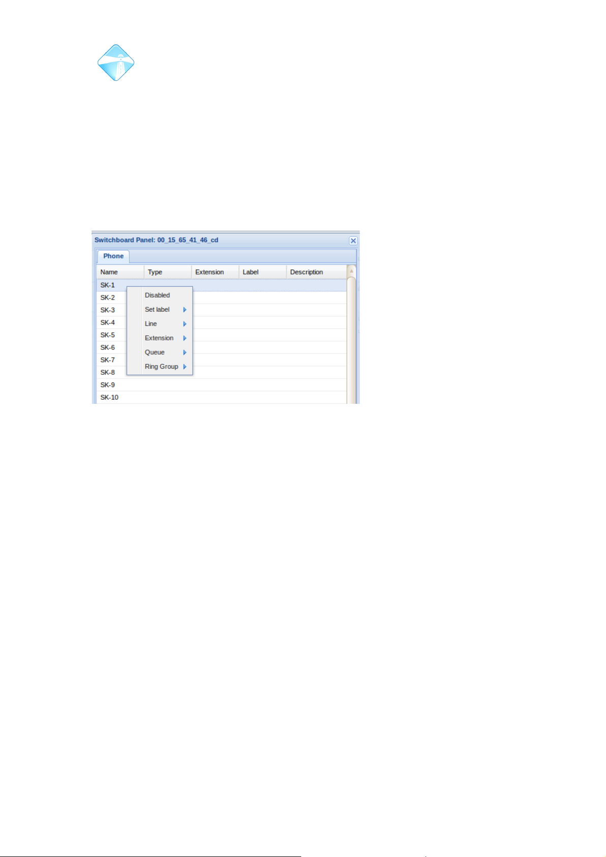
Com.X Administrator Guide
Page 86
3.5.8.1 Configuring Soft Keys
The Com.X GUI offers a mechanism to provision the soft keys keys of compatible
handsets. These keys can be set to transfer to, and monitor the status (through BLF)
of : other extensions, conference extensions, queues, ring groups, parking lots and
particular parking bays within parking lots.
3.5.8.2 Configuring keys individually
Right click the device and navigate to Advanced ->Switchboard.
Using this interface, the keys of the handset, as well as any extension modules to
which it is connected,can be configured directly from the GUI.
Right-click the particular key you wish to edit, and select a destination.
If the user of the managed SIP Device is on a call, pushing the key will transfer the
call to that destination. If no call is in progress, pressing the key will initiate a call to
the destination.
By default, the DSS key will also show the status of the destination through the Busy
Lamp Field. If the destination is available, the lamp next to the DSS key will be green.
If the destination is busy, the lamp will be red and if the extension is ringing, the light
will flash red.
3.5.8.3 Configuring Multiple DSS keys to map to consecutive extensions.
It is possible to simultaneously configure multiple keys to map to extensions. Rightclick the Managed SIP Device in the hardware list. Navigate to Advanced>Switchboard and then select multiple soft keys by left clicking the first key you
would like to edit and then holding shift while left clicking the last key in the range. To
select non-consecutive keys, hold Ctrl while selecting the desired keys.
©2010 – 2016 Far South Networks
Figure 87: Available destinations for soft keys include
extensions,conferences,queues,ring groups, parking
lots and individual parking bays.
Page 87
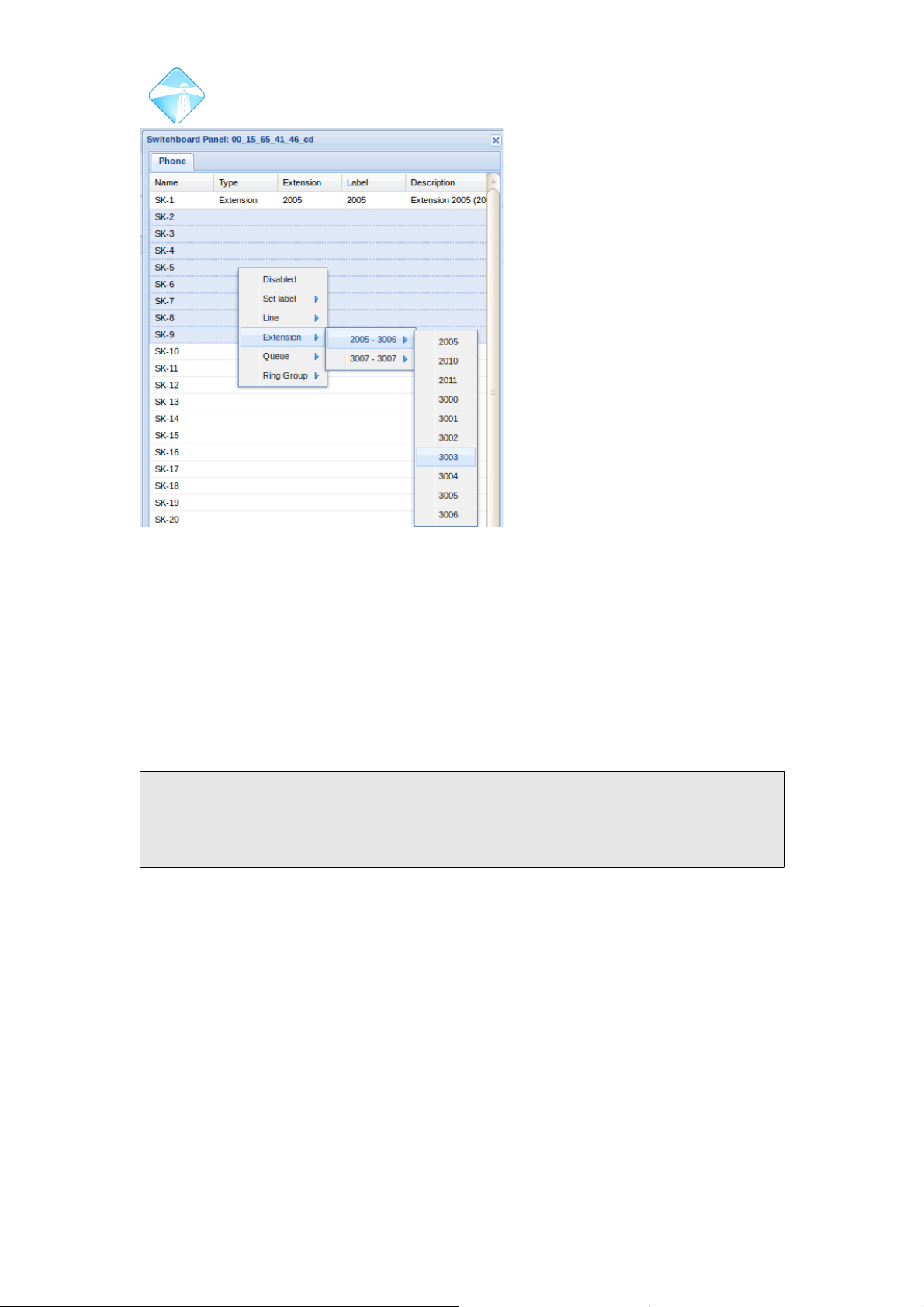
Com.X Administrator Guide
Page 87
Select the Extension option and choose the first extension in the range. The first
highlighted key will then be set to the first extension selected and the subsequent
keys set to the next extensions featured in the list.
3.5.8.4 Adding an Extension Module
To add an extension module, simply click “Add”. Navigate to the correct EXT tab to
configure the soft keys of the extension module. Multiple extension modules can be
added to handsets that support them.
The EXT keys are configured as per section 3.5.8.1.
Note: Applying any changes to Managed SIP Devices from the Com.X GUI will
cause the handset to reboot. The device will reboot,and then update configuration
upon startup. This process results in the phone being unavailable for around one
minute after a Review/Apply.
3.6 Configuring Comma device ports
When a device is selected in the device list, the available ports on the device are
categorized and listed in the ports tree on the right of the Hardware panel. Comma
ports are enumerated using the device's name, the card index in the device and the
port number. I.e. device:a2-5 would indicate the fifth port on the second analogue
card (a – analogue, d – bri, p – pri) in a device called 'device'.
3.6.1 Configuring Analogue Trunk (FXO) ports
To edit the configuration of an FXO port, double-click on the desired port from the
ports tree on the right of the hardware panel.
©2010 – 2016 Far South Networks
Figure 88: Multiple DSS keys can be configured
to transfer to consecutive extensions
Page 88

Com.X Administrator Guide
Page 88
Field Content
Input gain Indicates how much, if any, gain adjustment should be performed
in the input direction. Values are in decibels.
Output gain Indicates how much, if any, gain adjustment should be performed
in the output direction. Values are in decibels.
Echo canceler The echo cancellation delay and algorithm to be employed on the
port. The delay up to which the echo canceler can compensate is
specified in milli-seconds. An optional non-linear processing
echo suppression algorithm (NLP) can also be employed during
echo cancellation. If you expect the devices connected to the port
to be in a noisy environment how-ever, you might prefer not to
enable NLP, as it might result in the far-end noise being cut off
when speech ceases. Some local users may find this
uncomfortable. NLP is recommended for quiet remote
environments. Please see section 3.6.8.1 for a detailed
discussion around echo cancellation.
Detect Fax When enabled, the Com .X will differentiate between an incoming
call and an incoming fax. Any echo cancellation configurations
will be bypassed and the jitter buffer for the call adjusted for a
higher tolerance, in the event of an incoming fax.
DID number A direct inward dialing number to associate with this port. A call
incoming on this port may be routed using the DID.
DID description A custom description for the DID.
Detect caller ID If this is enabled, the incoming caller ID, if available, will be
detected and may be used in inbound routing.
Hangup
detection
Devices such as Least Cost Routers connected to FXO ports, or
the Telco equipment in various parts of various countries may
signal hangup differently. Change this setting to match the tone
set for the country of device deployment, or the duty cycle of the
hangup signal you are receiving. Options include 250, 500 or
2500 ms of tone followed by the same period of silence and any
regular pattern.
Note: if a country tone-set is not available for the country of
deployment and as a result on of the available duty cycles is
configured, it is possible that different exchanges routing
inbound calls to the system might have different end-of-call
tones.
This may result in FXO port lockup if the varying tones cannot
be detected using the configured duty cycle. If this is the case,
use the 'Any regular pattern' setting to detect such tones.
For more information on the options available to detect end-ofcall under such conditions, please see the Com.X Troubleshooting guide.
©2010 – 2016 Far South Networks
Page 89

Com.X Administrator Guide
Page 89
Table 6: FXO port configuration
3.6.2 Configuring Analogue Extension (FXS) ports
Field Content
Input gain Indicates how much, if any, gain adjustment should be performed
in the input direction. Values are in decibels.
Output gain Indicates how much, if any, gain adjustment should be performed
in the output direction. Values are in decibels.
Echo canceller The echo cancellation delay and algorithm to be employed on the
port. The delay up to which the echo canceler can compensate is
specified in milli-seconds. An optional non-linear processing
echo suppression algorithm (NLP) can also be employed during
echo cancellation. If you expect the devices connected to the port
to be in a noisy environment how-ever, you might prefer not to
enable NLP, as it might result in the near-end noise being cut off
when speech ceases. Some remote users may find this
uncomfortable. NLP is recommended for quiet local
environments. Please see section 3.6.8.1 for a detailed
discussion around echo cancellation.
Allow transfer If enabled, the phone using this port is allowed to transfer calls.
Immediate mode When enabled, ring tone is not provided when the phone goes off
hook and the Com.X is required to take immediate action, such
as dialing an emergency number. Please see section 3.12.11.7
for more detail on using FlexPath with his feature.
Fax channel Indicates that this port is to be used for fax. Enabling this setting
disables echo cancellation on the port. Please see section 3.6.8
Table 7: FXS port configuration
3.6.3 Configuring BRI ports
Field Content
Link Type Indicates whether this device is part of a point-to-point (i.e. DIDs
may be issued by the telco) or point-to-multipoint (i.e. one or
more multi-subscriber numbers may be issued, or multiple BRI
devices share the BRI bus.) The link type needs to match the
mode of the service provided by the telco.
Act as NT When disabled, the device is an ISDN TE, connected to the telco
NT. When enabled, this port acts as though it is an ISDN NT
device. This is useful when the Comma device is placed between
the PBX and the telco NT, e.g. for least-cost routing and BRI
gateway routing.
Bus termination Comma BRI cards have terminating resistors on-board, removing
the need for external terminators. If this device should terminate
©2010 – 2016 Far South Networks
Page 90

Com.X Administrator Guide
Page 90
Field Content
the BRI bus (this is the usual case), enable this setting.
If multiple devices are attached to the BRI cable (point-tomultipoint) and another device is providing termination, the
Com.X can be configured not to terminate.
A BRI link should always be terminated by a device on at least
one side of the BRI connection, or electrical reflection on the link
could interfere with BRI signaling and result in loss of layer 1 link
establishment, or CRC errors.
Echo canceler The echo cancellation delay and algorithm to be employed on the
port. The delay up to which the echo canceler can compensate is
specified in milli-seconds. An optional non-linear processing
echo suppression algorithm (NLP) can also be employed during
echo cancellation. If you expect the devices connected to the port
to be in a noisy environment how-ever, you might prefer not to
enable NLP, as it might result in the far-end noise being cut off
when speech ceases. Some local users may find this
uncomfortable. NLP is recommended for quiet remote
environments. Please see section 3.6.8.1 for a detailed
discussion around echo cancellation.
Note: This setting applies to all BRI ports in the same BRI trunk
group as this BRI port. This option is not available if the port is
not part of at least one BRI trunk group.
Detect Fax When enabled, all BRI ports in all trunk groups to which this BRI
port belongs will detect fax tones and disable echo cancellation
for the duration of a fax call. We recommend enabling this feature
on all BRI ports that are likely to support fax calls.
Note: This option is not available if the port is not part of at least
one BRI trunk group.
Table 8: BRI port configuration
3.6.4 Configuring PRI
Field Content
Physical interface The service offering, either 23B+D T1 or 30B+D E1. For E1,
double frame or CRC4 multi-frame can be enabled, and for T1
framing can be either Super Frame (D4) or Extended Super
Frame (ESF, using CRC-6) The physical interface configuration
must match that of the PRI peer.
Switch type National switch type options are:
US National ISDN phase 1 (NI-1)
US National ISDN phase 2 (NI-2)
ETSI “Euro” ISDN: Europe ISDN standard
©2010 – 2016 Far South Networks
Page 91
Com.X Administrator Guide
Page 91
Field Content
QSIG: protocol for switching between PBXs
Signaling role When configured as Terminal, the device is an ISDN TE,
connected to the telco NT. When configured as Network, this
port acts as though it is an ISDN NT device. This is useful when
the Comma device is placed between the PBX and the telco NT,
e.g. for least-cost routing.
Overlap dialing Enabling this setting will result in digits being transmitted across
the PRI link as they are dialed, as opposed to the full number
being collected before dialing. Overlap dialing allows a
destination number to be specified partially resulting in the first
stage of a routing path being established before the remaining
digits arrive.
Table 9: PRI port configuration
3.6.5 Removing devices
To remove a device configuration, select Remove from the device's context menu.
Note: Any of the device's ports that are included in trunk groups will be removed
from the groups, outbound routes that make use of the ports will no longer be
associated with the ports and any extensions associated with device ports or
channels will become unassigned.
3.6.6 Echo cancellation
When two phones, B and C are in a call, and the person's speech at phone C is
reproduced at phone B, some of the audio exiting B's earpiece re-enters B's
microphone and is returned as echo. Analog lines exacerbate this problem due to
additional reflection of audio in the electronic circuitry. The result of audio feedback at
B is that person C hears his/her own voice after a short delay i.e. echo occurs.
The person hearing the echo should look to the remote party for the cause of the
echo and not to their own phone and system. If both parties experience echo, both
systems should be investigated.
In analog phones, both the 2-wire to 4-wire converter (hybrid) and the handset can
introduce echo. The Com.X impedance parameters are aligned with South African
telecommunications standards. Non-compliant handsets with a large impedance
mismatch are likely to introduce noticeable echo. The delay introduced by VoIP
based systems can result in the returned echo becoming noticeable to the person
who is speaking.
The degree of echo and the delay between the original audio and the echo is a
function of the handset, gain settings, potential wiring problems and the audio
transmission path.
The Com.X products incorporate a sophisticated Echo Canceller for each telephony
channel (BRI, PRI or analog). The algorithm adapts to the detected audio feedback
within a configurable timeframe of 16, 32 or 64 milliseconds, and attempts to create
an identical image of the echo, which is then removed from the audio signal prior to
©2010 – 2016 Far South Networks
Page 92

Com.X Administrator Guide
Page 92
sending it on to the other party. Generally, a shorter timeframe is preferable since it
reduces the time the algorithm takes to “learn” the feedback environment. Typically,
echo is reduced to below detectable levels within 1 – 2 seconds. In extreme cases
convergence might take 3 – 12 seconds, during which call quality would increase to
an optimum.
After primary echo has been canceled in this way, some residual echo may remain
(echo present beyond the time-frame the canceler buffered or “non-linear”
reflections). Such echo is then removed by a non-linear echo cancellation algorithm,
if enabled. This may result in one of the parties' audio being clipped when both
parties are talking. Some users may find this uncomfortable. If this is the case it
might be preferable to disable the NLP.
Although the default (16ms + NLP) is normally a good compromise, the Echo
Cancellation settings may need to be adjusted on a per-port basis, as the audio
environment might differ from one port to the next (e.g. an office environment for one
range of extensions vs a factory floor for another and an open plan arrangement for
another range of extensions.)
Wiring problems, such as power cables crossing telephone cables, or insufficient
earthing of the Com.X or iTAs may add noise to the audio path that may reduce
performance of the algorithm.
In diagnosing echo cancellation problems, establish good earth (~0.5 ohm or less, if
resistance approaches 1 ohm earthing might be a concern), and proceed to eliminate
each of the potential contributing elements from the equation by testing with different
phones, connecting phones directly to the Com.X FXS ports, turning echo
cancellation off completely to establish a quality baseline and then trying different
combinations of echo cancellation, with and without NLP, on the different extensions.
Often the first measure to attempt, often yielding the greatest improvement is to try
adjusting the gain on problematic extensions.
Note: In exceptional circumstances, if the echo cancelers take a long time to
converge (e.g. > 10 seconds), the acoustics of the environment might be introducing
too much echo, long loops may be present in the telco network and / or the handset
might be too sensitive.
Adjusting the gain on the port down might help, or fixing the FIR coefficients in the
echo canceler for that port might help. After restart, the first call on ports configured
thus would take a long time to converge, and there-after the coefficients are re-used
for subsequent calls. Due to the dynamic nature of echo, fixing the coefficients is not
recommended for most cases.
To fix the coefficients select the 'Keep' option on the FXO/FXS port.
Following this, restart the iTA for the new settings to take effect with:
comma-ls -r
Please note that echo heard by users of the Com.X (as opposed to external parties)
is typically caused by the remote party. The Com.X does attempt to cancel the echo
from the remote party on BRI, PRI and FXO connections to the telco, but the
effectiveness of this cancellation is highly dependent on external conditions which
are impossible to predict or control.
©2010 – 2016 Far South Networks
Page 93
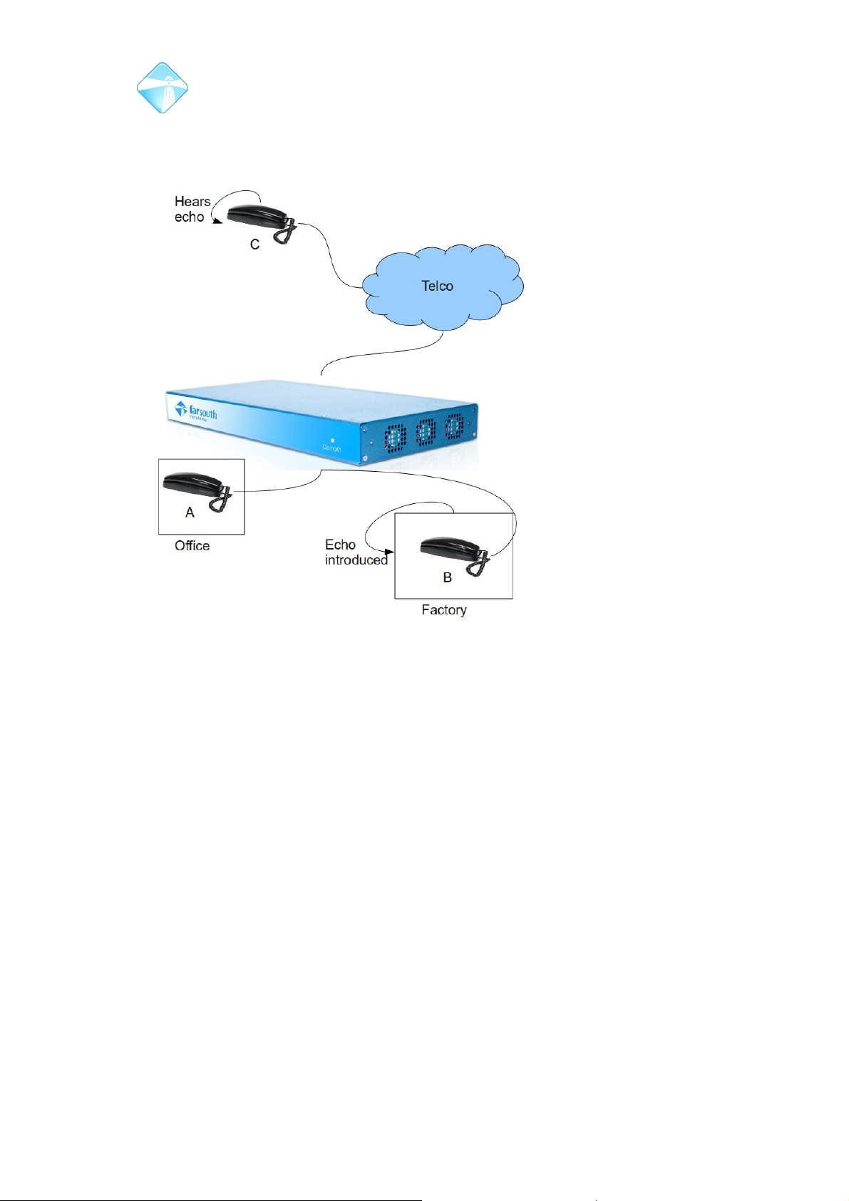
Com.X Administrator Guide
Page 93
Note also that SIP connections (including local SIP phones) are never echo
cancelled (it is not technically feasible) – therfore, this is the responsibility of the SIP
phone itself or of the upstream service provider.
3.6.7 Earthing the Com.X
Proper earth with < 0.5 ohm measured from the Com.X stud to the earthing point,
preferably to telco or failing that, building earth should be present on all installations.
The Com.X provides an earth connection in its power brick and cable. If a good
mains earth is present, a separate earth strap to the Com.X earth stud could be
unnecessary.
The Comma iTA (if present) does not have an earth connection in its power brick and
must be earthed using an earth strap and its earth stud.
It is important that Com.X and iTA devices are earthed in a “star” pattern to a single
earthing point. Do not wire an iTA to a Com.X's earth stud or vice versa.
Be careful not to create earth loops which may induce noise into the system. Ensure
high quality multi-adapters (multi-plugs) are employed, and do not place the Com.X
at the end of a chain of devices chained on the same multi-adapter.
3.6.8 Configuring devices for Fax / modem support
3.6.8.1 Echo cancellation
Echo cancellation plays an important part in ensuring voice quality through the
telecommunications network.
©2010 – 2016 Far South Networks
Figure 89: Echo cancellation
Page 94

Com.X Administrator Guide
Page 94
The Com.X product range incorporates state of the art, innovative, embedded onDSP-chip echo cancellation that off-loads resources from the system server.
Echo cancellation can how-ever affect fax and modem signaling and data. It is
therefore important to understand the impact of echo cancellation on fax and modem
negotiation and configure devices correctly for fax use.
Echo cancellation is performed at the source device, where 'source' here indicates a
network endpoint that introduces a signal into the PBX system. In the Com.X
systems echo cancellation takes place on FXO, BRI and PRI ports/channels
terminating traffic from the PSTN for routing in the system, as well as FXS ports
originating calls via the PBX.
If not configured properly for fax support, faxes and modems may fail or higher baud
rate operation might not be possible.
At these sources, if a fax start “CNG” tone is detected and the port / channels are
correctly configured for fax, the echo cancelers are automatically disabled, and a
clear channel is offered for fax service.
In the case of PRI and BRI channels, channels may serve both voice and fax traffic,
and detection of the fax tone is required before echo cancellation can be switched
off. This detection is configurable from the Hardware panel for BRI trunk groups and
PRI ports.
Since fax devices are usually affixed to individual ports, and specific incoming DIDs
reserved for fax use, in the case of FXS and FXO, ports need to be deliberately
reserved for fax use by disabling echo cancellation. This is done for FXO ports by
enabling the “Detect Fax” option, and for FXS ports by enabling the “Fax channel”
option in the hardware panel, which disables echo cancellation and configures
additional jitter buffering for the port.
3.6.8.2 Telco issues
Telco FXO connectivity, cable distance and environment, etc. introduces additional
signal to noise ratio and impedance elements into the equation and may not support
high baud rates.
3.6.8.3 Timing
Timing in the system is very important to ensure successful fax / modem
communication. The iTA device (e.g. the internal BRI / PRI enabled iTA MPC card in
the Com.X1 case or the BRI / PRI iTA in the Com.X2 case) connected to the telco
interface should have the highest timing priority (line N), and other iTAs connected
should derive timing from this device (system). Please see section 3.4.5.1 for detail
on configuring the timing source on an iTA device.
In scenarios where multiple PRI links are configured to the same telco, setting the
first PRI as PRI Line 1 is recommended (i.e. deriving clocking from the telco line) and
setting all other PRIs to System (i.e. sharing the clocking of the first PRI in the
transmit direction and honoring the telco's clocking on each PRI in the receive
direction.
In gateway scenarios, where one or more PRIs face the telco and one or more PRIs
face a 3rd party device, the telco-facing PRIs should be configured as above, and the
PRIs facing the 3rd party device should be configured to use System timing. In this
scenario the “transmit clocking” setting should be enabled the relevant PRI ports in
the GUI hardware panel.
©2010 – 2016 Far South Networks
Page 95

Com.X Administrator Guide
Page 95
This indicates to the Com.X that the receive direction clocking (from the 3rd party
device) should not be honored (as in the telco case), but that the Com.X should
propagate its system-derived timing to the 3rd party device. In such configurations the
3rd party device should be configured as a clock slave.
This additional configuration is not required for BRI ports, as the NT/TE mode setting
on BRI pre-selects the correct timing driver on the gateway leg facing the 3rd party
device. BRI timing configuration follows the same Line Priority and System
configuration pattern as described above for PRI.
If an iTA is connected to a switch located between the iTA and the Com.X host
server, network packet delays could occur which could also affect timing. If this is the
case, from the GUI, Monitor – Telephony – dahdi statistics should show slips and
skips increasing on the span to the iTA. The Com.X can be instructed to buffer in the
receive direction from the iTA in order to alleviate such network delays. This is done
by enabling the “Network slip tolerant” setting on the GUI under Setup – Global
Settings.
Please also refer to the Com.X troubleshooting guide for more information on fax and
modem troubleshooting.
3.6.8.4 Additional configuration for faxing over PRI
In order to enable clear-channel communication for fax over PRI, the PRI needs to be
configured to allow fax detection and the disabling of echo cancellation on fax calls.
This is performed by enabling the “Fax detect” setting on the PRI port in the
hardware panel.
3.6.8.5 Fax over IP
Com.X systems support t.38 faxing and g711 bypass on SIP trunks. With G.711
bypass, the trunk is configured for a compressed codec (e.g. G.729) as well as
G.711 A-law. The upstream gateway re-invites on detecting the fax tone, excluding
the G.729 from the allowed codecs. The Com.X switches to the A-law codec,
allowing clear channel fax transmission.
3.6.8.5.1 G.711 voice band data (ITU-T V.152)
Com.X features that support voice band data for fax over IP are:
• Automatic G.711 bypass for fax (see above)
• The default configuration of Com.X SIP is constant latency (i.e. fixed jitter
buffer)
• Fax detection with automatic echo canceller disable is supported on
analog/ISDN channels where echo cancellation may impair the fax signal
• The A-law codec does not use DC removal filters
• Com.X VoIP does not use Comfort Noise Generation or Voice Activity
Detection
• The SDP negotiation extensions (V.152 clause 7.1) are not supported in
Com.X. However, a switch to G.711 A-law on re-invite accomplishes the clear
channel requirement for voice band data, as described above.
©2010 – 2016 Far South Networks
Page 96

Com.X Administrator Guide
Page 96
3.7 Extension configuration
3.7.1 Extensions and Extension Ports
The Com.X treats extensions and extension ports differently.
• Extensions represent dialable numbers (users) in the system, e.g. extension
1000.
• Extension Ports represent hardware devices available for making and
receiving calls, e.g. FXS lines (analog phone) and SIP phone lines.
Note that a SIP phone may have more than one line and hence more than one
extension port.
Extension Ports are created when Comma or Managed SIP devices are added in the
Hardware Panel, and when Generic SIP extensions are added in the Extension
Panel.
An Extension and an Extension Port can be associated, either by configuration as
described below or by “hot-desking” user login.
3.7.2 Listing existing extensions and ports
To manage the list of configured extensions, select Start, followed by Configuration
and the Extensions panel.
Configured extensions are categorized as those having been assigned to extension
ports, and those that are unassigned (free extensions). Free extension ports are also
listed. These ports are available for either fixed extension assignment or for dynamic
extension login (hot-desking).
For each extension, the number, friendly name, pickup group, port assignment, port
secret, extension type (analogue or SIP), class of service and voicemail indicator are
displayed.
At the right of the extensions panel, available FXS and SIP extension ports are
shown, with current extension number assignments to these ports appended in
square brackets.
3.7.3 Adding Extensions
Extensions can be added either by selecting extension ports in the ports list and
right-clicking to assign extensions to the ports (select multiple ports for assignment
using CTRL-click), by dragging a port from the tree on the right onto a free extension,
or by using the Add button on the Extension panel to add free or generic SIP
extensions. Individual extensions, or a range of extensions can be added.
©2010 – 2016 Far South Networks
Page 97
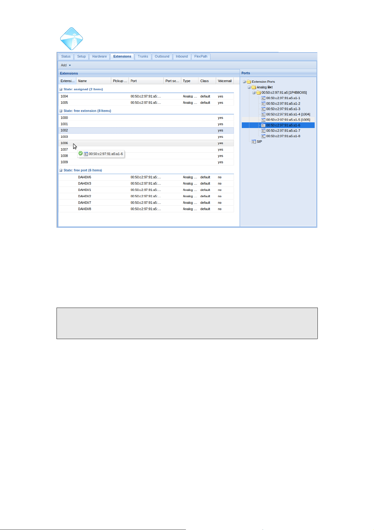
Com.X Administrator Guide
Page 97
3.7.3.1 Adding extensions from ports
Single extensions or a group of extensions can be assigned to available extension
ports by selecting the ports in the ports list and selecting Assign from the context
menu.
A starting extension number can be specified, and upon acceptance extensions are
numbered incrementally from the starting number for the number of extensions
selected.
Note: The end of the range is not specified, instead the number of extensions
desired is specified. If a large range is entered, the GUI will present a warning to the
user.
3.7.3.2 Adding Unassigned extensions
When a range of extensions is added, the friendly name is set equal to the extension
number.
3.7.3.3 Adding Generic SIP extensions
A Generic SIP extension allows local or remote login of any standards based SIP
phone or softphone.
When a Generic SIP extension is created, both an Extension and an Extension Port
are created with the same name, and automatically associated together. In this case,
there is no device element related to the Extension Port.
The following password generation schemes are supported for SIP extensions:
•Fixed: The same password is set for all the newly created extensions. A new
strong, random password of length 12 is suggested by default.
©2010 – 2016 Far South Networks
Figure 90: Assigning extensions
Page 98
Com.X Administrator Guide
Page 98
•Same as Extension: The password for each newly created extension is the same
as the extension number.
Note: setting the extension password to the extension number is strongly
discouraged and may lead to weak system security!
•Random: A strong unique, random password of length 12 is generated , for each
newly created extension.
3.7.4 Configuring extensions
3.7.4.1 Basic configuration
Field Content
Number The extension number selected during creation. This cannot be
changed after extension creation.
Friendly name A custom name for the extension
Port The device and port the extension has been assigned to, if any.
This can only be changed by unassigning and re-assigning the
extension (please see 3.7.9 and 3.7.8)
Table 10: Extension configuration
©2010 – 2016 Far South Networks
Page 99

Com.X Administrator Guide
Page 99
3.7.4.2 Advanced configuration
©2010 – 2016 Far South Networks
Page 100

Com.X Administrator Guide
Page 100
Field Content
Voicemail Enable this to enable voicemail for the extension.
Note: Disabling voicemail will reset any call recording settings
that may have been configured on the extension!
Pin The user pin used to access voicemail and features
Email An email address to which voicemail will be emailed
Call waiting Enables the call waiting feature, allowing an indication to be
provided to the user when an incoming call arrives while the user
is on the phone
Campon Callback If enabled, an automatic callback feature will be offered to local
users who call to this extension whilst it is unavailable,
Call Recording Use this field to select the call recording behaviour of this
extension.
• Enabled: Inbound and outbound calls will all be recorded.
• Disabled: No calls will be recorded.
• On Demand: Calls will record only when the user dials *1
in call.
• Inbound Only: Only calls that extension receives will be
recorded, but not calls which it initiates.
• Outbound Only: Calls initiated by the extension will be
recorded. All other calls will not be recorded.
Ring time The number of seconds to ring before activating voicemail. This
setting is ignored if voicemail is not configured, or follow-me is
active
Pickup group Assign this extension to a pick-up group, allowing other
members of the pick-up group to pick up this extension when it
rings using a specified feature code (*8). Specify multiple pickup
groups using “,” E.g. “1,2,3” In order to allow an extension to be
picked up using directed pickup (**) from any group, enter a * in
this field.
Account code The account code to be recorded in the CDR record for calls
placed by the extension.
Note: FlexPath account code or outbound trunk CID override
configuration may supersede the value configured here.
Secret Password used to authenticate the extension. Only visible and
configurable on SIP extensions.
©2010 – 2016 Far South Networks
 Loading...