

Page 1
FARO LASER SCANNER USER MANUAL
For more information contact Synergy Positioning Systems or
visit the Synergy Positioning Systems website at www.synergypositioning.co.nz
All branches: Phone 0800 867 266 Email: [email protected]
SEPTEMBER 2017
Page 2

Release Notice
October 23, 2017
This is the September 2017 version of the FARO
®
Laser Scanner User Manual.
©FARO Technologies Inc., 2017. All rights reserved.
No part of this publication can be reproduced, or transmitted in any form or by any means without written
permission of FARO Technologies, Inc.
FARO TECHNOLOGIES, INC. MAKES NO WARRANTY, EITHER EXPRESS OR IMPLIED,
INCLUDING BUT NOT LIMITED TO ANY IMPLIED WARRANTIES OF MERCHANTABILITY OR
FITNESS FOR A PARTICULAR PURPOSE, REGARDING THE FAROARM, FARO GAGE, FARO
LASER TRACKER, FARO LASER SCANNER, FARO IMAGER AND ANY MATERIALS, AND MAKES
SUCH MATERIALS AVAILABLE SOLELY ON AN “AS-IS” BASIS.
IN NO EVENT SHALL FARO TECHNOLOGIES, INC. BE LIABLE TO ANYONE FOR SPECIAL,
COLLATERAL, INCIDENTAL, OR CONSEQUENTIAL DAMAGES IN CONNECTION WITH OR
ARISING OUT OF THE PURCHASE OR USE OF THE FAROARM, FARO LASER TRACKER, FARO
IMAGER OR ITS MATERIALS. THE SOLE AND EXCLUSIVE LIABILITY TO FARO TECHNOLOGIES,
INC., REGARDLESS OF THE FORM OF ACTION, SHALL NOT EXCEED THE PURCHASE PRICE OF
THE MATERIALS DESCRIBED HEREIN.
THE INFORMATION CONTAINED IN THIS MANUAL IS SUBJECT TO CHANGE WITHOUT NOTICE
AND DOES NOT REPRESENT A COMMITMENT ON THE PART OF FARO TECHNOLOGIES INC.
ACCEPTANCE OF THIS DOCUMENT BY THE CUSTOMER CONSTITUTES ACKNOWLEDGMENT
THAT IF ANY INCONSISTENCY EXISTS BETWEEN THE ENGLISH AND NON-ENGLISH VERSIONS,
THE ENGLISH VERSION TAKES PRECEDENCE.
The FARO
®
Laser Scanner is protected by U.S. patent 7,869,005.
Trademarks
FARO, FARO Laser Scanner, and FARO Scanner Freestyle
Objects are registered trademarks or
trademarks of FARO Technologies Inc. All other brand and product names are trademarks or registered
trademarks of their respective companies.
Microsoft, Internet Explorer, Windows, Windows 7 and Windows 8 are either registered trademarks or
trademarks of Microsoft Corporation in the United States and/or other countries.
Adobe and Flash are either registered trademarks or trademarks of Adobe Systems Incorporated in the
United States and/or other countries.
Gitzo is a registered trademark of Gitzo Sa.
Page 3

FARO®Laser Scanner Manual
Table of Contents
Chapter 1: General Information
1.1 Notes and Signs. . . . . . . . . . . . . . . . . . . . . . . . . . . . . . . . . . . . . . . . . . . . . . . . . . . . . . . . . . . . . . . . . 2
Chapter 2: Introduction
Chapter 3: Equipment
Chapter 4: Safety Precautions
4.1 Intended Use. . . . . . . . . . . . . . . . . . . . . . . . . . . . . . . . . . . . . . . . . . . . . . . . . . . . . . . . . . . . . . . . . . 10
4.2 Improper Use. . . . . . . . . . . . . . . . . . . . . . . . . . . . . . . . . . . . . . . . . . . . . . . . . . . . . . . . . . . . . . . . . . 10
4.3 Users . . . . . . . . . . . . . . . . . . . . . . . . . . . . . . . . . . . . . . . . . . . . . . . . . . . . . . . . . . . . . . . . . . . . . . . . . 10
4.4 General Safety Information. . . . . . . . . . . . . . . . . . . . . . . . . . . . . . . . . . . . . . . . . . . . . . . . . . . . . . 10
4.5 Electrical Safety . . . . . . . . . . . . . . . . . . . . . . . . . . . . . . . . . . . . . . . . . . . . . . . . . . . . . . . . . . . . . . . 11
4.5.1 Power Block Battery Safety Measures . . . . . . . . . . . . . . . . . . . . . . . . . . . . . . . . . . . . . . . . 12
4.5.2 Power Dock Battery Charger Safety Measures. . . . . . . . . . . . . . . . . . . . . . . . . . . . . . . . . 12
4.6 Mechanical Safety. . . . . . . . . . . . . . . . . . . . . . . . . . . . . . . . . . . . . . . . . . . . . . . . . . . . . . . . . . . . . 13
4.7 Transport . . . . . . . . . . . . . . . . . . . . . . . . . . . . . . . . . . . . . . . . . . . . . . . . . . . . . . . . . . . . . . . . . . . . . 13
4.8 Storage. . . . . . . . . . . . . . . . . . . . . . . . . . . . . . . . . . . . . . . . . . . . . . . . . . . . . . . . . . . . . . . . . . . . . . . 14
4.9 Servicing. . . . . . . . . . . . . . . . . . . . . . . . . . . . . . . . . . . . . . . . . . . . . . . . . . . . . . . . . . . . . . . . . . . . . . 14
Chapter 5: Parts and their Functions
5.1 Scanner Parts . . . . . . . . . . . . . . . . . . . . . . . . . . . . . . . . . . . . . . . . . . . . . . . . . . . . . . . . . . . . . . . . . 16
5.1.1 Display Side . . . . . . . . . . . . . . . . . . . . . . . . . . . . . . . . . . . . . . . . . . . . . . . . . . . . . . . . . . . . . . 16
5.1.2 Battery Side . . . . . . . . . . . . . . . . . . . . . . . . . . . . . . . . . . . . . . . . . . . . . . . . . . . . . . . . . . . . . . 17
5.1.3 Front Side. . . . . . . . . . . . . . . . . . . . . . . . . . . . . . . . . . . . . . . . . . . . . . . . . . . . . . . . . . . . . . . . 18
5.1.4 Bottom Side. . . . . . . . . . . . . . . . . . . . . . . . . . . . . . . . . . . . . . . . . . . . . . . . . . . . . . . . . . . . . . 18
5.2 Power Dock Battery Charger . . . . . . . . . . . . . . . . . . . . . . . . . . . . . . . . . . . . . . . . . . . . . . . . . . . . 19
5.2.1 LED behavior when charging cradle connected to power source. . . . . . . . . . . . . . . . 19
Chapter 6: Getting Started
6.1 Charging the Battery . . . . . . . . . . . . . . . . . . . . . . . . . . . . . . . . . . . . . . . . . . . . . . . . . . . . . . . . . . . 20
6.1.1 Charging the Battery in the FARO Laser Scanner. . . . . . . . . . . . . . . . . . . . . . . . . . . . . . . 20
6.1.2 Charging the Battery with the Power Dock Battery Charger . . . . . . . . . . . . . . . . . . . . . 22
6.1.3 Tips for Using the Battery . . . . . . . . . . . . . . . . . . . . . . . . . . . . . . . . . . . . . . . . . . . . . . . . . . . 23
6.2 Setting up the FARO Laser Scanner . . . . . . . . . . . . . . . . . . . . . . . . . . . . . . . . . . . . . . . . . . . . . . . 24
6.3 SD Card . . . . . . . . . . . . . . . . . . . . . . . . . . . . . . . . . . . . . . . . . . . . . . . . . . . . . . . . . . . . . . . . . . . . . . 30
6.3.1 Preparing an SD Card . . . . . . . . . . . . . . . . . . . . . . . . . . . . . . . . . . . . . . . . . . . . . . . . . . . . . 30
6.3.2 File Structure of the SD Memory Card . . . . . . . . . . . . . . . . . . . . . . . . . . . . . . . . . . . . . . . . 31
6.3.3 Inserting the SD Card . . . . . . . . . . . . . . . . . . . . . . . . . . . . . . . . . . . . . . . . . . . . . . . . . . . . . . 32
6.4 Switching the FARO Laser Scanner On . . . . . . . . . . . . . . . . . . . . . . . . . . . . . . . . . . . . . . . . . . . . 32
6.5 Initial Scanner Settings . . . . . . . . . . . . . . . . . . . . . . . . . . . . . . . . . . . . . . . . . . . . . . . . . . . . . . . . . . 33
6.5.1 Setting the Interface Language. . . . . . . . . . . . . . . . . . . . . . . . . . . . . . . . . . . . . . . . . . . . . 33
6.5.2 Setting the Date and Time. . . . . . . . . . . . . . . . . . . . . . . . . . . . . . . . . . . . . . . . . . . . . . . . . . 35
6.5.3 Setting the Date Format . . . . . . . . . . . . . . . . . . . . . . . . . . . . . . . . . . . . . . . . . . . . . . . . . . . 36
6.5.4 Changing Date and Time . . . . . . . . . . . . . . . . . . . . . . . . . . . . . . . . . . . . . . . . . . . . . . . . . . 36
6.5.5 Setting the Unit of Length and the Temperature Scale . . . . . . . . . . . . . . . . . . . . . . . . . . 37
6.5.6 Entering Scanner Information . . . . . . . . . . . . . . . . . . . . . . . . . . . . . . . . . . . . . . . . . . . . . . . 37
6.6 Scanning . . . . . . . . . . . . . . . . . . . . . . . . . . . . . . . . . . . . . . . . . . . . . . . . . . . . . . . . . . . . . . . . . . . . . 38
6.6.1 Setting the Scanning Parameters. . . . . . . . . . . . . . . . . . . . . . . . . . . . . . . . . . . . . . . . . . . . 38
6.6.2 Scanning Parameters Overview . . . . . . . . . . . . . . . . . . . . . . . . . . . . . . . . . . . . . . . . . . . . . 47
i
Page 4

FARO®Laser Scanner Manual
6.6.3 Starting a Scan. . . . . . . . . . . . . . . . . . . . . . . . . . . . . . . . . . . . . . . . . . . . . . . . . . . . . . . . . . . 48
6.7 LED Behavior. . . . . . . . . . . . . . . . . . . . . . . . . . . . . . . . . . . . . . . . . . . . . . . . . . . . . . . . . . . . . . . . . . 51
6.8 Shutting Down the FARO Laser Scanner . . . . . . . . . . . . . . . . . . . . . . . . . . . . . . . . . . . . . . . . . . . 52
6.9 Powering Off the FARO Laser Scanner . . . . . . . . . . . . . . . . . . . . . . . . . . . . . . . . . . . . . . . . . . . . 52
Chapter 7: Controller Software
7.1 General Elements. . . . . . . . . . . . . . . . . . . . . . . . . . . . . . . . . . . . . . . . . . . . . . . . . . . . . . . . . . . . . . 54
7.1.1 Status Bar . . . . . . . . . . . . . . . . . . . . . . . . . . . . . . . . . . . . . . . . . . . . . . . . . . . . . . . . . . . . . . . 54
7.1.2 Navigation Bar . . . . . . . . . . . . . . . . . . . . . . . . . . . . . . . . . . . . . . . . . . . . . . . . . . . . . . . . . . . 55
7.1.3 Frequently Used Buttons . . . . . . . . . . . . . . . . . . . . . . . . . . . . . . . . . . . . . . . . . . . . . . . . . . . 56
7.1.4 Context-Sensitive Keyboard. . . . . . . . . . . . . . . . . . . . . . . . . . . . . . . . . . . . . . . . . . . . . . . . 56
7.2 Home Screen . . . . . . . . . . . . . . . . . . . . . . . . . . . . . . . . . . . . . . . . . . . . . . . . . . . . . . . . . . . . . . . . . 58
7.3 Scan parameters . . . . . . . . . . . . . . . . . . . . . . . . . . . . . . . . . . . . . . . . . . . . . . . . . . . . . . . . . . . . . . 59
7.3.1 Selected Profile . . . . . . . . . . . . . . . . . . . . . . . . . . . . . . . . . . . . . . . . . . . . . . . . . . . . . . . . . . 60
7.3.2 Resolution and Quality . . . . . . . . . . . . . . . . . . . . . . . . . . . . . . . . . . . . . . . . . . . . . . . . . . . . 61
7.3.3 Horizontal and Vertical Scan Range. . . . . . . . . . . . . . . . . . . . . . . . . . . . . . . . . . . . . . . . . 62
7.3.4 Select Sensors. . . . . . . . . . . . . . . . . . . . . . . . . . . . . . . . . . . . . . . . . . . . . . . . . . . . . . . . . . . . 63
7.3.5 Scan with Color . . . . . . . . . . . . . . . . . . . . . . . . . . . . . . . . . . . . . . . . . . . . . . . . . . . . . . . . . . 63
7.3.6 Color Settings . . . . . . . . . . . . . . . . . . . . . . . . . . . . . . . . . . . . . . . . . . . . . . . . . . . . . . . . . . . . 64
7.4 Manage . . . . . . . . . . . . . . . . . . . . . . . . . . . . . . . . . . . . . . . . . . . . . . . . . . . . . . . . . . . . . . . . . . . . . 67
7.4.1 Scan Projects and Clusters . . . . . . . . . . . . . . . . . . . . . . . . . . . . . . . . . . . . . . . . . . . . . . . . . 68
7.4.2 Scan Profiles . . . . . . . . . . . . . . . . . . . . . . . . . . . . . . . . . . . . . . . . . . . . . . . . . . . . . . . . . . . . . 75
7.4.3 Operators . . . . . . . . . . . . . . . . . . . . . . . . . . . . . . . . . . . . . . . . . . . . . . . . . . . . . . . . . . . . . . . 79
7.4.4 Sensors. . . . . . . . . . . . . . . . . . . . . . . . . . . . . . . . . . . . . . . . . . . . . . . . . . . . . . . . . . . . . . . . . . 81
7.4.5 General Settings. . . . . . . . . . . . . . . . . . . . . . . . . . . . . . . . . . . . . . . . . . . . . . . . . . . . . . . . . . 88
7.4.6 On-Site Registration . . . . . . . . . . . . . . . . . . . . . . . . . . . . . . . . . . . . . . . . . . . . . . . . . . . . . . 100
7.4.7 Service. . . . . . . . . . . . . . . . . . . . . . . . . . . . . . . . . . . . . . . . . . . . . . . . . . . . . . . . . . . . . . . . . 102
7.5 View Scans . . . . . . . . . . . . . . . . . . . . . . . . . . . . . . . . . . . . . . . . . . . . . . . . . . . . . . . . . . . . . . . . . . 109
7.6 Online Help and Notifications . . . . . . . . . . . . . . . . . . . . . . . . . . . . . . . . . . . . . . . . . . . . . . . . . . 111
7.6.1 Notifications . . . . . . . . . . . . . . . . . . . . . . . . . . . . . . . . . . . . . . . . . . . . . . . . . . . . . . . . . . . . 111
7.6.2 Help . . . . . . . . . . . . . . . . . . . . . . . . . . . . . . . . . . . . . . . . . . . . . . . . . . . . . . . . . . . . . . . . . . . 111
Chapter 8: Special Scanning Modes
8.1 Scanner Control. . . . . . . . . . . . . . . . . . . . . . . . . . . . . . . . . . . . . . . . . . . . . . . . . . . . . . . . . . . . . . 112
8.2 On-Site Registration . . . . . . . . . . . . . . . . . . . . . . . . . . . . . . . . . . . . . . . . . . . . . . . . . . . . . . . . . . . 114
8.2.1 On-Site Registration Setup . . . . . . . . . . . . . . . . . . . . . . . . . . . . . . . . . . . . . . . . . . . . . . . . 114
8.2.2 Map Page. . . . . . . . . . . . . . . . . . . . . . . . . . . . . . . . . . . . . . . . . . . . . . . . . . . . . . . . . . . . . . 116
8.2.3 List Page . . . . . . . . . . . . . . . . . . . . . . . . . . . . . . . . . . . . . . . . . . . . . . . . . . . . . . . . . . . . . . . 118
8.2.4 Scan Details Page . . . . . . . . . . . . . . . . . . . . . . . . . . . . . . . . . . . . . . . . . . . . . . . . . . . . . . . 119
8.3 On-Site Compensation . . . . . . . . . . . . . . . . . . . . . . . . . . . . . . . . . . . . . . . . . . . . . . . . . . . . . . . . 120
8.3.1 Preparing the Compensation Station . . . . . . . . . . . . . . . . . . . . . . . . . . . . . . . . . . . . . . . 120
8.3.2 Connect Laser Scanner to Computer through Wireless LAN . . . . . . . . . . . . . . . . . . . . 121
8.3.3 On-Site Compensation steps . . . . . . . . . . . . . . . . . . . . . . . . . . . . . . . . . . . . . . . . . . . . . . 121
8.3.4 Setup . . . . . . . . . . . . . . . . . . . . . . . . . . . . . . . . . . . . . . . . . . . . . . . . . . . . . . . . . . . . . . . . . . 122
8.3.5 Place target . . . . . . . . . . . . . . . . . . . . . . . . . . . . . . . . . . . . . . . . . . . . . . . . . . . . . . . . . . . . 123
8.3.6 Horizontal Alignment . . . . . . . . . . . . . . . . . . . . . . . . . . . . . . . . . . . . . . . . . . . . . . . . . . . . . 124
8.3.7 Scan & Compensate. . . . . . . . . . . . . . . . . . . . . . . . . . . . . . . . . . . . . . . . . . . . . . . . . . . . . 124
8.3.8 Troubleshooting . . . . . . . . . . . . . . . . . . . . . . . . . . . . . . . . . . . . . . . . . . . . . . . . . . . . . . . . . 125
Chapter 9: Maintenance
9.1 Cleaning Instructions for Optics . . . . . . . . . . . . . . . . . . . . . . . . . . . . . . . . . . . . . . . . . . . . . . . . . 129
9.1.1 What's needed. . . . . . . . . . . . . . . . . . . . . . . . . . . . . . . . . . . . . . . . . . . . . . . . . . . . . . . . . . 129
9.2 Cleaning Slightly Contaminated Optics . . . . . . . . . . . . . . . . . . . . . . . . . . . . . . . . . . . . . . . . . . 130
9.2.1 Dry Pre-Cleaning (Non-Contact Cleaning) . . . . . . . . . . . . . . . . . . . . . . . . . . . . . . . . . . 130
9.2.2 Wet Cleaning by Tissue and Isopropyl Alcohol as a Cleaning Fluid . . . . . . . . . . . . . . 132
ii
Page 5

FARO®Laser Scanner Manual
9.3 Cleaning of Strongly Contaminated Optics . . . . . . . . . . . . . . . . . . . . . . . . . . . . . . . . . . . . . . . 137
9.3.1 Dry Pre-Cleaning (Non-Contact Cleaning). . . . . . . . . . . . . . . . . . . . . . . . . . . . . . . . . . . 137
9.3.2 Wet Cleaning by Water or Diluted Mild Soap Solution . . . . . . . . . . . . . . . . . . . . . . . . . 138
9.4 Suppliers. . . . . . . . . . . . . . . . . . . . . . . . . . . . . . . . . . . . . . . . . . . . . . . . . . . . . . . . . . . . . . . . . . . . . 140
Chapter 10: Technical Data
10.1 General . . . . . . . . . . . . . . . . . . . . . . . . . . . . . . . . . . . . . . . . . . . . . . . . . . . . . . . . . . . . . . . . . . . . 142
10.2 Laser (optical transmitter) . . . . . . . . . . . . . . . . . . . . . . . . . . . . . . . . . . . . . . . . . . . . . . . . . . . . . 142
10.3 Data handling and control . . . . . . . . . . . . . . . . . . . . . . . . . . . . . . . . . . . . . . . . . . . . . . . . . . . . 143
10.4 Ranging unit . . . . . . . . . . . . . . . . . . . . . . . . . . . . . . . . . . . . . . . . . . . . . . . . . . . . . . . . . . . . . . . . 143
10.5 Color unit . . . . . . . . . . . . . . . . . . . . . . . . . . . . . . . . . . . . . . . . . . . . . . . . . . . . . . . . . . . . . . . . . . . 144
10.6 Multi-Sensor . . . . . . . . . . . . . . . . . . . . . . . . . . . . . . . . . . . . . . . . . . . . . . . . . . . . . . . . . . . . . . . . . 144
10.7 Interface Connection . . . . . . . . . . . . . . . . . . . . . . . . . . . . . . . . . . . . . . . . . . . . . . . . . . . . . . . . 144
10.8 Deflection unit. . . . . . . . . . . . . . . . . . . . . . . . . . . . . . . . . . . . . . . . . . . . . . . . . . . . . . . . . . . . . . . 145
10.9 Ambient Conditions . . . . . . . . . . . . . . . . . . . . . . . . . . . . . . . . . . . . . . . . . . . . . . . . . . . . . . . . . . 145
10.10 Notes . . . . . . . . . . . . . . . . . . . . . . . . . . . . . . . . . . . . . . . . . . . . . . . . . . . . . . . . . . . . . . . . . . . . . 145
10.11 Scanner Dimensions . . . . . . . . . . . . . . . . . . . . . . . . . . . . . . . . . . . . . . . . . . . . . . . . . . . . . . . . . 146
10.12 Scanner Mount Dimensions. . . . . . . . . . . . . . . . . . . . . . . . . . . . . . . . . . . . . . . . . . . . . . . . . . . 147
Chapter 11: Error Messages
Chapter 12: Disposal
Chapter 13: Technical Support
Appendix A: Software License Agreement
Appendix B: Purchase Conditions
Appendix C: Industrial Service Policy
Appendix D: Industrial Products Service Policy
Appendix E: Implementation Notes
Appendix F: Certifications
F.1 CE Conformity . . . . . . . . . . . . . . . . . . . . . . . . . . . . . . . . . . . . . . . . . . . . . . . . . . . . . . . . . . . . . . . . 189
F.2 FCC Notice . . . . . . . . . . . . . . . . . . . . . . . . . . . . . . . . . . . . . . . . . . . . . . . . . . . . . . . . . . . . . . . . . . 192
F.3 Industry Canada (IC):. . . . . . . . . . . . . . . . . . . . . . . . . . . . . . . . . . . . . . . . . . . . . . . . . . . . . . . . . . 192
iii
Page 6

FARO®Laser Scanner Manual
1
Page 7

Chapter 1: General Information
1.1 Notes and Signs
DANGER
A DANGER notice denotes a hazard. It calls attention to an
operating procedure or practice that, if not correctly
performed or adhered to, will result in personal injury or
death. Do not proceed beyond a DANGER notice until the
indicated conditions are fully understood and met.
WARNING
A WARNING notice denotes a hazard. It calls attention to an
operating procedure or practice that, if not correctly
performed or adhered to, could result in personal injury or
death. Do not proceed beyond a WARNING notice until the
indicated conditions are fully understood and met.
FARO®Laser Scanner Manual
CAUTION
NOTICE
A CAUTION notice denotes a hazard. It calls attention to an
operating procedure or practice that, if not correctly
performed or adhered to, could result in personal injury. Do
not proceed beyond a CAUTION notice until the indicated
conditions are fully understood and met.
A NOTICE denotes a hazard. It calls attention to an
operating procedure or practice that, if not correctly
performed or adhered to, could result in damage to the
product or loss of important data. Do not proceed beyond a
NOTICE notice until the indicated conditions are fully
understood and met.
2
Chapter 1: General Information
Page 8
FARO®Laser Scanner Manual
Note
A NOTE denotes additional information that aids you in the use
or understanding of the equipment or subject. They are not
used when a WARNING or CAUTION is applicable. They are
not safety related and may be placed either before or after the
associated text.
Chapter 1: General Information
3
Page 9
Chapter 2: Introduction
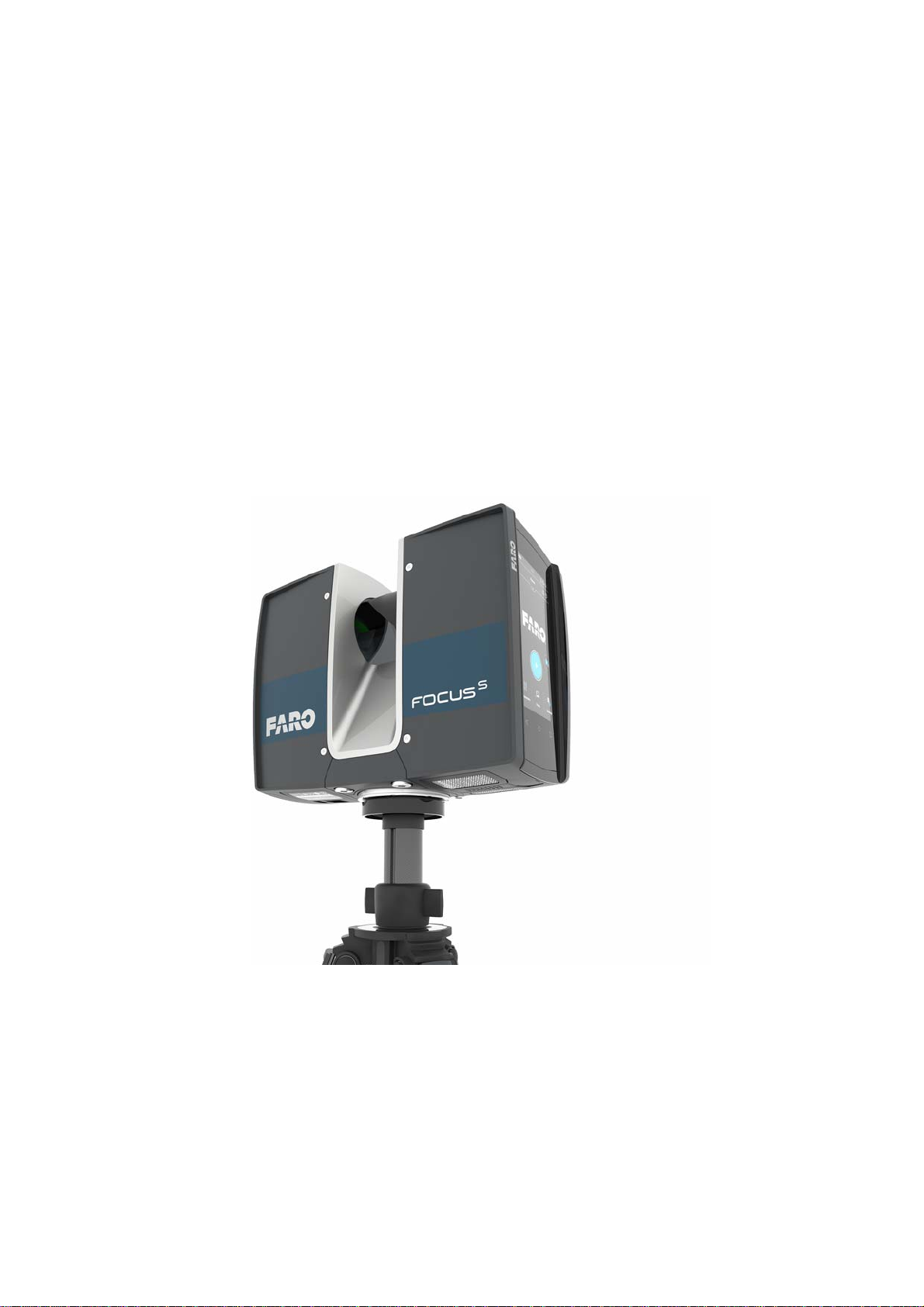
The FARO Laser Scanner is a high-speed three-dimensional laser scanner for
detailed measurement and documentation. The FARO Laser Scanner uses
laser technology to produce exceedingly detailed three-dimensional images of
complex environments and geometries in only a few minutes. The resulting
images are an assembly of millions of 3D measurement points.
Unless otherwise stated, we use the term FARO Laser Scanner for any of the
FARO Laser Scanner Focus
FARO®Laser Scanner Manual
M
70, FocusS 70, FocusS 150, or FocusS 350.
The Focus
M
70, FocusS 70, FocusS 150, and FocusS 350 are designed to scan
objects in a distance range between 0.6m and approximately 70, 150, and
350 meters.
S
The laser scanners of the Focus
M
Focus
series.
series offer a higher accuracy than the
Figure 2-1: FARO Laser Scanner
The main features are:
• HYPERMODULATION
TM
• high accuracy
• high resolution
• high speed
• intuitive control through the built in touchscreen display.
4
Chapter 2: Introduction
Page 10
FARO®Laser Scanner Manual
Mirror
Laser
• high mobility due to its small size, light weight, and the integrated quick
charge battery.
• High Dynamic Range (HDR) imaging method merges images captured with
different exposure settings to one image with a greater dynamic range of
luminosity.
• photorealistic 3D color scans due to the integrated color camera.
• integrated dual axis compensator to automatically level the captured scan
data,
• integrated GPS sensor to determine the scanner position.
• integrated compass and altimeter to give the scans an orientation and a
height information.
• WLAN to remotely control the scanner.
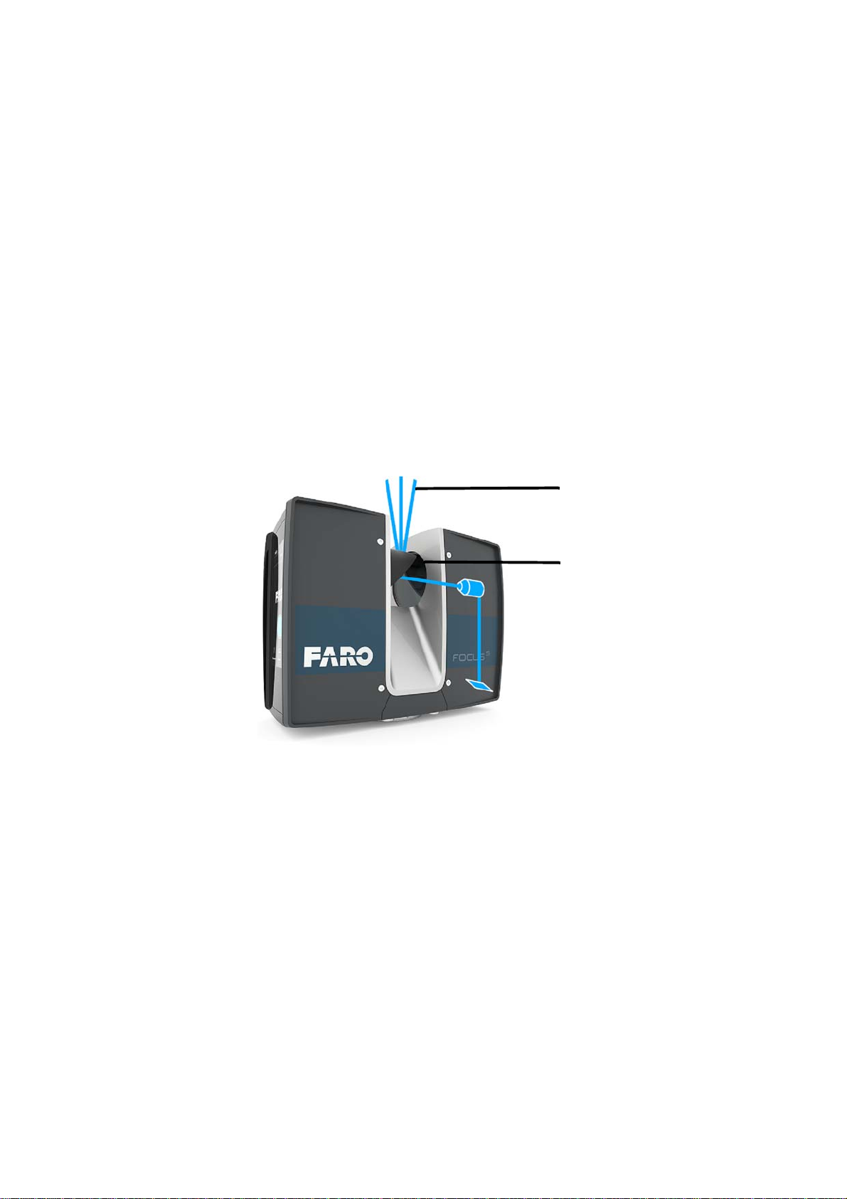
The FARO Laser Scanner works by sending an infrared laser beam into the
center of a rotating mirror. The mirror deflects the laser beam on a vertical
rotation around the environment being scanned; scattered light from
surrounding objects is then reflected back into the scanner.
Chapter 2: Introduction
Figure 2-2: Laser Deflection
To measure the distance, FARO Laser Scanner uses phase shift technology,
where constant waves of infrared light of varying length are projected outward
from the scanner. Upon contact with an object, the light is reflected back to the
scanner. The distance from the scanner to the object is accurately determined
by measuring the phase shifts in the waves of the infrared light.
HYPERMODULATION
modulated signal with the help of a special modulation technology. The x, y, z
TM
greatly enhances the signal-to-noise ratio of the
coordinates of each point are then calculated by using angle encoders to
measure the mirror rotation and the horizontal rotation of the FARO Laser
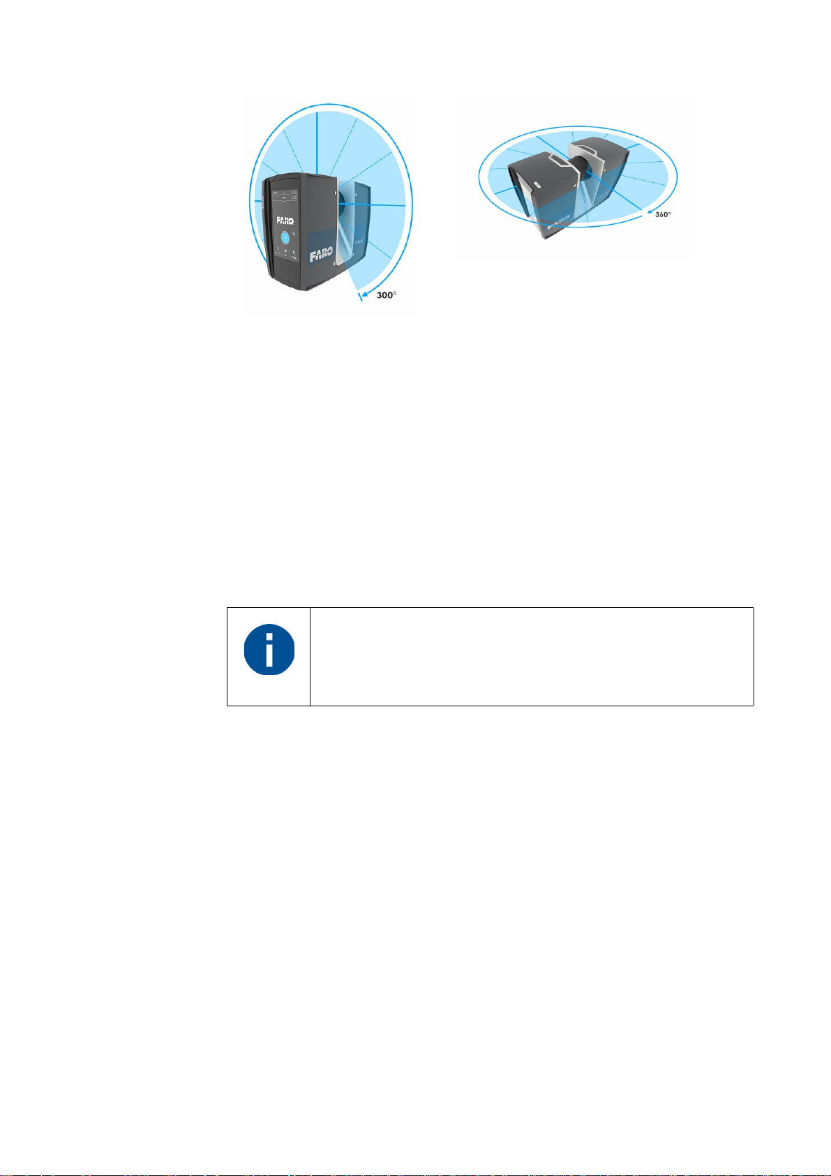
Scanner. These angles are encoded simultaneously with the distance
measurement. The scanner covers a 360° x 300° field of view.
Info einfügen, dass der senkrechte Sichtbereich nicht durchgängig 300°C
betragen kann.
5
Page 11
FARO®Laser Scanner Manual
Figure 2-3: Vertical and Horizontal Rotation
Additionally, the FARO Laser Scanner determines the reflectivity of the
captured surfaces by measuring the intensity of the received laser beam. In
general, bright surfaces reflect a greater portion of the emitted light than dark
surfaces. This reflectivity is used to assign a corresponding value to each
single point.
The single point measurements are repeated up to 976,000 times per second.
The result is a point cloud, a three-dimensional dataset of the scanner's
environment (hereinafter referred to as the laser scan or simply scan).
Depending on the selected resolution (points acquired per rotation) each point
cloud consists of millions of scan points.
The maximal single point measurement rate of the FocusM 70
is 488,000 times per second.
The laser scans are recorded on a removable SD card, enabling easy and
secure transfer to SCENE, FARO’s point cloud manipulation software.
This manual provides an introduction to the FARO Laser Scanner. Please
read the safety information in chapter
step-by-step guide in chapter
Getting Started on page 20 before first use.
Safety Precautions on page 10 and the
You can also find various training and tutorial videos on the Internet at http://
tutorial.faroeurope.com
The scanner also has an onscreen help that can be accessed during operation
by pressing the help button on the screen. For more information, see
Help and Notifications
on page 111.
Online
A list of the potential fields of application of the FARO Laser Scanner can be
found on the FARO web page www.faro.com.
6
Chapter 2: Introduction
Page 12

FARO®Laser Scanner Manual
7
Page 13
Chapter 3: Equipment
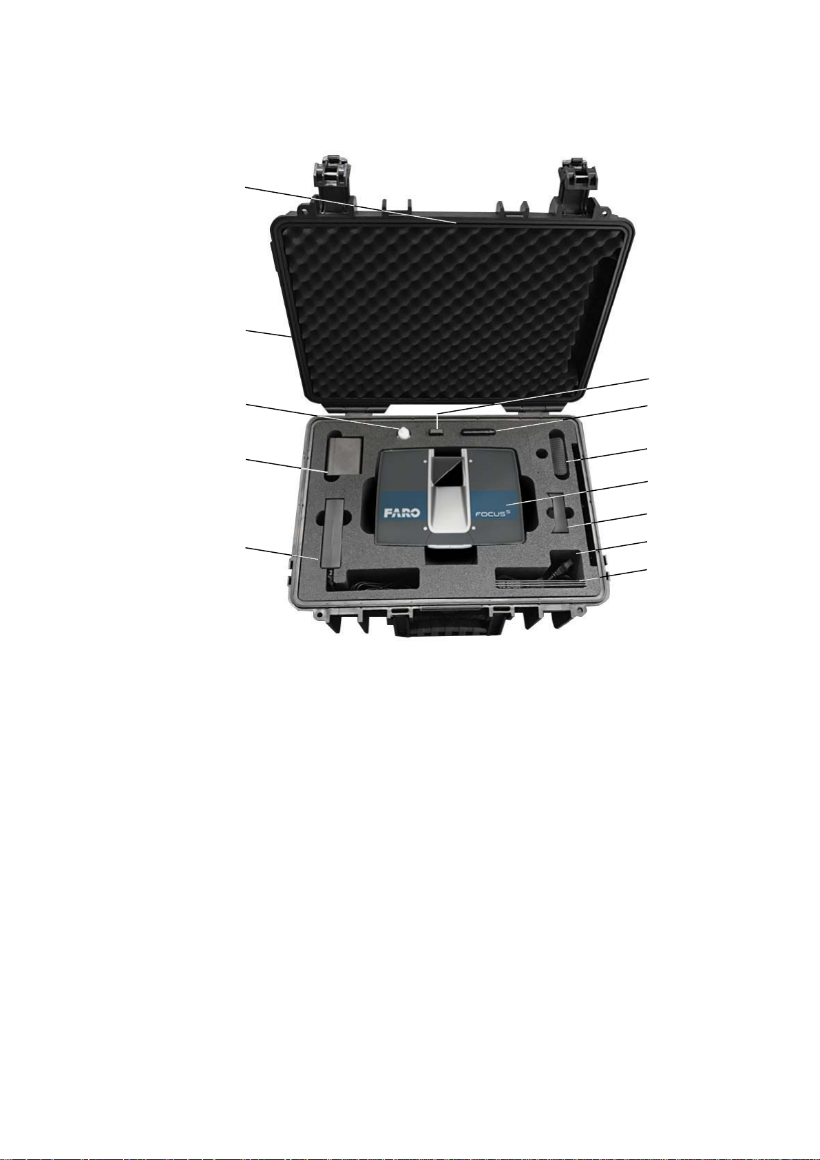
The FARO Laser Scanner is shipped with the following standard equipment:
FARO®Laser Scanner Manual
Scanner transport and carry case
Laser scanner. An SD card is already inserted in the scanner
Power supply unit
Power Block battery
FARO Quick Release
Mirror cleaning liquid for optics
SD card reader
Power Dock battery charging cradle
SD card cover
Quick Start Guide, situated in the case lid
USB stick with SCENE software and this user's manual (optional)
8
Chapter 3: Equipment
Page 14

FARO®Laser Scanner Manual
AC power cable
Recommended additional equipment:
• Tripod
• Spare battery
Retain all packing materials as you may need them later.
The SD memory card, a charged Power Block battery and a tripod are the
minimum required equipment you need to carry out a scanning project.
Chapter 3: Equipment
9
Page 15

Chapter 4: Safety Precautions
Please read this User's Manual carefully and completely and refer to it before
using the product. Pay close attention to all warnings and follow the
instructions step by step.
4.1 Intended Use
Please use the product with the operating conditions and limitations described
in this user manual.
4.2 Improper Use
Improper use means using the product other than described in this instruction
manual, or under operating conditions which differ from those described
herein.
Improper use of the product can impair the protection provided by the product,
and product damage or serious personal injury can be caused.
FARO®Laser Scanner Manual
4.3 Users
In the interests of safety, the laser scanner and its accessories should only be
used by competent, suitably trained users after they have read and
understood this manual, and considered any hazard involved.
We recommend that operators participate in the trainings offered by FARO.
4.4 General Safety Information
CAUTION:
• Do not open the housing. By opening the housing, serious personal injury
may be caused and you can damage the product, which will affect the
product's warranty.
• Do not use parts which have not been supplied or recommended by FARO.
• Only replacement parts authorized by FARO may be used according to the
instructions obtained from FARO.
• Do not expose the FARO Laser Scanner and its accessories to extreme
temperatures. The ambient temperature must not be lower or higher than
given in the specifications. Do not use the FARO Laser Scanner near heat
sources such as radiators, heat registers, or other products (including
amplifiers) that produce heat.
• Do not immerse the FARO Laser Scanner and its accessories into water.
Liquid in the product enclosure can lead to damage, fire, or electric shocks.
10
Chapter 4: Safety Precautions
Page 16
FARO®Laser Scanner Manual
• Properly dispose of the product and batteries in accordance to the national
regulations. For more information, see
Disposal on page 150.
• Do not use the FARO Laser Scanner and its accessories in an explosive
atmosphere. Do not operate the instrument in the presence of flammable
gases or fumes. Operation of any electrical instrument in such an
environment constitutes a definite safety hazard.
• Do not use the FARO Laser Scanner in vicinity of strong magnetic or
electrical fields.
• Before operating the FARO Laser Scanner and its accessories in
hazardous areas, please contact the local safety authorities and safety
experts.
•For outdoor use, please use the Power Block battery as the power supply
and ensure that the device is protected from rain or spray water. The
scanner should be used in a non-condensing environment.
• When the product is transferred from a cold to a significantly warmer
environment, water may condense on some elements inside the scanner.
To avoid this, we recommend placing the scanner in an airtight plastic bag
before bringing it from a cold to a significantly warmer environment. This
allows the condensation to form on the bag and not inside the scanner. If
you do not have the possibility to pack the scanner airtight, please wait until
observable condensation water evaporates from the scanner before
switching the FARO Laser Scanner
on.
• Properly dispose of the product and batteries in accordance to the national
4.5 Electrical Safety
WARNING: Do not open the housing. Dangerous high voltages are present
inside the enclosure. Only qualified service personnel should open the
housing. Never push objects of any kind into this product through openings as
they may touch dangerous voltage points or cause short circuits. This could
result in a fire, electric shock, and damage to the product.
• This product should be operated only from the power source or a battery
regulations.
DANGER
Do not operate the scanner while the external power supply
is plugged in. The power cable might damage the turning
scanner.
supplied or recommended by FARO. Please ensure that the specifications
of the AC converter are met by your line voltage. If you do not know the
power line voltage in your area, please consult your local power company.
Chapter 4: Safety Precautions
• To avoid electrical shock, use the power supply unit in dry indoor
environments only.
11
Page 17

4.5.1 Power Block Battery Safety Measures
Following safety measures must be followed when working with the Power
Block battery:
• Only use the charger recommended by FARO to charge the battery.
• Do not charge or discharge damaged batteries.
• Do not charge the battery in the FARO Laser Scanner when it is stored in
the transport case.
• Do not use wet or dirty batteries in the FARO Laser Scanner or with the
charger.
• Charge within limits of 0°C (32°F) and 45°C (113°F) temperature.
Recommended charging temperatures: 10°C (50°F) to 30°C (86°F).
• Discharge within limits of -20°C (-4°F) and 60°C (140°F) temperature.
Recommended operating temperatures: 5°C (41°F) to 40°C (104°F).
FARO®Laser Scanner Manual
• Insert or remove batteries from the laser scanner in dry and dust-free
environments only.
• When the FARO Laser Scanner is not in use for a longer period of time,
remove the battery.
• Store the battery only when it is charged (at least 60% charge state). It is
recommended to charge the battery once a year when it is stored longterm.
• Storage temperatures: -20°C (-4°F) to 45°C (113°F), storage humidity
range: 0% to 80%. Store in a well ventilated area. Do not store with metal
objects. A short circuit can cause a fire.
• Do not bring metal objects into contact with the batteries' terminals. The
terminals may short circuit and generate heat in this condition.
• Do not immerse batteries into water or fire (danger of explosion).
• Dispose of batteries in accordance with environmental regulations. Contact
your local waste disposal management authority for guidelines concerning
lithium ion batteries.
4.5.2 Power Dock Battery Charger Safety Measures
Observe the following safety measures when working with the FARO Power
Dock battery charger:
• Do not charge any batteries other than the FARO Power Block batteries in
the FARO Power Dock charger.
• Regularly check plug, cord and the charger itself. In case of damage
contact the FARO Customer Service.
12
Chapter 4: Safety Precautions
Page 18

FARO®Laser Scanner Manual
• Do not bring metal objects or fluids into contact with the charger terminals.
The terminals may short circuit and generate heat in this condition.
• To avoid electrical shock, use the charger and the power supply unit in dry
indoor environments only.
• Do not operate the charger in an environment allowing exposure to
moisture, combustible fluids or gases. Danger of explosion!
• The charger should be kept in a dry room, out of the reach of children.
4.6 Mechanical Safety
• WARNING: The mirror unit rotates with high speed while scanning and for
a short period after the scan. While the mirror is rotating keep distance to
the product and do not touch the rotating mirror unit with your hands,
fingers or any objects at the risk of personal injury and damage to the
FARO Laser Scanner.
• The FARO Laser Scanner will rotate clockwise up to 360 degrees when
performing a scan. Ensure that the scanner head of the FARO Laser
Scanner can rotate freely and will not hit any objects during the scan.
• CAUTION: The FARO Laser Scanner may only be used when set on a flat
and stable surface. Injuries may result if the FARO Laser Scanner
overturns. Only use equipment recommended by FARO and follow the
setup instructions in this manual or in the manual of the manufacturer of the
equipment.
If using a cart, move the setup with special care. Never move the cart by
pulling the power cables. Pushing or pulling of the cart with too much force,
sudden stops, or an uneven surface can cause an upset of the FARO Laser
Scanner.
CAUTION:
Do not open the housing. By opening the housing serious personal injury
can be caused and you can damage the product.
•Only replacement parts authorized by FARO can be used according to the
instructions obtained from FARO. Do not use parts which have not been
supplied or recommended by FARO.
4.7 Transport
Chapter 4: Safety Precautions
The following precautions must be taken when transporting the laser scanner
equipment:
• The laser scanner must be turned off during transportation or shipping in a
transport case.
• Remove the battery from the laser scanner before shipping.
13
Page 19

FARO®Laser Scanner Manual
• When carrying the laser scanner, take care not to drop it. Strong impact can
damage the laser scanner and render it incapable of proper operation.
• Carry the laser scanner separately from its equipment or, for best
protection, use the original transport case.
• When shipping and transporting the laser scanner by rail, sea, air, or in a
road vehicle, make sure to use its original transport case and a suitable
outer cardboard box for best protection against shock and vibration.
• The FARO batteries are lithium-ion batteries and are thus classified as
dangerous goods. When transporting or shipping the FARO batteries,
please ensure that you observe all applicable local and international rules
and regulations. For further information, please contact your local forwarder
before transportation or shipping.
• For lithium-ion batteries with less than 100 Wh energy content, an
exemption is provided that allows you to carry such a battery without further
paperwork. The maximum battery energy a single person can carry is 200
Wh.
NOTE: Please make sure that the total energy content of all batteries that you
(as a single person) carry is less than 200 Wh and that no single battery has
more than 100 Wh energy content.
4.8 Storage
4.9 Servicing
Prior to storing the laser scanner for a longer time:
• remove the battery.
• pack the scanner and the battery in its shipping case to protect it from
environmental hazards, dust, and dirt.
• Store all components in an environment where
• the humidity level is low,
• the temperature is relatively stable,
• they will not be subject to extreme temperatures, environmental
conditions, or heavy vibrations.
Servicing and repair must only be done by qualified service personnel
authorized by FARO. Unplug this product from the power outlet, remove the
battery and refer servicing to qualified service personnel under the following
conditions:
• The power-supply cord or plug is damaged.
• The product has been exposed to rain, water, or other liquids.
• The product has been dropped or damaged in any way.
14
Chapter 4: Safety Precautions
Page 20

FARO®Laser Scanner Manual
• Objects have fallen onto the product.
• The product does not operate normally by following the operating
instructions.
• The product exhibits a distinct change in performance.
• The required service and calibration date is reached.
Chapter 4: Safety Precautions
15
Page 21
Chapter 5: Parts and their Functions
5.1 Scanner Parts
5.1.1 Display Side
FARO®Laser Scanner Manual
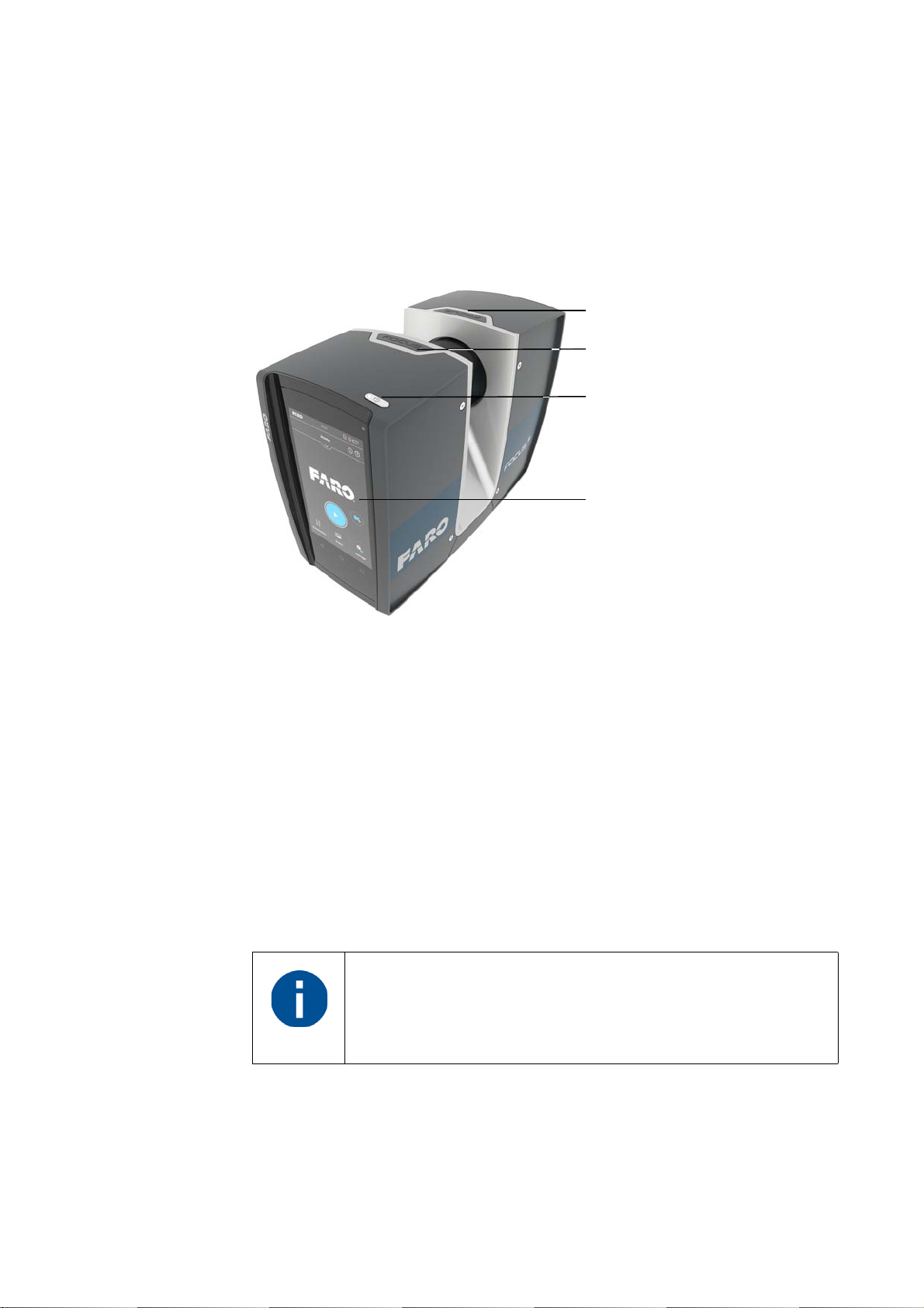
Figure 5-4: Display side of the FARO Laser Scanner
Power On/Off button - Press this button to power on the FARO Laser
Scanner. If the scanner is on and running, press this button to power it
down. Pressing and holding the button more than 3 seconds will switch the
FARO Laser Scanner off without shutting down. Use this option only in
exceptional cases, for example, if the shutdown mechanism does not work
or the FARO Laser Scanner is non-responsive.
Touch-screen display
Electrical Interface 1
Electrical Interface 2
The Electrical Interfaces 1 and 2 are not available in FocusM
70. For details on the Electrical Interfaces of FARO Laser
Scanner Focus
related Automation Interface Manual.
S
70, FocusS 150 and FocusS 350 check the
16
Chapter 5: Parts and their Functions
Page 22
FARO®Laser Scanner Manual
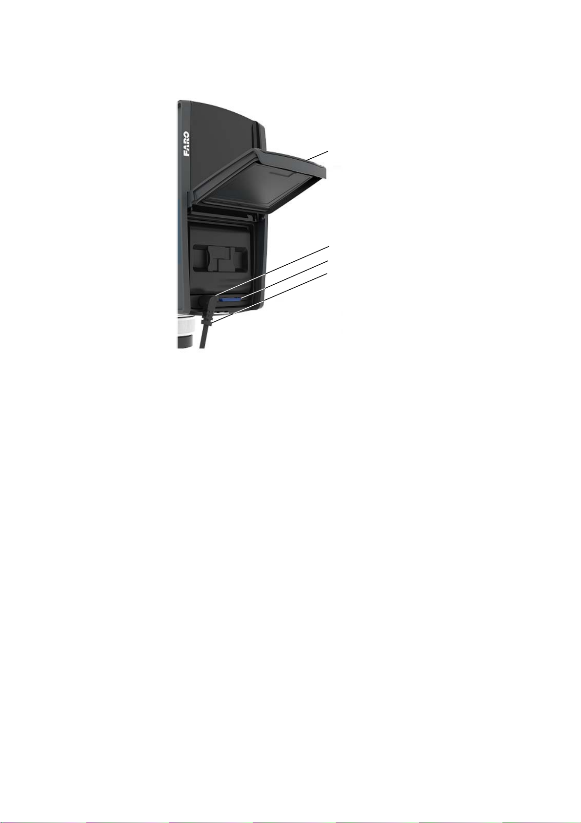
5.1.2 Battery Side
Figure 5-5: Battery Side of the FARO Laser Scanner
Battery compartment cover
Socket to plug an external power supply
LED showing battery status
SD card slot
Chapter 5: Parts and their Functions
17
Page 23
5.1.3 Front Side
FARO®Laser Scanner Manual
5.1.4 Bottom Side
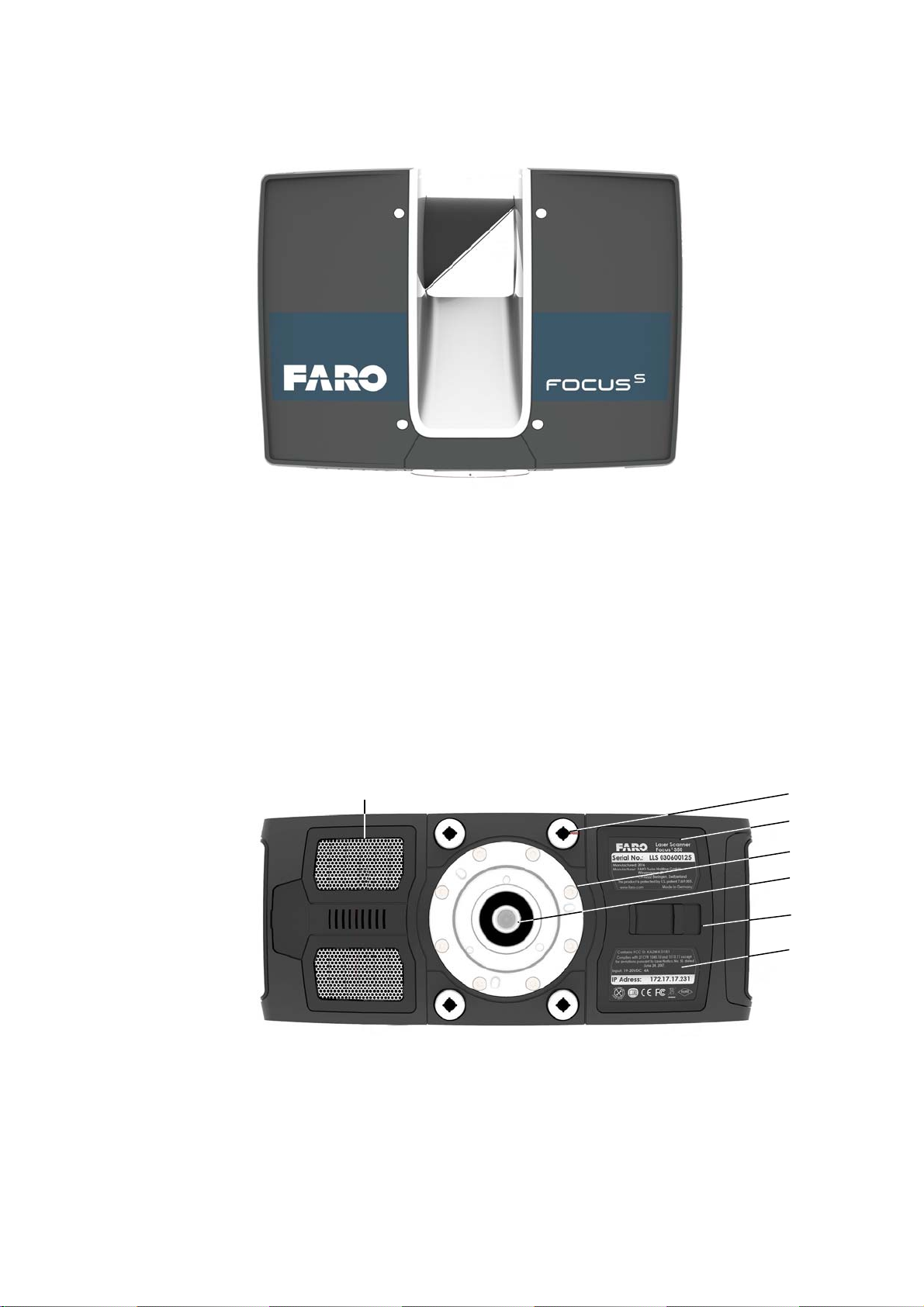
Figure 5-6: Front View of the FARO Laser Scanner
Scanner mirror - for safety and cleaning instructions see Mechanical
Safety
Scanner mount
Reference area - used for self-referencing the distance measurements
while scanning
on page 13 and Cleaning Instructions for Optics on page 129.
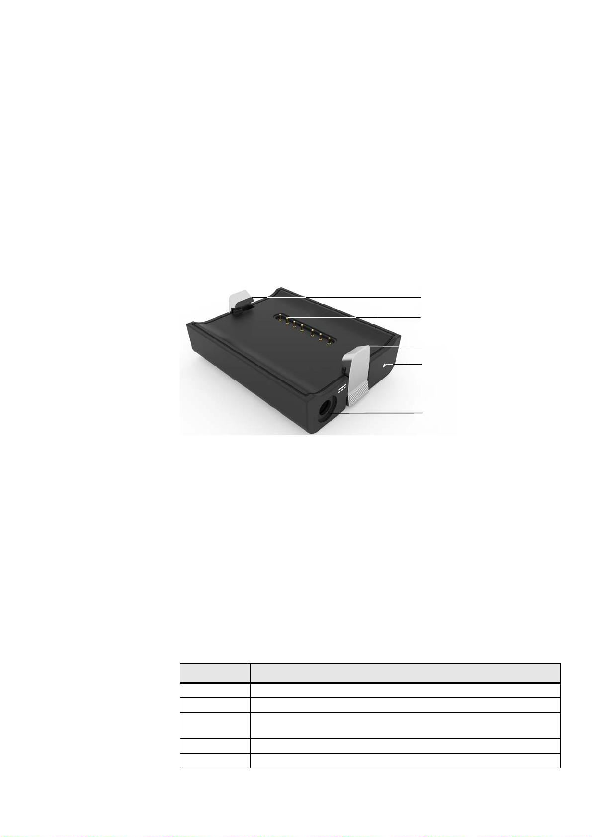
Figure 5-7: Bottom View of the FARO Laser Scanner
3/8” screw thread to mount the scanner to standard photo tripods.
M5 screw threads to mount the scanner to customer specific fixtures.
18
Chapter 5: Parts and their Functions
Page 24
FARO®Laser Scanner Manual
Cover of the automation interface for automated applications. Remove to
get access to the automation interface of the FARO Laser Scanner. For
more information, please read the FARO Laser Scanner automation
interface manual. Cover the automation interface if it is not needed or not
in use.
Type label.
Cooling fan openings - please keep these openings uncovered to ensure
proper cooling of the scanner.
) Battery compartment cover release mechanism.
5.2 Power Dock Battery Charger
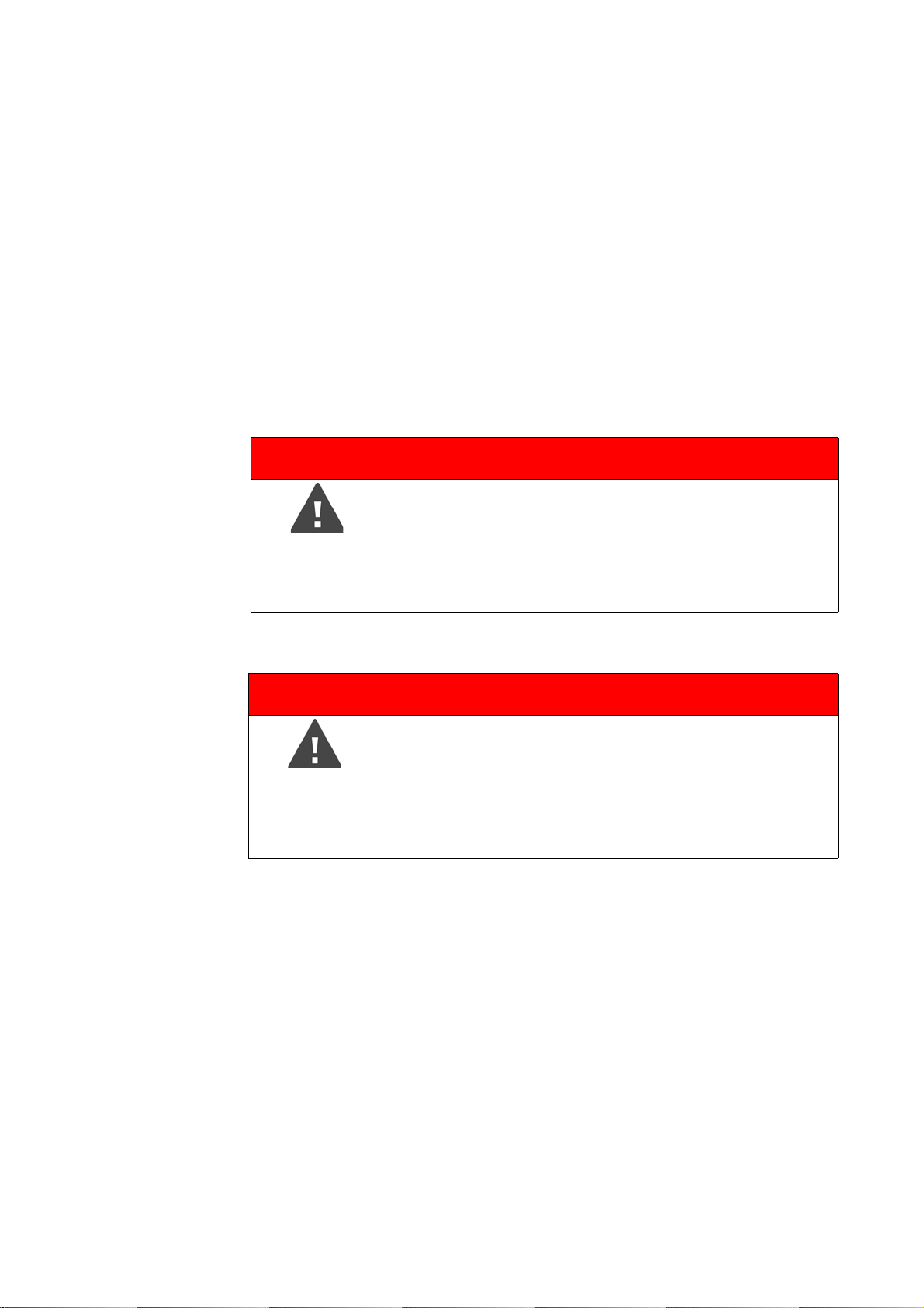
Figure 5-8: Power Dock Battery Charger
Safety clamps. To insert the battery, drag downwards.
Connectors
Power socket
Power LED - for LED specifications please see the table below.
5.2.1 LED behavior when charging cradle connected to power source
When the charging cradle is connected to the scanner or power source, its
LED displays the same status as the scanner LED.
Color State
Cyan Battery charging, state of charge is above 90% (charge done)
Orange Battery charging
Orange
flashlight
Red Unknown power source. Battery and AC adapter are not detected
Red flashlight Battery deep discharge
Battery charging, state of charge less than 10%
Chapter 5: Parts and their Functions
19
Page 25
Chapter 6: Getting Started
This chapter will provide preliminary steps and basic FARO Laser Scanner
operations and will guide you step-by-step from setting up the FARO Laser
Scanner to recording your first scan.
6.1 Charging the Battery
The Power Block battery can be charged in the FARO Laser Scanner or in the
FARO Power Dock battery charger. Carefully read the safety measures
described in
Charger Safety Measures
It is recommended to fully charge the battery before use. Please retain a spare
battery, if required, during your scan project.
DANGER
FARO®Laser Scanner Manual
Power Block Battery Safety Measures and Power Dock Battery
before using them.
Danger of explosion or fire
• Do not immerse batteries into water or fire.
• Do not bring metal objects into contact with the battery
terminals. The terminals may short circuit and generate
heat in this condition.
DANGER
Danger of fire or electric shocks
Ensure that the devices are protected from rain or spraying
water.
• The power supply unit and the Power Dock battery
charger are not for outdoor use.
The power supply unit can be used in many countries. It is compatible with a
100 V AC to 240 V AC 50/60 Hz power source. Use a plug adapter when
necessary.
6.1.1 Charging the Battery in the FARO Laser Scanner
1. Open the scanner's battery compartment cover.
2. Turn the battery so that its type label is directed upwards, point the battery
contacts to the scanner, push the battery straight in, and slide it downward
into the battery compartment until the fastener clicks into position.
20
Chapter 6: Getting Started
Page 26
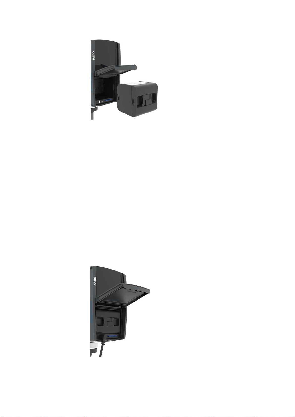
FARO®Laser Scanner Manual
Figure 6-9: FARO Laser Scanner with Battery
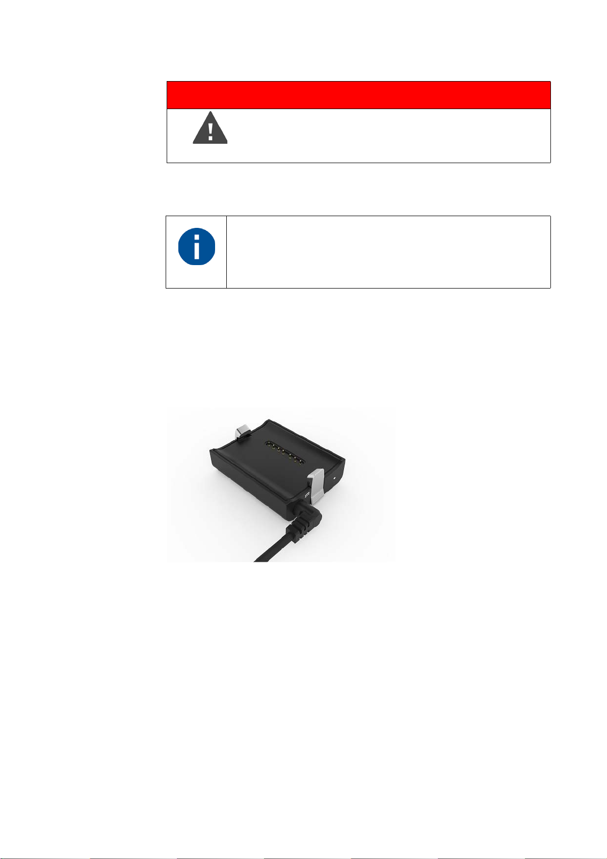
3. Connect the cable of the power supply unit to the power socket of the
FARO Laser Scanner. If you forcibly insert the plug in a wrong direction, the
plug and the FARO Laser Scanner can be damaged.
4. Connect the AC power cable to the power supply unit as well as to a power
outlet. Check the input voltage on the type label before connecting.
5. If the FARO Laser Scanner is turned off, the LEDs of the scanner will start
blinking blue while charging. The LEDs will stop blinking and will illuminate
to constant blue when the battery is fully charged.
6. If the FARO Laser Scanner is turned on, you can check the charging state
of the battery in the scanner's user interface under
General Settings > Power Management. For more information, see Power
Management
on page 90.
Home > Manage >
7. When charging is finished, remove the cable of the power supply unit and
close the battery compartment cover.
Chapter 6: Getting Started
Figure 6-10: Power Supply connected to FARO Laser Scanner
21
Page 27
FARO®Laser Scanner Manual
DANGER
Do not operate the scanner while the external power
supply is plugged in, as the power cable might damage the
turning scanner.
The FARO Laser Scanner need not be switched on to charge the battery.
Remove FARO Laser Scanner from the transport case before
connecting the power supply to the scanner.
Before prolonged storage, remove the power supply unit and
the battery from FARO Laser Scanner.
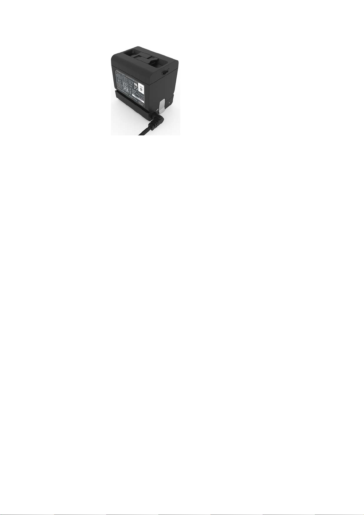
6.1.2 Charging the Battery with the Power Dock Battery Charger
1. Connect the cable of the power supply unit to the power socket of the
FARO Power Dock battery charger. If you forcibly insert the plug in a wrong
direction, the plug and the Power Dock battery charger can be damaged.
Figure 6-11: Power Dock battery charger with connected power cable
2. Connect the AC power cable to the power supply unit as well as to a power
outlet. Check the input voltage on the type label before connecting.
3. The LED of the Power Dock battery charger illuminates blue when power is
connected correctly.
4. Place the battery on top of the Power Dock battery charger. Ensure that the
battery terminals are aligned correctly with the pins of the charger. Let the
battery snap into place.
22
Chapter 6: Getting Started
Page 28
FARO®Laser Scanner Manual
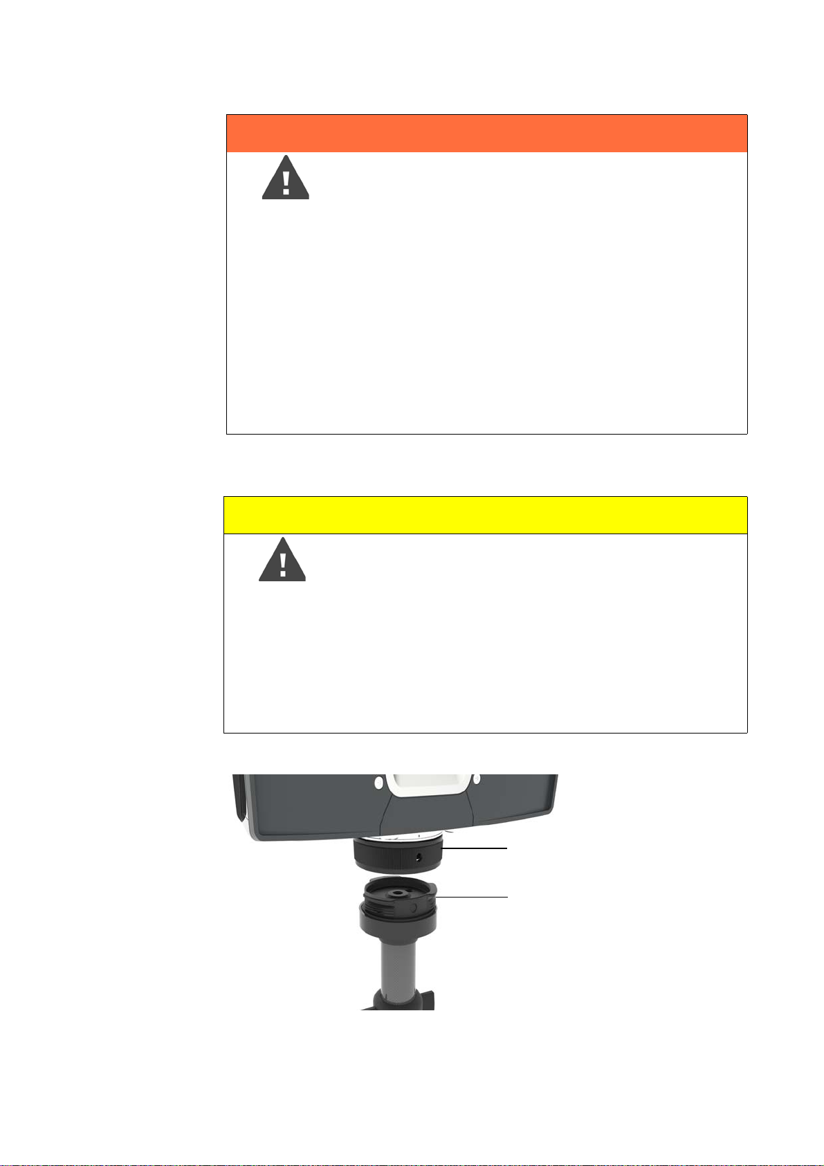
Figure 6-12: Placing the battery on the Power Dock battery charger
5. Charging starts automatically; the LED blinks and illuminate according to
the current charging state of the battery. For more information, see
Dock Battery Charger
on page 19.
Power
6. After charging, carefully press the charger interlock mechanism and
remove the battery out of position.
6.1.3 Tips for Using the Battery
• Charge the battery the day it is to be used or on the day before. A charged
battery that is unused, will gradually lose power over time.
• If the battery becomes exhausted quickly after being fully charged, replace
it with a new one.
• For best battery performance, an ambient temperature of 0°C (32°F) to
40°C (104°F) is recommended. In colder or warmer locations, battery
performance and operation time may temporarily decrease.
Chapter 6: Getting Started
23
Page 29
6.2 Setting up the FARO Laser Scanner
1
2
WARNING
Danger of injuries, especially to children or kneeling
persons
Injuries may result if the FARO Laser Scanner overturns.
• The FARO Laser Scanner may only be used when set
on a flat and stable surface.
• If using a cart, move the setup with special care. Never
move the cart by pulling at the power cables. Pushing or
pulling of the cart with too much force, sudden stops, or
an uneven surface can cause an upset of the
FARO Laser Scanner.
• In windy conditions, use a heavy weight or sandbags
attached to the center hook of the tripod to stabilize and
secure the tripod.
FARO®Laser Scanner Manual
Although the scanner can be mounted directly onto a tripod, using the FARO
Quick Release is recommended for ease of use.
Caution
Danger of Injury
Do not use the FARO Quick Release when mounting the
scanner in an inverted position. The scanner could fall and
be damaged or cause injury to bystanders.
If you need to mount the scanner in an inverted position
(i.e., upside down), use the 3/8” or M5 screw threads and
ensure that the screws are equipped with a locking
mechanism to prevent unintentional loosening.
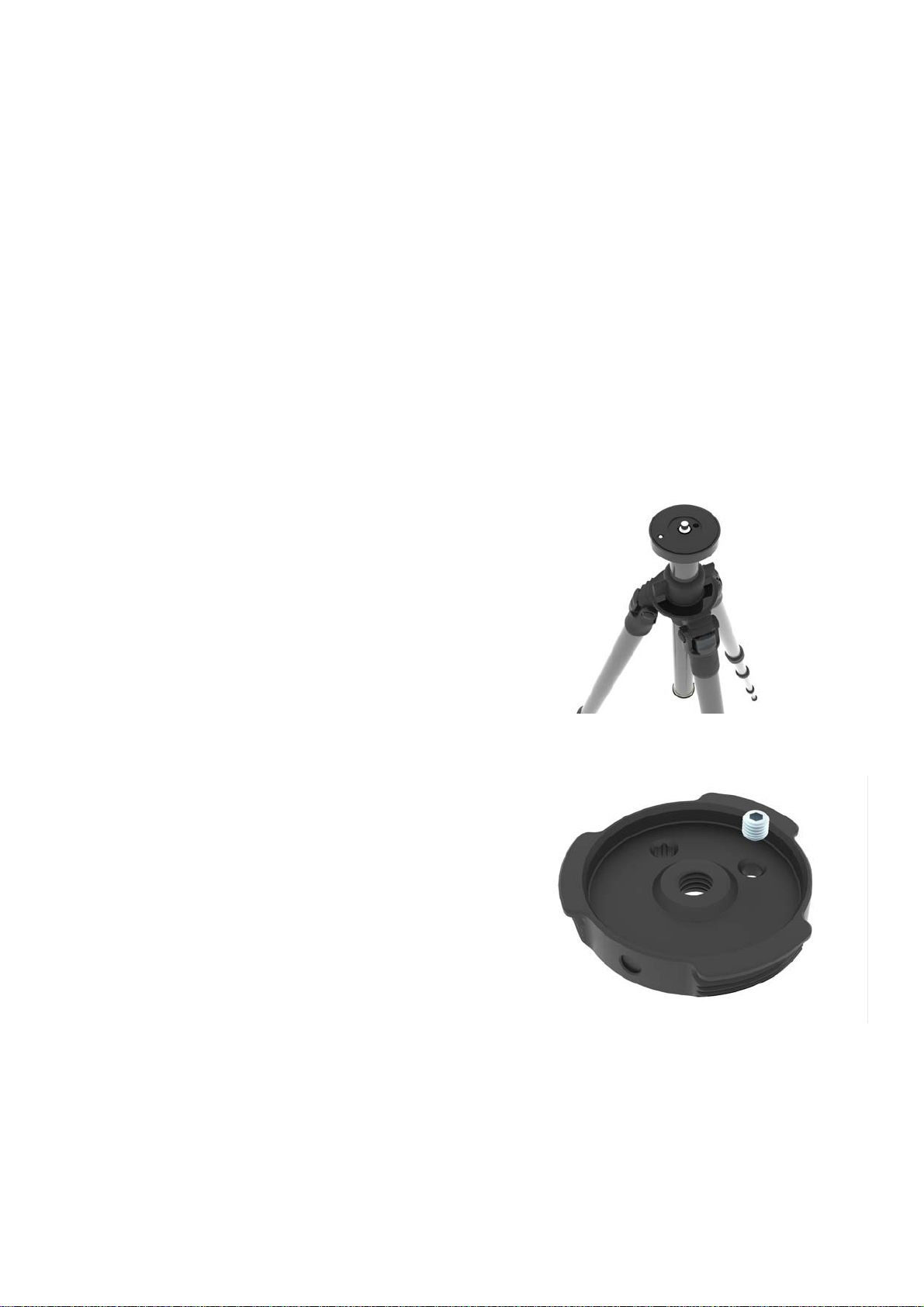
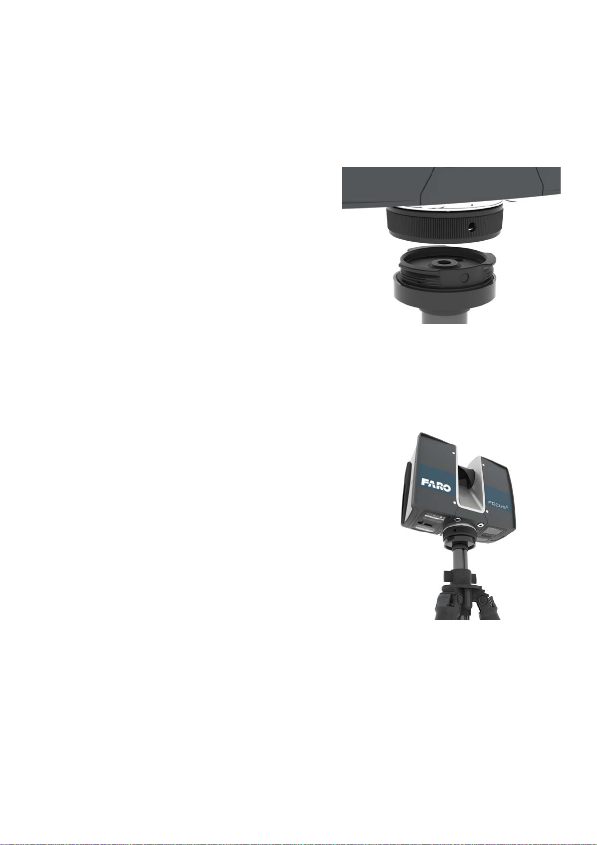
The Quick Release consists of two main parts: the base plate (1) to be put on top of
the tripod’s platform, and the mount plate (2) to be attached underneath the scanner.
The Quick Release is packaged with two hex keys which are needed for mounting:
24
Chapter 6: Getting Started
Page 30
FARO®Laser Scanner Manual
• An imperial 3/16” hex key for the central 3/8” thread in the mount plate and
for tightening the base plate
• A metric S3 hex key for the set screw in the base plate, also used as an
interlock when tightening the mount plate
When preparing the tripod for the first time, you might also need the hex key
that was delivered with the tripod to recess the tripod’s set screw.
The procedure contains the following steps.
1. Set up the tripod
2. Attach the base plate to the tripod
3. Attach mount plate underneath the scanner
4. Mount the scanner
1. Set up the tripod • Extend the legs of the tripod
and lock the leg angle clips.
2. Attach the base
plate to the tripod
• Ensure that the tripod is
stable, the feet are secured,
and the platform is as level
as possible.
• Your tripod might be
equipped with one or more
set screws in the platform.
Ensure that the set screws
are recessed below the
platform. They must not
stick out of the surface.
The base plate of the Quick
Release has a central 3/8”
thread for mounting it on the
tripod, and a set screw for
secure tightening. The base
plate also provides a hexagonal
recess which is used when
tightening it to the tripod’s
platform, or removing it.
Chapter 6: Getting Started
25
Page 31
FARO®Laser Scanner Manual
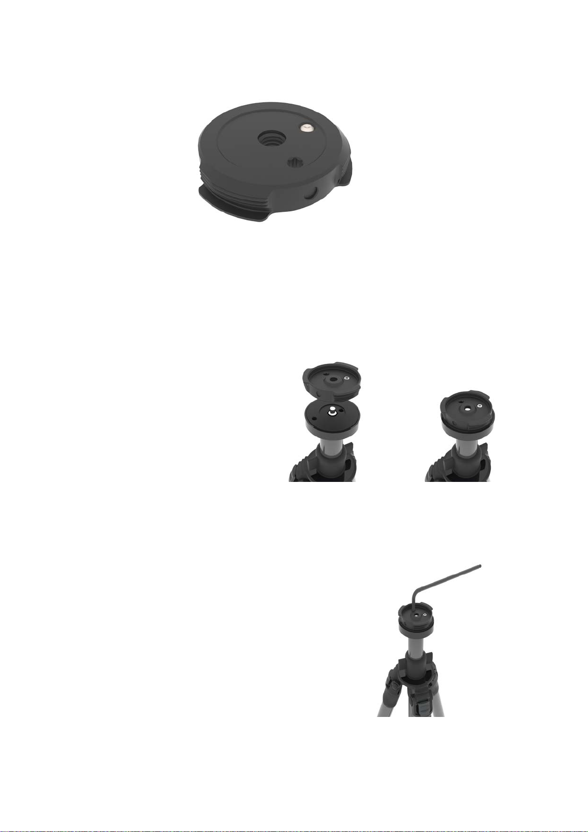
1.Ensure that the set screw
is recessed. It must not stick
out of the surface facing the
platform of the tripod. If it
sticks out of the surface, use
the S3 hex key to recess it.
2. Mount the
base plate on
the tripod,
using the
central 3/8”
threaded stud
of the tripod.
Tighten it
manually.
3. Put the 3/16” hex key into
the hexagonal recess on the
base plate and use it as a
lever to tighten the base
plate firmly.
26
Chapter 6: Getting Started
Page 32
FARO®Laser Scanner Manual
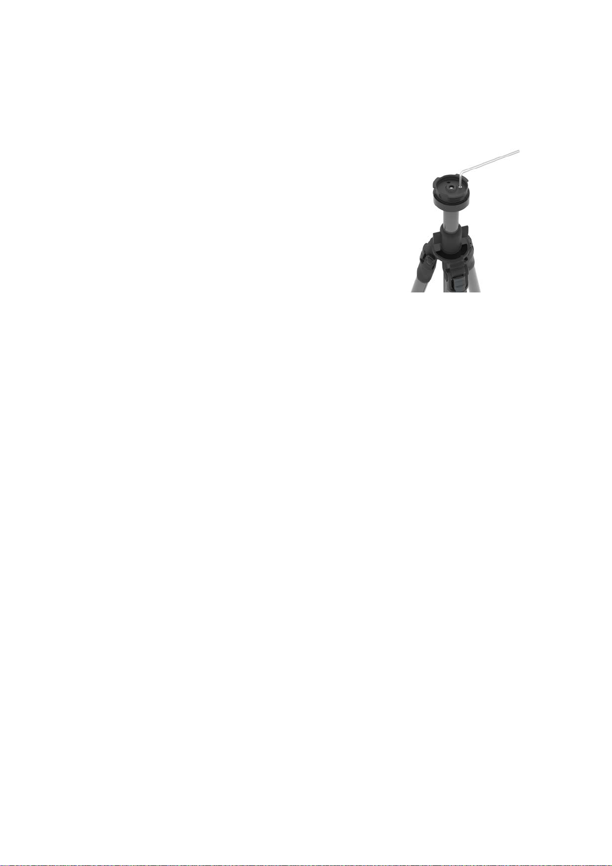
4. Use the S3 hex key to
tighten the set screw of the
base plate completely
against the platform of the
tripod.
The base plate is now securely tightened on the tripod’s platform, and unable
to spin in any direction.
Chapter 6: Getting Started
27
Page 33
FARO®Laser Scanner Manual
3. Attach mount plate
underneath the
scanner
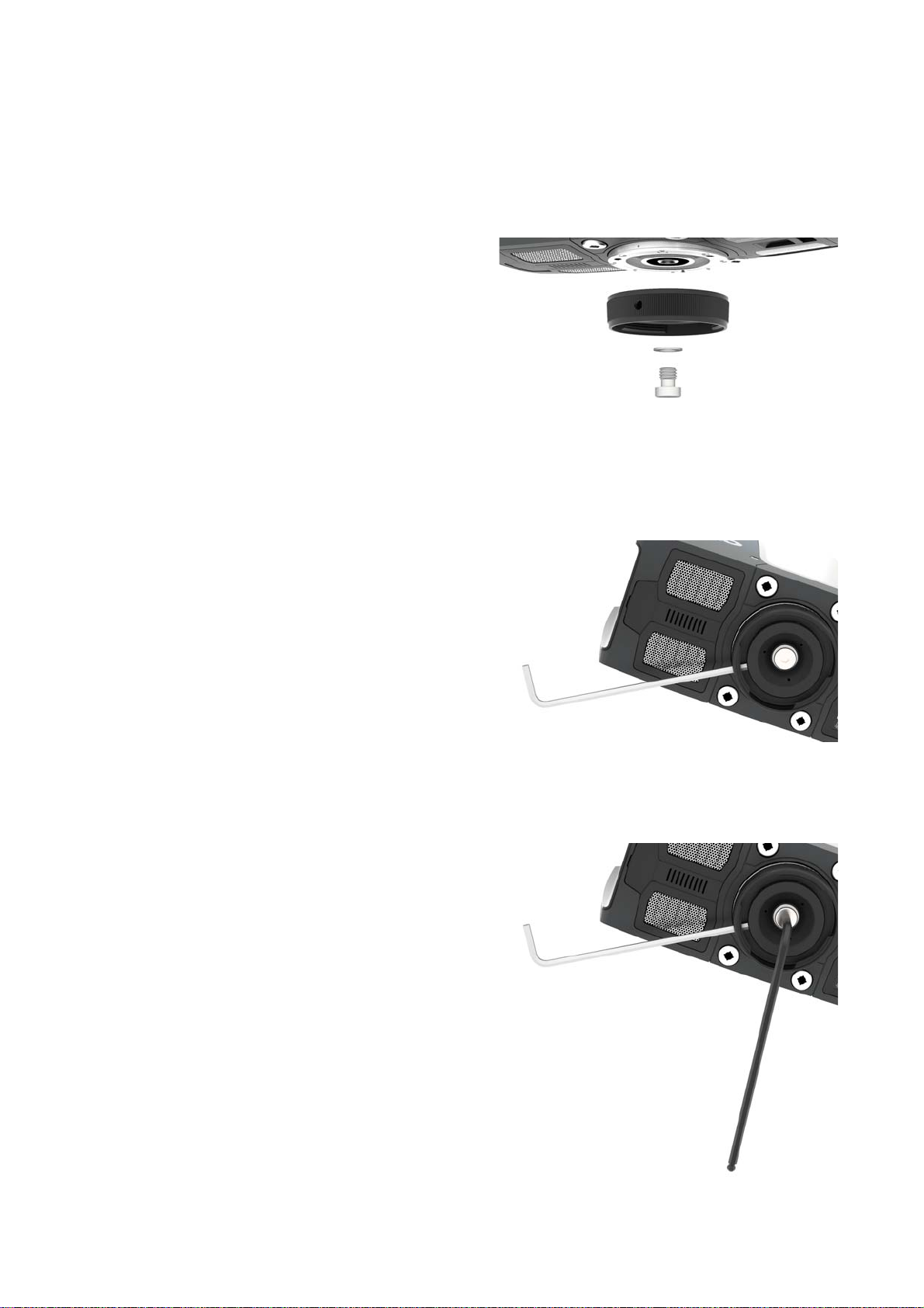
The mount plate of the Quick Release has a central 3/8” screw for mounting it
underneath the scanner. The threaded collar has three openings which are
used in combination with the six openings of the inner ring to interlock the
mount plate while tightening it.
1. Attach the mount plate to the
scanner, using the central
3/8” screw. Do not tighten
firmly in this first step.
2. Put the S3 hex key (shown
here in silver) as an interlock
into one of the three
openings of the threaded
collar. Slightly turn the collar
and find a spot where the
hex key fits into one of the
six openings of the inner
ring. Make sure that the hex
key actually went into one of
the six openings of the inner
ring.
3. Tighten the central 3/8”
screw with the
corresponding hex key,
while holding the interlock
steady. Do not use the
interlock as a lever.
28
Chapter 6: Getting Started
Page 34
FARO®Laser Scanner Manual
The mount plate is now securely attached to the scanner.
4. Mount the
scanner
1. Align one of the three holes
of the threaded collar with
the corresponding mark of
the base plate.
2. Put the scanner on the base
plate.
3. Turn the scanner to change
its orientation so that it fits
your individual needs for the
scan. Then tighten the
threaded collar firmly. Test if
the scanner is correctly
locked in place by gently
attempting to lift it from the
tripod.
Chapter 6: Getting Started
The scanner is now physically set up for scanning. Before you begin to scan,
check the outer casing for any signs of damage or distortion. Check mirror for
damage due to scratches, cracks, distortion and inspect for cleanliness.
29
Page 35
6.3 SD Card
6.3.1 Preparing an SD Card
The FARO Laser Scanner stores the recorded scans on a removable SD card.
This memory card can also be used to create backups of the scanner settings,
to import scanner settings, and to install firmware updates.
Before carrying out a scan project, you can use the SCENE software to set up
an SD card with project relevant information and settings, like the project
structure, scan profiles, or scanner operators. These settings can then be
transferred to the scanner. For more information on scan project preparation
with SCENE and transferring data to the scanner, please see the SCENE user
manual and
You can use SD, SDHC or SDXC cards. Memory cards with a size up to
64 GB have been verified to operate with the scanner. We recommend using
memory cards with a capacity of 4 GB or more. The speed of the card must be
Class 6 or better and its temperature range should be from -20 °C (-4 °F) to
85 °C (185 °F).
FARO®Laser Scanner Manual
SD Card on page 103.
The SD cards must be formatted in the FAT32 file system.
When using an SD card other than the supplied one, please
format it with the scanner format function first. For more
information, see
SD Card on page 30.
SD and SDHC cards may also be formatted with Windows. SDXC cards with a
capacity of more than 32 GB cannot be formatted with the Windows format
function as Windows will format those cards in its own file system. The
Windows file system is not supported by the scanner. There exist freeware
tools that allow formatting such cards with Windows as FAT32 but it is
recommended to use the scanner‘s format function.
NOTICE
Risk of data loss
• Do not remove the SD card from the scanner while it is
busy, otherwise you risk corrupting the data on the card.
A busy SD card is indicated by the SD card icon blinking
in the status bar of the controller software.
It is safe to remove the card from the scanner when this
icon has disappeared from the status bar.
• When removing a FARO Laser Scanner SD card from
your computer, you should always use the “Safely
Remove Hardware” option from the system tray in
Windows, otherwise you risk corrupting the data on the
SD card. To safely remove hardware in Windows,
double-click on the Safely Remove Hardware button in
the system tray, then select the device you want to
remove from the list.
30
Chapter 6: Getting Started
Page 36
FARO®Laser Scanner Manual
6.3.2 File Structure of the SD Memory Card
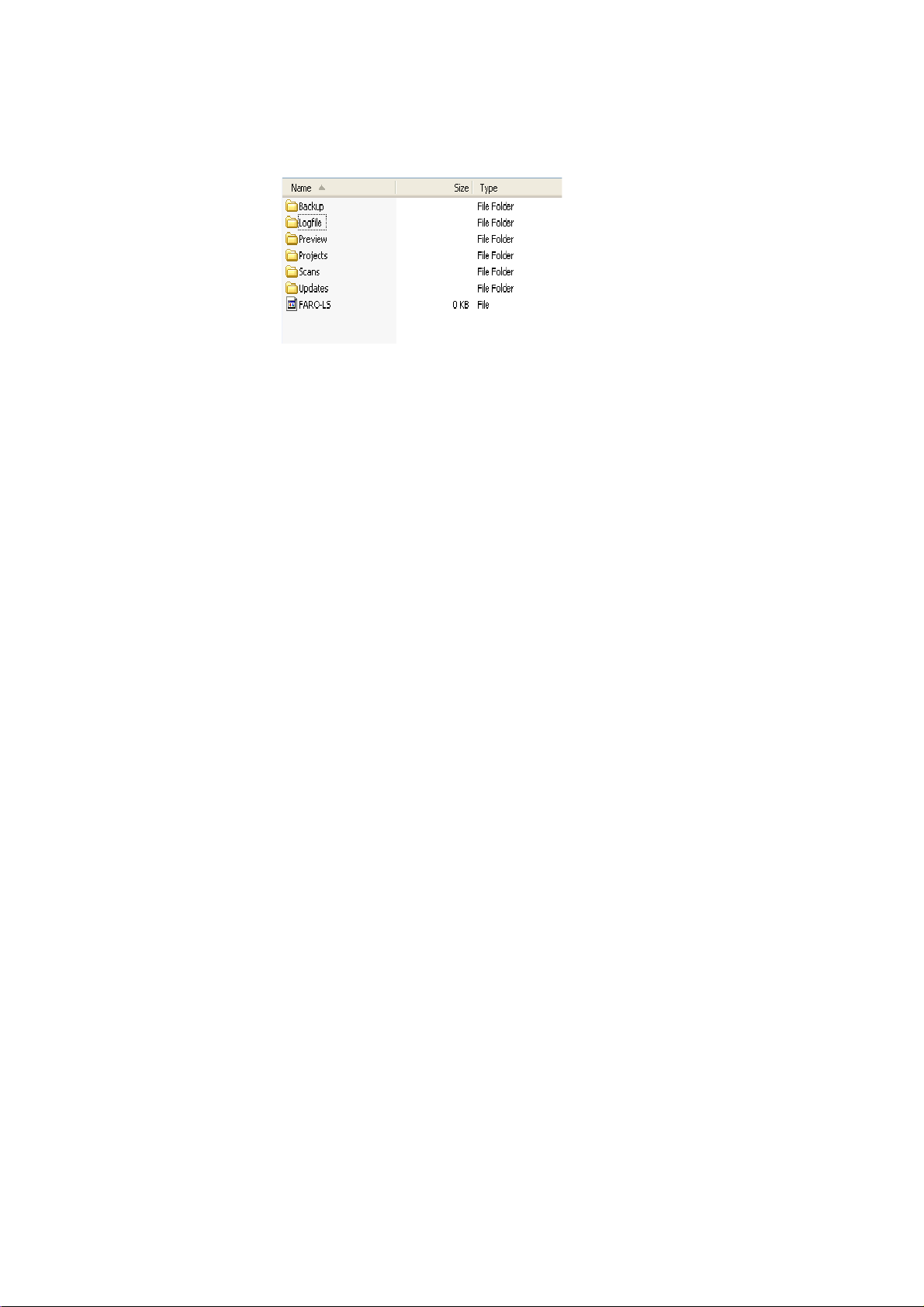
The file structure of the FARO Laser Scanner SD cards is as follows:
Figure 6-13: SD Card File Structure
Backup - Scanner backups will be saved to this folder. The backup folder will
be created automatically as soon as you start a scanner backup. See
on page 104.
Logfile - When exporting the log files from the scanner, they will be saved to
this folder. This folder will be created automatically by the scanner. See
File
on page 104.
Backup
Log
Preview - The preview pictures of captured scans will be saved to this folder.
The folder will be created automatically as soon as you start a scan. See
Starting a Scan on page 48.
Projects - Scan projects information will be saved to this folder. The folder will
be created automatically by the scanner. See
Scan Projects and Clusters on
page 68.
Scans - The captured scans will be saved to this folder. The scans folder will
be created automatically as soon as a scan has been started. See
Scan
on page 48.
Starting a
Updates - Copy firmware updates to this folder. This folder must be created
manually. See
Firmware Update on page 107.
FARO-LS - Signature file, used to identify the SD card as a FARO Laser
Scanner card. This file will be created automatically as soon as a scan has
been started.
Chapter 6: Getting Started
31
Page 37
6.3.3 Inserting the SD Card
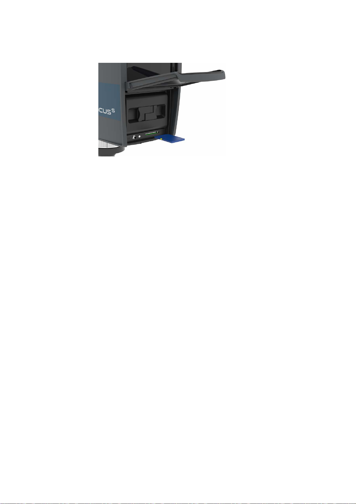
Figure 6-14: Inserting the SD Card
1. Open the battery compartment cover to find the SD card slot down on the
right side.
FARO®Laser Scanner Manual
2. Insert the formatted SD card with the notched edge in the direction as
illustrated until it clicks.
3. Confirm the direction of the memory card. If you forcibly insert the memory
card in a wrong direction, the SD card, the card slot or data on the card can
be damaged.
4. Close the cover.
Ejecting the SD Card
To remove a SD card from the scanner, open the SD card slot cover and lightly
push the memory card.
• Do not eject the memory card while it is busy.
• Take care that the memory card does not pop out and fall.
6.4 Switching the FARO Laser Scanner On
Pressing the scanner's On/Off button will start the boot process, which is
indicated by the scanner LEDs blinking blue. If power is supplied by the
battery and its charge state is too low to start the scanner, the scanner LEDs
will blink orange.
When the FARO Laser Scanner is ready, the LEDs will stop flashing and will
illuminate constantly blue, the Home screen of the scanner's controller
software will appear on the integrated touch screen.
32
Chapter 6: Getting Started
Page 38
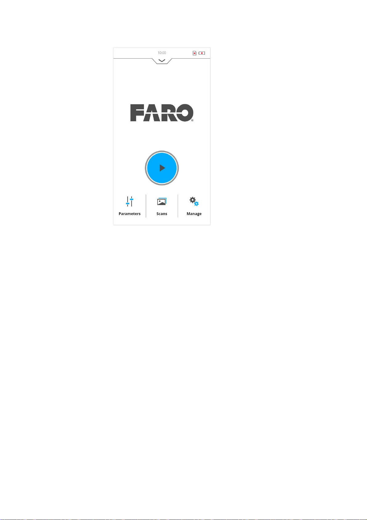
FARO®Laser Scanner Manual
Figure 6-15: Home Screen of the controller software
The FARO Laser Scanner can be operated to its full extent by simply tapping
the elements on the screen with your fingers. You can use a capacitive stylus
to navigate through the user interface.
6.5 Initial Scanner Settings
This chapter gives you a brief description on how to set up initial scanner
settings using the scanner's controller software on the integrated touch
screen. See
6.5.1 Setting the Interface Language
Starting from the Home screen, go to Home > Manage > General Settings >
Language to change the language of the controller software.
Controller Software for more information.
Chapter 6: Getting Started
33
Page 39
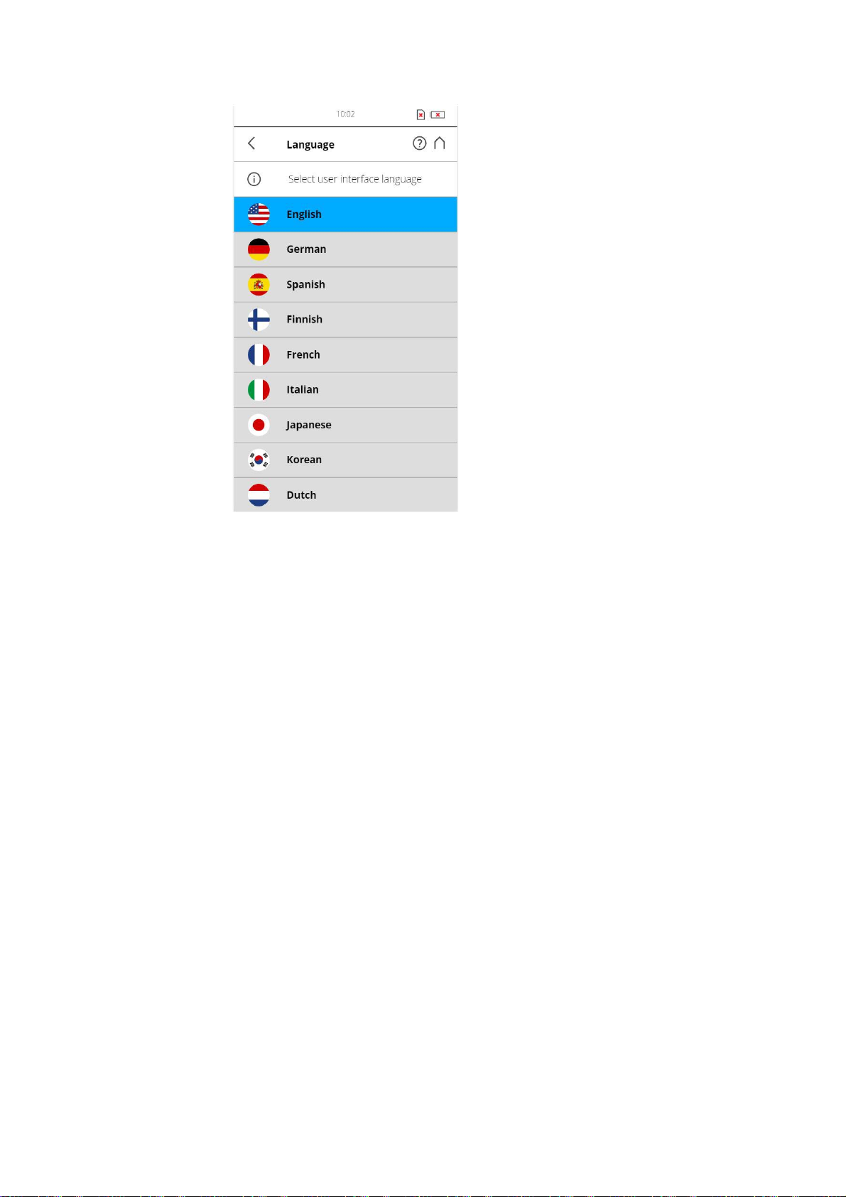
FARO®Laser Scanner Manual
Figure 6-16: Language Selection Screen
Select the language by tapping the corresponding button. The selected
language will be highlighted.
If the list of available languages exceeds the screen size, scroll the list up or
down.
34
Chapter 6: Getting Started
Page 40
FARO®Laser Scanner Manual
6.5.2 Setting the Date and Time
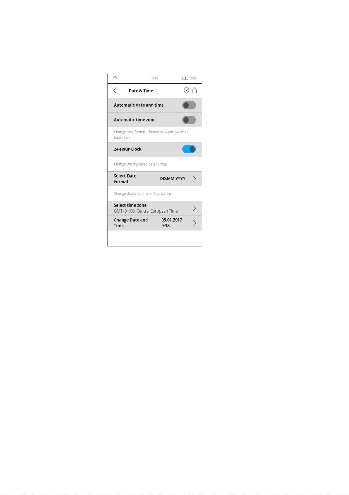
To change the date and time settings, go to Home > Manage > General Sett in gs >
Date & Time.
Figure 6-17: Date and Time Settings
Automatic date and time - Tap and slide the button to activate automatic date
and time settings.
Automatic time zone - Tap and slide the button to activate automatic time zone
settings.
24-Hour Clock - Tap to set the time format. The scanner can display time
either in the 24-hour or the 12-hour clock format. Slide the button to ON to
select the 24-hour clock. Slide the button to OFF to select the 12-hour clock.
Select Date Format - Tap to choose the date format. The currently selected
date format is displayed with the option.
Select time zone - Tap to choose the date format. The currently selected date
format is displayed with the option.
Change date and time - Tap to set the internal clock of the FARO Laser
Scanner.
Chapter 6: Getting Started
35
Page 41
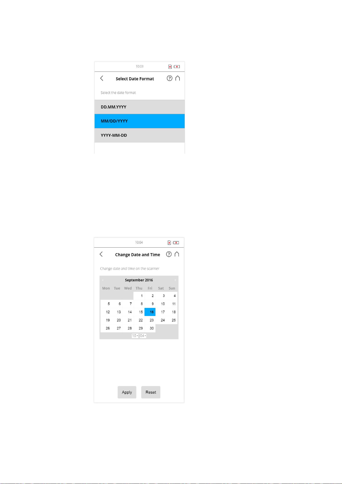
6.5.3 Setting the Date Format
Figure 6-18: Change Date Format
Select the date format by touching the corresponding button. You can select
between the date formats DD.MM.YYY, MM/DD/YYYY or YYYY-MM-DD,
where YYYY is the year, DD the day and MM the month. The selected format
will be highlighted.
FARO®Laser Scanner Manual
6.5.4 Changing Date and Time
Figure 6-19: Change Date and Time
Select the time field in the list to change the time, then use the buttons on the
left to set the hours, the buttons on the right to set the minutes.
36
Chapter 6: Getting Started
Page 42
FARO®Laser Scanner Manual
Select the year field in the list to change the year, then use the buttons on the
left or on the right to set the date.
Proceed accordingly with the month and the day fields.
Discard Changes - Tap to discard your changes.
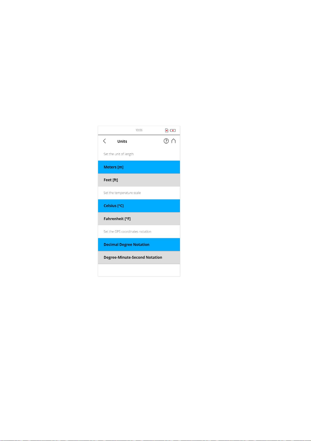
6.5.5 Setting the Unit of Length and the Temperature Scale
You can change the units scale under Home > Manage > General Settings >
Units.
Figure 6-20: Change Unit of Length
Lengths will be displayed by the controller software either in meters or in feet.
Select the favored unit of length by tapping the corresponding button.
Temperatures will be displayed either in Celsius or in Fahrenheit scale. Select
the favored temperature scale by tapping the corresponding button.
GPS coordinates are either displayed in decimal degree notation (e.g.
+34.9823450 °E) or in degree-minute-second notation (e.g. 34º 58' 56.44'' E).
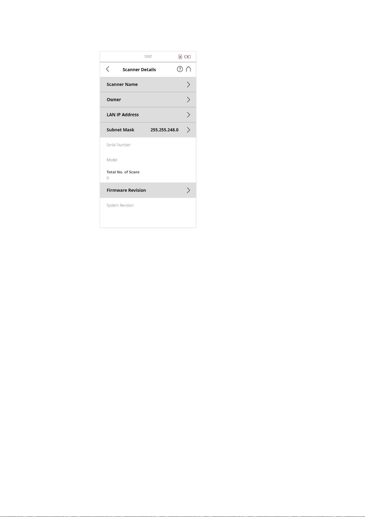
6.5.6 Entering Scanner Information
You can specify a scanner name and the owner of the FARO Laser Scanner.
Starting from the Home screen, go to
Scanner Details.
Chapter 6: Getting Started
Home > Manage > General Settings >
37
Page 43
FARO®Laser Scanner Manual
Figure 6-21: Scanner Details
Scanner name - Tap to change the name of the scanner.
Owner - Tap to enter the name of the company or person owning the scanner.
For more information, see
6.6 Scanning
This chapter will give you a brief description on how to set the scanning
parameters in order to capture your first scans. Normally, you would provide
and enter project information before starting with your scan project. This will
be described later. For more information, see
page 68.
6.6.1 Setting the Scanning Parameters
(Home > Parameters)
Scanning parameters like resolution, quality or the scanning angles are the
parameters used by the scanner for recording the scan data.There are two
ways to set the scanning parameters: by changing them manually or by
selecting a scan profile which is a predefined set of scanning parameters.
Scanner Details on page 99.
Scan Projects and Clusters on
When selecting a scan profile, its settings will overwrite the scanning
parameters.
38
Chapter 6: Getting Started
Page 44
FARO®Laser Scanner Manual
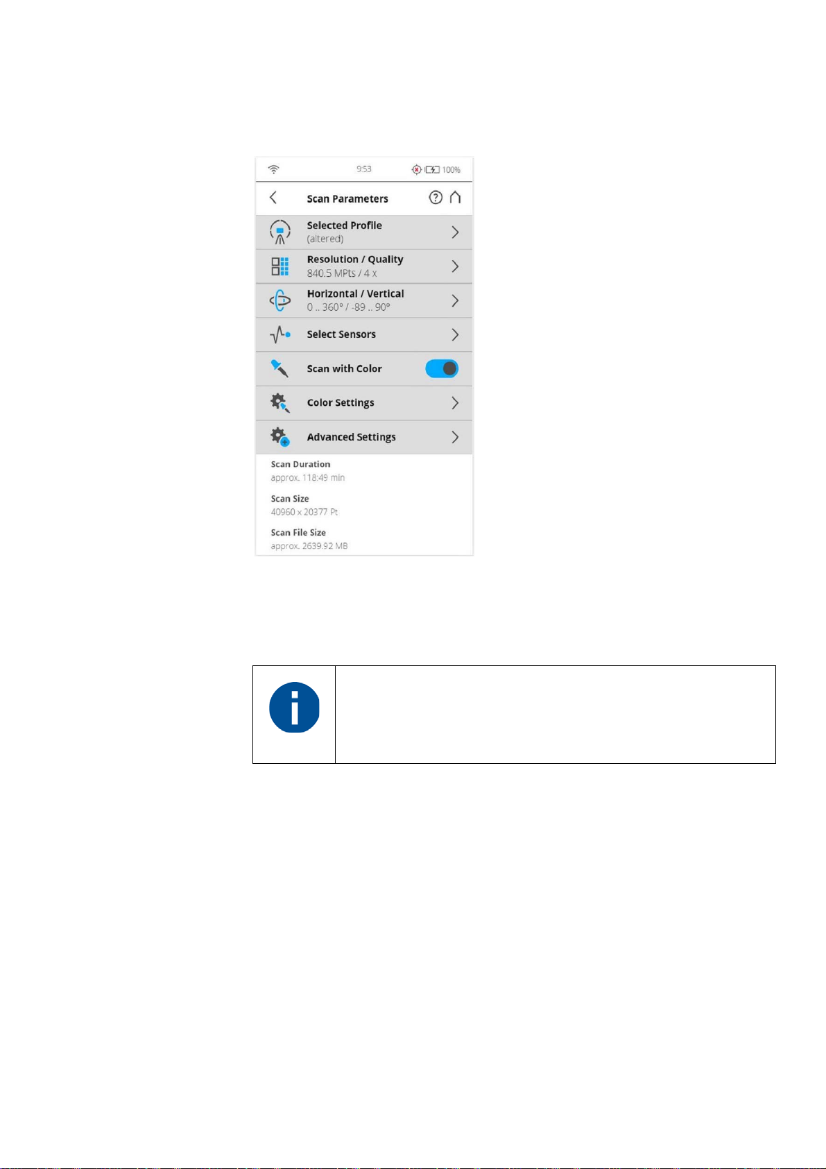
To choose a predefined scan profile or to change the scanning parameters tap
the Parameters button.
Figure 6-22: Change the Scan Parameters
Selected Profile - Shows the name of the selected scan profile. Tap to select
a scan profile. If the scanning parameters differ from the selected profile,
altered is appended to its name.
Selecting a predefined scan profile overwrites all current
scanning parameters with the settings of the selected scan
profile.
Additionally, you may edit the scanning parameters individually by changing
the following settings:
Resolution and Quality - Displays the selected resolution in megapoints and
the selected quality. Tap the button to change these values.
Horizontal and Vertical Scan Range - Displays the scan range with the
horizontal and the vertical start and end angles in degrees. Tap to adjust them.
Select Sensors - Opens the screen to enable or disable the automatic use of
the data of the built-in sensors for the scan registration in SCENE.
Chapter 6: Getting Started
Scan with Color - Switch colored scan recording on or off. If switched on, the
scanner will also take color photos of the scanned environment with the
integrated color camera. These photos will be taken right after the laser scan
39
Page 45
FARO®Laser Scanner Manual
and will be used in the point cloud processing software SCENE to
automatically colorize the recorded scan data.
Color Settings - Shows the current exposure metering mode used for taking
the color photos. Tap to change the exposure metering mode.
Advanced Settings - Enable or disable the Clear Contour and Clear Sky
filters. Enable or disable the Far Distance.
Scan Size [Pt] - Shows the size of the scan in points horizontally x vertically.
The vertical size may only be changed by setting a new resolution or by
changing the scan area angle.
Scan Duration, Scan File Size - Expected scan time and file size in
Megabytes according to the chosen settings including pre and post
processing, resolution, selected exposure metering, scan area, quality value,
and scan range. Please note that the values shown here are approximate
values.
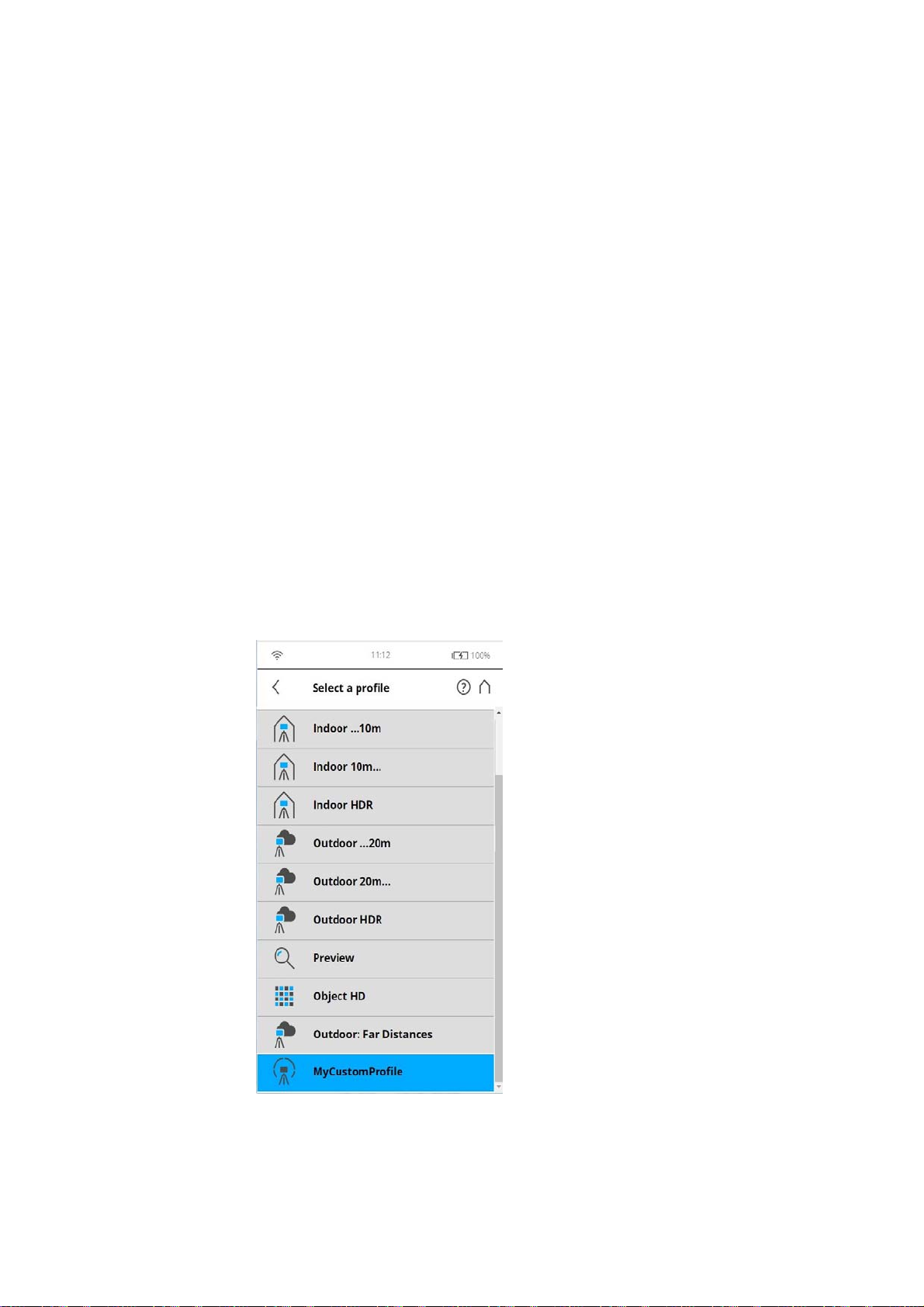
Selecting a Scan Profile
(Home > Parameters > Selected Profile)
Prior to capturing a scan, you can select a scan profile that fits the needs of
the scene and the desired scan quality.
Figure 6-23: Select a Profile
40
Chapter 6: Getting Started
Page 46
FARO®Laser Scanner Manual
This view shows a list of all available scan profiles. This list contains factory
predefined profiles that are read-only and custom profiles that can be created
and manipulated under Manage > Profiles.
See
Factory Settings on page 108 for an overview of the available factory
predefined scan profiles. For more information, see
Selected Profile on
page 60.
Select a profile by tapping the corresponding button. The selected profile will
be highlighted.
Setting Resolution and Quality
(Home > Parameters > Resolution / Quality)
Chapter 6: Getting Started
Figure 6-24: Change Scan Resolution and Quality
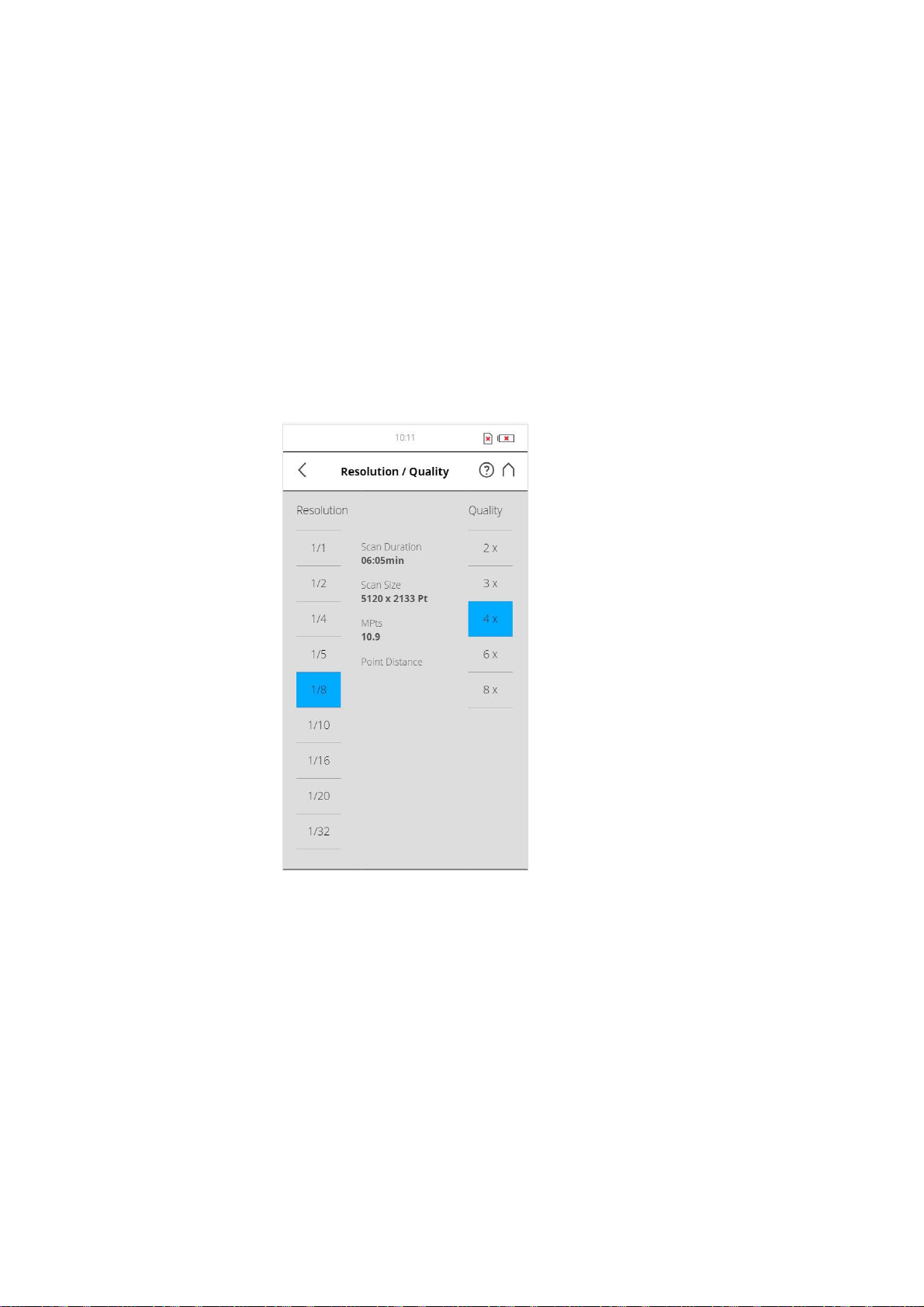
Resolution The resulting scan resolution. You can choose among 1/1, 1/2,
1/4, 1/5, 1/8, 1/10, 1/16, 1/20 and 1/32.
Quality Affects the quality of the scan and the scanning time at constant scan
resolutions. It allows the user to balance the needs of quality and speed with
one simple slider. Moving the slider up reduces the noise in the scan data and
thus increases the scan quality that results in an increased scanning time.
Moving the slider down reduces the scanning time and increases the
efficiency of your scan project. The Quality slider sets quality levels either
through diverse measurement rates or by applying additional noise
compression.
41
Page 47
FARO®Laser Scanner Manual
The resulting Scan Duration, vertical and horizontal scan points (Scan Size
[Pt]), as well as the resulting scan size in megapoints (MPts) will be displayed
in the middle of the view. Point Distance [mm/10m] / [in/30ft] is the distance
between the captured scan points in mm (in) in a scan distance of 10 meters
(30 ft).
If you plan to capture several scans from the same position (with different
resolutions) and if it is important that these scans have the same horizontal
start angle, then you should neither switch off the scanner nor change the
quality between the recordings of these scans.
Setting the Scan Range
(Home > Parameters > Horizontal / Vertical)
Figure 6-25: Setting the Scan Range
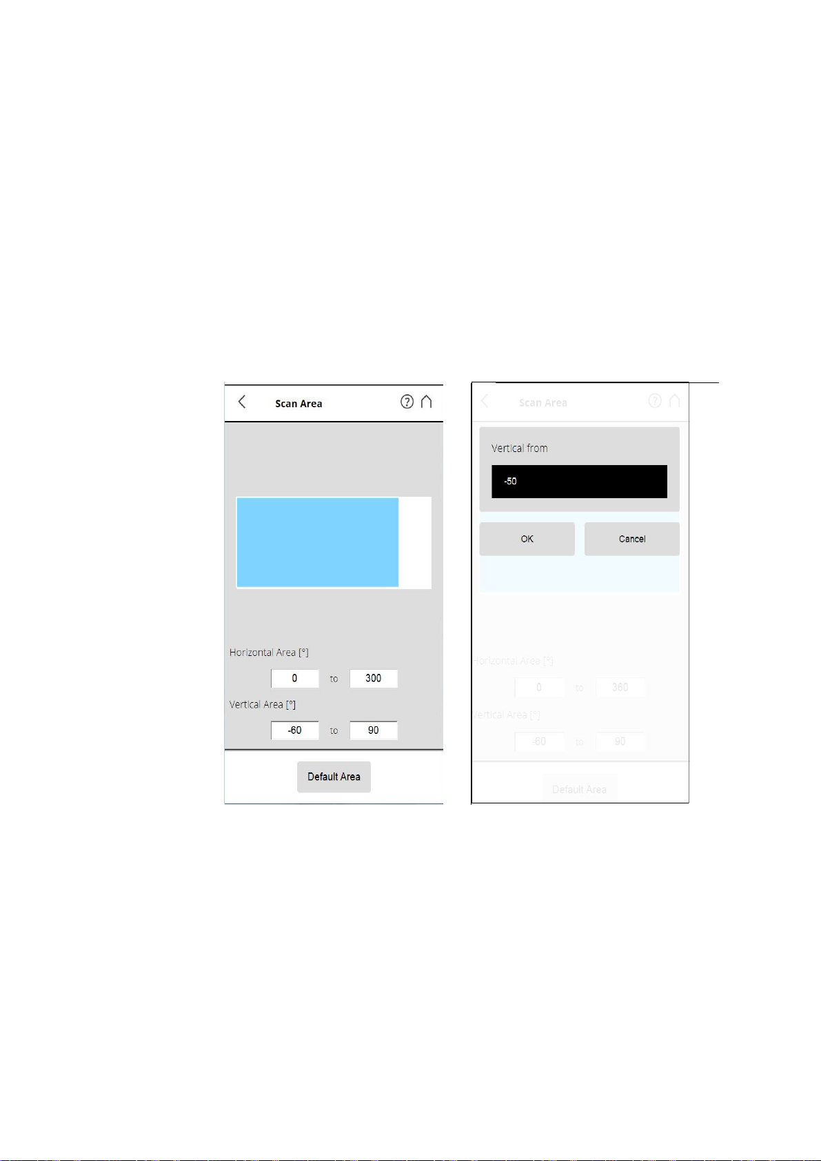
Vertical area - The size of the vertical scan area in degrees. Tap the fields to
enter the values of the vertical start angle and vertical end angle.
Horizontal area - The size of the horizontal scan area in degrees. Tap the
fields to enter the values of the horizontal start angle and horizontal end angle.
Default Area button - Tap to reset the values to the default scan area (vertical
from -60° to 90° and horizontal from 0° to 360°).
The rectangle in this view illustrates the full scan area. If there are scans on
the inserted SD card, the preview picture of the last recorded scan is
42
Chapter 6: Getting Started
Page 48
FARO®Laser Scanner Manual
displayed. If there is no preview picture available, a grid is displayed, where
the space between the horizontal and vertical lines is equivalent to 30°. The
highlighted rectangle illustrates the selected scan area.
Selecting the Sensors
(Home > Parameters > Select Sensors)
Figure 6-26: Selecting the Sensors
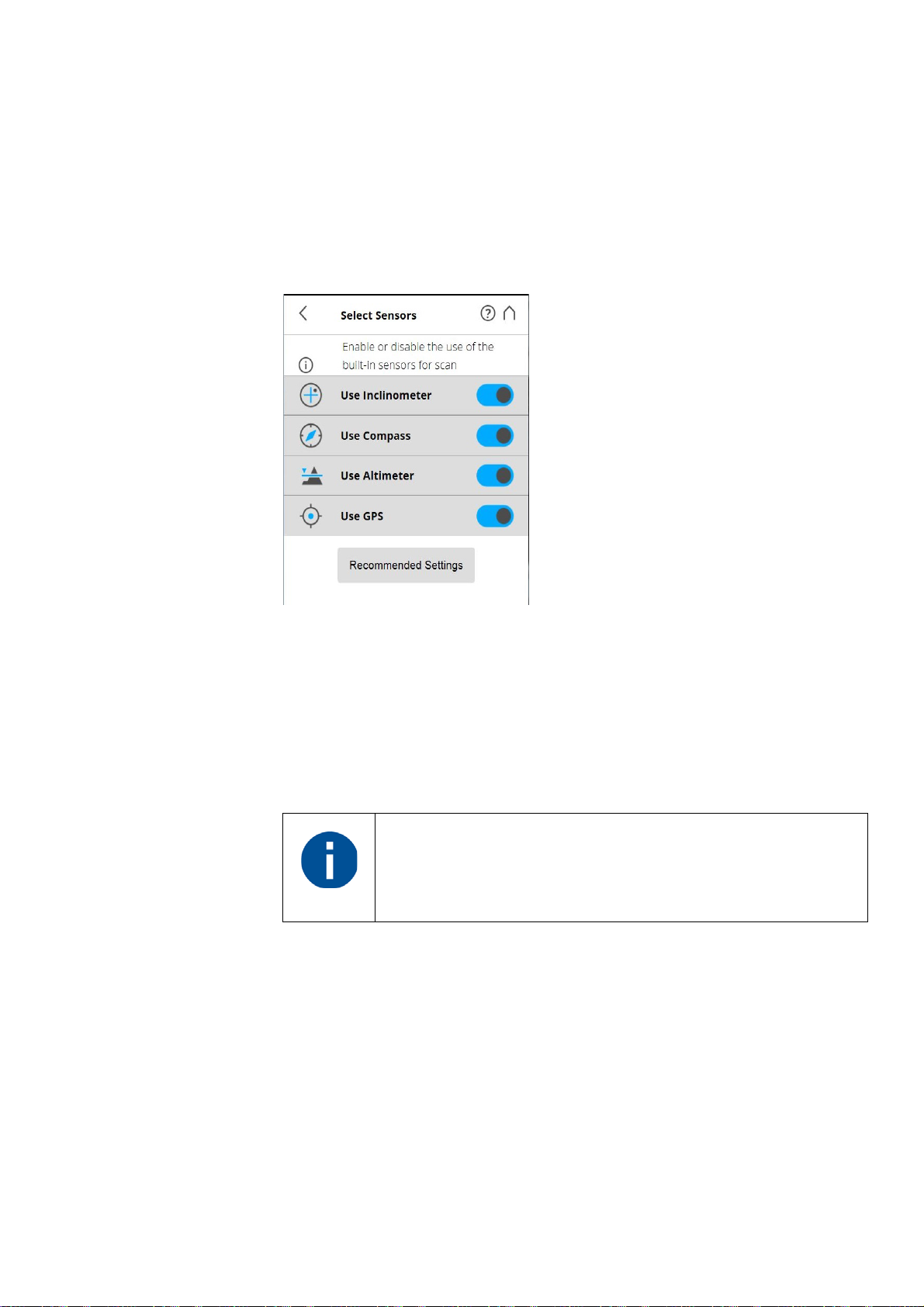
Use Inclinometer
- Enable or disable the automatic use of the inclination
measurement of the built-in dual axis compensator (inclinometer) for the scan
registration in SCENE. However, regardless of your setting, the data of this
sensor is always measured and attached to each scan. If the use of the
inclinometer data is switched ON, it will automatically be used to register the
scans in SCENE; if it is switched off, the data will be ignored. You can still
change this behavior later in SCENE. See the SCENE user manual for more
information.
To get the most reliable data from the dual axis compensator,
make sure that the scanner‘s inclination is less than 2°. For
more information, see
Inclinometer (Dual Axis Compensator)
on page 82.
Use Compass
- Enable or disable the automatic use of the data of the built-in
compass for the scan registration in SCENE. The data of the compass is
always measured and attached to each scan during scanning and will
automatically be used for the scan registration, if this button is switched to ON.
For more information, see
Compass on page 84.
Chapter 6: Getting Started
Use Altimeter
- Enable or disable the automatic use of the altimeter data for
the scan registration in SCENE. Just like with the inclinometer, the data of the
altimeter is always measured and attached to each scan during scanning and
will automatically be used for the scan registration, if this button is switched to
ON. You may want to enter a reference height before starting your scan
project. This reference height will then act as basis for all the measurements
43
Page 49
FARO®Laser Scanner Manual
made by the altimeter. You will find the altimeter settings under Manage >
Sensors > Altimeter. For more information, see
Altimeter on page 86.
Use GPS - Turn the GPS sensor ON or OFF. Unlike the other sensors, the
GPS data is only recorded during scanning and will thus only be available for
scan registration in SCENE if this button is switched to ON. For more
information, see
GPS on page 85.
Recommended Settings button to enable the use of all sensors.
Color Settings
(Home > Parameters > Color Settings)
Figure 6-27: Color Settings
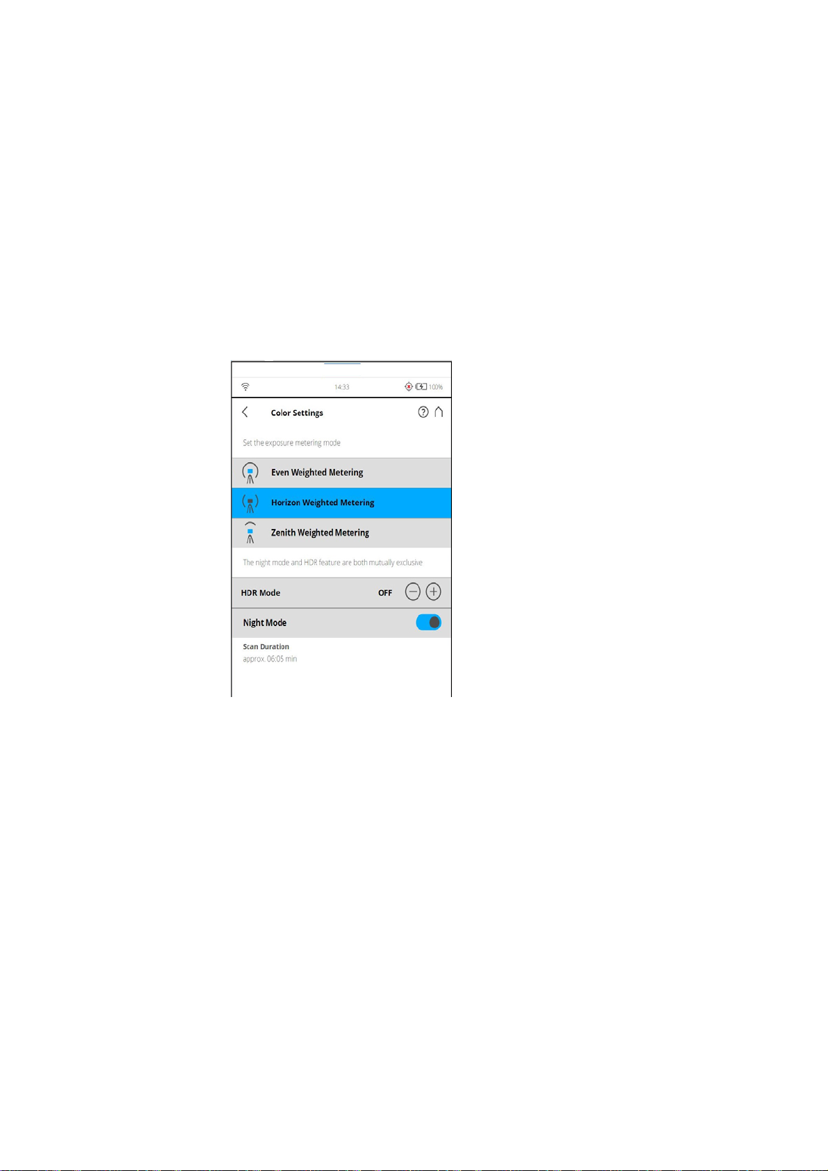
Set the exposure metering mode - Set the way in which the integrated color
camera determines the exposure for taking the color photos (if colored scan
recording is switched on).
Even Weighted Metering - To determine the exposure settings, the camera
will use the light information coming from the entire scene and averages
without giving weighting to a particular area.
Horizon Weighted Metering - With horizon weighted metering mode, the
camera will use the light information coming from the horizon to determine its
exposure setting. This mode is commonly used in scenarios with bright light
coming from directly above (e.g. indoors with bright ceiling lighting or outdoors
with bright sunlight)
Horizon weighted metering
If the vertical scan area is limited, then the area used to determine the
exposure (exposure metering area) might move away from the horizon. This is
44
Chapter 6: Getting Started
Page 50
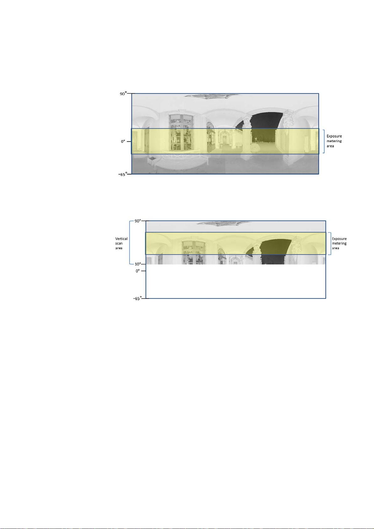
FARO®Laser Scanner Manual
the case if the vertical start angle is set to a value > -30° or if the vertical end
angle is set to a value < 30°. The exposure metering area will then be moved
up or down and set to the center of the remaining vertical scan area. The
following figures illustrate this behavior.
Figure 6-28: Exposure metering area (highlighted yellow) for the full vertical
scan area
Figure 6-29: Exposure metering area for a limited vertical scan area set to e.g.
10° to 90°
Zenith Weighted Metering - With zenith weighted metering, the camera will
use the light information coming from above the scanner to determine its
exposure setting. Use this mode if there is very bright light coming from e.g.
windows and if you want to achieve the most correct balance of light and
exposure for objects at the ceiling of building.
HDR mode The High Dynamic Range (HDR) imaging method merges images captured
with different exposure settings to one image with a greater dynamic range of
luminosity.
Scanning with HDR capturing
Chapter 6: Getting Started
45
Page 51
FARO®Laser Scanner Manual
Set the HDR capturing by tapping the + or - button from 2x to 5x. This setting
corresponds to the exposure levels. If no option is selected, then OFF
selection is displayed.
When HDR is enabled, the larger number of captured images
will result in a longer capturing time. The processing time will
be longer in SCENE.
Night Mode Select the night mode to improve the quality of the color photos in relatively
dark lighting conditions. The image noise will be reduced in low light
situations. However, enabling the night mode will increase the scan duration
significantly.
The best scanning results can be achieved if Night Mode is
enabled along with Horizon Weighted Metering or Zenith
Weighted Metering.
However, very dark lighting conditions may lead to a poor
picture quality even if night mode is activated. This can lead to
grainy images and other artifacts.
Advanced Settings
Figure 6-30: Advanced Scanning Settings
Clear Contour - Enables the dynamic contour filter. This hardware filter will
remove incorrect measurements at the edges of objects during scanning, due
to duplicate scan points.
Clear Sky - Enables the dynamic sky filter. During scanning, this hardware
filter will remove scan points resulting from scanning empty spaces in the sky.
Distance Range - The Distance Range setting configures the scanner to
increase the quality of the points captured at specified distances.
Normal - Select this option when scanning under normal light conditions.
Near - Select this option to scan near objects accurately.
46
Chapter 6: Getting Started
Page 52
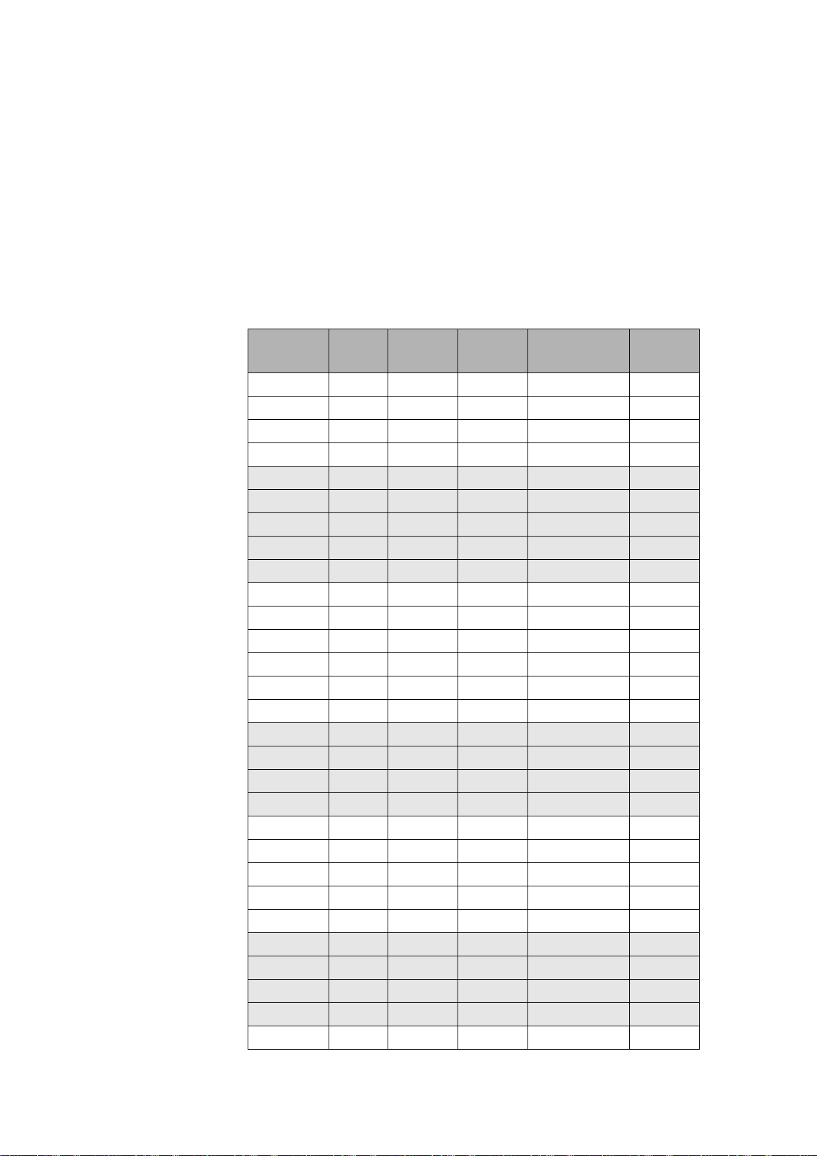
FARO®Laser Scanner Manual
Far Distances - Select this option when scanning outer spaces where the
scan surfaces are located at distances greater than 20 meters from the
scanner position. This setting is not recommended when scanning indoors.
Recommended Settings - Enables the Clear Contour and Clear Sky filters.
Disables Far Distance Optimization.
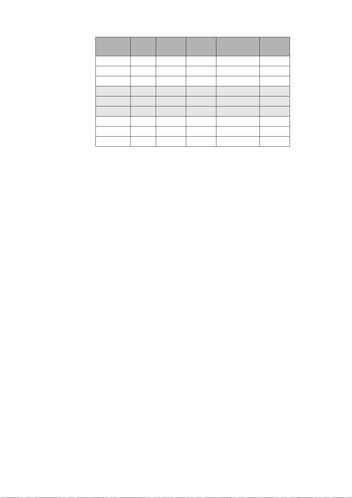
6.6.2 Scanning Parameters Overview
The following table shows the scanning parameters and net scan time for all
the resolution and quality settings that are available.
Resolution
1/1 1x 699.1 0:15:19 1.5mm/10m 40,960
1/1 2x 699.1 0:29:38 1.5mm/10m 40,960
1/1 3x 699.1 0:58.16 1.5mm/10m 40,960
1/1 4x 699.1 1:55:32 1.5mm/10m 40,960
1/2 1x 174.8 0:04:35 3.1mm/10m 20,480
1/2 2x 174.8 0:08:09 3.1mm/10m 20,480
1/2 3x 174.8 0:15:19 3.1mm/10m 20,480
1/2 4x 174.8 0:29:38 3.1mm/10m 20,480
1/2 6x 174.8 1:55:32 3.1mm/10m 20,480
1/4 1x 43.7 0:01:54 6.1mm/10m 10,240
1/4 2x 43.7 0:02:47 6.1mm/10m 10,240
1/4 3x 43.7 0:04:35 6.1mm/10m 10,240
1/4 4x 43.7 0:08:09 6.1mm/10m 10,240
1/4 6x 43.7 0:29:38 6.1mm/10m 10,240
1/4 8x 43.7 1:55:32 6.1mm/10m 10,240
1/5 2x 28.0 0:02:09 7.7mm/10m 8,192
1/5 3x 28.0 0:03:17 7.7mm/10m 8,192
Quality Mio. Pts
(full scan)
Net Scan
Time
Point Distance pt/360°
Chapter 6: Getting Started
1/5 4x 28.0 0:05:35 7.7mm/10m 8,192
1/5 6x 28.0 0:19:20 7.7mm/10m 8,192
1/8 2x 10.9 0:01:27 12.3mm/10m 5,120
1/8 3x 10.9 0:01:54 12.3mm/10m 5,120
1/8 4x 10.9 0:02:47 12.3mm/10m 5,120
1/8 6x 10.9 0:08:09 12.3mm/10m 5,120
1/8 8x 10.9 0:29:38 12.3mm/10m 5,120
1/10 3x 7.0 0:01:34 15.3mm/10m 4,096
1/10 4x 7.0 0:02:09 15.3mm/10m 4,096
1/10 6x 7.0 0:05:35 15.3mm/10m 4,096
1/10 8x 7.0 0:19:20 15.3mm/10m 4,096
1/16 3x 2.7 0:01:13 24.5mm/10m 2,560
47
Page 53
FARO®Laser Scanner Manual
6.6.3 Starting a Scan
Resolution
1/16 4x 2.7 0:01:27 24.5mm/10m 2,560
1/16 6x 2.7 0:02:47 24.5mm/10m 2,560
1/16 8x 2.7 0:08:09 24.5mm/10m 2,560
1/20 4x 1.7 0:01:17 30.7mm/10m 2,048
1/20 6x 1.7 0:02:09 30.7mm/10m 2,048
1/20 8x 1.7 0:05:35 30.7mm/10m 2,048
1/32 4x 0.7 0:01:07 49.1mm/10m 1,280
1/32 6x 0.7 0:01:27 49.1mm/10m 1,280
1/32 8x 0.7 0:02:47 49.1mm/10m 1,280
Quality Mio. Pts
(full scan)
Net Scan
Time
Point Distance pt/360°
Remember that the scanner is turning and the mirror unit is rotating with high
speed. Ensure that the scanner can move freely and that no objects can touch
the mirror unit.
Start the scan by tapping on the Start Scan button on the Home screen of the
controller software
If there is not enough space on the SD card, you will be warned and the
scanner will refuse to scan. In this case, please remove scan data from the
memory card or insert a new card and try again.
When the scan process starts, the laser of the scanner will be switched ON
and the scanning view will be displayed. The scanner's LEDs blink red as long
as the laser of the scanner is switched ON. During scanning, the scanner
rotates clockwise by 180°. If you are scanning with color, the scanner will
continue to turn to 360° to take the pictures. The executed processing steps
are displayed in the status bar of the scanning screen, the scan progress is
indicated by the progress bar.
48
Chapter 6: Getting Started
Page 54
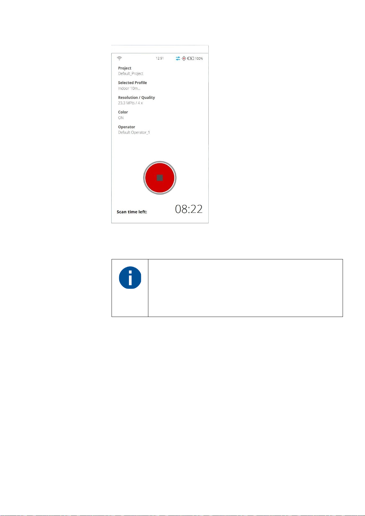
FARO®Laser Scanner Manual
Figure 6-31: Scanning View
To stop a scan, touch the Stop Scan button in the scanning view. You will then
be asked to keep or delete the incomplete scan.
After having completed scanning and capturing the pictures,
depending on environmental conditions, the scanner may make
another full turn to capture inclination data. It is important NOT
to move the scanner while it is capturing the inclination data, or
the inclination data of the scan may be inaccurate and may not
be usable for the scan registration.
As soon as the entire scanning process is complete, the scanner plays a
notification sound (if not turned off in the settings) and a new screen appears
with a preview picture of the captured scan. Now, you may move the scanner
to the next scan position and start a new scan.
Chapter 6: Getting Started
49
Page 55
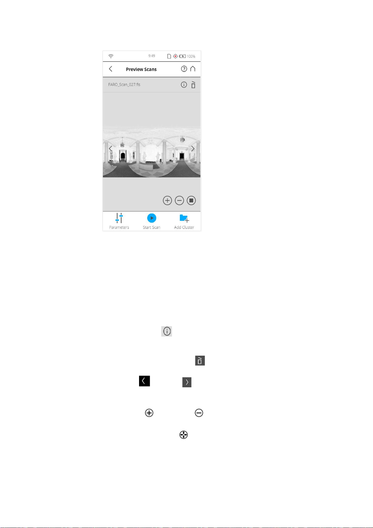
FARO®Laser Scanner Manual
Figure 6-32: Scan Preview
The scan preview shows a grayscale picture of the captured scan to verify the
scan itself and to check if all objects (e.g., targets) are clearly visible. This
preview does not show color.
Parameters button - Tap to change the scanning parameters for the next
scans.
Start Scan button - Start a scan.
Tap the Info button in the scan preview to view the scan properties.
Resume Scan button - Resumes the previous scan. Displayed only when a
scan is paused. Delete button - Delete the viewed scan file.
Use the left and right arrow buttons to browse through already
captured scans.
Use the plus and minus buttons to zoom in or out.
The Reset Zoom button is only visible when you zoom into the scan
picture. With this button the scan picture can be zoomed back to its original
size.
When zoomed in you can move the zoomed picture by dragging it with your
fingers in any direction.
50
Chapter 6: Getting Started
Page 56
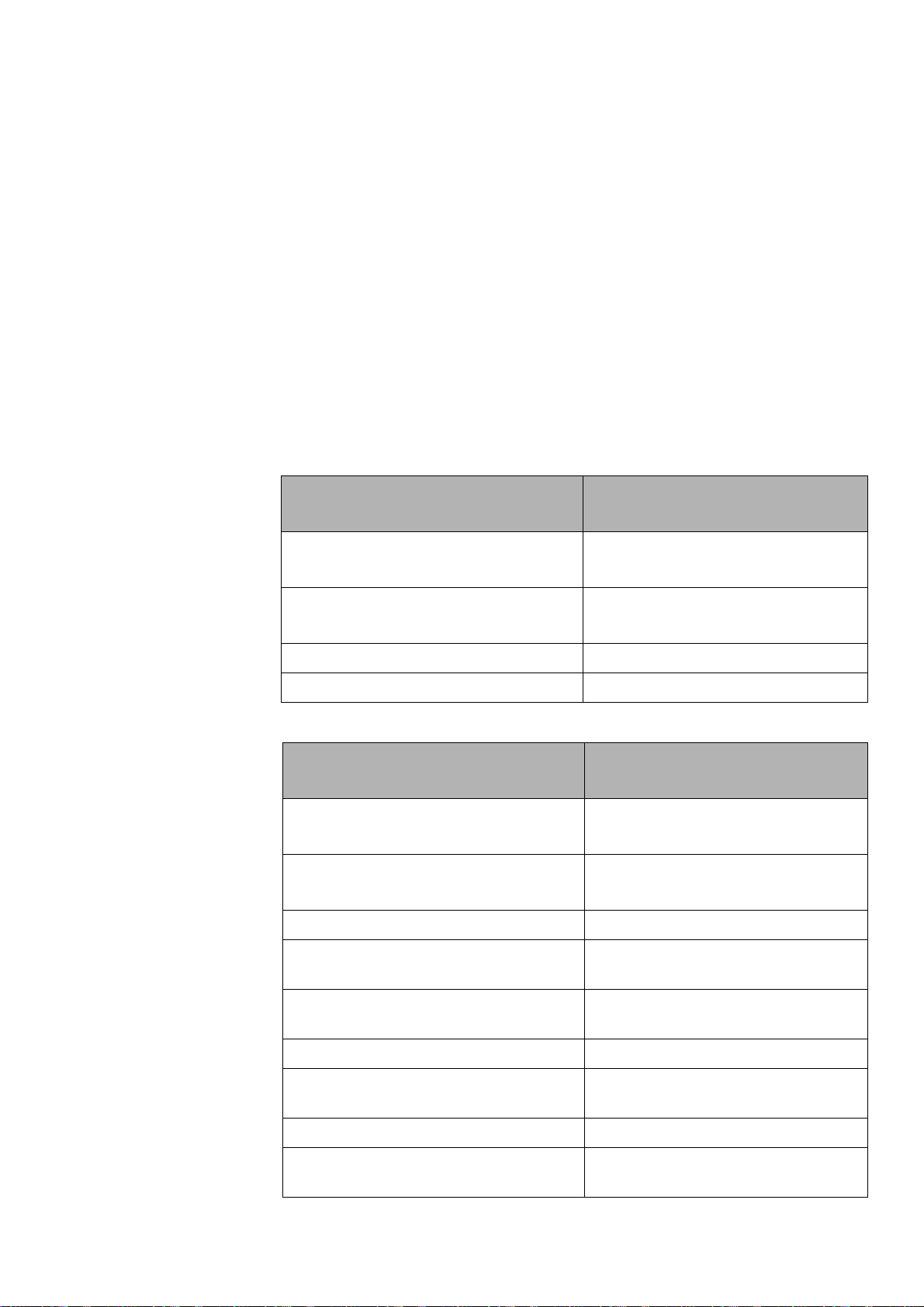
FARO®Laser Scanner Manual
6.7 LED Behavior
The Inclination in degrees is displayed in the header bar
The following inclination warning message is displayed if the current
inclination of the scanner is above 5°.
Strong scanner inclination
Inclination of the scanner is not within +/- 5°. This could result in slightly
inexact scan measurements.
Try to position the scanner so that its inclination is between +/-5°.To get
reliable measurements from the built-in dual axis compensator you should set
up the scanner with an inclination less than 5° before starting your next scan.
For this, you may use either a bubble inclinometer at the tripod or the
inclinometer screen. Tap this button to get to the inclinometer screen.
Scanner Status LED at Power ON/OFF button
Scanner off, external power supply not
off
connected
Regular boot process flashes blue and fast
Battery operation constantly blue
Power On/Off flashes blue
Scanner Status LED next to the battery
Scanner off, external power supply not
off
connected
Regular boot process flashes blue and fast
Battery operation constantly blue
Low battery operation at battery state
flashes blue
less than 10%
Chapter 6: Getting Started
Low battery operation at battery state
flashes violet
less than 5%
AC adapter operation only (no battery) green
Battery charging, state of charge is
cyan
above 90% (charge done)
Battery charging orange
Battery charging, state of charge less
flashes orange
than 10%
51
Page 57
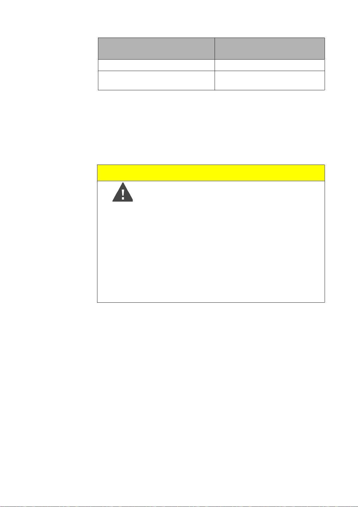
Scanner Status LED next to the battery
Battery charging, deep discharge flashes red
FARO®Laser Scanner Manual
Unknown power source. Battery and
AC adapter are not detected
6.8 Shutting Down the FARO Laser Scanner
To shut down the FARO Laser Scanner, press its Power On/Off button for 2
or 3 seconds or tap the Power button in the user interface drop-down list
under
FARO Laser Scanner has finished the shutdown process the LEDs will stop
blinking and you can safely remove the battery and the power supply.
Home. The top LEDs will start blinking blue. As soon as the
Caution
Damages to the scanner‘s internal PC and loss of
data.
Do not turn off the power of the FARO Laser Scanner
before the shut down cycle is complete.
The FARO Laser Scanner has an integrated PC with a
hard drive. This internal PC must be shut down before
turning off the power supply. If the power supply is
disconnected or switched off without the FARO Laser
Scanner being previously shut down, it may damage the
internal PC and might lead to a loss of data.
If the FARO Laser Scanner has not been shut down
properly, the next boot process could take more time as
usual as the FARO Laser Scanner might check its hard
disk for errors.
constantly red
Pressing and holding the button more than 10 seconds will switch the
FARO Laser Scanner off without shutting down. Please use this option only if
the FARO Laser Scanner does not shut down regularly because of a
malfunction.
6.9 Powering Off the FARO Laser Scanner
Once the FARO Laser Scanner has been completely shut down, remove the
battery and secure the equipment in protective cases.
1. Open the battery compartment cover.
2. Release the interlock mechanism of the charger to release the battery.
3. Remove the battery.
Close the battery compartment cover.
52
Chapter 6: Getting Started
Page 58

FARO®Laser Scanner Manual
53
Page 59
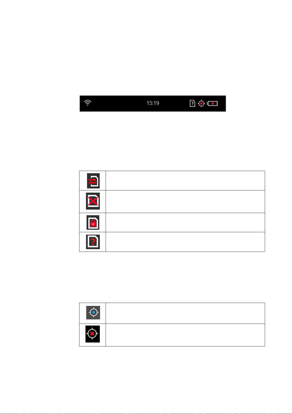
Chapter 7: Controller Software
7.1 General Elements
7.1.1 Status Bar
Figure 7-33: Status Bar
Clock - shows the current time of the scanner. See Setting the Dat e and
Time
on page 35 for information on how to change the date and time of the
scanner.
SD card status
FARO®Laser Scanner Manual
SD card is busy.
WLAN is turned on, and the signal strength is displayed.
GPS signal
Do not remove the SD card from the scanner while it is busy, otherwise you risk
corrupting the data on the card.
No SD card inserted.
SD card is write-protected. Remove write protection to be able to scan with this
card.
Unknown SD card inserted. The card cannot be read. This might be due to the
SD card being formatted in an unsupported file system. You should format the
SD card with the built in format function. See
GPS signal available.
SD Card on page 103.
No GPS signal, or vague position.
Battery - shows the status and charge state of the internal battery:
54
Chapter 7: Controller Software
Page 60
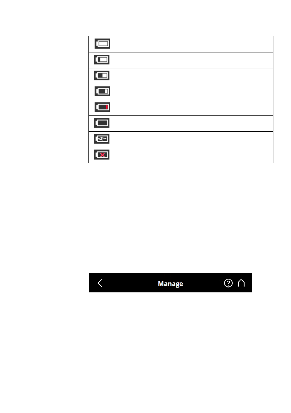
FARO®Laser Scanner Manual
Battery is fully charged.
Charge state > 75% and < 100%.
Charge state > 50% and < 75%.
Charge state > 25% and < 50%.
Charge state > 10% and < 25%, you should switch the batter as soon as
possible.
Battery is almost empty; FARO
within the next minutes.
Battery is charging.
No battery in the FARO®Laser Scanner.
®
Laser Scanner will automatically shut down
The exact charge state of the battery can be viewed under Home > Manage >
General Settings >
Power Management (see Power Management on
page 90).
7.1.2 Navigation Bar
If the charge state of the battery is below 25 percent, you will get a warning.
Please switch to the spare battery as soon as possible.
If the charge state of the battery reaches 10 percent, the FARO
®
Laser
Scanner will stop scanning and will automatically shut down.
Figure 7-34: Navigation Bar
Back - returns you to the previous screen.
The name of the screen that is currently shown.
Errors and Warnings - this button only appears if warning or errors are
present. Tapping the button opens a screen that informs about details of
the existent warnings or errors. See
Errors and Warnings on page 103.
Help - opens the online help of the currently active screen and provides
access to the User Manual. See
Online Help and Notifications on
page 111.
55
Chapter 7: Controller Software
Page 61
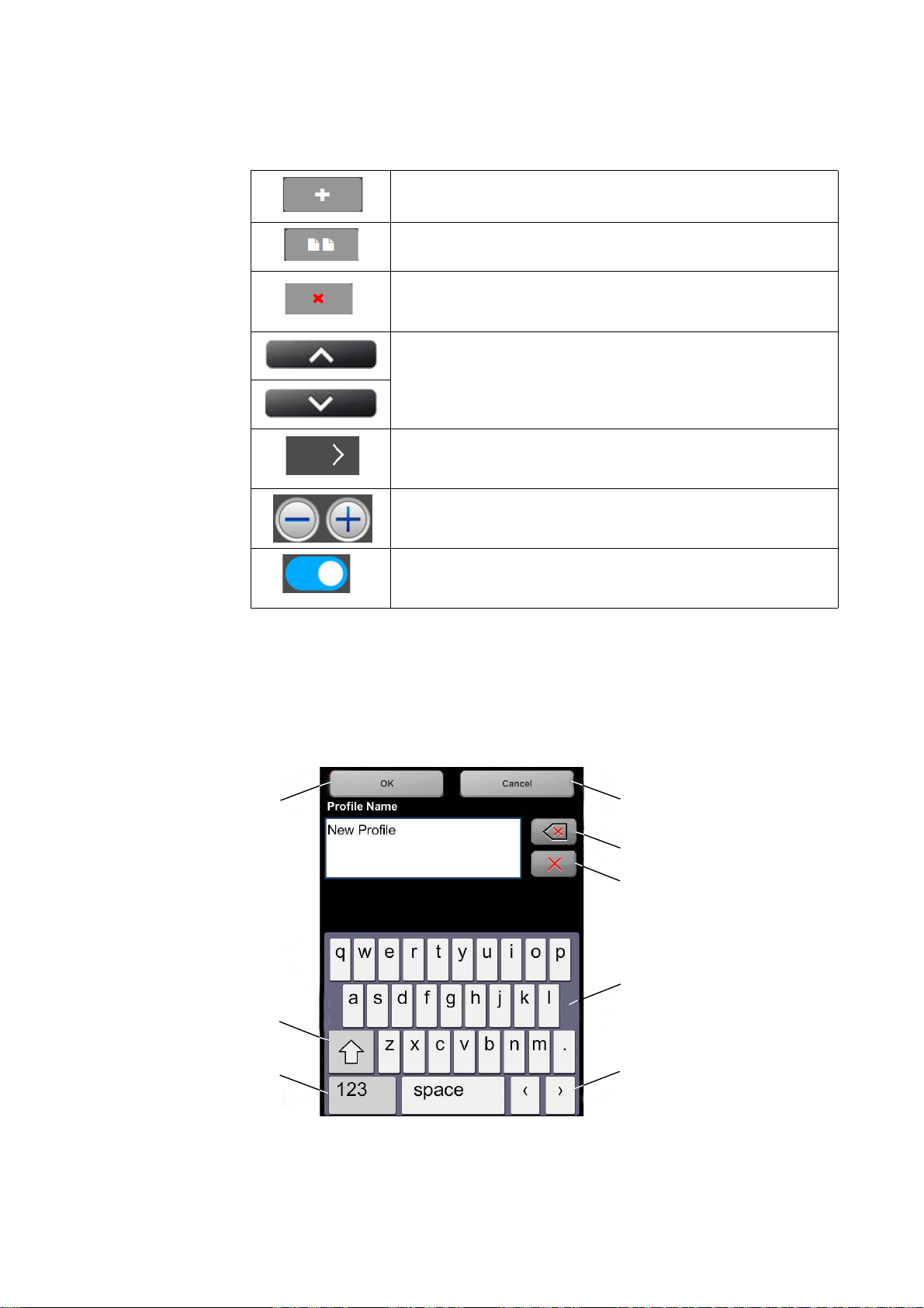
Home - returns you to the Home screen. See Home Screen on page 58.
7.1.3 Frequently Used Buttons
FARO®Laser Scanner Manual
Add button. Adds new scan profiles, projects or operators.
Duplicate button. Adds new scan profiles, projects or operators by
duplicating the selected list element.
Delete button. Deletes selected list elements, like projects, scan
profiles or operators. This button is grayed if the selected list element
can not be deleted.
Scroll up and down buttons. Appear on the bottom of the screen if the
content of a screen exceeds the screen height. Tap the button to scroll
the screen up or down.
A arrow on buttons indicates that this button opens a new screen with
further details or settings.
Decrease or increase a value by tapping one of these two buttons.
On/Off slider. Used to turn functions on or off. Here, the function is
turned on.
7.1.4 Context-Sensitive Keyboard
The context-sensitive keyboard is shown if an entry field requires an entry, for
example, to enter operator data or the name of the scan project.
Figure 7-35: Onscreen Keyboard
Shift key to toggle between capital and lower case letters
56
Chapter 7: Controller Software
Page 62
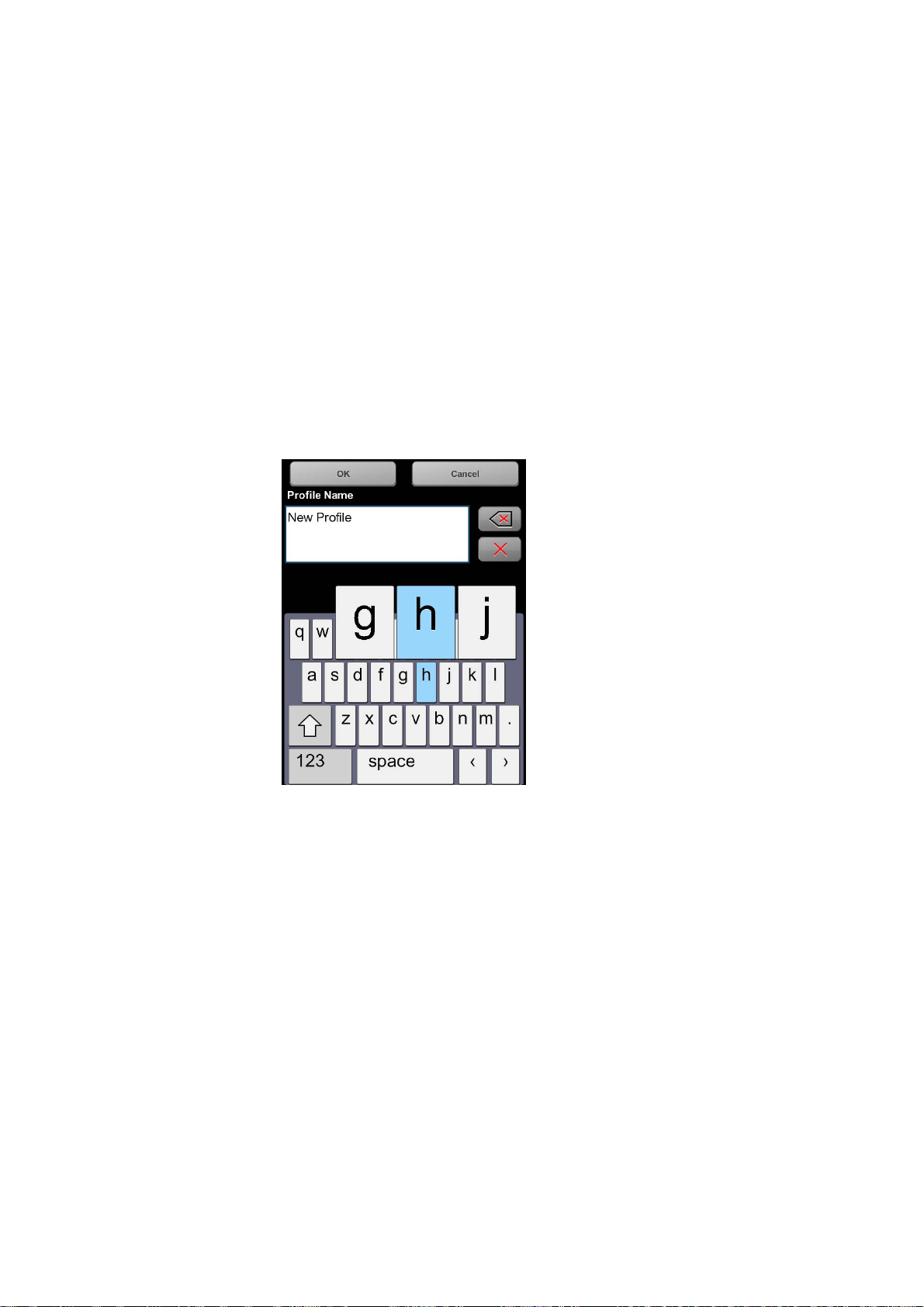
FARO®Laser Scanner Manual
Key to toggle keyboard between standard and special characters
Moves the cursor in the text field right or left
Delete key - deletes the complete text
Backspace
OK key - applies your input and returns to the previous screen
Cancel key - returns to the previous screen without applying your changes
Tapping on a character of the keyboard will enlarge it as well as its
neighboring characters. Select among the enlarged characters by
dragging your finger a bit to the right or to the left. The selected character
will be highlighted.
Chapter 7: Controller Software
Figure 7-36: Onscreen Keyboard
57
Page 63
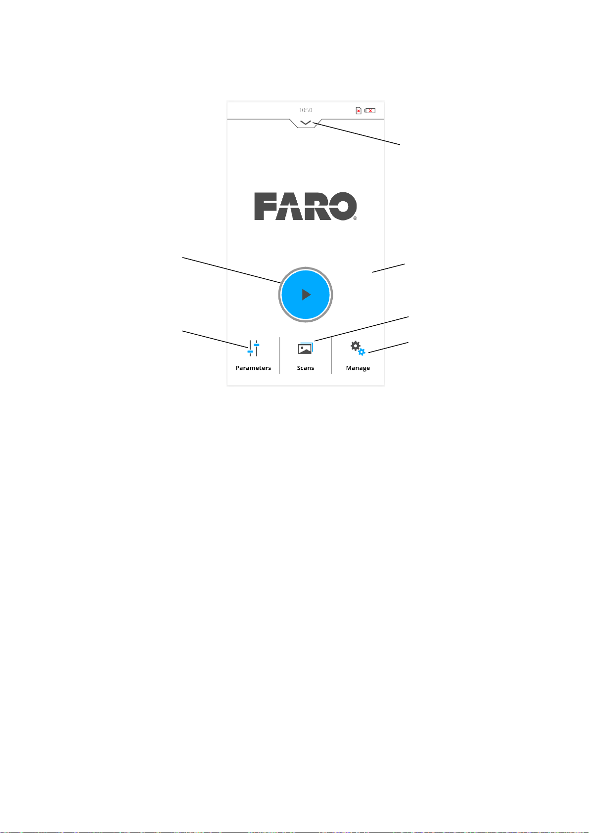
7.2 Home Screen
FARO®Laser Scanner Manual
Figure 7-37: Home Screen
Start Scan button - Starts a scan. See Starting a Scan on page 48.
Parameters button - Opens the dialog to select another scan profile and to
edit the current scanning parameters. For more information, see
the Scanning Parameters
Info box - Tap the arrow button underneath HOME to show or hide the info
on page 38.
Setting
box. The info box informs about the currently selected operator, project
and scan profile. It also shows information about the current scanning
parameters resolution in megapoints, quality, scan duration and color.
Add cluster button - Tap to add a cluster to the currently selected project.
View Scans button - Preview the scans that are stored on the SD card.
See
View Scans on page 109.
Manage button - Manage scan profiles, projects, operators and the
scanner. See
Manage on page 67.
58
Chapter 7: Controller Software
Page 64
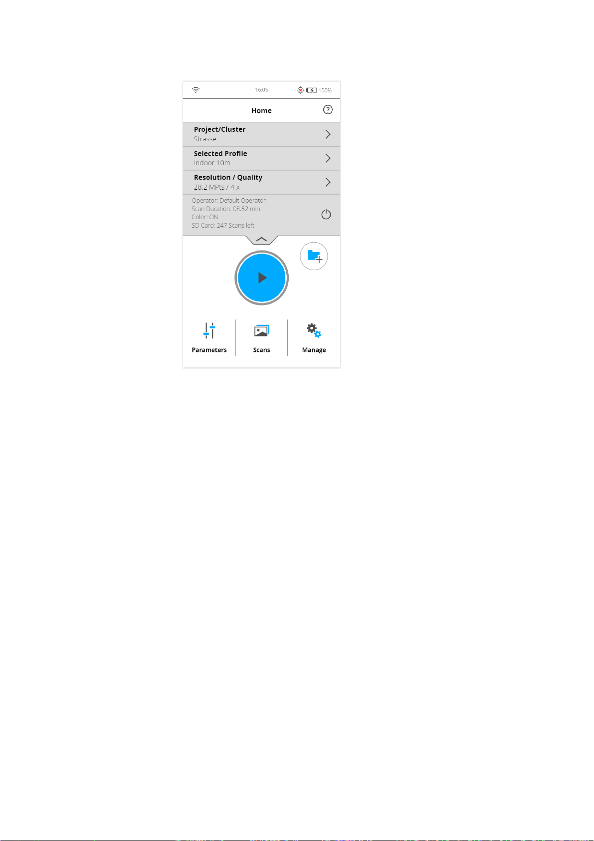
FARO®Laser Scanner Manual
Figure 7-38: Home Screen with Info Box
7.3 Scan parameters
Scanning parameters like resolution, quality or the scanning angles are the
parameters used by the scanner for recording the scan data.
There are two ways to set the scanning parameters:
• by changing them manually
• by selecting a scan profile which is a predefined set of scanning
To select a predefined scan profile or to change the scanning parameters, tap
the Parameters button on the Home screen.
parameters.
Chapter 7: Controller Software
59
Page 65
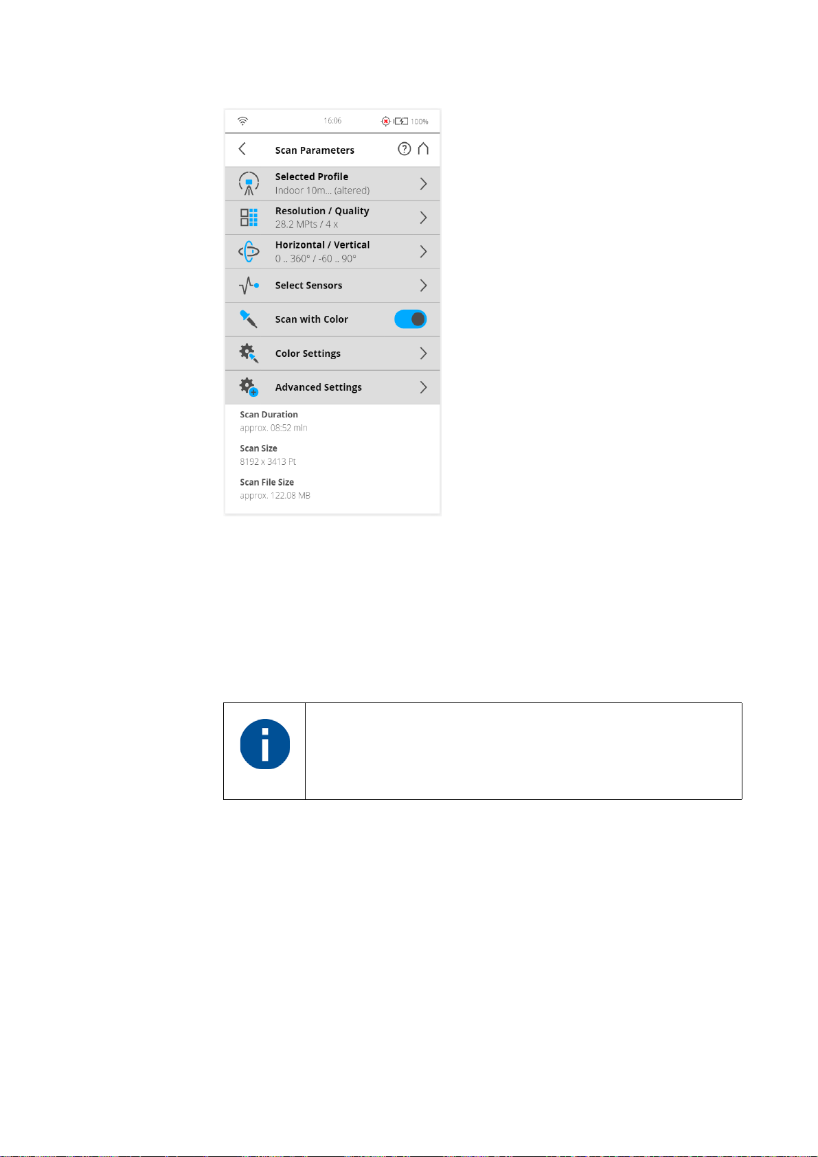
FARO®Laser Scanner Manual
Figure 7-39: Change the Scan Parameters
7.3.1 Selected Profile
Shows the name of the selected scan profile. Tap to select a scan profile. If the
scanning parameters differ from the selected profile, altered is appended to its
name.
Selecting a predefined scan profile overwrites all current
scanning parameters with the settings of the selected scan
profile.
60
Chapter 7: Controller Software
Page 66
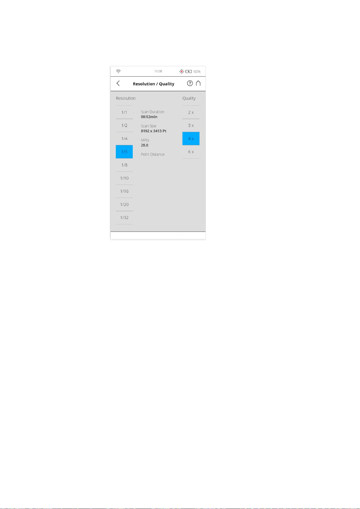
FARO®Laser Scanner Manual
7.3.2 Resolution and Quality
Figure 7-40: Scan Parameters, Resolution, and Quality
Displays the selected resolution in megapoints, and the selected quality. Tap
the button to change these values.
Chapter 7: Controller Software
61
Page 67
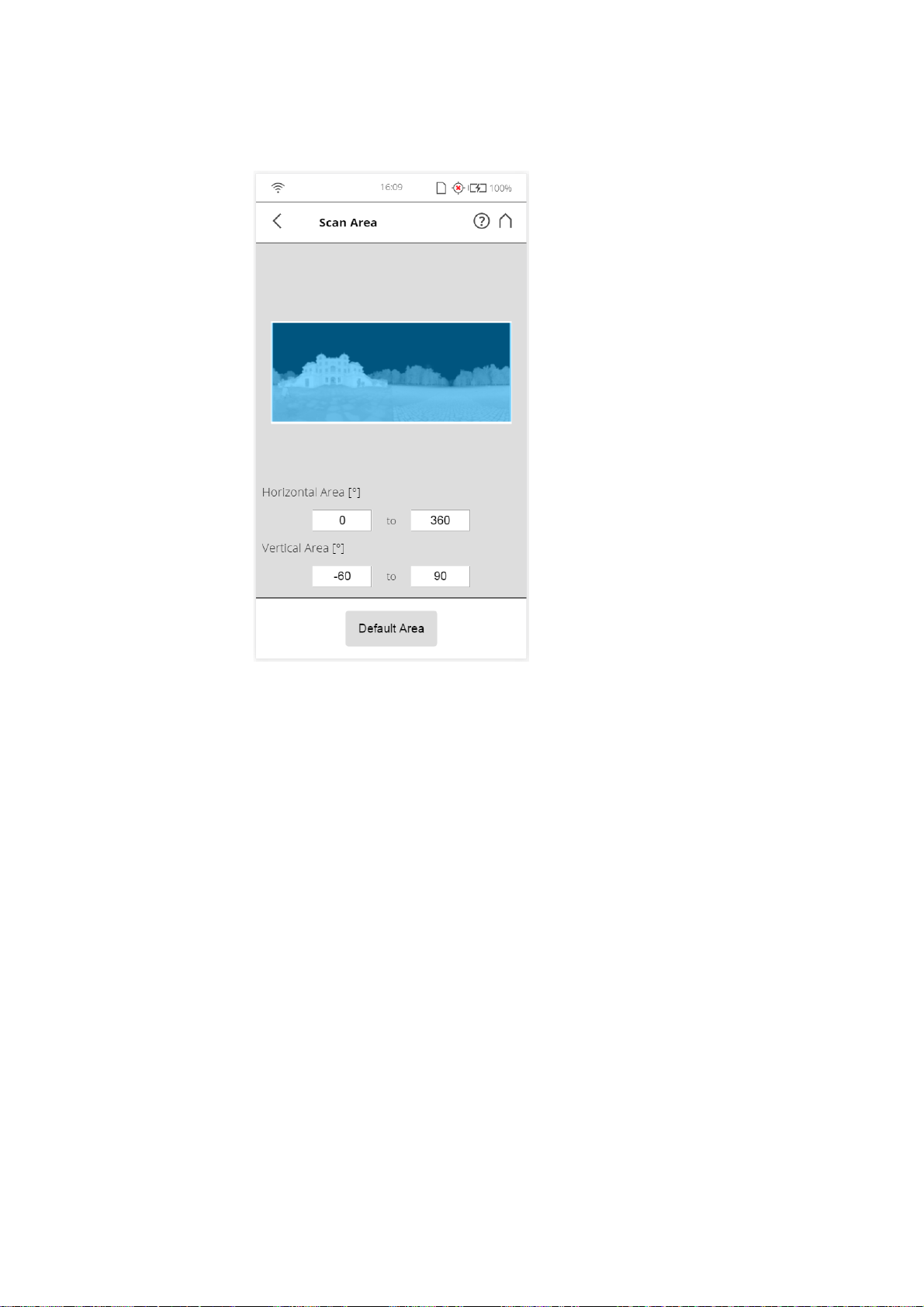
7.3.3 Horizontal and Vertical Scan Range
FARO®Laser Scanner Manual
Figure 7-41: Scan Parameters - Scan Area
Displays the scan range with the horizontal and the vertical start and end
angles in degrees. Tap to adjust them.
62
Chapter 7: Controller Software
Page 68
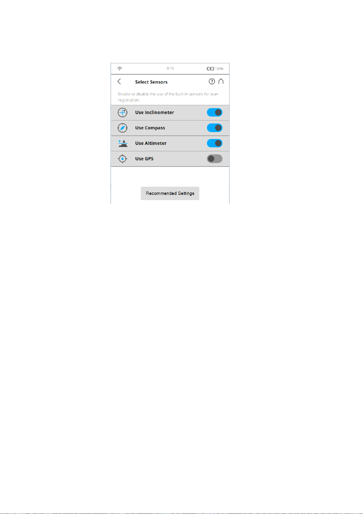
FARO®Laser Scanner Manual
7.3.4 Select Sensors
Figure 7-42: Scan Parameters - Select sensors
Opens the screen to enable or disable the automatic use of the data of the
built-in sensors for the scan registration in SCENE.
7.3.5 Scan with Color
Switch colored scan recording on or off. If switched on, the scanner will also
take color photos of the scanned environment with the integrated color
camera. These photos will be taken immediately after the laser scan and will
be used in the point cloud processing software SCENE to automatically
colorize the recorded scan data.
Chapter 7: Controller Software
63
Page 69
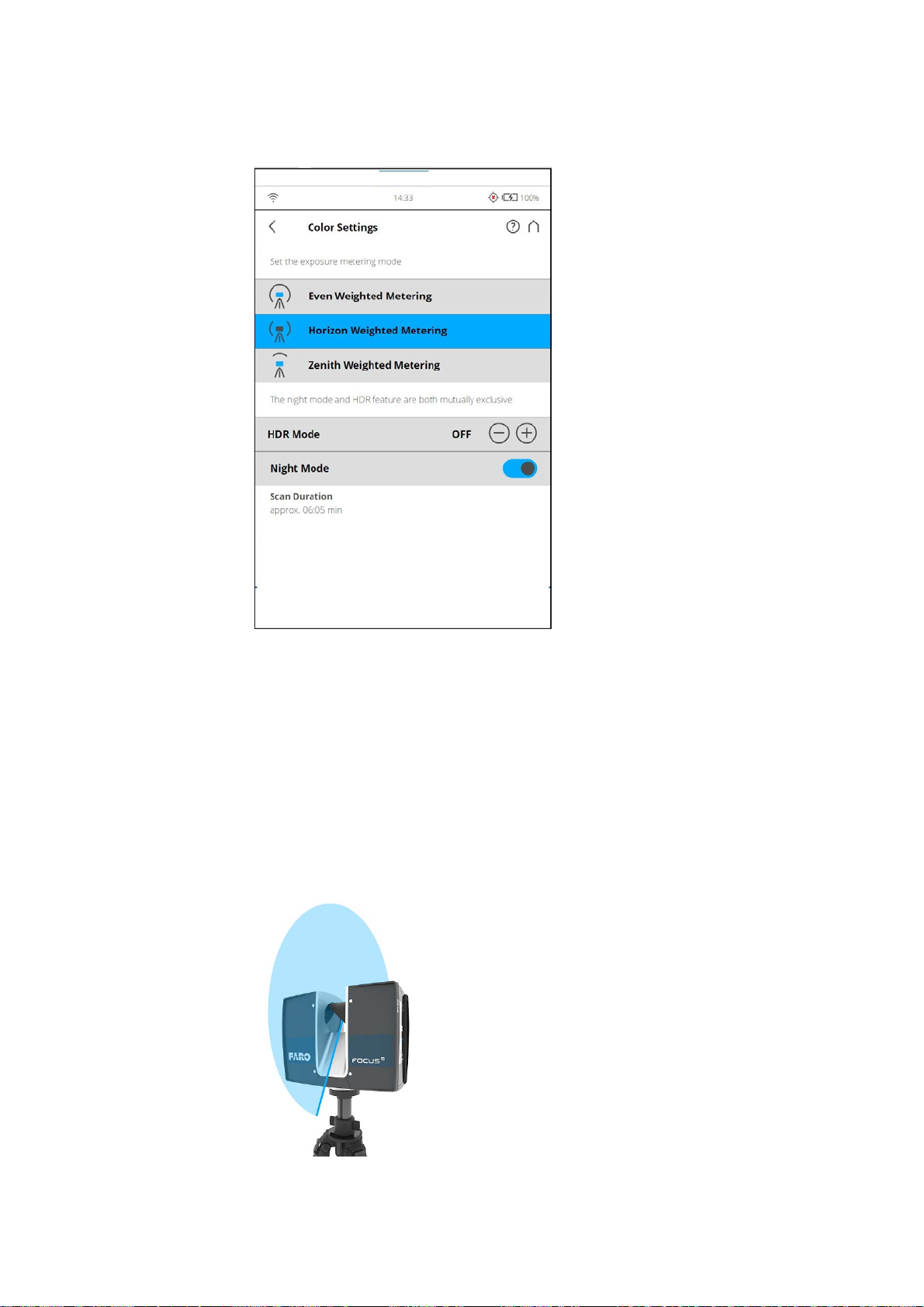
7.3.6 Color Settings
FARO®Laser Scanner Manual
Scan Parameters,
Color Settings
Set the exposure metering mode - Sets the way in which the integrated
color camera determines the exposure for taking the color photos (if colored
scan recording is switched on). Select between three exposure metering
modes to meet the requirements of the current lighting conditions and to get
best possible results for the area of interest.
Even Weighted Metering - To determine the exposure settings, the camera
will use the light information coming from the entire scene and averages
without giving special weighting to a particular area. Use this setting in
scenarios with even lighting conditions.
Figure 7-43: Even weighted metering
64
Chapter 7: Controller Software
Page 70
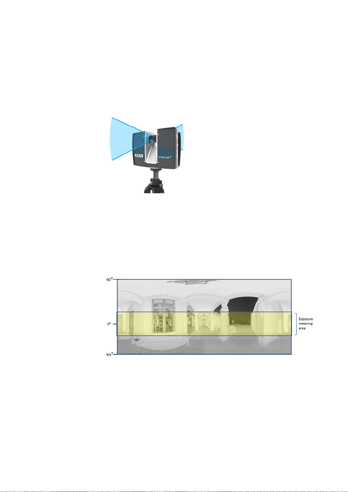
FARO®Laser Scanner Manual
Horizon Weighted Metering - With horizon weighted metering mode, the
camera will use the light information coming from the horizon to determine its
exposure setting. This mode is commonly used in scenarios with bright light
coming from directly above (e.g., indoors with bright ceiling lighting or
outdoors with bright sunlight coming from directly above) and if you want to
achieve the most correct balance of light and exposure for objects at the
horizon. This mode is the default setting. Compared to even weighted
metering, this mode will increase scan duration by approximately 14 seconds.
Figure 7-44: Horizon weighted metering
If the vertical scan area is limited, then the area used to determine the
exposure (i.e., the exposure metering area) might move away from the
horizon. This is the case if the vertical start angle is set to a value > -30° or if
the vertical end angle is set to a value < 30°. The exposure metering area will
then be moved up or down and set to the center of the remaining vertical scan
area. The following figures illustrate this behavior.
Figure 7-45: Exposure metering area (highlighted yellow) for the full vertical
scan area
Chapter 7: Controller Software
65
Page 71
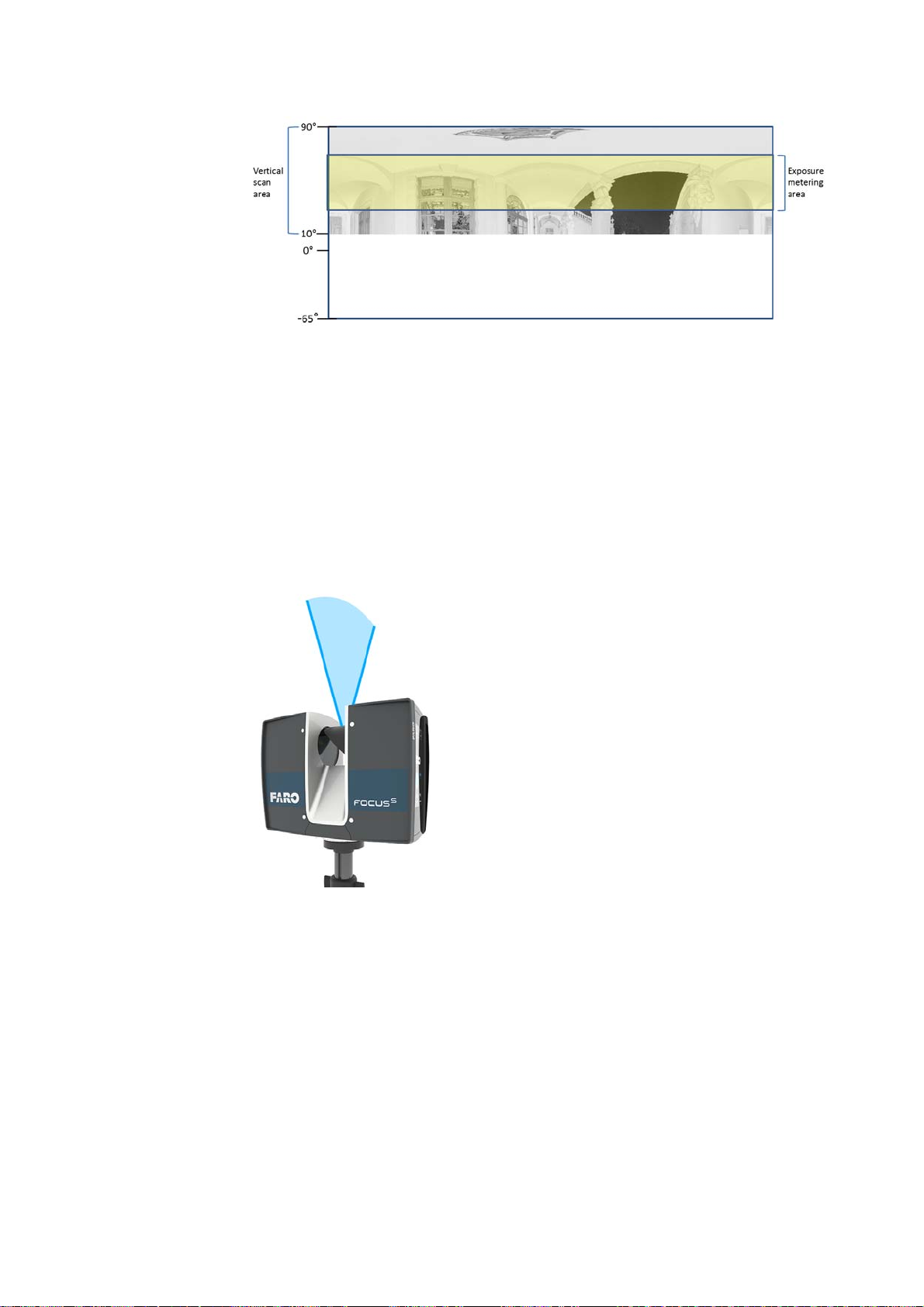
FARO®Laser Scanner Manual
Figure 7-46: Exposure metering area for a limited vertical scan area set to e.g.
10° to 90°
Zenith Weighted Metering - With zenith weighted metering, the camera will
use the light information coming from above the scanner to determine its
exposure setting. Use this mode if there is very bright light coming from
windows or other sources, and if you want to achieve the most correct balance
of light and exposure for objects at the ceiling of building (e.g., for ceiling
paintings in historical buildings). Compared to even weighted metering, this
mode will increase scan duration by approximately 14 seconds.
Scanning with HDR
capturing
Figure 7-47: Zenith weighted metering
HDR Mode
The High Dynamic Range (HDR) imaging method merges images captured
with different exposure settings to one image with a greater dynamic range of
luminosity.
Set the HDR capturing by tapping the + or - button from 2x to 5x. This setting
corresponds to the exposure levels. Typically, settings from 2x, 3x or 5x are
sufficient for most applications. Choose OFF to disable HDR.
66
Chapter 7: Controller Software
Page 72
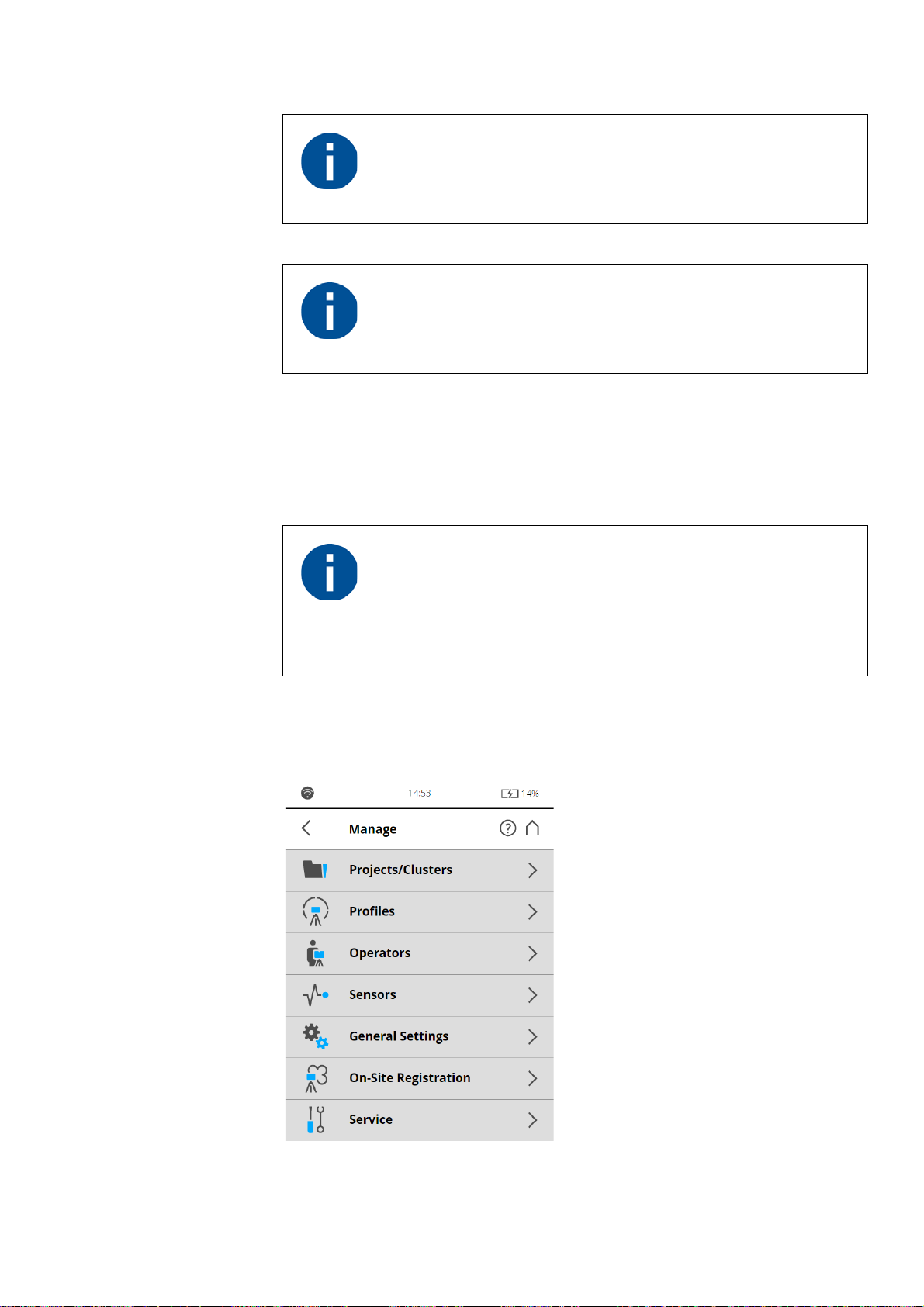
FARO®Laser Scanner Manual
When HDR is enabled, the larger number of captured images
will result in a longer capturing time. The processing time will
be longer in SCENE.
The HDR Mode and Night Mode are both mutually exclusive.
Enabling HDR mode will switch off night mode and enabling
night mode will switch off the HDR mode.
Night Mode
Select the night mode to improve the quality of the color photos in relatively
dark lighting conditions. The image noise will be reduced in low light
situations. However, enabling the night mode will increase the scan duration
significantly if the Scan with Color option is switched on.
7.4 Manage
The best scanning results can be achieved if Night Mode is
enabled along with Horizon Weighted Metering or Zenith
Weighted Metering.
However, very dark lighting conditions may lead to a poor
picture quality even if night mode is activated. This can lead to
grainy images and other artifacts.
Chapter 7: Controller Software
Figure 7-48: Manage
67
Page 73

FARO®Laser Scanner Manual
Projects/Clusters Select the current scan project, add new or edit existing projects. Tap to get a
list of all available projects.
See
Scan Projects and Clusters on page 68 for additional information
Profiles Select the current scan profile, create new or edit existing scan profiles.
See
Scan Profiles on page 75.
Operators Select the current scanner operator, create new or edit existing operators.
See
Factory Settings of HDR, Night Mode and Far Distances on page 78.
Sensors See
Sensors on page 81.
General Settings Opens the menu of the general scanner settings.
See
General Settings on page 88.
On-Site Registration See
On-Site Registration on page 100.
Service Opens the menu for scanner services, like firmware updates, backups or
viewing errors and warnings.
See
On-Site Registration on page 100.
7.4.1 Scan Projects and Clusters
The Projects/Clusters page displays the structure of your real scan projects. A
scan project can consist of a main project that has several sub-projects called
clusters. For example, if you are scanning a multi-level building as a project,
each floor of this building might represent one cluster and each of these floors
or clusters can have further clusters, for rooms.
The structure of the scan project might then be like this:
- Office building
- Floor 1
- Room 1
- Room 2
- Room 3
- Floor 2
- Room 1
- Room 2
68
Chapter 7: Controller Software
Page 74
FARO®Laser Scanner Manual
Before starting with your scan project, you may enter this structure here.You
can reproduce the complete structure of your scan project within the scanner
software; or with SCENE software and transfer the project to the scanner
through the SD card. Please read the SCENE software manual for more
information.
Once the project structure has been created, assign the single scans to the
corresponding clusters. To do this, select a scan project and cluster before
starting a scan. This project should correspond to the current scanner position.
For example, if you take scans in the office building on floor 2, in room 2,
select “room 2” from the project list and then start taking the scans in this
room. The next scans are then assigned to the selected project or sub project
“room 2” until you select another cluster. This information will be attached to
each scan and helps SCENE to automatically combine the scans to scan
clusters and thus to automate the registration of the scans. For more
information on scan registration and combining scans to cluster, see the
SCENE user manual.
You can enter scan projects with the controller software of the scanner or,
more conveniently, with SCENE and then transfer the project to the scanner
through the SD card. Please read the SCENE user manual for more
information on this.
Please note: Every project and cluster gets a unique internal
identification number when it is created. Combining the scans
to scan clusters during post processing in SCENE will be done
according to this identification number and not on the basis of
the project name. This is particularly relevant when working
with several scanners on the same scan project. In this case,
you must create the project structure once as a master and
then transfer it to all of your scanners. Thus, it is not
recommended to create or edit a project of the same scan
project separately on each scanner. Even if the separately
created projects and clusters have the same name, they will get
different identification numbers and will be treated as different
projects by SCENE.
Chapter 7: Controller Software
69
Page 75
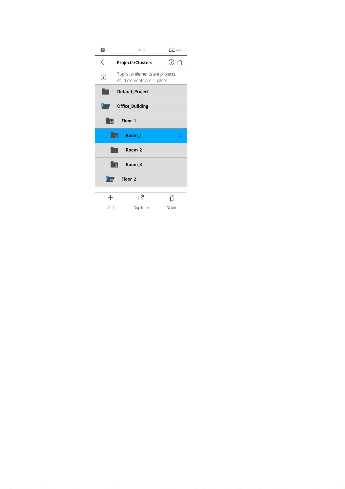
FARO®Laser Scanner Manual
Figure 7-49: Projects List
This view shows a list of all created scan projects/clusters.
The Default_Project is a standard project that can be selected when working
in no particular scan project. The Default_Project is not deletable and you can
not change its name or parent project.
Add a scan project or cluster
To add a project, tap the + button at the bottom of the projects list. A new
subproject called Default_Project
.1 will be added to the selected project. Tap
the field to open its parameters.
70
Chapter 7: Controller Software
Page 76
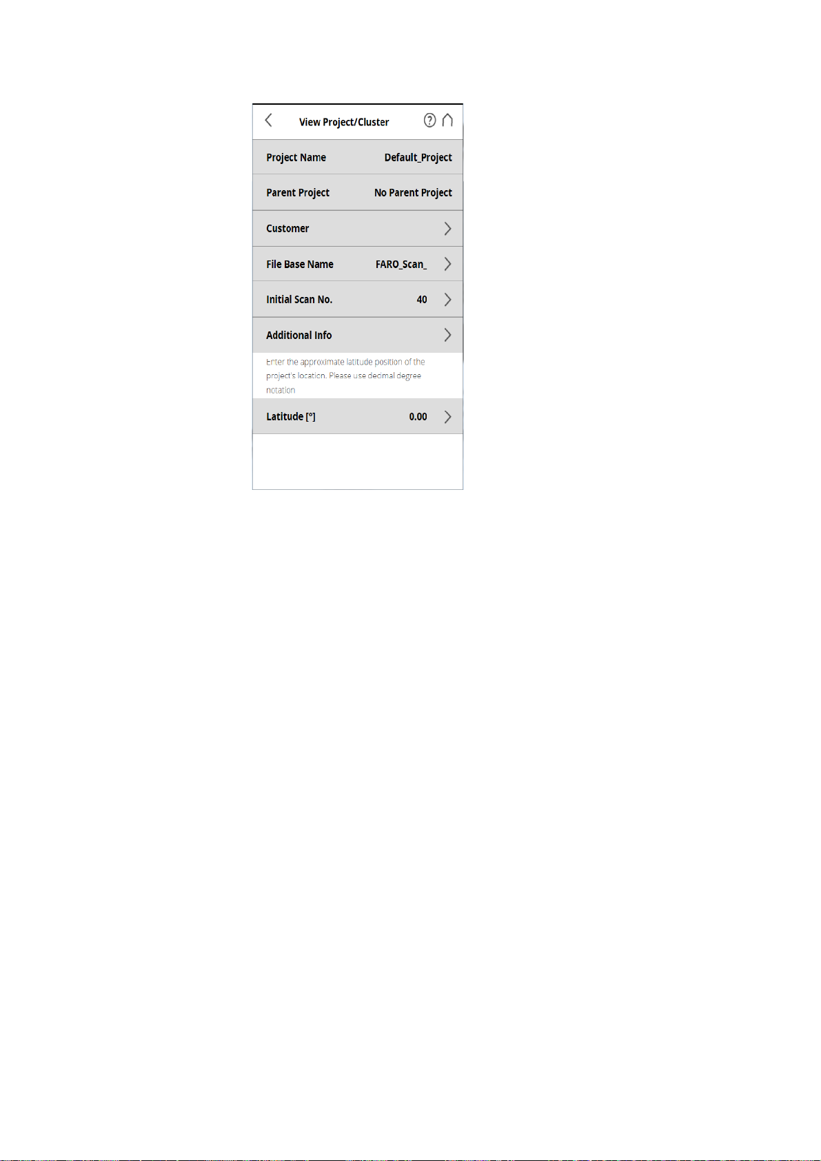
FARO®Laser Scanner Manual
Figure 7-50: View Project
Here, you can change the name and enter further details of the new project. If
you want the new project to be a main project without any parent projects, you
must either change its parent project to No Parent Project, or select the
Default_Project before adding the new project. With the Default_Project,
selected new projects will be added as a main project without parent projects.
Project Name The name of the item. Tap to change the name. A name must start with a letter
and may contain letters, digits, and underscores.
Parent Project The parent project of the displayed item. “No Parent Project” means that the
current item is a project and not a cluster. Tap this button to change the parent
project or parent cluster. A new screen appears with a list of all available
parent projects or parent clusters. Select the parent project/cluster from this
list. The currently edited item will then be assigned as a cluster to this project/
cluster.
Chapter 7: Controller Software
71
Page 77
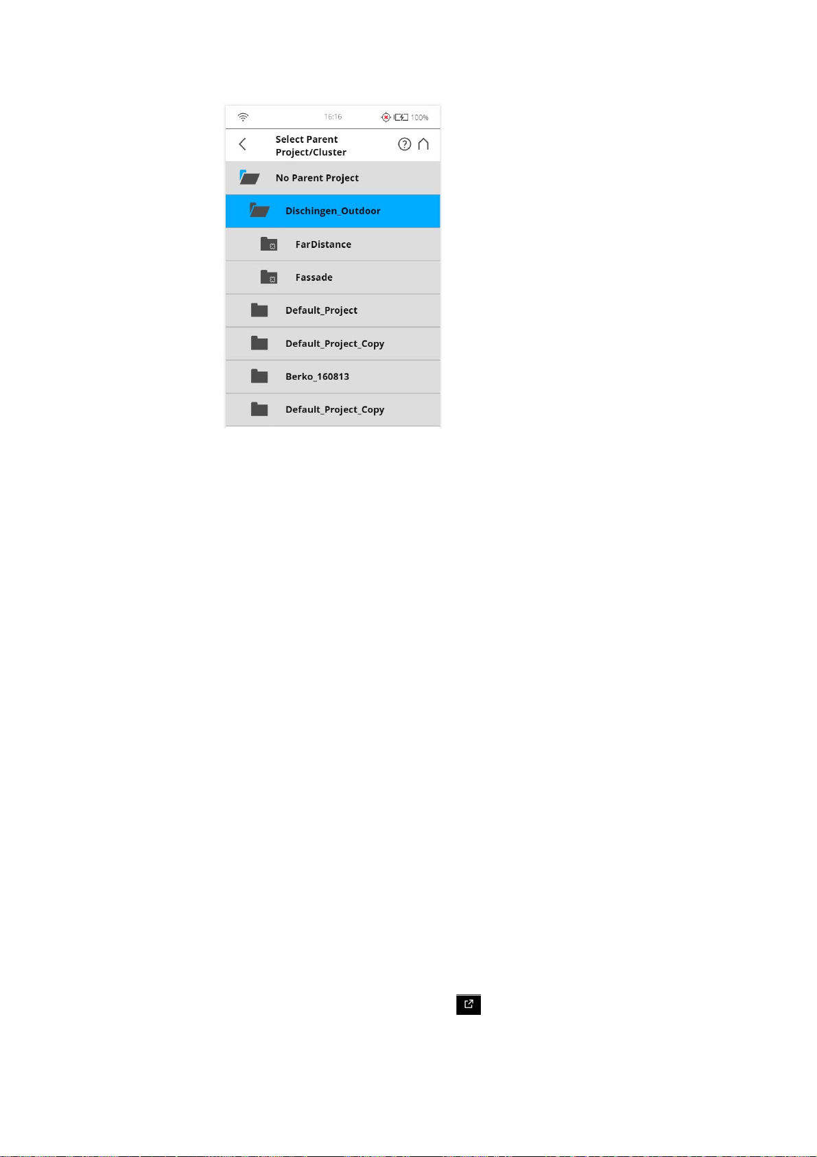
Figure 7-51: Select Parent Project/Cluster
FARO®Laser Scanner Manual
This view shows all available projects and clusters that are applicable to be a
parent project/cluster. Tap on a button to select the parent project/cluster. The
selected parent project/cluster will be highlighted.
No Parent Project Tap this button if the project is supposed to be a project with no parent project.
Project Information
Customer If you are carrying out the scan project for a customer, you can enter that
name here.
File Base Name The scan will be saved with a file name consisting of this base name followed
by the current scan number.
Initial Scan No. Automatically increments with each successive scan. Can be reset and can be
used to indicate the number of scans per scan session.
Additional Info Additional project information.
Latitude [°] Enter the approximate (+/- 10° is sufficient) latitude position of the scan
project. This information helps to improve the accuracy of the inclination
sensor and leads to better scan registration results. Enter the latitude value in
decimal degree notation.
Duplicate a scan project
Instead of adding a completely new project or cluster, you can also create new
projects by duplicating existing ones. For this, select the project that you want
to duplicate and tap the Duplicate button at the bottom of the list. The
newly created project has the same settings and properties as the original
project.
72
Chapter 7: Controller Software
Page 78

FARO®Laser Scanner Manual
To add a cluster, select the parent project or cluster and click the Add button .
A new cluster will be added to the selected project/cluster. If you want the new
cluster to be a main project without any parent projects, you have to change its
parent project to „No parent project“.
A cluster can be moved to represent a new top level project by clicking it,
entering the View Project screen and modifying its Parent Project to No
Parent Project. In the same way, it can be moved to be a cluster of any other
project or cluster.
To select a project/cluster, click its button in the list. The selected project will
be highlighted. To view or change details of the selected project, touch its
button once more.
To display available clusters of a project/cluster, select it and the list will be
expanded with its clusters. Proceed accordingly with further clusters.
Delete a scan project
To delete a project or cluster, select it in the list and tap on the Delete button.
If the project or cluster has subordinates, they will be deleted too.
How scan projects are saved
Scan projects are stored on the SD card. If you remove the SD card from the
scanner, the entire structure of the currently selected project and cluster, as
well as the Default_Project remain on the scanner. All other projects will be
removed from the list, but will be kept on the removed SD card of course. If
you insert a new SD card, the selected project will be saved to the new SD
card as soon as you make changes to it, or as soon as a scan has been
started. If the new SD card already contains projects, it will be added to the
projects list.
Editing a Scan Project
To edit a scan project, select it in the list and tap it once again to reach to its
details view.
Chapter 7: Controller Software
73
Page 79
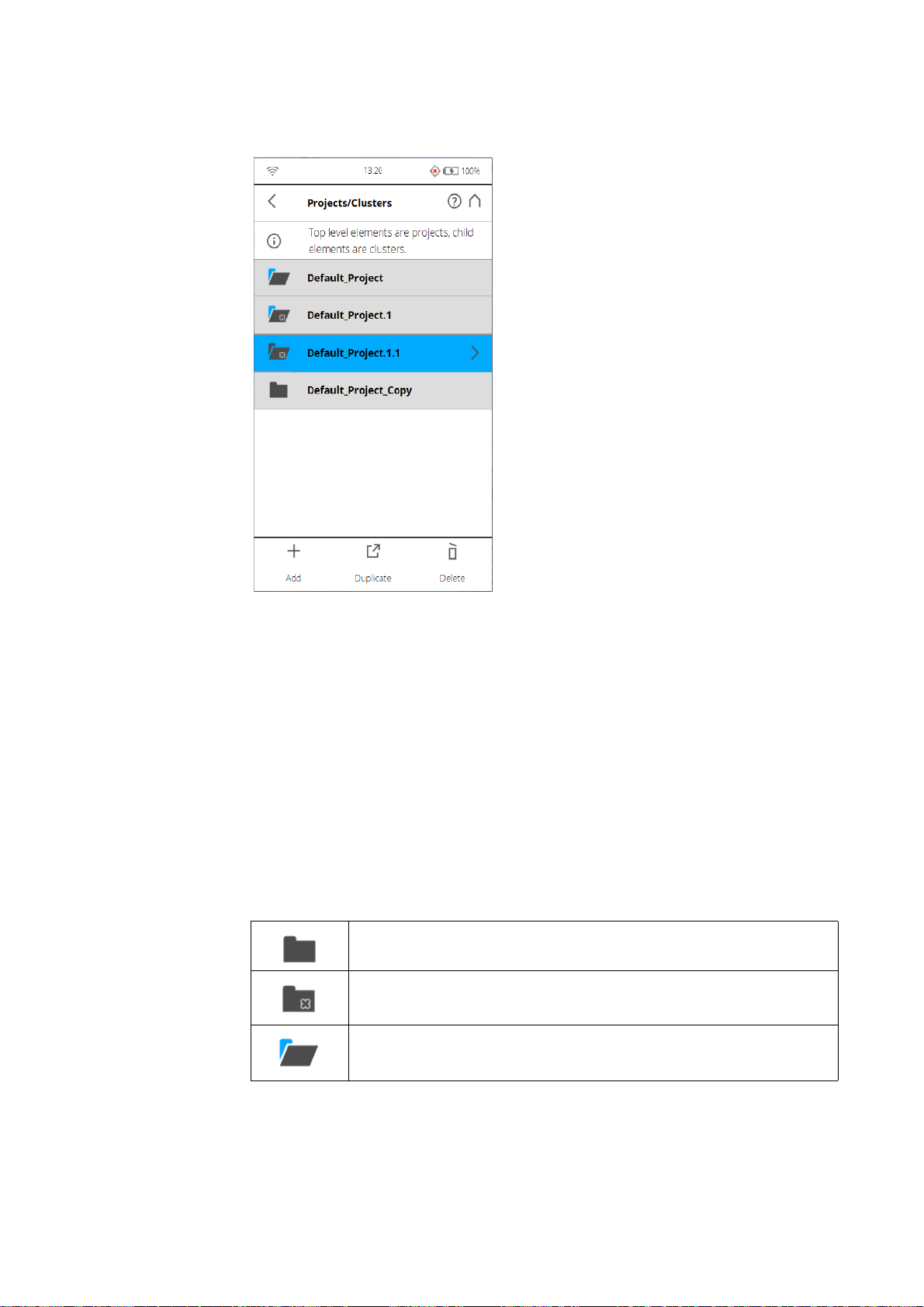
Selecting a Scan Project
FARO®Laser Scanner Manual
Figure 7-52: Project List
The project list contains the currently selected project and all further projects
stored on the SD card.
To select a project, tap its button in the list. The selected project will be
highlighted. To view or change details of the selected project, tap its button
once more.
To display available clusters of a project, select it and the list will be expanded.
Proceed accordingly with further clusters.
If the list of projects exceeds the screen size, scroll the list up or down with the
buttons on the bottom.
Description of the icons on the project buttons:
Project
Cluster
Project has clusters which are currently shown (list is expanded
accordingly)
74
Chapter 7: Controller Software
Page 80
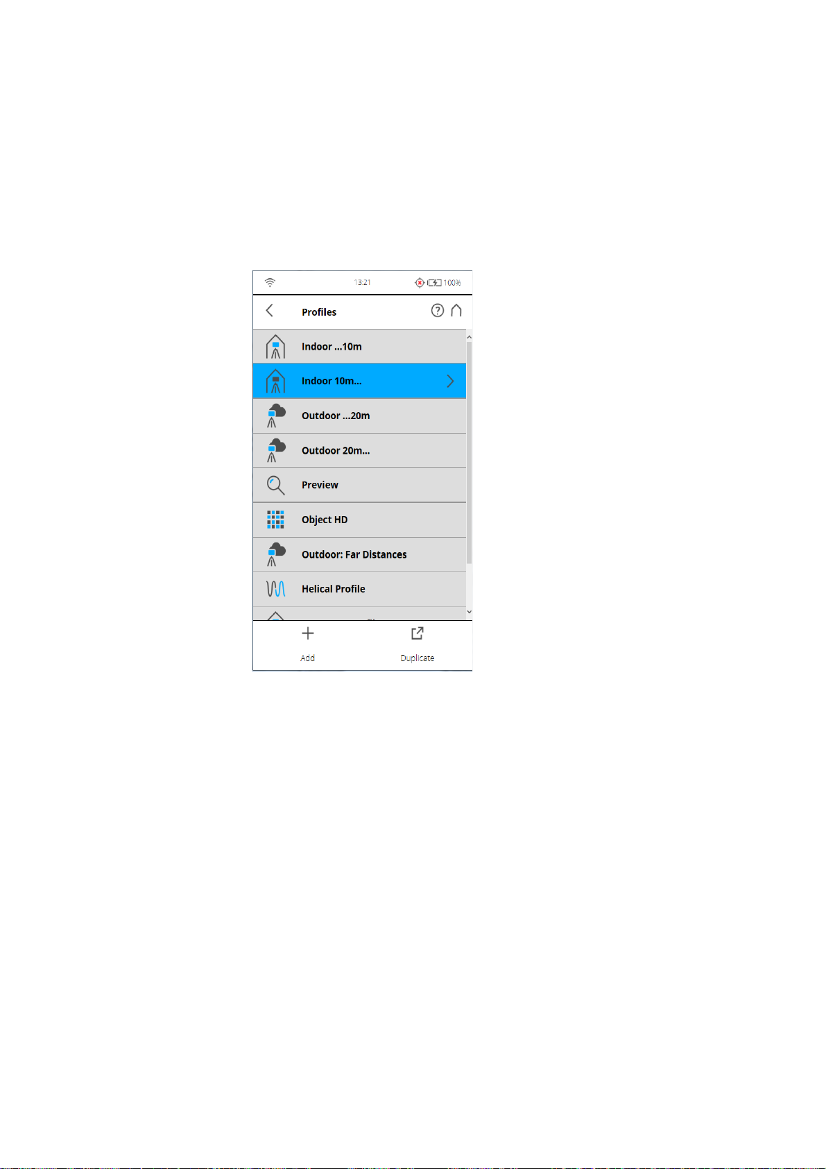
FARO®Laser Scanner Manual
7.4.2 Scan Profiles
Selecting scan profiles to use their parameters for the next scan has already
been described in See
Setting the Scanning Parameters on page 38.. This
chapter will describe how to add new and how to edit existing scan profiles.
The Profiles page displays a context sensitive toolbar at the bottom in order to
add, duplicate, delete, or modify profiles
Figure 7-53: Profiles
As previously mentioned, the FARO Laser Scanner comes with factory
predefined scan profiles (see
Factory Settings on page 108 for an overview of
the available factory predefined scan profiles). These scan profiles are readonly and cannot be changed or deleted. But you can of course add and
manage your own custom scan profiles.
This view shows all scan profiles that are available on the scanner.
To add a new profile, tap the Add button. You can also add new profiles by
duplicating existing profiles. To do this, select the profile that you want to
duplicate and tap the Duplicate button. Tap again on the profile. A new
screen appears to enter the profile name and to adjust its scan parameters.
To delete a custom scan profile, select it and tap the Delete button. You
cannot delete factory predefined profiles.
Chapter 7: Controller Software
75
Page 81
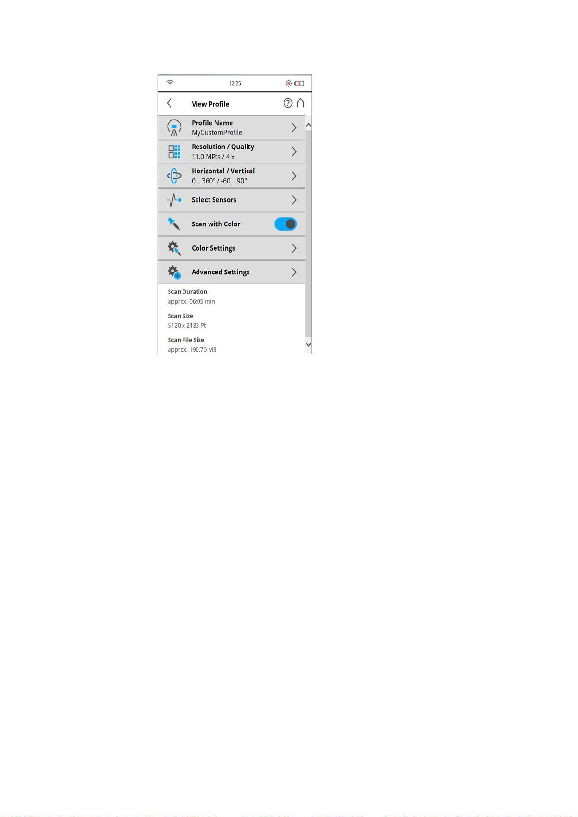
FARO®Laser Scanner Manual
Figure 7-54: Scan Profile Details
Profile Name: name of the scan profile. Tap to change it.
The further settings in this view are similar to the settings of the scanning
parameters. For more information, see
Editing a Scan Profile
Scan parameters on page 59.
To edit a scan profile, select it in the list and tap it again to view its details. You
cannot edit predefined profiles.
To view the details of the selected profile, tap once again.
76
Chapter 7: Controller Software
Page 82
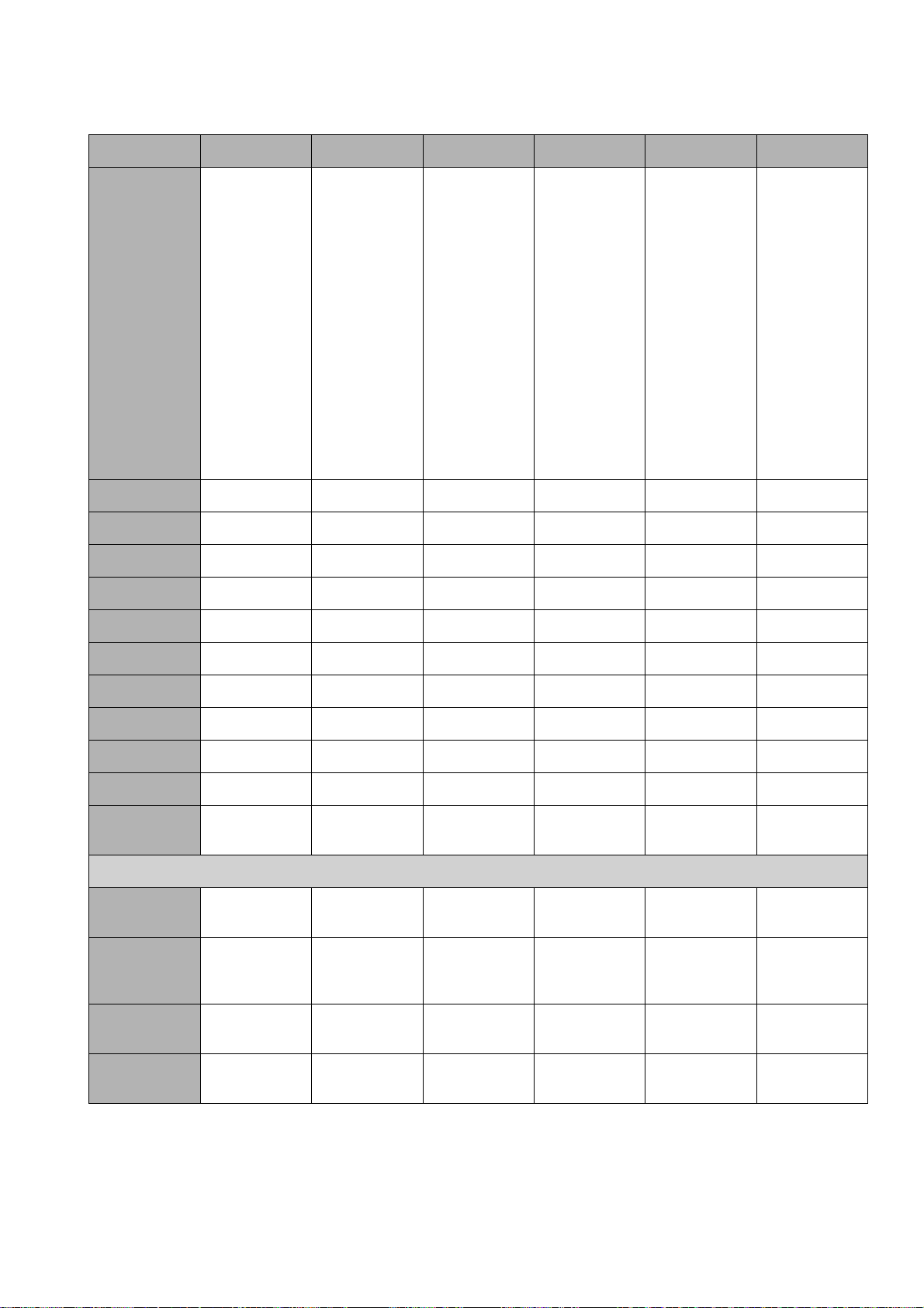
FARO®Laser Scanner Manual
Indoor...10m Indoor 10m... Outdoor...20m Outdoor 20m... Preview Object HD
Factory Predefined Scan Profiles Overview
Description
Quality
Vertical Area
Hor. Area
Inclinometer
Compass
Scan
indoors
where the
distances
from the
scanner to
the main
objects of
interests are
less than
10m
Scan
indoors
where the
distances
from the
scanner to
the main
objects of
interests are
greater than
10m
Scan outdoors where
the distances from
the scanner
to the main
objects of
interests are
less than
20m
Scan outdoors where
the distances from
the scanner
to the main
objects of
interests are
greater than
20m
Capture a
fast and
rough preview scan of
the environment in low
resolution.
Scan certain
objects or
areas in very
high resolution. It is recommended
to limit the
scan area to
the object or
area of interest, else the
scan might
take very
long to complete.
3x 4x 4x 4x 4x 6x
-60° - 90° -60° - 90° -60° - 90° -60° - 90° -60° - 90° -60° - 90°
0° - 360° 0° - 360° 0° - 360° 0° - 360° 0° - 360° 0° - 360°
ON ON ON ON ON ON
ON ON ON ON ON ON
Altimeter
Use GPS
Color
Clear Contour
Clear Sky
Distance
Range
Resolution
(MPts)
Net Scan
Duration
(hh:mm:ss)
Scan File Size
(mb)
Scan Size (Pt)
ON ON ON ON ON ON
OFF OFF ON ON ON ON
ON ON ON ON OFF ON
ON ON ON ON ON ON
ON ON ON ON ON ON
Near Near Normal Far
Normal Near
Distances
The following values refer to full area scans (360° horizontally / 300° vertically):
11 28.2 28.2 44 2.8 176.0
00:05:11 00:08:52 00:08:52 00:09:12 00:01:27 01:58:49
190.70 243.88 243.88 171.18 8.53 2338.20
5156 x 2134 8248 x 3414 8248 x 3414 10310 x
4268
2578 x 1068 20622 x
17066
Chapter 7: Controller Software
77
Page 83
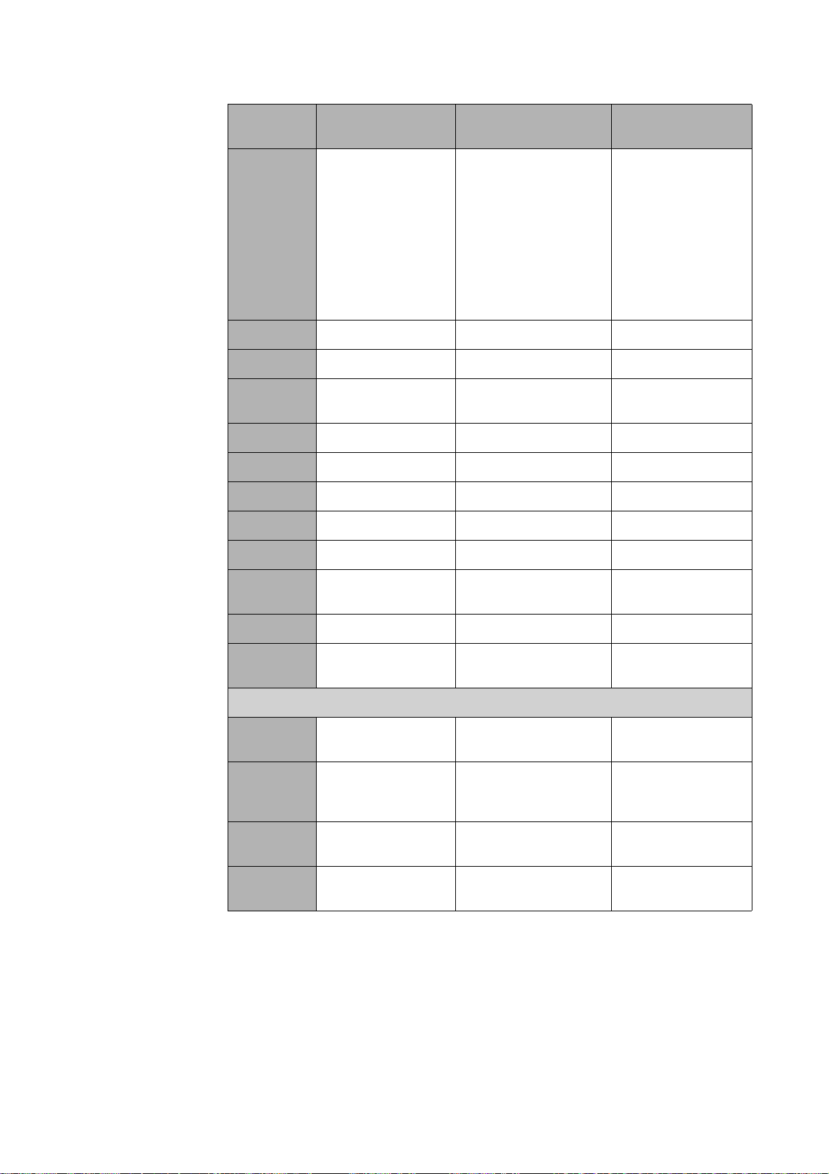
FARO®Laser Scanner Manual
Factory Settings of HDR, Night Mode and Far Distances
Indoor HDR Outdoor HDR
Outdoor: Far
Distances
Description
Quality
Vertical Area
Horizontal
Area
Inclinometer
Compass
Altimeter
Use GPS
Color
Scan indoors
where the distances from the
scanner to the
main objects of
interests are less
Scan indoors where
the distances from
the scanner to the
main objects of interests are more, with
HDR quality.
Scan outdoors
where the distances from the
scanner to the
main objects of
interests are far.
than 20m with
HDR
quality.
4x 4x 4x
-60° - 90° -60°...- 90° -60° - 90°
0° - 360° 0° - 360° 0° - 360°
ON ON ON
ON ON ON
ON ON ON
OFF ON ON
ON ON ON
Clear
Contour
Clear Sky
Distance
Range
The following values refer to full area scans (360° horizontally / 300° vertically):
Resolution
(MPts)
Net Scan
Duration
(hh:mm:ss)
Scan File
Size (mb)
Scan Size
(Pt)
ON ON ON
ON ON ON
Normal Normal Normal
28.2 44 44
00:07.42 00:10:16 00:11:27
243.88 292.95 292.95
8248 x 3414 10310 x 4267 10310 x 4267
78
Chapter 7: Controller Software
Page 84
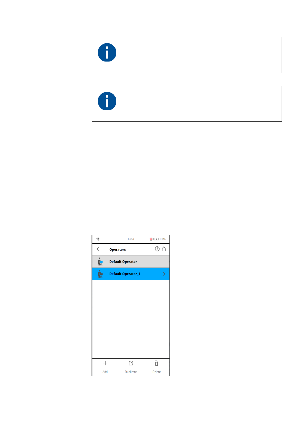
FARO®Laser Scanner Manual
7.4.3 Operators
Please note: Outdoor: Far Distances is not supported on
M
Focus
70 and FocusS 70.
When taking color scans, the Night Mode may significantly
increase the exposure time and lead to a much longer overall
scan time.
Information about which scanner operator has recorded which scans might be
useful for the person who is post-processing the scans; especially when there
are several scanner operators working on the same scan project.
You can assign scanner operators to the captured scans. To do this, select the
operator in the operators list. Create an operator profile first if it does not
already exist. The information about the selected operator is then stored in the
data of the next scans and can be accessed in SCENE during the post
processing of the scans.
Creating an Operator Profile
Chapter 7: Controller Software
Figure 7-55: Operator Profiles list
79
Page 85
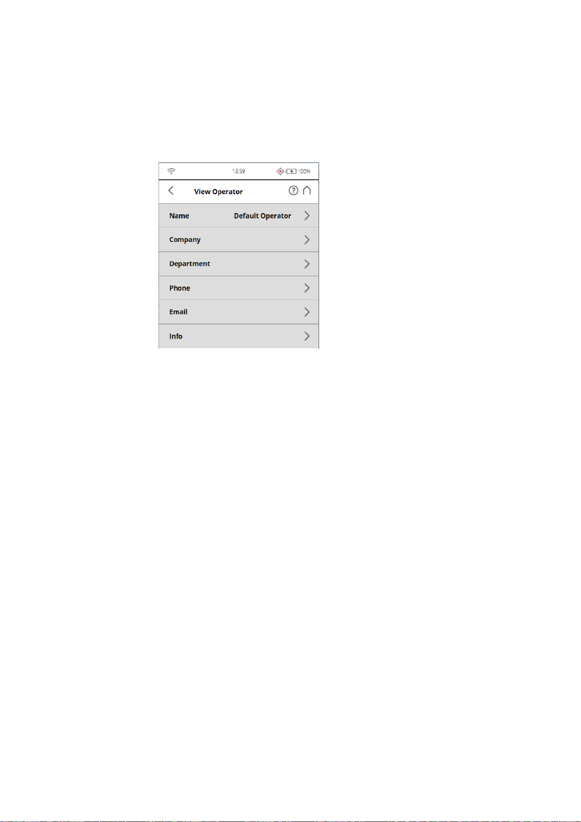
FARO®Laser Scanner Manual
To add a new operator profile, tap the Add button. You can also add new
operator profiles by duplicating an existing operator profile. To do this, select
the operator profile you want to duplicate and tap the Duplicate button. Tap
again to view a screen to enter the operator profile details.
To delete an operator profile, select it and tap the Delete button.
Figure 7-56: Operator Profile details
Name - The name of the scanner operator.
Company - The name of the company providing the scanning service.
Department - The department the operator works for.
Phone - The operator's phone number.
Email - The operator's email address.
Info - Any additional information required by the service provider or shift
leaders, project managers, and so on.
Editing an Operator Profile
To edit an operator profile, select it in the list and tap it once again to find its
details.
Selecting an Operator Profile
Select an operator profile in the list by tapping the corresponding button. The
selected operator profile will be highlighted and assigned to the next captured
scans until another operator profile is selected. To view or edit the details of
the selected operator profile, tap its button once again.
80
Chapter 7: Controller Software
Page 86
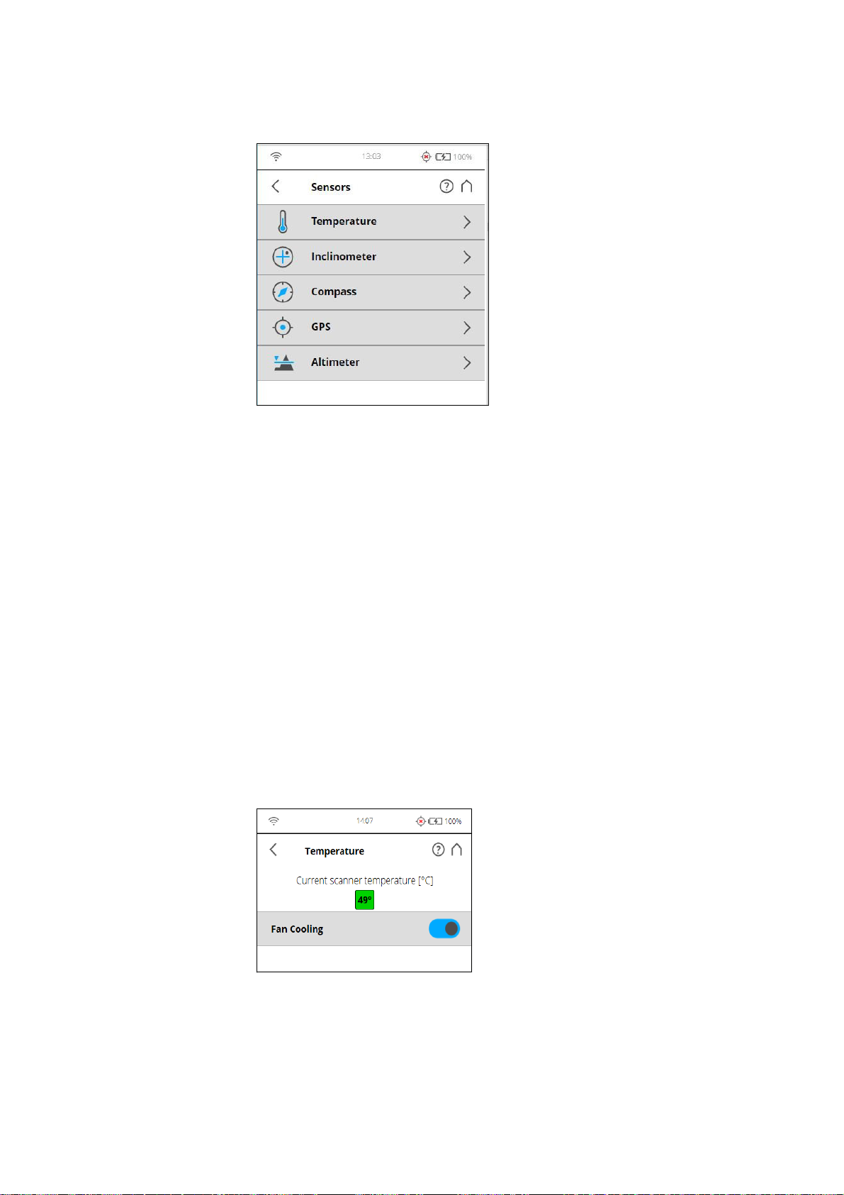
FARO®Laser Scanner Manual
7.4.4 Sensors
Figure 7-57: Sensors
Temperature - Tap to view the current scanner temperature and to switch the
scanner's fan on or off. See
Temperature Sensors on page 81.
Inclinometer - Tap to level the scanner. See
Compensator)
on page 82.
Compass - Tap to view the orientation of the scanner. See
Inclinometer (Dual Axis
Compass on
page 84.
GPS - Tap to view details about the current GPS position and accuracy. See
GPS on page 85.
Altimeter - Tap to view the currently measured altitude of the scanner‘s
position and to sync the altimeter with a reference height. See
Altimeter on
page 86.
Temperature Sensors
Chapter 7: Controller Software
Figure 7-58: Temperature Sensors
The scanner has several temperature sensors integrated that measure the
temperature at different positions inside the scanner. This screen shows the
temperature of the sensor with the currently most critical value.
81
Page 87
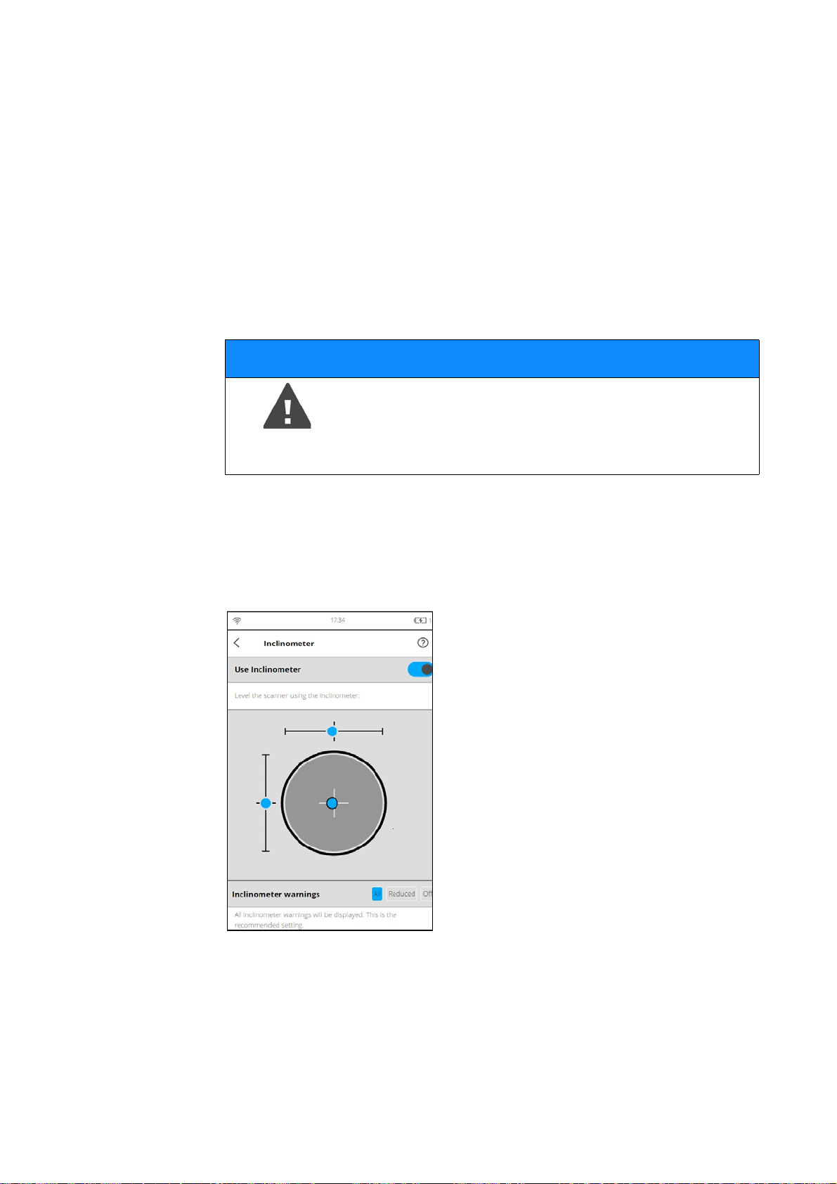
FARO®Laser Scanner Manual
If a sensor is within a critical temperature range, just below or above a critical
value, the indicator will be in the yellow area; scanning will still be possible, but
the temperature might have a negative effect on the scan quality. Therefore, it
is recommended to warm or cool down the scanner until the temperature
indicator is within the green area again.
If the temperature is too high or too low, the indicator will be within the red
area. In that case, scanning will not be possible anymore and the scanner will
shut down within the next minutes.
Fan cooling switches the scanner's integrated fan on or off.
If the temperature is above the critical limit, please check if the fan is switched
NOTICE
Please make sure that the fan is switched off in
exceptional cases only!
If the fan is switched off for a long period of time, the
scanner can overheat and abort scanning or be damaged.
on. If not, please switch it on. The temperature should drop within a short
period of time.
Inclinometer (Dual Axis Compensator)
Figure 7-59: Inclinometer
Level the Scanner using Inclinometer
The view displays a bulls eye bubble level inclinometer as it would appear if
mounted on top of the scanner. If the background color is gray, the
inclinometer is leveled within 2 degrees. The background color of the
82
Chapter 7: Controller Software
Page 88
FARO®Laser Scanner Manual
inclinometer turns yellow, if the scanner is tilted more than 2°. In this case the
accuracy of the inclination measurement is reduced.
If the inclination is larger than 5°, the background color of the level will turn
red. This has two consequences: the inclinometer accuracy will be further
reduced, and the scan quality may be affected.
The two linear levels describe the direction of inclination: If the bubble in the
upper level is on the left side, the scanner is tilted to the right (if you are
standing in front of the display). If the scanner is tilted towards you, the bubble
in the left level is in the upper half.
Inclinometer Warnings
An Inclination Warning icon in the header bar is only visible when the current
inclination of the scanner is above 2° (the icon becomes yellow) or the
icon becomes red if the scanner is tilted more than 5°.
To get reliable measurements from the built-in dual axis compensator you
must set up the scanner with an inclination less than 5° before starting your
next scan. Note that inclinations greater than 2° are measured with less
precision, which can affect the scan registration. To align the scanner you can
use either a bubble inclinometer at the tripod or the inclinometer screen.
The displayed warnings can be configured as follows:
All
An inclinometer warning will be displayed if the scanner is tilted more than 2°.
This is the recommended setting.
Reduced
An inclinometer warning will be displayed if the scanner is tilted more than 5°.
Off
No inclinometer warnings will be displayed in the header bar.
Chapter 7: Controller Software
83
Page 89
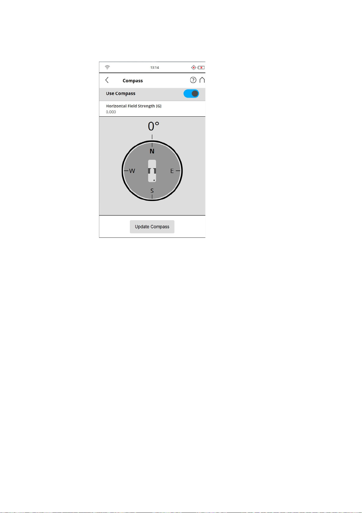
Compass
FARO®Laser Scanner Manual
Figure 7-60: Compass
The built-in electronic compass measures the orientation of the scanner on the
earth‘s surface which is useful information for the registration process.
This information is attached to each scan and can be used for the scan
registration in SCENE (see SCENE user manual for more information).
If you want SCENE to use the compass data for the scan registration, switch
the Use Compass button to ON, otherwise switch it to OFF. This setting
affects the current scanning parameters and has the same function as the
equivalent button in the parameters settings. See
Parameters
on page 38.
Setting the Scanning
You can monitor the current orientation of the scanner on this screen. Initially,
when entering this screen, the orientation is not displayed. To see the current
orientation of the scanner, tap the Update Compass button on the bottom. For
the measurement, the scanner needs to turn horizontally by 360 degrees.
Please ensure that the scanner can move freely and do not move the scanner
during the measurement.
As soon as the scanner has completed the rotation and determined its
orientation, a compass will be displayed as it would appear if mounted on top
of the scanner. This compass illustrates the current scanner orientation.
Additionally, the measured orientation value will be displayed in degrees.
To get updated orientation data, for example, if the scanner has been moved
to another position, you need to tap the Update Compass button again.
84
Chapter 7: Controller Software
Page 90
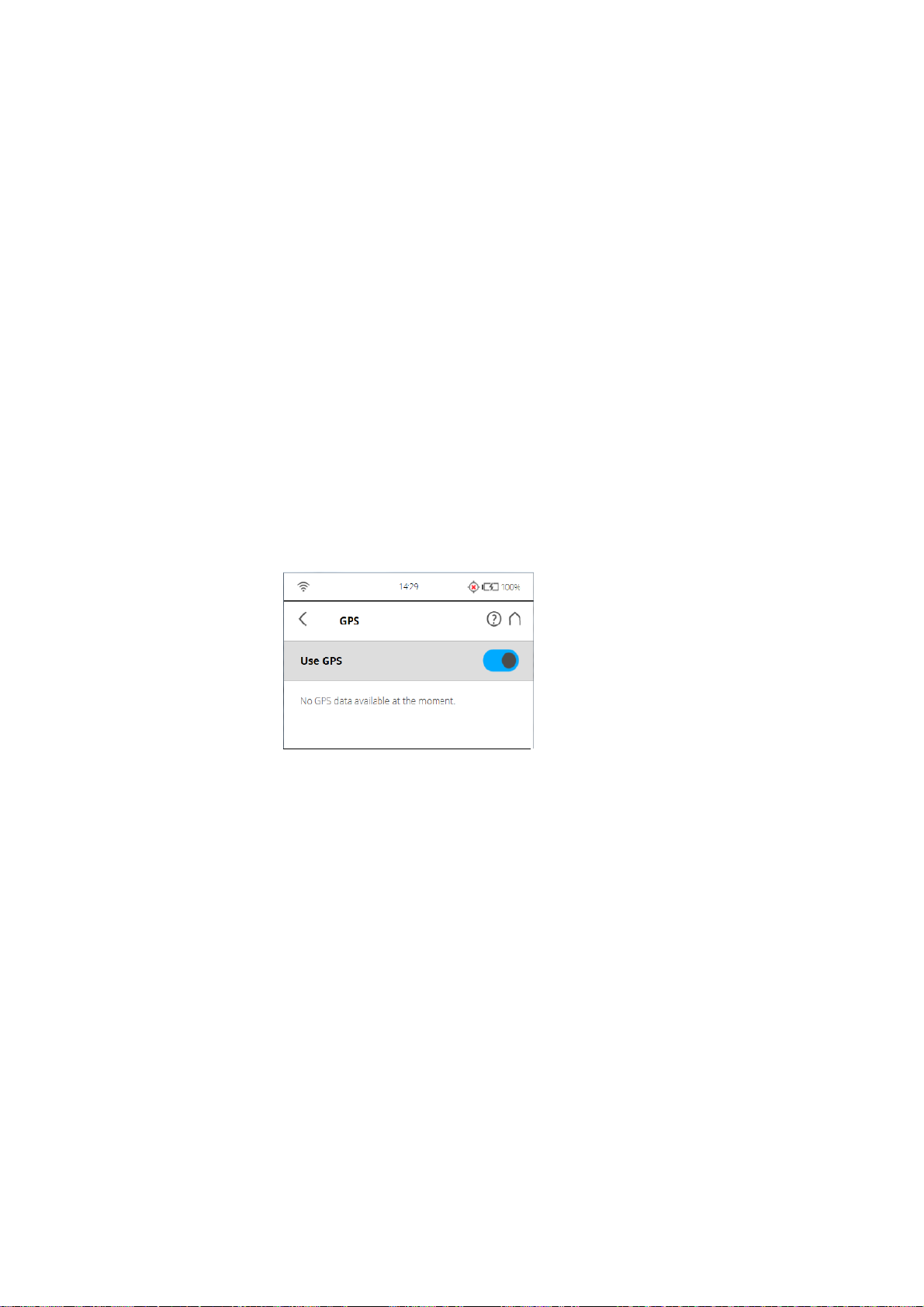
FARO®Laser Scanner Manual
This manual compass measurement only affects the output on this screen and
it is not necessary for the orientation data measured during scanning. During
scanning an orientation measurement is performed automatically.
The accuracy of compass measurements can be affected by magnetic or
other environmental interference. An indicator of the strength of environmental
interference and thus of the current compass measurement accuracy is the
displayed Horizontal field strength of the magnetic field. The typical strength
of the earth's magnetic field depends on geographical position and varies from
0.3 to 0.6 gauss (G). The displayed horizontal field strength is lower than the
absolute field strength because of the inclination of the field. For example, the
typical horizontal field strength for Europe is about 0.2 gauss.
If the measured field strength differs significantly from the expected field
strength, there might be a strong artificial magnetic field near the scanner that
probably affects the measurement. To get the most reliable orientation data for
the scan registration, avoid positioning the scanner near to strong magnetic
fields. If the measured horizontal field still significantly differs, you can switch
the use of the compass data to OFF.
GPS
Figure 7-61: GPS
The position information of the scanner‘s position provided by the built-in GPS
sensor is attached to each scan and is automatically used for the scan
registration in SCENE, if the use of the GPS sensor is switched ON.
Use GPS - Turn the GPS sensor ON or OFF. Unlike the other sensors, GPS
data is only recorded and attached to each scan if this sensor is turned ON.
This function is also available under Scanning Parameters.
Chapter 7: Controller Software
For more information, see
Setting the Scanning Parameters on page 38.
After the GPS sensor is switched ON, it automatically begins searching for
GPS satellites. Note that it can take some minutes to find all the available
satellites and to determine a precise position information. It is recommended
to switch the GPS sensor OFF if it is not needed or if a GPS signal is not
available (for example, if you are scanning indoor).
GPS information - Provides information about the currently measured GPS
coordinates latitude, longitude and the altitude as well as the UTC time of the
last satellite contact and the number of satellites that are currently in view. The
GPS receiver needs the signal of at least three satellites to calculate a 2D
85
Page 91
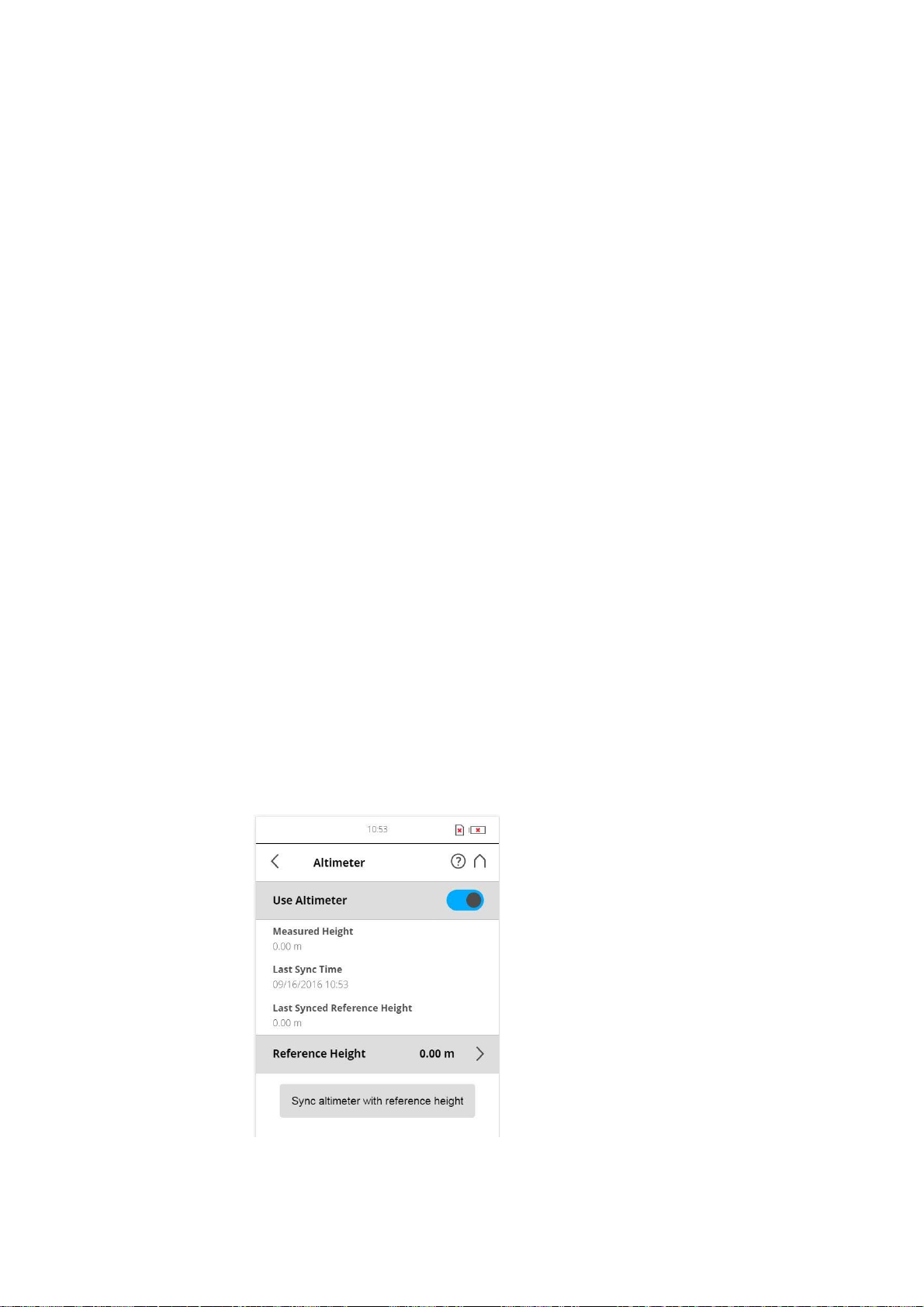
FARO®Laser Scanner Manual
position (latitude and longitude). With four or more satellites in view, the
receiver can determine the scanner‘s 3D position (latitude, longitude and
altitude).
The signal strength bars below the GPS information appear for each satellite
in view with the appropriate satellite number underneath. They indicate the
signal strength for each satellite.
GPS precision - Provides information about the precision of the currently
measured coordinates in meters or feet. The DOP (dilution of precision)
values are an indicator of the quality of the geometry of the current satellite
constellation. In general, good position measurements can be achieved, when
the satellites are located at wide angles relative to each other. In this case the
DOP values are low. Higher DOP values indicate a poor satellite geometry
which might have a negative effect on the position accuracy.
The current GPS status and signal quality is indicated by different GPS icons
in the status bar of the operating software.
Before starting a scan, you should always look at the GPS icon and the
indicated quality. If no GPS data is available or position deviation is high, try to
find a position with better signal quality.
A limited GPS signal can have many different causes. As with portable
navigation devices, make sure that the scanner always has an unobstructed
view of the sky. Obstructions can block the signal reception, causing position
inaccuracy or no position data. The GPS signal can also be reflected by
objects (for example, buildings or mountains), causing the measured position
to wander. The more satellites the sensor has in view, the better the fix is.
Altimeter
(Manage > Sensors > Altimeter)
Figure 7-62: Altimeter
86
Chapter 7: Controller Software
Page 92

FARO®Laser Scanner Manual
The barometric height sensor (altimeter) determines the altitude of the current
scanner position. The altitude determination is based on the measurement of
the atmospheric pressure. The measured altitude is attached to each scan
and can be used for the scan registration in SCENE (see SCENE user manual
for more information). If you want SCENE to automatically use the measured
altitude for the scan registration, switch the Use Altimeter button to ON, else
switch it to OFF. This setting affects the current scanning parameters and has
the same function as the equivalent button in the parameters settings.
For more information, see
Setting the Scanning Parameters on page 38.
To see the currently measured altitude on this screen, the use of the altimeter
must be switched ON.
For scan registration it is sufficient to know the difference in altitude of the
various scanner positions. Before starting your scan project, you should pick a
position of your scanning site which you would like to use as the reference for
the altitude measurements. Move the scanner to this reference position, enter
any height you would like to use for this position and reset the altimeter to this
reference height by taping on the Sync Reference Height button. All further
altimeter measurements will then be done on the basis of this reference
height.
If you want comparable height measurements across different projects, you
can sync the altimeter with a real altitude. For this, pick a reference position of
your scanning site where you know the approximate altitude above sea level.
You can get this value from GPS, a topographic map, or from Google Earth.
As the altimeter determines the altitude based on the measurement of the
atmospheric pressure, changes in the air pressure caused by changing
weather conditions have an effect on the resulting altitude. To have precise
altitude measurements, you should therefore check the reference altitude from
time to time, at least at the beginning of each project day or if you experience
changes in the weather. To do this, move the scanner to your reference
position again and compare the altitude reading with the reference height. If
there is a difference, sync the altimeter with the reference height again.
Chapter 7: Controller Software
87
Page 93
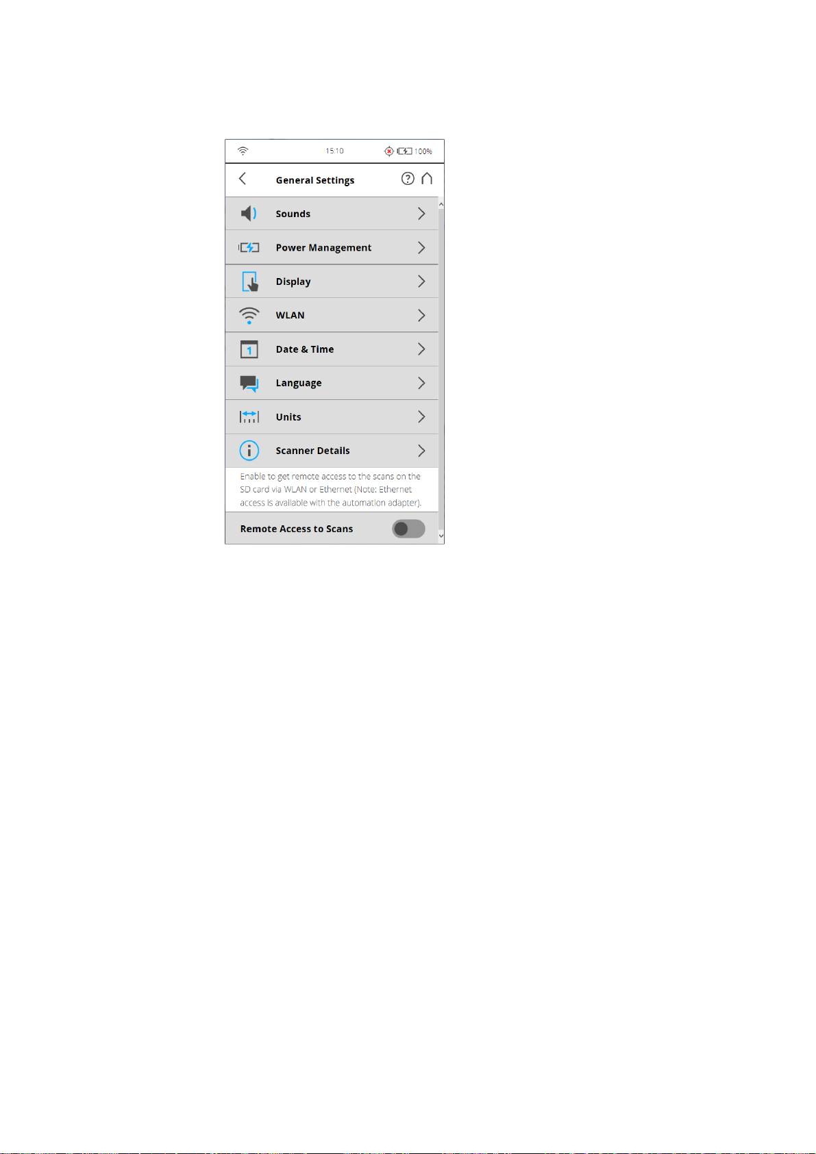
7.4.5 General Settings
FARO®Laser Scanner Manual
Figure 7-63: General Settings
Sounds - Change the volume of the scanner sounds, enable or disable
scanner sounds.
See
Sounds on page 89.
Power Management - View detailed settings regarding the administration of
power like the battery charge level; enable or disable start on power; modify
display settings to optimize power usage.
See
Power Management on page 90.
Display - Set the brightness of the screen or change the theme of the Home
screen to Dark or Bright.
See
Display on page 91.
Date & Time - Change the displayed time and date format and change the
date and time of the scanner.
See
Setting the Date and Time on page 35.
Language - Change the language of the controller software.
See
Setting the Interface Language on page 33.
Units - Change the displayed unit of lengths.
88
Chapter 7: Controller Software
Page 94
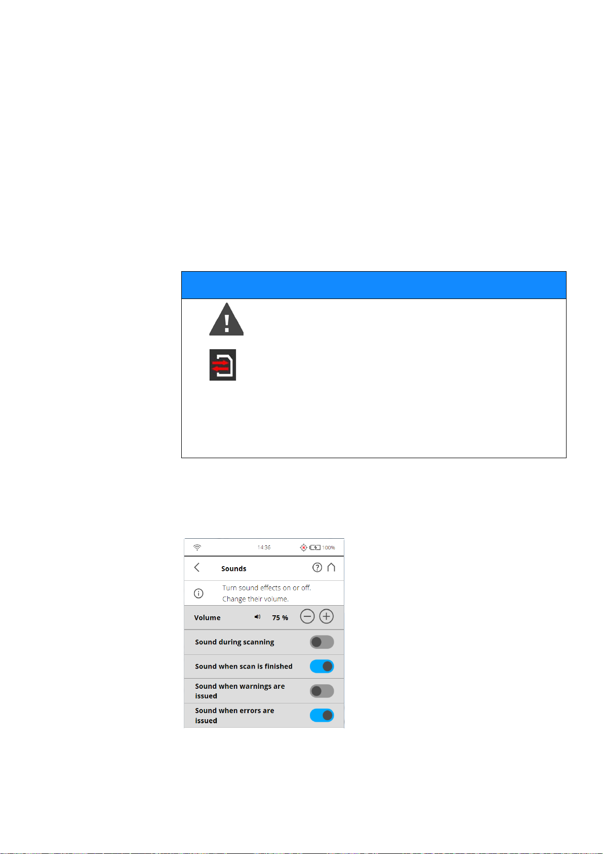
FARO®Laser Scanner Manual
See Setting the Unit of Length and the Temperature Scale on page 37. -
WLAN - The scanner has an integrated antenna that allows to remotely
connect to the scanner with portable devices, like notebooks, PDAs or tablet
computers.
Scanner Details - View and change details of the scanner.
See
Scanner Details on page 99.
Remote Access to Scans - Enabling this function will allow you to have
access to the scans on the inserted SD card on remote devices that are
connected to the scanner through WLAN or Ethernet.
For more information, see
WLAN on page 91.
NOTICE
Risk of data loss!
• Please only use if you’re about to access scan files
through network. Absolutely make sure not to remove
the SD card until remote access is disabled again.
• The status of the SD card will be set to busy as long as
this function is enabled. Please disable it before you
remove the SD card from the scanner. Remote access
will automatically be disabled when shutting down the
scanner, you will have to enable it again after reboot.
Sounds The scanner has a built-in speaker. The scanner signals certain events with
various sounds. You can change the speaker volume here and switch the
sound effects ON or OFF.
Chapter 7: Controller Software
Figure 7-64: General Settings, Sounds
Volume - Increase or decrease the volume of the scanner sounds.
89
Page 95
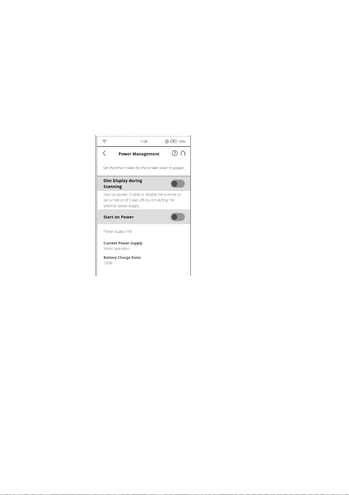
Power Management
FARO®Laser Scanner Manual
Sound during scanning - If switched on, the scanner will give a warning
signal when laser is switched on and scanning starts.
Sound when scan is finished - If switched on, the scanner will inform about
scan completion with a sound.
Sounds when warnings are issued - If switched on, the scanner produces a
warning sound when a warning is issued.
Sounds when errors are issued - If switched on, the scanner produces a
sound when an error is issued.
Figure 7-65: General Settings, Power Management
Screensaver - If the screen has not been touched for a certain period of time,
a screensaver appears on the screen. Change the length of time before the
screensaver appears by tapping the plus or minus buttons. Deactivate the
screensaver by setting the time to „never“. When the screensaver is visible,
simply tap the screen to return into operation mode.
Dim display during scanning - If switched on, the brightness of the screen
will be decreased during scanning to save battery power. Switching this option
to ON is particularly useful for long scans.
Start on Power - Enable the scanner to be turned on (if it was turned off) by
connecting it to the external power supply. This option is useful, for example,
for automation applications.
Power supply info - Informs about the current power supply and the exact
charge state of the battery.
Remaining Battery Life - Gives an approximation of how much remaining
battery life you can actually expect until the battery is empty and needs to be
recharged. The remaining battery life is only available if the scanner is
powered by the battery.
90
Chapter 7: Controller Software
Page 96
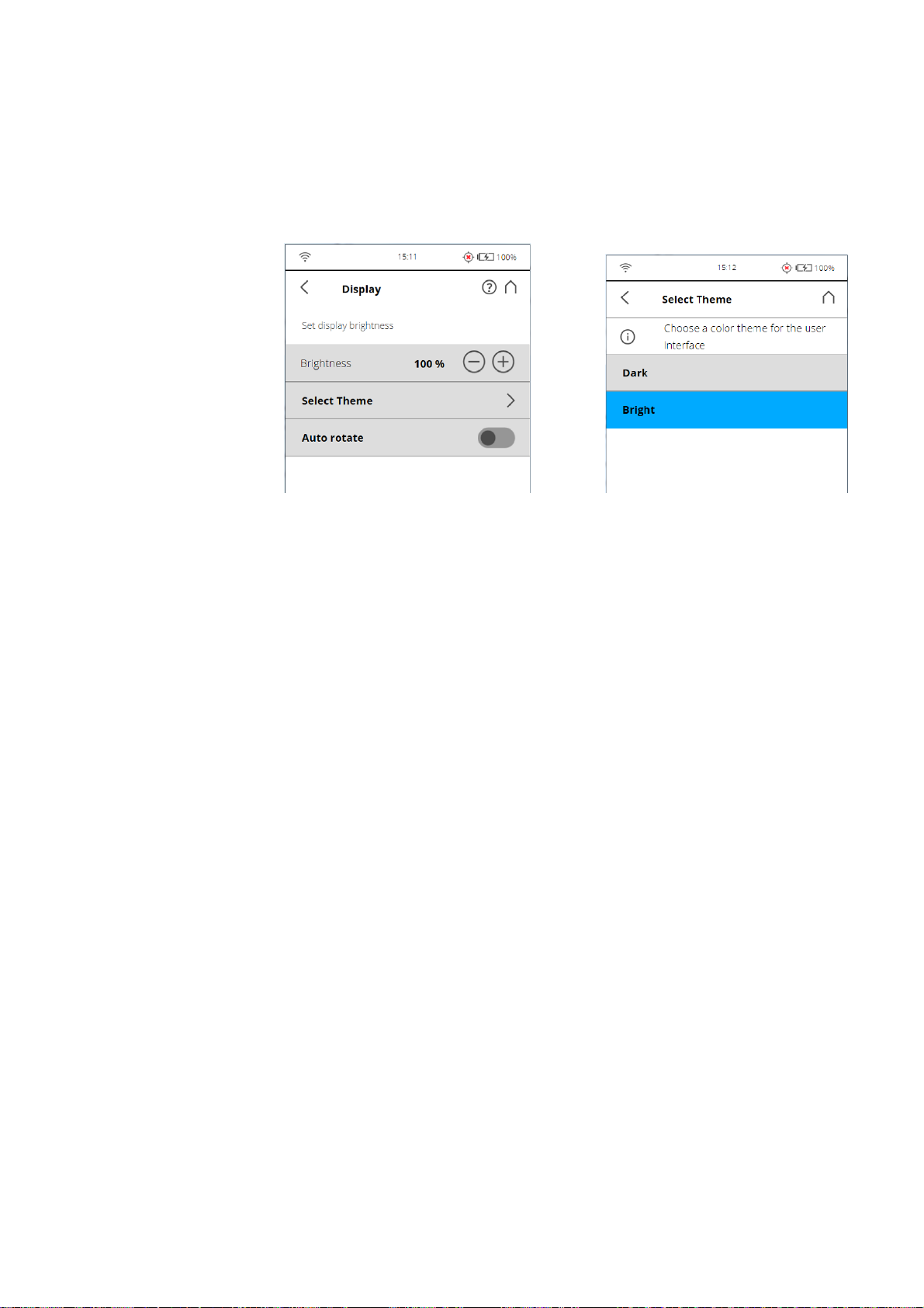
FARO®Laser Scanner Manual
Display
Battery health information - Provides information on the condition of the
currently inserted battery. It informs about the amount of capacity remaining in
the battery. Over time, the capacity of a Lithium Ion battery will decay. If the
indicated battery condition is „Replace Battery“, the remaining capacity of the
battery is very low and you should consider replacing it by a new one.
Figure 7-66: General Settings, Display
Brightness - Set the brightness of the screen.
Select Theme - Change the theme of the Home screen. Tap to get the screen
background theme options to Dark or Bright.
Calibrate the display - If you experience the touch screen to be slightly
misaligned, you can recalibrate it. Tap this button and follow the instructions
on the screen that appears. We recommend using a stylus to calibrate the
display. If the calibration of the touch screen is corrupted you must reset the
calibration of the display to its factory settings.
• Shut down the scanner using the Power button.
• Wait until the scanner has shut down, then press and hold down the Power
button for at least five seconds until the LED on the sensor side of the
scanner illuminates yellow, then release the button again. The scanner will
then boot up and reset the calibration of the touch screen to its factory
settings.
Auto rotate - Turn on to let the display rotate depending on the scanner
orientation. This option is helpful when the scanner is located upside down.
Date and Time See
Language See
Units See
Setting the Date and Time on page 35.
Setting the Interface Language on page 33.
Setting the Unit of Length and the Temperature Scale on page 37.
WLAN The WLAN interface can be used for remote connections, especially if your
scanner is not equipped with an automation interface connection.
91
Chapter 7: Controller Software
Page 97
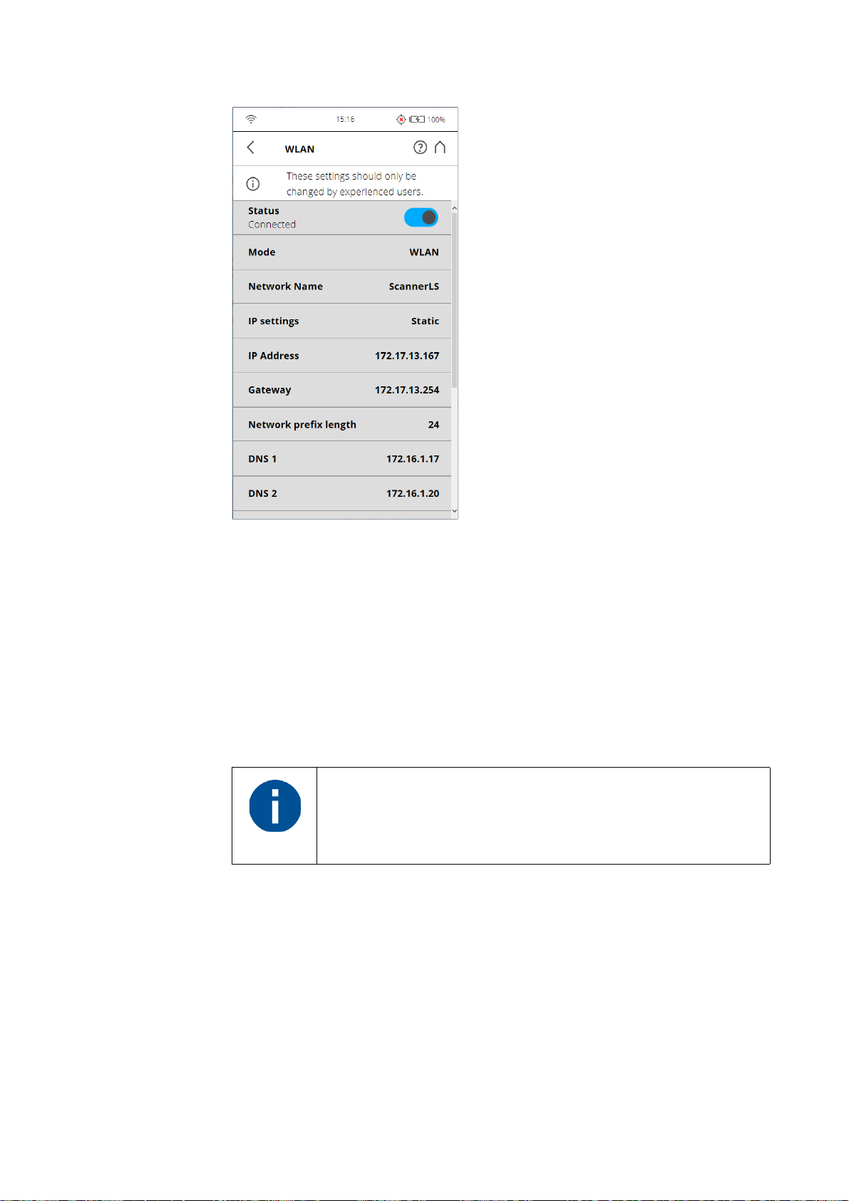
FARO®Laser Scanner Manual
Figure 7-67: WLAN Settings
The scanner has an integrated WLAN module that allows you to remotely
connect to the scanner with portable devices, such as notebooks, PDAs or
tablet computers. Connect your remote device to the scanner through WLAN,
and remotely access the scanner user interface with a standard web browser.
The WLAN option also provides remote access to the scan files on the
scanner SD memory card.
It is possible to turn WLAN off from a remote interface. Since this might
disable the connection to the remote interface, a warning is displayed.
WLAN settings can only be modified on the scanner user
interface, and not with the remote interface.
Changes to the WLAN settings are only possible if WLAN is
turned off.
Status
Tap this button to turn ON or OFF. Indicates whether WLAN is available or not
available. If WLAN is not needed, it is recommended to turn it off.
Note that changes to the WLAN settings are only possible if WLAN is turned
off.
Two different WLAN operating modes are possible:
92
Chapter 7: Controller Software
Page 98
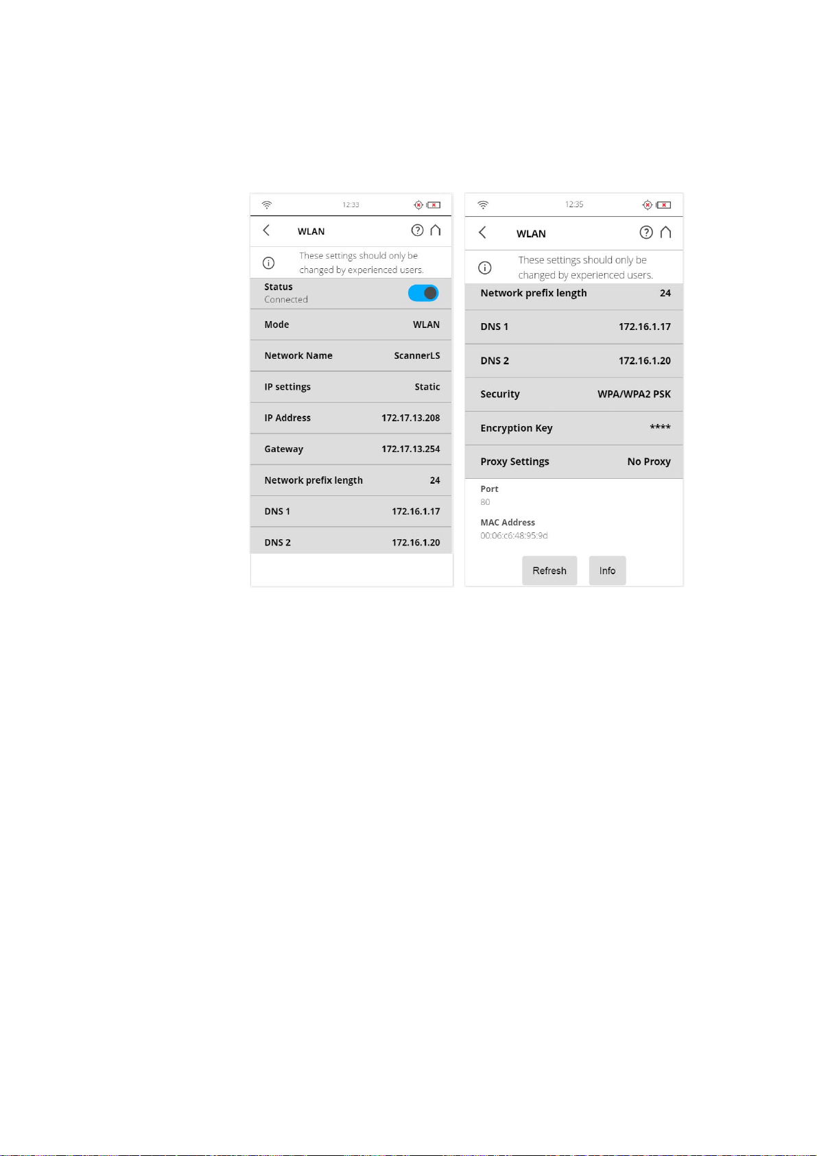
FARO®Laser Scanner Manual
WLAN Mode
Scanner Settings
• WLAN: This setting is also known as infrastructure mode. The network is
configured such that the scanner can connect to an external access point.
• Access Point: The scanner network is configured as an access point.
Figure 7-68: WLAN Mode
Network Name: The name of the wireless network. Tap it to enter a screen where the available networks are displayed and can be selected.
IP settings: Set a static IP Address or obtain one automatically through
DHCP.
The IP settings determine whether an IP address is assigned by a server
using DHCP or set manually (“Static”):
• DHCP: This is the default/recommended setting.
• Static: The IP address is assigned manually. The following settings have to
be provided.
IP Address
The IP address of the scanner. A unique IP address must be preset on the
WLAN network. If your remote device is connected to the scanner, enter this
address into the address field of your web browser (for example,
Chapter 7: Controller Software
93
Page 99
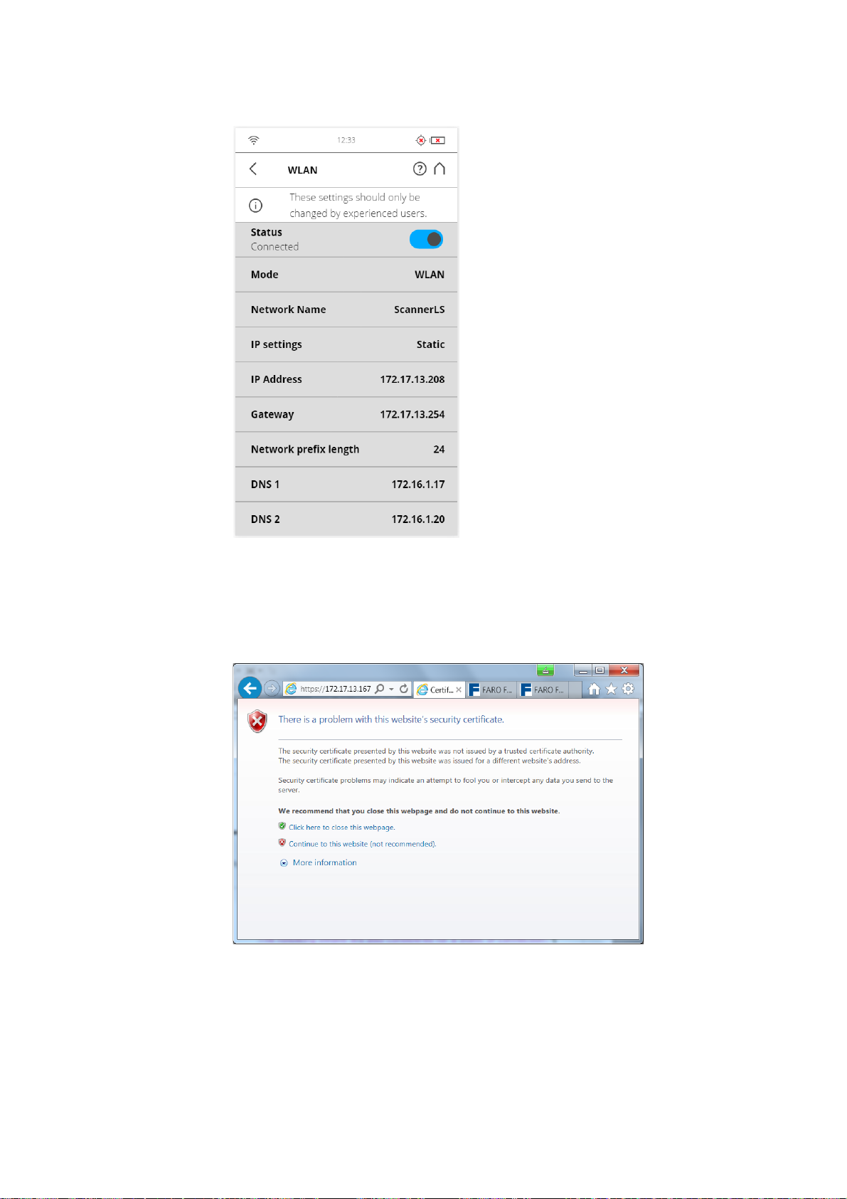
FARO®Laser Scanner Manual
http://172.17.16.23) to access the controller software. Tap to change the
scanner‘s IP address.
Figure 7-69: Connection to Scanner Interface through web browser
If you prefer secured, encrypted communication with the scanner GUI, enable
the secure connection https://172.17.16.23 in the address field of your web
browser. You will receive a security warning from the browser before
connecting to the GUI; confirm to proceed.
Figure 7-70: Scanner secure connection: Warning
Be aware that setting an IP address manually can result in a conflict, if two
devices on the same wireless network claim to have the same IP address.
The following details are also considered for a Static IP connection:
Gateway: The gateway used to access the WLAN network.
94
Chapter 7: Controller Software
Page 100

FARO®Laser Scanner Manual
Network prefix length: The subnet mask used in the WLAN network.
DNS 1: First dynamic name server to use in the WLAN network.
DNS 2: Second dynamic name server to use in the WLAN network.
Security: Choose the security protocol that the access point to which the
scanner will connect uses. The possible options are:
• Open: Connect to an open network that can be accessed by anyone
without a password. The information exchange is not secured.
• WEP: Connect to a network that is secured by WEP. This option requires
an encryption key with 8 to 63 characters. This security level is insecure.
• WPA: First version of the WLAN Protected Access. Not recommended.
• WPA2 PSK: Connect to a network that is secured by WPA2. This option
requires an encryption key with 8 to 63 characters. This is the default/
recommended option.
Encryption key
The scanner network is encrypted with a WPA2 key. Enter this key on your
remote device when prompted to establish the connection to the scanner. If
you want to change the encryption key, tap the button and enter your own key.
The key must consist of 10 to 63 arbitrary digits.
Proxy Settings
Settings related to connection through a proxy.
• No Proxy: Don't use a proxy. Choose this option if the network that the
scanner will connect to has direct Internet access.
• Manual: Use a manually configured proxy. Configuration includes:
• Host: The host name (or IP address) of the proxy server.
• Port: The port through which to connect to the proxy server.
• Exclusion List: A comma-separated list of hosts for which no proxy will
be used.
• User Name: The user name used to log in to the proxy server (if
required).
• Password: The password used to log in to the proxy server (if required).
Chapter 7: Controller Software
Refresh
Tap this button to refresh the WLAN settings displayed in this screen.
95
 Loading...