

Page 1

SECTION 10 -- ENGINE -- CHAPTER 1
SECTION 10 -- ENGINE
Chapter 1 -- Engine
CONTENTS
Section Description Page
Specifications 4..................................................................
Torques 12.....................................................................
Special Tools 14................................................................
Sectional Views 15..............................................................
Troubleshooting 20..............................................................
Overhaul 24....................................................................
10 001 10 Engine 24..................................................................
Removal 24.............................................................
1
Installation 40............................................................
10 001 53 Disassembly 42..........................................................
Engine Assembly on the Bench 56.............................................
Fitting the Bushings 56....................................................
Fitting the Tappets 57.....................................................
Fitting the Camshaft 57...................................................
Fitting the Oil Nozzles 58..................................................
Fitting the Crankshaft 58..................................................
Fitting the Connecting Rod -- Piston Assembly 61.............................
Fitting the Piston Connecting Rod Assemblies in the Cylinder Liners 63..........
BigEndCapAssembly 64.................................................
Fitting the Thermostat Valve 65............................................
Fitting the Cylinder Head 66...............................................
Fitting the Injectors 68....................................................
Fitting the Rocker Arm Assembly 69........................................
Fitting the Timing Gear 69.................................................
Fitting the Injection Pump 72...............................................
Fitting the Additional Counterweights 73.....................................
Fitting the Hydraulic Pump Drive Gear 74....................................
Fitting the Timing Gear Casing 74..........................................
Fitting the Crankshaft Rear Seal 75.........................................
Fitting the Flywheel 75....................................................
Fitting the Oil Pump 76....................................................
Fitting the Oil Sump 77....................................................
Page 2

2
Section Description Page
10 102 70 Crankshaft Front Seal 83.....................................................
SECTION 10 -- ENGINE -- CHAPTER 1
Fitting the Crankshaft Front Seal 77.........................................
Fitting the Crankshaft Front Pulley 77.......................................
Fitting the Cooling System Union 78........................................
Fitting the Coolant Pump 78...............................................
Fitting the Fan--alternator Pulley 79.........................................
Fitting the Auxiliary Member Drive Belt 80...................................
Fitting the Exhaust Manifold -- Turbine 81....................................
Fitting the Injector Feed Pipes 81...........................................
Fitting the Priming Pump -- Feed Pipes 81...................................
Fitting the Pipes Between the Fuel Supply and Injection Pumps,
Pre-heating System and Tappet Cover 82....................................
Fitting the Starter Motor 82................................................
Removal 83.............................................................
Installation 86............................................................
10 102 74 Crankshaft Rear Seal 86.....................................................
Removal 86.............................................................
Installation 88............................................................
10 106 12 Valve-rocker Arm Clearance 89................................................
Removal 89.............................................................
Installation 92............................................................
10 218 30 Engine Injector 93...........................................................
Removal 93.............................................................
Installation 94............................................................
10 246 14 Bosch Injection Pump 95.....................................................
Removal 95.............................................................
Installation 99............................................................
Timing 100..............................................................
Fuel Circuit Air Bleeding 103...............................................
10 402 10 Coolant Pump 103...........................................................
Removal 103............................................................
Installation 104...........................................................
10 402 30 Thermostat Valve 105........................................................
Removal 105............................................................
Installation 106...........................................................
10 406 10 Engine Radiator 107.........................................................
Removal 107............................................................
Installation 111............................................................
Page 3

SECTION 10 -- ENGINE -- CHAPTER 1
Section Description Page
10 414 10 Coolant Pump and Generator Drive Belts 112...................................
Adjusting Tension 112.....................................................
Checks, Measurements and Repairs 114...........................................
Cylinder Block, Liners 114....................................................
Checks and Measurements 114............................................
Crankshaft 11 7..............................................................
Connecting Rods 119........................................................
Bushings 119............................................................
Checking Connecting Rods 120............................................
Checking Twisting 120....................................................
Checking Bending 121....................................................
Pistons 121.................................................................
Measuring the Piston Diameter 122.........................................
Piston Pins 122..........................................................
3
Conditions for Correct Pin-piston Coupling 123...............................
Piston Rings 123.........................................................
Valves and Camshaft 124.....................................................
Valves 124..............................................................
Tappets 127.............................................................
Camshaft 128............................................................
Cylinder Head 129...........................................................
Cylinder Head Mating Surface Check 129....................................
Cylinder Head Thickness 129..............................................
Cylinder Head Hydraulic Seal Check 129....................................
Low Oil Pressure Indicator 130................................................
Functional Checks 130....................................................
Oil Filter 130................................................................
Replacement 130........................................................
Cooling System 131..........................................................
Radiator - Flushing and Checks 131........................................
Coolant Thermometer - Testing 131.........................................
Thermostat Valve - Replacement 131.......................................
Page 4

4
SECTION 10 -- ENGINE -- CHAPTER 1
SPECIFICATIONS
GENERAL SPECIFICATIONS 4 Cylinders
Engine, technical type:
-- Farmall 90 model -- type F4CE9487M*J (BOSCH pump) See data on page
-- Farmall 95 model -- type F4CE9487N*J (BOSCH pump) See data on page
Cycle ................................................. diesel, 4--stroke
Fuelinjection .......................................... direct
Number of cylinders in line ............................... 4
Piston diameter
-- model Farmall 90, Farmall 95 ...................... 104 mm (4.0944 in)
Pistonstroke........................................... 132 mm (5.1968 in)
Total displacement:
-- model Farmall 90, Farmall 95 ...................... 4485 cm3(273.67 in3)
Compression ratio for Models Farmall 90, Farmall 95 . . 17.5:1
Maximum power:
-- model Farmall 90 -- type F4CE9487M*J ................ 65 kW (88 HP)
-- model Farmall 95 -- type F4CE9487N*J ................ 70 kW (95 HP)
-- Maximum torque: Farmall 90 -- type F4CE9487M*J . . . 375 Nm (277 ft-lbs)
-- Maximum torque: Farmall 95 -- type F4CE9487N*J 390 Nm (288 ft-lbs)
Maximum torque speed ................................. 1300 rev/min
Number of main bearings ................................ 5
Sump ................................................. structural, cast iron
Lubrication ........................................... forced, with lobe pump
Pumpdrive ............................................ camshaft
Engine speed/oil pump speed ratio ........................ 1:1
Oil cleaning ............................................ mesh filter on oil intake and filtering
cartridge on delivery line
Normal oil pressure with motor warmed--up
at slow idling speed ..................................... 1.2 bar (17.4 psi)
at fast idling speed ...................................... 3.8 bar (55.1 psi)
Page 5

SECTION 10 -- ENGINE -- CHAPTER 1
GENERAL SPECIFICATIONS (continued) 4 Cylinders
Cooling system ....................................... coolant circulation
Radiator on Models Farmall 90, Farmall 95 ................ 4 lines of vertical pipes with copper fins
Fan,attachedtothepulley ............................... intake, in plastic with 11 blades
Coolantpump .......................................... centrifugal vane--type
5
Engine speed/coolant pump speed ratio ...................
Coolantthermometer ...................................
Temperature ranges corresponding to each section:
--Initialbluesection .....................................
-- Middle green section (normal working conditions) .........
--Finalredsection ......................................
Temperaturecontrol .................................... via thermostat valve
-- initial opening ....................................... 81 ± 2 °C (177.0 ± 35.6 °F)
Timing system ........................................ overhead valves operated by tappets, rods
Intake:
-- start:beforeT.D.C. .................................. 10°±30’
-- end: after B.D.C. .................................... 10°±30’
Exhaust:
-- start:beforeB.D.C. .................................. 64°
-- end: after B.D.C. .................................... 26°
colored scale divided into 3 sections
40° to 60 °C (104 to 140 °F)
60° to 110 °C (140 to 230 °F)
110° to 120 °C (230 to 248 °F)
and rocker arms via the camshaft located
in the engine block; the camshaft is driven
by the crankshaft using straight--tooth
1:1.977
gears
Valve--rocker arm clearance (with engine cold):
-- intake ............................................. 0.25 ± 0.05 mm (0.0098 ± 0.002 in)
-- exhaust ............................................ 0.50 ± 0.05 mm (0.0197 ± 0.002 in)
For further timing system technical data ................... see page 9
Fuel system
Air cleaning ............................................ dual cartridge dry air filter, with clogged
filter indicator with centrifugal pre--filter and
automatic dust ejector
Fuelpump ............................................. with double diaphragm
Fuelfiltering ........................................... through wire filter in fuel supply pump, and
replaceable cartridge on delivery line to
injection pump
Minimum fuel flow rate with pump shaft rotating at 1800 rpm . . 127.6 l/h (33.7 gal/hr)
Cam operated .......................................... engine timing
BOSCHinjectionpump .................................. rotating distributor type
Page 6
6
Fuel System (continued)
All--speed governor, incorporated in pump:
BOSCH ............................................... centrifugal counterweights
Automatic advance regulator, incorporated in pump:
BOSCH ............................................... hydraulic
For further fuel system technical data:
Fixed advance (pump setting for start of delivery before TDC)
-- Pressure setting -- Injection order, and other information re-
gardingtheBOSCHpump ...............................
FUEL SYSTEM DATA
Turbo Charger:
-- For versions F4CE9487M*J:
--typeHOLSETHX25W ..............................
-- For versions F4CE9487N*J:
--typeHOLSETHX25W ..............................
SECTION 10 -- ENGINE -- CHAPTER 1
refer to the data for the relevant
engine type in the table on page 4
TB1 1H/A085BXL
TB11K/A11CXL
Injectionpump ......................................... rotating distributor with speed governor
and advance regulator incorporated
BOSCH pump:
-- Farmall 90 model -- type F4CE9487M*J ................ VE 4/12 F1250 L2043 (S/N 504218826)
-- Farmall 95 model -- type F4CE9487N*J ................ VE 4/12 F1250 L2023 (S/N 504218827)
Directionofrotation ..................................... counter-clockwise
Injectionorder.......................................... 1--3--4--2 (For all models)
Farmall 90 Farmall 95
BOSCH--type injectors:
-- F4CE9487M*J ........................ 504254390
DSLA 145 P 1441
-- F4CE9487N*J ........................
--
Numberofnozzleholes ...................
7
Nozzle hole diameter mm (in)
DSLA 145 P 1441
--
504254390
7
-- F4CE9487M*J ........................
-- F4CE9487N*J ........................
Calibrationpressurebar(psi)...............
0.192 (0.0076)
--
260 to 272 (3771 to 3945)
--
0.192 (0.0076)
260 to 272 (3771 to 3945)
Page 7
SECTION 10 -- ENGINE -- CHAPTER 1
CRANKCASE/CYLINDER BLOCK DATA mm (in)
Crankcase............................................... cast--iron monobloc with cylinder liners,
crankshaft, camshaft and tappets
Cylinder bore diameter .................................... 104.000 to 104.024
(4.09944 to 4.0954)
Oversized cylinder bore diameter ........................... 104.500 to 104.524 (4.1141 to 4.1151)
Main journal half bearing seat diameter external no. 1--5 87.982 to 88.008 (3.4638 to 3.4648)
internalno. 2--3--4 87.977 to 88.013 (3.4636 to 3.4650)
Camshaft bushing seat diameter:
--front .................................................. 59.222 to 59.248 (2.3315 to 2.3325)
--intermediate ........................................... 59.222 to 59.248 (2.3315 to 2.3325)
--rear ................................................... 59.222 to 59.248 (2.3315 to 2.3325)
Diameter of standard tappet bores in crankcase .............. 16.000 to 16.030 (0.6299 to 0.6311)
7
CRANKSHAFT AND BEARINGS DATA mm (in)
Crankshaft .............................................. balanced with integral counterweights
Standard journal diameter ................................. 82.987 to 83.013 (3.2671 to 3.2682)
Journal undersizes ....................................... 0.250 to 0.500 (0.0098 to 0.0196)
Main journal half bearing thickness .......................... 2.456 to 2.464 (0.0966 to 0.0970)
Main half bearing undersizes (internal diameter) .............. 0.250 to 0.500 (0.0098 to 0.0196)
Clearance between bearings and main journal no. 1--5 0.041 to 0.119 (0.0016 to 0.0046)
n. 2--3--4 0.041 to 0.103 (0.0016 to 0.0040)
Standard crankpin diameter ................................ 68.987 to 69.013 (2.7160 to 2.7170)
Crankpin undersizes ...................................... 0.250 to 0.500 (0.0098 to 0.0196)
Standard connecting rod half bearing thickness ............... 1.955 to 1.968 (0.0769 to 0.0774)
Connecting rod half bearing undersizes (internal diameter) ..... 0.250 to 0.500 (0.0098 to 0.0196)
Bearingtocrankpinclearance .............................. 0.033 to 0.041 (0.0012 to 0.0016)
Standard crankshaft thrust washer width ..................... 37.280 to 37.380 (1.4677 to 1.4716)
Width of main bearing for thrust ............................. 25.980 to 26.480 (1.0228 to 1.0425)
Width of corresponding crankshaft journal .................... 37.475 to 37.550 (1.4753 to 1.4783)
Crankshaft assembly endfloat .............................. 0.172 to 0.240 (0.0067 to 0.0094)
Page 8
8
PISTONDAT
A
includ
ingt
CONNECTING ROD DATA mm (in)
Connecting Rods ......................................... printed in steel, oblique--cut type
Diameterofsmallendbushingseat ......................... 40.987 to 41.013 (1.6136 to 1.6146)
Outsidediameterofsmallendbushing ...................... 41.279 to 41.553 (1.6251 to 1.6359)
Interferencebetweensmallendbushingandseat ............. 0.266 to 0.566 (0.0104 to 0.0222)
Insidediameterofsmallendbushing(measuredafterfitting).... 38.019 to 38.033 (1.4968 to 1.4973)
Diameter of big end bearing seats .......................... 72.987 to 73.013 (2.8734 to 2.8745)
Connecting rod--crankpin end float ......................... 0.100 to 0.330 (0.0039 to 0.0129)
Pistons ................................................. light alloy with three compression rings,
Standard piston diameter, measured at 2.4015 in. (61 mm) from
skirt base and perpendicularly to the gudgeon pin axis .........
SECTION 10 -- ENGINE -- CHAPTER 1
mm (in)
Farmall 90 -- Farmall 95
wo sealrings andone scrap-
er ring
104.000 to 104.024 (4.0944 to 4.0954)
Piston clearance in cylinder liner ............................
Pistonoversizes.......................................... 0.500 (0.0196)
Piston protrusion at T.D.C. from cylinder block face ............ 0.280 to 0.520 (0.0110 to 0.0204)
Gudgeon pin diameter ..................................... 37.994 to 38.000 (1.4958 to 1.4960)
Diameter of gudgeon pin seat in piston ...................... 38.010 to 38.016 (1.4964 to 1.4966)
Gudgeon pin to seat clearance ............................. 0.010 to 0.022 (0.0003 to 0.0008)
Gudgeon pin to small end bearing clearance ................. 0.019 to 0.039 (0.0007 to 0.0015)
Piston ring groove depth:
-- 1 ° ring ................................................. 2.705 to 2.735 (0.1064 to 0.1076)
-- 2 ° ring .................................................
-- 3 ° ring ................................................. 4.030 to 4.050 (0.1586 to 0.1594)
Piston ring thickness:
-- 1 ° ring ................................................. 2.560 to 2.605 (0.1007 to 0.1025)
-- 2 ° ring .................................................
0.268 to 0.310 (0.0105 to 0.0122)
2.440 to 2.460 (0.0960 to 0.0968)
2.350 to 2.380 (0.0925 to 0.0937)
-- 3 ° ring ................................................. 3.970 to 3.990 (0.1562 to 0.1570)
Page 9
SECTION 10 -- ENGINE -- CHAPTER 1
PISTONDATA(
d
)
P
ist
t
ical
ly)
Insi
ded
i
ftb
(fittedand
d
)
9
continue
on ring groove clearance(measuredver
-- 1 ° ring .................................................
-- 2 ° ring .................................................
-- 3 ° ring ................................................. 0.040 to 0.073 (0.0015 to 0.0028)
Assembly clearance between piston ring ends in cylinder
sleeves:
-- 1 ° ring .................................................
-- 2 ° ring .................................................
-- 3 ° ring ................................................. 0.30 to 0.55 (0.0118 to 0.0216)
Sparepistonringoversizing ............................... 0.500 (0.0196)
VALVE TIMING GEAR DATA mm (in)
ameter ofcamsha
--front .................................................. 54.083 to 54.147 (2.1292 to 2.1317)
earings
:
reame
:
Farmall 90 -- Farmall 95
0.100 to 0.175 (0.0039 to 0.0068)
0.060 to 0.110 (0.0023 to 0.0043)
0.30 to 0.40 (0.0118 to 0.0157)
0.60 to 0.80 (0.0236 to 0.0314)
mm (in)
--intermediate............................................ 54.083 to 54.147 (2.1292 to 2.1317)
--rear ................................................... 54.083 to 54.147 (2.1292 to 2.1317)
Diameter of camshaft journals:
--front .................................................. 53.995 to 54.045 (2.1257 to 2.1277)
--intermediate............................................ 53.995 to 54.045 (2.1257 to 2.1277)
--rear ................................................... 53.995 to 54.045 (2.1257 to 2.1277)
Clearancebetweencamshaftjournalsandbushings ........... 0.038 to 0.152 (0.0014 to 0.0059)
Camshaftendfloat ....................................... 0.230 ± 0.130 (0.0090 ± 0.0051)
Crankshafttocamshaftteethclearance ...................... 0.076 to 0.280 (0.0029 to 0.0110)
TAPPET DATA mm (in)
Tappet bore in crankcase .................................. 16.000 to 16.030 (0.6299 to 0.6311)
Outside diameter of standard tappet ......................... 15.929 to 15.959 (0.6271 to 0.6283)
Tappet running clearance .................................. 0.041 to 0.101 (0.0016 to 0.0039)
ROCKER ARM -- VALVE DATA mm (in)
Rocker--armshaftdiameter ................................ 18.963 to 18.975 (0.7465 to 0.7470)
Rocker--armshaftseatdiameter ........................... 19.000 to 19.026 (0.7480 to 0.7490)
Rockerarmboretoshaftclearance ......................... 0.025 to 0.063 (0.0009 to 0.0024)
Page 10
10
Valveheaddi
ROCKER ARM -- VALVE DATA (continued) mm (in)
V alve clearance for normal running (engine cold):
--inletvalve.............................................. 0.300 to 0.050 (0.0118 to 0.0019)
-- exhaust valve .......................................... 0.550 to 0.050 (0.0216 to 0.0019)
Cam lift:
--inletvalve.............................................. 6.045 (0.2379)
-- exhaust valve .......................................... 7.239 (0.2849)
CYLINDER HEAD DATA mm (in)
Cylinder Head ............................................ in cast iron with fitted valve seats and
Maximum face re--grinding depth that can be removed from the cyl-
inder head in the event of reboring ...........................
Diameter of valve stem seat in cylinder head ................. 8.019 to 8.039 (0.3157 to 0.3164)
Valvestemdiameter ...................................... 7.960 to 7.980 (0.3133 to 0.3141)
Assemblyclearancebetweenvalvestemandseat ............ 0.039 to 0.079 (0.0015 to 0.0031)
Valve seat angle in head:
-- inletvalve ............................................ 60°
-- exhaust valve ........................................ 45°
Valve face angle:
-- inletvalve ............................................ 60°
-- exhaust valve ........................................ 45°
Diameter on head for fitting valve seat:
-- inletvalve ............................................ 46.987 to 47.013 (1.8498 to 1.8509)
-- exhaust valve ......................................... 43.637 to 43.663 (1.7178 to 1.7190)
Valve seat insert outside diameter:
-- inletvalve ............................................ 47.063 to 47.089 (1.8528 to 1.8538)
-- exhaust valve ......................................... 43.713 to 43.739 (1.7209 to 1.7220)
Valve stand--in relative to cylinder head face:
-- inletvalve ............................................ 0.336 to 1.072 (0.0132 to 0.0422)
-- exhaust valve ......................................... 0.104 to 0.840 (0.0434 to 0.0330)
Interference between valve seat and head:
-- inletvalve ............................................ 0.050 to 0.102 (0.0019 to 0.0040)
-- exhaust valve ......................................... 0.050 to 0.102 (0.0019 to 0.0040)
SECTION 10 -- ENGINE -- CHAPTER 1
seats for injectors and thermostat valve
0.130 (0.0051)
ameter:
--inletvalve.............................................. 44.870 to 45.130 (1.7665 to 1.7767)
-- exhaust valve .......................................... 41.870 to 42.130 (1.6484 to 1.6586)
Page 11
SECTION 10 -- ENGINE -- CHAPTER 1
CYLINDER HEAD DATA (continued) mm (in)
Inlet and exhaust valve springs:
-- free length ........................................... 63.500 (2.4999)
-- length under load of 329 N ............................. 49.020 (1.9299)
-- length under load of 641 N ............................. 38.200 (1.5039)
Injector protrusion relative to head face:
D injectors: BOSCH DLLA 145 P 1338 --
BOSCH DSLA 145 P 1255 ...............................
Not adjustable
11
Page 12
12
PARTSTOBETIGHTENEDT
h
d
SECTION 10 -- ENGINE -- CHAPTER 1
TORQUES
rea
Flywheel casing retaining bolts ...................... M 12 x 1.75 x 100 80 ± 10 59 ± 7
M 16 x 1.50 x 80 200 ± 20 148 ± 15
M 16 x 1.50 x 100 200 ± 20 148 ± 15
M 12 x 1.75 x 78 80 ± 10 59 ± 7
Oilsumpretainingbolts ............................ M 10 x 1.50 x 45 50 ± 5 37 ± 4
M 10 x 1.50 70 ± 5 52 ± 4
Oil sump threaded plugs ............................ M22x1.5 50 ± 5 37 ± 4
Rocker arm support retaining bolts ................... M8x1.25 25 ± 5 18 ± 4
Tappet cover retaining bolts ......................... M8x1.25 25 ± 5 18 ± 4
Exhaust manifold retaining bolts ..................... M 10 x 1.50 53 ± 5 39 ± 4
Intakemanifoldretainingbolts ....................... M8x1.25 25 ± 5 18 ± 4
Oilcoolerretainingbolts ............................ M8x1.25 25 ± 5 18 ± 4
Coolantpumpretainingbolts ........................ M8x1.25 25 ± 5 18 ± 4
Coolantinletmanifoldretainingbolts ................. M 10 x 1.50 45 ± 10 33 ± 7
Tightening torque
Nm ft-lbs
Thermostatvalveassemblyretainingbolts ............ M8x1.25 25 ± 5 18 ± 4
Fan support retaining bolts .......................... M8x1.25x50
M 10 x 1.50 x 25
Injector fastener ............................ -- 60 ± 5 44 ± 7
Fuelpumpretainingbolts ........................... M8x1.25 25 ± 5 18 ± 4
Nutssecuringturbinemod .......................... M8x1.25 25 ± 5 18 ± 4
Alternatorretainingbolts ............................ M 10 x 1.50 45 ± 5 33 ± 7
Startermotorretainingbolts ......................... M 10 x 1.50 55 ± 5 41 ± 7
Camshaftplateretainingbolts ....................... M8x1.25 25 ± 5 18 ± 4
Injectionpumpretainingbolts ....................... M8x1.25 12 ± 5 9 ± 4
Oil pump gear casing retaining bolts .................. M8x1.25 25 ± 5 18 ± 4
Additional counterweight retaining bolts ............... M10x1.5 48 ± 8 35 ± 6
Camshaft gear retaining bolts ........................ M8x1.25 36 ± 4 27 ± 3
25 ± 5
45 ± 5
18 ± 4
33 ± 7
Page 13

SECTION 10 -- ENGINE -- CHAPTER 1
PARTSTOBETIGHTENEDT
h
d
Angl
TORQUE SETTINGS WITH ANGLE
13
rea
Main bearing cap bolts
phase 1 M12x1.5 50 ± 6 37 ± 4 --
phase 2 M12x1.5 80 ± 6 59 ± 4 --
phase 3 M12x1.5 -- -- 90°±5°
Big end cap bolts
phase 1 M 10 x 1.25 30 ± 5 22 ± 4 --
phase 2 M 10 x 1.25 50 ± 5 37 ± 4 --
phase 3 M 10 x 1.25 -- -- 60°±5°
Cylinder head bolts ....................... M 12 x 1.75 x 70 50 ± 5 37 ± 4 90°
M 12 x 1.75 x 140 40 ± 5 30 ± 4 180°
M 12 x 1.75 x 180 70 ± 5 52 ± 4 180°
Bolts fasteningpulleyoncrankshaft .......... M 12 x 1.25 50 ± 5 37 ± 4 90°±5°
Engine flywheel retaining bolts ............. M 12 x 1.25 30 ± 5 22 ± 4 60°±5°
Tightening torque
e
Nm ft-lbs
Page 14
14
SECTION 10 -- ENGINE -- CHAPTER 1
SPECIAL TOOLS
WARNING
The operations described in this section can only
be carried out with ESSENTIAL tools indicated
by an (X).
To work safely and efficiently and obtain the best
results, it is also necessary to use the recommended specific tools listed below and certain
other tools, which are to be made according to
the drawings included in this manual.
List of specific tools required for the various
operations described in this Section.
X 380000216 Engine removal and installation
tool.
380000220 Clamp for fitting piston in cylin-
der liner 2.3622--4.9212 in.
(60--125 mm).
X 380000221 Pliers for piston ring disassem-
bly and reassembly
2.5590--4.3307 in.
(65--110 mm).
380000301 Rotating stand for overhaul op-
erations (capacity 1000 daN,
torque 120 daN/m).
X 380000664 Splining tool for fitting rear seal
on crankshaft.
X 380000665 Tool to extract crankshaft front
seal.
X 380000666 Splining tool for fitting front seal
on crankshaft.
X 380000667 Drift for camshaft bushing dis-
assembly and reassembly (use
with 380000668).
380000668 Grip for interchangeable drifts.
X 380000669 Gasket extraction tool.
X 380000670 Tool for cartridge filter disas-
sembly.
380000671 Injector extraction tool.
380000975 Box with full set of tools to re-
grind valve seats.
380000976 Spring load test appliance.
380001003 Complete square to check for
connecting rod distortion.
380001268 Belt tension gauge.
X 380000302 Tool for engine valve disassem-
bly and reassembly.
380000304 Pair of gauges for angular tight-
ening with 1/2” and 3/4” square
connection.
380000362 Crankshaft lifting tool.
X 380000364 Dial gauge base for various
measurements (use with
380000228).
380000569 Movable tool for dismantling
tractors with bracket 380000500
and adapter plate 380000844.
X 380000661 Engine mounting brackets for
rotating stand 380000301.
X 380000663 Tool to extract crankshaft rear
seal.
Injection pump bench test.
380000228 Dial gauge 0--5 mm
(0--019.68 in).
X 380000914 Dial--gauge holder tool for rotary
injection pump timing (use with
380000228).
X 380000732 Tool for engine flywheel rotation
(use with 380000988).
X 380000988 Plate for engine flywheel rota-
tion tool with flywheel timing pin
(use with 380000732).
Page 15
SECTION 10 -- ENGINE -- CHAPTER 1
SECTIONAL VIEWS
15
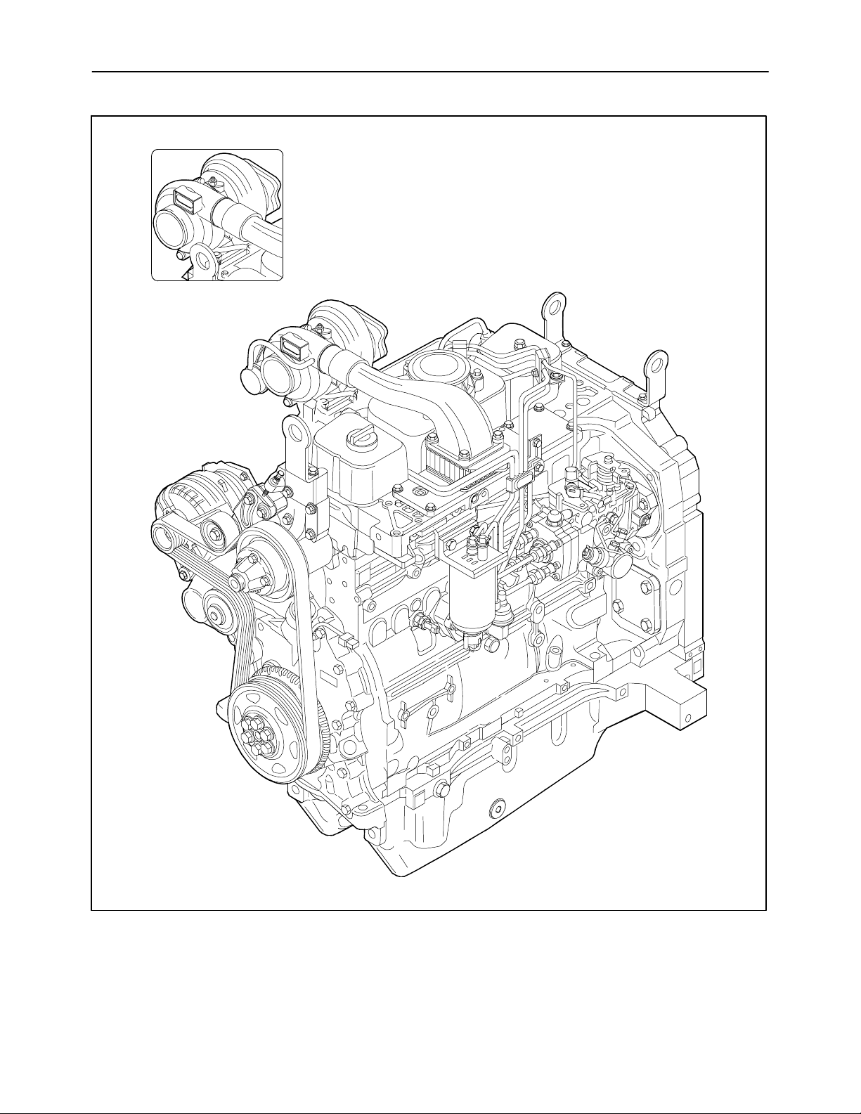
MIF1097A
1
View of Farmall 90 tractor engines of 65 kW (88 HP) and Farmall 95 of 70 kW (95 HP)
Page 16
16
SECTION 10 -- ENGINE -- CHAPTER 1
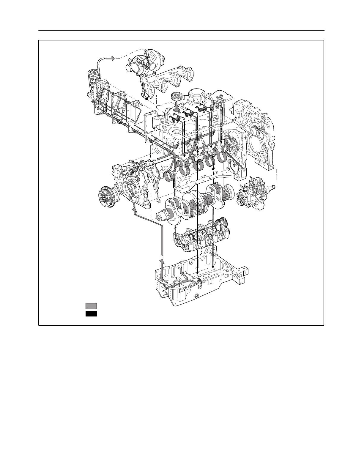
Oil path under pressure
Oil return path under gravity
MIF1098A
Lubrication diagram for engines mod. Farmall 90 and Farmall 95
Forced--circulation lubrication is accomplished by
the following components:
-- oil pump, housed at the front of the crankcase,
driven by the grooved bushing keyed onto the
shank of the crankshaft;
-- water / oil cooler, housed in the crankcase;
2
-- oil pressure control valve incorporated in the
cooler assembly;
-- by--pass valve to cut off clogged oil filter, incorporated in the cooler assembly;
-- cartridge oil filter.
Page 17
SECTION 10 -- ENGINE -- CHAPTER 1
17
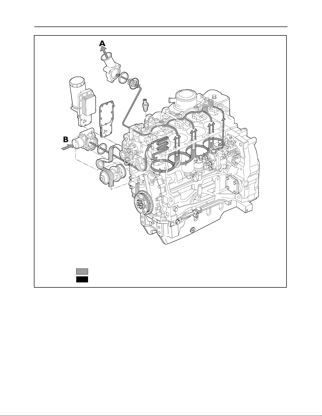
Coolant recirculating in the engine
Coolant entering the pump
MIF1099A
Cooling system diagram
The forced circulation, closed--circuit engine cooling
system is composed of the following components:
-- a lubricating oil cooler;
3
-- a centrifugal coolant pump housed at the front of
the crankcase;
-- a thermostat valve governing coolant circulation.
Page 18
18
SECTION 10 -- ENGINE -- CHAPTER 1
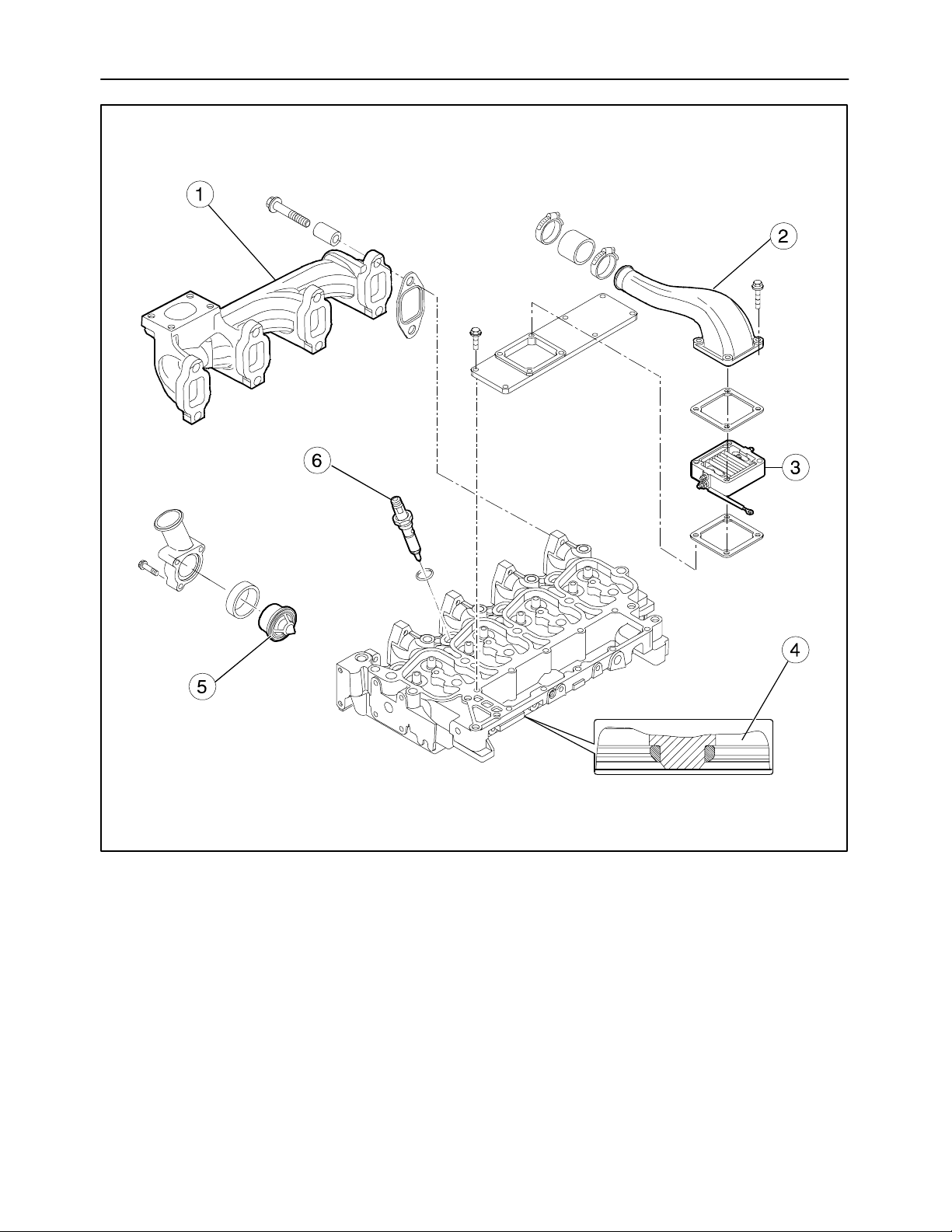
MIF1101A
Detail of cylinder head with valve seats fitted in engines mod. Farmall 90, Farmall 95
1. Exhaust manifold
2. Intake manifold
3. Air heater
4
4. Fitted valve seats
5. Thermostat valve
6. Injector
Page 19
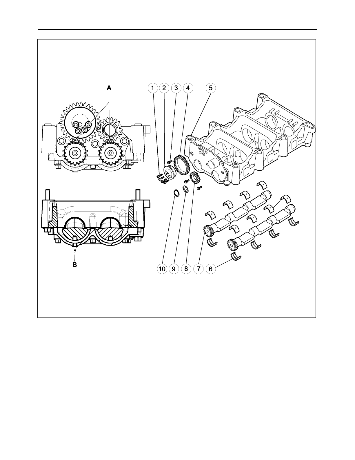
SECTION 10 -- ENGINE -- CHAPTER 1
19
MIF1102A
1. Retaining bolts
2. Support
3. Retaining bolts
4. Gear
5. Balancing weight
5
Additional counterweights
6. Half bearings
7. Counter--shaft
8. Gear
9. Ring
10. O--Ring
Page 20
20
SECTION 10 -- ENGINE -- CHAPTER 1
TROUBLESHOOTING
Problems Possible Causes Solutions
Engine does not start. 1. Batteries partially discharged. Check and recharge batteries. Re-
place if necessary.
2. Battery terminal connections corroded or loose.
3. Injection pump timing incorrect. Adjust injection pump timing.
4. Impurities or water in fuel lines. Disconnect fuel lines from injection
5. No fuel in tank. Fill tank.
6. Fuel supply pump malfunction. Check and replace pump if neces-
7. Air in fuel system. Check fuel lines, unions, supply
8. Starter motor faulty. Repair or replace starter motor.
9. Thermostarter faulty. Check and replace thermostarter if
Engine stalls. 1. Idle speed too low. Adjust idle speed.
Clean, inspect and tighten terminal
nuts. Replace terminals and nuts if
excessively corroded.
pump and clean thoroughly. If necessary clean and dry the fuel tank.
sary.
pump, filters and injection pump for
air; then bleed the air from the circuit.
necessary.
2. Injection pump delivery irregular. Check injection pump delivery on test
bench.
3. Impurities or water in fuel lines. Disconnect fuel lines from injection
pump and clean thoroughly. If necessary clean and dry the fuel tank.
4. Fuel filters clogged. Replace the filter cartridges.
5. Incorrect valve -- rocker arm
clearances.
6. Burnt or cracked valves. Replace the valves.
7. Air in fuel system. Check fuel lines, unions, supply
8. Injection pump drive mechanism
damaged.
Adjust the clearance between the
rocker arms and the valves.
pump, filters and injection pump for
air; then bleed the air from the circuit.
Replace damaged parts.
Page 21
SECTION 10 -- ENGINE -- CHAPTER 1
21
TROUBLESHOOTING (continued)
Problems Possible Causes Solutions
Engine overheating. 1. Coolant pump malfunction. Overhaul pump and replace if neces-
sary.
2. Thermostat faulty. Replace the thermostat.
3. Radiator inefficient. Remove internal deposits by flushing.
Check for leaks and repair.
Engine lacks power and
runs unevenly.
4. Deposits in cylinder head and
crankcase coolant passages.
5. Coolant pump and fan drive belt
slack.
6. Coolant level low. Top up expansion tank with specified
7. Incorrect engine timing. Check and adjust engine timing.
8. Injection pump calibration incorrect -- delivering too much or too
little fuel.
9. Air filter clogged. Clean filter unit and replace filter el-
1. Injection pump timing incorrect. Adjust injection pump timing.
2. Auto advance regulator in injection pump damaged.
Flush out coolant system.
Check and adjust belt tension.
coolant mixture.
Calibrate pump on test bench to values specified in calibration tables.
ement if necessary.
Overhaul injection pump and adjust
on test bench to values specified in
calibration table.
3. Control valve journal worn. Overhaul injection pump and adjust
on test bench to values specified in
calibration table.
4. Injection pump delivery irregular. Overhaul injection pump and adjust
on test bench to values specified in
calibration table.
5. All--speed governor damaged. Overhaul injection pump and adjust
on test bench to values specified in
calibration table.
6. Injectors partially obstructed or
damaged.
7. Impurities or water in fuel lines. Disconnect fuel lines from injection
Clean and overhaul injectors and adjust pressure setting.
pump and clean thoroughly. If
necessary clean and dry the fuel tank.
Page 22
22
SECTION 10 -- ENGINE -- CHAPTER 1
TROUBLESHOOTING (continued)
Problems Possible Causes Solutions
8. Fuel supply pump damaged. Replace fuel supply pump.
Engine produces abnormal
knocking noises.
9. Incorrect valve -- rocker arm
clearances.
10. Cylinder compression low. Test compression and overhaul en-
11. Air filter clogged. Clean filter unit and replace filter ele-
12. Tie--rod in linkage between accelerator and injection pump incorrectly adjusted.
13. Fast idling speed screw on injection pump incorrectly adjusted.
1. Injectors partially obstructed or
damaged.
2. Impurities accumulating in fuel
lines.
3. Injection pump timing incorrect. Adjust injection pump timing.
4. Crankshaft knocking due to excessive play in one or more main
or big--end bearings or excessive
endfloat.
Adjust the clearance between the
rocker arms and the valves.
gine if necessary.
ment if necessary.
Adjust to correct length.
Adjust fast idling speed screw.
Clean and overhaul injectors and adjust pressure setting.
Clean fuel lines and replace severely
dented pipes; clean injection pump if
necessary.
Re--grind crankshaft journals and
crankpins. Fit oversize shell bearings
and thrust washers.
5. Crankshaft out of balance. Check crankshaft alignment and bal-
ance; replace if necessary.
6. Flywheel bolts loose. Replace any bolts that have worked
loose and tighten all bolts to the specified preliminary and angular torque
values.
7. Connecting rod axes not parallel. Straighten connecting rods, check
axes parallelism; replace con rods if
necessary.
8. Pistons knock due to excessive
wear.
9. Noise caused by excessive play
of gudgeon pins in small--end and
piston bushings. Loose fit of
small--end bushing.
10. Excessive tappet / valve noise. Check for broken springs or exces-
Rebore cylinder liners and fit oversize
pistons.
Fit oversize gudgeon pin, rebore piston seats and small--end bushings.
Replace with new bushings.
sive play between valve stems and
guides, cam followers and bores; adjust valve clearances.
Page 23
SECTION 10 -- ENGINE -- CHAPTER 1
TROUBLESHOOTING (continued)
Problems Possible Causes Solutions
23
Engine produces excessive
black or dark grey smoke.
1. Maximum delivery of injection
pump too high.
2. Injection pump delivery excessively retarded or automatic advance regulator damaged.
3. Injection pump delivery excessively advanced.
4. Injectors partially or totally obstructed or incorrectly adjusted.
5. Air filter clogged. Clean filter unit and replace filter el-
6. Loss of engine compression due
to:
-- piston rings sticking;
-- cylinder liner wear;
-- worn or incorrectly adjusted
valves.
7. High--pressure fuel lines damaged.
Calibrate pump on test bench to values specified in calibration tables.
Adjust injection pump timing or check
automatic advance regulator.
Adjust injection pump timing.
Clean and overhaul injectors and adjust pressure setting; replace if
necessary.
ement if necessary.
Replace damaged parts or, if necessary, overhaul the engine.
Inspect and replace if necessary.
Blue, grey--blue or grey-white smoke.
Engine runs on after
switching off.
1. Injection pump delivery excessively retarded or automatic advance regulator damaged.
2. Injectors obstructed or damaged. Clean, overhaul and calibrate injec-
3. Oil leaking past piston rings due
to sticking rings or cylinder liner
wear.
4. Oil leaking through the inlet valve
guides due to guide or valve stem
wear.
5. Engine does not reach correct
operating temperature (thermostat faulty).
1. Engine stop electromagnet damaged.
2. All--speed governor damaged. Overhaul injection pump and adjust
Adjust injection pump timing or check
automatic advance regulator.
tors, replace if necessary.
Replace damaged parts or, if necessary, overhaul the engine.
Overhaul cylinder head.
Replace the thermostat.
Replace electromagnet.
on test bench to values specified in
calibration table.
Page 24
24
SECTION 10 -- ENGINE -- CHAPTER 1
OVERHAUL
Op 10 001 10
ENGINE
Removal
DANGER
Lift and handle all heavy parts using suitable lifting equipment.
Make sure that assemblies or parts are supported by means of suitable slings and hooks.
Check that no one is in the vicinity of the load to
be lifted.
WARNING
Always use appropriate tools to align fixing
holes. NEVER USE FINGERS OR HANDS.
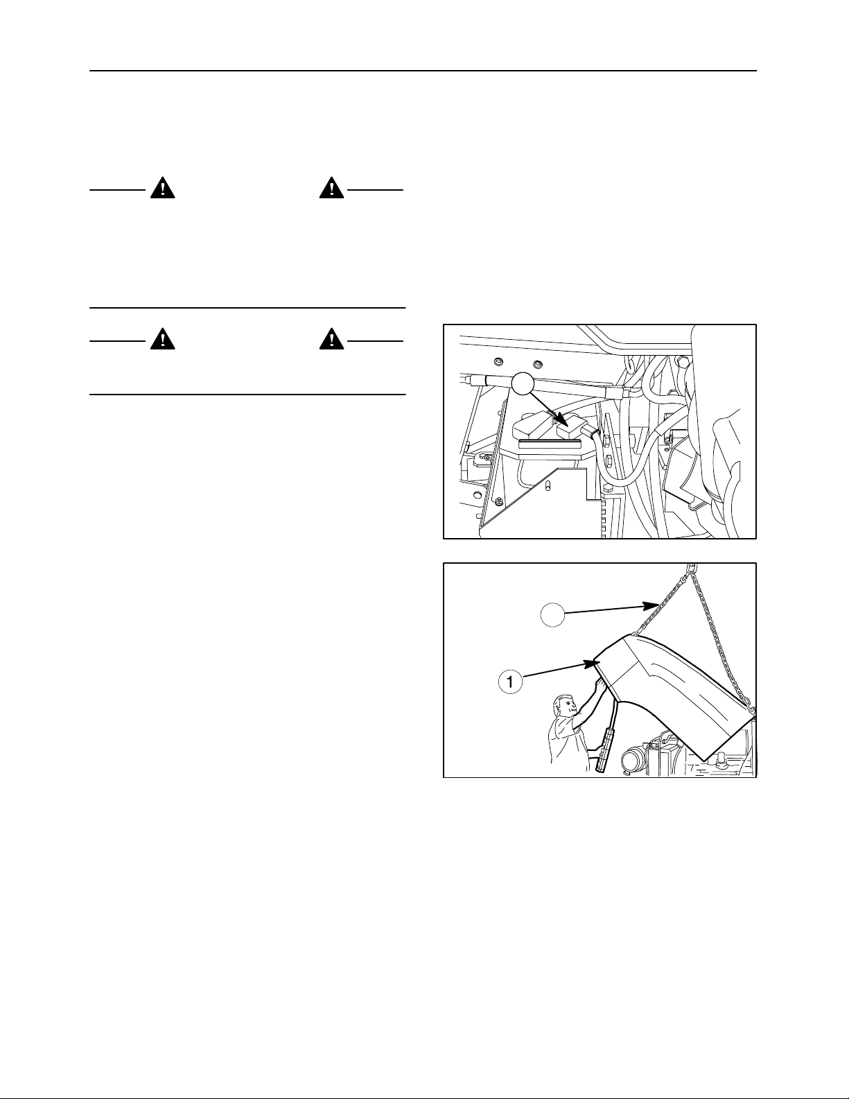
1. Disconnect the battery negative lead (1).
2. Drain the oil from the transmission--gearbox
housing.
1
3. Drain the cooling system.
4. Remove the exhaust pipe, attach lifting chains
(2) to the hood (1) and attach the chain to the
hoist.
6
2
7
Page 25
SECTION 10 -- ENGINE -- CHAPTER 1
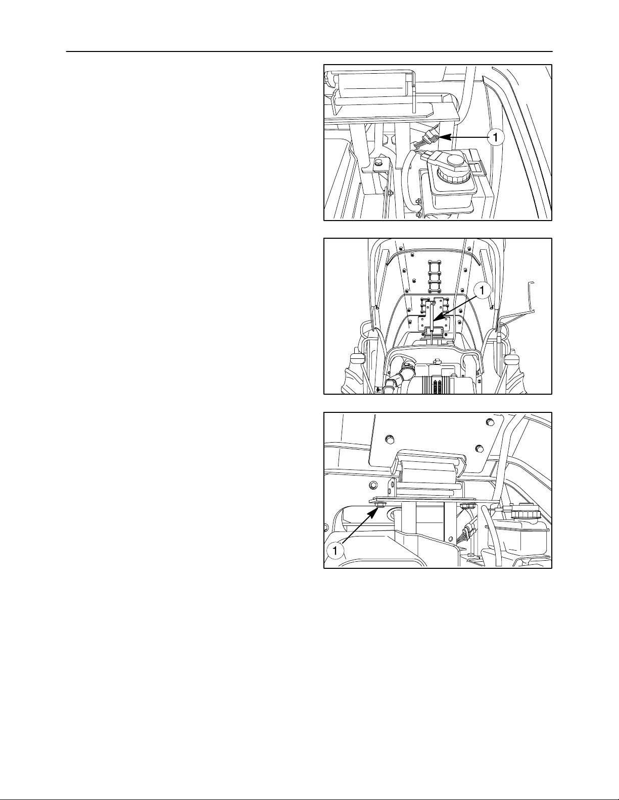
5. Disconnect the electrical connection (1) of hood.
6. Detach the gas struts (1) from the hood.
25
8
7. Remove the four hood hinge bolts (1) and lift the
hood clear.
9
10
Page 26
26
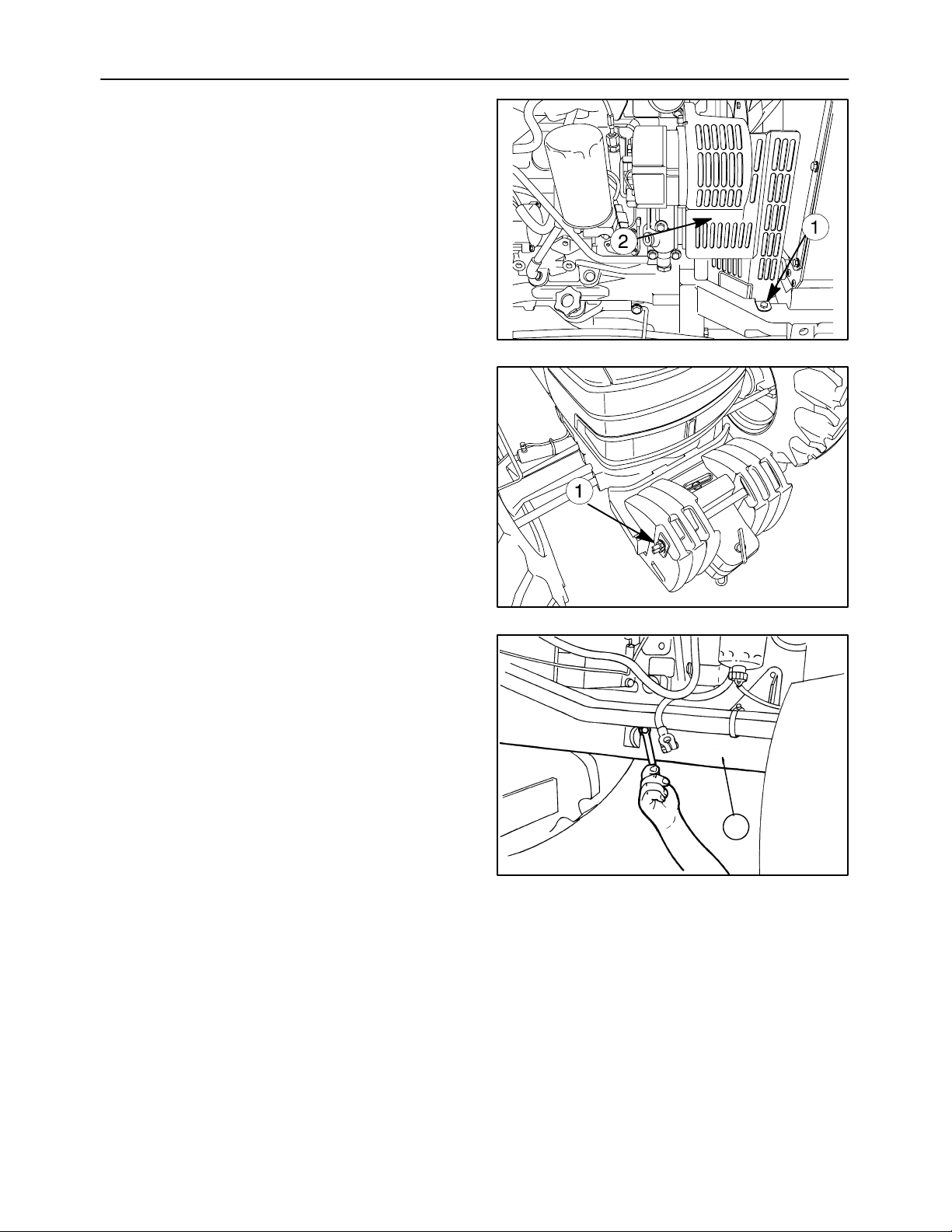
8. Remove the three retaining bolts (1) and the
guard (2) on the right--left hand side of the fan.
9. Unscrew the nut (1) from the weight retaining pin.
Remove the weights from the front support.
SECTION 10 -- ENGINE -- CHAPTER 1
11
10. Unscrew the front central and rear retaining bolts
on the front axle shaft guard, then remove the
guard (1).
12
1
25038
13
Page 27
SECTION 10 -- ENGINE -- CHAPTER 1
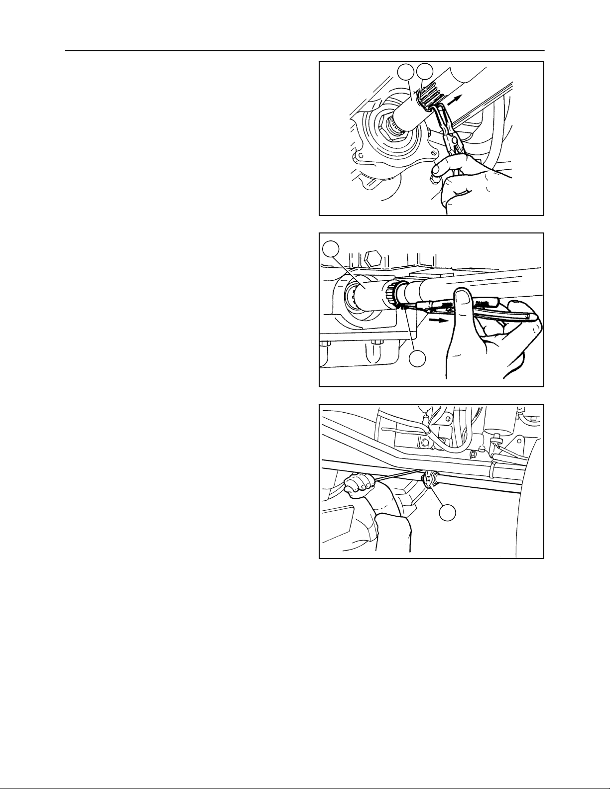
27
11. Remove the circlip (2) and move the front sleeve
(1) in the direction indicated by the arrow until it
is released from the groove on the front axle.
12. Remove the circlip (2) and move the rear sleeve
(1) in the direction indicated by the arrow until it
is released from the groove on the drive.
25039
1
2
1
14
13. Remove the propeller shaft central support (1)
retaining bolts and extract the shaft together with
the support.
2
25040
15
1
25041
16
Page 28
28
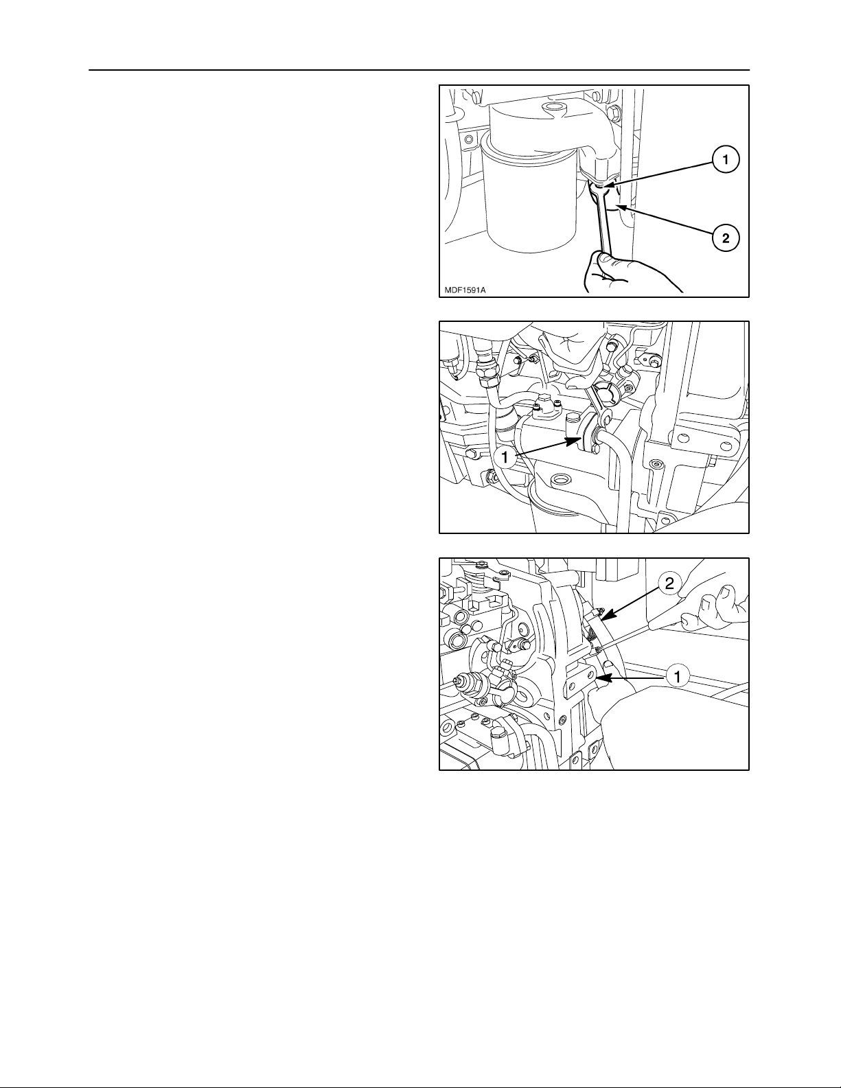
14. Remove the retaining bolts (1) of the suction pipe
(2) of the lift pump.
15. Disconnect the delivery and return lines from the
hydraulic lift pump.
SECTION 10 -- ENGINE -- CHAPTER 1
17
16. Detach the cab heating pipes (1) and (2).
18
19
Page 29
SECTION 10 -- ENGINE -- CHAPTER 1
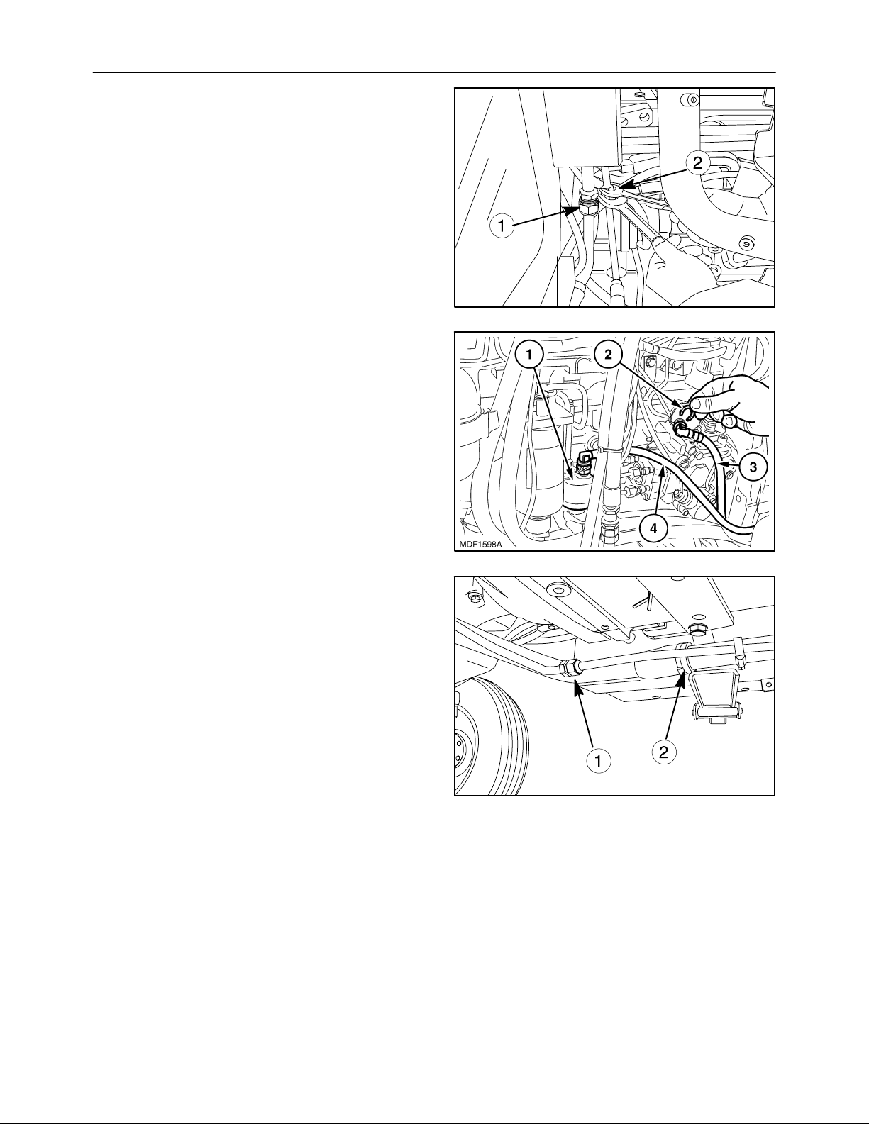
17. Detach the cab air--conditioning pipes (1) and
(2).
18. Extract the plastic fasteners (2) and detach the
diesel recovery pipe (3) and delivery pipe (4) to
the diesel pump (1).
29
20
19. Remove two metal clamps (2) and the rigid pipe
of drawing oil from the transmission housing via
lift pump (1) and power steering pump. Remove
the fitting of the delivery pipe.
21
22
Page 30
30
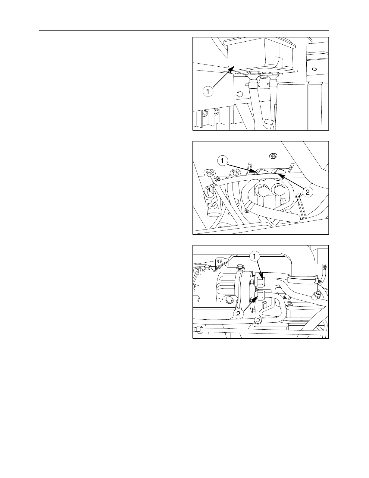
20. Remove the electrical connection from the brake
fluid reservoir and take the brake fluid reservoir
(1) from the bracket.
21. Disconnect the steering oil delivery and return
hoses (1) and (2).
SECTION 10 -- ENGINE -- CHAPTER 1
23
22. Disconnect A/C compressor inlet (2) and outlet
(1) hoses.
24
25
Page 31
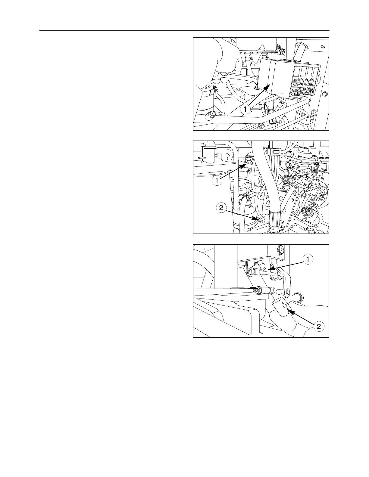
SECTION 10 -- ENGINE -- CHAPTER 1
23. Remove the fusebox (1) from the hood support.
24. Remove the electrical connections of temperature sender (1) and oil switch (2).
31
26
25. Remove the retaining retaining clips (1) and detach the flexible cables governing the hand
throttle and pedal throttle.
26. Remove the retaining clip (2) and detach the
throttle control tie--rod connected to the injection
pump.
27
28
Page 32
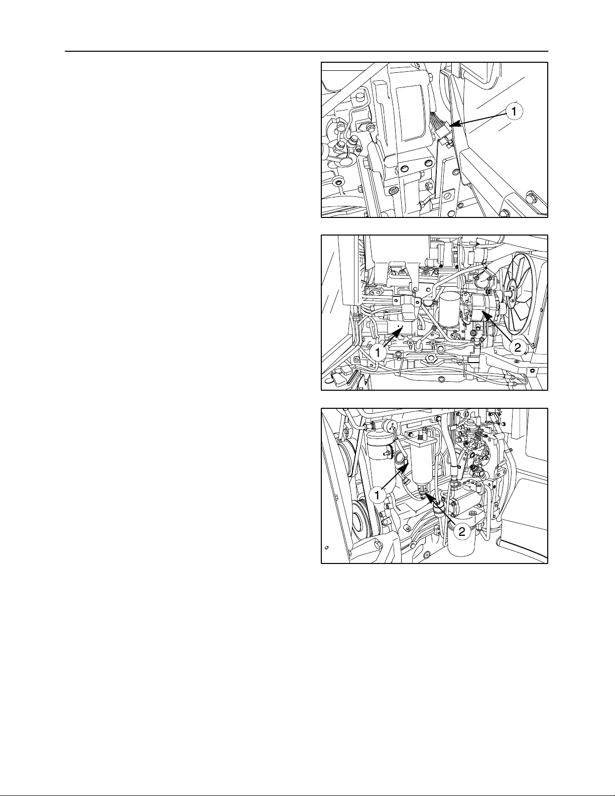
32
27. Disconnect the electrical connection (1) between
the cab and the engine.
28. Disconnect the electrical connections from alternator (1) and starter motor (2).
SECTION 10 -- ENGINE -- CHAPTER 1
29
29. Disconnect the electrical connections of dryer filter sensor (1) and water in fuel sensor (2).
30
31
Page 33
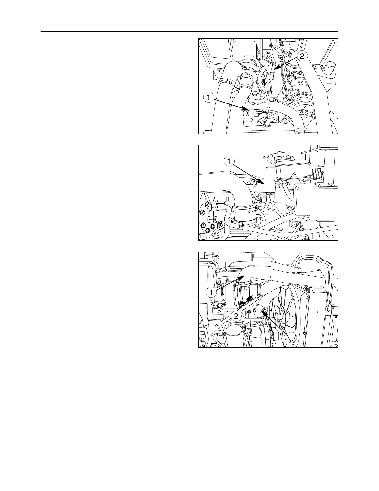
SECTION 10 -- ENGINE -- CHAPTER 1
30. Remove the electrical connection (1) and air filter
clogging sensor (2).
31. Remove the two retaining bolts and the support
together with relays protecting system (1).
33
32
32. Loosen the corresponding retaining clamps and
extract the pipes (1), (2) and (3).
33
3
34
Page 34
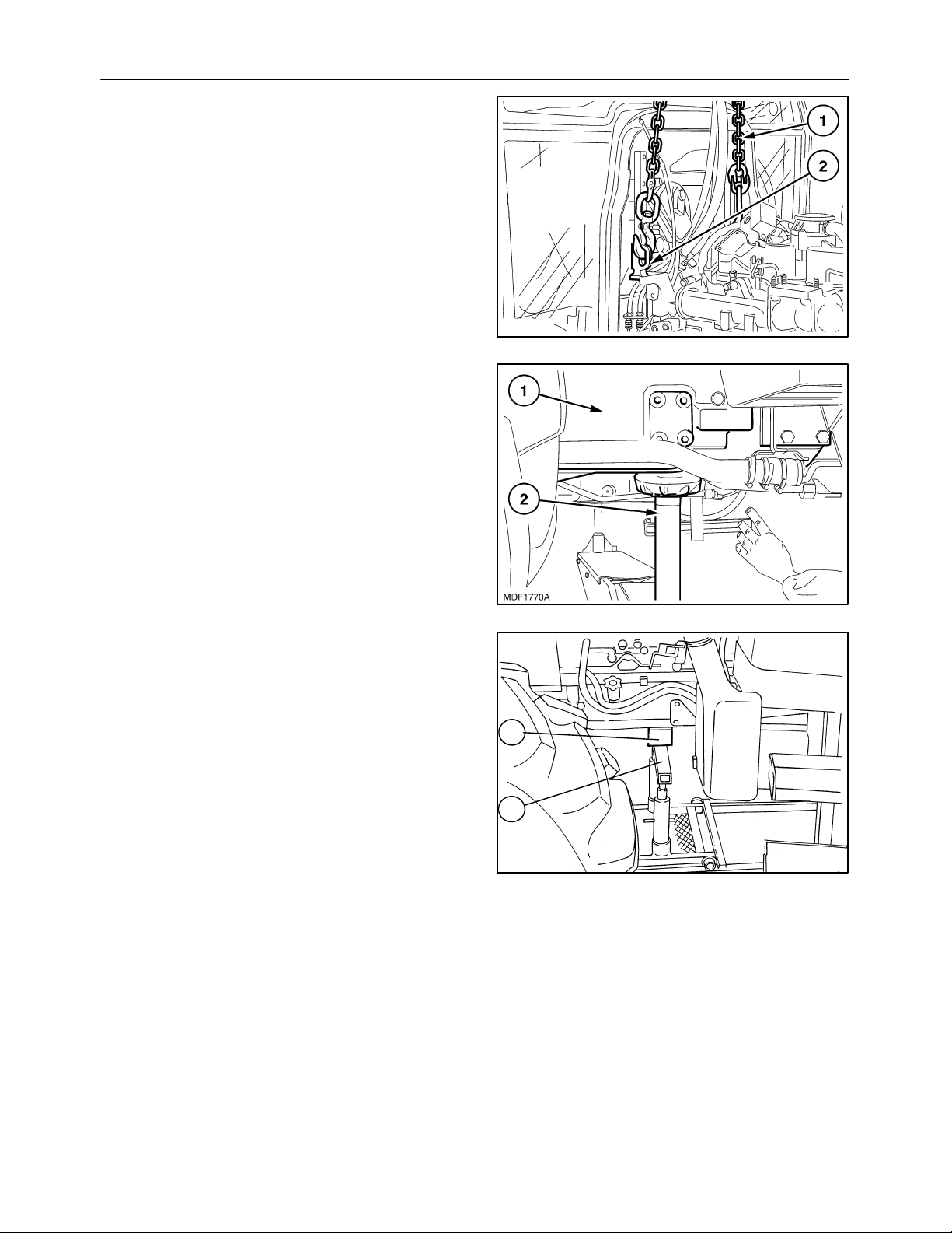
34
33. Hitch the engine to the hoist with the chains anchoring it to the attachments on the engine.
34. Position a fixed stand under the over drive clutch
housing near the engine attachment flanging and
apply the hand brake.
SECTION 10 -- ENGINE -- CHAPTER 1
35
35. Position the movable tool for dismantling tractors
380000569 with the bracket 380000500 and
adapter plate 380000844 under the engine and
place a wooden block in between the points of
contact between the tool and tractor.
36
1
2
37
Page 35
SECTION 10 -- ENGINE -- CHAPTER 1
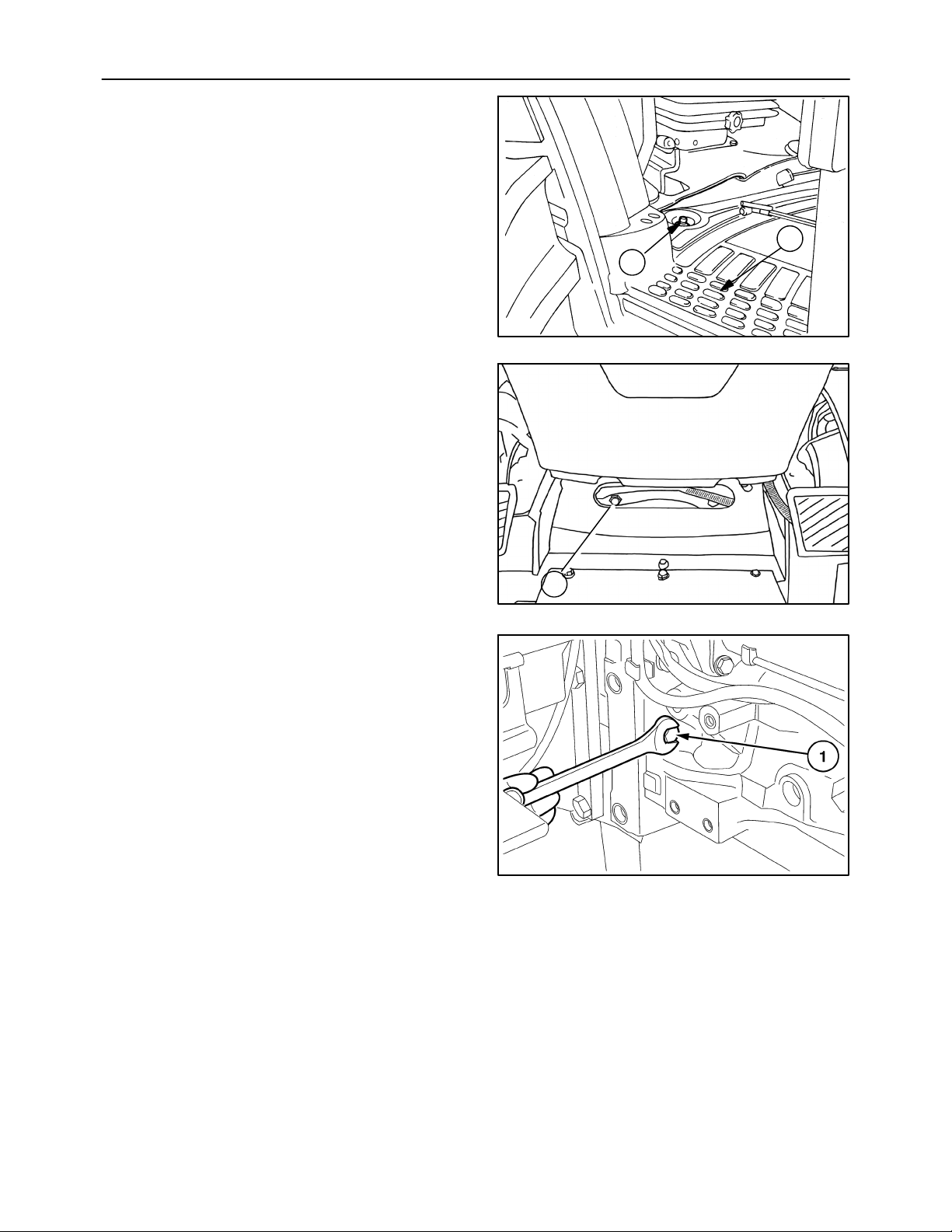
36. Extract the differential lock pedal retaining pin
from the drive shaft (1), remove the pedal and
footboard (2).
37. Unscrew the nuts (1) and the bolts securing the
engine to the transmission. Access is through the
two slots in the cab floor.
35
2
1
25043
38
38. Remove the remaining six retaining bolts at the
bottom and side.
1
39
40
Page 36
36
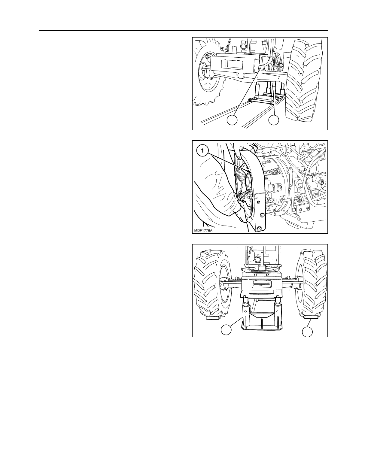
39. Separate the engine from the transmission with
the tool 380000569.
40. Remove the spacer located between the engine
and the transmission.
SECTION 10 -- ENGINE -- CHAPTER 1
1 2
41
41. Insert the fixed under the ballast support and secure the front wheels with wooden blocks.
42
1
2
43
Page 37
SECTION 10 -- ENGINE -- CHAPTER 1
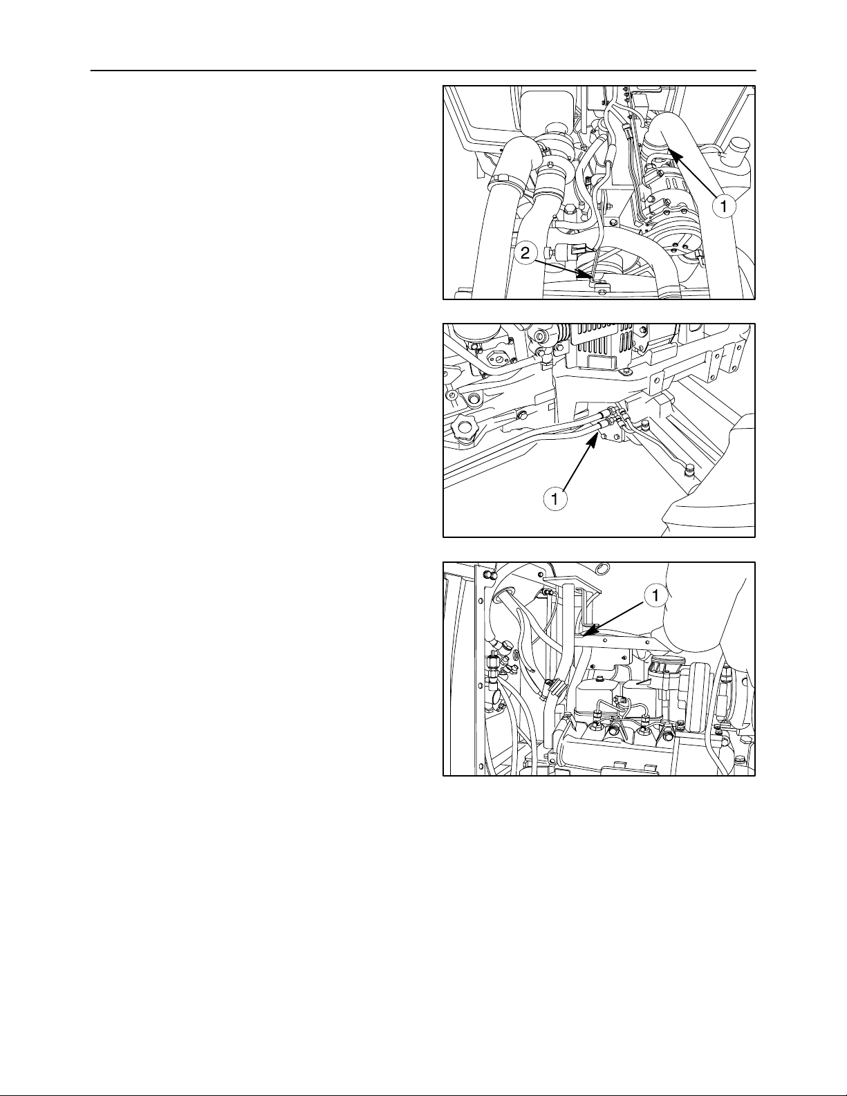
42. Loosen the corresponding retaining clamp (1)
and extract the pipes. And remove the bracket
(2).
43. Disconnect the delivery and return lines (1) to the
power steering cylinders.
37
44
44. Remove the hood support (1).
45
46
Page 38
38
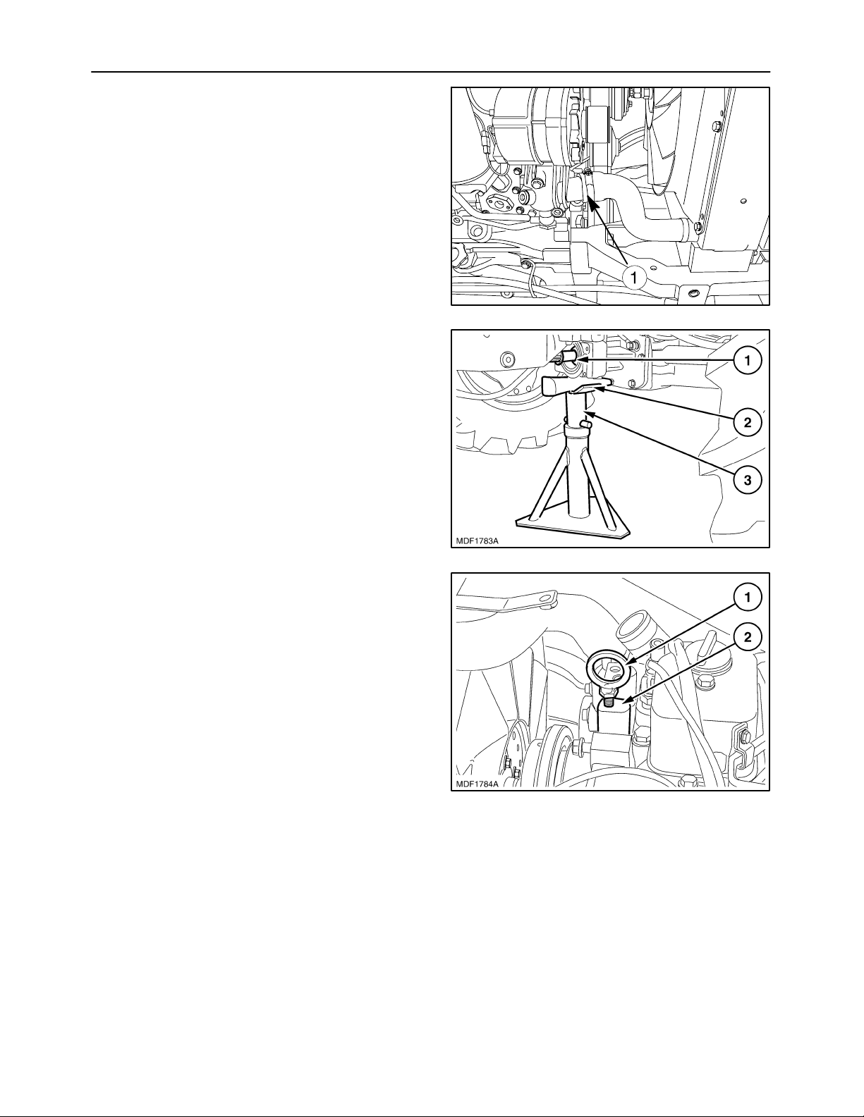
45. Loosen the retaining clamp and extract the pipe
(1) joining the coolant pump to the bottom of the
radiator.
46. Position a fixed stand (3) under the support of the
groove (1) of the front axle drive placing a wooden plug (2) between the parts (3) and (1).
SECTION 10 -- ENGINE -- CHAPTER 1
47
47. Fit the lifting eyelet (1) in the threading on the
support (2).
48
49
Page 39
SECTION 10 -- ENGINE -- CHAPTER 1
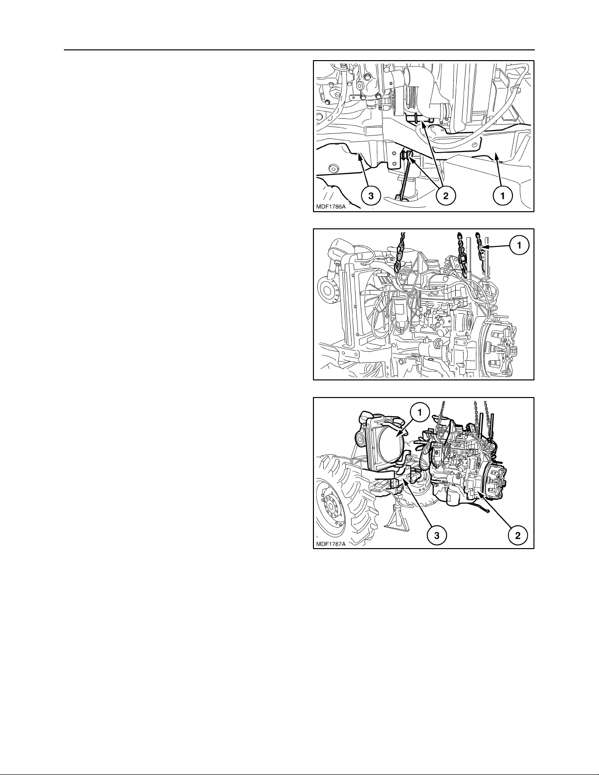
48. Remove the four bolts (2) fastening the front axle
support (1) to the engine (3).
49. Insert the hooks of the lifting chains (1) in the eyelets shown in the figure, afterwards tensioning
the chains with the hoist.
39
50
50. Detach the engine (2) from the front axle (3), trying to avoid incorrect operations with the hoist so
as not to let the engine fan damage the fins of the
radiator (1), left on the axle (3).
51. Then rest the engine on a platform support.
51
52
Page 40

40
Installation
SECTION 10 -- ENGINE -- CHAPTER 1
CAUTION
Always use appropriate tools to align fixing
holes. NEVER USE FINGERS OR HANDS.
1. Apply the torque settings listed on page 12.
2. Insert the three hooks of the chain in the eyelets
on the engine and, using the hoist, lift the assembly off the platform support.
3. Position the engine on the front axle, trying to
avoid incorrect operations with the hoist so as not
to let the engine fan damage the fins of the radiator, then join the two assemblies together with the
four retaining bolts.
4. Reposition the movable tool for dismantling tractors 380000569 under the engine and place a
wooden block in between the point of contact between the tool and engine.
5. With the aid of the hoist, place the engine on the
tool 380000569 and remove the lifting eyelet previously fitted on the front of the engine.
6. Remove the fixed stand previously positioned
under the support of the groove of the drive of the
front axle and the wooden plug.
7. Refit the pipe joining the coolant pump to the bottom of the radiator and the associated retaining
clamp.
8. Refit the oil vapor suction pipe, filter/intake manifold connecting pipe and the pipe connecting the
radiator at the top to the thermostat valve, re-installing the associated retaining clamps.
9. Fit the left--right hand side guard of the engine fan
and the three retaining bolts.
10. Remove the fixed U--bolt fitted beforehand under
the ballast support and the two wooden wedges
locking the front wheels.
11. Remove the old sealing compound from both
surfaces of the spacer between the engine and
the overdrive clutch housing, and do the same
also on the contact surface of the overdrive
clutch housing and on that of the engine.
12. Apply LOCTITE sealing compound on the engine/spacer contact surfaces and fit the spacer
on the stud bolts screwed into the engine.
13. Also apply LOCTITE sealing compound on the
clutch overdrive casing surfaces.
14. Position wooden blocks under the rear wheels,
make sure that the hand brake is fully applied and
that all fixed and mobile stands are safely positioned.
15. The installation phase described here requires
the presence of two or three workers to use the
movable tool for dismantling tractors 380000569
to move the engine/front axle assembly close to
the overdrive clutch casing.
16. In the phase of installing the engine/front axle assembly to the overdrive clutch casing, it is necessary to push on the front wheels, taking great
care in the end phase of coupling over both the
pipes and the cables/electrical connections to
prevent crushing between the two bodies. During
this phase, it is moreover necessary to turn the
crankshaft with the aid of the radiator cooling fan
to help the coupling between the sleeve and the
drive shaft.
17. Secure both assemblies by tightening all the
bolts locking the engine to the overdrive clutch
casing.
18. Remove the U--bolt previously fitted under the
clutch casing and recover the movable tool for
dismantling tractors 380000569.
19. Fit the electric cable connected to the fuse--holder box and the retaining nut.
20. Working from the side of the starter motor, fit the
protective cable housing and the retaining nut.
21. Fit the electrical connections installed on the
brake pump and on the brake fluid reservoir.
22. Refit the power steering piping on the engine and
reconnect the electrical connections to the pressure switch.
23. Refit the power steering return pipe with its
bracket and retaining bolt.
24. Refit the brake piping support and the two retaining bolts.
25. Refit the condenser, air cooler and radiator
pipes.
26. Refit the dryer filter together with its support and
piping, tightening the two retaining bolts.
27. Refit the hood support, tightening the retaining
bolts.
28. Refit the support with the fuse--holder box on the
hood support, tightening the two retaining bolts.
29. Refit the support together with the relays protecting the system on the hood support, fitting the two
retaining bolts.
30. Refit the brake fluid reservoir onto the support
and the two retaining clips.
Page 41

SECTION 10 -- ENGINE -- CHAPTER 1
41
31. Refit the silencer together with the exhaust pipe.
32. Secure the silencer to the exhaust manifold with
the four nuts and connect the air filter dust extractor pipe to the silencer exhaust, inserting the retaining clamp.
33. Refit the three rear retaining bolts of the exhaust
silencer.
34. Fit the cab heater delivery and return pipes and
insert the associated clamps.
35. Refit the fitting of the hose delivering power
steering oil to the hydraulic cylinders governing
the front wheel steering.
36. Install the flexible cables governing the hand and
pedal throttle, inserting the retaining clips.
37. Reconnect the throttle control tie--rod to the injection pump, inserting the retaining clip.
38. Working from inside the cab, fit the four plugs to
gain access to the upper bolts securing the engine, located at the base of the steering column.
39. Refit the pedal on the differential lock drive shaft,
the retaining pin and the footboard.
40. Refit the two right-- and left--hand dashboard
panels and the relevant four fixing knobs.
41. Refit the two power steering cylinder oil delivery
and return hoses.
44. Working on the left--hand side of the engine,
install the lift pump draw pipe and tighten the retaining bolts.
45. Install the delivery pipe of the services pump on
the right--hand side of the engine and tighten its
fitting.
46. Refit the rigid pipe for drawing oil from the transmission and the two metal clamps.
47. Refit the power steering/four--wheel drive drain
pipe on both the left-- and right--hand sides of the
engine.
48. Refit the lift pump draw pipe and lock the retaining bolts.
49. Refit the propeller shaft with its central support
and the retaining bolts.
50. Refit the front axle drive shaft guard, tightening
the front, central and rear retaining bolts.
51. Refit the front ballast together with the support
and insert the retaining pin and the split pins.
52. Install the fitting of the cab heater radiator coolant
return pipe connected to the bottom of the coolant pump and refill the engine coolant.
53. Refit the guard on the right--hand side of the fan,
tightening the three retaining bolts.
54. Refill the transmission--gearbox housing with oil.
42. Install the electrical connections between the
cab and the engine.
43. Reconnect the diesel delivery and return pipes to
the diesel pump and install the relevant plastic
fasteners.
55. Install the hood. Reconnect the battery negative
lead.
Page 42
42
SECTION 10 -- ENGINE -- CHAPTER 1
Op 10 001 53
Disassembly
CAUTION
Handle all parts carefully. Do not put your hands
or fingers between parts. Wear the prescribed
safety clothing, including goggles, gloves and
safety footwear.
1. Remove the engine as described in operation
10 001 10, proceed as follows.
2. Drain off the engine oil by removing the plug from
the sump and the oil filler plug.
3. Detach the fan unit from the fan pulley.
4. To be able to fit the bracket 380000661 (for fixing
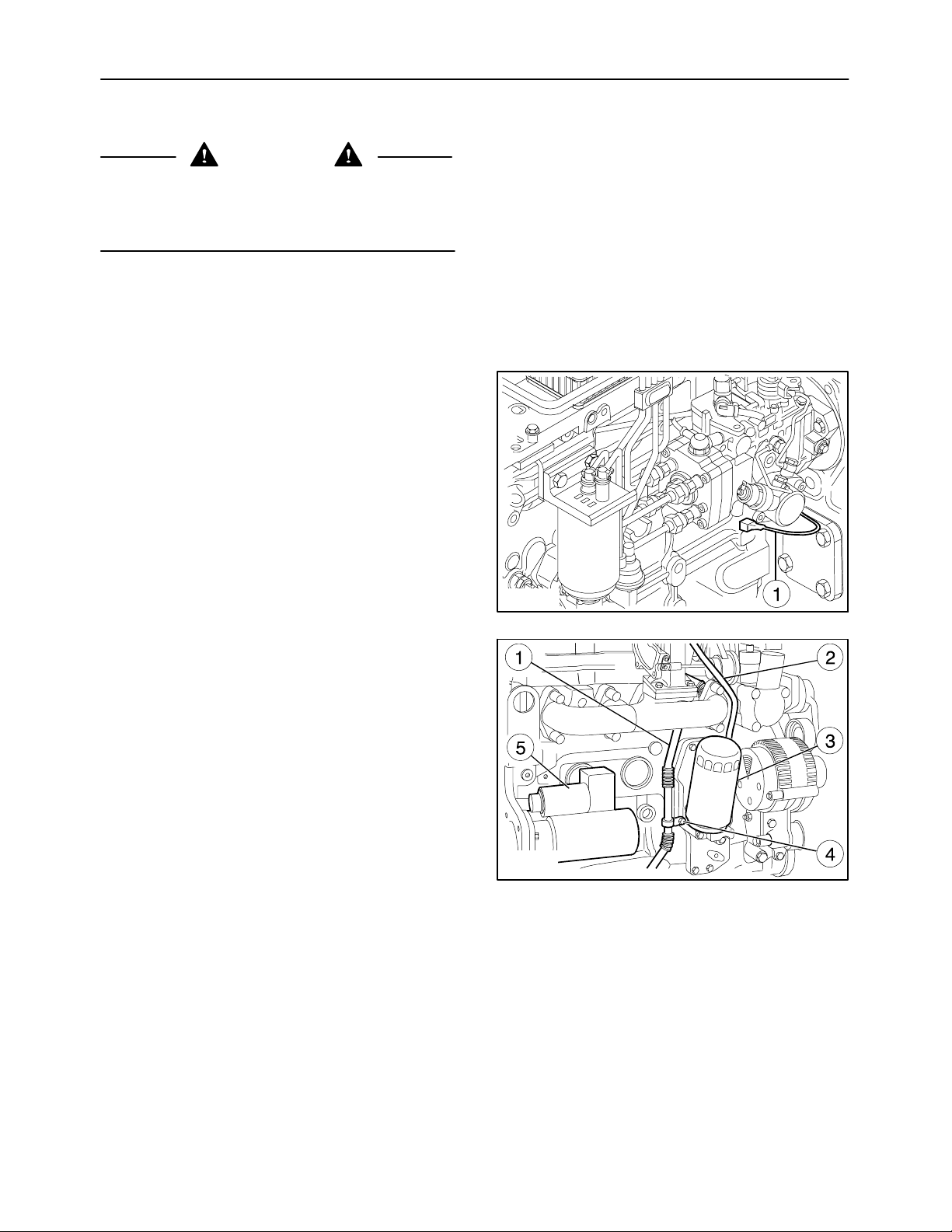
the engine to the overhaul stand) to the crankcase, it is necessaryto remove the wiring(1) from
the left--hand side of the engine.
5. To be able to fit the bracket 380000661 to the
crankcase on the right--hand side, remove the
starter motor (5), oil filter (3), clamp (4), and turbine oil return pipe (1).
6. Secure the engine to the rotary stand 380000301.
Remove the oil delivery pipe (2).
MIF1103A
53
MIF1104A
54
Page 43
SECTION 10 -- ENGINE -- CHAPTER 1
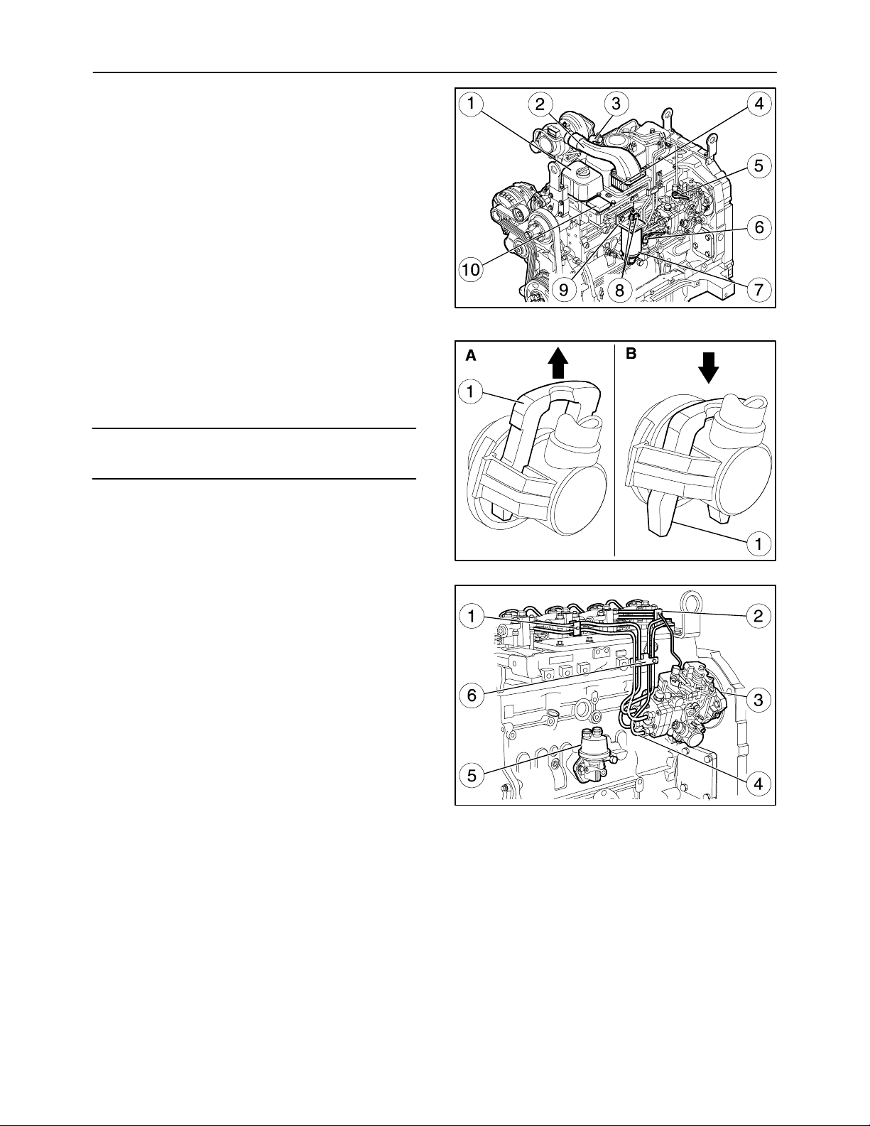
7. Remove the intake manifold (2).
8. Disconnect the engine oil vapor recovery pipe
from the blow--by (3).
9. Remove the tappet covers (1).
10. Remove the pipes with the quick--fit coupling (6)
and (8).
11. Remove the piping from the LDA system (5).
12. Remove the fuel filter (7).
13. Remove the heater (4).
14. Remove the control unit for the heater (10).
15. Remove the fuel filter support (9).
16. Act on the fork (1) as shown in the figure 56
(part B) and remove the fitting. Toavoid deformation, with the fitting removed, put the fork (1) back
in the locking position (part A).
NOTE: Figure 56 shows the connectors for the low-pressure pipes (6 and 8, figure. 55).
43
MIF1105A
55
A=Pipe locking position on connector.
B=Pipe removal position on connector.
17. Remove the injector feed pipe (4) from the injection pump (3).
18. Remove the brackets on the cylinder head of the
pipe assembly (1), (2) and (6).
19. Remove the priming pump (5).
MIF0909A
56
MIF1107A
57
Page 44
44
SECTION 10 -- ENGINE -- CHAPTER 1
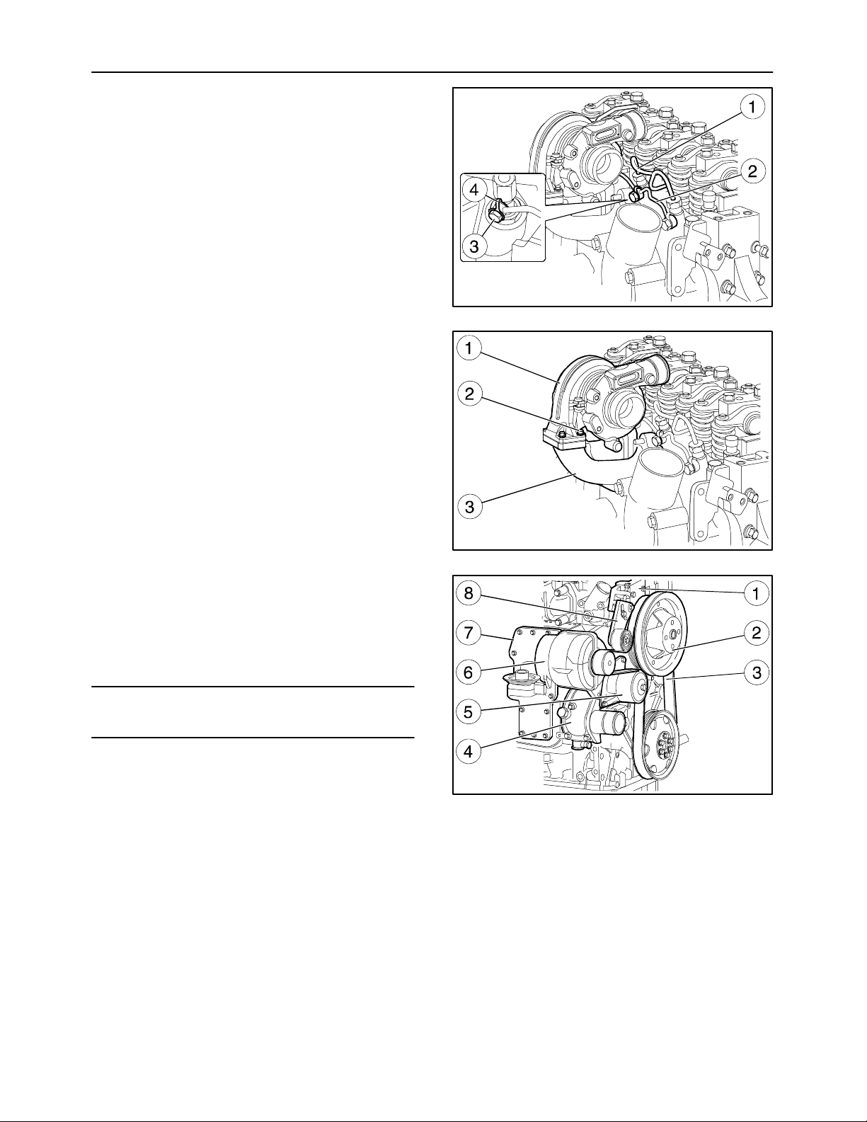
20. Detach the fuel pipe assembly (1) from the injectors.
21. Remove the fuel outlet pipe (2) from the injectors
removing the screw (3) and the seal (4).
22. Remove the screws (2) and the turbine (1).
23. Remove the exhaust manifold (3).
24. Remove the belt (3, fig. 60) of the auxiliary members by loosening the tightener.
MIF1108A
58
25. Remove the alternator (6), fan pulley (2). and
tightener (8). Remove the support (1) of the
pulley (2) and the oil cooler (7).
26. Remove the coolant pump (5).
27. Remove the engine cooling system fitting (4)
from the crankcase.
NOTE: The coolant pump (5) cannot be overhauled.
It must be replaced if there is any irregular operation.
MIF1109A
59
MIF1110A
60
Page 45
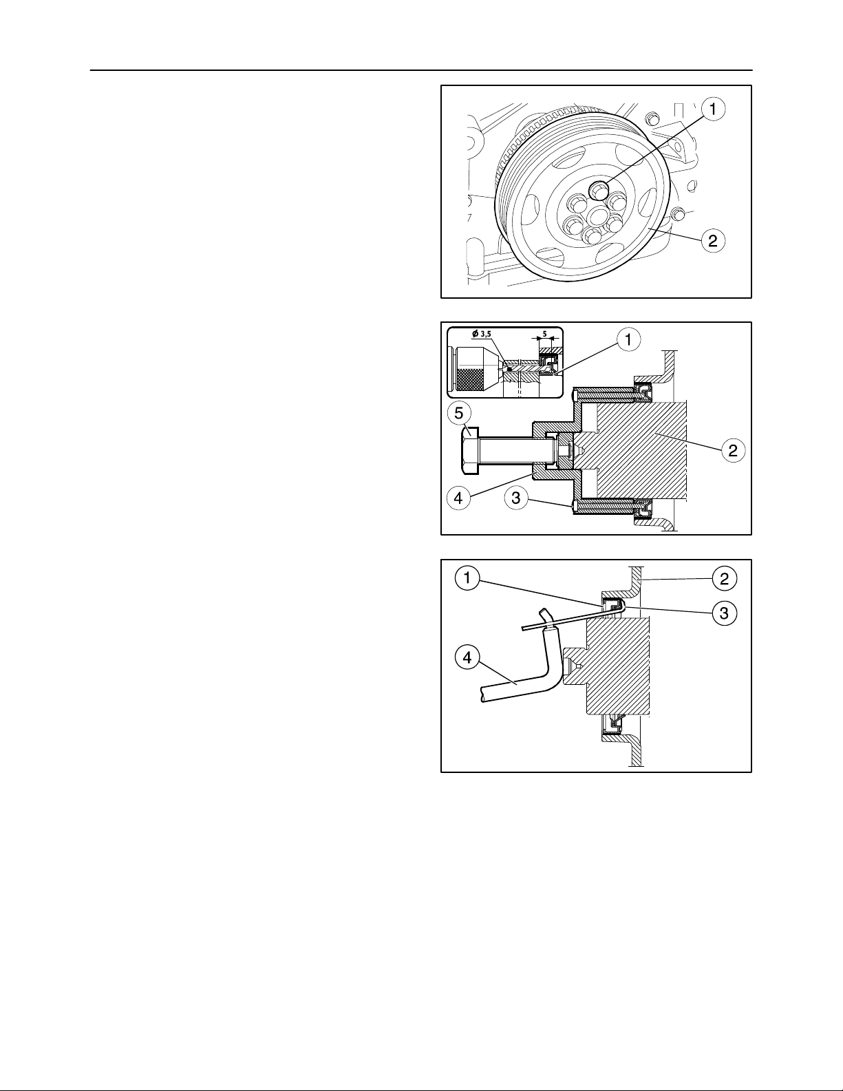
SECTION 10 -- ENGINE -- CHAPTER 1
28. Lock the flywheel to stop it turning, remove the
fixing screws (1) from the pulley (2).
Removing the Crankshaft Front Seal
(Op. 29. to 33.)
29. Apply tool 380000665 (4) on the front shank (2)
of the crankshaft.
30. Perforate the inner seal (1) with a drill bit
(∅ 0.1377 in. (3.5 mm) through the guide holes
of the tool 380000665 (4), for a depth of
0.1968 in. (5 mm).
31. Secure the tool 380000665 (4) to the seal (1) with
the screws (3) provided.
32. Extract the seal (1) by screwing down the screw
(5).
33. Fit the tie rod (3) of the tool 380000669 to the outer seal (1) as shown in the figure 63 and with the
lever (4), extract it from the front cover (2).
45
MI F 1111A
61
MIF0916A
62
MIF0917A
63
Page 46
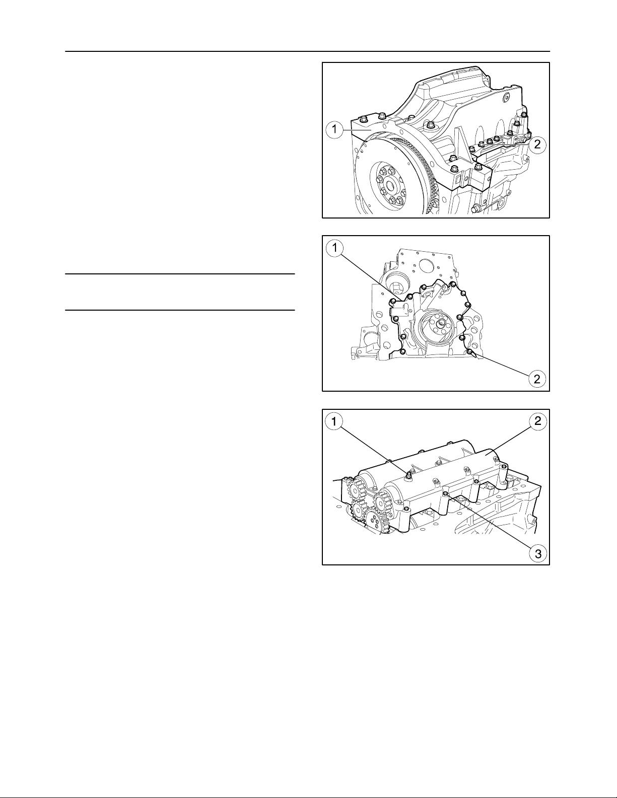
46
SECTION 10 -- ENGINE -- CHAPTER 1
34. Turn the engine over, take out the screws (2) and
remove the oil sump (1).
35. Take out the bolts (2) and remove the oil pump
(1).
NOTE: The oil pump (1) cannot be overhauled.
It must be replaced if there is any irregular operation.
MIF1117A
64
36. Using the pin (1), lock the additional counterweights (2) at the T.D.C.
Unscrew the retaining bolts (3) and remove the
additional counterweights (2).
MIF1112A
65
MIF1113A
66
Page 47
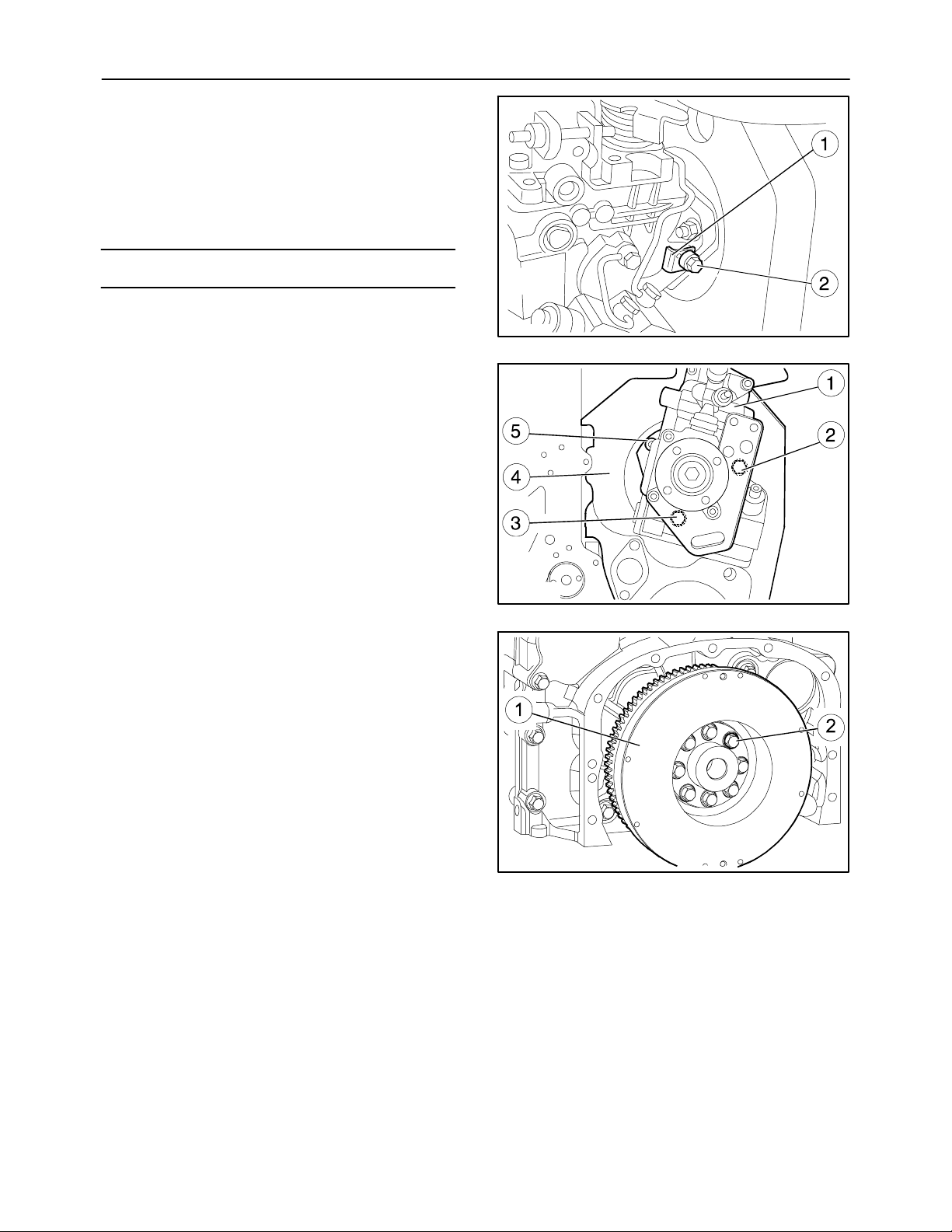
SECTION 10 -- ENGINE -- CHAPTER 1
37. Before removing the injection pump, do the timing and lock the engine flywheel with cylinder
no. 1 at T.D.C. as shown on page 100, using tools
380000988 and 380000732. Then loosen the
bolt (2), remove the “L” spacer (1) and lock the
screw (2) in order to keep the pump in time with
the engine flywheel.
NOTE: Keep the “L” spacer with the pump casing.
38. Remove the three nuts (2) (3) (5) securing the injection pump (1) to the crankcase (4) and extract
it from its housing.
47
MIF0920A
67
39. Remove the screws (2) fixing the engine flywheel
(1) to the crankshaft.
MIF0922A
68
MIF1115A
69
Page 48
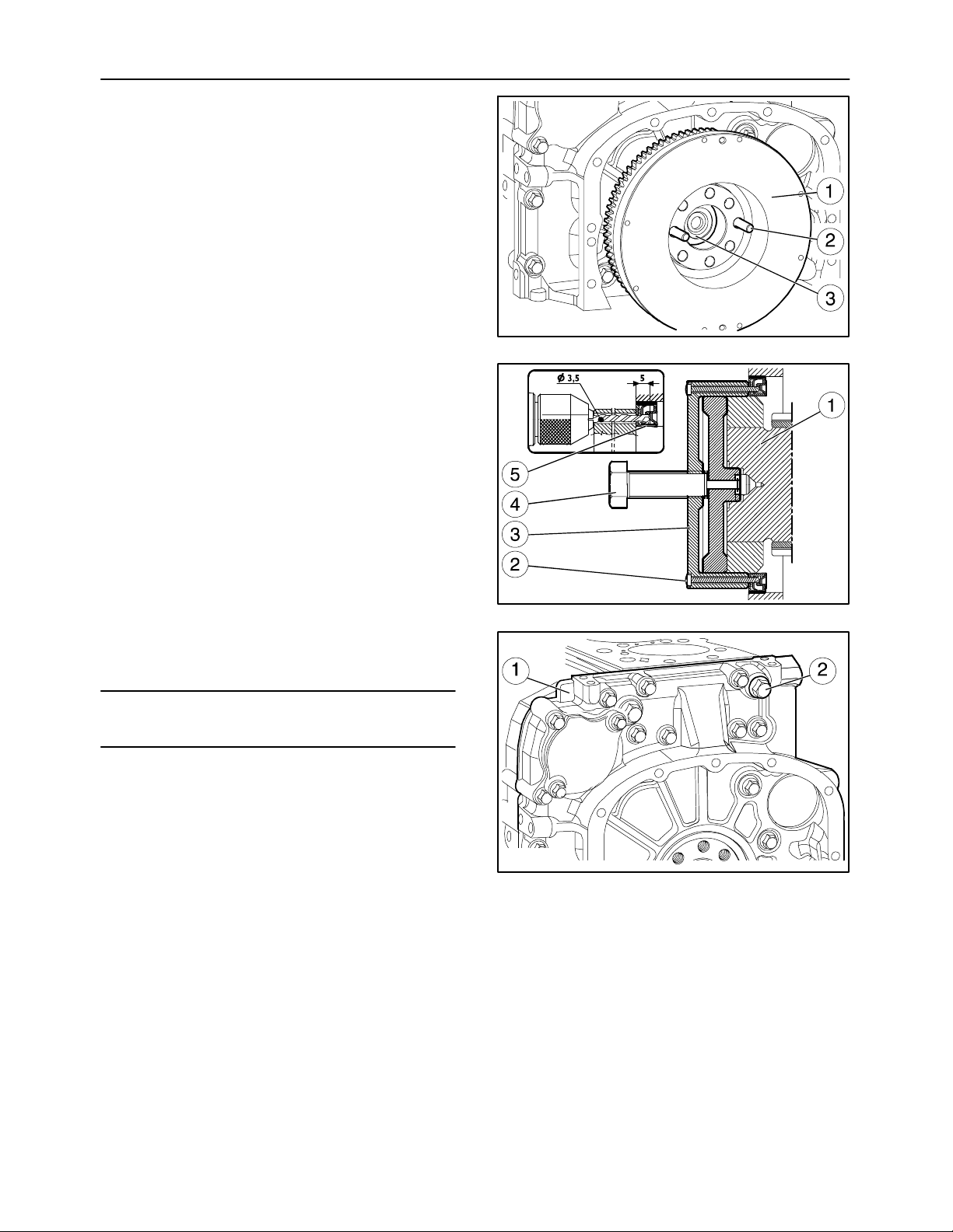
48
SECTION 10 -- ENGINE -- CHAPTER 1
40. Screw two pins (2) of the appropriate length into
the holes in the crankshaft (3).
41. Extract the engine flywheel (1) so it can be slung
with the lift and put it away in a specific container.
Removing the Crankshaft Rear Seal
(Op. 42. to 45.)
42. Extract the seal, applying tool 380000663 (3)
onto the rear shank (1) of the crankshaft.
43. Perforate the inner seal (5) with a drill bit
(∅ 0.1377 in. (3.5 mm)) through the guide holes
of the tool 380000663 (3), for a depth of
0.1968 in. (5 mm).
44. Secure the tool 380000663 (3) to the seal (5) by
screwing down the screws (2) supplied.
45. Extract the seal (5) by screwing down the screw
(4).
46. Take out the screws (2) and remove the timing
gear box (1), retrieving the injection pump gear.
MIF1116A
70
MIF0927A
71
NOTE: Note down the assembly position of the
screws (2) as they have different sizes.
MIF1125A
72
Page 49
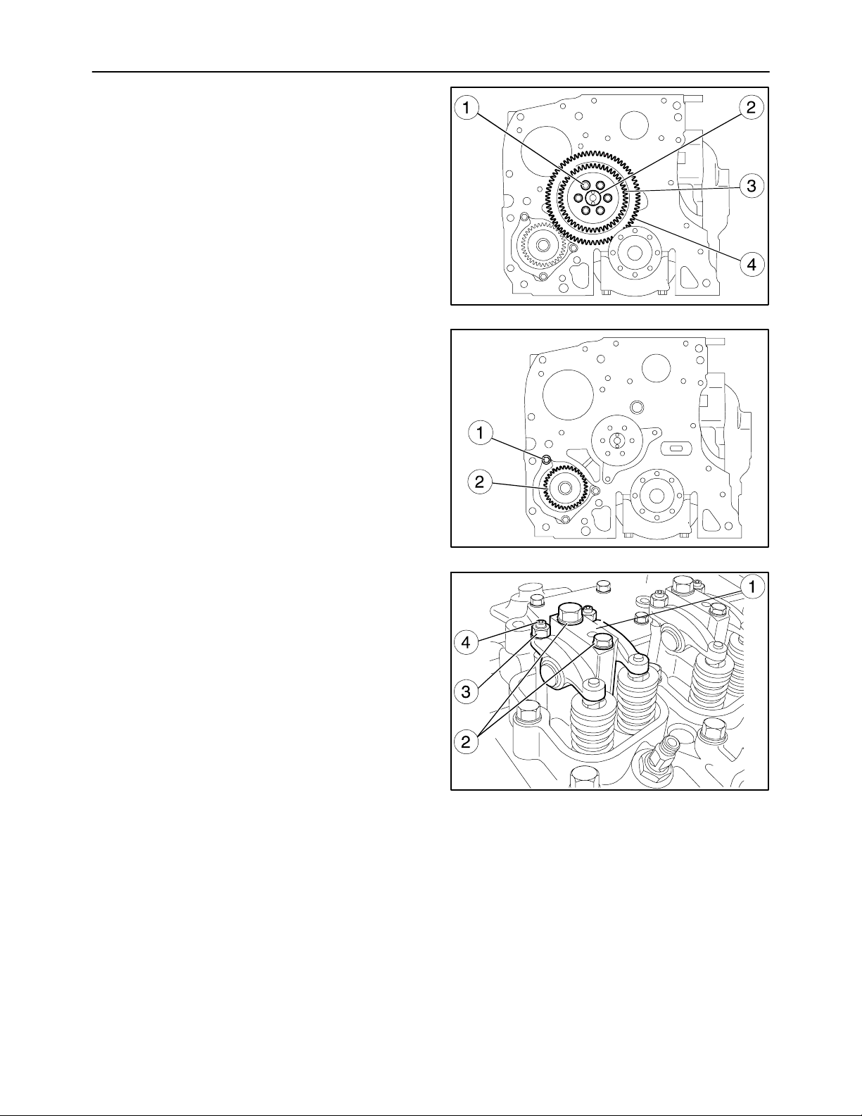
SECTION 10 -- ENGINE -- CHAPTER 1
47. Take out the screws (1) and remove the gears (3)
and (4) from the camshaft (2).
48. Take out the bolts (1) and remove the hydraulic
pump drive gear (2).
49
MIF1118A
73
49. For each cylinder, remove the rocker arm assembly (1) loosen the adjuster nuts (3), unscrew the
adjusters (4) and take out the screws (2).
MIF1119A
74
MIF0933A
75
Page 50
50
SECTION 10 -- ENGINE -- CHAPTER 1
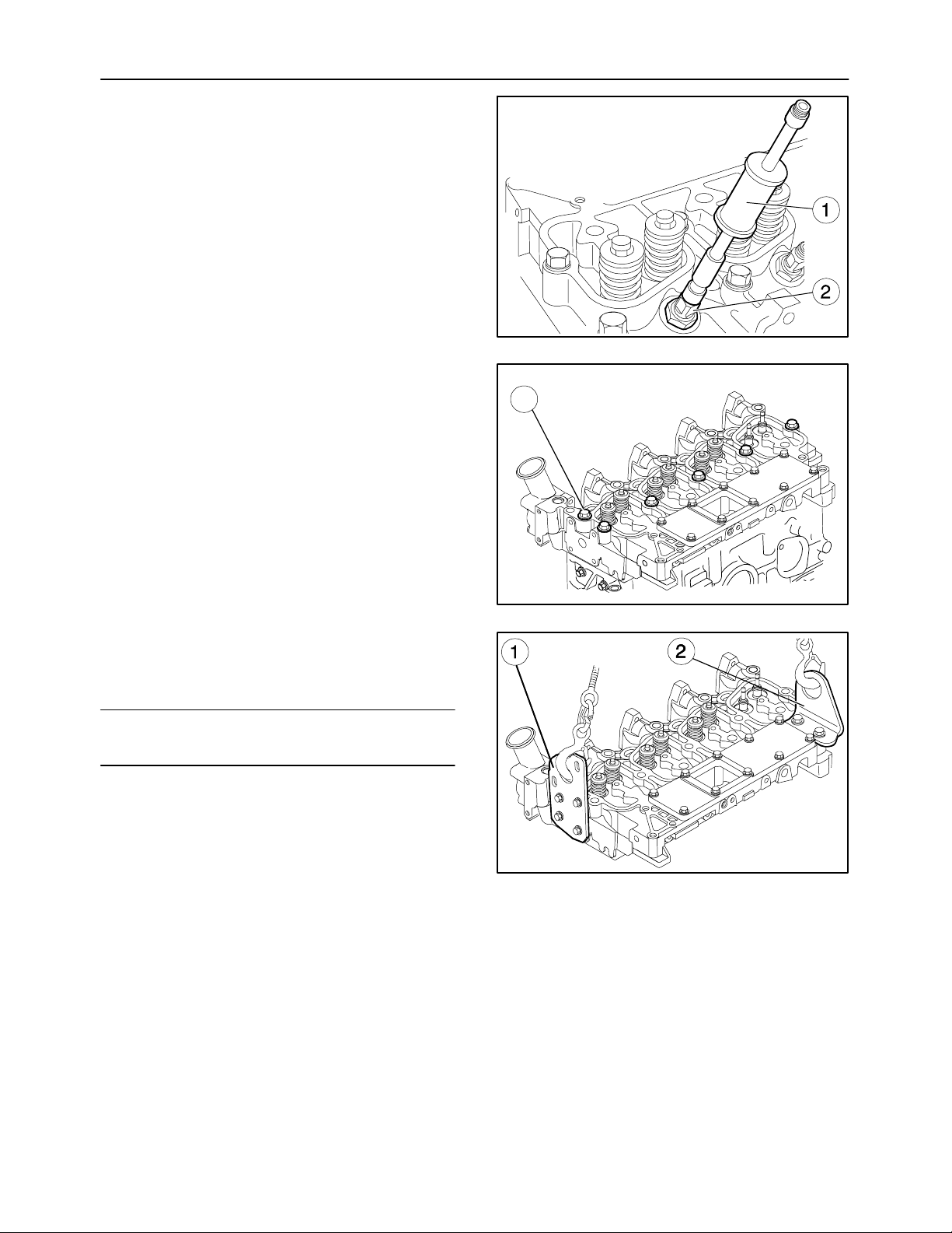
50. Extract the injectors (2) with tool 380000671 (1).
51. Take out the screws (1) fixing the head to the
crankcase.
MIF0934A
76
1
52. After fitting the brackets (1) and (2) hook the metal cables and detach the cylinder head from the
crankcase with the hoist.
NOTE: After removing the cylinder head, remove the
brackets (1) and (2).
MIF1120A
77
MIF1121A
78
Page 51
SECTION 10 -- ENGINE -- CHAPTER 1
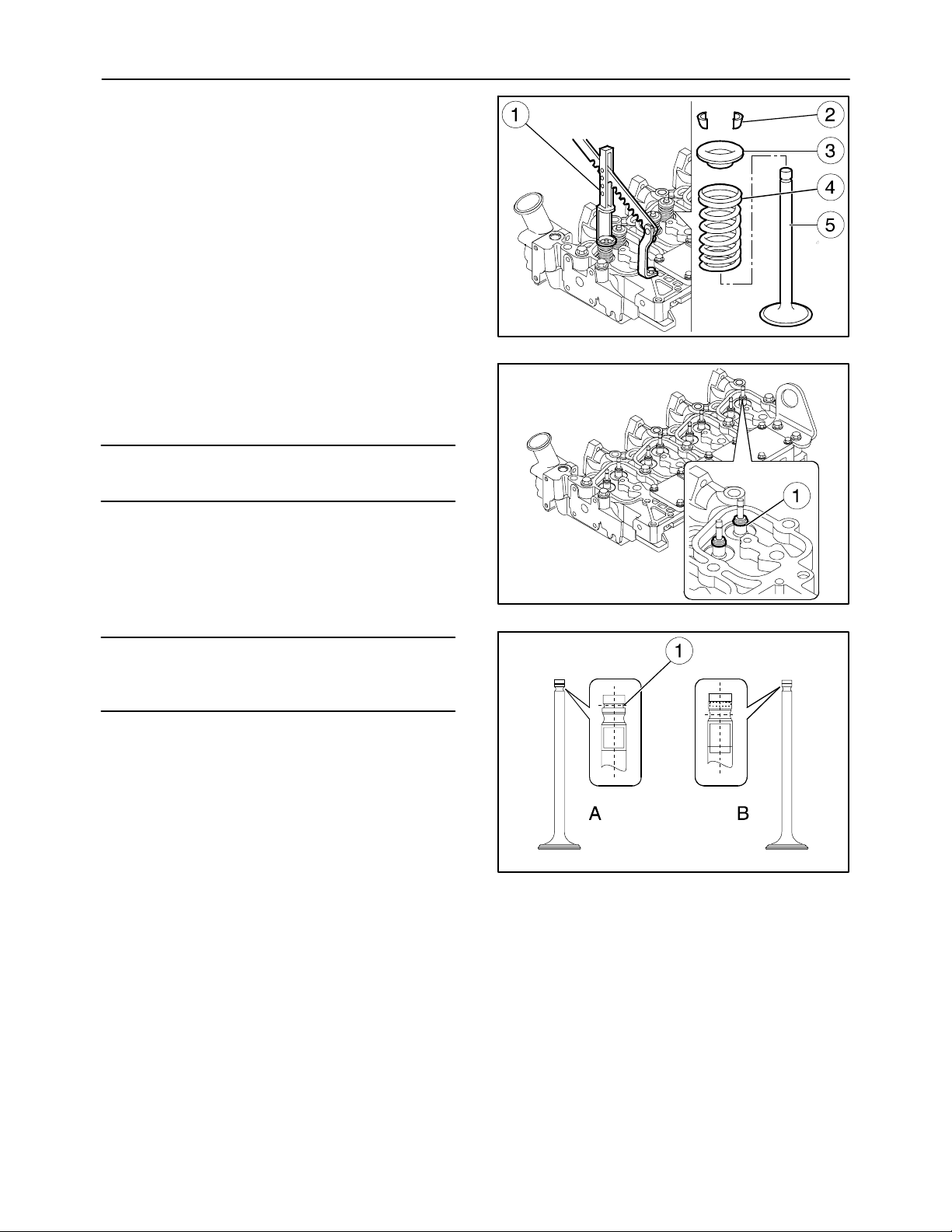
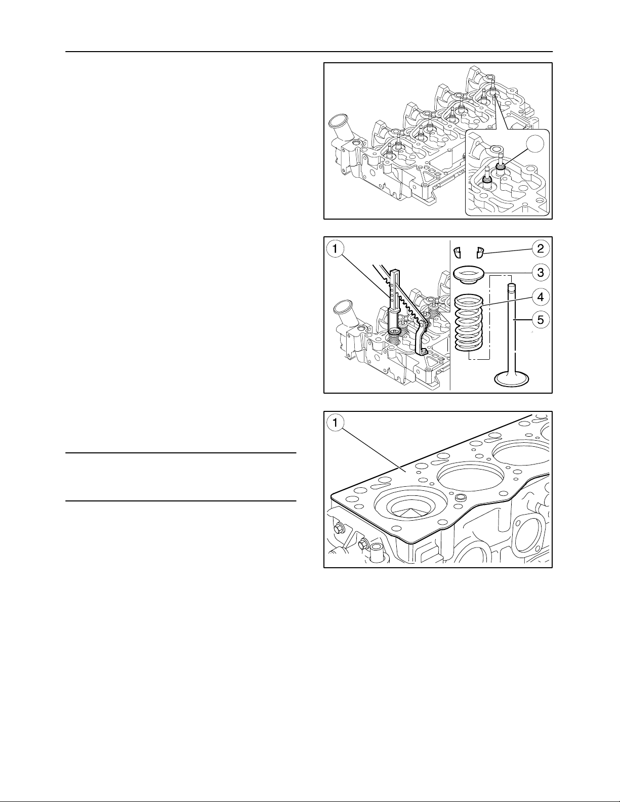
53. Valves are removed with tool 380000302 (1), applying pressure on the cap (3) so that, by compressing the springs (4), it is possible to remove
the cotters (2). Then remove the cap (3) and
springs (4).
Repeat this operation on all valves (5).
54. Remove the intake manifold cover and extract
the oil seals (1) fitted on the valve stems.
To remove the valves, turn the head over.
NOTE: Mark the inlet and exhaust valves before removing them.
51
MIF1122A
79
NOTE: The inlet valves differ from the exhaust
valves in the size of the head and there being an additional reference mark (1) on the stem.
A=Inlet valve.
B=Exhaust valve.
MIF1123A
80
MIF0948A
81
Page 52
52
SECTION 10 -- ENGINE -- CHAPTER 1
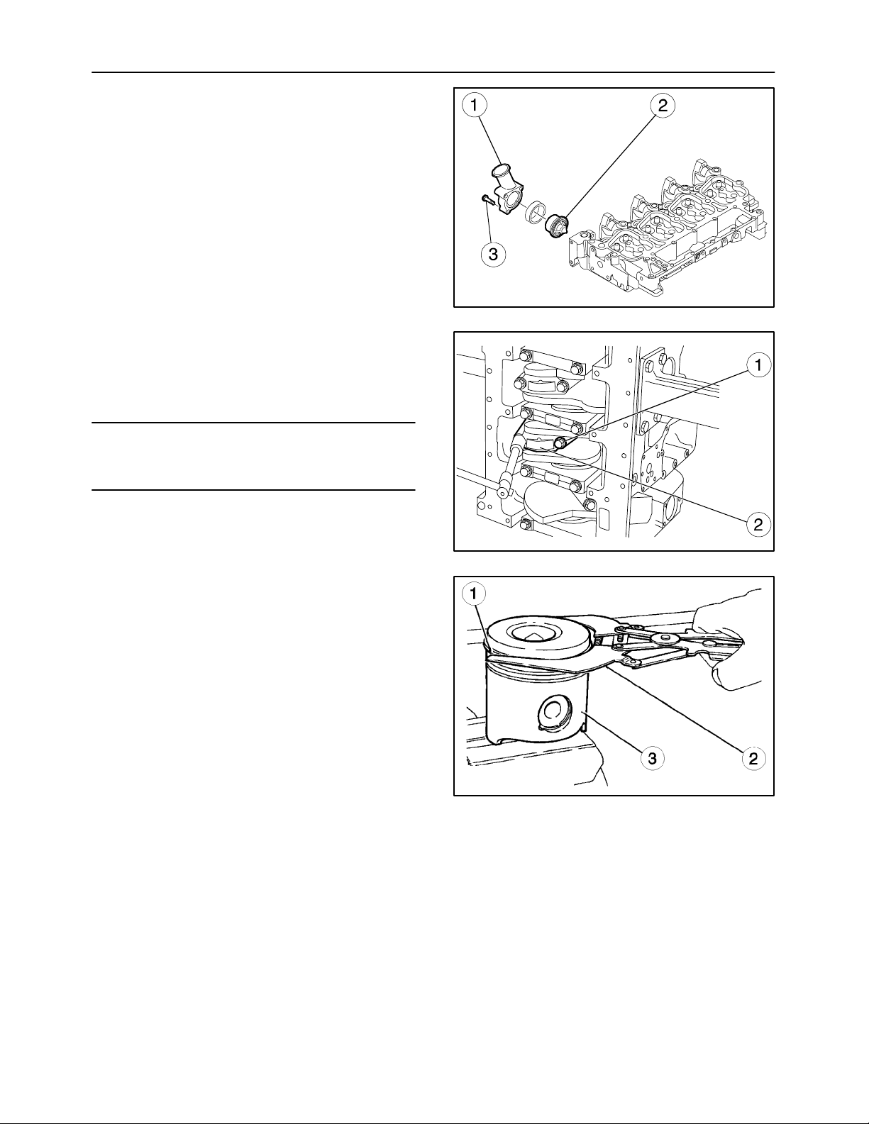
55. Remove the thermostat valve (2) from the governor body (1) taking out the screws (3).
56. Take out the screws (1) securing the connecting
rod caps (2) and remove them.
57. Extract the pistons together with the connecting
rods from the top of the crankcase.
NOTE: Keep the half bearings in their respective
housings since, if they are used, they must be
mounted in the position found upon disassembly.
MIF1124A
82
58. Remove the rings (1) from the piston (3) with the
pliers 380000221 (2).
MIF0938A
83
MIF0950A
84
Page 53
SECTION 10 -- ENGINE -- CHAPTER 1
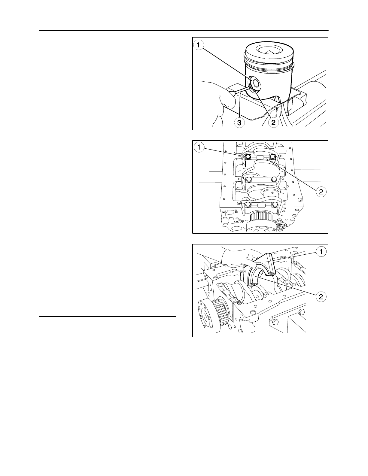
59. The piston pin (1) retaining rings (2) should be removed using a marking tool (3).
60. Take out the screws (1) and remove the main
bearing caps (2).
53
MIF0951A
85
61. The penultimate main bearing cap (1) and the related mounting have the half bearing (2)
equipped with a shoulder. Remove the pistons
with the connecting rods.
NOTE: Note down the assembly position of the top
and bottom half bearings since, if they are reused,
they must be mounted in the position found upon disassembly.
MIF1126A
86
MIF0940A
87
Page 54
54
SECTION 10 -- ENGINE -- CHAPTER 1
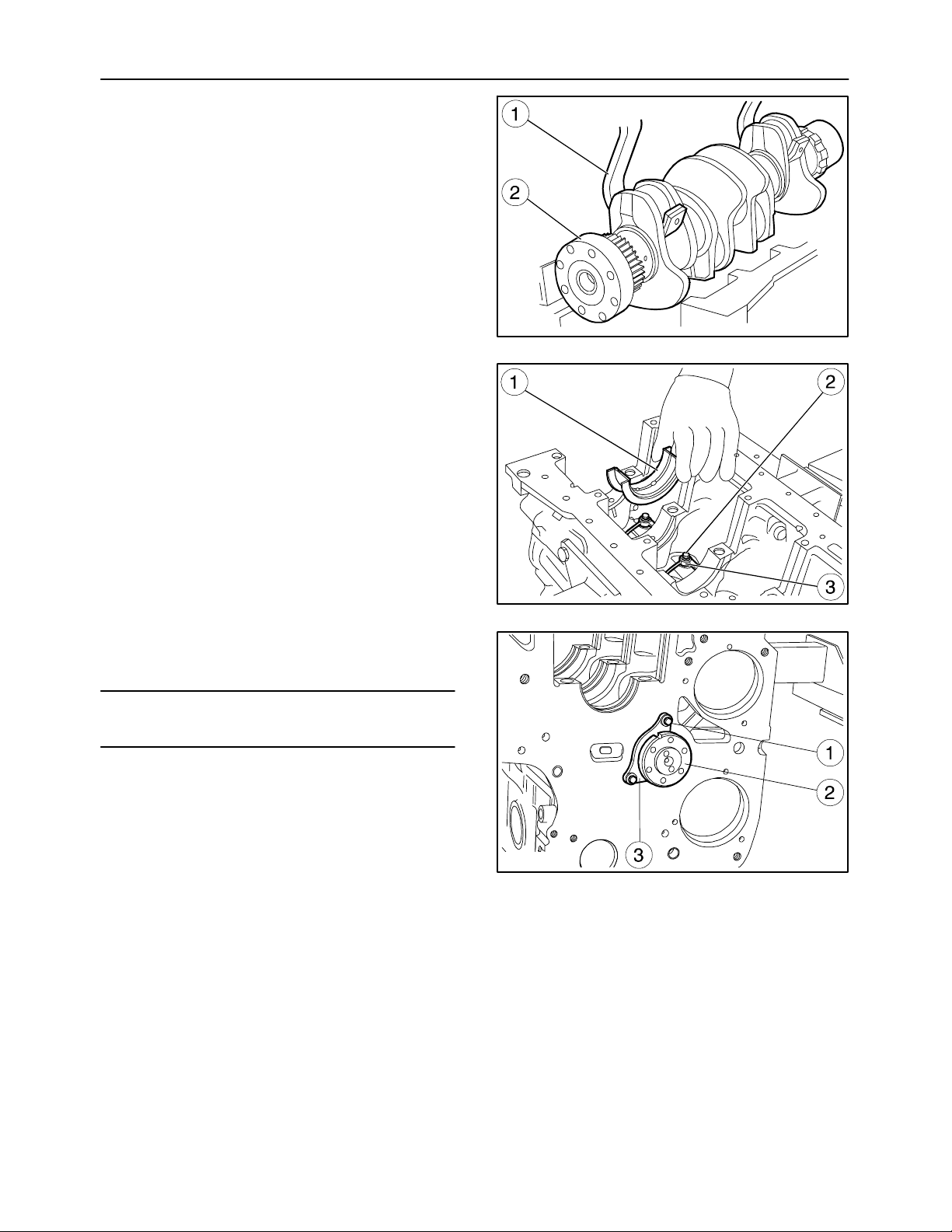
62. Using tool 380000362 (1) and a hoist, remove the
crankshaft (2) from the crankcase.
63. Remove the main half bearings (1).
64. Take out the screws (2) and remove the oil
nozzles (3).
MIF1127A
88
65. Take out the screws (1) and remove the plate (3)
retaining the camshaft (2).
NOTE: Note down the assembly position of the plate
(3).
MIF0942A
89
MIF1128A
90
Page 55
SECTION 10 -- ENGINE -- CHAPTER 1
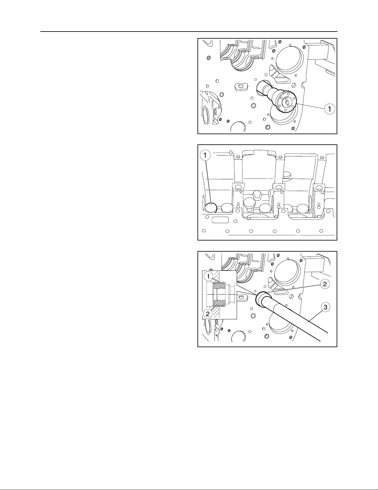
66. Carefully extract the camshaft (1) from the crankcase.
67. Extract the tappets (1) from the crankcase.
55
MIF1129A
91
68. To remove and renew the front and rear bushings
(1) of the camshaft, use the drift 380000667 (2)
and grip 380000668 (3).
MIF0945A
92
MIF1130A
93
Page 56
56
NOTE:
-- After disassembling the engine, thoroughly clean
the parts.
-- Pages (56--83) show the assembly operations
that require extra attention in order to assemble
parts correctly.
-- The torque settings are shown on pages 12 and
13.
IMPORTANT:
-- When partially or fully disassembling the engine,
all seals must be replaced.
-- Before inserting rotating parts and seals in seats,
lubricate the parts with engine oil.
-- When fitting the oil filter, lubricate the seal with
engine oil.
SECTION 10 -- ENGINE -- CHAPTER 1
CAUTION
Handle all parts carefully.
Do not put your hands or fingers between parts
and use appropriate tools to align fixing holes.
Wear the prescribed safety clothing, including
goggles, gloves and safety footwear.
ENGINE ASSEMBLY ON THE BENCH
Fitting the Bushings
(Disassembly operation 68.)
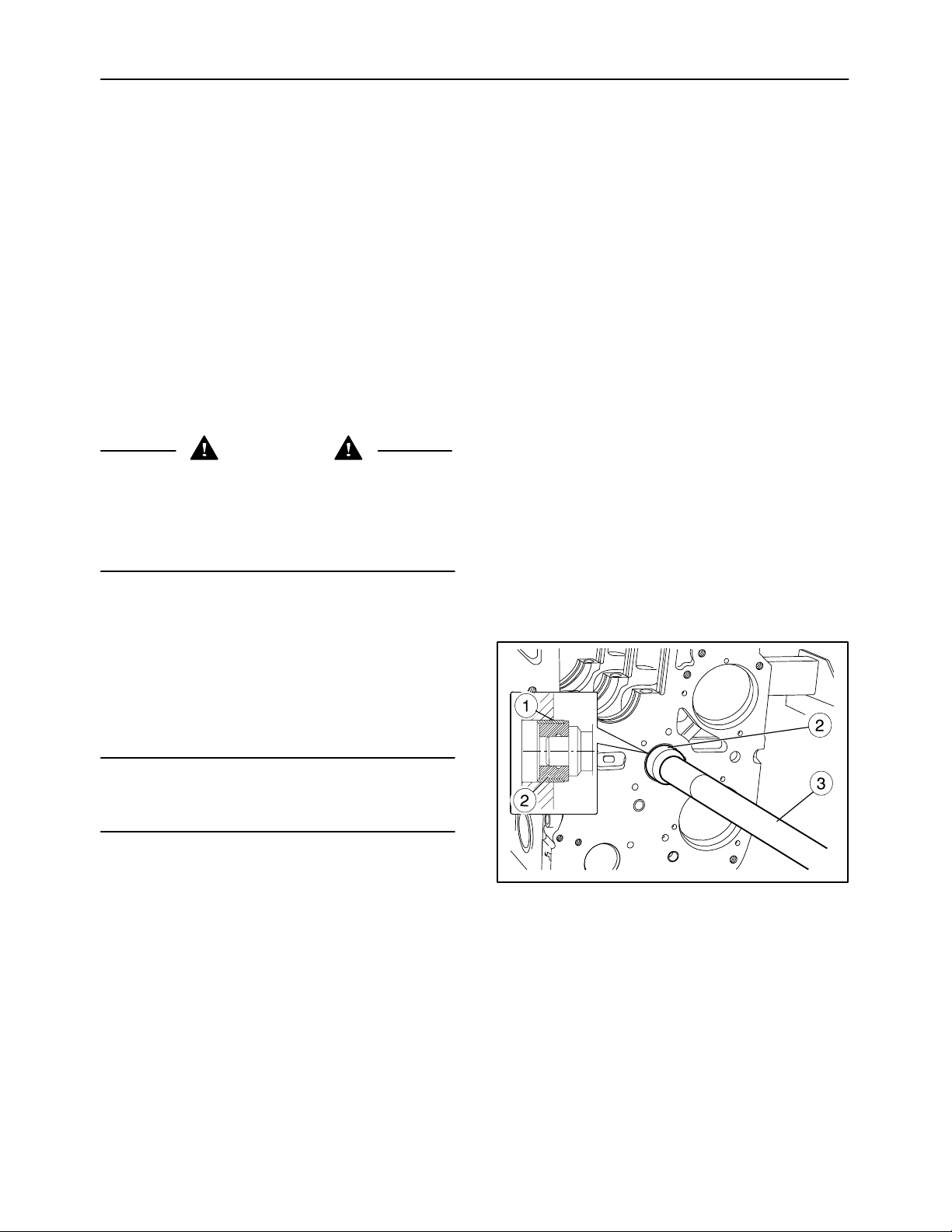
-- To remove and renew the front and rear bushings
(1) of the camshaft, use the drift 380000667 (2)
and grip 380000668 (3).
NOTE: The bushings (1) must be directed so that the
lubrication holes coincide with the holes in the seats
in the crankcase.
MIF1130A
94
Page 57
SECTION 10 -- ENGINE -- CHAPTER 1
Fitting the Tappets
(Disassembly operation 67.)
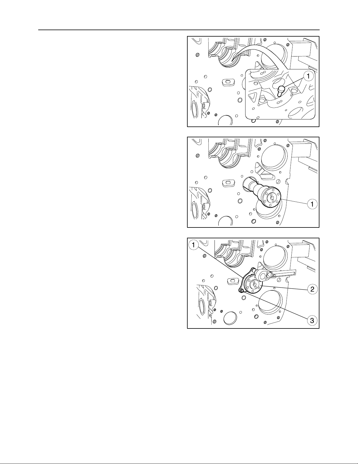
-- Lubricate the tappets (1) and fit them in their
seats in the crankcase.
Fitting the Camshaft
(Disassembly operation 65. to 66.)
-- Lubricate the bushings supporting the camshaft
and mount the camshaft (1) taking care that, during this process, the bushings or the supporting
seats do not get damaged.
57
MIF1131A
95
-- Position the plate (1) retaining the camshaft (2)
with the slot facing towards the top of the crankcase and the punchmark facing the operator.
Tighten the screws (3) to the prescribed torque
stated on page 12.
MIF1129A
96
MIF1132A
97
Page 58
58
SECTION 10 -- ENGINE -- CHAPTER 1
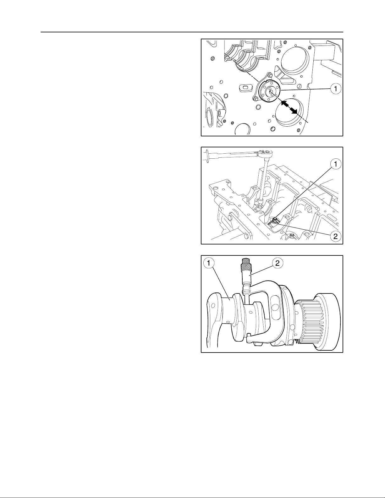
-- Check that the end float of the camshaft (1)
comes within the tolerance range prescribed on
page 10.
Fitting the Oil Nozzles
(Disassembly operation 64.)
-- Fit the nozzles (2) and tighten the retaining bolts
(1).
MIF1133A
98
Fitting the Crankshaft
(Disassembly operations 60. to 63.)
-- If any sign of seizure, scoring or too much ovality
is found on the main journals or crankpins, they
must be reground. Before reconditioning the pins
(1), use a micrometer (2) to measure the pins of
the shaft and according to the undersizes given
on page 8, define the diameter to which the pins
must be reduced.
MIF0957A
99
MIF0958A
100
Page 59
SECTION 10 -- ENGINE -- CHAPTER 1
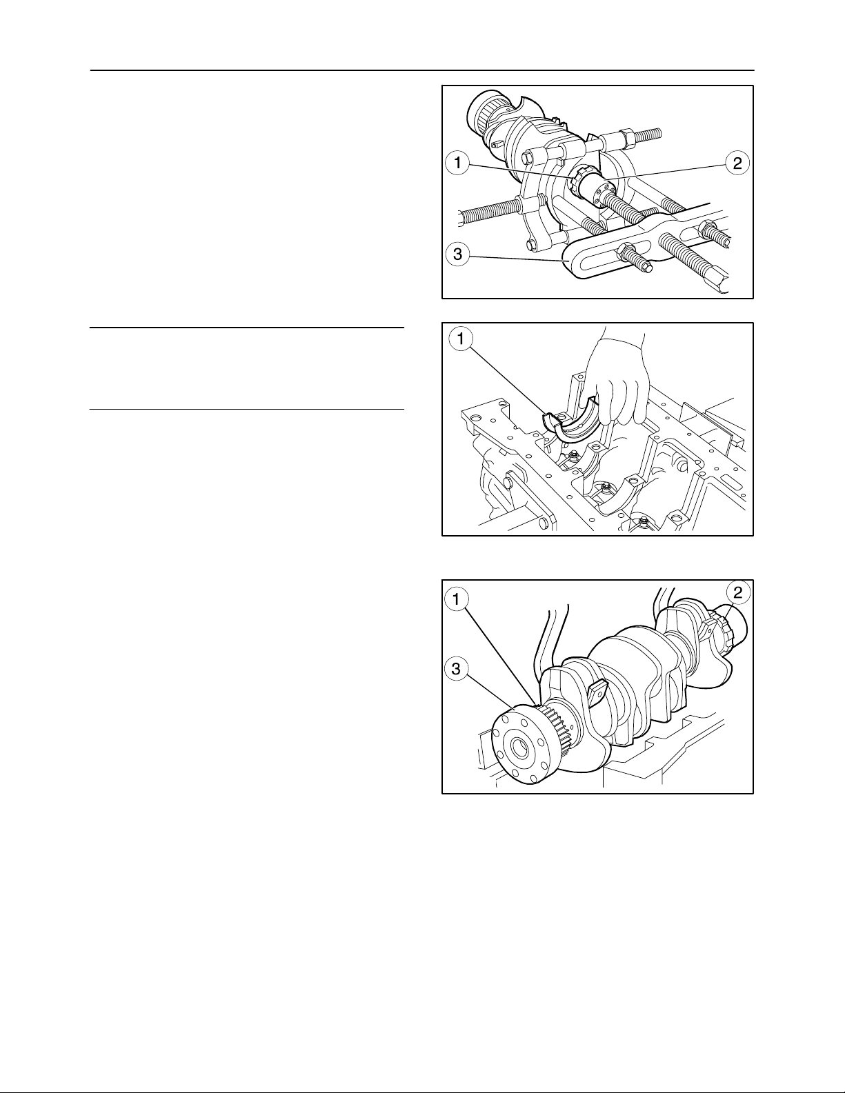
-- Check that the toothing of the grooved bushing
(1), splined onto the crankshaft (2) is neither
damaged nor worn; if it is, remove it with the a
suitable extractor (3).
-- When fitting the new grooved bushing it must be
heated for 60 minutes in an oven at a constant
temperature of 160 °C (320 °F) and spline it onto
the crankshaft.
NOTE: If the main journals of the crankshaft are undersized it is necessary to replace the main bearings
of the same undersize class made.
Do not modify the bearings in any way.
The main bearings (1) are supplied as spare parts
with an undersized inside diameter of 0.250--0.500
mm (0.0098--0.0196 in).
Carefully clean the main half bearings (1) with a lubrication hole and fit them into their respective seats.
The penultimate main half bearing (1) is equipped
with semi--circular thrust washers.
59
MIF1134A
101
MIF0962A
102
-- Fit the crankshaft (3) with the gear (1) and the
grooved bushing (2).
MIF1135A
103
Page 60
60
SECTION 10 -- ENGINE -- CHAPTER 1
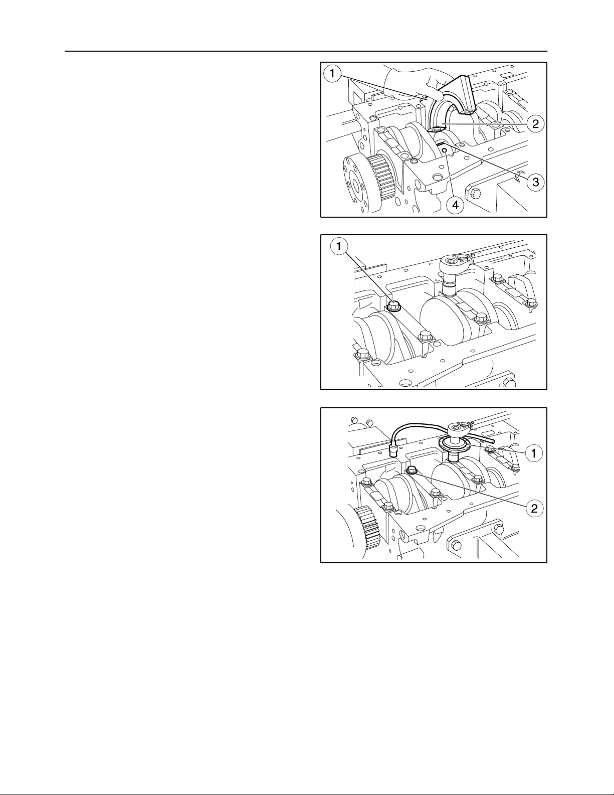
-- Check the clearance between the main journals
of the crankshaft and their respective bearings,
proceeding as follows:
-- Make sure that all parts are perfectly clean
and remove all traces of oil.
-- Position a length of calibrated wire (3) on the
crankshaft journals (4), parallel to the crankshaft centerline.
-- Fit the caps (1) complete with half bearings
(2) on the relevant supports.
-- Insert the pre--lubricated screws (1) and tighten
them in three successive stages.
st
and 2ndphase with a torque wrench to the
1
torque given on page 13.
MIF0964A
104
rd
-- 3
phase with tool 380000304 (1) positioned as
in the figure, further tighten the screws (2) with an
angle of 90°±5°.
MIF0965A
105
MIF0966A
106
Page 61
SECTION 10 -- ENGINE -- CHAPTER 1
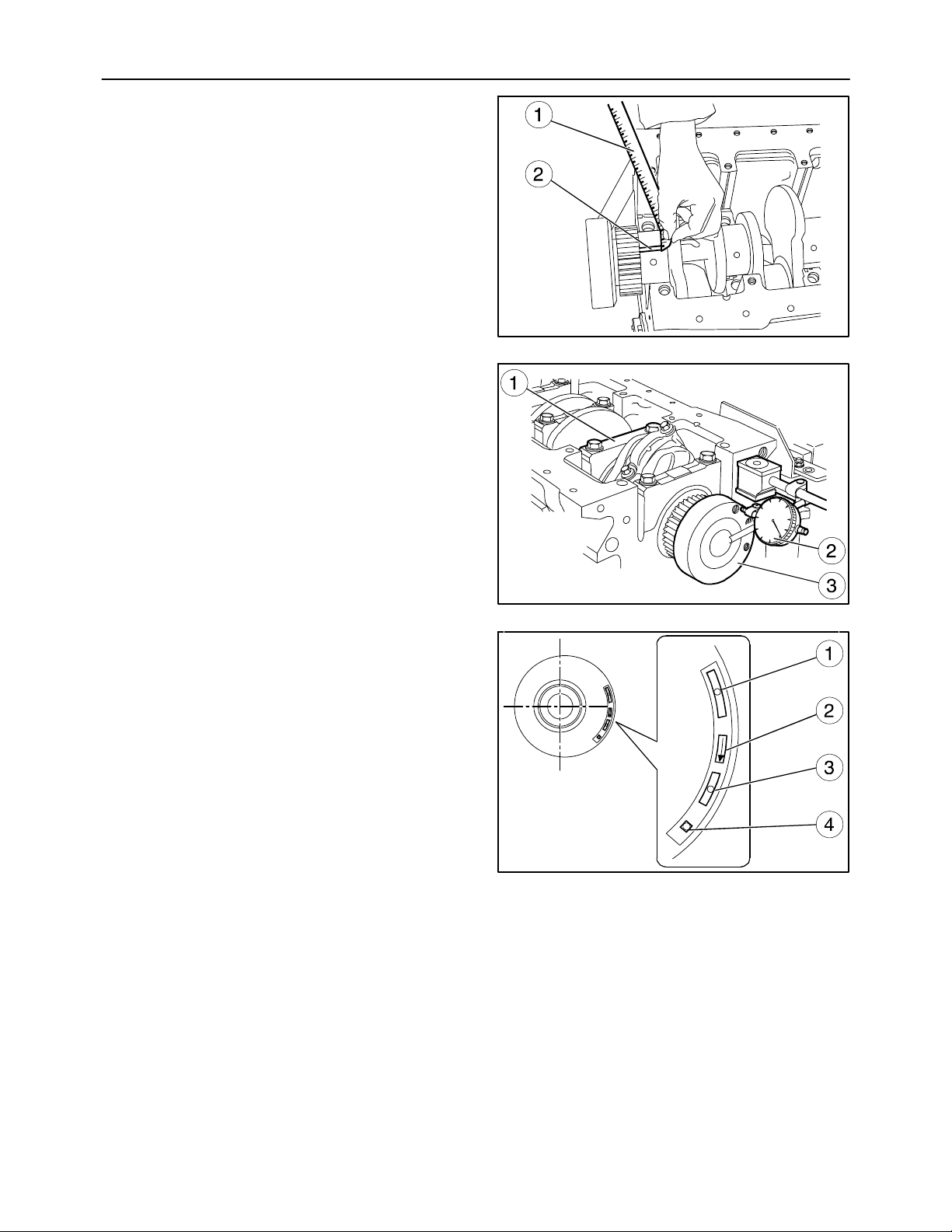
-- Remove the support caps.
The clearance between the main bearings and the
relevant journals is measured by comparing the
width of the calibrated wire (2), at the point of greatest
crushing, with the graduation of the scale on the case
(1) containing the calibrated wire.
The numbers shown on the scale indicate the mating
clearance in millimeters.
Check that the clearance is the one prescribed on
page 8, then lubricate the main bearings and permanently mount the supports, tightening the retaining
bolts as described above.
The crankshaft assembly end float is checked by setting a dial gauge (2) with a magnetic base on the
crankshaft (3) as shown in the figure, the normal assembly clearance must come within the tolerance
prescribed on page 8.
If the clearance is found to be any greater, change the
main half bearings of the penultimate rear thrust bearing support (1) and check the clearance again between
the crankshaft journals and main half bearings.
61
MIF1075A
107
Fitting the Connecting Rod -- Piston Assembly
(Disassembly operations 58. to 59.)
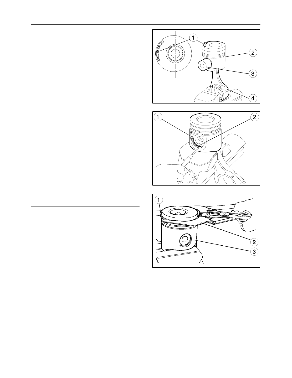
The following references are cut into the crown of the
piston:
-- Spare part number and design modification number;
-- Arrow showing the direction of assembly of the
piston in the cylinder liner, it must face the front
of the crankcase (auxiliary member side).
-- Date of manufacture.
st
-- Stamping indicating testing of the 1
groove in-
sert.
MIF1076A
108
MIF0967A
109
Page 62
62
SECTION 10 -- ENGINE -- CHAPTER 1
1. Using the pin (3) connect the piston (2) to the
connecting rod (4) so that the reference arrow (1)
for fitting the piston (2) in the cylinder liner is facing as described in point 2.
2. Insert the rings (2) retaining the pin (1).
MIF0968A
110
3. To fit the rings (1) on the piston (3) use tool
380000221 (2).
NOTE: Thepistonrings(seepage8to9)aresupplied as spare parts in the following sizes:
-- standard, marked with yellow paint;
-- oversized by 0.5 mm (0.0196 in) and marked with
yellow/green paint;
MIF1060A
111
MIF0969A
112
Page 63
SECTION 10 -- ENGINE -- CHAPTER 1
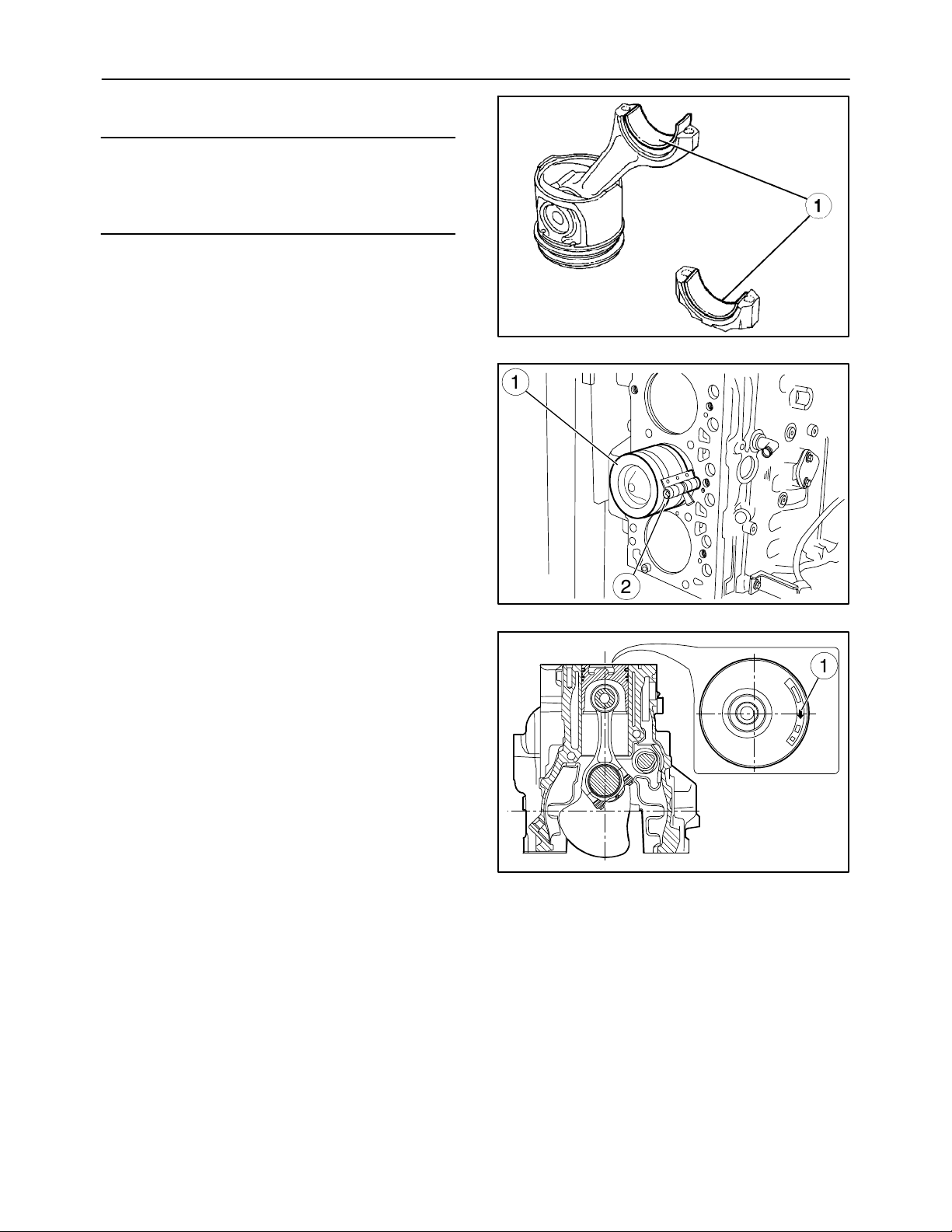
4. Fit the half bearings (1) on the connecting rod
and cap.
NOTE: If the crankpins of the crankshaft are undersized it is necessary to replace the big end bearings
of the same undersize class made.
Do not modify the half bearings in any way.
Fitting the Piston Connecting Rod Assemblies in the Cylinder Liners
(Disassembly operation 57.)
1. Lubricate the pistons well, including the piston
rings and the inside of the cylinder liners.
2. With the aid of the ring clamp 380000220 (2), fit
the connecting rod--piston assemblies (1) in the
cylinder liners.
63
MIF0970A
113
3. The ring openings must be staggered apart by
120°;
4. The connecting rod/piston assemblies must all
have the same weight;
5. The arrow (1) stamped on the crown of the pistons must face the auxiliary member side of the
engine and the recess in the piston skirt must correspond to the position of the oil nozzles.
MIF0971A
114
MIF0972A
115
Page 64
64
SECTION 10 -- ENGINE -- CHAPTER 1
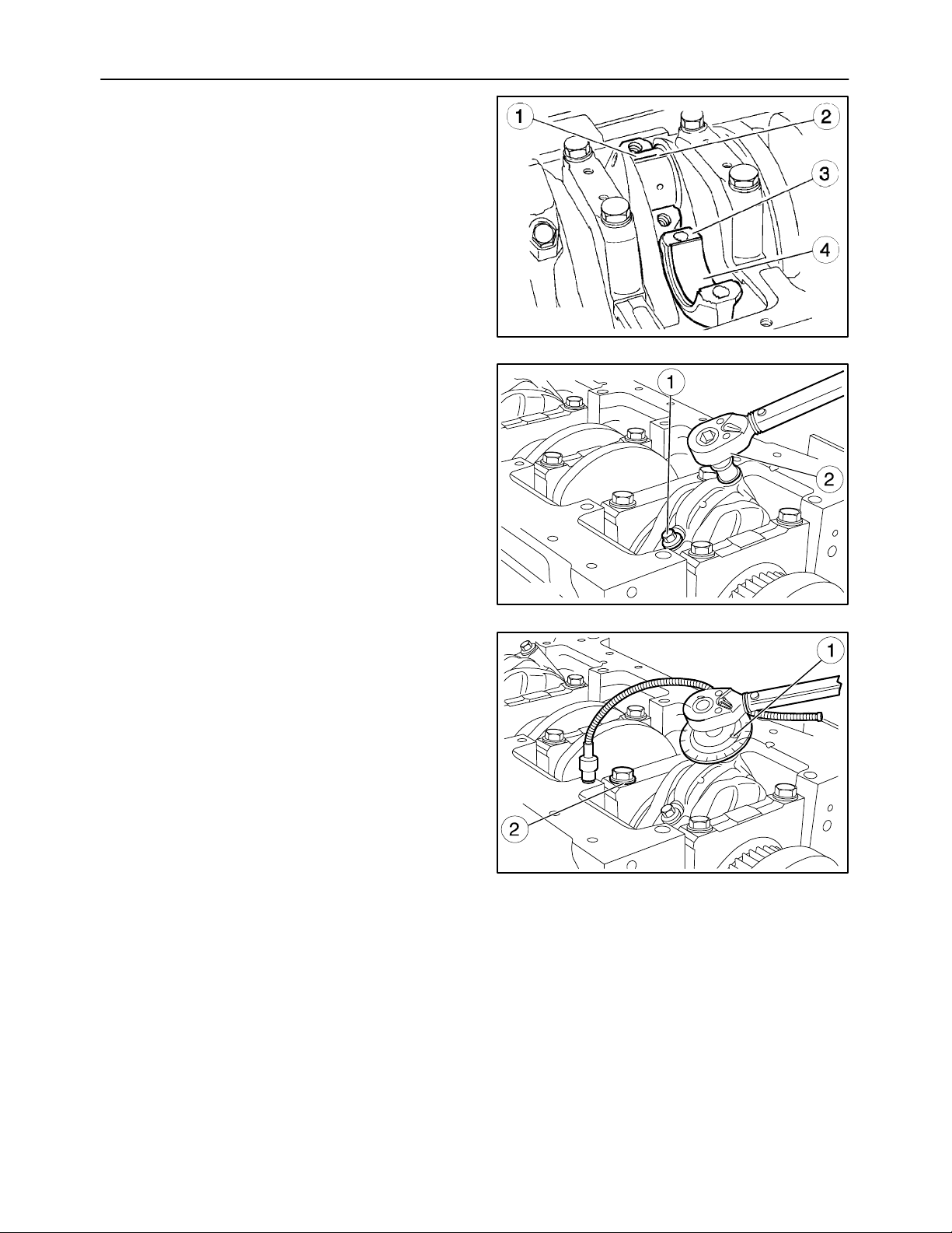
To measure the clearance proceed as follows:
-- Carefully clean the parts and remove all traces of
oil;
-- Position a length of calibrated wire (2) on the
crankshaft journals (1);
-- Fit the connecting rod caps (3) with the relevant
half bearings (4).
Big End Cap Assembly
(Disassembly operation 56.)
1. Tighten the screws (1) previously lubricated with
engine oil with a torque wrench (2) to the torque
prescribed on page 13.
MIF1077A
116
2. Fit tool 380000304 (1) on the socket wrench and
further tighten the bolts (2) as prescribed on
page 13.
MIF0973A
117
MIF0974A
118
Page 65
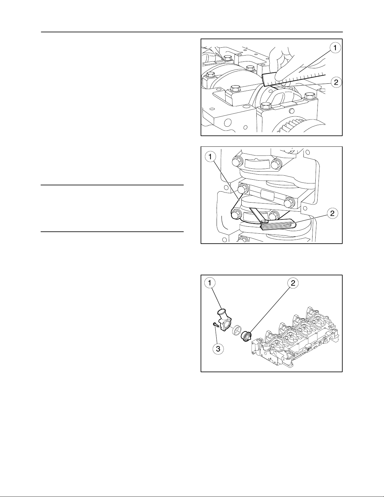
SECTION 10 -- ENGINE -- CHAPTER 1
3. Remove the cap and determine the clearance by
comparing the width of the calibrated wire (2)
against the graduated scale printed on the packet (1) containing the wire.
4. Check that the clearance is the one prescribed
on page 8, then lubricate the big end half bearings and permanently mount them, tightening the
connecting rod cap retaining bolts as described
on page 13.
NOTE: Before permanently fitting the connecting rod
cap retaining bolts, check that their diameter, measured at the center of the length of the thread, is no
less than 0.1 mm (0.0039 in) of the diameter measured at approximately 10 mm (0.3937 in) from the
end of the bolt.
65
MIF1078A
119
5. Check by hand that the connecting rods (1) run
axially on the crankshaft journals and their end
float measured with a feeler gauge (2) is as prescribed on page 9.
Fitting the Thermostat Valve
(Disassembly operation 55.)
1. Assemble the thermostat valve (2) to its associated body (1) with the screws (3).
MIF1079A
120
MIF1124A
121
Page 66
66
SECTION 10 -- ENGINE -- CHAPTER 1
Fitting the Cylinder Head
(Disassembly operations 51. to 54.)
1. Lubricate the valve stem and insert into the relevant valve--guides according to the position
marked during disassembly.
2. Fit the seals (1).
3. Position the following parts on the cylinder head:
spring (4) and top cap (3): using tool 380000302
(1) compress the spring (4) and retain the parts
to the valve (5) with the cotters (2).
1
MIF1137A
122
4. Check that the mating surfaces (1) of the cylinder
head and crankcase are clean.
5. Do not dirty the cylinder head gasket.
NOTE: Before reusing the cylinder head retaining
bolts, check they show no sign of deterioration or deformation and replace them if they do.
MIF1138A
123
MIF1009A
124
Page 67
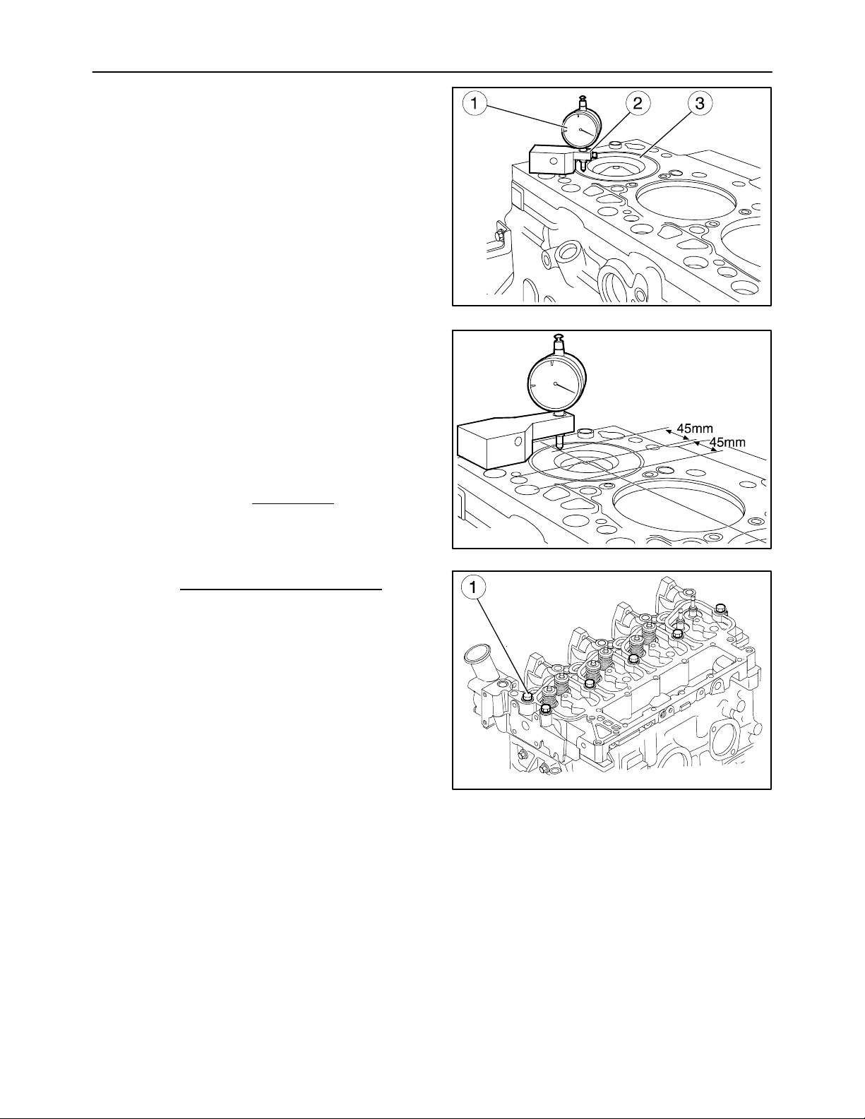
SECTION 10 -- ENGINE -- CHAPTER 1
S
S
6. Using the dial gauge 380000364 (1) fitted with its
base 380000228 (2), check the protrusion of the
pistons (3) at T.D.C. from the cylinder block face is
within the tolerance limits prescribed on page 9.
7. Since there are two type of head gasket, to choose
its thickness 1.25 mm (0.0492 in) Type A and 1.15
mm (0.0452 in) Type B) make the following measurements:
-- for each piston, as shown in the figure, at a distance of 45 mm (1.7716 in) from the center of the
piston, measure its protrusions S1 and S2 from
the top face of the crankcase and then calculate
the mean:
S1 + S2
=
cyl1
2
67
MIF1080A
125
Repeat this operation for pistons 2, 3 and 4 and
calculate the mean value:
S
cyl1+Scyl2+Scyl3+Scyl4
=
4
If S is > 0.40 mm (0.0157 in) use the gasket
type A.
If S is < 0.40 mm (0.0157 in) use the gasket
type B.
8. Fit the lifting brackets to the cylinder head.
9. Install the gasket, fit the cylinder head on the
crankcase, screwing down the screws (1) without tightening them to torque.
MIF1086A
126
MIF1139A
127
Page 68

68
SECTION 10 -- ENGINE -- CHAPTER 1
10. Before inserting the control rods, check that the
spherical seat (1) of contact with the rocker arm
adjuster screw and the spherical end (2) of contact with the tappet show no sign of wear; if there
are, then change them. The inlet and exhaust
valve control rods are identical and can therefore
be interchanged.
-- Spread LOCTITE 5999 sealant between the cover (2) and the manifold (3) and tighten the screws
(1) to the torque prescribed on page 12.
MIF1011A
128
Fitting the Injectors
(Disassembly operation 50.)
1. On the injector (1), mount a new seal (2) lubricated with Vaseline and a new washer (3).
2. Fit the injectors 2, 3, 4 in the seats on the cylinder
head and tighten them to the torque prescribed
on page 12.
MIF1094A
129
MIF1063A
130
Page 69
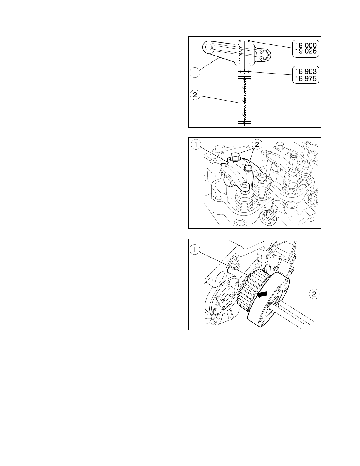
SECTION 10 -- ENGINE -- CHAPTER 1
Fitting the Rocker Arm Assembly
(Disassembly operation 49.)
1. Check that the spindle (2) / rocker arm (1) coupling surfaces are neither too worn nor damaged.
Main spindle--rocker arm data (mm)
2. Check that the tappet adjusters are unscrewed to
prevent them sticking on the rods when fitting the
rocker arm assembly (1).
3. Then mount the rocker arm assembly comprising
the support and spindles and secure them to the
head without tightening the bolts (2) to torque.
They will be tightened to torque together with
those fixing the cylinder head.
69
.
.
.
.
MIF1012A
131
Fitting the Timing Gear
(Disassembly operation 47.)
1. Use a marker pen to mark the tooth of the driving
gear (1) mounted on the crankshaft (2) on the
side of which the reference mark (→) is stamped
for timing.
MIF1013A
132
MIF0977A
133
Page 70
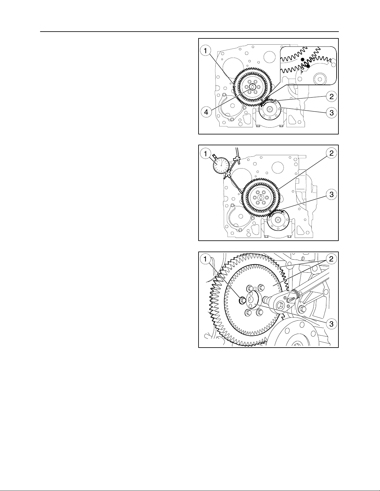
70
SECTION 10 -- ENGINE -- CHAPTER 1
2. Direct the crankshaft (3) and camshaft (4) so that
when mounting the driven gear (1) on the camshaft, the marks stamped on the gears (1 and 2)
coincide.
3. Place the dial gauge (1) on the timing gear (2)
and check that the clearance between the gears
(2) and (3) is between 0.076 to 0.280 mm (0.0029
to 0.0110 in).
MIF0978A
134
4. Insert the screws (1) fixing the gears (2) to the
camshaft (3) and tighten them to the torque prescribed on page 12.
MIF1140A
135
MIF1141A
136
Page 71
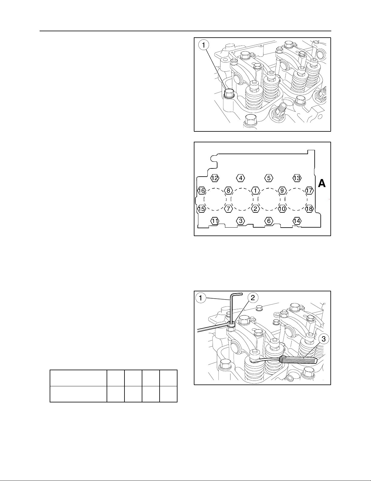
SECTION 10 -- ENGINE -- CHAPTER 1
5. Tighten the cylinder head fixing screws in the
sequence shown in Figure 138.
-- Tightening sequence for cylinder head
bolts:
st
- 1
wrench:
M 12 x 1.75 x 70 bolt: 50 N⋅m ± 5N⋅m
(ref. 3--6--11--14) (37 ± 4 ft-lbs)
M 12 x 1.75 x 140 bolt: 40 N⋅m ± 5N⋅m
(ref. 1--2--7--8--9-- 10-- (30 ± 4 ft-lbs)
15--16--17--18)
stage of tightening with a torque
71
MIF1014A
137
M 12 x 1.75 x 180 bolt: 70 N⋅m ± 5N⋅m
(ref. 4--5--12--13) (52 ± 4 ft-lbs)
nd
- 2
stage tightening to an angle of 90°
for all the screws
- 3
rd
stage additional tightening to an
angle of 90° for 140 and 180 mm (5.5118 and
7.0866 in) long bolts only.
A = fan side
6. Adjust the clearance between the rocker arms
and valves using an Allen wrench (1), box
wrench (2) and feeler gauge (3).
The working clearance is given on page 10.
7. Move the cylinder to the exhaust stroke and measure the clearance; the valves in the cylinder are
closed, whilst those on the symmetrical cylinder
are rocking.
The symmetrical cylinders are 1 -- 4 and 3 -- 2.
-- FIRING ORDER 1 -- 3 -- 4 -- 2
Balance valves
of cylinder no.
Adjust valve clearance of cylinder no.
1 3 4 2
4 2 1 3
MIF1015A
138
MIF1016A
139
Page 72
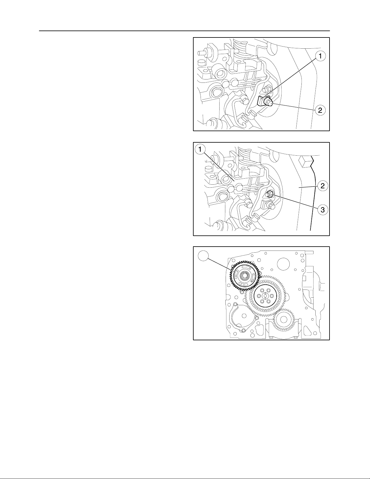
72
SECTION 10 -- ENGINE -- CHAPTER 1
Fitting the Injection Pump
(Disassembly operations 38.)
1. Before fitting the injection pump, check that the
engine flywheel is still locked and in time with cylinder no. 1 at T.D.C. (as described in operation 37.), using tools 380000988 and
380000732.
2. Do the timing for the injection pump (1, fig. 141)
in relation to the drive gear, proceeding as described on page 101.
3. Then loosen bolt (2), insert the “L” spacer (1) and
lock bolt (2) to make the fuel pump spindle free
to turn.
4. Fix the injection pump casing (1) to the seat of the
gear box (2) with the screws (3).
MIF0920A
140
5. Spline the gear (1) transmitting drive to the pump.
MIF0981A
141
1
MIF0982A
142
Page 73
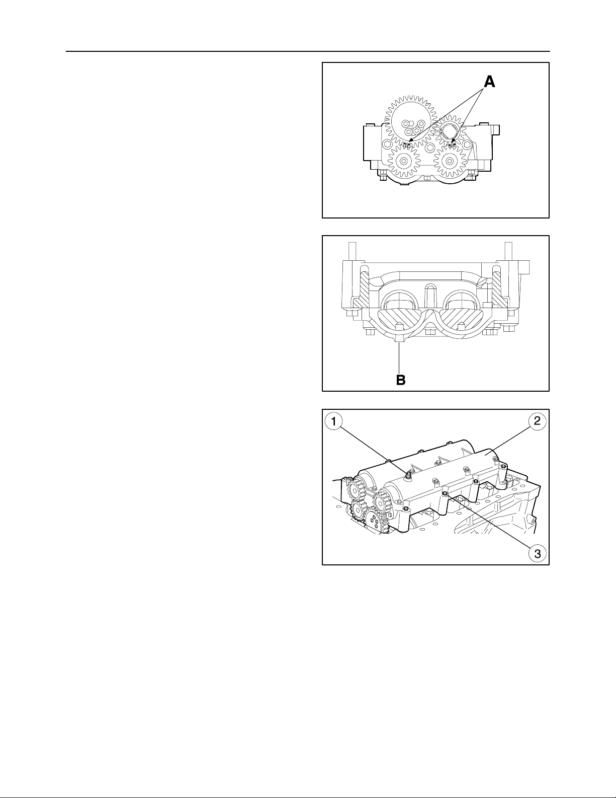
SECTION 10 -- ENGINE -- CHAPTER 1
Fitting the Additional Counterweights
(Disassembly operations 36.)
1. After taking the first cylinder to the top dead center and doing the timing of the gear of the timing
system as described above, do the timing of the
additional counterweights, making the marks (A)
stamped on the gears coincide as shown in the
figure.
2. Insert the retaining pin in the hole (B) on the additional counterweight assembly to block rotation
during the subsequent installation phase.
73
MIF1142A
143
3. Fit the additional counterweights (2), tighten the
screws (3) to the torque prescribed on page 12
and remove the retaining pin (1) from the hole
(B).
MIF1143A
144
MIF1113A
145
Page 74
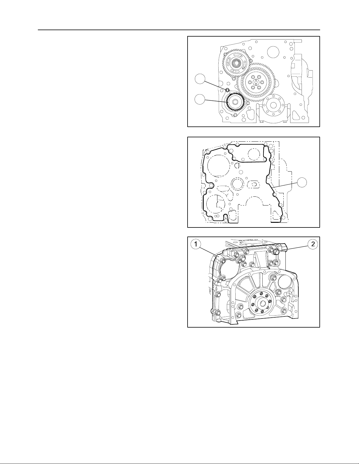
74
Fitting the Hydraulic Pump Drive Gear
(Disassembly operation 48.)
1. Insert the gear driving the hydraulic pumps (2)
into the seat.
2. Tighten the bolts (1).
Fitting the Timing Gear Casing
(Disassembly operation 46.)
1. Carefully clean the timing gear box (1) and the
crankcase.
Cleaning the surface to seal is both necessary
and unavoidable in order to obtain an effective
seal. Apply LOCTITE 5999 sealant onto the box
to form a bead with a diameter of a few mm as
shown in fig. 147. It must be uniform (no lumps),
with no air bubbles, thin areas or breaks.
Any flaws must be corrected in as short a time as
possible.
Avoid using excess material to seal the joint.
Too much sealant would tend to come out on both
sides of the joint and clog the lubricant passageways.
After applying the sealant, the joints require immediate assembly (10 -- 20 minutes).
2. Refit the box (1) to the crankcase.
3. Tighten the retaining bolts (2) in the position
found during disassembly.
SECTION 10 -- ENGINE -- CHAPTER 1
1
2
MIF1144A
146
1
MIF1136A
147
MIF1147A
148
Page 75
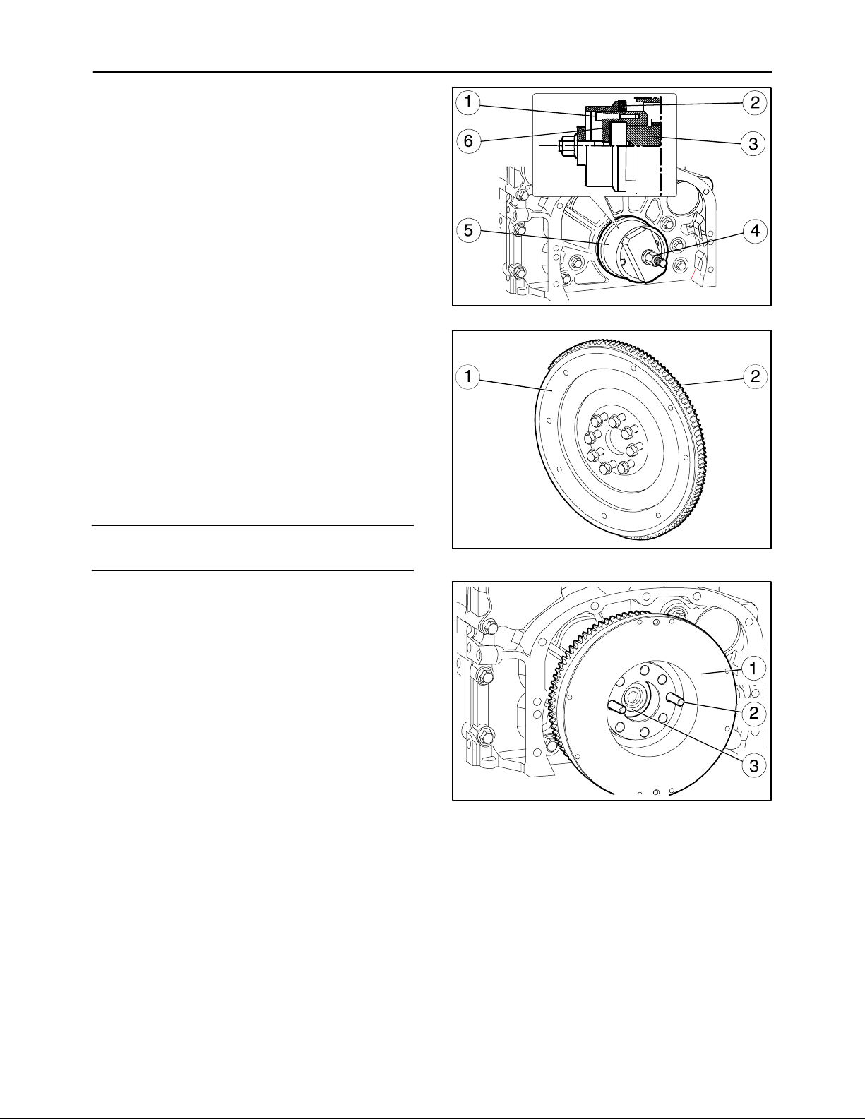
SECTION 10 -- ENGINE -- CHAPTER 1
Fitting the Crankshaft Rear Seal
(Disassembly operations 42. to 45.)
1. Fit part (6) of tool 380000664 on the rear shank
(3) of the crankshaft. Secure it with the screws (1)
and spline the new seal (2) onto it.
2. Position part (5) on part (6), screw down the nut
(4) until the seal (2) is completely fitted in the flywheel casing.
Fitting the Flywheel
(Disassembly operations 39. to 41.)
1. Check the clutch plate mating surface; turning is
required if there is any scoring.
2. Check the state of the teeth of the crown gear (2).
If you find any breakage or excessively worn
teeth, replace it. Mount the new one, previously
heated to a temperature of 150 °C for 15 to
20 min.
75
MIF1145A
149
NOTE: The nominal thickness of the engine flywheel
is 70.5 mm (2.7755 in).
3. Screw two pins (2) of the appropriate length into
the holes in the shaft (3) and, using the sling,
mount the engine flywheel (1).
MIF0990A
150
MIF1116A
151
Page 76
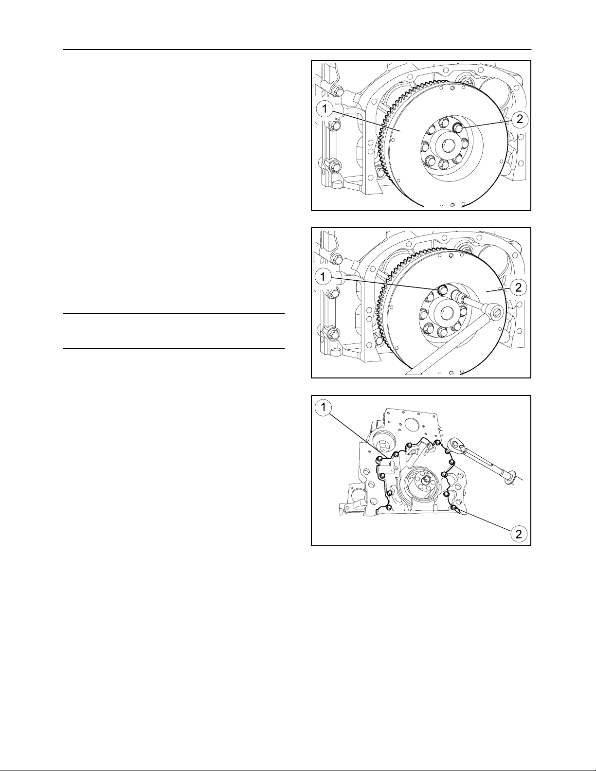
76
SECTION 10 -- ENGINE -- CHAPTER 1
4. Spline the flywheel (1) onto the crankshaft, tightening the screws (2) by hand.
5. Lock the flywheel appropriately before tightening
the relevant screws to torque.
6. Tighten the bolts (1) securing the engine flywheel
(2) in two stages as described on page 13:
- 1
st
phase, tightening with torque
wrench to a torque of 30 ± 5Nm;
nd
- 2
phase, tightening to an angle of 60°
± 5°.
MIF1115A
152
NOTE: Tightening to an angle is done with tool
380000304.
Fitting the Oil Pump
(Disassembly operation 35.)
1. Insert the seal.
2. Fit the oil pump (1).
3. Insert the tightening screws (2) and tighten them
to the torque prescribed on page 12.
MIF1146A
153
MIF1149A
154
Page 77
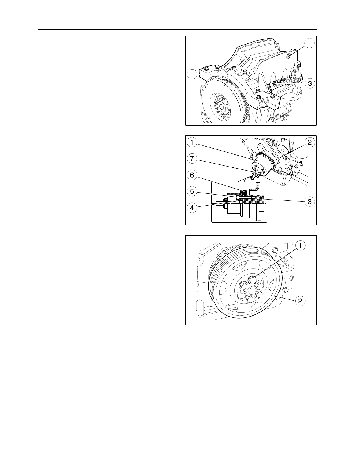
SECTION 10 -- ENGINE -- CHAPTER 1
77
Fitting the Oil Sump
(Disassembly operation 34.)
1. Place the new seal on the crankcase.
2. Fit the oil sump (1).
3. Insert the screws (3) and tighten them to the
torque prescribed on page 12.
4. Tighten the drain plugs (2) to the torque prescribed on page 12.
Fitting the Crankshaft Front Seal
(Disassembly operations 29. to 33.)
1. Fit part (4) of tool 380000666 on the front shank
(3) of the crankshaft.
2. Secure it with the screws (5) and spline the new
seal (6) onto it.
3. Position part (1) on part (4), screw down the nut
(7) until the seal (6) is completely fitted in the front
cover (2).
2
1
MIF1117A
155
Fitting the Crankshaft Front Pulley
(Disassembly operation 28.)
1. Spline the pulley (2) onto the crankshaft.
2. Tighten the screws (1) to torque and angle (see
page 13), using tool 380000304.
MIF1001A
156
MI F 1111A
157
Page 78
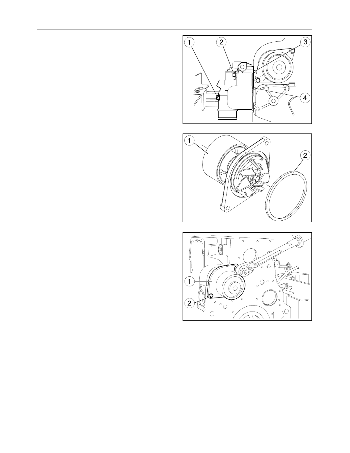
78
SECTION 10 -- ENGINE -- CHAPTER 1
Fitting the Cooling System Union
(Assembly operation 27.)
1. Position the cooling system fitting so that the pins
(3 and 4) are against the crankcase.
2. Tighten the screws (1 and 2).
Fitting the Coolant Pump
(Assembly operation 26.)
1. Fit a new seal (2) onto the coolant pump (1).
MIF1005A
158
2. Mount the coolant pump (1).
3. Screw down the screws (2) and tighten them to
the torque prescribed on page 12.
MIF0997A
159
MIF1150A
160
Page 79
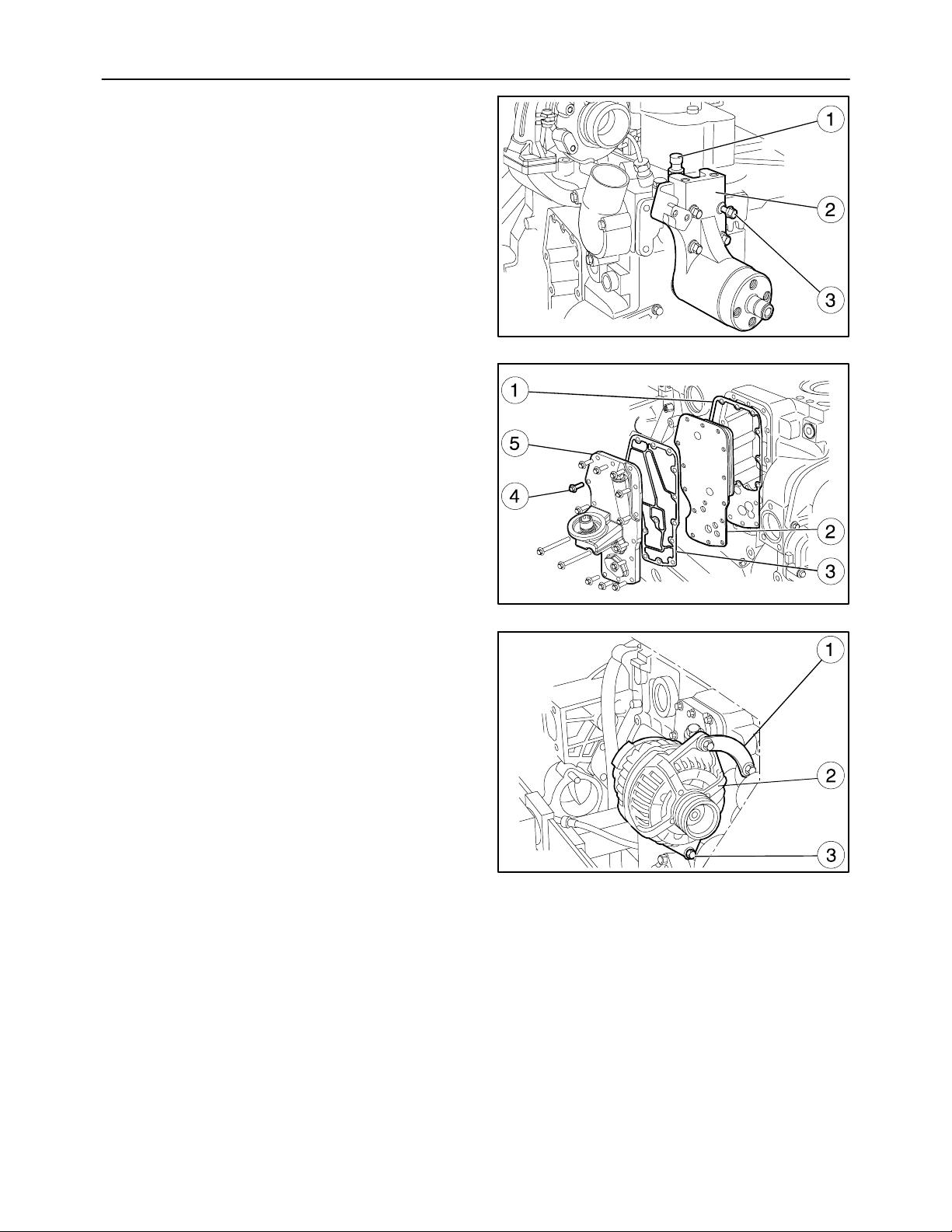
SECTION 10 -- ENGINE -- CHAPTER 1
Fitting the Fan--alternator Pulley
(Disassembly operation 25.)
1. Fit the coolant temperature sensor (1) screwing
it down with a torque wrench.
2. Fit the fan pulley support (2) with the screws (3),
tightening them to the torque given on page 12.
3. Fit on the crankcase: a new gasket (1), the cooler
(2), a new gasket (3) and the oil filter mounting
(5).
4. Insert the screws (4) and tighten them to the
torque prescribed on page 12.
79
MIF1151A
161
5. Refit the bracket (1) to secure the alternator (2)
to the crankcase. Tighten the alternator fixing
screws (3) to the torque specified on page 12.
MIF1152A
162
MIF1006A
163
Page 80
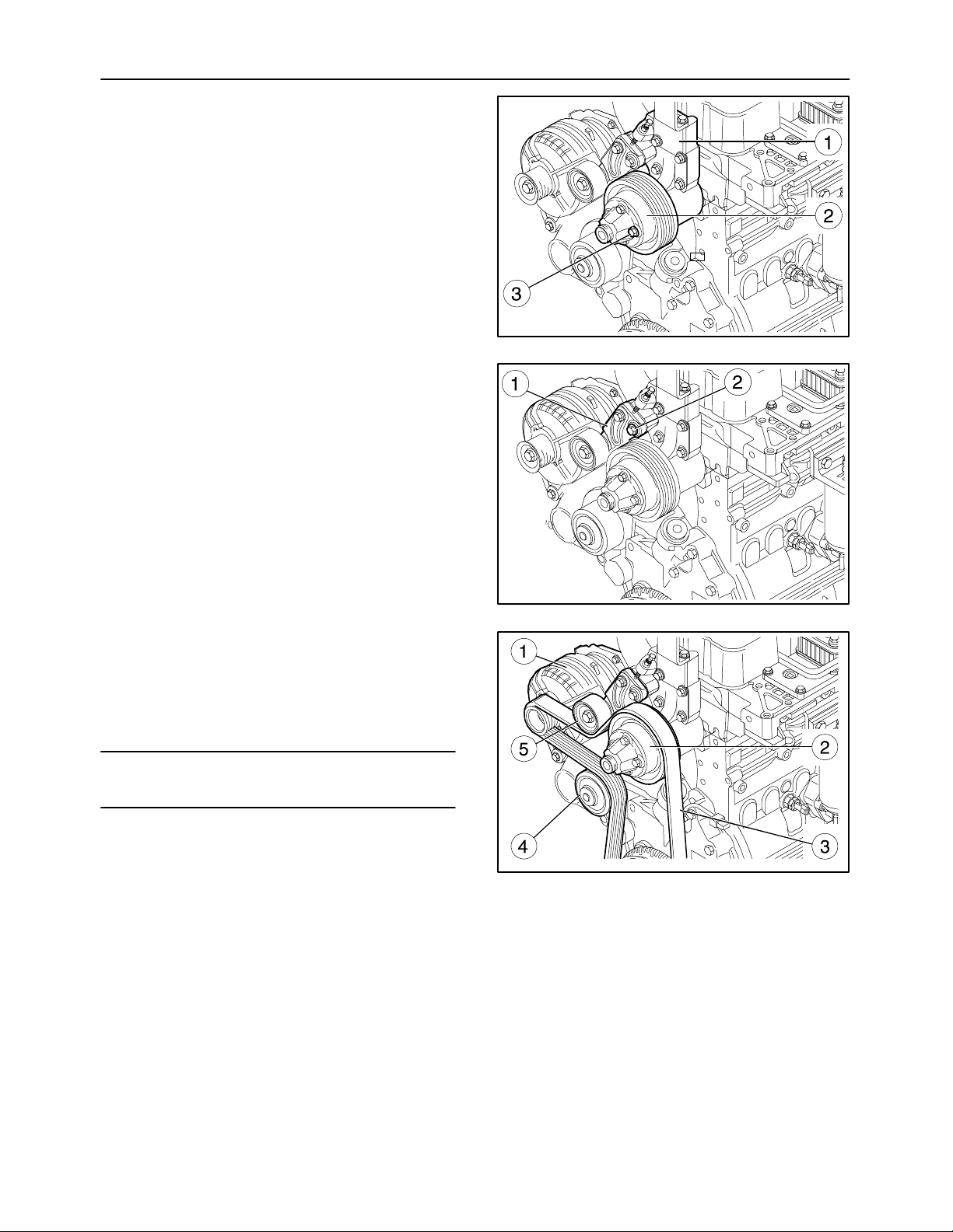
80
SECTION 10 -- ENGINE -- CHAPTER 1
6. Fit the fan pulley (2) on the support (1) with the
screws (3), tightening them to torque.
7. Fit the tightener (1), tightening the bolts (2) and
the tightener nut as directed on page 112.
MIF1153A
164
Fitting the Auxiliary Member Drive Belt
(Disassembly operation 24.)
1. Fit the Poly--V belt (3) on the pulleys of the crankshaft, tightener (5) of the coolant pump (4), alternator (1) and fan (2).
NOTE: Tension the belt correctly as indicated in operation 10 414 10.
MIF1154A
165
MIF1155A
166
Page 81
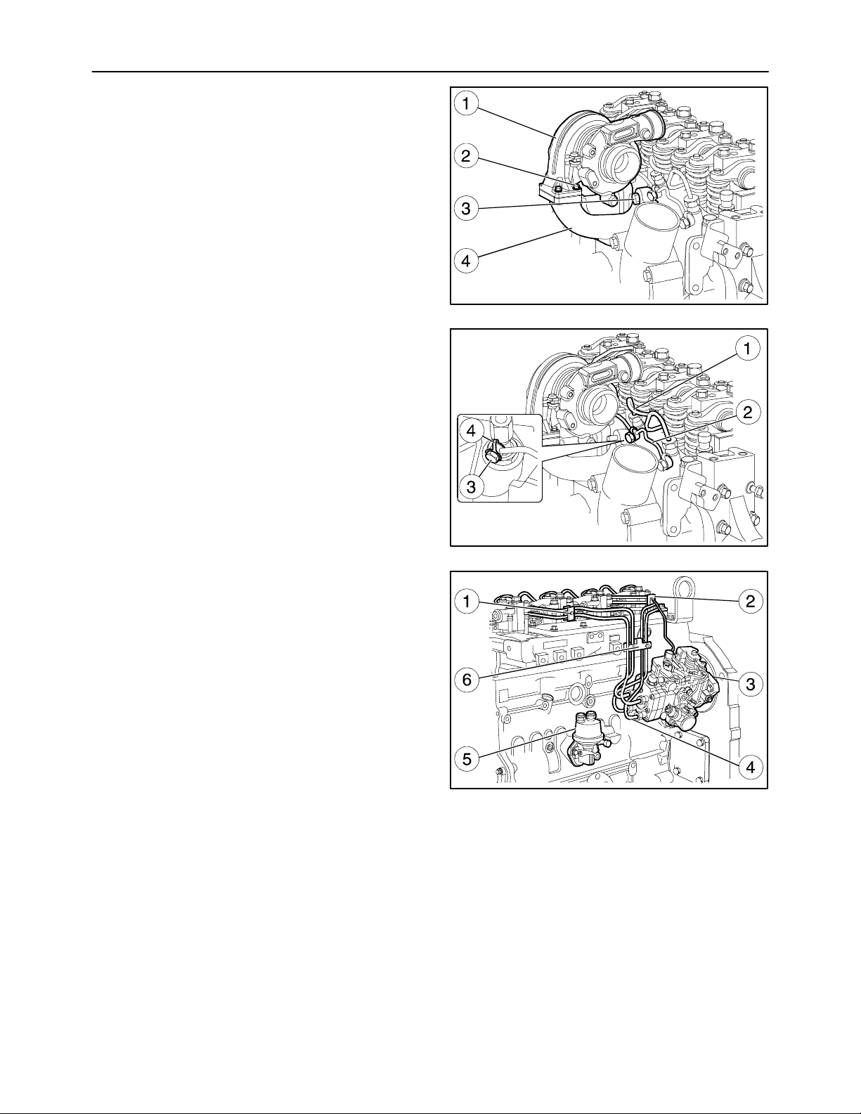
SECTION 10 -- ENGINE -- CHAPTER 1
Fitting the Exhaust Manifold -- Turbine
(Disassembly operations 22. and 23.)
1. Mount the exhaust manifold (4) and tighten the
screws (3) to the torque prescribed on page 12.
2. Fit the turbine (1) with the screws (2).
Fitting the Injector Feed Pipes
(Assembly operations 20. to 21.)
1. Fit the injector feed pipe assembly (1).
2. Fit the injector fuel outlet pipes (2), using the
seals (4) and tighten the screws (3).
81
MIF1156A
167
Fitting the Priming Pump -- Feed Pipes
(Disassembly operations 17. to 19.)
1. Fit the priming pump (5).
2. Fit the injector feed pipes (4) of the injection
pump (3), secure the brackets fixing the pipe assembly (1), (2) and (6) on the cylinder head.
MIF1108A
168
MIF1107A
169
Page 82
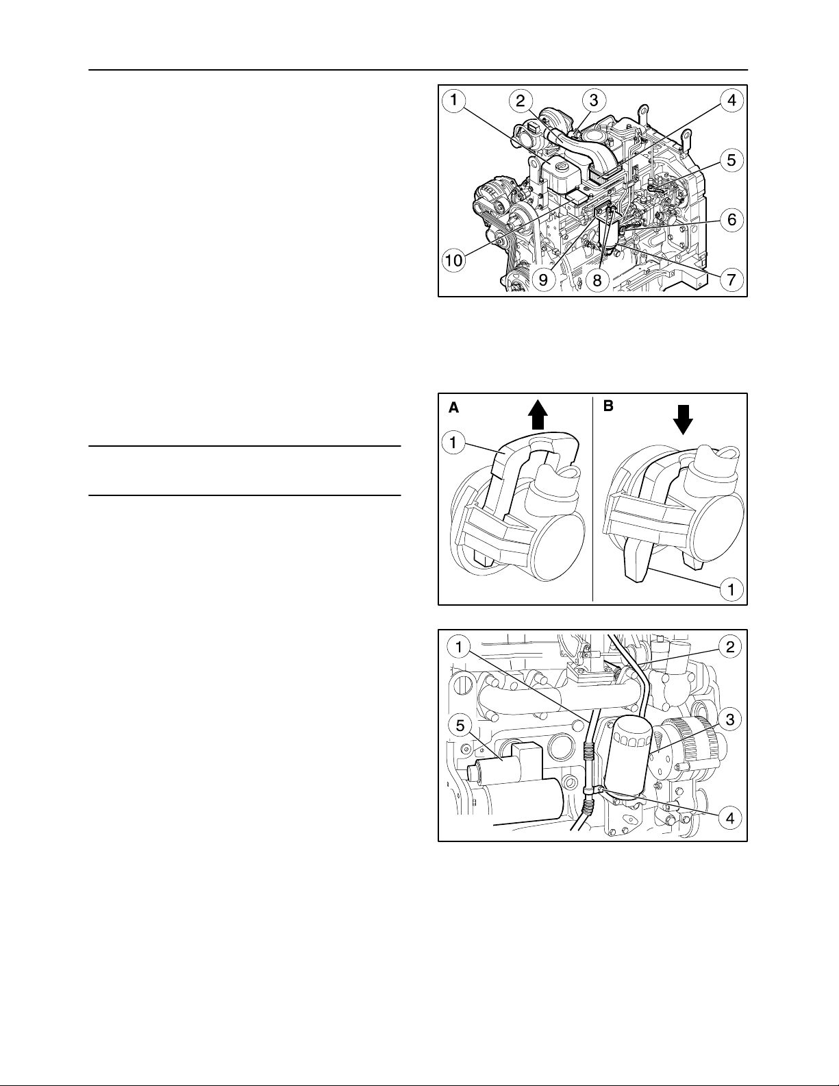
82
SECTION 10 -- ENGINE -- CHAPTER 1
Fitting the Pipes Between the Fuel Supply and
Injection Pumps, Pre--heating System and
Tappet Cover
(Disassembly operations 7. to 16.)
1. Fit the fuel filter mounting (9).
2. Fit the control unit for the heater (10).
3. Fit the heater (4).
4. Fit the fuel filter (7).
5. Fit the LDA system piping (5).
6. Connect the pipes with the quick--fit coupling (6)
and (8) following the guidelines of fig. 171.
7. Fit the tappet covers (1).
8. Connect the engine oil vapor recovery pipe to the
blow--by (3).
9. Fit the intake manifold (2).
10. Press the clip (1) in the direction of the arrow (part
B) and connect the low--pressure pipe. Put the
clip back in its locking position (part A).
MIF1105A
170
NOTE: Figure 171 shows the connectors for the
low--pressure pipes (6) and (8) of figure 170.
A=Pipe locking position on connector.
B=Coupling pipe removal position.
Fitting the Starter Motor
(Disassembly operations 5. and 6.)
1. Fit the oil delivery pipe (2).
2. Fit the turbine oil return pipe (1), the clamp (4), oil
filter (3) and starter motor (5).
MIF0909A
171
MIF1104A
172
Page 83
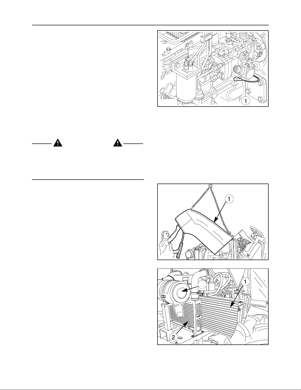
SECTION 10 -- ENGINE -- CHAPTER 1
3. Fit the wiring (1).
4. Fit the fan unit to the fan pulley.
5. Add engine oil through the filler plug.
6. Install the hood as described in operation 90 100 22.
Op 10 102 70
CRANKSHAFT FRONT SEAL
Removal
DANGER
Lift and handle all heavy parts using suitable lifting
equipment.
Make sure that assemblies or parts are supported
by means of suitable slings and hooks. Check that
no one is in the vicinity of the load to be lifted.
83
MIF1103A
173
To access the seal, proceed as follows:
1. Lift the hood (1) and disconnect the battery negative cable.
2. Remove air filter (3) and the radiators of the condenser (1) and air cooler (2).
174
3
175
Page 84
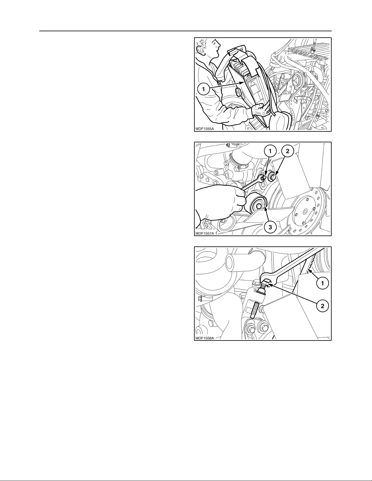
84
3. Remove the engine radiator (1), as indicated in
operation 10 406 10.
4. Loosen the pivot screws (2) and lock screws (1)
of the tightener (3).
SECTION 10 -- ENGINE -- CHAPTER 1
176
5. Loosen the bolt (2) tensioning the belt (1) and remove the belt.
177
178
Page 85
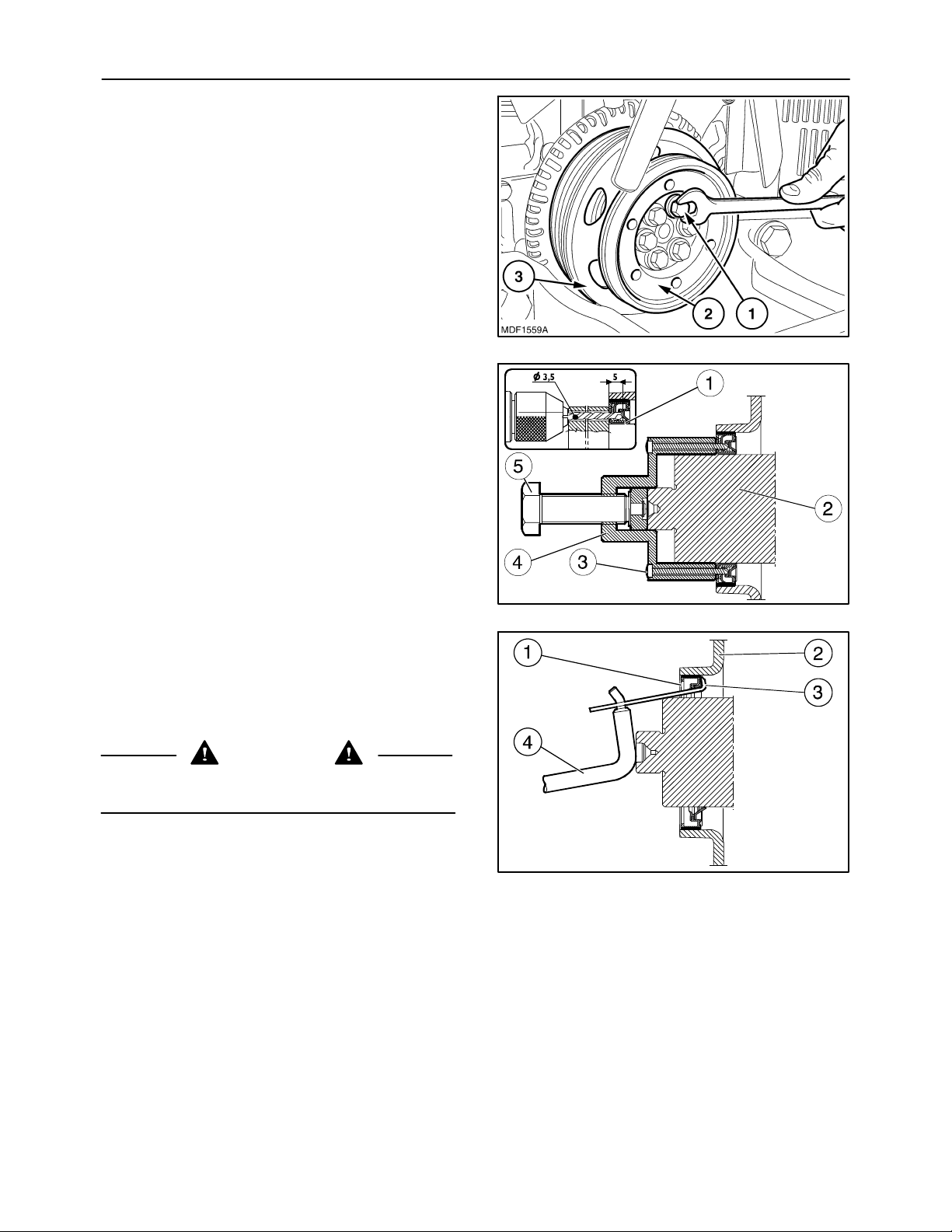
SECTION 10 -- ENGINE -- CHAPTER 1
6. Remove the six retaining bolts (1), the pulley (2)
governing the accessory assemblies and the
fan--alternator--coolant pump pulley (3).
7. Apply tool 380000665 (4) on the front shank (2)
of the crankshaft.
8. Perforate the inner seal (1) with a drill bit
(∅ 0.1377 in. (3.5 mm) through the guide holes
of the tool 380000665 (4), for a depth of
0.1968 in. (5 mm).
9. Secure the tool 380000665 (4) to the seal (1) by
screwing down the screws (3) supplied.
85
179
10. Extract the seal (1) by screwing down the screw
(5).
11. Fit the tie rod (3) of the tool 380000669 to the outer seal (1) as shown in the figure and with the lever (4), extract it from the front cover (2).
12. To assemble and install, proceed as follows:
CAUTION
Always use appropriate tools to align fixing
holes. NEVER USE FINGERS OR HANDS.
MIF0916A
180
MIF0917A
181
Page 86
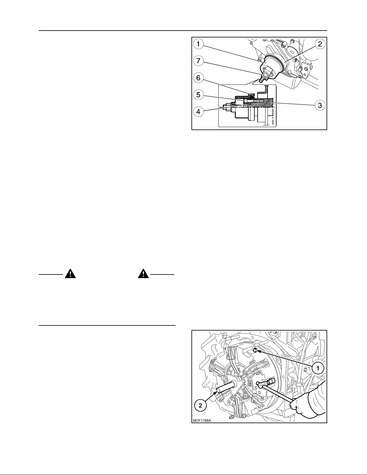
86
Installation
To fit the front seal on the crankshaft, proceed as follows:
1. Fit part (4) of tool 380000666 on the front shank
(3) of the crankshaft. Secure it with the screws (5)
and spline the new seal (6) onto it. Position part
(1) on part (4), screw down the nut (7) until the
seal (6) is completely fitted in the front cover (2).
2. Fit the fan--alternator--coolant pump pulley, the
accessory assembly pulley and the six retaining
bolts.
3. Refit the transmission belt on the pulleys, adjust
it with the tensioning screw and lock the tightener, tightening the two retaining and pivot screws.
4. Refit the engine radiator as described in operation 10 406 10.
SECTION 10 -- ENGINE -- CHAPTER 1
MIF1001A
182
5. Refit the condenser radiator, see operation 50 200 72.
6. Reconnect the negative battery cable and close
the hood.
Op 10 102 74
CRANKSHAFT REAR SEAL
Removal
DANGER
Lift and handle all heavy parts using suitable lifting equipment.
Make sure that assemblies or parts are supported by means of suitable slings and hooks.
Check that no one is in the vicinity of the load to
be lifted.
To access the seal, proceed as follows:
1. Remove the clutch as described in operation 18 11 010.
183
Page 87
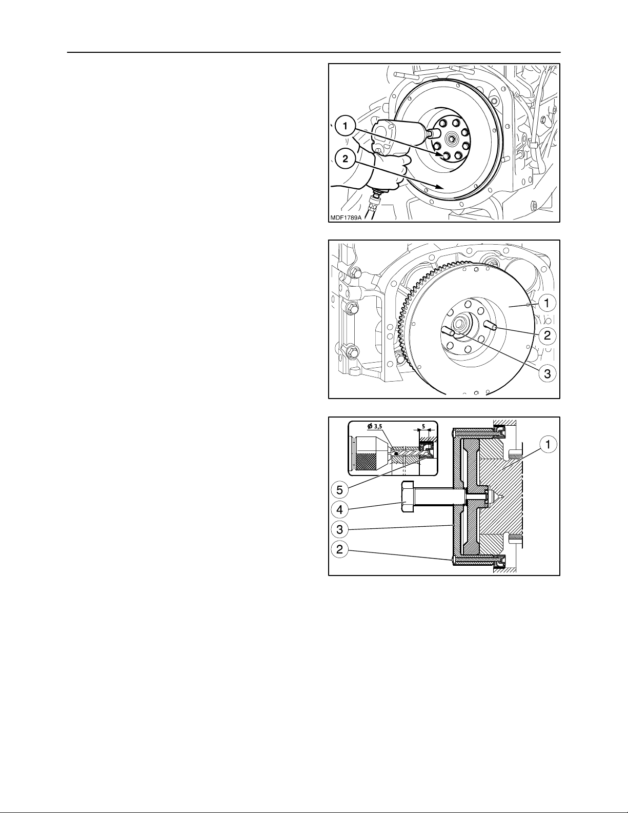
SECTION 10 -- ENGINE -- CHAPTER 1
2. Remove the eight screws (1) fixing the engine flywheel (2).
3. Screw two pins (2) of the appropriate length into
the holes in the crankshaft (3).
Slightly extract the engine flywheel (1) so it can
be slung and then and put down in a specific
wooden container with the hoist.
87
184
4. Apply tool 380000663 (3) on the rear shank (1)
of the crankshaft.
5. Perforate the inner seal (5) with a drill bit
(∅ 0.1377 in. (3.5 mm) through the guide holes
of the tool 380000663 (3), for a depth of
0.1968 in. (5 mm).
6. Secure the tool 380000663 (3) to the seal (5) by
screwing down the screws (2) supplied.
7. Extract the seal (5) by screwing down the screw
(4).
MIF1116A
185
MIF0927A
186
Page 88
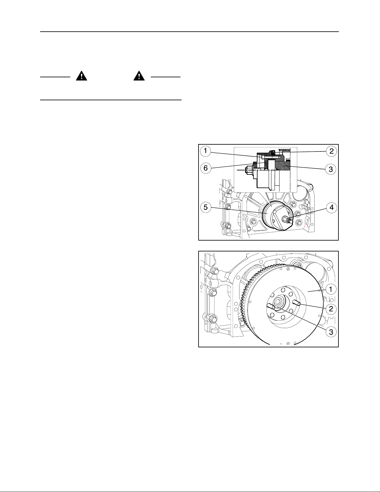
88
SECTION 10 -- ENGINE -- CHAPTER 1
8. To assemble and install, proceed as follows:
Installation
CAUTION
Always use appropriate tools to align fixing
holes. NEVER USE FINGERS OR HANDS.
To fit the front seal on the crankshaft, proceed as follows:
1. Fit part (6) of tool 380000664 on the rear shank
(3) of the crankshaft. Secure it with the screws (1)
and spline the new seal (2) onto it. Position part
(5) on part (6), screw down the nut (4) until the
seal (2) is completely fitted in the flywheel casing.
2. With a hoist and appropriate slinging, insert the
engine flywheel (1) on the pins (2) described
above, pushing it into contact with the crankshaft
(3).
MIF1145A
187
MIF1116A
188
Page 89
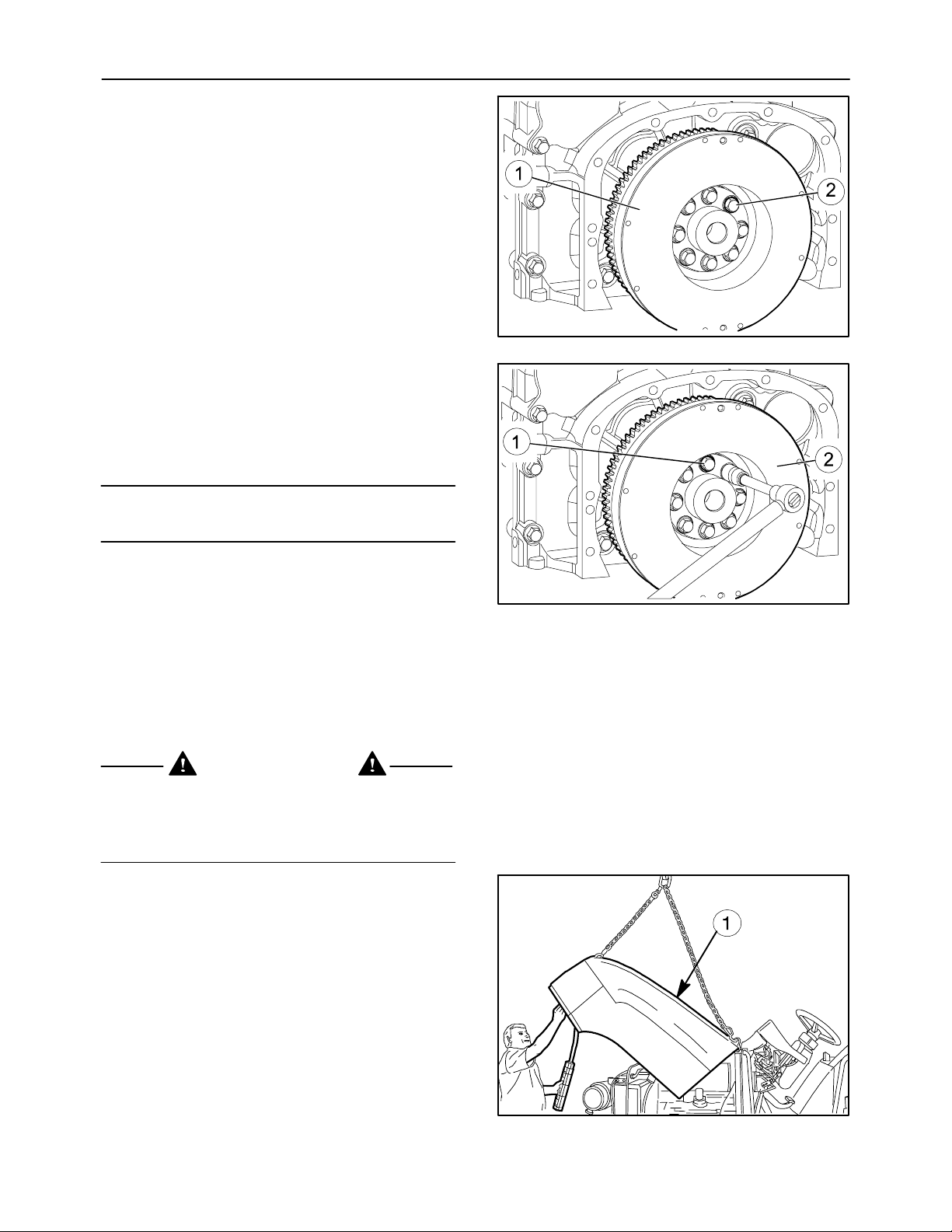
SECTION 10 -- ENGINE -- CHAPTER 1
3. Manually tighten the bolts (2) retaining the flywheel (1) to the crankshaft.
4. Tighten the bolts (1) securing the engine flywheel
(2) in two successive stages as described on
page 13:
st
-- 1
-- 2
NOTE: Tightening to an angle is done with tool
380001001.
phase, tightening with torque wrench to
a torque of 30 ± 5Nm;
nd
phase, tightening to an angle of 60°±5°.
89
MIF1115A
189
5. Refit the clutch as described in operation 18 110 10.
Op 10 106 12
VALVE--ROCKER ARM CLEARANCE
Removal
WARNING
Handle all parts carefully. Do not put your hands
or fingers between parts. Wear the prescribed
safety clothing, including goggles, gloves and
safety footwear.
1. Remove the hood (1) as described in operation 90 100 22.
2. Disconnect the battery negative lead.
MIF1146A
190
191
Page 90
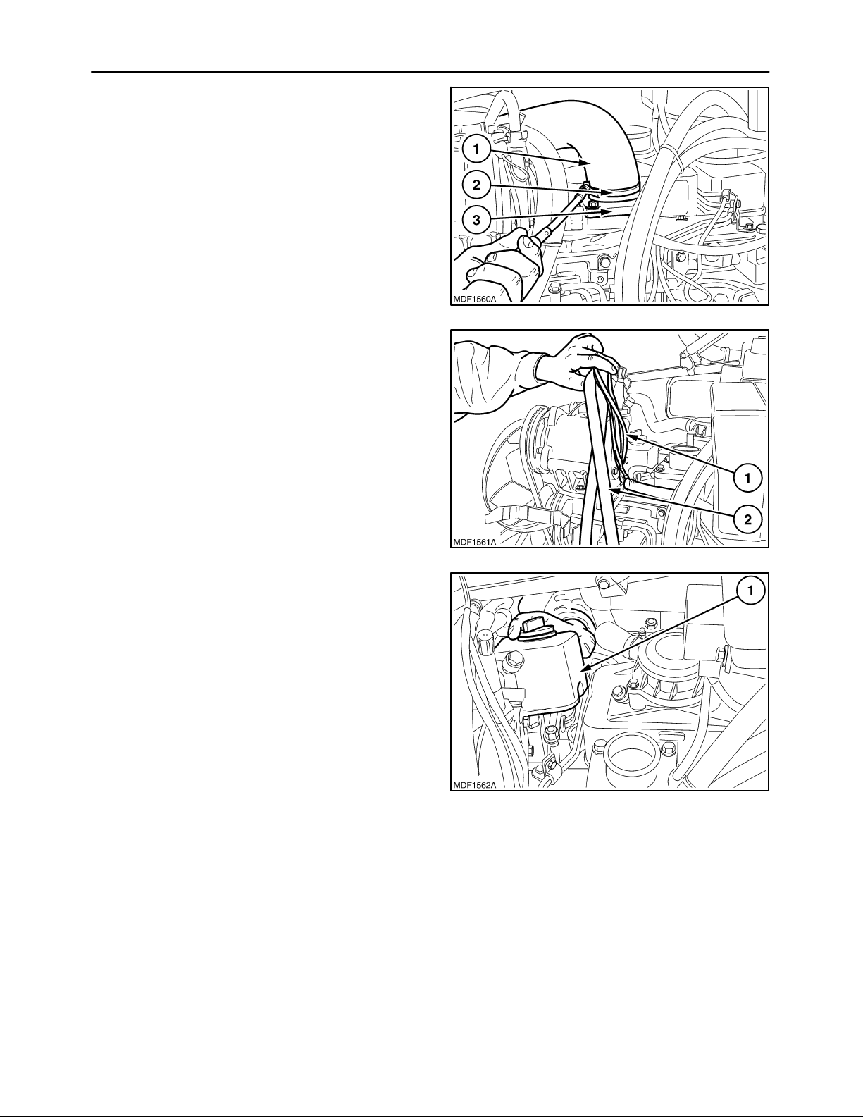
90
3. Remove the clamp (2) and extract the pipe (1)
connecting the intake manifold (3) to the air filter.
4. Remove the plastic retaining clamps, from the
cab heater water delivery--return pipes (2) and
those of the electric cables (1), moving the pipes
and cables on the compressor as described in
the figure.
SECTION 10 -- ENGINE -- CHAPTER 1
192
5. Remove the retaining bolt and the front tappet inspection cover (1) together with the cover base
seal.
193
194
Page 91
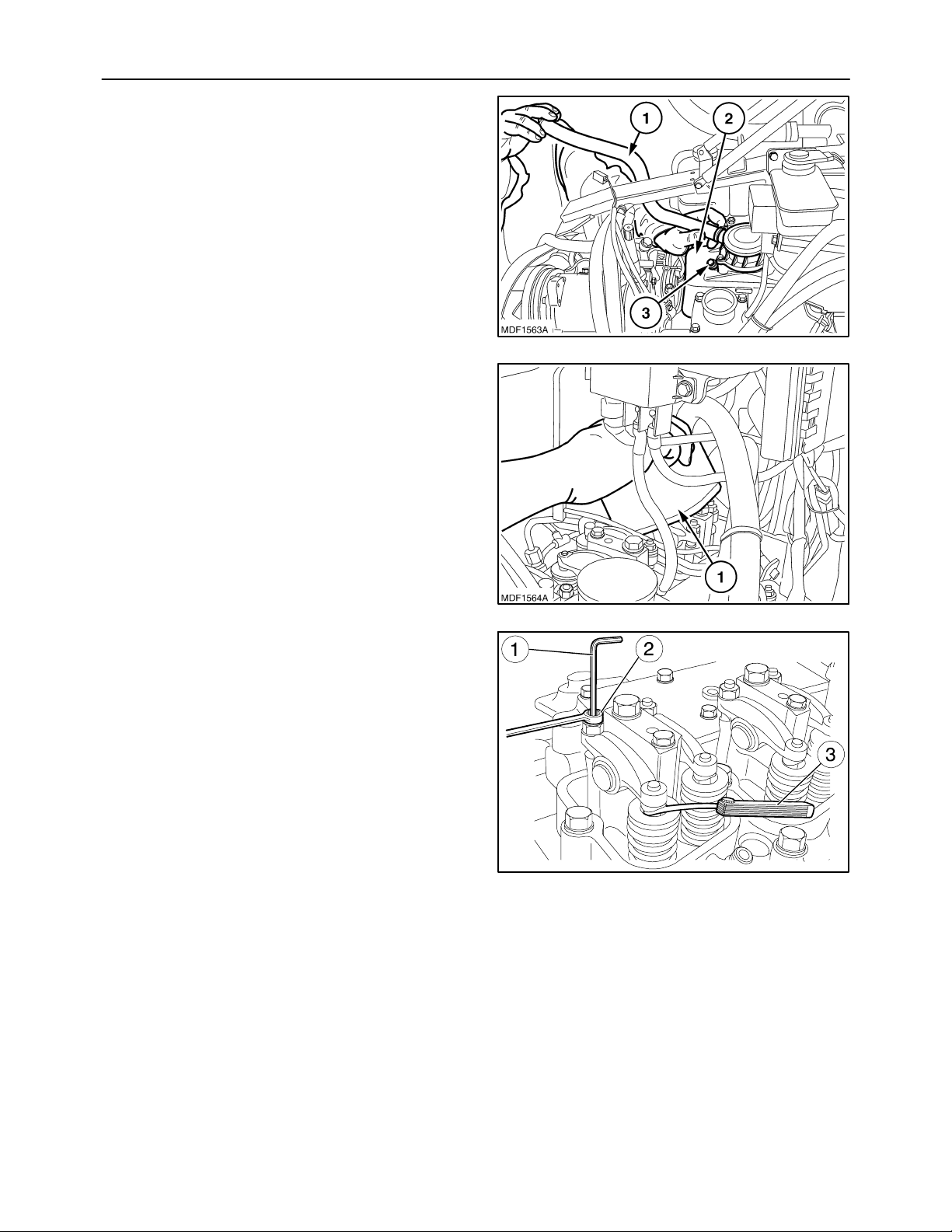
SECTION 10 -- ENGINE -- CHAPTER 1
6. Remove the two retaining bolts (3) and the central tappet inspection cover (2) together with the
engine vapor intake pipe (1) and the cover base
seal.
7. Remove the retaining bolt and the rear tappet inspection cover (1) together with the cover base
seal.
91
195
8. After taking off the covers, adjust the clearance
between the rocker arms and valves using an Allen wrench (1), box wrench (2) and feeler gauge
(3).
The working clearance should be:
-- inlet valves =0.30± 0.05 mm
(0.0118 ± 0.019 in)
-- exhaust valves =0.55± 0.05 mm
(0.0216 ± 0.0019 in).
196
MIF1016A
197
Page 92
92
9. Take the cylinder where the clearance is to be adjusted into the end--of--compression phase; the
valves in the cylinder are closed, whilst those on
the symmetrical cylinder are rocking.
-- The symmetrical cylinders are 1 -- 4 and 3 -- 2.
-- FIRING ORDER 1 -- 3 -- 4 -- 2
SECTION 10 -- ENGINE -- CHAPTER 1
Balancing valves
of cylinder no.
Adjust valve clearance of cylinder no.
Installation
Proceed as follows:
1. Fit the rear tappet inspection cover together with
the cover base seal and tighten the retaining bolt
to the torque stated on page 12.
2. Fit the central tappet inspection cover together
with the engine vapor inlet pipe and the cover
base seal, then tighten the retaining bolts to the
torque stated on page 12.
3. Fit the front tappet inspection cover together with
the cover base seal and tighten the retaining bolt
to the torque stated on page 12.
4. Reposition the cab water delivery--return pipes
and those of the electric cables, inserting new
plastic retaining clamps.
5. Insert the intake manifold--air filter connecting
pipe on the intake manifold and insert the retaining clamp.
1 3 4 2
4 2 1 3
6. Install the hood as described in operation 90 100 22.
7. Reconnect the battery negative lead.
Page 93
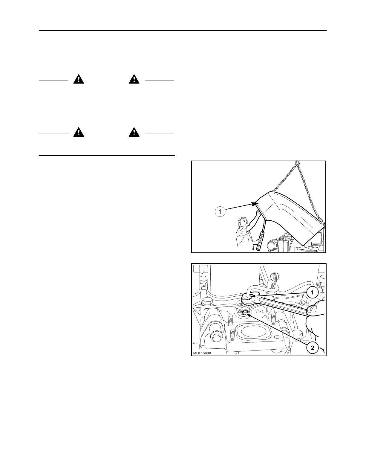
SECTION 10 -- ENGINE -- CHAPTER 1
Op 10 218 30
ENGINE INJECTOR
Removal
CAUTION
Handle all parts carefully. Do not put your hands
or fingers between parts. Wear the prescribed
safety clothing, including goggles, gloves and
safety footwear.
CAUTION
Always use appropriate tools to align fixing
holes. NEVER USE FINGERS OR HANDS.
Proceed as follows:
1. Lift the hood and disconnect the battery negative
cable.
93
2. Disconnect the electrical connection of hood and
remove the hood (1).
3. Remove the diesel delivery (1) and recovery (2)
fittings from the injectors, then remove the relevant pipes.
198
199
Page 94
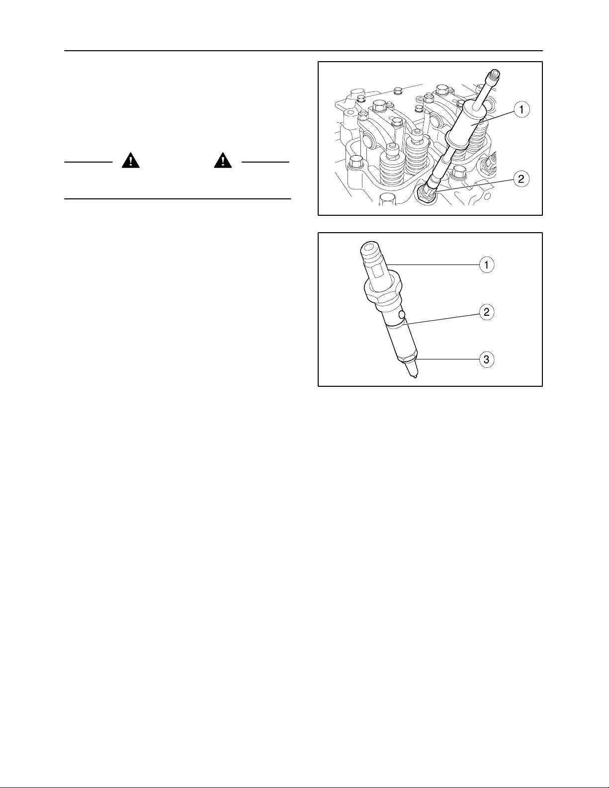
94
4. Remove the injectors (2) with tool 380000671 (1)
and extract them from the cylinder head.
5. Remove the threaded parts retaining the injectors from the cylinder head.
Installation
To refit, proceed as follows:
SECTION 10 -- ENGINE -- CHAPTER 1
CAUTION
Always use appropriate tools to align fixing
holes. NEVER USE FINGERS OR HANDS.
1. Fit the threaded parts retaining the injectors on
the cylinder head.
2. On the injector (1), mount a new seal (2) lubricated with Vaseline and a new washer (3).
3. Fit the injectors in the seats on the cylinder head
and tighten them with a torque wrench to the
torque prescribed on page 12.
200
4. Fit the new seals on the fuel manifolds.
5. Fit the diesel delivery and recovery pipes and fittings on the injectors.
6. Fit the air filter dust ejector pipe, its clamp and the
four rear nuts retaining the silencer to the exhaust manifold.
7. Fit the three rear retaining bolts of the exhaust silencer.
8. Install the hood as described in operation 90 100 22.
9. Lower the hood and reconnect the battery negative cable.
201
Page 95
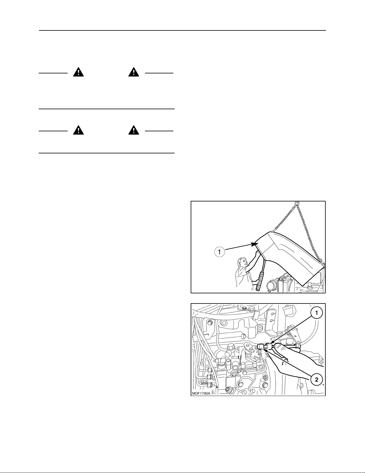
SECTION 10 -- ENGINE -- CHAPTER 1
Op 10 246 14
BOSCH INJECTION PUMP
Removal
CAUTION
Handle all parts carefully. Do not put your hands
or fingers between parts. Wear the prescribed
safety clothing, including goggles, gloves and
safety footwear.
CAUTION
Always use appropriate tools to align fixing
holes. NEVER USE FINGERS OR HANDS.
Proceed as follows:
95
1. Lift the hood and disconnect the battery negative
cable.
2. Disconnect the electrical connection of hood and
remove the hood (1).
3. Remove the accelerator retaining spring (1) and
extract the lever (2).
202
203
Page 96
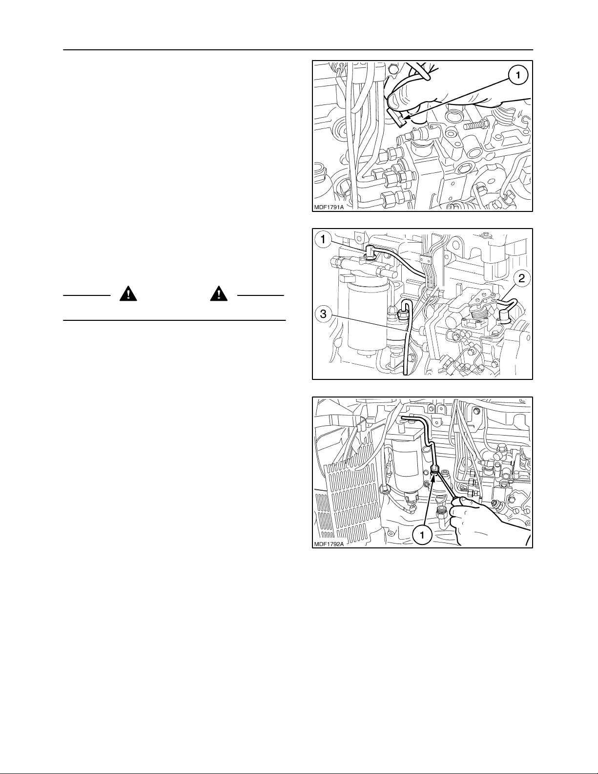
96
4. Disconnect the engine stop electromagnet
wire (1).
5. Remove the quick couplers (1) on the filter
and (2) on the injection pump, remove the injection pump supply pipe.
Remove the pipe (3) coming from the tank.
SECTION 10 -- ENGINE -- CHAPTER 1
CAUTION
Make the vehicle safe and put the gear into neutral.
204
6. Remove the quick couplers and pipe (1) installed
between the fuel filter and fuel pump.
MIF1161A
205
206
Page 97
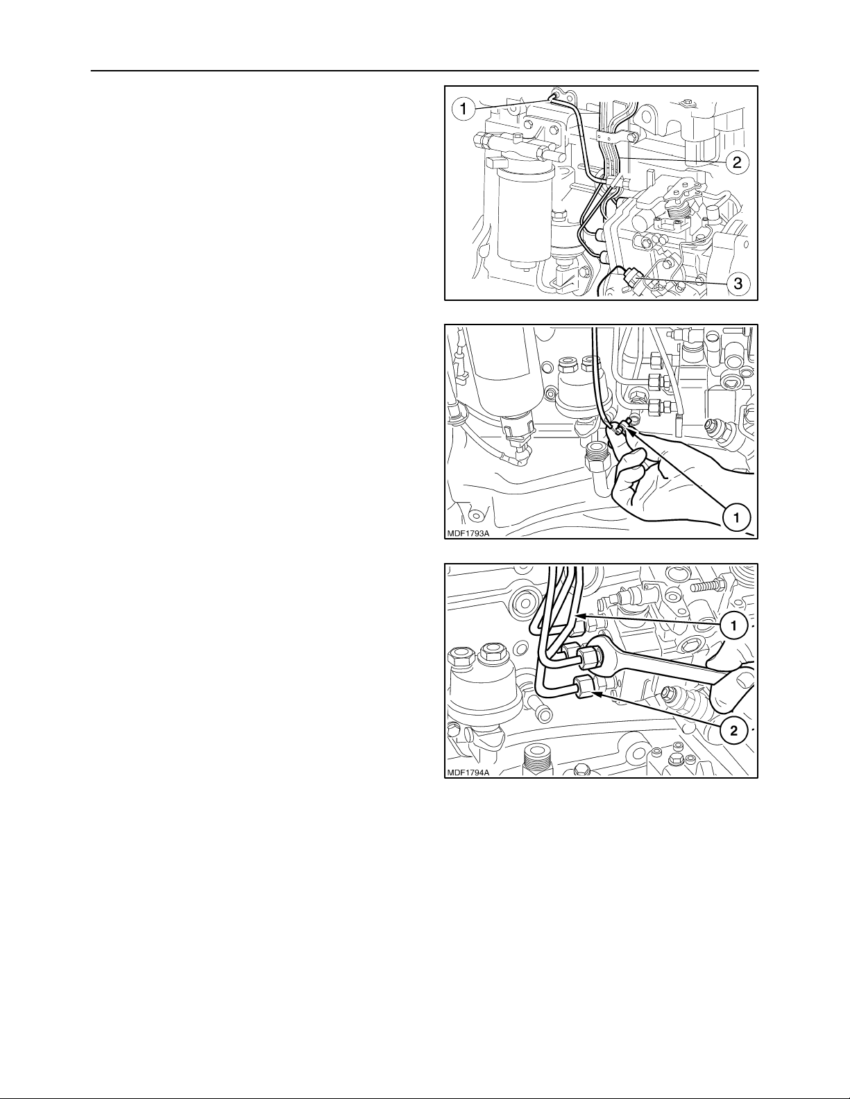
SECTION 10 -- ENGINE -- CHAPTER 1
7. Remove the fittings of the pipes (2) connecting
the injection pump--injectors, the pipe (1) connected to the thermostarter device and the electrical connection of the engine stop device (3).
8. Disconnect the electrical connection (1) for measuring the engine oil pressure.
97
MIF1163A
207
9. Remove the four fittings (2) connecting the injection pump / injectors and the pipes (1).
208
209
Page 98
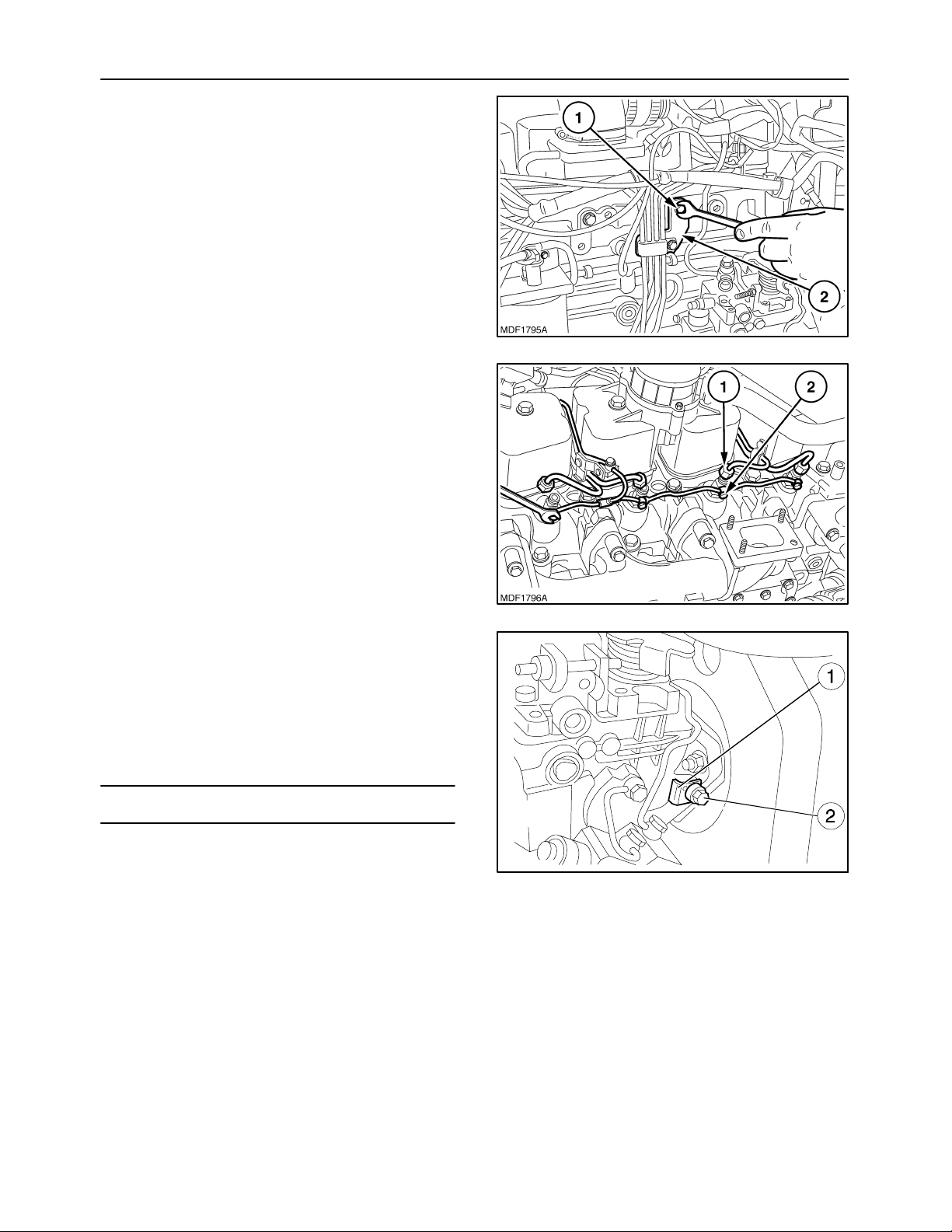
98
10. Remove the retaining bolts (1) and the three
brackets (2) retaining the pipes, inserted on the
injection pump/injector connection line.
11. Remove the fittings (1) of the injector diesel delivery pipes and the fittings (2) of the injection pump
diesel return pipe, then detach the pipes.
12. Lock the engine flywheel with appropriate
means.
SECTION 10 -- ENGINE -- CHAPTER 1
210
13. Before removing the injection pump, do the timing and lock the engine flywheel with cylinder
no. 1 at T.D.C. as indicated on page 100, using
tools 380000988 and 380000732. Then loosen
the bolt (2), remove the “L” spacer (1) and lock
the screw (2) in order to keep the pump in time
with the engine flywheel.
NOTE: Keep the “L” spacer with the pump casing.
211
MIF0920A
212
Page 99
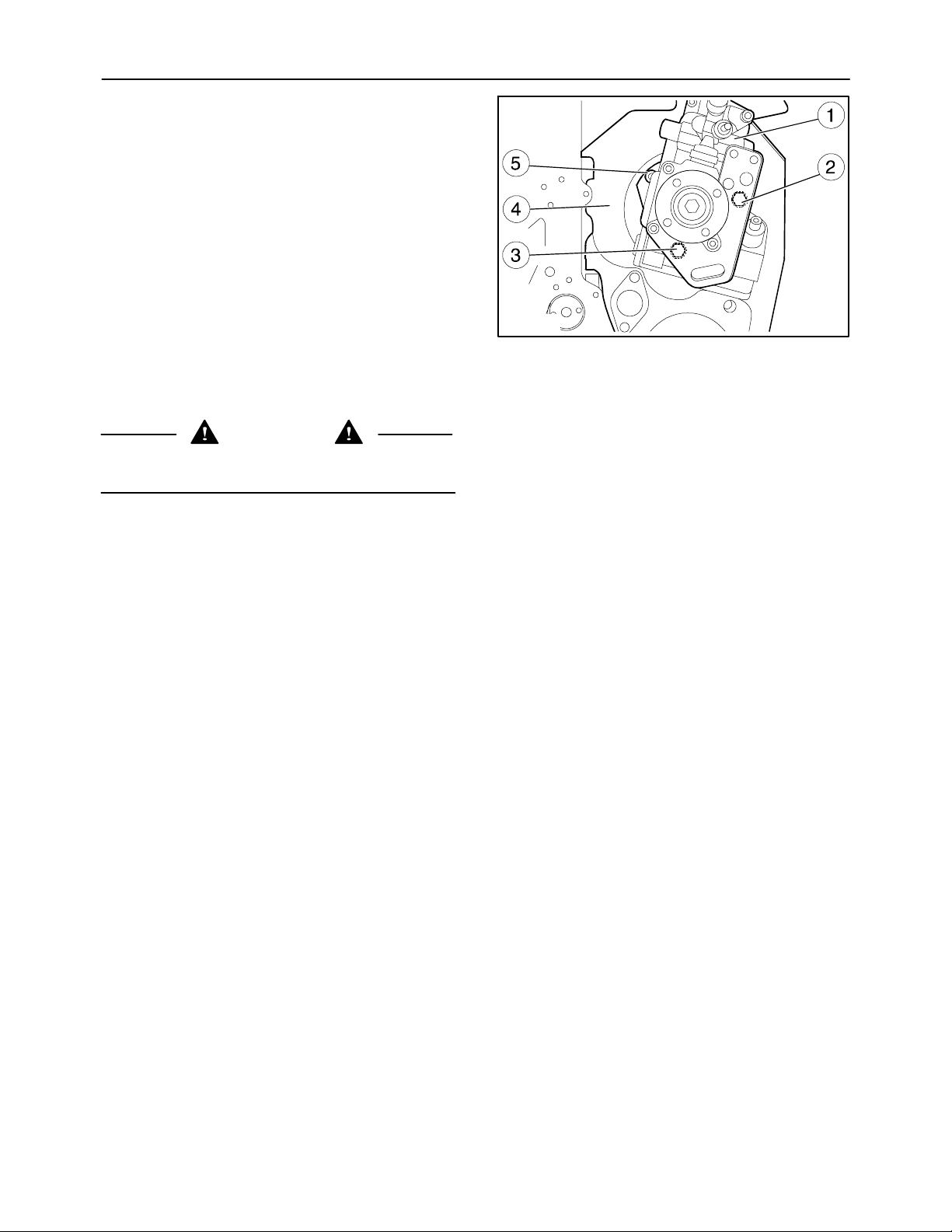
SECTION 10 -- ENGINE -- CHAPTER 1
14. Remove the three nuts (2) (3) (5) securing the injection pump (1) to the engine flywheel casing (4)
and extract it from its housing.
Installation
To refit the injection pump, proceed as follows:
CAUTION
Always use appropriate tools to align fixing
holes. NEVER USE FINGERS OR HANDS.
1. Respect the tightening torques prescribed on
page 12.
2. When refitting the BOSCH injection pump, insert
the stud bolts in the engine flywheel casing into
the mating holes on the pump flanging.
3. Do the timing for the injection pump in relation to
the drive gear, proceeding as described on
page 100.
4. Then loosen the retaining and safety bolt of the
injection pump timing.
99
MIF0922A
213
5. Reinsert the
bolts.
6. Free the engine flywheel, take out the tools
380000988 and 380000732 and refit the starter
motor.
7. Reconnect the pipes and the fittings of the diesel
delivery pipes to the injectors and the fittings of
the diesel return pipe to the injection pump.
8. Fit the three retaining brackets, insert the pipes
on the line that connect the injection pump to the
injectors, tightening the retaining bolts.
9. Reconnect the four pipes connecting the injection pump / injectors, tightening their fittings.
10. Reconnect the electrical connection for measuring the engine oil pressure.
11. Install the fittings of the pipes connecting the injection pump--injectors, the pipe connected to
the thermostarter device and the electrical connection of the engine stop device.
L spacer and tighten the retaining
Page 100
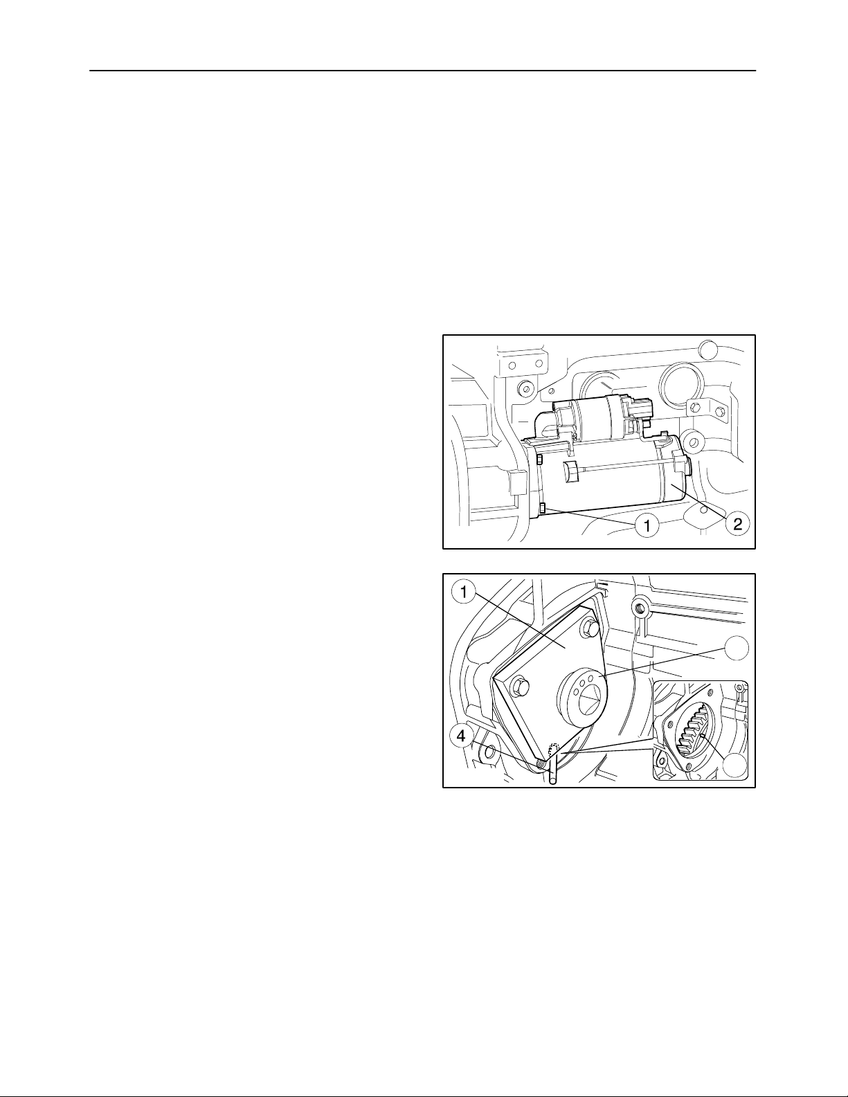
100
12. Reconnect the pipe installed between the fuel filter and the fuel pump and reinsert the quick couplers.
13. Fit the pipe supplying the injection pump, connecting the quick couplers on the filter and on the
injection pump.
14. Fit the pipe coming from the tank.
15. Reconnect the engine stop electromagnet cable.
16. Fit the throttle control lever and its retaining clip.
17. Install the hood.
18. Reconnect the battery negative cable and lower
the hood.
Timing
When replacing the injection pump, bear in mind that
it is supplied as a spare part already set for cylinder
No. 1 at T.D.C.
Proceed as follows:
SECTION 10 -- ENGINE -- CHAPTER 1
1. Unscrew the bolts (1) and remove the starter motor (2).
2. Fit the bracket tool 380000988 (1), retaining the
gear for turning the engine flywheel tool
380000732 (2).
3. Slowly turn the engine flywheel (3) and at the
same time press on the pin (4), supplied with tool
380000988, in order to insert the pin (4) into the
seat in the engine flywheel (3).
MIF1172A
214
2
3
MIF1173A
215
 Loading...