


HDP5000 High Definition Card
Printer/Encoder User Guide (Rev. 1.4)
•HDP5000 single-side
•HDP5000 dual-side
•HDP5000 single-side (with single-side lamination)
•HDP5000 dual-side (with single-side lamination)
•HDP5000 single-side (with dual-side lamination)
•HDP5000 dual-side (with dual-side lamination)
Part Number: L000950
RESTRICTED USE ONLY |
Fargo Electronics, Inc. |
HDP5000 High Definition Card Printer/Encoder User Guide (Rev. 1.4), property of Fargo Electronics, Incorporated
Copyright © 2007 by Fargo Electronics, Incorporated. All rights reserved. Printed in the United States of America. Exclusive permission is granted to authorized resellers of Fargo products to reproduce and distribute this copyrighted document to authorized Fargo customers. The revision number for this document will be updated to reflect changes, corrections, updates and enhancements to this document.
Revision Control |
Date |
Document Title |
|
Number |
|
|
|
|
|
|
|
Revision 1.4 |
1 December 2008 |
HDP5000 High Definition Card Printer/Encoder |
|
|
|
|
User Guide |
|
|
|
|
Revision 1.3 |
15 |
August 2008 |
HDP5000 High Definition Card Printer/Encoder |
|
|
|
User Guide |
|
|
|
|
Revision 1.2 |
30 |
October 2007 |
Same document title |
|
|
|
|
Revision 1.1 |
15 |
July 2007 |
Same document title |
|
|
|
|
Revision 1.0 |
15 |
April 2007 |
Same document title |
|
|
|
|
These reference documents were thoroughly reviewed to provide Fargo with professional and international standards, requirements, guidelines and models for our technical, training and User documentation. At all times, the Copyright Protection Notice for each document was adhered to within our Fargo documentation process. This reference to other documents does indicate that Fargo is an ISO-certified company at this time.
•ANSI/ISO/ASQ Q9001-2000 American National Standard, (sub-title) Quality Management Systems – Requirements (published by the American Society of Quality, Quality Press, P.O. Box 3005, Milwaukee, Wisconsin 53201-3005)
•The ASQ ISO 9000:2000 Handbook (editors, Charles A. Cianfrani, Joseph J. Tsiakals and John E. West; Second Edition; published by the American Society of Quality, Quality Press, 625 N. Plankinton Avenue, Milwaukee, Wisconsin 53203)
•Juran’s Quality Handbook (editors, Joseph M. Juran and A. Blanton Godfrey; Fifth Edition, McGraw-Hill)
Any questions regarding changes, corrections, updates or enhancements to this document should be forwarded to:
Fargo Electronics, Incorporated Support Services
6533 Flying Cloud Drive
Eden Prairie, MN 55344 (USA) (952) 941-0050
FAX: (952) 946-8492 www.fargo.com
HDP5000 High Definition Card Printer/Encoder User Guide (Rev. 1.4) |
ii |
RESTRICTED USE ONLY |
Fargo Electronics, Inc. |
Table of Contents
Section 1: Printer Overview _________________________________________________ 1-1
How to use the guide_________________________________________________________________ 1-1 Safety Messages (review carefully)______________________________________________________ 1-2 HDP5000 Process Flow (in table format) _________________________________________________ 1-3 Reviewing the HDP5000 Boot-up Sequence ____________________________________________ 1-3 Reviewing the HDP5000 Sequence of Operations ________________________________________ 1-4 Reviewing the Lamination Module Boot-up Sequence ____________________________________ 1-6 Reviewing the Lamination Module Sequence of Operations ________________________________ 1-7
Section 2: Specifications ____________________________________________________ 2-1
Safety Messages (review carefully)______________________________________________________ 2-1 Introduction ________________________________________________________________________ 2-2 Reviewing the HDP5000 Printer Overview table ___________________________________________ 2-2 Reviewing the HDP5000 Package ____________________________________________________ 2-3 Reviewing the HDP5000 (front)______________________________________________________ 2-3 Reviewing the HDP5000 Card Printer _________________________________________________ 2-4 Regulatory Compliances ______________________________________________________________ 2-5 Agency Listings_____________________________________________________________________ 2-5 FCC Rules ______________________________________________________________________ 2-6 Environmental Protection (China-RoHS)_______________________________________________ 2-6 Technical Specifications ______________________________________________________________ 2-7 Functional Specifications ____________________________________________________________ 2-16 Printer Components: Resin Thermal Transfer to USB Interface Port ________________________ 2-17 Printer Components: LCD and Softkey Control Pad_____________________________________ 2-18 Printer Components: Print Ribbons __________________________________________________ 2-20 Printer Components: Blank Cards ___________________________________________________ 2-21 Printer Components: Card Input and Output Hoppers____________________________________ 2-23 Printer Components: Card Output Hopper and Reject Hopper _____________________________ 2-23 Printer Unit: Reviewing the Card Lamination Module ___________________________________ 2-24 Printer Components: Transfer Roller_________________________________________________ 2-25 Reviewing the Overlaminates _________________________________________________________ 2-26 Reviewing the Thermal Transfer Film and PolyGuard Overlaminates________________________ 2-26 Reviewing the CR-80 Patch Size ____________________________________________________ 2-27 Reviewing the Overlaminate Design _________________________________________________ 2-27
Section 3: Installation Procedures ____________________________________________ 3-1
Safety Messages (review carefully)______________________________________________________ 3-1 Introduction ________________________________________________________________________ 3-2 Time Requirement ________________________________________________________________ 3-2 System Requirements ______________________________________________________________ 3-2 Inspection – HDP5000 _____________________________________________________________ 3-2 Unpacking the Printer______________________________________________________________ 3-2 Unpacking the Printer______________________________________________________________ 3-4 Choosing a Good Location __________________________________________________________ 3-5 About Moisture Condensation _______________________________________________________ 3-5 Printer Loading Procedures ____________________________________________________________ 3-6 Loading the Print Ribbon ___________________________________________________________ 3-6 Loading the Clear HDP Transfer Film _________________________________________________ 3-9 Inserting the Card Cleaning Roller ___________________________________________________ 3-12 Loading the Overlaminate _________________________________________________________ 3-15 Loading the Blank Cards __________________________________________________________ 3-18 Connecting Power to HDP5000 Printer and Lamination Module ___________________________ 3-20 Printer Driver Installation Procedures ___________________________________________________ 3-23
HDP5000 High Definition Card Printer/Encoder User Guide (Rev. 1.4) |
iii |
RESTRICTED USE ONLY |
Fargo Electronics, Inc. |
Installation Procedures ______________________________________________________________ 3-23 Installing the HDP5000 Printer Driver ________________________________________________ 3-23 Printing a Test Print Image ___________________________________________________________ 3-32
Section 4: Accessory Procedures _____________________________________________ 4-1
Safety Messages (review carefully)______________________________________________________ 4-1 Using the Security Lock Slot on the HDP5000_____________________________________________ 4-2 Installation and Removal Procedures Flipper and Lamination Modules__________________________ 4-4 Removing the Output Side Upgrade Cover _____________________________________________ 4-4 Installing the Flipper Module Accessory__________________________________________________ 4-5 Installing the Lamination Module Accessory____________________________________________ 4-7
Section 5: General Troubleshooting __________________________________________ 5-1
LCD Messages _____________________________________________________________________ 5-1 Safety Messages (review carefully)______________________________________________________ 5-2 Troubleshooting - LCD and Printer Error Message Tables. ___________________________________ 5-3 How to use the LCD Error Message Table (example provided)______________________________ 5-4 Troubleshooting with the LCD Error Message Table______________________________________ 5-5 Troubleshooting with the Printer Error Message Table ___________________________________ 5-22 Communications Errors______________________________________________________________ 5-37 Resolving the Communication Errors_________________________________________________ 5-37 Printing a Test Image _______________________________________________________________ 5-39 Reviewing the Alignment Self Test Card ______________________________________________ 5-40 Reviewing the Color Bars Self Test __________________________________________________ 5-41 Reviewing the Device Settings Self Test ______________________________________________ 5-42 Reviewing the Magnetic Self Test ___________________________________________________ 5-44 Reviewing the Resin Self Test ______________________________________________________ 5-45
Section 6: Ethernet Option Section ___________________________________________ 6-1
Introduction ________________________________________________________________________ 6-1 Technical Specification - Ethernet Option ________________________________________________ 6-2 Functional Specification - Ethernet Option ________________________________________________ 6-3
Network Services - Overview ____________________________________________________6-4
Reviewing the Print Server__________________________________________________________ 6-4 Reviewing the Web Page Server _____________________________________________________ 6-4 Reviewing the Network Management Interface __________________________________________ 6-4 Reviewing the Telnet Server ________________________________________________________ 6-4
Network Management Interface _________________________________________________6-5
Telnet Command Line Interface _________________________________________________6-5
Initiating a Telnet Session __________________________________________________________ 6-5 Reviewing the Telnet Command Table ________________________________________________ 6-6
Ethernet Web Pages – Standard Procedures ______________________________________6-12
Reviewing Web page security _________________________________________________________ 6-12 Logging In________________________________________________________________________ 6-13 Accessing the Home page ____________________________________________________________ 6-14 Reviewing the Home Page ___________________________________________________________ 6-15 Reviewing the Home Page Categories and Fields (table)__________________________________ 6-16 Configuring the Network Settings______________________________________________________ 6-17 Accessing the Network Settings page_________________________________________________ 6-17 Reviewing the Interface ___________________________________________________________ 6-18 Reviewing the Current Settings _____________________________________________________ 6-18 Switching to the Automatic IP Address Mode __________________________________________ 6-19 Changing to the Static IP Address Mode ______________________________________________ 6-20 Using the Clear Changes button _____________________________________________________ 6-22
HDP5000 High Definition Card Printer/Encoder User Guide (Rev. 1.4) |
iv |
RESTRICTED USE ONLY |
Fargo Electronics, Inc. |
Using the Media Information page _____________________________________________________ 6-23 Using the TCP/IP page ______________________________________________________________ 6-24 Using the TCP/IP page ____________________________________________________________ 6-25 Using the Printer page _______________________________________________________________ 6-26 Using the System Log page___________________________________________________________ 6-28 Changing the Log Name___________________________________________________________ 6-29 Selecting the Log Type____________________________________________________________ 6-30 Selecting the Log Destination_______________________________________________________ 6-31 Setting up Email Event logging _____________________________________________________ 6-32 Specifying UDP Event logging _____________________________________________________ 6-33 Specifying TCP Event logging ______________________________________________________ 6-35 Using the Administration pages _______________________________________________________ 6-37 Using the System Information page __________________________________________________ 6-37 Changing the Root Password _______________________________________________________ 6-39 Using the Reboot pages______________________________________________________________ 6-40 Rebooting the Printer _____________________________________________________________ 6-40 Upgrading the Main Firmware ______________________________________________________ 6-41 Using the Print Path page ____________________________________________________________ 6-45 Using the Help page ______________________________________________________________ 6-47
Additional Procedures ________________________________________________________6-47
Accessing the Ethernet Status LEDs ____________________________________________________ 6-47 Reviewing the HDP5000 LED Table _________________________________________________ 6-47 Upgrading the Main Firmware with the Fargo Workbench Printer Utility _______________________ 6-48 Restoring the Factory Settings for Ethernet ______________________________________________ 6-50 Resetting the HDP5000 settings _____________________________________________________ 6-50 Changing the HDP5000 LCD Network Settings ________________________________________ 6-50 Accessing the Network Setup Menu__________________________________________________ 6-50 Changing the DHCP Setting________________________________________________________ 6-51 Changing the ANEG setting ________________________________________________________ 6-51 Saving addresses_________________________________________________________________ 6-52 Resetting Passwords ______________________________________________________________ 6-52 Accessing the HDP5000 IP Address _________________________________________________ 6-53
Ethernet Printer Troubleshooting Procedures _____________________________________6-54
Troubleshooting procedures ________________________________________________________ 6-54 Verifying the Printer Connection ____________________________________________________ 6-55 Verifying the Printer IP address _____________________________________________________ 6-55 Verifying that your PC can access the Printer using the ping command ______________________ 6-56 Printing a test page _______________________________________________________________ 6-57
Reviewing Frequently-asked Questions __________________________________________6-58 Glossary of Terms ____________________________________________________________6-65
Section 7: Card Lamination Module __________________________________________ 7-1
Safety Messages (review carefully)______________________________________________________ 7-2 Reviewing the Card Lamination Module _________________________________________________ 7-3 Installing the Card Lamination Module___________________________________________________ 7-4 Introduction _____________________________________________________________________ 7-4 Inspecting the Card Lamination Module _______________________________________________ 7-5 Unpacking the Card Lamination Module _______________________________________________ 7-5 Choosing a proper Location _________________________________________________________ 7-5 Preventing Moisture Condensation____________________________________________________ 7-5 Installing the Lamination Module Accessory____________________________________________ 7-6 Adjusting the Lamination Placement on the Card___________________________________________ 7-8 Adjusting the Card Flattener __________________________________________________________ 7-10
HDP5000 High Definition Card Printer/Encoder User Guide (Rev. 1.4) |
v |
RESTRICTED USE ONLY |
Fargo Electronics, Inc. |
Section 8: Printer Adjustments_______________________________________________ 8-1
Safety Messages (review carefully)______________________________________________________ 8-1 Printing on Alternate Card Stocks_______________________________________________________ 8-2 Selecting the Right Cards and optimizing the HDP Print Process ____________________________ 8-2 Selecting the Appropriate HDP Printer Driver settings ____________________________________ 8-3 Conducting the Tape Adhesion Test___________________________________________________ 8-5 Printer Driver Options________________________________________________________________ 8-8 Installing Printer Driver Updates _____________________________________________________ 8-8 Setting Up the Printer Driver__________________________________________________________ 8-10 Setting up Windows 2000/XP/2003 __________________________________________________ 8-10 Using the OK, Cancel and Help buttons_______________________________________________ 8-10
Using the Card tab ___________________________________________________________8-11
Selecting the Card Size____________________________________________________________ 8-12 Selecting the Card Type ___________________________________________________________ 8-13 Setting the Orientation ____________________________________________________________ 8-17 Specifying the number of Copies ____________________________________________________ 8-18 Selecting the Diagnostics button ____________________________________________________ 8-19 Selecting the Test Print button ______________________________________________________ 8-20 Selecting the About button _________________________________________________________ 8-21 Selecting the Toolbox button _______________________________________________________ 8-22
Using the Device Options tab ___________________________________________________8-23
Detecting Supplies at Print Time Function _______________________________________________ 8-24 Adjusting the Ribbon Type_________________________________________________________ 8-27 Adjusting the Film Type___________________________________________________________ 8-28 Using the Dual Sided Group Functions__________________________________________________ 8-29 Using the Dual Sided - Print Both Sides option _________________________________________ 8-30 Using the Print Both Sides - Split 1 Set of Ribbon Panels option ___________________________ 8-31 Using the Print Both Sides - Print Back Image on Front of Card option ______________________ 8-32 Using the Dual Sided - Print Back Side Only option _____________________________________ 8-33 Using the Options Group_____________________________________________________________ 8-34 Using the Rotate Front 180 Degrees or Rotate Back 180 Degrees options ____________________ 8-35 Using the Disable Printing option____________________________________________________ 8-36 Using the Dual Pass and Invert F-Panel Image options ___________________________________ 8-37
Using the Image Color tab _____________________________________________________8-38
Using the Quality – Color Matching dropdown _________________________________________ 8-40 Adjusting for the Resin Dither ______________________________________________________ 8-44 Using the Advanced Image Color window_____________________________________________ 8-45 Using the Default button on the Image Color tab ________________________________________ 8-51
Using the Image Transfer tab___________________________________________________8-52
Adjusting the Image Position controls ________________________________________________ 8-53 Adjusting the Transfer Dwell Time and Temperature ____________________________________ 8-55 Using the Default button___________________________________________________________ 8-59
Using the Magnetic Encoding tab _______________________________________________8-60
Using the Encoding Mode dropdown list ______________________________________________ 8-61 Selecting the Coercivity/Magnetic Track ______________________________________________ 8-66 Reviewing the Shift Data Left Function _______________________________________________ 8-67 Reviewing the Magnetic Track Options _______________________________________________ 8-68 Using the Magnetic Track Options___________________________________________________ 8-70 Using the Character Size buttons ____________________________________________________ 8-72 Using the ASCII Offset dropdown list ________________________________________________ 8-73 Using the Bit Density dropdown list__________________________________________________ 8-74 Using the LRC Generation dropdown list _____________________________________________ 8-75 Using the Encoding Mode dropdown list ______________________________________________ 8-76
HDP5000 High Definition Card Printer/Encoder User Guide (Rev. 1.4) |
vi |
RESTRICTED USE ONLY |
Fargo Electronics, Inc. |
Reviewing the ISO Track Locations__________________________________________________ 8-77 Sending the Track Information______________________________________________________ 8-78 Reviewing the Sample String _______________________________________________________ 8-79 Reviewing the ASCII Code and Character Table ________________________________________ 8-80 Using the Default button (Image Transfer tab)__________________________________________ 8-81
Using the Lamination tab (HDP5000-LC) ________________________________________8-82
Selecting the Lamination Position ___________________________________________________ 8-83 Adjusting the Lamination Speed - Transfer Dwell Time __________________________________ 8-84 Selecting the Lamination Side dropdown menu _________________________________________ 8-85 Reviewing the Card Lamination Module Unit table (No Flipper versus Flipper) _______________ 8-86 Selecting the Lamination Type______________________________________________________ 8-87 Adjusting the Lamination Temperature _______________________________________________ 8-89 Selecting the Defaults button _______________________________________________________ 8-90
Using the K Panel Resin tab ____________________________________________________8-91
Using the Scroll controls __________________________________________________________ 8-92 Using the Click and Drag capability__________________________________________________ 8-93 Selecting “inches or mm” radio button________________________________________________ 8-93 Using the Add and Delete buttons ___________________________________________________ 8-93 Selecting the Full Card ____________________________________________________________ 8-94 Selecting the Defined Area(s)_______________________________________________________ 8-95 Selecting the Undefined Area(s)_____________________________________________________ 8-96 Defining the Area to activate the Card Grid ____________________________________________ 8-97 Measuring the Total Card area ______________________________________________________ 8-98 Measuring the Area to be positioned on the Card________________________________________ 8-99 Selecting the Print YMC under the K and Print K Only options ___________________________ 8-100
Using the Printer Supplies tab _________________________________________________8-102
Reviewing Information on the Supplies tab ___________________________________________ 8-103
Section 9: Toolbox_________________________________________________________ 9-1
Accessing the Toolbox _______________________________________________________________ 9-1 Selecting the Configuration tab _________________________________________________________ 9-2 Using the Configuration Tab ___________________________________________________________ 9-3 Using the Optional Printer Features Group Box__________________________________________ 9-3 Using the Event Monitoring Group Box __________________________________________________ 9-4 Reviewing the Ribbon Low message __________________________________________________ 9-4 Reviewing the Laminate Low Message ________________________________________________ 9-5 Using the Film Low message ________________________________________________________ 9-6 Selecting the Set Language for Printer LCD Display Group Box ____________________________ 9-6 Selecting the Calibrate Laminator tab ____________________________________________________ 9-7 Selecting the Calibrate Film tab ________________________________________________________ 9-8 Selecting the Calibrate Ribbon tab ______________________________________________________ 9-9 Selecting the Clean Printer tab ________________________________________________________ 9-10 Using the Clean Printer Group Box __________________________________________________ 9-12 Selecting the Advanced Settings tab ____________________________________________________ 9-13 Using the Image Darkness Option ___________________________________________________ 9-15 Using the Print Top of Form Option__________________________________________________ 9-16 Using the Print Left of Form Option _________________________________________________ 9-18 Using the Mag Top of Form Option __________________________________________________ 9-19 Using the Print Flip Angle Option ___________________________________________________ 9-21 Using the Print Flip Level Option ___________________________________________________ 9-21 Using the Encoder Flip Angle Option ________________________________________________ 9-21 Setting the Printhead Resistance_____________________________________________________ 9-21 Using the Transfer TOF Adjustment Option ___________________________________________ 9-22 Using the Transfer Temp Offset Option _______________________________________________ 9-25
HDP5000 High Definition Card Printer/Encoder User Guide (Rev. 1.4) |
vii |
RESTRICTED USE ONLY |
Fargo Electronics, Inc. |
Print Tension Settings _______________________________________________________________ 9-25 Using the Ribbon Print Takeup Tension Option_________________________________________ 9-25 Using the Film Print Takeup Tension Option___________________________________________ 9-25 Using the Ribbon Print Supply Tension Option _________________________________________ 9-26 Transfer Tension Settings ____________________________________________________________ 9-27 Using the Film Supply Transfer Tension Option ________________________________________ 9-27 Using the Film Takeup Transfer Tension Option ________________________________________ 9-27 Using the Resin Heat Adjust Option__________________________________________________ 9-28 Using the Sleep Time Option _______________________________________________________ 9-28 Using the Standby Time Option _____________________________________________________ 9-28 Using the Blush Point Option_______________________________________________________ 9-28 Using the LCD Contrast Option _____________________________________________________ 9-29 Using the Cleaning rate Option _____________________________________________________ 9-30 Using the EAT Disable Option______________________________________________________ 9-30 Using the Film Print Cooling Level Option ____________________________________________ 9-30 Using the Film Transfer Cooling Level Option _________________________________________ 9-30 Using the Enable Ribbon Wrinkle Compensation Option _________________________________ 9-30 Using the Lamination Top of Form Option ____________________________________________ 9-30 Using the Lamination End of Form Option ____________________________________________ 9-30 Using the Lamination Bottom Takeup Option __________________________________________ 9-30 Using the Lamination Top Takeup Option _____________________________________________ 9-30 Using the Lamination Card Backup Option ____________________________________________ 9-31 Using the lamination Card Length Option _____________________________________________ 9-31 Reviewing the No Printer Connected error message _____________________________________ 9-31 Reviewing the Value outside the Range error message ___________________________________ 9-31
Section 10: Cleaning ______________________________________________________ 10-1
Using the Required Supplies __________________________________________________________ 10-1 Safety Messages (review carefully)_____________________________________________________ 10-2 Accessing the Clean Printer tab________________________________________________________ 10-3 Cleaning the Printer Platen Roller and Card Feed Rollers _________________________________ 10-3 Cleaning Procedures ________________________________________________________________ 10-5 Cleaning inside the Printer _________________________________________________________ 10-5 Cleaning outside the Printer ________________________________________________________ 10-5 Cleaning the Printhead ____________________________________________________________ 10-6 Replacing the Card Cleaning Roller __________________________________________________ 10-7 Cleaning the Magnetic Encoder _____________________________________________________ 10-8
Section 11: Fargo Workbench Printer Utility __________________________________ 11-1
Reviewing the Card tab and Diagnostic button _________________________________________ 11-1
Section 12: Fluorescent Panel Usage_________________________________________ 12-1
Configuring Fluorescent Data (F-Panel for YMCFK Ribbon) using the Workbench ____________ 12-2 Configuring Fluorescent Data (F-Panel for YMCFK Ribbon) using the Application ___________ 12-12
Section 13: Packing the Card Printer ________________________________________ 13-1
Section 14: Firmware Updates ______________________________________________ 14-1
Performing the Firmware Updates ___________________________________________________ 14-1
Section 15: Fargo Technical Support ________________________________________ 15-1
Contacting Fargo Technical Support____________________________________________________ 15-1 Reading the Serial Numbers on a Fargo Printer ___________________________________________ 15-2 Finding out when a Fargo Card Printer was manufactured ________________________________ 15-2 Reviewing Example No. 1: Serial Number A1280224 ___________________________________ 15-2
Section 16: Reviewing Spare Parts Lists ______________________________________ 16-1
Reviewing Spare Parts List for HDP5000 and HDP5000-LC ______________________________ 16-1
HDP5000 High Definition Card Printer/Encoder User Guide (Rev. 1.4) |
viii |
RESTRICTED USE ONLY |
Fargo Electronics, Inc. |
Section 17: Glossary of Terms ______________________________________________ 17-1 Section 18: Index_________________________________________________________ 18-1
HDP5000 High Definition Card Printer/Encoder User Guide (Rev. 1.4) |
ix |
RESTRICTED USE ONLY |
Fargo Electronics, Inc. |
Section 1: Printer Overview
How to use the guide
The HDP5000 High Definition Card Printer/Encoder User Guide is designed to provide installers and technicians with quick, efficient lookup of related procedures, components and terms. The Guide can be used effectively either in soft or hard copy, depending on the preference of the installer or technician.
Manual |
Description |
|
|
Glossary of Terms and |
You can go directly to the Glossary of Terms, Technical |
Technical/Functional |
Specifications and Functional Specifications to learn how |
Specifications (hyper-linked) |
to use the processes, procedures, functions and windows |
|
for the HDP5000 within concise, correlative tables. |
|
|
Table of Contents (hyper- |
You can use the automated Table of Contents to quickly |
linked) |
locate, for example, an error message, a procedure, the |
|
index or an appendix. |
|
|
Cross-Referencing (hyper- |
You can use the cross-referencing links to quickly locate, |
linked) |
for example, an error message or a procedure. |
|
|
Comprehensive Index |
You can use the Comprehensive Index to quickly locate |
(hyper-linked) |
information on the HDP5000, relating to a specification, a |
|
procedural step, a window or screen, a component, a |
|
term, a qualifier or a related feature to this Printer. |
|
|
HDP5000 High Definition Card Printer/Encoder User Guide (Rev. 1.4) |
1-1 |
RESTRICTED USE ONLY |
Fargo Electronics, Inc. |
Safety Messages (review carefully)
Symbol |
Critical Instructions for Safety purposes |
Danger: |
Failure to follow these installation guidelines can result in death |
||||
|
|
|
|
|
or serious injury. |
|
|
|
|
|
|
|
|
|
|
|
Information that raises potential safety issues is indicated by a |
|
|
|
|
|
warning symbol (as shown to the left). |
|
|
|
|
|
• To prevent personal injury, refer to the following safety |
|
|
|
|
|
messages before performing an operation preceded by this |
|
|
|
|
|
symbol. |
|
|
|
|
|
• To prevent personal injury, always remove the power cord prior |
|
|
|
|
|
to performing repair procedures, unless otherwise specified. |
|
|
||||
Caution: |
This device is electrostatically sensitive. It may be damaged if |
||||
|
|
|
|
|
exposed to static electricity discharges. |
|
|
|
|
|
|
|
|
|
|
|
Information that raises potential electrostatic safety issues is indicated |
|
|
|
|
|
by a warning symbol (as shown to the left). |
|
|
|
|
|
|
|
|
|
|
|
• To prevent equipment or media damage, refer to the following |
|
|
|
|
|
safety messages before performing an operation preceded by this |
|
|
|
|
|
symbol. |
|
|
|
|
|
• To prevent equipment or media damage, observe all |
|
|
|
|
|
established Electrostatic Discharge (ESD) procedures while |
|
|
|
|
|
handling cables in or near the Circuit Board and Printhead |
|
|
|
|
|
Assemblies. |
|
|
|
|
|
• To prevent equipment or media damage, always wear an |
|
|
|
|
|
appropriate personal grounding device (e.g., a high quality wrist |
|
|
|
|
|
strap grounded to avoid potential damage). |
|
|
|
|
|
• To prevent equipment or media damage, always remove the |
|
|
|
|
|
Ribbon and Cards from the Printer before making any repairs, |
|
|
|
|
|
unless otherwise specified. |
|
|
|
|
|
• To prevent equipment or media damage, take jewelry off of |
|
|
|
|
|
fingers and hands, as well as thoroughly clean hands to remove |
|
|
|
|
|
oil and debris before working on the Printer. |
HDP5000 High Definition Card Printer/Encoder User Guide (Rev. 1.4) |
1-2 |
RESTRICTED USE ONLY |
Fargo Electronics, Inc. |
HDP5000 Process Flow (in table format)
Reviewing the HDP5000 Boot-up Sequence
Step |
Process |
|
|
1 |
The Card feed stepper turns ON (to check for a card in the card path). |
|
|
2 |
The Lam Headlift turns until the head up position is returned from the Headlift |
|
Sensor). |
|
|
3 |
The Film transfer take-up Motor turns ON to take up any slack in the film. |
|
|
4 |
The Print Headlift turns until head up position is returned from Headlift |
|
Sensor. |
|
|
5 |
The Print Ribbon moves forward until it finds the yellow panel, pauses, |
|
advances to magenta, then backs up to yellow (the Ribbon Sensor detects |
|
the color of the ribbon). |
|
|
6 |
The Transfer Film advances forward two panels from supply (advances until |
|
the Print Film Sensor senses 2 marks on the Film). |
|
|
7 |
The Transfer Film advances forward one panel from supply (advances until |
|
the Print Film Sensor senses 1 mark on the Film). |
|
|
8 |
The Transfer Film reverses for one panel onto supply (reverses until the Print |
|
Film Sensor senses 1 mark on the Film). |
|
|
9 |
The Transfer Film reverses for one panel onto supply (reverses until the Print |
|
Film Sensor senses 1 mark on the Film). |
|
|
HDP5000 High Definition Card Printer/Encoder User Guide (Rev. 1.4) |
1-3 |
RESTRICTED USE ONLY |
Fargo Electronics, Inc. |
Reviewing the HDP5000 Sequence of Operations
The following sequence describes a dual-sided, full color print job with magnetic encoding.
Step |
Process |
|
|
1 |
The File information is received from the PC. |
|
|
2 |
The Heater warms up and/or maintains the heat on the hot Roller using the |
|
RTD (Resistive Thermal Device) to help maintain the desired temp. |
|
|
3 |
The DC Motor and Stepper Motor turn ON and run until a card is seen by the |
|
card Sensor, which will cause the Card Input Motor to stop. |
|
The Stepper will continue to run a certain number of steps to position the card |
|
under the Card Feed/Position Sensor. |
|
|
4 |
For a magnetic print job, the Stepper will continue moving the card until the |
|
trailing edge is positioned under the Mag Head. All stop. |
|
|
5 |
Stepper will turn ON in reverse direction and encode card. All stop. |
|
|
6 |
Stepper will again turn on and position the trailing edge of the card under the |
|
Mag Head. All stop. |
|
|
7 |
Stepper will turn ON in reverse direction and verify data encoded onto mag |
|
stripe. |
|
|
8 |
Stepper continues transporting card until the trailing edge is positioned under |
|
the Card Feed/Position Sensor. All stop. |
|
|
9 |
The Ribbon Drives turn ON and move until the correct panel is found by the |
|
Print Ribbon Sensor. All stop. (Note: The Print Ribbon Encoder is active |
|
during this step.) |
|
This step occurs simultaneously with Step 10 (below). |
|
|
10 |
The Film Drives turn ON until the Film is positioned with the Film Print |
|
Alignment Sensor. (Note: This is the closest Sensor to the Print Platen Roller.) |
|
All stop. (Note: The Film Ribbon Encoder is active during this step.) |
|
|
11 |
The Headlift Motor engages, moving the Printhead down until Headlift Sensor |
|
is activated. All stop. |
|
|
12 |
The Fan turns ON as required to keep head cool. |
|
|
|
Continued on the next page |
HDP5000 High Definition Card Printer/Encoder User Guide (Rev. 1.4) |
1-4 |

RESTRICTED USE ONLY |
Fargo Electronics, Inc. |
Reviewing HDP5000 Card Printer Sequence of Operations (continued)
Step Process
13The Ribbon Drives, Film Drive and Print Platen Stepper turn ON and the Printhead burns the image data until the image data is depleted. All stop. (Note: The Ribbon Encoders and Film Encoders are active during this step.)
14The Headlift Motor engages, moving the Printhead up until the Headlift Sensor is activated. All stop. The Film Drive reverses the Film Position Sensor to print over the image (again).
15Repeat Steps 9 to 14 for the appropriate number of color/heat seal panels.
16The Film Drives turn ON to rewind the printed portion of the Film into position at the heated Transfer Roller using the Lamination Film Alignment Sensor.
17If the heater is not at the required temperature yet, the job will pause.
18Stepper engages to move the card to a position directly over the Transfer Roller. The Card Feed/Position Sensor determines card edge and number of steps to position card. All stop.
19The Headlift Motor turns ON to raise the Transfer Roller and will stop when the Headlift Sensor is activated. All stop.
20The Stepper and Film Drive engage to laminate the printed Film onto the card. They will turn off after a given number of steps based on the position given by the card Sensor. All stop. (Note: The Film Encoder is active during this step.)
21The Headlift Motor turns ON to lower the Transfer Roller, stopping when the Headlift Sensor is activated.
22The Film Drive and Stepper turn ON for a given number of clicks based on Film Encoder, until the film is released.
23The Stepper turns ON to move the card into Flipper Module to flip the card to the opposite side. After flipping the card is transported back to the Card Feed/Position Sensor to repeat Steps 9 to 14.
Upon completion of print all print cycles the card is transported to the Output Hopper (based on steps from a known from Flipper Card Position Sensor). All stop.
24The Heater is maintained at a set temperature by the RTD when the Printer is ON. The cooling fan is ON when the Printhead is ON or hot.
HDP5000 High Definition Card Printer/Encoder User Guide (Rev. 1.4) |
1-5 |
RESTRICTED USE ONLY |
Fargo Electronics, Inc. |
Reviewing the Lamination Module Boot-up Sequence
Step |
Process |
|
|
1 |
The Lam Headlift turns until the head up position is returned from Headlift |
|
Sensor. |
|
|
2 |
The Lamination Ribbon Motor activates. (Note: The RFID determine the |
|
presence of a roll of lamination.) |
|
|
3 |
The Card Sensor checks for the presence of a card and ejects it if found. |
|
|
HDP5000 High Definition Card Printer/Encoder User Guide (Rev. 1.4) |
1-6 |
RESTRICTED USE ONLY |
Fargo Electronics, Inc. |
Reviewing the Lamination Module Sequence of Operations
The LAM sequence of operations begins after printing has occurred with the Card Printer.
Step |
Process |
|
|
1 |
The card is fed onto the Lamination Module. |
|
|
2 |
The card is fed to the Card Position Sensor. |
|
|
3 |
The Lamination Take-up Motor begins cycling until the Lamination Sensor |
|
detects the mark. |
|
|
4 |
The Card Feed Motor activates to place the leading edge of the card on the Lam |
|
Roller. |
|
|
5 |
The Lam Roller Lift Motor cycles until the Transfer Roller Lift Sensor detects the |
|
roller is down. |
|
|
6 |
The Card Feed Motor and the Lamination Drive Motor activate for the length of |
|
the card. |
|
|
7 |
The Lam Roller Lift Motor cycles until the Lam Roller Lift Sensor detects the |
|
roller is up. |
|
|
HDP5000 High Definition Card Printer/Encoder User Guide (Rev. 1.4) |
1-7 |

RESTRICTED USE ONLY |
Fargo Electronics, Inc. |
Section 2: Specifications
The purpose of this section is to provide the User with specific information on the Regulatory Compliances, Agency Listings, Technical Specifications and Functional Specifications for the HDP5000 and HDP5000-LC Printers.
Safety Messages (review carefully)
Symbol |
Critical Instructions for Safety purposes |
||||
|
|
|
|
||
Danger: |
Failure to follow these installation guidelines can result in death |
||||
|
|
|
|
|
or serious injury. |
|
|
|
|
|
|
|
|
|
|
|
Information that raises potential safety issues is indicated by a |
|
|
|
|
|
warning symbol (as shown to the left). |
|
|
|
|
|
• To prevent personal injury, refer to the following safety |
|
|
|
|
|
messages before performing an operation preceded by this |
|
|
|
|
|
symbol. |
|
|
|
|
|
• To prevent personal injury, always remove the power cord prior |
|
|
|
|
|
to performing repair procedures, unless otherwise specified. |
|
|
||||
Caution: |
This device is electrostatically sensitive. It may be damaged if |
||||
|
|
|
|
|
exposed to static electricity discharges. |
|
|
|
|
|
|
|
|
|
|
|
Information that raises potential electrostatic safety issues is indicated |
|
|
|
|
|
by a warning symbol (as shown to the left). |
|
|
|
|
|
|
|
|
|
|
|
• To prevent equipment or media damage, refer to the following |
|
|
|
|
|
safety messages before performing an operation preceded by this |
|
|
|
|
|
symbol. |
|
|
|
|
|
• To prevent equipment or media damage, observe all |
|
|
|
|
|
established Electrostatic Discharge (ESD) procedures while |
|
|
|
|
|
handling cables in or near the Circuit Board and Printhead |
|
|
|
|
|
Assemblies. |
|
|
|
|
|
• To prevent equipment or media damage, always wear an |
|
|
|
|
|
appropriate personal grounding device (e.g., a high quality wrist |
|
|
|
|
|
strap grounded to avoid potential damage). |
|
|
|
|
|
• To prevent equipment or media damage, always remove the |
|
|
|
|
|
Ribbon and Cards from the Printer before making any repairs, |
|
|
|
|
|
unless otherwise specified. |
|
|
|
|
|
• To prevent equipment or media damage, take jewelry off of |
|
|
|
|
|
fingers and hands, as well as thoroughly clean hands to remove |
|
|
|
|
|
oil and debris before working on the Printer. |
|
|
|
|
|
|
HDP5000 High Definition Card Printer/Encoder User Guide (Rev. 1.4) |
2-1 |
RESTRICTED USE ONLY |
Fargo Electronics, Inc. |
Introduction
The purpose of this section is to provide the User with specific information on the Regulatory Compliances, Agency Listings, Technical Specifications and Functional Specifications for the HDP5000 Card Printer/Encoder.
Reviewing the HDP5000 Printer Overview table
HDP5000 |
Input |
Card |
Accepted |
Encoding |
Lamination |
Flipper |
Series |
Hoppers |
Capacity |
Card Size |
Modules |
Module |
Table |
|
|
|
|
|
|
|
HDP5000 |
1 |
100 |
CR-80 |
Optional |
Optional |
Optional |
(Single- |
|
(100 per |
|
|
|
|
Sided Card |
|
|
|
|
|
|
|
Cartridge) |
|
|
|
|
|
Printer/Enco |
|
|
|
|
|
|
|
|
|
|
|
|
|
der) |
|
|
|
|
|
|
|
|
|
|
|
|
|
HDP5000- |
1 |
100 |
CR-80 |
Optional |
Included |
Optional |
LC (Single- |
|
(100 per |
|
|
|
|
Sided Card |
|
|
|
|
|
|
|
Cartridge) |
|
|
|
|
|
Printer/Enco |
|
|
|
|
|
|
|
|
|
|
|
|
|
der) |
|
|
|
|
|
|
|
|
|
|
|
|
|
HDP5000 |
1 |
100 |
CR-80 |
Optional |
Optional |
Included |
(Dual-Sided |
|
(100 per |
|
|
|
|
Card |
|
|
|
|
|
|
|
Cartridge) |
|
|
|
|
|
Printer/Enco |
|
|
|
|
|
|
|
|
|
|
|
|
|
der) |
|
|
|
|
|
|
|
|
|
|
|
|
|
HDP5000- |
1 |
100 |
CR-80 |
Optional |
Included |
Included |
LC (Dual- |
|
(100 per |
|
|
|
|
Sided Card |
|
|
|
|
|
|
|
Cartridge) |
|
|
|
|
|
Printer/Enco |
|
|
|
|
|
|
|
|
|
|
|
|
|
der) |
|
|
|
|
|
|
|
|
|
|
|
|
|
HDP5000 High Definition Card Printer/Encoder User Guide (Rev. 1.4) |
2-2 |

RESTRICTED USE ONLY |
Fargo Electronics, Inc. |
Reviewing the HDP5000 Package
These items are included with your HDP5000:
•Unpacking Instructions
•Software Installation CD (includes Printer Driver)
•Cleaning Roller
•One (1) power supply with Printer; one (1) power supply with Laminator (if purchased)
Reviewing the HDP5000 (front)
HDP5000 High Definition Card Printer/Encoder User Guide (Rev. 1.4) |
2-3 |

RESTRICTED USE ONLY |
Fargo Electronics, Inc. |
Reviewing the HDP5000 Card Printer
Display - HDP5000 Printer with attached Output Hopper
HDP5000 High Definition Card Printer/Encoder User Guide (Rev. 1.4) |
2-4 |
RESTRICTED USE ONLY Fargo Electronics, Inc.
Regulatory Compliances
Term |
Description |
|
|
|
|
CSA |
The Printer manufacturer has been authorized by UL to represent |
|
(cUL) |
the Card Printer as CSA Certified under CSA Standard C22.2 No. |
|
60950-1-03. |
||
|
||
|
File Number: E145118 |
|
|
|
|
FCC |
The Card Printer complies with the requirements in Part 15 of the |
|
|
FCC rules for a Class A digital device. |
|
|
|
|
UL |
The Card Printer is listed under UL IEC 60950-1 (2001) |
|
|
INFORMATION TECHNOLOGY EQUIPMENT. |
|
|
(Note: This product is intended to be supplied by a Listed Power |
|
|
Unit marked "Class 2" and rated for 24 V dc, 3.75 to 5 A.) |
|
|
File Number: E145118 |
|
|
|
|
Agency Listings |
||
|
|
|
Term |
Description |
|
|
|
|
Emissions |
CE, FCC, CRC c1374, EN 55022 Class A, FCC Class A, EN 55024: |
|
Standards |
1998, EN 61000-3-2 and EN 61000-3-3. |
|
|
|
|
Safety Standards |
UL IEC 60950-1 (2001), CSA C22.2 No. 60950-1-03. |
|
|
|
|
HDP5000 High Definition Card Printer/Encoder User Guide (Rev. 1.4) |
2-5 |
RESTRICTED USE ONLY |
Fargo Electronics, Inc. |
FCC Rules
This device complies with Part 15 of the FCC rules. Operation is subject to the following two conditions:
(1)This device may not cause harmful interference.
(2)This device must accept any interference received, including interference that may cause undesired operation.
Note: This equipment has been tested and found to comply with the limits for a Class A digital device, pursuant to part 15 of the FCC Rules. These limits are designed to provide reasonable protection against harmful interference when the equipment is operated in a commercial environment. This equipment generates, uses, and can radiate radio frequency energy and, if not installed and used in accordance with the instruction manual, may cause harmful interference to radio communications. Operation of this equipment in a residential area is likely to cause harmful interference in which case the User will be required to correct the interference at his own expense.
Reference Safety Messages in this document.
Environmental Protection (China-RoHS)
Environmental Protection Use Period is based on the product being used in an office environment.
HDP5000 High Definition Card Printer/Encoder User Guide (Rev. 1.4) |
2-6 |
RESTRICTED USE ONLY Fargo Electronics, Inc.
Technical Specifications
Term |
Description |
||
|
|
|
|
Accepted Card |
• |
Print only: .030" (30 mil) to .050" (50 mil) / .762mm to 1.27mm |
|
Thickness |
• |
Print/Lamination: .030" (30 mil) to .040" (40 mil) / .762mm to |
|
|
|||
|
|
1.02mm |
|
|
|
||
Accepted |
HID Proximity Cards, Mifare Contactless Smart Cards and Contact |
||
Electronic Card |
Smart Cards, iClass |
||
types |
|
|
|
|
|
||
Accepted Card |
ABS, PVC, PET, PETG, Proximity Cards, Contact Smart Cards, |
||
Types |
Magnetic Stripe cards and Optical Memory Cards |
||
(Compositions) |
|
|
|
|
|
||
Card Cleaning |
Replaceable cleaning roller (included with each print Ribbon) |
||
|
|
||
Colors |
Up to 16.7 million colors and 256 shades per Pixel. |
||
|
|
||
Input Card |
HDP5000 and HDP5000-LC: |
||
Cartridge |
100 cards (.030in./.762mm) |
||
Capacity |
|||
Has refillable Card Cartridge that can either be attached to the |
|||
|
|||
|
Printer or detached for storage. This allows single feed with the |
||
|
Card Cartridge removed or with no other cards in the Card |
||
|
Cartridge |
||
|
|
||
Output Hopper |
HDP5000 and HDP5000-LC: |
||
Card Capacity |
200 card Output Hopper capacity (.030" / .762mm) |
||
|
|||
|
Includes Reject Hopper capability when connected to the Flipper |
||
|
Module with available storage on the Output Tray or the Lamination |
||
|
Module |
||
|
|
|
|
HDP5000 High Definition Card Printer/Encoder User Guide (Rev. 1.4) |
2-7 |
RESTRICTED USE ONLY Fargo Electronics, Inc.
Technical Specifications (continued)
Term |
Description |
|
|
Card Sizes |
HDP5000 and HDP5000-LC (See Card tab under Printer |
(Accepted |
Adjustments): |
Standard sizes) |
• CR-80: This selection is the default form size for the HDP5000. |
|
|
|
This will print a 3.370 in. L x 2.125 in. W (85.6mm L x 54mm W) |
|
image including a .04 over-bleed on each of the 4 sides. |
|
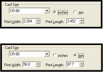
• CR-80 (default values): Card Size supported is 2.204 X 3.452 |
|
(56 X 87.7 mm). |
|
Standard Card Size in inches (HDP5000 Printer Driver > Card tab) |
|
Standard Card Size in mm (HDP5000 Printer Driver > Card tab) |
|
|
HDP5000 High Definition Card Printer/Encoder User Guide (Rev. 1.4) |
2-8 |

RESTRICTED USE ONLY Fargo Electronics, Inc.
Technical Specifications (continued)
Term |
Description |
|
|
|
|
Card Size |
Sets Custom Card Size when closing dialog box. |
|
(Custom |
• Print Width default = 2.440, upper limit = 2.440, lower limit = |
|
selection) |
||
1.000, cannot be null |
||
|
||
|
• Print Length default = 3.704, upper limit = 3.704, lower limit = |
|
|
3.000, cannot be null |
|
|
Changing back to CR-80 resets to CR-80 defaults. |
|
|
Custom Card Size in inches (HDP5000 Printer Driver > Card tab) |
|
|
Custom Card Size in mm (HDP5000 Printer Driver > Card tab) |
|
|
|
|
Card Size (inches |
Choice of inches or mm changes the counter choice on the K Panel |
|
and mm) |
Resin tab. See below. |
|
|
• Inches displays card size in inches. |
|
|
• mm displays card size in mm. |
|
|
Changing Print Width or Print Length dimensions automatically |
|
|
changes drop down to Custom. |
|
|
|
HDP5000 High Definition Card Printer/Encoder User Guide (Rev. 1.4) |
2-9 |
RESTRICTED USE ONLY Fargo Electronics, Inc.
Technical Specifications (continued)
Term |
Description |
||
|
|
||
Colors (dpi) |
300 dpi (11.8 dots/mm) |
||
|
|
|
|
Dimensions |
• |
HDP5000: 11.50"H x 12.25"W x 9.25"D / 292mmH x 313mmW x |
|
|
|
235mmD |
|
|
• |
HDP5000 + Dual-Sided Module: 11.50"H x 17.50"W x 9.25"D / |
|
|
|
292mmH x 445mmW x 235mmD |
|
|
• |
HDP5000 + Single-Sided Lam Module: 12.75"H x 25"W x |
|
|
|
9.25"D / 324mmH x 635mmW x 235mmD |
|
|
• HDP5000 + Dual-Sided Module + Dual-Sided Lam Module: |
||
|
|
12.75"H x 30"W x 9.25"D / 324mmH x 762mmW x 235mmD |
|
|
• |
Lam Module: 12.75"H x 12.25"W x 9.25"D / 324mmH x |
|
|
|
313mmW x 235mmD |
|
|
|
||
Display |
User-friendly, SmartScreen™ LCD Control Panel |
||
|
|
|
|
Encoding Options |
• |
ISO Magnetic Stripe Encoding Module, dual highand low- |
|
(only HDP5000 |
|
coercivity, Tracks 1, 2 and 3 |
|
and HDP5000- |
• JIS II Magnetic Stripe Encoding Module |
||
LC) |
|||
• E-card Docking Station (required for all e-card options or 3rd |
|||
|
|||
|
|
party smart card encoding) |
|
|
• Contact Smart Card Encoder (ISO 7816), Parts 1-4; T=0 and |
||
|
|
T=1 |
|
|
• Contactless Smart Card Encoder (Mifare®) |
||
|
• |
Prox Card Encoder (HID read-only) (Note: Corporate Express |
|
|
|
1000 Cards can be used with special order Weigand/ASCII |
|
|
|
Converter) |
|
|
• |
iCLASS™ |
|
|
|
|
|
HDP5000 High Definition Card Printer/Encoder User Guide (Rev. 1.4) |
2-10 |
RESTRICTED USE ONLY Fargo Electronics, Inc.
Technical Specifications (continued)
Term |
Description |
|
|
|
|
Fargo Certified |
Fargo Card Printer/Encoder requires highly specialized media to |
|
Supplies |
function properly. |
|
|
To maximize printed card quality and durability, Printhead life and |
|
|
Printer/Encoder reliability, use only Fargo Certified Supplies, Fargo |
|
|
warranties are void, where not prohibited by law, when non-Fargo |
|
|
Certified Supplies are used. |
|
|
|
|
HDP Film Options |
• |
Clear, 1,500 prints |
|
• Standard Holographic (500 prints) (only HDP5000 and |
|
|
|
HDP5000-LC) |
|
• Custom Holographic, special order (500 prints) (only HDP5000 |
|
|
|
and HDP5000-LC) |
|
|
|
HDP Film |
77ºF (25ºC) or lower for no longer than 1.5 years. |
|
Storage |
|
|
Temperature |
|
|
|
|
|
Humidity |
20% to 80% (non-condensing) |
|
|
|
|
Input Hopper |
HDP5000 and HDP5000-LC: |
|
Card Capacity |
• |
100 cards (.030/.762mm) |
|
||
|
|
|
Interface |
• USB 2.0 (high speed) and Ethernet with internal print server |
|
|
• Interfacing information for E-card Options |
|
|
|
|
Maximum |
2.125W / 54mmW |
|
Accepted Card |
|
|
Width |
|
|
|
|
|
Maximum |
3.375L / 85.6mmL |
|
Accepted Card |
|
|
Length |
|
|
|
|
|
HDP5000 High Definition Card Printer/Encoder User Guide (Rev. 1.4) |
2-11 |

RESTRICTED USE ONLY Fargo Electronics, Inc.
Technical Specifications (continued)
Term |
Description |
|
|
Memory |
16MB RAM |
|
|
Operating |
65º F to 90º F (18º C to 32º C). |
Temperature |
|
|
|
Options |
• Card Lamination Module – single-sided or double sided |
|
• Magnetic stripe encoding dual-sided (simultaneous) |
|
• 200-card input hopper |
|
• Smart card encoding (contact/contactless) |
|
• Dual-sided printing |
|
• Door and cartridge locks |
|
• Printer cleaning kit |
Output Hopper |
HDP5000/HDP5000-LC |
||
Card Capacity |
• |
200 cards (.030mm) |
|
|
|||
|
|
||
Overlaminate |
All overlaminates are available in either clear, holographic globe |
||
Options |
design or custom holographic design. They can also be optimized |
||
(HDP5000-LC |
for use with smart cards and Magnetic Stripes. |
||
and HDP5000 |
Here are the options: |
||
only) |
|||
• Thermal Transfer Overlaminate, .25 mil thick, 500 prints |
|||
|
|||
|
• PolyGuard® Overlaminate, 1.0 mil and .6 mil thick, 250 prints |
||
|
|
(PolyGuard available in a CR-80 patch size) |
|
|
|
|
|
Power Supply |
• |
80W for HDP5000 |
|
|
• 160W (two 80W bricks) for the HDP5000-LC |
||
|
(Note: This product is intended to be supplied by a Listed Power |
||
|
Unit marked "Class 2" and rated for 24 V dc, 3.75 to 5 A.) |
||
|
|
||
Print Area |
Over-the-edge on CR-80 cards. |
||
|
|
||
Printing Method |
HDP™ Dye-Sublimation / Resin Thermal Transfer |
||
HDP5000 High Definition Card Printer/Encoder User Guide (Rev. 1.4) |
2-12 |

RESTRICTED USE ONLY Fargo Electronics, Inc.
Technical Specifications (continued)
Term |
Description |
|
|
Print Ribbon |
HDP5000 and HDP5000-LC (prints or images): |
Options |
• Full color, YMC*, 750 prints |
|
|
|
• Full color with resin black, YMCK*, 500 prints |
|
• Full color with two resin black Panels, YMCKK*, 500 prints |
|
• Full color YMC with resin black and heat seal panel for difficult- |
|
to-print surfaces, YMCKH*, 500 prints |
|
• Full color YMC with resin black and UV fluorescing panel, |
|
YMCFK*, 500 prints |
|
*Indicates the Ribbon type and the number of Ribbon panels printed |
|
where Y=Yellow, M=Magenta, C=Cyan, K=Resin Black, H=Heat |
|
Seal and F=Fluorescing |
Print Speed- |
HDP5000 and HDP5000-LC (see note below): |
Batch Mode |
• 38 seconds per card / 95 cards per hour (YMC with transfer)* |
|
|
|
• 46 seconds per card / 78 cards per hour (YMCK with transfer)* |
|
• 70 seconds per card / 51 cards per hour (YMCKK with |
|
transfer)* |
|
• 70 seconds per card / 51 cards per hour (YMCFK with |
|
transfer)* |
|
• 50 seconds per card / 72 cards per hour (YMCK with transfer |
|
and dual-sided, simultaneous lamination)* |
|
• 75 seconds per card / 48 cards per hour (YMCKK with transfer |
|
and dual-sided, simultaneous lamination)* |
|
Print speed indicates an approximate print speed and is measured |
|
from the time a card feeds into the Printer to the time it ejects from |
|
the Printer. |
|
• Print speeds do not include encoding time or the time needed |
|
for the PC to process the image. |
|
• Process time is dependent on the size of the file, the CPU, |
|
amount of RAM and the amount of available resources at the |
|
time of the print. |
|
|
Resolution |
300 dpi (11.8 dots/mm) |
HDP5000 High Definition Card Printer/Encoder User Guide (Rev. 1.4) |
2-13 |
RESTRICTED USE ONLY Fargo Electronics, Inc.
Technical Specifications (continued)
Term |
Description |
|
|
|
|
Single Wire USB |
• ISO Magnetic Stripe Encoding, dual highand low-coercivity, |
|
2.0 Encoding |
|
Tracks 1, 2 and 3 |
Options |
• Contactless Smart Card Encoder (HID iClass and MIFARE) |
|
|
||
|
• Contact Smart Card Encoder reads from and writes to all |
|
|
|
ISO7816-1/2/3/4 memory and microprocessor smart cards (T=0, |
|
|
T=1) as well as synchronous cards |
|
• Prox Card Reader (HID read-only) |
|
|
|
|
Software Drivers |
Windows® 2000 / XP / Server 2003 |
|
|
|
|
Supply |
50 Hz / 60 Hz |
|
Frequency |
|
|
|
|
|
Supply Voltage |
100-240 VAC, 3.8A (HDP5000 and HDP5000-LC) |
|
|
|
|
Supported |
HDP5000: |
|
Printers/Models |
• |
Ethernet |
|
||
|
• |
USB |
|
HDP5000 with Card Lamination Module: |
|
|
• |
Ethernet |
|
• |
USB |
|
|
|
HDP5000 High Definition Card Printer/Encoder User Guide (Rev. 1.4) |
2-14 |
 Loading...